EP3876401A1 - Electronic control assembly and electric appliance - Google Patents
Electronic control assembly and electric appliance Download PDFInfo
- Publication number
- EP3876401A1 EP3876401A1 EP19911192.3A EP19911192A EP3876401A1 EP 3876401 A1 EP3876401 A1 EP 3876401A1 EP 19911192 A EP19911192 A EP 19911192A EP 3876401 A1 EP3876401 A1 EP 3876401A1
- Authority
- EP
- European Patent Office
- Prior art keywords
- electromagnetic compatibility
- filter circuit
- magnetic bead
- motor
- electrical control
- Prior art date
- Legal status (The legal status is an assumption and is not a legal conclusion. Google has not performed a legal analysis and makes no representation as to the accuracy of the status listed.)
- Granted
Links
- 238000001914 filtration Methods 0.000 claims abstract description 12
- 239000011324 bead Substances 0.000 claims description 123
- 239000003990 capacitor Substances 0.000 claims description 59
- 230000005670 electromagnetic radiation Effects 0.000 abstract description 6
- 238000010586 diagram Methods 0.000 description 9
- 230000020169 heat generation Effects 0.000 description 6
- 230000005540 biological transmission Effects 0.000 description 5
- 238000004519 manufacturing process Methods 0.000 description 5
- 230000002238 attenuated effect Effects 0.000 description 4
- 230000036039 immunity Effects 0.000 description 4
- 238000001228 spectrum Methods 0.000 description 4
- 230000001629 suppression Effects 0.000 description 4
- 238000004804 winding Methods 0.000 description 4
- 239000002184 metal Substances 0.000 description 3
- 238000005406 washing Methods 0.000 description 3
- 230000003247 decreasing effect Effects 0.000 description 2
- 230000000694 effects Effects 0.000 description 2
- 238000005516 engineering process Methods 0.000 description 2
- 238000009434 installation Methods 0.000 description 2
- 238000000034 method Methods 0.000 description 2
- 230000006641 stabilisation Effects 0.000 description 2
- 238000011105 stabilization Methods 0.000 description 2
- 229910000859 α-Fe Inorganic materials 0.000 description 2
- 230000033228 biological regulation Effects 0.000 description 1
- 238000006243 chemical reaction Methods 0.000 description 1
- 230000005611 electricity Effects 0.000 description 1
- 230000017525 heat dissipation Effects 0.000 description 1
- 230000001939 inductive effect Effects 0.000 description 1
- 238000002955 isolation Methods 0.000 description 1
- 230000035945 sensitivity Effects 0.000 description 1
- 229910000679 solder Inorganic materials 0.000 description 1
- 230000003068 static effect Effects 0.000 description 1
- 238000003466 welding Methods 0.000 description 1
Images


Classifications
-
- H—ELECTRICITY
- H02—GENERATION; CONVERSION OR DISTRIBUTION OF ELECTRIC POWER
- H02K—DYNAMO-ELECTRIC MACHINES
- H02K11/00—Structural association of dynamo-electric machines with electric components or with devices for shielding, monitoring or protection
- H02K11/02—Structural association of dynamo-electric machines with electric components or with devices for shielding, monitoring or protection for suppression of electromagnetic interference
-
- H—ELECTRICITY
- H05—ELECTRIC TECHNIQUES NOT OTHERWISE PROVIDED FOR
- H05K—PRINTED CIRCUITS; CASINGS OR CONSTRUCTIONAL DETAILS OF ELECTRIC APPARATUS; MANUFACTURE OF ASSEMBLAGES OF ELECTRICAL COMPONENTS
- H05K1/00—Printed circuits
- H05K1/02—Details
- H05K1/0213—Electrical arrangements not otherwise provided for
- H05K1/0216—Reduction of cross-talk, noise or electromagnetic interference
- H05K1/0218—Reduction of cross-talk, noise or electromagnetic interference by printed shielding conductors, ground planes or power plane
-
- H—ELECTRICITY
- H05—ELECTRIC TECHNIQUES NOT OTHERWISE PROVIDED FOR
- H05K—PRINTED CIRCUITS; CASINGS OR CONSTRUCTIONAL DETAILS OF ELECTRIC APPARATUS; MANUFACTURE OF ASSEMBLAGES OF ELECTRICAL COMPONENTS
- H05K1/00—Printed circuits
- H05K1/02—Details
- H05K1/0213—Electrical arrangements not otherwise provided for
- H05K1/0216—Reduction of cross-talk, noise or electromagnetic interference
- H05K1/023—Reduction of cross-talk, noise or electromagnetic interference using auxiliary mounted passive components or auxiliary substances
- H05K1/0233—Filters, inductors or a magnetic substance
Definitions
- the motor is prone to produce noise with an extremely wide spectrum while running, which is easily conducted to other circuit modules of the electrical device via a ground wire, increasing electromagnetic compatibility interference of the electrical device.
- the electrical control assembly may include an electrical control board, a power filter circuit and an electromagnetic compatibility filter circuit.
- the electrical control board may be provided with a system protection ground, a power input terminal and a ground terminal configured to access a power supply, and a power output terminal and a motor ground terminal configured to access a motor, wherein the ground terminal may be connected with the system protection ground.
- the electromagnetic compatibility filter circuit 20 may be connected in series between the ground wire of the housing of the motor M1 and the system protection ground GND
- One end of the electromagnetic compatibility filter circuit 20 may be electrically connected to the housing of the motor M1 via the motor ground terminal CN22 and may be also connected to the ground end of the power filter circuit 10, and the other end may be connected to the system protection ground GND
- the electromagnetic compatibility filter circuit 20 can provide high frequency impedance.
- the connection between the electromagnetic compatibility filter circuit 20 and the power filter circuit 10 may be equivalent to a parallel connection.
- the electromagnetic compatibility filter circuit 20 may include an inductor L2.
- a first end of the inductor L2 may be the input end of the electromagnetic compatibility filter circuit 20.
- the second end of the inductor L2 may be the output end of the power filter circuit 10.
Landscapes
- Physics & Mathematics (AREA)
- Electromagnetism (AREA)
- Engineering & Computer Science (AREA)
- Power Engineering (AREA)
- Microelectronics & Electronic Packaging (AREA)
- Inverter Devices (AREA)
Abstract
Description
- This application claims priority to
Chinese Patent Application No. 201910077807.8, filed on January 25, 2019 - The described embodiments relate to the field of electrical control technology, and in particular to an electrical control assembly and electrical device.
- Electromagnetic compatibility refers to an ability of a device or a system to operate in an electromagnetic environment in accordance with requirements and without producing intolerable electromagnetic interference to any device in the environment. Therefore, electromagnetic compatibility has two requirements: on the one hand, the electromagnetic interference generated by the device during a normal operation process to the environment where it is located cannot exceed a certain limitation; on the other hand, the device has a certain degree of immunity to the electromagnetic interference present in the environment where it is located, i.e. electromagnetic sensitivity.
- At present, for an electrical device with a motor, the motor is prone to produce noise with an extremely wide spectrum while running, which is easily conducted to other circuit modules of the electrical device via a ground wire, increasing electromagnetic compatibility interference of the electrical device.
- The present disclosure provides an electrical control assembly and electrical device for the purpose of suppressing electromagnetic compatibility electromagnetic radiation generated during the operation of a motor and improving the electromagnetic compatibility interference immunity of the electrical device.
- To achieve the above purpose, the present disclosure provides an electrical control assembly. The electrical control assembly may include an electrical control board, a power filter circuit and an electromagnetic compatibility filter circuit.
- The electrical control board may be provided with a system protection ground, a power input terminal and a ground terminal configured to access a power supply, and a power output terminal and a motor ground terminal configured to access a motor, wherein the ground terminal may be connected with the system protection ground.
- An input end of the power filter circuit may be connected with the power input terminal. An output end of the power filter circuit may be connected with the power output terminal.
- An input end of the electromagnetic compatibility filter circuit may be connected with the motor ground terminal and a ground end of the power filter circuit. An output end of the power filter circuit may be connected with the system reference ground.
- Optionally, the ground terminal may include a plurality of plug-in ends. The motor ground terminal may include a plurality of plug-in ends. A plurality of printed circuit board wires may be arranged on the electrical control board. First ends of the plurality of printed circuit board wires may be connected to the plurality of plug-in ends of the ground terminal in one-to-one correspondence. The other ends of the plurality of printed circuit board wires may be connected to the plurality of plug-in ends of the motor ground terminal in one-to-one correspondence.
- The electromagnetic compatibility filtering circuit may include a plurality of electromagnetic compatibility filter branches. Each of the plurality of electromagnetic compatibility filter branches may be connected in series to a corresponding printed circuit board wire.
- Optionally, the ground terminal may include two plug-in ends. The motor ground terminal may include two plug-in ends. A first printed circuit board wire and a second printed circuit board wire may be arranged on the electrical control board. The first printed circuit board wire may be connected with a first plug-in end of the motor ground terminal and a first plug-in end of the ground terminal. The second printed circuit board wire may be connected with a second plug-in end of the motor ground terminal and a second plug-in end of the ground terminal.
- The electromagnetic compatibility filter circuit may include two electromagnetic compatibility filter branches. One of the two electromagnetic compatibility filter branches may be connected in series to the first printed circuit board wire. The other of the two electromagnetic compatibility filter branches may be connected in series to the second printed circuit board wire.
- Optionally, the electromagnetic compatibility filter circuit may include a first magnetic bead. A first end of the first magnetic bead may be the input end of the electromagnetic compatibility filter circuit. A second end of the first magnetic bead may be the output end of the power filter circuit.
- Optionally, the quantity of the first magnetic bead may be multiple. A plurality of the first magnetic beads may be connected in series to the first printed circuit board wire and the second printed circuit board wire.
- Optionally, the electromagnetic compatibility filter circuit may include an inductor. A first end of the inductor may be the input end of the electromagnetic compatibility filter circuit. A second end of the inductor may be the output end of the power filter circuit.
- Optionally, the power filter circuit may include a common mode choke, a first Y-capacitor and a second Y-capacitor. Each of two input ends of the common mode choke may be connected to an input end of the power supply. Two output ends of the common mode choke may be connected to a first end of the first Y-capacitor and a first end of the second Y-capacitor respectively. A second end of the first Y-capacitor and a second end of the second Y-capacitor may be each connected to an input end of the electromagnetic compatibility filter circuit.
- Optionally, the electromagnetic compatibility filter circuit may further include a second magnetic bead. A first end of the second magnetic bead may be connected to the motor ground terminal. A second end of the second magnetic bead may be connected to the first end of the first magnetic bead.
- Optionally, the electromagnetic compatibility filter circuit may further include a third magnetic bead. A first end of the third magnetic bead may be interconnected with the first magnetic bead and the second end of the first Y-capacitor. A second end of the third magnetic bead may be interconnected with a second end of the second magnetic bead and the motor ground terminal.
- Optionally, the electromagnetic compatibility filter circuit may further include a fourth magnetic bead. The fourth magnetic bead may be connected in series between the first Y-capacitor and the first magnetic bead.
- Alternatively, the fourth magnetic bead may be connected in series between the second Y-capacitor and the first magnetic bead.
- Alternatively, the fourth magnetic bead may be connected in series between an output end of the common mode choke and the first Y-capacitor.
- Alternatively, the fourth magnetic bead may be connected in series between an output end of the common mode choke and the second Y-capacitor.
- Optionally, the electromagnetic compatibility filter circuit may include an inductor. A first end of the inductor may be the input end of the electromagnetic compatibility filter circuit. A second end of the inductor may be the output end of the power filter circuit.
- The present disclosure further provides an electrical device. The electrical device may include a motor and the electrical control assembly as described above. A power output terminal of the electrical control assembly may be connected with the motor. The electrical control assembly may include an electrical control board, a power filter circuit and an electromagnetic compatibility filter circuit. The electrical control board may be provided with a system protection ground, a power input terminal and a ground terminal configured to access a power supply, and a power output terminal and a motor ground terminal configured to access a motor. The ground terminal may be connected with the system protection ground. An input end of the power filter circuit may be connected with the power input terminal. An output end of the power filter circuit may be connected with the power output terminal. An input end of the electromagnetic compatibility filter circuit may be connected with the motor ground terminal and a ground end of the power filter circuit. An output end of the power filter circuit may be connected with the system reference ground.
- In the present disclosure, the electromagnetic compatibility filter circuit may be connected in series between the ground wire of the housing of the motor and the system protection ground. One end of the electromagnetic compatibility filter circuit may be electrically connected to the housing of the motor via the motor ground terminal and may be also connected to the ground end of the power filter circuit, and the other end may be connected to the system protection ground. When the noise generated during the operation of the motor with an extremely wide frequency spectrum flows to the electrical control board through the ground wire and the motor ground terminal, the electromagnetic compatibility filter circuit can provide high frequency impedance. In this case, the connection between the electromagnetic compatibility filter circuit and the power filter circuit may be equivalent to a parallel connection. Since the electromagnetic compatibility filter circuit is equivalent to a high frequency impedance circuit, the current flowing through the electromagnetic compatibility filter circuit may be much smaller than that flowing through the power filter circuit. In this way, a current loop may be formed among the housing of the motor, the ground wire of the motor, the motor ground terminal, the ground end of the power filter circuit, the output end of the power filter circuit, the power output terminal, a power end of the motor and windings of the motor. The electromagnetic compatibility interference signal can return to the generation source of the electromagnetic compatibility interference signal through the housing of the motor, the ground wire, the ground terminal of the motor, the power filter circuit and the power output terminal, thereby preventing the electromagnetic compatibility interference signal from flowing out of the motor. Moreover, the electromagnetic compatibility interference signal may also be gradually consumed in a form of heat generation during flowing through the current loop formed by the power filter circuit, the windings of the motor and the housing of the motor and other structures, thus preventing the electromagnetic compatibility interference of the motor from exceeding a standard. In the present disclosure, the electromagnetic compatibility filter circuit may be arranged between the ground wire of the motor and the system protection ground to increase the high-frequency impedance of the current loop on the path where the common mode interference generated by the motor flows back to the line impedance stabilization network of the electrical control board through the system protection ground, so that the power filter circuit, which is set in parallel with the electromagnetic compatibility filter circuit, can share a larger common mode current and the electromagnetic compatibility interference signal can be attenuated by the power filter circuit, thereby suppressing the transmission of electromagnetic compatibility interference signals and the like to the system protection ground. In this way, the electromagnetic compatibility electromagnetic radiation generated by the motor can be suppressed and the electromagnetic compatibility interference immunity of electrical device can be improved.
-
-
FIG. 1 is a schematic diagram of functional modules of an electrical control assembly according to an embodiment of the present disclosure; -
FIG. 2 is a schematic diagram of functional modules of an electrical control assembly according to another embodiment of the present disclosure; -
FIG. 3 is a schematic circuit diagram of an electrical control assembly according to a first embodiment of the present disclosure; -
FIG. 4 is a schematic circuit diagram of an electrical control assembly according to a second embodiment of the present disclosure; -
FIG. 5 is a schematic circuit diagram of an electrical control assembly according to a third embodiment of the present disclosure; -
FIG. 6 is a structural view of an electrical control assembly according to an embodiment of the present disclosure; -
FIG. 7 is a schematic circuit diagram of an electrical control assembly according to a fourth embodiment of the present disclosure; -
FIG. 8 is a schematic circuit diagram of an electrical control assembly according to a fifth embodiment of the present disclosure; -
FIG. 9 is a schematic circuit diagram of an electrical control assembly according to a sixth embodiment of the present disclosure; -
FIG. 10 is a schematic circuit diagram of an electrical control assembly according to a sixth embodiment of the present disclosure. - Reference numerals in the drawings are described as follows.
[Form 1] reference numeral name reference numeral name 100 electrical control board CN11 power input terminal GND system protection ground CN12 ground terminal 10 power filter circuit CN21 power output terminal 20 electromagnetic compatibility filter circuit CN22 motor ground terminal 30 rectifier circuit FB1 first magnetic bead 40 PFC circuit FB2 second magnetic bead 50 IPM FB3 third magnetic bead L1 common mode choke FB4 fourth magnetic bead L2 inductor C1 first Y capacitor M1 motor C2 second Y capacitor - The present disclosure provides an electrical control assembly for an electrical device. The electrical device may be an air conditioner, a washing machine or other household electrical device. The electric control assembly may be particularly suitable for air conditioners.
- Referring to
FIGS. 1 and 2 , in an embodiment of the present disclosure, the electrical control assembly may include anelectrical control board 100, apower filter circuit 10 and an electromagnetic compatibility (EMC)filter circuit 20. - The
electrical control board 100 may be provided with a system protection ground GND, a power input terminal CN11 and a ground terminal CN12 configured to access a power supply, and a power output terminal CN21 and a motor ground terminal CN22 configured to access a motor M1. The ground terminal CN12 may be connected to the system protection ground GND - An input end of the
power filter circuit 10 may be connected with the power input terminal. An output end of thepower filter circuit 10 may be connected with the power output terminal CN21. - An input end of the electromagnetic
compatibility filter circuit 20 may be connected with the motor ground terminal CN22 and a ground end of thepower filter circuit 10, respectively. An output end of thepower filter circuit 10 may be connected with the system reference ground. - In this embodiment, the
electrical control board 100 may be a single-sided board or a double-sided board, which can be determined according to installation space and installation location of the electrical device in the actual application. In some embodiments, the electrical control assembly may further include arectifier circuit 30, a PFC (power factor correction)circuit 40 and an IPM (intelligent power module) 50. The power input terminal CN11 may include a zero wire AC-N and a fire wire AC-L. The power output terminal CN21 may include a UVW three-phase output port. -
Rectifier circuit 30 may be a rectifier bridge stack, or arectifier circuit 30 consisting of four separate diodes.Rectifier circuit 30 may convert an incoming alternating current (AC) power to direct current (DC) power and then output the DC power to thePFC circuit 40 for a power factor adjustment. ThePFC circuit 40 may be apassive PFC circuit 40 to form a step-upPFC circuit 40, or a step-downPFC circuit 40, or a step-up and step-downPFC circuit 40. ThePFC circuit 40 may perform a power factor adjustment on the incoming DC, for example by increasing a voltage of the DC power to be stabilized at 380V so that an input current follows an input voltage, maintaining the power factor of the DC power above 0.9. After being adjusted, the DC power can be output to a rear stage circuit, such as theIPM 50. The DC power after being adjusted can also pass through a switching power circuit (not shown) to generate driving voltages with various values, e.g. 5V, 15V, etc. to power other components on the circuit board such as a main controller. TheIPM 50 can be arranged on theelectrical control board 100 and integrate a driving circuit and a plurality of power switching tubes. The plurality of power switching tubes can form a driving inverter circuit. For example, six power switching tubes can form a three-phase inverter bridge circuit, or four power switching tubes can form a two-phase inverter bridge circuit. Each power switching tube may be a MOS tube or an IGBT. TheIPM 50 can be configured to drive the motor M1 of a compressor. Of course, in other embodiments,IPM 50 can also be configured to drive frequency converters and various inverter power supplies of other motors M1, and can be applied in areas such as frequency conversion and speed regulation, metallurgical machinery, electric traction, servo drive, and inverter appliance such as air conditioner and so on. - In the present embodiment, the output end of the
power filter circuit 10 may be connected to an input end of therectifier circuit 30. The input end of thepower filter circuit 10 may be connected to the power input terminal CN11. After the power input terminal CN11 accesses an AC power supply, common mode current in this input power supply can be suppressed by thepower filter circuit 10, thereby suppressing grid noise and high harmonics of the AC power supply, and the noise and high frequency harmonics generated by a switching power supply, meanwhile preventing the electromagnetic interference generated in a power circuit from radiating to other circuit modules. - It should be noted that the motor M1 may be a motor M1 of a compressor, a motor M1 of a fan, or other motor M1 in the electrical device. A housing of the motor M1 may generally be a metal housing. A ground wire of the motor M1 can generally be connected to the metal housing and further connected to a ground wire on the
electrical control board 100 through a wire, so that the housing of the motor may also act as a ground protection wire, thus connecting all circuit modules on theelectrical control board 100 and the AC power supply together to form an equal potential, and forming a metal network loop, i.e. the system protection ground, to achieve a leakage protection and also to prevent static electricity from damaging the electrical device. The motor of the electrical device can be either a brushed motor or a brushless motor. When in operation, the motor may be prone to generate electromagnetic interference. For example, when a brushed motor M1 is used, due to an increase of DC resistance between the brush and commutator of the brushed motor, spark discharge may be prone to form, and the brushed motor M1 may be prone to generate noise with an extremely wide spectrum (continuously distributed from the mid-wave to the VHF band), while the brushed motor M1 is rotating. The brushless motor may also generate a high-frequency noise during an operation. The noise can be easily radiated to the housing of the motor M1 and conducted through the housing of the motor M1 and the ground wire to theelectrical control board 100 and then through theelectrical control board 100 to other circuit modules, which may even increase electromagnetic interference, i.e., electromagnetic compatibility interference signals among various electrical devices such as air conditioners and washing machines. - To solve the above problem, in this embodiment, the electromagnetic
compatibility filter circuit 20 may be connected in series between the ground wire of the housing of the motor M1 and the system protection ground GND One end of the electromagneticcompatibility filter circuit 20 may be electrically connected to the housing of the motor M1 via the motor ground terminal CN22 and may be also connected to the ground end of thepower filter circuit 10, and the other end may be connected to the system protection ground GND When the noise generated during the operation of the motor M1 with an extremely wide frequency spectrum flows to theelectrical control board 100 through the ground wire and the motor ground terminal CN22, the electromagneticcompatibility filter circuit 20 can provide high frequency impedance. In this case, the connection between the electromagneticcompatibility filter circuit 20 and thepower filter circuit 10 may be equivalent to a parallel connection. Since the electromagneticcompatibility filter circuit 20 is equivalent to a high frequency impedance circuit, the current flowing through the electromagneticcompatibility filter circuit 20 may be much smaller than that flowing through thepower filter circuit 10. In this way, a current loop may be formed among the housing of the motor M1, the ground wire of the motor M1, the motor ground terminal CN22, the ground end of thepower filter circuit 10, the output end of thepower filter circuit 10, the power output terminal, a power end of the motor M1 and windings of the motor M1. The electromagnetic compatibility interference signal can return to the generation source of the electromagnetic compatibility interference signal through the housing of the motor M1, the ground wire, the ground terminal of the motor M1, thepower filter circuit 10 and the power output terminal CN21, thereby preventing the electromagnetic compatibility interference signal from flowing out of the motor M1. Moreover, the electromagnetic compatibility interference signal may also be gradually consumed in a form of heat generation while flowing through the current loop formed by thepower filter circuit 10, the windings of the motor M1 and the housing of the motor M1 and other structures, thus preventing the electromagnetic compatibility interference of the motor M1 to theelectrical control board 100 and other modules in the electrical device from exceeding a standard. In the present disclosure, the electromagneticcompatibility filter circuit 20 may be arranged between the ground wire of the motor M1 and the system protection ground GND to increase the high-frequency impedance of the current loop on the path where the common mode interference generated by the motor M1 flows back to the line impedance stabilization network of theelectrical control board 100 through the system protection ground GND, so that thepower filter circuit 10, which is set in parallel with the electromagneticcompatibility filter circuit 20, can share a larger common mode current and the electromagnetic compatibility interference signal can be attenuated by thepower filter circuit 10, thereby suppressing the transmission of electromagnetic compatibility interference signals and the like to the system protection ground GND In this way, the electromagnetic compatibility electromagnetic radiation generated by the motor M1 can be suppressed and the electromagnetic compatibility interference immunity of electrical device can be improved. - As shown in
FIGS. 4 to 6 , both the ground terminal CN12 and the motor ground terminal CN22 may include a plurality of plug-in ends. A plurality of printed circuit board wires may also be provided on the electrical control board. First ends of the plurality of printed circuit board wires may be connected to the plurality of plug-in ends of the ground terminal CN12 in one-to-one correspondence. The other ends of the plurality of printed circuit board wires may be connected to the plurality of plug-in ends of the motor ground terminal CN22 in one-to-one correspondence. - The electromagnetic
compatibility filtering circuit 20 may include a plurality of electromagnetic compatibility filter branches. Each of the plurality of electromagnetic compatibility filter branches may be connected in series to a corresponding printed circuit board wire. - It should be noted that, currently, the ground wire of the motor is usually directly connected to the reference ground GND of the
electrical control board 100 through the motor ground terminal CN22, without setting up a printed circuit board wire. However, in the present embodiment, in order to suppress the electromagnetic compatibility electromagnetic radiation generated by the motor M1 and improve the electromagnetic compatibility anti-interference performance of the electrical device, the electromagneticcompatibility filter circuit 20 can be arranged between the ground wire of the motor M1 and the system protection ground GND - When the electromagnetic
compatibility filter circuit 20 is provided between the ground wire of the motor M1 and the system protection ground GND, it is necessary to provide printed circuit board wires for the ground wire of the motor M1 on theelectrical control board 100. However, according to the national standard, normally printed circuit board wires cannot be arranged between the ground wire of the motor M1 and the system protection ground GND, which cannot be used to provide ground continuity in order to avoid the problem of unmet ground continuity. For this reason, in the present disclosure, multiple printed circuit board wires can be provided to keep a low resistance of the ground wire, and both the ground terminal CN12 and the motor ground terminal CN2 have multiple plug-in ends, so that the electromagneticcompatibility filter circuit 20 can be configured to include multiple electromagnetic compatibility filter branches. In addition, the multiple electromagnetic compatibility filter branches may be connected in series with the printed circuit board wires, which can increase the high frequency impedance of the printed circuit board wires and thus increase the high frequency impedance of the loop, so that thepower filter circuit 10, which is arranged in parallel with the electromagneticcompatibility filter circuit 20, can share a larger common mode current. In this way, the restrictive requirements of the ground continuity of the printed circuit board can be satisfied, meanwhile the electromagnetic compatibility electromagnetic radiation generated by the motor M1 can be suppressed, thus improving the electromagnetic compatibility anti-interference performance of electrical device. - Further, both the ground terminal CN12 and the motor ground terminal CN22 may include two plug-in ends. A first printed circuit board wire and a second printed circuit board wire may also be provided on the
electrical control board 100. The first printed circuit board wire may be connected with a first plug-in end of the motor ground terminal CN22 and a first plug-in end of the ground terminal CN12. The second printed circuit board wire may be connected with a second plug-in end of the motor ground terminal CN22 and a second plug-in end of the ground terminal CN12. - The electromagnetic
compatibility filter circuit 20 may include two electromagnetic compatibility filter branches. One of the two electromagnetic compatibility filter branches may be connected in series to the first printed circuit board wire. The other of the two electromagnetic compatibility filter branches may be connected in series to the second printed circuit board wire. - It can be understood that in practical application, the ground terminal CN12 and the motor ground terminal CN22 on the
electric control board 100 may usually be provided as two, so that the AC power supply and the ground wire of the motor M1 can be connected to theelectrical control board 100. In this disclosure, two printed circuit board wires may be provided according to the number of ground terminal CN12 and motor ground terminal CN22, and the two ends of the printed circuit board wires may be connected to pads of the plug-in ends of the ground terminal CN12 and motor ground terminal CN22, respectively, and two electromagnetic compatibility filter branches can be connected in series to the printed circuit board wires. In this way, the restriction requirement to the continuity of the ground wire of the printed circuit board can be satisfied, meanwhile, process steps for manufacturing the electrical control assembly can be reduced and production cost of the electrical control assembly can be decreased. - Referring to
FIG. 3 , in one embodiment, the electromagneticcompatibility filter circuit 20 may include a first magnetic bead FB1. A first end of the first magnetic bead FB1 may be the input end of the electromagneticcompatibility filter circuit 20. A second end of the first magnetic bead FB1 may be the output end of thepower filter circuit 10. - In this embodiment, the first magnetic bead FB1 may be a ferrite bead. In some embodiments, the electromagnetic
compatibility filter circuit 20 may also be a ferrite magnetic ring. High frequency noise as well as some spike interference output from the housing of the motor M1 can be suppressed by means of the first magnetic bead FB1. The first magnetic bead FB1 may be connected in series between the housing of the motor M1 and the system protection ground GND to provide high frequency impedance for the circuit where the housing of the motor M1 and the system protection ground GND are located, so as to ensure that the common mode current flowing through the first magnetic bead FB1 is much smaller than the common mode current flowing through thepower filter circuit 10, so that most of the common mode current generated by the motor M1 can return to the interference source through thepower filter circuit 10 which is arranged in parallel with the first magnetic bead FBI, and the electromagnetic compatibility interference signal can be attenuated by the powersupply filter circuit 10, thereby suppressing the transmission of electromagnetic compatibility interference signal, etc. to the system protection ground GND - It is understandable that a through-core inductor may usually be connected in series to a power wire of the motor to suppress the electromagnetic compatibility of the electrical control assembly, which has higher costs. Moreover, since the through-core inductor has a large size, arranging the through-core inductor on the
electrical control board 100 will result in a complex configuration of theelectrical control board 100. In addition, since the heat generated by the through-core inductor is serious, a radiator will be needed for heat dissipation, which brings great inconvenience to the manufacturing of electrical control assembly. However, in the embodiment of the present disclosure, two printed circuit board wires may be arranged between the two plug-in ends of the ground terminal CN12 and the two plug-in ends of the motor ground terminal CN22, and the first magnetic bead FB1 may further be connected in series to the two printed circuit board wires with independent solder joints. Because of a small size of the first magnetic bead FB1, a simple circuit configuration and a lack of need for a heat sink, the difficulty of wiring the circuit of theelectrical control board 100 can be thus reduced, making the electrical control assembly easy to be implemented. In the present disclosure, instead of the through-core inductor, the magnetic bead FB1 may be used to reduce the use of heat sinks and the production costs of the electrical control assembly can be decreased. - Referring to
FIG. 6 , in one embodiment, both the ground terminal CN12 and the motor ground terminal CN22 may include a plurality of plug-in ends. - The quantity of the first magnetic bead FB1 may be multiple. First ends of a plurality of first magnetic beads FB1 may be connected to the plurality of plug-in ends of the motor ground terminal CN22 in one-to-one correspondence. Second ends of the plurality of first magnetic beads FB1 may be connected to the plurality of plug-in ends of the ground terminal CN22 in one-to-one correspondence.
- In this embodiment, the quantity of the first magnetic bead FB1 may be one or multiple, which can be determined according to the frequency of the electromagnetic interference generated by the motor M1. In practical application, the electromagnetic interference generated between a brush and a commutator of the motor M1 and by other components of the motor M1 may be detected, and the quantity of magnetic bead can be determined according to the frequency of the electromagnetic interference, in order to better suppress the transmission of the electromagnetic compatibility interference signal and the like to the system protection ground GND
- The quantity of first magnetic bead FB1 may be two. Correspondingly, plug-in pins of the motor ground terminal CN22 may be two and pins of the ground terminal CN12 may also be two. Among the two first magnetic beads FB1 in a parallel connection, two ends of one first magnetic bead FB1 may be respectively connected to one plug-in end of the motor ground terminal CN22 and one plug-in end of the ground terminal CN12, two ends of the other first magnetic bead FB1 may be connected to the other plug-in end of the motor ground terminal CN22 and the other plug-in end of the ground terminal CN12, respectively. In this way, while manufacturing the printed circuit board, two printed circuit board wires can be laid between the input end of the electromagnetic
compatibility filter circuit 20, i.e. the motor ground terminal CN22, and the output end of the electromagneticcompatibility filter circuit 20, i.e. the ground terminal CN12, as ground connections, and the first magnetic beads FB1 can be installed on both ground wires in order to play a role in isolation and filtering. - Referring to
FIG 4 , in some embodiments, the quantity of first magnetic bead FB1 may be multiple. A plurality of first magnetic beads FB1 may be connected in series to the first printed circuit board wire and the second printed circuit board wire, respectively. When the quantity of the first magnetic bead FB1 is a multiple, multiple first magnetic beads FB1 may be provided in series or in parallel, depending on the frequency of electromagnetic interference generated by the motor M1, without limitation here. - As shown in
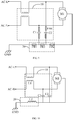
FIG. 7 , in one embodiment, thepower filter circuit 10 may include a common mode choke L1, a first Y-capacitor C1 and a second Y-capacitor C2. Each of two input ends of the common mode choke L1 may be connected to an input end of the power supply. Two output ends of the common mode choke L1 may be connected to a first end of the first Y-capacitor C1 and a first end of the second Y-capacitor C2, respectively. A second end of the first Y-capacitor C1 and a second end of the second Y-capacitor C2 may be each connected to an input end of the electromagneticcompatibility filter circuit 20, respectively. - In the present embodiment, when there is a differential mode interference signal in the AC power supply connected to the power access terminal, the magnetic fields generated by currents in two coils may cancel out due to the opposite direction of the magnetic fields as the differential mode current flows through the two coils of the common mode coil. When there is a common mode interference signal, since the common mode currents in the common mode choke L1 have a same direction, the two coils can generate magnetic fields in a same direction, thus increasing inductance of the two coils, i.e., increasing the inductive resistance of the two coils to the common mode current. In this way, the common mode current can be more suppressed, the purpose of attenuating the common mode currents can be achieved, thereby suppressing the common mode interference noise. The first Y capacitor C1 and the second Y capacitor C2 can play a filtering role on the common mode interference noise, so that the common mode interference can be significantly suppressed. The first Y-capacitor C1 and the second Y-capacitor C2 may be Y-capacitors whose specification parameters correspond to the frequency of electromagnetic compatibility interference, so that the electromagnetic compatibility interference signal can pass through the Y-capacitors more easily. The first Y-capacitor C1 and the second Y-capacitor C2 may be provided so that the electromagnetic compatibility interference signal flowing through can return to the motor M1 and can also be gradually consumed in the form of heat generation, thereby preventing the electromagnetic compatibility interference of the motor M1 from exceeding the standard.
- As shown in
FIG. 7 , in one embodiment, the electromagneticcompatibility filter circuit 20 may further include a second magnetic bead FB2. A first end of the second magnetic bead FB2 may be connected to the motor ground terminal CN22. A second end of the second magnetic bead FB2 may be connected to the first end of the first magnetic bead FB1. - In this embodiment, the second magnetic bead FB2 may be connected between the first magnetic bead FB1 and the motor ground terminal CN22. In other words, one end of the second magnetic bead FB2 may be connected to the motor ground terminal CN22. The other end of the second magnetic bead FB2 may be connected to a ground terminal of the first magnetic bead FBI, the first Y capacitor C1 and the second Y capacitor C2. The second magnetic bead FB2 can be configured to increase impedance between the housing of the motor M1 and the system protection ground GND Impedance values of the first magnetic bead FB1 and the second magnetic bead FB2 can be the same or different. The common mode current generated by the motor M1 can be firstly suppressed by the second magnetic bead FB2 and consumed in the form of heat generation, and then shunted by the first magnetic bead FB1 and the
power filter circuit 10. Most of the common mode current can return to the interference source via thepower filter circuit 10, and the electromagnetic compatibility interference signal can be attenuated by thepower filter circuit 10, thereby suppressing the transmission of the electromagnetic compatibility interference signal, etc. to the system protection ground GND - Referring to
FIG. 7 , in one embodiment, the electromagneticcompatibility filter circuit 20 may further include a third magnetic bead FB3. A first end of the third magnetic bead FB3 may be interconnected with the first magnetic bead FB1 and the second end of the first Y-capacitor C1. A second end of the third magnetic bead FB3 may be interconnected with a second end of the second magnetic bead FB2 and the motor ground terminal. - In this embodiment, the first magnetic bead FB1, the second magnetic bead FB2 and the third magnetic bead FB3 can be provided simultaneously, or only two of the first magnetic bead FBI, the second magnetic bead FB2 and the third magnetic bead FB3 can be provided. In other embodiments, of course, only one of the first magnetic bead FBI, the second magnetic bead FB2 and the third magnetic bead FB3 can be provided, without limitation here. In this embodiment, the first magnetic bead FBI, the second magnetic bead FB2 and the third magnetic bead FB3 are provided simultaneously. The first magnetic bead FB1 may be connected in parallel with the first Y-capacitor C1. The third magnetic bead FB3 may be connected in parallel with the second Y-capacitor C2 and then connected in series with the second magnetic bead FB2. The magnetic beads located in three positions can form different current loops for the common mode interference signal with the first Y capacitor C1 and the second Y capacitor C2 respectively, thus increasing speed of the common mode interference signal back to the interference source. Furthermore, the magnetic beads in each of the three positions can consume the electromagnetic interference signal in the form of heat generation, thereby improving the efficiency of the suppression of the electromagnetic interference signal.
- Referring to
FIGS. 7 to 9 , in one embodiment, the electromagneticcompatibility filter circuit 20 may further include a fourth magnetic bead FB4. The fourth magnetic bead FB4 may be connected in series between the first Y-capacitor C1 and the first magnetic bead FB1. - Alternatively, the fourth magnetic bead FB4 may be connected in series between the second Y-capacitor C2 and the first magnetic bead FB1.
- Alternatively, the fourth magnetic bead FB4 may be connected in series between an output end of the common mode choke L1 and the first Y-capacitor C1.
- Alternatively, the fourth magnetic bead FB4 may be connected in series between the output end of the common mode choke L1 and the second Y-capacitor C2.
- In this embodiment, the quantity of the fourth magnetic bead FB4 may be one. When the quantity of the fourth magnetic bead FB4 is one, the fourth magnetic bead FB4 may be arranged at either end of the first Y capacitor C1 or at either end of the second Y capacitor C2. Providing the fourth magnetic bead FB4 at the above position can improve the electromagnetic suppression effect of the
power filter circuit 10. In other embodiments, of course, the quantity of the fourth magnetic bead FB4 may also be multiple. A plurality of fourth magnetic beads FB4 can be arranged at both ends of the first Y-capacitor C1 and both ends of the second Y-capacitor C2, thus improving the effect of electromagnetic suppression of the powersupply filter circuit 10. Moreover, the plurality of fourth magnetic beads FB4 can consume the electromagnetic interference signal in the form of heat generation, thereby improving the efficiency of suppression of the electromagnetic interference signal. - Referring to
FIG. 10 , in one embodiment, the electromagneticcompatibility filter circuit 20 may include an inductor L2. A first end of the inductor L2 may be the input end of the electromagneticcompatibility filter circuit 20. The second end of the inductor L2 may be the output end of thepower filter circuit 10. - In this embodiment, the electromagnetic
compatibility filter circuit 20 can be implemented by means of the inductor L2, or a combination of magnetic beads and the inductor L2. The inductor L2 may be configured to increase the high frequency impedance between the housing of the motor M1 and the system protection ground GND, so that the common mode current can return to the interference source of the motor M1 via thepower filter circuit 10. - The present disclosure also provides an electrical device. The electrical device may include a motor M1 and an electrical control assembly as described above. A power output terminal of the electric control assembly may be connected to the motor. Detailed configuration of the electrical control assembly can be referred to the above-mentioned embodiments and will not be repeated here. It can be understood that, since the above-mentioned electrical control assembly is adopted in the electrical device of the present disclosure, the electrical device may include all the technical solutions in all the above-mentioned embodiments of the electrical control assembly and can achieve exactly the same technical effect, which will not be repeated here.
- In this embodiment, the electrical device can be an air conditioner, washing machine, refrigerator or other electrical device equipped with a motor. Alternatively, the electrical device may be an air conditioner including an indoor unit and an outdoor unit. The electric control assembly may be installed in the outdoor unit of the air conditioner. A mounting section for mounting the electrical control assembly may be arranged in the housing of the outdoor unit. The electrical control assembly may be arranged in the mounting section of the outdoor unit by one or a combination of screwing, bolting, riveting, welding, clamping and plugging.
- The above are only preferred embodiments of the present disclosure and are not intended to limit the scope of the present disclosure. Any equivalent structural changes made under the concept of the present disclosure, using the contents of the specification of the present disclosure and the accompanying drawings, or applied directly/indirectly in other related fields of technology are included in the scope of protection of the present disclosure.
Claims (16)
- An electrical control assembly, characterized by comprising:an electrical control board, provided with a system protection ground, a power input terminal and a ground terminal configured to access a power supply, and a power output terminal and a motor ground terminal configured to access a motor, wherein the ground terminal is connected with the system protection ground;a power filter circuit, wherein an input end of the power filter circuit is connected with the power input terminal, and an output end of the power filter circuit is connected with the power output terminal;an electromagnetic compatibility filter circuit, wherein an input end of the electromagnetic compatibility filter circuit is connected with the motor ground terminal and a ground end of the power filter circuit, and an output end of the power filter circuit is connected with the system reference ground.
- The electrical control assembly as claimed in claim 1, wherein: the ground terminal comprises a plurality of plug-in ends, the motor ground terminal comprises a plurality of plug-in ends, a plurality of printed circuit board wires are arranged on the electrical control board, first ends of the plurality of printed circuit board wires are connected to the plurality of plug-in ends of the ground terminal in one-to-one correspondence, the other ends of the plurality of printed circuit board wires are connected to the plurality of plug-in ends of the motor ground terminal in one-to-one correspondence;
the electromagnetic compatibility filtering circuit comprises a plurality of electromagnetic compatibility filter branches, each of the plurality of electromagnetic compatibility filter branches is connected in series to a corresponding printed circuit board wire. - The electrical control assembly as claimed in claim 2, wherein the ground terminal comprises two plug-in ends, the motor ground terminal comprises two plug-in ends, a first printed circuit board wire and a second printed circuit board wire are arranged on the electrical control board, the first printed circuit board wire is connected with a first plug-in end of the motor ground terminal and a first plug-in end of the ground terminal, the second printed circuit board wire is connected with a second plug-in end of the motor ground terminal and a second plug-in end of the ground terminal;
the electromagnetic compatibility filter circuit comprises two electromagnetic compatibility filter branches, one of the two electromagnetic compatibility filter branches is connected in series to the first printed circuit board wire, the other of the two electromagnetic compatibility filter branches is connected in series to the second printed circuit board wire. - The electrical control assembly as claimed in claim 3, wherein the electromagnetic compatibility filter circuit comprises a first magnetic bead, a first end of the first magnetic bead is the input end of the electromagnetic compatibility filter circuit, a second end of the first magnetic bead is the output end of the power filter circuit.
- The electrical control assembly as claimed in claim 3, wherein the quantity of the first magnetic bead is multiple, a plurality of the first magnetic beads are connected in series to the first printed circuit board wire and the second printed circuit board wire.
- The electrical control assembly as claimed in claim 3, wherein the electromagnetic compatibility filter circuit comprises an inductor, a first end of the inductor is the input end of the electromagnetic compatibility filter circuit, a second end of the inductor is the output end of the power filter circuit.
- The electrical control assembly as claimed in claim 4, wherein the power filter circuit comprises a common mode choke, a first Y-capacitor and a second Y-capacitor, each of two input ends of the common mode choke is connected to an input end of the power supply, two output ends of the common mode choke are connected to a first end of the first Y-capacitor and a first end of the second Y-capacitor respectively, a second end of the first Y-capacitor and a second end of the second Y-capacitor are each connected to an input end of the electromagnetic compatibility filter circuit.
- The electrical control assembly as claimed in claim 7, wherein the electromagnetic compatibility filter circuit further comprises a second magnetic bead, a first end of the second magnetic bead is connected to the motor ground terminal, a second end of the second magnetic bead is connected to the first end of the first magnetic bead.
- The electrical control assembly as claimed in claim 7, wherein the electromagnetic compatibility filter circuit further comprises a third magnetic bead, a first end of the third magnetic bead is interconnected with the first magnetic bead and the second end of the first Y-capacitor, a second end of the third magnetic bead is interconnected with a second end of the second magnetic bead and the motor ground terminal.
- The electrical control assembly as claimed in claim 7, wherein the electromagnetic compatibility filter circuit further comprises a fourth magnetic bead, the fourth magnetic bead is connected in series between the first Y-capacitor and the first magnetic bead.
- The electrical control assembly as claimed in claim 7, wherein the fourth magnetic bead is connected in series between the second Y-capacitor and the first magnetic bead.
- The electrical control assembly as claimed in claim 7, wherein the fourth magnetic bead is connected in series between an output end of the common mode choke and the first Y-capacitor.
- The electrical control assembly as claimed in claim 7, wherein the fourth magnetic bead is connected in series between an output end of the common mode choke and the second Y-capacitor.
- The electrical control assembly as claimed in claim 5, wherein the power filter circuit comprises a common mode choke, a first Y-capacitor and a second Y-capacitor, each of two input ends of the common mode choke is connected to an input end of the power supply, two output ends of the common mode choke are connected to a first end of the first Y-capacitor and a first end of the second Y-capacitor respectively, a second end of the first Y-capacitor and a second end of the second Y-capacitor are each connected to an input end of the electromagnetic compatibility filter circuit.
- The electrical control assembly as claimed in claim 1, further comprising a rectifier circuit, a power factor correction circuit and an intelligent power module connected in sequence with the power filter circuit.
- An electrical device, characterized by comprising a motor and the electrical control assembly as claimed in claim 1, a power output terminal of the electrical control assembly is connected with the motor.
Applications Claiming Priority (2)
| Application Number | Priority Date | Filing Date | Title |
|---|---|---|---|
| CN201910077807.8A CN111490638B (en) | 2019-01-25 | 2019-01-25 | Electric control assembly and electrical equipment |
| PCT/CN2019/127430 WO2020151437A1 (en) | 2019-01-25 | 2019-12-23 | Electronic control assembly and electric appliance |
Publications (3)
| Publication Number | Publication Date |
|---|---|
| EP3876401A1 true EP3876401A1 (en) | 2021-09-08 |
| EP3876401A4 EP3876401A4 (en) | 2021-12-22 |
| EP3876401B1 EP3876401B1 (en) | 2023-02-22 |
Family
ID=71736699
Family Applications (1)
| Application Number | Title | Priority Date | Filing Date |
|---|---|---|---|
| EP19911192.3A Active EP3876401B1 (en) | 2019-01-25 | 2019-12-23 | Electronic control assembly and electric appliance |
Country Status (3)
| Country | Link |
|---|---|
| EP (1) | EP3876401B1 (en) |
| CN (1) | CN111490638B (en) |
| WO (1) | WO2020151437A1 (en) |
Families Citing this family (2)
| Publication number | Priority date | Publication date | Assignee | Title |
|---|---|---|---|---|
| CN114598108A (en) * | 2022-03-30 | 2022-06-07 | 东风商用车有限公司 | EMC filter circuit, wiper motor and car |
| CN116726312A (en) * | 2023-06-07 | 2023-09-12 | 湖南比扬医疗科技有限公司 | Injection progress detection circuit and method |
Family Cites Families (21)
| Publication number | Priority date | Publication date | Assignee | Title |
|---|---|---|---|---|
| CN2254249Y (en) * | 1995-12-13 | 1997-05-14 | 王名宪 | Radiation-proof device for DC motor |
| US6690230B2 (en) * | 2001-05-17 | 2004-02-10 | International Rectifier Corporation | Active common mode filter connected in A-C line |
| CN100407550C (en) * | 2006-08-01 | 2008-07-30 | 陈年忠 | Vehicle permanent magnet generator |
| CN101582607A (en) * | 2009-03-02 | 2009-11-18 | 无锡江南微电机厂 | Filtering circuit for restraining electromagnetic disturbance for permanent magnet direct current motor |
| JP5455784B2 (en) * | 2010-05-25 | 2014-03-26 | 三菱電機株式会社 | DC motor and ventilation fan |
| CN202384923U (en) * | 2011-12-28 | 2012-08-15 | 厦门蒙发利科技(集团)股份有限公司 | DC (direct current) motor filtering circuit |
| CN102751863A (en) * | 2012-07-25 | 2012-10-24 | 大连西赛德门控有限公司 | Electromagnetic compatibility anti-interference system of DC (Direct Current) motor |
| CN202840844U (en) * | 2012-08-24 | 2013-03-27 | 宁波恒特汽车零部件有限公司 | EMC protection device of motor |
| CN103346755B (en) * | 2013-07-02 | 2015-08-26 | 天津精通控制仪表技术有限公司 | A kind of filtration module |
| CN203423588U (en) * | 2013-08-30 | 2014-02-05 | 武汉为腾科技有限公司 | PCB filter circuit used for micro-motor multipoint grounding broadband EMC |
| KR102165613B1 (en) * | 2013-12-11 | 2020-10-14 | 엘지이노텍 주식회사 | Motor |
| CN105207416B (en) * | 2014-06-23 | 2019-03-15 | 德昌电机(深圳)有限公司 | Motor ground connecting device |
| EP3273585B1 (en) * | 2015-03-16 | 2023-04-26 | Mitsubishi Electric Corporation | Power circuit device |
| CN205319862U (en) * | 2015-12-09 | 2016-06-15 | 西安庆安电气控制有限责任公司 | Electromagnetic compatibility permanent magnetism direct current motor |
| CN206585433U (en) * | 2017-03-15 | 2017-10-24 | 深圳市力辉电机有限公司 | Add the structure of amorphous ring inductance on ground wire based on single-phase series motor |
| CN206743047U (en) * | 2017-05-02 | 2017-12-12 | 广东美的制冷设备有限公司 | The electromagnetic interference suppression circuit of frequency-changeable compressor in air conditioner and air conditioner |
| CN206959856U (en) * | 2017-06-14 | 2018-02-02 | 广州视源电子科技股份有限公司 | A kind of on-vehicle navigation apparatus of anti-jamming circuit and the application anti-jamming circuit |
| CN206894235U (en) * | 2017-07-05 | 2018-01-16 | 广东安迅防雷科技股份有限公司 | Passive isolated form Surge Protector for controlling bus |
| CN107742956A (en) * | 2017-11-28 | 2018-02-27 | 奥克斯空调股份有限公司 | A kind of motor operating circuit and air-conditioning |
| CN108631582A (en) * | 2018-06-15 | 2018-10-09 | 北京新能源汽车股份有限公司 | A kind of electric source filter circuit, battery management system and automobile |
| CN111064321A (en) * | 2018-10-17 | 2020-04-24 | 广东美的白色家电技术创新中心有限公司 | Electric control assembly and electrical equipment |
-
2019
- 2019-01-25 CN CN201910077807.8A patent/CN111490638B/en active Active
- 2019-12-23 WO PCT/CN2019/127430 patent/WO2020151437A1/en unknown
- 2019-12-23 EP EP19911192.3A patent/EP3876401B1/en active Active
Also Published As
| Publication number | Publication date |
|---|---|
| EP3876401B1 (en) | 2023-02-22 |
| CN111490638A (en) | 2020-08-04 |
| WO2020151437A1 (en) | 2020-07-30 |
| EP3876401A4 (en) | 2021-12-22 |
| CN111490638B (en) | 2021-11-23 |
Similar Documents
| Publication | Publication Date | Title |
|---|---|---|
| US10177702B2 (en) | Conduction noise filtering circuit, inverting device, and compressor | |
| US5646498A (en) | Conducted emission radiation suppression in inverter drives | |
| US10312801B2 (en) | High power density inverter (II) | |
| EP3876401B1 (en) | Electronic control assembly and electric appliance | |
| EP3171499A1 (en) | High power density inverter (i) | |
| US10978981B2 (en) | Drive apparatus for electric motor and air conditioner | |
| EP3913223B1 (en) | Electric control assembly and air conditioner | |
| US11601047B2 (en) | Electrical control assembly and electrical device | |
| CN110798123A (en) | Variable frequency driving system and method for improving common mode interference | |
| WO2020124937A1 (en) | Common-mode noise suppressing circuit for servo driver | |
| CN210107658U (en) | Electric control system of variable frequency air conditioner and variable frequency air conditioner | |
| EP3855611B1 (en) | System for inhibiting electromagnetic interference of refrigerant radiator and household appliance | |
| CN208623578U (en) | Improve the frequency changing driving system of common mode interference | |
| CN107681884B (en) | Automobile air conditioner compressor and automobile | |
| CN102170222B (en) | Suppression device for electromagnetic interferences in switching power supply | |
| CN209267447U (en) | Electrically-controlled component and air conditioner | |
| CN208797779U (en) | Electrically-controlled component and electrical equipment | |
| JP7176125B2 (en) | Electric circuit and refrigeration cycle device | |
| CN209402407U (en) | Inhibit the air-conditioning frequency conversion system of common mode interference | |
| CN209516920U (en) | Inhibit the air-conditioning frequency conversion system of common mode interference | |
| CN109873553A (en) | The common-mode interference suppression circuit of air-conditioning | |
| CN216600248U (en) | Automatically controlled board and air conditioning equipment | |
| US11994328B2 (en) | Electric control assembly and air conditioner | |
| JP2022112366A (en) | Power convert equipment | |
| JP2022113013A (en) | electrical equipment |
Legal Events
| Date | Code | Title | Description |
|---|---|---|---|
| STAA | Information on the status of an ep patent application or granted ep patent |
Free format text: STATUS: THE INTERNATIONAL PUBLICATION HAS BEEN MADE |
|
| PUAI | Public reference made under article 153(3) epc to a published international application that has entered the european phase |
Free format text: ORIGINAL CODE: 0009012 |
|
| STAA | Information on the status of an ep patent application or granted ep patent |
Free format text: STATUS: REQUEST FOR EXAMINATION WAS MADE |
|
| 17P | Request for examination filed |
Effective date: 20210604 |
|
| AK | Designated contracting states |
Kind code of ref document: A1 Designated state(s): AL AT BE BG CH CY CZ DE DK EE ES FI FR GB GR HR HU IE IS IT LI LT LU LV MC MK MT NL NO PL PT RO RS SE SI SK SM TR |
|
| A4 | Supplementary search report drawn up and despatched |
Effective date: 20211122 |
|
| RIC1 | Information provided on ipc code assigned before grant |
Ipc: H02K 11/02 20160101AFI20211116BHEP |
|
| DAV | Request for validation of the european patent (deleted) | ||
| DAX | Request for extension of the european patent (deleted) | ||
| GRAP | Despatch of communication of intention to grant a patent |
Free format text: ORIGINAL CODE: EPIDOSNIGR1 |
|
| STAA | Information on the status of an ep patent application or granted ep patent |
Free format text: STATUS: GRANT OF PATENT IS INTENDED |
|
| RIC1 | Information provided on ipc code assigned before grant |
Ipc: H05K 1/02 20060101ALI20221026BHEP Ipc: H02K 11/02 20160101AFI20221026BHEP |
|
| INTG | Intention to grant announced |
Effective date: 20221122 |
|
| GRAS | Grant fee paid |
Free format text: ORIGINAL CODE: EPIDOSNIGR3 |
|
| GRAA | (expected) grant |
Free format text: ORIGINAL CODE: 0009210 |
|
| STAA | Information on the status of an ep patent application or granted ep patent |
Free format text: STATUS: THE PATENT HAS BEEN GRANTED |
|
| AK | Designated contracting states |
Kind code of ref document: B1 Designated state(s): AL AT BE BG CH CY CZ DE DK EE ES FI FR GB GR HR HU IE IS IT LI LT LU LV MC MK MT NL NO PL PT RO RS SE SI SK SM TR |
|
| REG | Reference to a national code |
Ref country code: GB Ref legal event code: FG4D |
|
| REG | Reference to a national code |
Ref country code: CH Ref legal event code: EP |
|
| REG | Reference to a national code |
Ref country code: DE Ref legal event code: R096 Ref document number: 602019025687 Country of ref document: DE |
|
| REG | Reference to a national code |
Ref country code: AT Ref legal event code: REF Ref document number: 1550137 Country of ref document: AT Kind code of ref document: T Effective date: 20230315 Ref country code: IE Ref legal event code: FG4D |
|
| REG | Reference to a national code |
Ref country code: LT Ref legal event code: MG9D |
|
| REG | Reference to a national code |
Ref country code: NL Ref legal event code: MP Effective date: 20230222 |
|
| REG | Reference to a national code |
Ref country code: AT Ref legal event code: MK05 Ref document number: 1550137 Country of ref document: AT Kind code of ref document: T Effective date: 20230222 |
|
| PG25 | Lapsed in a contracting state [announced via postgrant information from national office to epo] |
Ref country code: RS Free format text: LAPSE BECAUSE OF FAILURE TO SUBMIT A TRANSLATION OF THE DESCRIPTION OR TO PAY THE FEE WITHIN THE PRESCRIBED TIME-LIMIT Effective date: 20230222 Ref country code: PT Free format text: LAPSE BECAUSE OF FAILURE TO SUBMIT A TRANSLATION OF THE DESCRIPTION OR TO PAY THE FEE WITHIN THE PRESCRIBED TIME-LIMIT Effective date: 20230622 Ref country code: NO Free format text: LAPSE BECAUSE OF FAILURE TO SUBMIT A TRANSLATION OF THE DESCRIPTION OR TO PAY THE FEE WITHIN THE PRESCRIBED TIME-LIMIT Effective date: 20230522 Ref country code: NL Free format text: LAPSE BECAUSE OF FAILURE TO SUBMIT A TRANSLATION OF THE DESCRIPTION OR TO PAY THE FEE WITHIN THE PRESCRIBED TIME-LIMIT Effective date: 20230222 Ref country code: LV Free format text: LAPSE BECAUSE OF FAILURE TO SUBMIT A TRANSLATION OF THE DESCRIPTION OR TO PAY THE FEE WITHIN THE PRESCRIBED TIME-LIMIT Effective date: 20230222 Ref country code: LT Free format text: LAPSE BECAUSE OF FAILURE TO SUBMIT A TRANSLATION OF THE DESCRIPTION OR TO PAY THE FEE WITHIN THE PRESCRIBED TIME-LIMIT Effective date: 20230222 Ref country code: HR Free format text: LAPSE BECAUSE OF FAILURE TO SUBMIT A TRANSLATION OF THE DESCRIPTION OR TO PAY THE FEE WITHIN THE PRESCRIBED TIME-LIMIT Effective date: 20230222 Ref country code: ES Free format text: LAPSE BECAUSE OF FAILURE TO SUBMIT A TRANSLATION OF THE DESCRIPTION OR TO PAY THE FEE WITHIN THE PRESCRIBED TIME-LIMIT Effective date: 20230222 Ref country code: AT Free format text: LAPSE BECAUSE OF FAILURE TO SUBMIT A TRANSLATION OF THE DESCRIPTION OR TO PAY THE FEE WITHIN THE PRESCRIBED TIME-LIMIT Effective date: 20230222 |
|
| PG25 | Lapsed in a contracting state [announced via postgrant information from national office to epo] |
Ref country code: SE Free format text: LAPSE BECAUSE OF FAILURE TO SUBMIT A TRANSLATION OF THE DESCRIPTION OR TO PAY THE FEE WITHIN THE PRESCRIBED TIME-LIMIT Effective date: 20230222 Ref country code: PL Free format text: LAPSE BECAUSE OF FAILURE TO SUBMIT A TRANSLATION OF THE DESCRIPTION OR TO PAY THE FEE WITHIN THE PRESCRIBED TIME-LIMIT Effective date: 20230222 Ref country code: IS Free format text: LAPSE BECAUSE OF FAILURE TO SUBMIT A TRANSLATION OF THE DESCRIPTION OR TO PAY THE FEE WITHIN THE PRESCRIBED TIME-LIMIT Effective date: 20230622 Ref country code: GR Free format text: LAPSE BECAUSE OF FAILURE TO SUBMIT A TRANSLATION OF THE DESCRIPTION OR TO PAY THE FEE WITHIN THE PRESCRIBED TIME-LIMIT Effective date: 20230523 Ref country code: FI Free format text: LAPSE BECAUSE OF FAILURE TO SUBMIT A TRANSLATION OF THE DESCRIPTION OR TO PAY THE FEE WITHIN THE PRESCRIBED TIME-LIMIT Effective date: 20230222 |
|
| PG25 | Lapsed in a contracting state [announced via postgrant information from national office to epo] |
Ref country code: SM Free format text: LAPSE BECAUSE OF FAILURE TO SUBMIT A TRANSLATION OF THE DESCRIPTION OR TO PAY THE FEE WITHIN THE PRESCRIBED TIME-LIMIT Effective date: 20230222 Ref country code: RO Free format text: LAPSE BECAUSE OF FAILURE TO SUBMIT A TRANSLATION OF THE DESCRIPTION OR TO PAY THE FEE WITHIN THE PRESCRIBED TIME-LIMIT Effective date: 20230222 Ref country code: EE Free format text: LAPSE BECAUSE OF FAILURE TO SUBMIT A TRANSLATION OF THE DESCRIPTION OR TO PAY THE FEE WITHIN THE PRESCRIBED TIME-LIMIT Effective date: 20230222 Ref country code: DK Free format text: LAPSE BECAUSE OF FAILURE TO SUBMIT A TRANSLATION OF THE DESCRIPTION OR TO PAY THE FEE WITHIN THE PRESCRIBED TIME-LIMIT Effective date: 20230222 Ref country code: CZ Free format text: LAPSE BECAUSE OF FAILURE TO SUBMIT A TRANSLATION OF THE DESCRIPTION OR TO PAY THE FEE WITHIN THE PRESCRIBED TIME-LIMIT Effective date: 20230222 |
|
| REG | Reference to a national code |
Ref country code: DE Ref legal event code: R097 Ref document number: 602019025687 Country of ref document: DE |
|
| PG25 | Lapsed in a contracting state [announced via postgrant information from national office to epo] |
Ref country code: SK Free format text: LAPSE BECAUSE OF FAILURE TO SUBMIT A TRANSLATION OF THE DESCRIPTION OR TO PAY THE FEE WITHIN THE PRESCRIBED TIME-LIMIT Effective date: 20230222 |
|
| PLBE | No opposition filed within time limit |
Free format text: ORIGINAL CODE: 0009261 |
|
| STAA | Information on the status of an ep patent application or granted ep patent |
Free format text: STATUS: NO OPPOSITION FILED WITHIN TIME LIMIT |
|
| PGFP | Annual fee paid to national office [announced via postgrant information from national office to epo] |
Ref country code: GB Payment date: 20231214 Year of fee payment: 5 |
|
| 26N | No opposition filed |
Effective date: 20231123 |
|
| PG25 | Lapsed in a contracting state [announced via postgrant information from national office to epo] |
Ref country code: SI Free format text: LAPSE BECAUSE OF FAILURE TO SUBMIT A TRANSLATION OF THE DESCRIPTION OR TO PAY THE FEE WITHIN THE PRESCRIBED TIME-LIMIT Effective date: 20230222 |
|
| PGFP | Annual fee paid to national office [announced via postgrant information from national office to epo] |
Ref country code: FR Payment date: 20231214 Year of fee payment: 5 Ref country code: DE Payment date: 20231218 Year of fee payment: 5 |