EP3528375A1 - Convertisseur stable en court-circuit à commande de courant directe - Google Patents
Convertisseur stable en court-circuit à commande de courant directe Download PDFInfo
- Publication number
- EP3528375A1 EP3528375A1 EP18157423.7A EP18157423A EP3528375A1 EP 3528375 A1 EP3528375 A1 EP 3528375A1 EP 18157423 A EP18157423 A EP 18157423A EP 3528375 A1 EP3528375 A1 EP 3528375A1
- Authority
- EP
- European Patent Office
- Prior art keywords
- phase
- currents
- filter
- control device
- load
- Prior art date
- Legal status (The legal status is an assumption and is not a legal conclusion. Google has not performed a legal analysis and makes no representation as to the accuracy of the status listed.)
- Withdrawn
Links
Images


Classifications
-
- H—ELECTRICITY
- H02—GENERATION; CONVERSION OR DISTRIBUTION OF ELECTRIC POWER
- H02M—APPARATUS FOR CONVERSION BETWEEN AC AND AC, BETWEEN AC AND DC, OR BETWEEN DC AND DC, AND FOR USE WITH MAINS OR SIMILAR POWER SUPPLY SYSTEMS; CONVERSION OF DC OR AC INPUT POWER INTO SURGE OUTPUT POWER; CONTROL OR REGULATION THEREOF
- H02M1/00—Details of apparatus for conversion
- H02M1/32—Means for protecting converters other than automatic disconnection
-
- H—ELECTRICITY
- H02—GENERATION; CONVERSION OR DISTRIBUTION OF ELECTRIC POWER
- H02M—APPARATUS FOR CONVERSION BETWEEN AC AND AC, BETWEEN AC AND DC, OR BETWEEN DC AND DC, AND FOR USE WITH MAINS OR SIMILAR POWER SUPPLY SYSTEMS; CONVERSION OF DC OR AC INPUT POWER INTO SURGE OUTPUT POWER; CONTROL OR REGULATION THEREOF
- H02M7/00—Conversion of ac power input into dc power output; Conversion of dc power input into ac power output
- H02M7/42—Conversion of dc power input into ac power output without possibility of reversal
- H02M7/44—Conversion of dc power input into ac power output without possibility of reversal by static converters
- H02M7/48—Conversion of dc power input into ac power output without possibility of reversal by static converters using discharge tubes with control electrode or semiconductor devices with control electrode
- H02M7/53—Conversion of dc power input into ac power output without possibility of reversal by static converters using discharge tubes with control electrode or semiconductor devices with control electrode using devices of a triode or transistor type requiring continuous application of a control signal
- H02M7/537—Conversion of dc power input into ac power output without possibility of reversal by static converters using discharge tubes with control electrode or semiconductor devices with control electrode using devices of a triode or transistor type requiring continuous application of a control signal using semiconductor devices only, e.g. single switched pulse inverters
- H02M7/5387—Conversion of dc power input into ac power output without possibility of reversal by static converters using discharge tubes with control electrode or semiconductor devices with control electrode using devices of a triode or transistor type requiring continuous application of a control signal using semiconductor devices only, e.g. single switched pulse inverters in a bridge configuration
- H02M7/53871—Conversion of dc power input into ac power output without possibility of reversal by static converters using discharge tubes with control electrode or semiconductor devices with control electrode using devices of a triode or transistor type requiring continuous application of a control signal using semiconductor devices only, e.g. single switched pulse inverters in a bridge configuration with automatic control of output voltage or current
-
- H—ELECTRICITY
- H02—GENERATION; CONVERSION OR DISTRIBUTION OF ELECTRIC POWER
- H02M—APPARATUS FOR CONVERSION BETWEEN AC AND AC, BETWEEN AC AND DC, OR BETWEEN DC AND DC, AND FOR USE WITH MAINS OR SIMILAR POWER SUPPLY SYSTEMS; CONVERSION OF DC OR AC INPUT POWER INTO SURGE OUTPUT POWER; CONTROL OR REGULATION THEREOF
- H02M7/00—Conversion of ac power input into dc power output; Conversion of dc power input into ac power output
- H02M7/66—Conversion of ac power input into dc power output; Conversion of dc power input into ac power output with possibility of reversal
- H02M7/68—Conversion of ac power input into dc power output; Conversion of dc power input into ac power output with possibility of reversal by static converters
- H02M7/72—Conversion of ac power input into dc power output; Conversion of dc power input into ac power output with possibility of reversal by static converters using discharge tubes with control electrode or semiconductor devices with control electrode
- H02M7/79—Conversion of ac power input into dc power output; Conversion of dc power input into ac power output with possibility of reversal by static converters using discharge tubes with control electrode or semiconductor devices with control electrode using devices of a triode or transistor type requiring continuous application of a control signal
- H02M7/797—Conversion of ac power input into dc power output; Conversion of dc power input into ac power output with possibility of reversal by static converters using discharge tubes with control electrode or semiconductor devices with control electrode using devices of a triode or transistor type requiring continuous application of a control signal using semiconductor devices only
Definitions
- the present invention is further based on a control program for a programmable controller for an inverter, wherein the control program comprises machine code, by which the control device is formed in such a way.
- Inverter and the associated control devices are well known. They usually operate on the principle that the control device determines the control signals for the phase units of the converter on the basis of phase voltages occurring inside or behind the filter device in conjunction with desired phase voltages.
- the control signals can be determined, for example, such that a pulse-width-modulated control of the phase units takes place.
- the appropriate procedure is generally known to experts. It is usually done by means of a so-called space vector modulation. With these procedures, the phase voltages supplied to the load can be controlled to a few volts exactly.
- phase currents set free. As a result, they are determined by the load. This is problem-free, as long as the phase currents that occur are below a maximum permissible maximum value. However, if this maximum value is reached or exceeded, the inverter in the prior art must be very be shut down quickly to protect it from destruction. In the converters of the prior art, therefore, the phase currents flowing on the output side of the converter are furthermore detected and accepted by the control device. If the phase currents exceed a predetermined maximum value-for example because a short circuit has occurred in the load-the converter is switched off.
- the inverter works very well, if by means of the inverter only a single, singular load is supplied with electrical energy, for example a single drive.
- the inverter is intended to supply a so-called off-grid with electrical energy, i. all consumers located within the corresponding island grid. If, in such a case, a short circuit occurs in one of the consumers and thus an increased current flow, it is still possible in principle to switch off the converter in this case. However, this means that not only the defective consumer is switched off, but all consumers of the island grid.
- the individual consumers or groups of consumers shutdown elements such as fuses or circuit breakers are preceded, interrupt the current flow from the inverter to the respective consumer or to the respective group of consumers in the event of a short circuit.
- the inverter itself is not switched off.
- the remaining part of the island grid is thus still supplied by the inverter with electrical energy.
- phase currents fed into the phase lines must be suitably limited.
- the phase currents must be so high that the switch-off element, which is upstream of the defective consumer, reliably switches off.
- the inverter must therefore continue to operate with a reduced output voltage. This reduced output voltage must be determined in such a way that the converter on the one hand supplies the correspondingly high phase currents, so that the turn-off element triggers, the other hand, the converter is not damaged by the high phase currents.
- the object of the present invention is to provide means by which in a simple and efficient manner, both a normal operation of the inverter (ie the phase voltages lie with minor deviations in their setpoints and the injected phase currents are below the maximum value) as well as a short-circuit operation (ie the phase voltages are limited to values below their setpoints, so that the phase currents fed into the phase lines do not rise above the maximum value) can be realized.
- a simple and trouble-free switching between normal operation and short-circuit operation should be possible.
- Control device with the features of claim 1.
- Advantageous embodiments of Control device are subject of the dependent claims 2 to 15.
- the direct current control can operate, for example, in the manner of a two-point controller: It is defined for the currents to be regulated in each case an interval around the respective target current, within which the respective actual current should be. If the respective actual current reaches or falls below the upper or lower limit of the interval, the drive of the inverter is triggered in each case changed accordingly.
- the input-side potential connected to the respective phase line can, for example, be changed by the respective phase unit.
- control there are also other types of control conceivable.
- it is also possible to change the potential applied to these phase lines in the case of the other phase lines. Because it is important to reduce the potential difference ( the voltage) between the individual phases.
- Either the potential in one phase line can be adapted to the potentials in the other phase lines, or the potentials in the other phase lines can be adapted to the potential in the one phase line.
- a known and also applicable current control method is, for example, the so-called SDHC method.
- SDHC stands for Switched Diamond Hysteresis Control.
- the filter device comprises - in addition to the filter capacitors - preferably in front of and behind the connection points each arranged in the respective phase line inductance. But there are also other embodiments of the filter device possible.
- the inverter operates only a single-phase AC voltage system.
- the inverter has two phase lines.
- the inverter operates a three-phase system with at least three phases, usually exactly three phases.
- the filter capacitors can either be connected to two phase lines in the manner of a delta connection or have a common star point in the manner of a star connection.
- the potential of the star point may alternatively be fixed relative to the input-side potentials or be floating and variable with respect to these potentials.
- the control device accepts the filter streams themselves as measured variables.
- a direct current measurement has the disadvantage that the corresponding current measuring device is relatively expensive.
- the control device therefore preferably determines the filter flows on the basis of detected measured variables and received by the control device.
- phase voltages of the phase lines which are measured inside or behind the filter device can be considered as further measured variables.
- the filter currents can be determined, at least in some cases, directly from the detected phase voltages.
- the filter currents can be modeled based on the detected phase voltages and the phase currents detected on the output side of the inverter.
- This operating mode is also based on the consideration that in normal operation, the time profile of the phase voltages is known and thus the time course of the filter currents is known. By specifying the associated time profiles of the desired filter currents in combination with the determined load currents, the setpoint values for the current control can thus be provided.
- the control device directly accepts the filter streams as further measured variables.
- a direct current measurement has the disadvantage that the corresponding current measuring device is relatively expensive.
- the control device therefore preferably receives phase voltages of the phase lines, which are detected within or behind the filter device, as further measured variables. If the phase voltages are detected within the filter device, the current determination device can determine the filter currents-at least in some cases-directly on the basis of the detected phase voltages. The load currents can then be determined from the filter currents in conjunction with the phase currents. When the phase voltages are sensed downstream of the filter device, the load currents are modeled based on the detected phase voltages and the phase currents detected on the output side of the drive.
- the control device has a computing device and an extrapolation device.
- the computing device determines the filter currents or the load currents supplied to the load. The determination is made for a point in time at which the measured variables, by means of which the filter currents or the load currents are determined, are detected.
- the computing device supplies the filter currents or load currents determined by it to the extrapolation device.
- the extrapolator modifies the filter currents or load currents supplied to it in such a way that they are extrapolated with respect to a nominal frequency of the phase voltages by an extrapolation time.
- the extrapolation device then supplies the filter streams modified by it to the switching device or load currents of the addition device.
- the extrapolation time is suitably determined. In particular, it is determined in such a way that the modifications - based on a previously known nominal frequency of the phase voltages - reflect the corresponding temporal change of the filter currents.
- the extrapolation means modifies the measured quantities by means of which the filter currents or the load currents supplied to the load are determined in such a way that they are extrapolated with respect to a nominal frequency of the phase voltages by the extrapolation time compared with a time at which the measured variables are detected. It supplies the metrics it modifies to the computing device.
- the computing device determines the filter currents or the load currents on the basis of the modified measured variables supplied to it and supplies the filter currents to the switching device or the load currents to the addition device.
- the control device preferably accepts detected phase voltages of the phase lines within or behind the filter device.
- the setpoint generator for the phases are preferably designed as a voltage regulator to which the detected phase voltages and target phase voltages are supplied and determines the reference filter currents based on the detected phase voltages and the desired phase voltages.
- the setpoint generators are preferably controllers with an integral component, in particular a PI controller. Their dynamics are often relatively low. As a rule, the setpoint value transmitters require 2 to 4 periods, in particular approx. 3 periods, to compensate for a fault. The periods are related to a nominal frequency with which the phase voltages are to oscillate.
- the control device preferably has pilot control devices, to which the desired phase voltages are supplied, and which determine precontrol values for the desired filter currents determined by the setpoint generators on the basis of the desired phase voltages.
- the pilot control values can be switched to the setpoint filter currents determined by the setpoint generators.
- the inverter usually operates a three-phase system.
- the number of phases is therefore at least three.
- the control device preferably has a voltage determination device, which receives the phase voltages of the phase lines detected within or behind the filter device and in each case determines an amplitude related to a star point for the phase voltages.
- the control device for the phases in this case each have an amplitude controller to which the respective amplitude is supplied as the actual value and the mean value of the amplitudes as desired value and the respective first correction value for the respective desired filter current based on its respective actual value and its respective setpoint determined and the respective target filter current corrected by the respective first correction value.
- the determination of the star point related amplitudes is well known to those skilled in the art. In particular, it can also be carried out if (in the case of a delta connection of the filter capacitors) the neutral point is absent or the neutral point is present, but is not related to the input-side potentials.
- the amplitude controllers are usually controllers with integral component, in particular integral controller.
- the voltage determination device for the phase voltages also preferably determines a respective DC voltage component related to the neutral point.
- the control device for the phases in each case an offset controller, which receives the respective DC component and the determined based on the respective DC component a respective second correction value for the respective desired filter current and corrects the respective desired filter current to the determined respective second correction value. This can be achieved that the phase voltages are set offset-free.
- the offset controllers are generally controllers with an integral component, in particular integral controllers.
- the voltage determination device accepts a plurality of detected phase voltages during a respective detection period and determines the respective DC voltage component as its respective mean value.
- the control means determines the respective detection period for the phases individually and independently of the detection periods for the other phases.
- the control device can synchronize the respective detection period with the respective zero crossing of the respective phase voltage.
- the dynamics of the various controllers are preferably matched to one another in such a way that the offset controllers have a dynamic which is greater than the dynamics of the amplitude controllers.
- a typical factor in the dynamics is usually between 3 and 5.
- the offset controllers preferably have a dynamic that is less than the dynamics of the setpoint generator.
- a typical factor in dynamics is usually between 1/3 and 2/3.
- the amplitude controllers preferably have a dynamic which is less than the dynamics of the setpoint generator.
- the dynamics of the offset controller is often very small compared to the dynamics of the setpoint generator. A typical factor is between 0.1 and 0.2.
- control device it is possible in principle for the control device to implement its various components in hardware, in particular in the form of ASICs.
- the control device is designed as a programmable control device.
- the control device may be controlled by a microprocessor.
- the control device may include components in which the circuit is defined as such by programming. Typical examples of such devices are FPGAs (Field Programmable Gate Array) and PLA (Programmable Logic Array).
- control device is programmed with a control program.
- the control program comprises in this case machine code, by which the control device is designed as a control device according to the invention.
- control program comprises machine code, by which the control device is designed as a control device according to the invention.
- the control device of the converter unit is designed as a control device according to the invention.
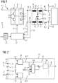
- a converter unit 1 has an inverter 2. On the input side, the converter 2 is supplied with a high potential U + and a low potential U-.
- the potentials U +, U- are usually time-invariant. But you can also vary significantly. However, it must be ensured that the high potential U + is always higher than the low potential U-.
- the potentials U +, U- can be supplied to the converter unit 1 from the outside. In general, however, they are generated within the converter unit 1, for example by rectifying a single-phase or multi-phase AC voltage of a larger electrical supply network. In this case, the converter unit 1 is designed as a converter unit with a DC voltage intermediate circuit.
- the converter 2 has a number of phase units 3.
- the phase units 3 each have two switching elements 4, which are connected in series. Between the two switching elements 4 of the respective phase unit 3, a respective phase line 5 is connected. Via the respective phase unit 3, the converter 2 alternately switches one of the potentials U +, U- to the phase lines 5, thereby feeding phase currents I1, I2 into the phase lines 5.
- Each phase has one (1) phase unit 3 and consequently also one (1) phase line 4 per phase.
- the switching elements 4 are in FIG. 1 represented as IGBTs. This embodiment is common.
- the switching elements 4 is usually connected in parallel with a freewheeling diode.
- the freewheeling diodes are in FIG. 1 not shown.
- the number of phases is in the embodiment according to FIG. 1 at two, ie at the minimum number of phases.
- the converter unit 1 furthermore has a filter device 6.
- the filter device 6 is arranged downstream of the inverter 2. About the filter device 6, the phase currents I1, I2 are performed.
- the filter device 6 has per phase line 5 each have a connection point 7, to which a filter capacitor 8 is connected to the respective phase line 5.
- the filter device 6 serves, in particular, to transform the potentials U +, U-, which are connected in pulsed fashion to the phase lines 5, into a sinusoidal profile.
- the corresponding sinusoidal profile is connected to an electrical load 9.
- the load 9 may be a single load. As a rule, however, in the context of the present invention, it is a complex load, i. the load 9 consists of several, individually switchable consumers. Furthermore, a transformer may be present between the filter device 6 and the load 9. However, this is not mandatory.
- the filter device 6 furthermore preferably comprises, upstream of the connection points 7, an inductance 10 arranged in the respective phase line 5. These inductances are referred to below as front inductances 10.
- the filter device 6 furthermore preferably comprises, behind the connection points 7, an inductance 11 arranged in the respective phase line 5. These inductances are referred to below as rear inductances 11.
- the filter device 6 may further include additional elements such as resistors, other capacitors or other inductors.
- the filter device 6 picks up filter currents IC1, IC2 from the phase lines 5.
- the remaining parts of the phase currents I1, I2 are supplied to the filter device 6 of the electrical load 9 as load currents IL1, IL2.
- the converter 2 also has a control device 12.
- the control device 12 controls the converter 2.
- the control device 12 can realize its functionality by a corresponding embodiment in hardware.
- the control device 12 may have corresponding discrete components.
- the control device 12 is designed as a programmable control device.
- the control device 12 is programmed with a control program 13.
- the control program 13 comprises machine code, by means of which the control device 12 is designed such that the control device 12 has the functional units explained below and functionalities implemented. This applies both to the basic functionality of the control device 12 and to the advantageous embodiments of the control device 12.
- control device 12 is controlled by a microprocessor.
- the microprocessor sequentially operates the machine code 14.
- the control device 12 may contain programmable components in which the circuit of these components as such is determined statically by the machine code 14. Typical examples of such devices are FPGAs and PLAs.
- the control device 12 has according to FIG. 2 a control device 15.
- the control device 15 determines the drive signals S for the phase units 3 (more precisely: for the switching elements 4 of the phase units 3) and controls the phase units 3 (more precisely: the switching elements 4 of the phase units 3) accordingly.
- the manner in which the control device 12 determines the drive signals S in the various operating states of the converter unit 1 is the actual subject of the present invention.
- phase currents I1, I2 - ie the currents fed by the phase units 3 in the phase lines 5 and thus the currents flowing through the switching elements 4 - detected.
- the detected phase currents I1, I2 (more precisely: the corresponding measured values) are sent to the control device 12 via corresponding inputs 17 (see FIG FIG. 1 ).
- the control device 12 receives the measured values.
- phase current I1 I2 explained, namely the Phase current I1.
- phase current I2 analogue versions apply.
- the control device 15 comprises in the case of the embodiment according to FIG. 2 a current regulator 15a.
- the current regulator 15a performs a direct current control.
- the current regulator 15a is preceded by a switching device 15b.
- the switching means 15b, the filter current IC1, the associated desired filter current IC1 *, the phase current I1 and a maximum value MAX are supplied.
- the switching device 15b supplies the current regulator 15a with the filter current IC1 as the actual value. Normal operation is when and as long as the amount of the phase current I1 has a minimum distance from the maximum value MAX.
- the setpoint is the associated setpoint filter current IC1 *. It is provided by an associated setpoint generator 25.
- the output signal of the current regulator 15a corresponds to the drive signal S for the corresponding phase unit 3.
- the setpoint value IC1 * is determined such that the profile of the phase voltage U1 behind the filter device 6 has a predetermined amplitude U0, for example approximately 325 V for a standard mains voltage of 230 V effective.
- the desired value IC1 * is furthermore also determined in such a way that the profile of the phase voltage U1 has a sinusoidal profile behind the filter device 6.
- the switching device 15b continuously checks whether the phase current I1 flowing in the phase line 5 (more precisely: its magnitude) is smaller than the maximum value MAX (more precisely: has a minimum distance from the maximum value MAX). As long as this is the case, the normal operation is present. However, as soon as the phase current I1 (or more precisely the amount thereof) reaches the maximum value MAX (or falls below the minimum distance), the switching device 15b switches to the short-circuit mode. In short-circuit operation, the switching device 15b does not supply the current regulator 15a with the actual current value as the filter current IC1, but rather with the phase current I1.
- the phase voltage U1 in the short-circuit operation behind the filter device 6 to an amplitude which is smaller than the predetermined amplitude U0, for example, only about 25 V.
- the switching device 15b checks in short-circuit operation therefore continuously, whether the amplitude of the phase voltage U1 again reaches predetermined amplitude. If this is the case, the switching device 15b switches back to normal operation.
- control device 12 receives the filter current IC1 as a measured variable.
- the filter current IC1 by means of a corresponding current sensor (in the 1 and 2 not shown) directly and supplied to the control device 12 and is the control device 12 thus available.
- control device 12 determines the filter current IC1 on the basis of detected measured variables U1, I1 received by the control device 12.
- phase voltage U1 of the corresponding phase line 5 measured by means of a corresponding voltage sensor 18 (see FIG. 1 ) measured a phase voltage U1 of the corresponding phase line 5.
- the measured or detected phase voltage U1 (more precisely, the corresponding measured value) is as shown in FIG FIG. 2 fed to the control device 12.
- the control device 12 receives the phase voltage U1 via a corresponding input 19.
- phase voltage U1 it is possible for the phase voltage U1 to be measured within the filter device 6, in particular at the connection point 7 of the corresponding phase line 5.
- the phase voltage U1 it is possible for the phase voltage U1 to be measured behind the filter device 6, in particular behind the rear inductance 11.
- the current determination device 20 determines the filter current IC1 model-based on the detected phase voltage U1 and the phase current I1. This will be described below in connection with FIG. 3 explained in more detail.
- the filter device 6 of FIG. 1 can according to the equivalent circuit of FIG. 3 be modeled.
- the rear inductor 11 has a resistance RL and an inductance value L.
- the filter capacitor 8 has a resistance RC and a capacitance value C.
- the phase current I1 and the phase voltage U1 are applied to the in FIG. 3 measured points.
- Equation (5) the resistance values RL and RC, the inductance value L, and the capacitance value C are constants.
- the phase current I1 and the phase voltage U1 are measured and are therefore known.
- the only load remaining in equation (5) remains the load current IL1.
- the differential equation (5) can therefore be solved.
- phase current I1 I2 explained, again here for the phase current I1.
- phase current I2 analogue versions apply again.
- the current regulator 15a is always supplied with the phase current I1, ie both in normal operation and in short-circuit operation.
- the current regulator 15a is further supplied with a desired phase current I1 *.
- phase current I1 is detected directly by measurement and is therefore available.
- the desired phase current I1 * results as the sum of the desired filter current IC1 * and the load current IL1.
- control device 12-in addition to the phase current I1-to receive the load current IL1 or the filter current IC1 as the measured variable.
- the load current IL1 will be directly available directly or after applying equation (1).
- the load current IL1 determined based on the phase current I1 and the phase voltage U1.
- a corresponding current determining device 20 may be present.
- the associated filter current IC1 can be determined. If according to the representation in the FIG. 1 and 3 the phase voltage U1 is tapped behind the filter device 6, as in corresponding application of the embodiments to FIG. 2 by applying equation (5), the associated load current IL1 can be determined.
- the control device 12 also has an addition device 21.
- the addition device 21 receives from the current determination device 20 the load current IL1 determined by it and the desired filter current IC1 *.
- the adder 21 adds the load current IL1 and the target filter current IC1 * and thus determines the target phase current to be provided. This value is only preliminary.
- the adder 21 supplies the provisional target phase current I1 * to a limiting device 22.
- the limiting device 22 limits the desired phase current I1 * (to be more precise its magnitude) to the maximum value MAX.
- the provisional target phase current I1 * output by the adder 21 is between -MAX and + MAX, the limiting means 22 does not change the target phase current I1 *.
- the limiting device 20 limits the desired phase current I1 * to the value -MAX.
- the limiting device 20 limits the desired phase current I1 * to the value + MAX.
- the correspondingly limited and therefore now definitive nominal phase current I1 * leads the limiting device 22 to the control device 15.
- the control device 15 is further supplied to the detected phase current I1.
- the control device 15 determines the drive signals S for the phase units 3 based on the limited to the maximum value MAX desired phase current I1 * and the phase current I1. It also carries out a direct current regulation here.
- the control device 15 decides directly without intervening determination of a target voltage based on the deviation of the phase current I1 from the target phase current I1 *, which is the potentials U +, U- respectively connected to the phase lines 5.
- the respective phase line 5 is always temporarily separated from the corresponding potential U +, U- as soon as the magnitude of the phase current I1 flowing in the respective phase line 5 reaches the maximum value MAX.
- the method for determining the drive signals S is maintained unchanged, but the setpoint I1 * is limited for the corresponding phase current I1.
- the corresponding potential U +, U- is switched on again automatically to the corresponding phase line 5.
- Compliance with the minimum distance from the maximum value is achieved here by the direct current regulation itself, since this has a hysteresis behavior.
- the switching device 15b and the limiting device 22 engage in the activation of the phase units 3 such that the amounts of the phase currents I1, I2, I3 fed into the phase lines 5 are at the maximum value MAX until the voltage profile U1 caused by the activation of the phase units 3 behind the Filter device 6 again has the predetermined amplitude U0.
- the current control can be a two-step control.
- Two-point control in this context means that one of the two phase lines 5 is always connected to the high potential U +, the other one to the low potential U-.
- phase lines 5 can also be connected to the same potential U +, U-.
- phase current I1 and the further measured variable - ie either the filter current IC1 or the phase voltage U1 - are detected at certain times. The times can coincide. However, this is not necessarily the case. If the points of time fall apart, on the one hand, the later acquired measured variable must be recalculated to the time of the previously acquired measured variable. On the other hand, the determination of the load current IL1 results in a delay. To compensate for this delay, the current detection device 20, therefore, as shown in FIG FIG. 5 Preferably, a computing device 23 and an extrapolation 24 on.
- the computing device 23 determines a filter current IC1 'or a load current IL1' for a time at which the measured variables, by means of which the filter current IC1 'or the load current IL1' is determined, are detected. In exceptional cases, the measured variables are the associated phase current I1 and the associated filter current IC1 and, as a rule, the associated phase current I1 and the associated phase voltage U1.
- the computing device 23 supplies the filter current IC1 'or load current IL1' of the extrapolation device 24 determined by it.
- the extrapolator 24 modifies the filter current supplied to it IC1 'or load current IL1'.
- the modification is such that the filter current IC1 'or load current IL1' supplied to the extrapolator 24 is extrapolated with respect to a nominal frequency of the phase voltage U1 (typically 50 Hz or 60 Hz) by an extrapolation time.
- the switching device 15b in the case of the embodiment according to FIG. 2 ) or the adder 21, the correspondingly extrapolated current IC1 'or IL1' is then supplied.
- the extrapolation with respect to the nominal frequency is based on the consideration that the filter current IC1 and the load current IL1 usually oscillate more or less sinusoidally with the nominal frequency. Furthermore, since the past history of the filter current IC1 'or of the load current IL1' is known from the past, a desired extrapolation time can be related to the period of the phase voltage U1 and the filter current IC1 or the load current IL1 'extrapolated by the extrapolation time become. The correspondingly extrapolated value then corresponds to the filter current IC1 or the load current IL1 which the extrapolation device 24 supplies to the switching device 15b or to the adder 21.
- the determination of the desired filter current IC1 * must be stabilized.
- Errors in the determination of the load current IL1 for example due to component tolerances, measurement errors or the calculation accuracy in determining the load current IL1 cause a initial error gets bigger and bigger over time. Similar problems arise in the case of the embodiment according to FIG. 2 ,
- the setpoint generator 25 may be designed as a voltage regulator.
- the setpoint generator 25 is fed as actual value, the measured phase voltage U1.
- the setpoint generator 25 is supplied with the associated desired phase voltage U1 *.
- the setpoint generator 25 determines the setpoint filter current IC1 * based on the measured phase voltage U1 and the setpoint phase voltage U1 *.
- the phase voltage U1 is detected.
- the desired phase voltage U1 * can be readily provided as a function of time.
- a conversion of the detected phase voltage U1 in a co-rotating system are known in three-phase applications, for example as dq systems. The conversion is also well known to experts.
- the setpoint generator 25 comprises (as setpoint generator for the setpoint filter current IC1 *) two separate controllers to which constant values are supplied as voltage setpoint values, for example the setpoint amplitude U0 and the value 0.
- the output signals continue to be the two separate controllers in a further conversion block 27 reunited and converted into the non-co-rotating output system.
- the setpoint generator 25 is in the case of the embodiment according to FIG. 6 a controller that has an integral component or shows an integrating behavior.
- the setpoint generator 25 may be formed as a PI controller.
- FIG. 6 underlying case, in which the inverter 2 operates a two-phase voltage system, a single Setpoint generator 25 be sufficient for both phases, since the phase voltage U between the two phases can be measured.
- the dynamics of the setpoint generator 25 is usually relatively low. In most cases, the setpoint generator 25 requires two to four periods of the desired phase voltage U1 * - in particular approximately three periods - in order to correct an occurring disturbance. To improve the dynamics in the leadership behavior, the controller 12 therefore, as shown in FIG. 6 Preferably, a pilot control device 28.
- the pre-control device 28, the target phase voltage U1 * (or the desired amplitude U0) is supplied.
- the pilot control device 28 determines based on the desired phase voltage U1 * a pilot control value IC1V for the target filter current IC1 *.
- the precontrol value IC1V is applied to the setpoint filter current IC1 * determined by the setpoint generator 25.
- the resulting desired filter current which is supplied to the adder 21, thus results in this case as the sum of the setpoint filter current IC1 * determined by the voltage regulator 25 and the pilot control value IC1V determined by the pilot control device 28.
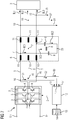
- the neutral point 29 can be related to the potential U +, U- present on the input side of the converter 2. Alternatively it can be U +, U - floating and variable with respect to the potentials. Alternatively, the Filter capacitors 8 as shown in FIG. 8 Connect each of the two phases in the manner of a delta connection. The remaining remarks to the 1 to 6 are also for the embodiments according to the FIG. 7 and 8th valid. It is only to be noted that the corresponding configurations and measures have to be implemented and taken coordinated for each phase. As far as conversions from a delta connection to a star connection and vice versa must be made, these conversions are well known to those skilled in the art. They will therefore not be further explained below.
- Freewheeling diodes are present in the FIG. 7 and 8th are not shown. If the number of phases is at least three (usually exactly three), however, further embodiments of the control device 12 are possible and useful. The embodiments are in the 9, 10 and 11 each represented for a single phase. However, they are to be taken for all phases and are therefore explained for all phases.
- the control device 12 may have a voltage determination device 30 in this case.
- the voltage determination device 30 accepts the detected phase voltages U1, U2, U3 for the phases. It determines, separately for each phase, an amplitude U1M, U2M, U3M related to the star point 29.
- the voltage determination device 30 can detect the phase voltages U1, U2, U3 sufficiently frequently over an entire number of periods and evaluate the detected voltage values.
- the reference to the star point 29 is known to those skilled in the art.
- the voltage determining device 30-separately for each phase-can for example approximate the detected voltage values with a sine of the rated frequency or determine an RMS value (RMS root mean square) on the basis of the detected voltage values.
- the ascertained amplitudes U1M, U2M, U3M supply the voltage determination device 30 to an averaging device 31.
- the mean value generator 31 forms the mean value UM of the determined amplitudes U1M, U2M, U3M.
- the control device 12 also has an amplitude controller 32 for the phases.
- the amplitude controller 32 is supplied with the respective amplitude U1M, U2M, U3M as the actual value and the mean value UM of the amplitudes U1M, U2M, U3M as the desired value.
- the mean value UM thus represents the common setpoint value for the amplitude controllers 32.
- the amplitude controllers 32 determine as shown in FIG. 9 based on their respective actual value - for example, the amplitude U1M - and the target value UM, a respective first correction value k11, k12, k13 for the respective target filter current IC1 *, IC2 *, IC3 *.
- the respective first correction value k11, k12, k13 and the respective desired filter current IC1 *, IC2 *, IC3 * are supplied to a respective first correction block 33, which outputs the respective desired filter current IC1 *, IC2 *, IC3 * by the respective first correction value k11, k12, k13 corrected.
- the correction can be realized in particular by multiplying the respective desired filter current IC1 *, IC2 *, IC3 * by the respective first correction value k11, k12, k13.
- the amplitude regulators 32 are - analogous to the voltage regulators 25 - controllers which have an integral component or show an integrating behavior.
- the amplitude controllers 32 may be designed as (pure) integral controllers.
- the voltage determination device 30 not only determines the amplitudes U1M, U2M *, U3M of the phase voltages U1, U2, U3, but also carries out further determinations.
- the voltage determination device 30 as shown in FIG. 10
- the phase voltages U1, U2, U3 also each determine a respective DC voltage component G1, G2, G3.
- the DC voltage components G1, G2, G3 are related to the neutral point 29.
- the voltage determination device 30 can detect the phase voltages U1, U2, U3 sufficiently frequently over an entire number of periods and the detected voltage values evaluate.
- the reference to the star point 29 is known to those skilled in the art.
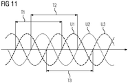
- the voltage determining device 30 can repeatedly detect the respective phase voltage U1, U2, U3 during a respective detection period T1, T2, T3 and, separated for each phase, the respective mean value of the detected phase voltages U1, U2, Form U3.
- the detection periods T1, T2, T3 each form a whole number of periods for the respective phase voltage U1, U2, U3.
- the acquisition periods T1, T2, T3 for the phase voltages U1, U2, U3 can be chosen arbitrarily. In particular, they can be determined uniformly.
- the controller 12 determines the detection periods T1, T2, T3 as shown in FIG FIG. 11 but individually and independently.
- the control device 12 can determine the respective detection period T1, T2, T3 such that the respectively first detection of a respective phase voltage U1, U2, U3 takes place immediately after the zero crossing of the respective phase voltage U1, U2, U3.
- the zero crossing is usually related to the real or virtual potential of the neutral point 29.
- the control device 12 In the case of determining the DC voltage components G1, G2, G3, the control device 12 according to FIG. 10 for each of the phases in each case an offset controller 34.
- the respective offset controller 34 receives the respective DC voltage component G1, G2, G3. Based on the respective DC voltage component G1, G2, G3, it determines a respective second correction value k21, k22, k23 for the respective desired filter current IC1 *, IC2 *, IC3 *.
- the respective second correction value k21, k22, k23 and the respective respective reference filter current IC1 *, IC2 *, IC3 * corrected by the first correction value k11, k12, k13 are supplied to a respective second correction block 35, which supplies the respective desired correction current.
- the correction can be made in particular by adding the respective Target filter current IC1 *, IC2 *, IC3 * and the respective second correction value k21, k22, k23 be realized.
- the offset controllers 34 are - analogous to the voltage regulators 25 and the amplitude regulators 32 - controllers which have an integral component or show an integrating behavior.
- the offset controller 34 may be formed as (pure) integral controller.
- the dynamics of the offset controller 34, the amplitude controller 32 and the setpoint generator 25 should be coordinated.
- the setpoint generator 25 should have the greatest dynamics.
- the dynamics of the offset controller 34 and the amplitude controller 32 should therefore be less than that of the setpoint generator 25.
- the offset controller 34 has a dynamic which is greater than the dynamics of the amplitude controller 32.
- the offset controller 34 should react three to five times as fast to a fault as the amplitude controller 32. Compared to the setpoint generator 25 but their dynamics should be about 1/3 to 2/3.
- the present invention has many advantages. Due to the direct current control, which works both in normal operation and in short-circuit operation, no switching from a voltage regulation to a current regulation is required in the event of a short circuit. This can avoid transient disturbances that would otherwise occur. Nevertheless, in particular short-circuit currents can be dynamically provided and limited. It is a simple transition from an off-grid operation to a network parallel operation and vice versa possible. Even at the current limit of the inverter 2, a stable operation is possible. Furthermore, the control device 12 according to the invention can also be used in conjunction with a load 9, which dynamically - for example when switching - although for a certain time an increased power consumption, but then again requires less power. An example of such a load 9 is a larger asynchronous machine.
- phase voltages U1, U2, U3 It can be achieved in normal operation, a high quality in the provision of the phase voltages U1, U2, U3. This applies regardless of whether the load 9 is linear or non-linear and / or whether the load 9 is symmetrical or asymmetrical. Furthermore, the procedure according to the invention is not restricted to a specific coordinate system.
Priority Applications (5)
| Application Number | Priority Date | Filing Date | Title |
|---|---|---|---|
| EP18157423.7A EP3528375A1 (fr) | 2018-02-19 | 2018-02-19 | Convertisseur stable en court-circuit à commande de courant directe |
| PCT/EP2019/052976 WO2019158422A1 (fr) | 2018-02-19 | 2019-02-07 | Convertisseur protégé contre les court-circuits et pourvu d'une commande de courant continu |
| CN201980014033.2A CN111742476B (zh) | 2018-02-19 | 2019-02-07 | 具有直接电流控制的抗短路变流器 |
| US16/970,877 US11005357B2 (en) | 2018-02-19 | 2019-02-07 | Short-circuit-proof inverter having a direct current control |
| EP19706896.8A EP3714539B1 (fr) | 2018-02-19 | 2019-02-07 | Convertisseur stable en court-circuit à commande de courant directe |
Applications Claiming Priority (1)
| Application Number | Priority Date | Filing Date | Title |
|---|---|---|---|
| EP18157423.7A EP3528375A1 (fr) | 2018-02-19 | 2018-02-19 | Convertisseur stable en court-circuit à commande de courant directe |
Publications (1)
| Publication Number | Publication Date |
|---|---|
| EP3528375A1 true EP3528375A1 (fr) | 2019-08-21 |
Family
ID=61244474
Family Applications (2)
| Application Number | Title | Priority Date | Filing Date |
|---|---|---|---|
| EP18157423.7A Withdrawn EP3528375A1 (fr) | 2018-02-19 | 2018-02-19 | Convertisseur stable en court-circuit à commande de courant directe |
| EP19706896.8A Active EP3714539B1 (fr) | 2018-02-19 | 2019-02-07 | Convertisseur stable en court-circuit à commande de courant directe |
Family Applications After (1)
| Application Number | Title | Priority Date | Filing Date |
|---|---|---|---|
| EP19706896.8A Active EP3714539B1 (fr) | 2018-02-19 | 2019-02-07 | Convertisseur stable en court-circuit à commande de courant directe |
Country Status (4)
| Country | Link |
|---|---|
| US (1) | US11005357B2 (fr) |
| EP (2) | EP3528375A1 (fr) |
| CN (1) | CN111742476B (fr) |
| WO (1) | WO2019158422A1 (fr) |
Families Citing this family (1)
| Publication number | Priority date | Publication date | Assignee | Title |
|---|---|---|---|---|
| DE102019112598A1 (de) * | 2019-05-14 | 2020-11-19 | Dr. Johannes Heidenhain Gmbh | Hochfrequenz-Netzfilter |
Citations (1)
| Publication number | Priority date | Publication date | Assignee | Title |
|---|---|---|---|---|
| US20150036397A1 (en) * | 2013-08-01 | 2015-02-05 | Fsp-Powerland Technology Inc. | Inverter and over current protection method thereof |
Family Cites Families (14)
| Publication number | Priority date | Publication date | Assignee | Title |
|---|---|---|---|---|
| DE3685190D1 (de) * | 1985-10-21 | 1992-06-11 | Mitsubishi Electric Corp | Konstante spannungs-/frequenzleistungsversorgungseinrichtung. |
| JP2783555B2 (ja) * | 1988-09-26 | 1998-08-06 | 株式会社東芝 | 電力変換装置 |
| US5757099A (en) * | 1996-03-01 | 1998-05-26 | Wisconsin Alumni Research Foundation | Hybrid parallel active/passive filter system with dynamically variable inductance |
| JP2001112262A (ja) * | 1999-10-05 | 2001-04-20 | Kokusan Denki Co Ltd | 電力変換回路付き電源装置及びその制御方法 |
| EP1220432A3 (fr) * | 2000-12-19 | 2003-01-29 | Fuji Electric Co., Ltd. | Disposition de réduction de bruit dans un système de conversion d'énergie électrique |
| US20120262079A1 (en) * | 2010-03-04 | 2012-10-18 | Yung-Lin Lin | Circuits and methods for driving light sources |
| US10090777B2 (en) * | 2011-05-08 | 2018-10-02 | Koolbridge Solar, Inc. | Inverter with independent current and voltage controlled outputs |
| US9667128B2 (en) * | 2012-04-30 | 2017-05-30 | Rockwell Automation Technologies, Inc. | Power converter resonance detection apparatus and method |
| US9653984B2 (en) * | 2012-04-30 | 2017-05-16 | Rockwell Automation Technologies, Inc. | Filter capacitor degradation detection apparatus and method |
| JP6342293B2 (ja) * | 2014-10-20 | 2018-06-13 | 株式会社東芝 | 中性点クランプ形電力変換装置およびその制御方法 |
| CN104578082B (zh) * | 2014-12-29 | 2018-05-22 | 南京航空航天大学 | 动态电压校正装置、校正方法及负载短路故障的隔离方法 |
| DE102015101766A1 (de) * | 2015-02-06 | 2016-08-11 | Woodward Kempen Gmbh | Filterüberwachung |
| CN106100359A (zh) * | 2016-06-28 | 2016-11-09 | 中车青岛四方车辆研究所有限公司 | 交‑直‑交型动车组辅助变流器及其工作过程 |
| CN106972471A (zh) * | 2017-04-27 | 2017-07-21 | 国家电网公司 | 多功能短路电流限制器 |
-
2018
- 2018-02-19 EP EP18157423.7A patent/EP3528375A1/fr not_active Withdrawn
-
2019
- 2019-02-07 EP EP19706896.8A patent/EP3714539B1/fr active Active
- 2019-02-07 CN CN201980014033.2A patent/CN111742476B/zh active Active
- 2019-02-07 WO PCT/EP2019/052976 patent/WO2019158422A1/fr active Search and Examination
- 2019-02-07 US US16/970,877 patent/US11005357B2/en active Active
Patent Citations (1)
| Publication number | Priority date | Publication date | Assignee | Title |
|---|---|---|---|---|
| US20150036397A1 (en) * | 2013-08-01 | 2015-02-05 | Fsp-Powerland Technology Inc. | Inverter and over current protection method thereof |
Non-Patent Citations (2)
| Title |
|---|
| BOTTRELL NATHANIEL ET AL: "Comparison of Current-Limiting Strategies During Fault Ride-Through of Inverters to Prevent Latch-Up and Wind-Up", IEEE TRANSACTIONS ON POWER ELECTRONICS, INSTITUTE OF ELECTRICAL AND ELECTRONICS ENGINEERS, USA, vol. 29, no. 7, 1 July 2014 (2014-07-01), pages 3786 - 3797, XP011540339, ISSN: 0885-8993, [retrieved on 20140217], DOI: 10.1109/TPEL.2013.2279162 * |
| MUKHERJEE SUBHAJYOTI ET AL: "Filter capacitor current estimation and grid current control in LCL based grid connected inverter", 2017 IEEE ENERGY CONVERSION CONGRESS AND EXPOSITION (ECCE), IEEE, 1 October 2017 (2017-10-01), pages 3885 - 3889, XP033247329, DOI: 10.1109/ECCE.2017.8096683 * |
Also Published As
| Publication number | Publication date |
|---|---|
| US11005357B2 (en) | 2021-05-11 |
| EP3714539A1 (fr) | 2020-09-30 |
| CN111742476B (zh) | 2021-08-31 |
| CN111742476A (zh) | 2020-10-02 |
| WO2019158422A1 (fr) | 2019-08-22 |
| EP3714539B1 (fr) | 2022-03-30 |
| US20210050770A1 (en) | 2021-02-18 |
Similar Documents
| Publication | Publication Date | Title |
|---|---|---|
| DE3917337C2 (fr) | ||
| EP2614573B1 (fr) | Procédé de stabilisation d'un réseau d'alimentation électrique | |
| AT403865B (de) | Spannungsumsetzungsvorrichtung für einen gleichspannungsverbraucher | |
| DE19909464C2 (de) | Verfahren zur Erzeugung einer geregelten Gleichspannung aus einer Wechselspannung und Stromversorgungseinrichtung zur Durchführung des Verfahrens | |
| DE112013006680T5 (de) | Dreiphasen-Spannungs-Umsetzungsvorrichtung | |
| DE4206263A1 (de) | Steuergeraet fuer stern- oder nullpunkt-angeklammerten leistungs- oder stromumformer | |
| DE19612920A1 (de) | Verfahren und Vorrichtung zur direkten Drehmomentregelung einer Drehfeldmaschine | |
| DE2246505C3 (de) | Schaltungsanordnung zur unterbrechungsfreien Stromversorgung eines Gleichstromverbauchers mit konstanter Spannung | |
| EP2436092A2 (fr) | Dispositif de compensation d'harmoniques | |
| WO2019077059A1 (fr) | Procédé permettant de déterminer un défaut de tension d'un convertisseur ainsi que machine à induction munie d'une compensation des défauts de tension | |
| EP3714539B1 (fr) | Convertisseur stable en court-circuit à commande de courant directe | |
| EP2068416B1 (fr) | Précommande d'un convertisseur de source de tension | |
| DE19605419B4 (de) | Verfahren zur Beseitigung von Abweichungen der Ist-Spannung in einem Drehstromnetz von einer vorgegebenen Soll-Spannung | |
| EP2985896A1 (fr) | Systeme d'accentuation du facteur de puissance cote reseau de moteurs ec triphases | |
| DE102012221670A1 (de) | DC/DC-Wandler mit wirkungsgradgeführter Anpassung der Arbeitsfrequenz | |
| DE1162471B (de) | Schutzeinrichtung fuer Wechselstromnetze | |
| EP3459165B1 (fr) | Convertisseur et procédé de fonctionnement de celui-ci | |
| EP0865138A1 (fr) | Procédé et dispositif pour la formation d'une tension alternative | |
| DE2151019B2 (de) | Verfahren zur regelung des einem wechselstromnetz entnommenen oder zugefuehrten stromes und anordnung zur durchfuehrung des verfahrens | |
| DE686021C (de) | Einrichtung zur UEberlagerung von Wechselstromenergieverteilungsnetzen mit Schwachstroemen netzfremder Frequenz | |
| EP3379679A1 (fr) | Système d'alimentation en énergie électrique | |
| DE19942203B4 (de) | Verfahren zur Ausgangsspannungsbegrenzung für einen spannungs-/frequenzgeführten Umrichter | |
| EP3520213B1 (fr) | Procédé destiné au fonctionnement d'un onduleur et onduleur | |
| DE2017933C3 (de) | Stromrichteranlage | |
| DE19856551A1 (de) | Verfahren und Schaltungsanordnung zur Anpassung der Zwischenkreisspannung an die Versorgungsspannung |
Legal Events
| Date | Code | Title | Description |
|---|---|---|---|
| PUAI | Public reference made under article 153(3) epc to a published international application that has entered the european phase |
Free format text: ORIGINAL CODE: 0009012 |
|
| AK | Designated contracting states |
Kind code of ref document: A1 Designated state(s): AL AT BE BG CH CY CZ DE DK EE ES FI FR GB GR HR HU IE IS IT LI LT LU LV MC MK MT NL NO PL PT RO RS SE SI SK SM TR |
|
| AX | Request for extension of the european patent |
Extension state: BA ME |
|
| STAA | Information on the status of an ep patent application or granted ep patent |
Free format text: STATUS: THE APPLICATION IS DEEMED TO BE WITHDRAWN |
|
| 18D | Application deemed to be withdrawn |
Effective date: 20200222 |