EP3528375A1 - Short circuit-resistant converter with direct current control - Google Patents
Short circuit-resistant converter with direct current control Download PDFInfo
- Publication number
- EP3528375A1 EP3528375A1 EP18157423.7A EP18157423A EP3528375A1 EP 3528375 A1 EP3528375 A1 EP 3528375A1 EP 18157423 A EP18157423 A EP 18157423A EP 3528375 A1 EP3528375 A1 EP 3528375A1
- Authority
- EP
- European Patent Office
- Prior art keywords
- phase
- currents
- filter
- control device
- load
- Prior art date
- Legal status (The legal status is an assumption and is not a legal conclusion. Google has not performed a legal analysis and makes no representation as to the accuracy of the status listed.)
- Withdrawn
Links
Images


Classifications
-
- H—ELECTRICITY
- H02—GENERATION; CONVERSION OR DISTRIBUTION OF ELECTRIC POWER
- H02M—APPARATUS FOR CONVERSION BETWEEN AC AND AC, BETWEEN AC AND DC, OR BETWEEN DC AND DC, AND FOR USE WITH MAINS OR SIMILAR POWER SUPPLY SYSTEMS; CONVERSION OF DC OR AC INPUT POWER INTO SURGE OUTPUT POWER; CONTROL OR REGULATION THEREOF
- H02M1/00—Details of apparatus for conversion
- H02M1/32—Means for protecting converters other than automatic disconnection
-
- H—ELECTRICITY
- H02—GENERATION; CONVERSION OR DISTRIBUTION OF ELECTRIC POWER
- H02M—APPARATUS FOR CONVERSION BETWEEN AC AND AC, BETWEEN AC AND DC, OR BETWEEN DC AND DC, AND FOR USE WITH MAINS OR SIMILAR POWER SUPPLY SYSTEMS; CONVERSION OF DC OR AC INPUT POWER INTO SURGE OUTPUT POWER; CONTROL OR REGULATION THEREOF
- H02M7/00—Conversion of ac power input into dc power output; Conversion of dc power input into ac power output
- H02M7/42—Conversion of dc power input into ac power output without possibility of reversal
- H02M7/44—Conversion of dc power input into ac power output without possibility of reversal by static converters
- H02M7/48—Conversion of dc power input into ac power output without possibility of reversal by static converters using discharge tubes with control electrode or semiconductor devices with control electrode
- H02M7/53—Conversion of dc power input into ac power output without possibility of reversal by static converters using discharge tubes with control electrode or semiconductor devices with control electrode using devices of a triode or transistor type requiring continuous application of a control signal
- H02M7/537—Conversion of dc power input into ac power output without possibility of reversal by static converters using discharge tubes with control electrode or semiconductor devices with control electrode using devices of a triode or transistor type requiring continuous application of a control signal using semiconductor devices only, e.g. single switched pulse inverters
- H02M7/5387—Conversion of dc power input into ac power output without possibility of reversal by static converters using discharge tubes with control electrode or semiconductor devices with control electrode using devices of a triode or transistor type requiring continuous application of a control signal using semiconductor devices only, e.g. single switched pulse inverters in a bridge configuration
- H02M7/53871—Conversion of dc power input into ac power output without possibility of reversal by static converters using discharge tubes with control electrode or semiconductor devices with control electrode using devices of a triode or transistor type requiring continuous application of a control signal using semiconductor devices only, e.g. single switched pulse inverters in a bridge configuration with automatic control of output voltage or current
-
- H—ELECTRICITY
- H02—GENERATION; CONVERSION OR DISTRIBUTION OF ELECTRIC POWER
- H02M—APPARATUS FOR CONVERSION BETWEEN AC AND AC, BETWEEN AC AND DC, OR BETWEEN DC AND DC, AND FOR USE WITH MAINS OR SIMILAR POWER SUPPLY SYSTEMS; CONVERSION OF DC OR AC INPUT POWER INTO SURGE OUTPUT POWER; CONTROL OR REGULATION THEREOF
- H02M7/00—Conversion of ac power input into dc power output; Conversion of dc power input into ac power output
- H02M7/66—Conversion of ac power input into dc power output; Conversion of dc power input into ac power output with possibility of reversal
- H02M7/68—Conversion of ac power input into dc power output; Conversion of dc power input into ac power output with possibility of reversal by static converters
- H02M7/72—Conversion of ac power input into dc power output; Conversion of dc power input into ac power output with possibility of reversal by static converters using discharge tubes with control electrode or semiconductor devices with control electrode
- H02M7/79—Conversion of ac power input into dc power output; Conversion of dc power input into ac power output with possibility of reversal by static converters using discharge tubes with control electrode or semiconductor devices with control electrode using devices of a triode or transistor type requiring continuous application of a control signal
- H02M7/797—Conversion of ac power input into dc power output; Conversion of dc power input into ac power output with possibility of reversal by static converters using discharge tubes with control electrode or semiconductor devices with control electrode using devices of a triode or transistor type requiring continuous application of a control signal using semiconductor devices only
Definitions
- the present invention is further based on a control program for a programmable controller for an inverter, wherein the control program comprises machine code, by which the control device is formed in such a way.
- Inverter and the associated control devices are well known. They usually operate on the principle that the control device determines the control signals for the phase units of the converter on the basis of phase voltages occurring inside or behind the filter device in conjunction with desired phase voltages.
- the control signals can be determined, for example, such that a pulse-width-modulated control of the phase units takes place.
- the appropriate procedure is generally known to experts. It is usually done by means of a so-called space vector modulation. With these procedures, the phase voltages supplied to the load can be controlled to a few volts exactly.
- phase currents set free. As a result, they are determined by the load. This is problem-free, as long as the phase currents that occur are below a maximum permissible maximum value. However, if this maximum value is reached or exceeded, the inverter in the prior art must be very be shut down quickly to protect it from destruction. In the converters of the prior art, therefore, the phase currents flowing on the output side of the converter are furthermore detected and accepted by the control device. If the phase currents exceed a predetermined maximum value-for example because a short circuit has occurred in the load-the converter is switched off.
- the inverter works very well, if by means of the inverter only a single, singular load is supplied with electrical energy, for example a single drive.
- the inverter is intended to supply a so-called off-grid with electrical energy, i. all consumers located within the corresponding island grid. If, in such a case, a short circuit occurs in one of the consumers and thus an increased current flow, it is still possible in principle to switch off the converter in this case. However, this means that not only the defective consumer is switched off, but all consumers of the island grid.
- the individual consumers or groups of consumers shutdown elements such as fuses or circuit breakers are preceded, interrupt the current flow from the inverter to the respective consumer or to the respective group of consumers in the event of a short circuit.
- the inverter itself is not switched off.
- the remaining part of the island grid is thus still supplied by the inverter with electrical energy.
- phase currents fed into the phase lines must be suitably limited.
- the phase currents must be so high that the switch-off element, which is upstream of the defective consumer, reliably switches off.
- the inverter must therefore continue to operate with a reduced output voltage. This reduced output voltage must be determined in such a way that the converter on the one hand supplies the correspondingly high phase currents, so that the turn-off element triggers, the other hand, the converter is not damaged by the high phase currents.
- the object of the present invention is to provide means by which in a simple and efficient manner, both a normal operation of the inverter (ie the phase voltages lie with minor deviations in their setpoints and the injected phase currents are below the maximum value) as well as a short-circuit operation (ie the phase voltages are limited to values below their setpoints, so that the phase currents fed into the phase lines do not rise above the maximum value) can be realized.
- a simple and trouble-free switching between normal operation and short-circuit operation should be possible.
- Control device with the features of claim 1.
- Advantageous embodiments of Control device are subject of the dependent claims 2 to 15.
- the direct current control can operate, for example, in the manner of a two-point controller: It is defined for the currents to be regulated in each case an interval around the respective target current, within which the respective actual current should be. If the respective actual current reaches or falls below the upper or lower limit of the interval, the drive of the inverter is triggered in each case changed accordingly.
- the input-side potential connected to the respective phase line can, for example, be changed by the respective phase unit.
- control there are also other types of control conceivable.
- it is also possible to change the potential applied to these phase lines in the case of the other phase lines. Because it is important to reduce the potential difference ( the voltage) between the individual phases.
- Either the potential in one phase line can be adapted to the potentials in the other phase lines, or the potentials in the other phase lines can be adapted to the potential in the one phase line.
- a known and also applicable current control method is, for example, the so-called SDHC method.
- SDHC stands for Switched Diamond Hysteresis Control.
- the filter device comprises - in addition to the filter capacitors - preferably in front of and behind the connection points each arranged in the respective phase line inductance. But there are also other embodiments of the filter device possible.
- the inverter operates only a single-phase AC voltage system.
- the inverter has two phase lines.
- the inverter operates a three-phase system with at least three phases, usually exactly three phases.
- the filter capacitors can either be connected to two phase lines in the manner of a delta connection or have a common star point in the manner of a star connection.
- the potential of the star point may alternatively be fixed relative to the input-side potentials or be floating and variable with respect to these potentials.
- the control device accepts the filter streams themselves as measured variables.
- a direct current measurement has the disadvantage that the corresponding current measuring device is relatively expensive.
- the control device therefore preferably determines the filter flows on the basis of detected measured variables and received by the control device.
- phase voltages of the phase lines which are measured inside or behind the filter device can be considered as further measured variables.
- the filter currents can be determined, at least in some cases, directly from the detected phase voltages.
- the filter currents can be modeled based on the detected phase voltages and the phase currents detected on the output side of the inverter.
- This operating mode is also based on the consideration that in normal operation, the time profile of the phase voltages is known and thus the time course of the filter currents is known. By specifying the associated time profiles of the desired filter currents in combination with the determined load currents, the setpoint values for the current control can thus be provided.
- the control device directly accepts the filter streams as further measured variables.
- a direct current measurement has the disadvantage that the corresponding current measuring device is relatively expensive.
- the control device therefore preferably receives phase voltages of the phase lines, which are detected within or behind the filter device, as further measured variables. If the phase voltages are detected within the filter device, the current determination device can determine the filter currents-at least in some cases-directly on the basis of the detected phase voltages. The load currents can then be determined from the filter currents in conjunction with the phase currents. When the phase voltages are sensed downstream of the filter device, the load currents are modeled based on the detected phase voltages and the phase currents detected on the output side of the drive.
- the control device has a computing device and an extrapolation device.
- the computing device determines the filter currents or the load currents supplied to the load. The determination is made for a point in time at which the measured variables, by means of which the filter currents or the load currents are determined, are detected.
- the computing device supplies the filter currents or load currents determined by it to the extrapolation device.
- the extrapolator modifies the filter currents or load currents supplied to it in such a way that they are extrapolated with respect to a nominal frequency of the phase voltages by an extrapolation time.
- the extrapolation device then supplies the filter streams modified by it to the switching device or load currents of the addition device.
- the extrapolation time is suitably determined. In particular, it is determined in such a way that the modifications - based on a previously known nominal frequency of the phase voltages - reflect the corresponding temporal change of the filter currents.
- the extrapolation means modifies the measured quantities by means of which the filter currents or the load currents supplied to the load are determined in such a way that they are extrapolated with respect to a nominal frequency of the phase voltages by the extrapolation time compared with a time at which the measured variables are detected. It supplies the metrics it modifies to the computing device.
- the computing device determines the filter currents or the load currents on the basis of the modified measured variables supplied to it and supplies the filter currents to the switching device or the load currents to the addition device.
- the control device preferably accepts detected phase voltages of the phase lines within or behind the filter device.
- the setpoint generator for the phases are preferably designed as a voltage regulator to which the detected phase voltages and target phase voltages are supplied and determines the reference filter currents based on the detected phase voltages and the desired phase voltages.
- the setpoint generators are preferably controllers with an integral component, in particular a PI controller. Their dynamics are often relatively low. As a rule, the setpoint value transmitters require 2 to 4 periods, in particular approx. 3 periods, to compensate for a fault. The periods are related to a nominal frequency with which the phase voltages are to oscillate.
- the control device preferably has pilot control devices, to which the desired phase voltages are supplied, and which determine precontrol values for the desired filter currents determined by the setpoint generators on the basis of the desired phase voltages.
- the pilot control values can be switched to the setpoint filter currents determined by the setpoint generators.
- the inverter usually operates a three-phase system.
- the number of phases is therefore at least three.
- the control device preferably has a voltage determination device, which receives the phase voltages of the phase lines detected within or behind the filter device and in each case determines an amplitude related to a star point for the phase voltages.
- the control device for the phases in this case each have an amplitude controller to which the respective amplitude is supplied as the actual value and the mean value of the amplitudes as desired value and the respective first correction value for the respective desired filter current based on its respective actual value and its respective setpoint determined and the respective target filter current corrected by the respective first correction value.
- the determination of the star point related amplitudes is well known to those skilled in the art. In particular, it can also be carried out if (in the case of a delta connection of the filter capacitors) the neutral point is absent or the neutral point is present, but is not related to the input-side potentials.
- the amplitude controllers are usually controllers with integral component, in particular integral controller.
- the voltage determination device for the phase voltages also preferably determines a respective DC voltage component related to the neutral point.
- the control device for the phases in each case an offset controller, which receives the respective DC component and the determined based on the respective DC component a respective second correction value for the respective desired filter current and corrects the respective desired filter current to the determined respective second correction value. This can be achieved that the phase voltages are set offset-free.
- the offset controllers are generally controllers with an integral component, in particular integral controllers.
- the voltage determination device accepts a plurality of detected phase voltages during a respective detection period and determines the respective DC voltage component as its respective mean value.
- the control means determines the respective detection period for the phases individually and independently of the detection periods for the other phases.
- the control device can synchronize the respective detection period with the respective zero crossing of the respective phase voltage.
- the dynamics of the various controllers are preferably matched to one another in such a way that the offset controllers have a dynamic which is greater than the dynamics of the amplitude controllers.
- a typical factor in the dynamics is usually between 3 and 5.
- the offset controllers preferably have a dynamic that is less than the dynamics of the setpoint generator.
- a typical factor in dynamics is usually between 1/3 and 2/3.
- the amplitude controllers preferably have a dynamic which is less than the dynamics of the setpoint generator.
- the dynamics of the offset controller is often very small compared to the dynamics of the setpoint generator. A typical factor is between 0.1 and 0.2.
- control device it is possible in principle for the control device to implement its various components in hardware, in particular in the form of ASICs.
- the control device is designed as a programmable control device.
- the control device may be controlled by a microprocessor.
- the control device may include components in which the circuit is defined as such by programming. Typical examples of such devices are FPGAs (Field Programmable Gate Array) and PLA (Programmable Logic Array).
- control device is programmed with a control program.
- the control program comprises in this case machine code, by which the control device is designed as a control device according to the invention.
- control program comprises machine code, by which the control device is designed as a control device according to the invention.
- the control device of the converter unit is designed as a control device according to the invention.
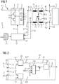
- a converter unit 1 has an inverter 2. On the input side, the converter 2 is supplied with a high potential U + and a low potential U-.
- the potentials U +, U- are usually time-invariant. But you can also vary significantly. However, it must be ensured that the high potential U + is always higher than the low potential U-.
- the potentials U +, U- can be supplied to the converter unit 1 from the outside. In general, however, they are generated within the converter unit 1, for example by rectifying a single-phase or multi-phase AC voltage of a larger electrical supply network. In this case, the converter unit 1 is designed as a converter unit with a DC voltage intermediate circuit.
- the converter 2 has a number of phase units 3.
- the phase units 3 each have two switching elements 4, which are connected in series. Between the two switching elements 4 of the respective phase unit 3, a respective phase line 5 is connected. Via the respective phase unit 3, the converter 2 alternately switches one of the potentials U +, U- to the phase lines 5, thereby feeding phase currents I1, I2 into the phase lines 5.
- Each phase has one (1) phase unit 3 and consequently also one (1) phase line 4 per phase.
- the switching elements 4 are in FIG. 1 represented as IGBTs. This embodiment is common.
- the switching elements 4 is usually connected in parallel with a freewheeling diode.
- the freewheeling diodes are in FIG. 1 not shown.
- the number of phases is in the embodiment according to FIG. 1 at two, ie at the minimum number of phases.
- the converter unit 1 furthermore has a filter device 6.
- the filter device 6 is arranged downstream of the inverter 2. About the filter device 6, the phase currents I1, I2 are performed.
- the filter device 6 has per phase line 5 each have a connection point 7, to which a filter capacitor 8 is connected to the respective phase line 5.
- the filter device 6 serves, in particular, to transform the potentials U +, U-, which are connected in pulsed fashion to the phase lines 5, into a sinusoidal profile.
- the corresponding sinusoidal profile is connected to an electrical load 9.
- the load 9 may be a single load. As a rule, however, in the context of the present invention, it is a complex load, i. the load 9 consists of several, individually switchable consumers. Furthermore, a transformer may be present between the filter device 6 and the load 9. However, this is not mandatory.
- the filter device 6 furthermore preferably comprises, upstream of the connection points 7, an inductance 10 arranged in the respective phase line 5. These inductances are referred to below as front inductances 10.
- the filter device 6 furthermore preferably comprises, behind the connection points 7, an inductance 11 arranged in the respective phase line 5. These inductances are referred to below as rear inductances 11.
- the filter device 6 may further include additional elements such as resistors, other capacitors or other inductors.
- the filter device 6 picks up filter currents IC1, IC2 from the phase lines 5.
- the remaining parts of the phase currents I1, I2 are supplied to the filter device 6 of the electrical load 9 as load currents IL1, IL2.
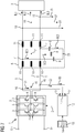
- the converter 2 also has a control device 12.
- the control device 12 controls the converter 2.
- the control device 12 can realize its functionality by a corresponding embodiment in hardware.
- the control device 12 may have corresponding discrete components.
- the control device 12 is designed as a programmable control device.
- the control device 12 is programmed with a control program 13.
- the control program 13 comprises machine code, by means of which the control device 12 is designed such that the control device 12 has the functional units explained below and functionalities implemented. This applies both to the basic functionality of the control device 12 and to the advantageous embodiments of the control device 12.
- control device 12 is controlled by a microprocessor.
- the microprocessor sequentially operates the machine code 14.
- the control device 12 may contain programmable components in which the circuit of these components as such is determined statically by the machine code 14. Typical examples of such devices are FPGAs and PLAs.
- the control device 12 has according to FIG. 2 a control device 15.
- the control device 15 determines the drive signals S for the phase units 3 (more precisely: for the switching elements 4 of the phase units 3) and controls the phase units 3 (more precisely: the switching elements 4 of the phase units 3) accordingly.
- the manner in which the control device 12 determines the drive signals S in the various operating states of the converter unit 1 is the actual subject of the present invention.
- phase currents I1, I2 - ie the currents fed by the phase units 3 in the phase lines 5 and thus the currents flowing through the switching elements 4 - detected.
- the detected phase currents I1, I2 (more precisely: the corresponding measured values) are sent to the control device 12 via corresponding inputs 17 (see FIG FIG. 1 ).
- the control device 12 receives the measured values.
- phase current I1 I2 explained, namely the Phase current I1.
- phase current I2 analogue versions apply.
- the control device 15 comprises in the case of the embodiment according to FIG. 2 a current regulator 15a.
- the current regulator 15a performs a direct current control.
- the current regulator 15a is preceded by a switching device 15b.
- the switching means 15b, the filter current IC1, the associated desired filter current IC1 *, the phase current I1 and a maximum value MAX are supplied.
- the switching device 15b supplies the current regulator 15a with the filter current IC1 as the actual value. Normal operation is when and as long as the amount of the phase current I1 has a minimum distance from the maximum value MAX.
- the setpoint is the associated setpoint filter current IC1 *. It is provided by an associated setpoint generator 25.
- the output signal of the current regulator 15a corresponds to the drive signal S for the corresponding phase unit 3.
- the setpoint value IC1 * is determined such that the profile of the phase voltage U1 behind the filter device 6 has a predetermined amplitude U0, for example approximately 325 V for a standard mains voltage of 230 V effective.
- the desired value IC1 * is furthermore also determined in such a way that the profile of the phase voltage U1 has a sinusoidal profile behind the filter device 6.
- the switching device 15b continuously checks whether the phase current I1 flowing in the phase line 5 (more precisely: its magnitude) is smaller than the maximum value MAX (more precisely: has a minimum distance from the maximum value MAX). As long as this is the case, the normal operation is present. However, as soon as the phase current I1 (or more precisely the amount thereof) reaches the maximum value MAX (or falls below the minimum distance), the switching device 15b switches to the short-circuit mode. In short-circuit operation, the switching device 15b does not supply the current regulator 15a with the actual current value as the filter current IC1, but rather with the phase current I1.
- the phase voltage U1 in the short-circuit operation behind the filter device 6 to an amplitude which is smaller than the predetermined amplitude U0, for example, only about 25 V.
- the switching device 15b checks in short-circuit operation therefore continuously, whether the amplitude of the phase voltage U1 again reaches predetermined amplitude. If this is the case, the switching device 15b switches back to normal operation.
- control device 12 receives the filter current IC1 as a measured variable.
- the filter current IC1 by means of a corresponding current sensor (in the 1 and 2 not shown) directly and supplied to the control device 12 and is the control device 12 thus available.
- control device 12 determines the filter current IC1 on the basis of detected measured variables U1, I1 received by the control device 12.
- phase voltage U1 of the corresponding phase line 5 measured by means of a corresponding voltage sensor 18 (see FIG. 1 ) measured a phase voltage U1 of the corresponding phase line 5.
- the measured or detected phase voltage U1 (more precisely, the corresponding measured value) is as shown in FIG FIG. 2 fed to the control device 12.
- the control device 12 receives the phase voltage U1 via a corresponding input 19.
- phase voltage U1 it is possible for the phase voltage U1 to be measured within the filter device 6, in particular at the connection point 7 of the corresponding phase line 5.
- the phase voltage U1 it is possible for the phase voltage U1 to be measured behind the filter device 6, in particular behind the rear inductance 11.
- the current determination device 20 determines the filter current IC1 model-based on the detected phase voltage U1 and the phase current I1. This will be described below in connection with FIG. 3 explained in more detail.
- the filter device 6 of FIG. 1 can according to the equivalent circuit of FIG. 3 be modeled.
- the rear inductor 11 has a resistance RL and an inductance value L.
- the filter capacitor 8 has a resistance RC and a capacitance value C.
- the phase current I1 and the phase voltage U1 are applied to the in FIG. 3 measured points.
- Equation (5) the resistance values RL and RC, the inductance value L, and the capacitance value C are constants.
- the phase current I1 and the phase voltage U1 are measured and are therefore known.
- the only load remaining in equation (5) remains the load current IL1.
- the differential equation (5) can therefore be solved.
- phase current I1 I2 explained, again here for the phase current I1.
- phase current I2 analogue versions apply again.
- the current regulator 15a is always supplied with the phase current I1, ie both in normal operation and in short-circuit operation.
- the current regulator 15a is further supplied with a desired phase current I1 *.
- phase current I1 is detected directly by measurement and is therefore available.
- the desired phase current I1 * results as the sum of the desired filter current IC1 * and the load current IL1.
- control device 12-in addition to the phase current I1-to receive the load current IL1 or the filter current IC1 as the measured variable.
- the load current IL1 will be directly available directly or after applying equation (1).
- the load current IL1 determined based on the phase current I1 and the phase voltage U1.
- a corresponding current determining device 20 may be present.
- the associated filter current IC1 can be determined. If according to the representation in the FIG. 1 and 3 the phase voltage U1 is tapped behind the filter device 6, as in corresponding application of the embodiments to FIG. 2 by applying equation (5), the associated load current IL1 can be determined.
- the control device 12 also has an addition device 21.
- the addition device 21 receives from the current determination device 20 the load current IL1 determined by it and the desired filter current IC1 *.
- the adder 21 adds the load current IL1 and the target filter current IC1 * and thus determines the target phase current to be provided. This value is only preliminary.
- the adder 21 supplies the provisional target phase current I1 * to a limiting device 22.
- the limiting device 22 limits the desired phase current I1 * (to be more precise its magnitude) to the maximum value MAX.
- the provisional target phase current I1 * output by the adder 21 is between -MAX and + MAX, the limiting means 22 does not change the target phase current I1 *.
- the limiting device 20 limits the desired phase current I1 * to the value -MAX.
- the limiting device 20 limits the desired phase current I1 * to the value + MAX.
- the correspondingly limited and therefore now definitive nominal phase current I1 * leads the limiting device 22 to the control device 15.
- the control device 15 is further supplied to the detected phase current I1.
- the control device 15 determines the drive signals S for the phase units 3 based on the limited to the maximum value MAX desired phase current I1 * and the phase current I1. It also carries out a direct current regulation here.
- the control device 15 decides directly without intervening determination of a target voltage based on the deviation of the phase current I1 from the target phase current I1 *, which is the potentials U +, U- respectively connected to the phase lines 5.
- the respective phase line 5 is always temporarily separated from the corresponding potential U +, U- as soon as the magnitude of the phase current I1 flowing in the respective phase line 5 reaches the maximum value MAX.
- the method for determining the drive signals S is maintained unchanged, but the setpoint I1 * is limited for the corresponding phase current I1.
- the corresponding potential U +, U- is switched on again automatically to the corresponding phase line 5.
- Compliance with the minimum distance from the maximum value is achieved here by the direct current regulation itself, since this has a hysteresis behavior.
- the switching device 15b and the limiting device 22 engage in the activation of the phase units 3 such that the amounts of the phase currents I1, I2, I3 fed into the phase lines 5 are at the maximum value MAX until the voltage profile U1 caused by the activation of the phase units 3 behind the Filter device 6 again has the predetermined amplitude U0.
- the current control can be a two-step control.
- Two-point control in this context means that one of the two phase lines 5 is always connected to the high potential U +, the other one to the low potential U-.
- phase lines 5 can also be connected to the same potential U +, U-.
- phase current I1 and the further measured variable - ie either the filter current IC1 or the phase voltage U1 - are detected at certain times. The times can coincide. However, this is not necessarily the case. If the points of time fall apart, on the one hand, the later acquired measured variable must be recalculated to the time of the previously acquired measured variable. On the other hand, the determination of the load current IL1 results in a delay. To compensate for this delay, the current detection device 20, therefore, as shown in FIG FIG. 5 Preferably, a computing device 23 and an extrapolation 24 on.
- the computing device 23 determines a filter current IC1 'or a load current IL1' for a time at which the measured variables, by means of which the filter current IC1 'or the load current IL1' is determined, are detected. In exceptional cases, the measured variables are the associated phase current I1 and the associated filter current IC1 and, as a rule, the associated phase current I1 and the associated phase voltage U1.
- the computing device 23 supplies the filter current IC1 'or load current IL1' of the extrapolation device 24 determined by it.
- the extrapolator 24 modifies the filter current supplied to it IC1 'or load current IL1'.
- the modification is such that the filter current IC1 'or load current IL1' supplied to the extrapolator 24 is extrapolated with respect to a nominal frequency of the phase voltage U1 (typically 50 Hz or 60 Hz) by an extrapolation time.
- the switching device 15b in the case of the embodiment according to FIG. 2 ) or the adder 21, the correspondingly extrapolated current IC1 'or IL1' is then supplied.
- the extrapolation with respect to the nominal frequency is based on the consideration that the filter current IC1 and the load current IL1 usually oscillate more or less sinusoidally with the nominal frequency. Furthermore, since the past history of the filter current IC1 'or of the load current IL1' is known from the past, a desired extrapolation time can be related to the period of the phase voltage U1 and the filter current IC1 or the load current IL1 'extrapolated by the extrapolation time become. The correspondingly extrapolated value then corresponds to the filter current IC1 or the load current IL1 which the extrapolation device 24 supplies to the switching device 15b or to the adder 21.
- the determination of the desired filter current IC1 * must be stabilized.
- Errors in the determination of the load current IL1 for example due to component tolerances, measurement errors or the calculation accuracy in determining the load current IL1 cause a initial error gets bigger and bigger over time. Similar problems arise in the case of the embodiment according to FIG. 2 ,
- the setpoint generator 25 may be designed as a voltage regulator.
- the setpoint generator 25 is fed as actual value, the measured phase voltage U1.
- the setpoint generator 25 is supplied with the associated desired phase voltage U1 *.
- the setpoint generator 25 determines the setpoint filter current IC1 * based on the measured phase voltage U1 and the setpoint phase voltage U1 *.
- the phase voltage U1 is detected.
- the desired phase voltage U1 * can be readily provided as a function of time.
- a conversion of the detected phase voltage U1 in a co-rotating system are known in three-phase applications, for example as dq systems. The conversion is also well known to experts.
- the setpoint generator 25 comprises (as setpoint generator for the setpoint filter current IC1 *) two separate controllers to which constant values are supplied as voltage setpoint values, for example the setpoint amplitude U0 and the value 0.
- the output signals continue to be the two separate controllers in a further conversion block 27 reunited and converted into the non-co-rotating output system.
- the setpoint generator 25 is in the case of the embodiment according to FIG. 6 a controller that has an integral component or shows an integrating behavior.
- the setpoint generator 25 may be formed as a PI controller.
- FIG. 6 underlying case, in which the inverter 2 operates a two-phase voltage system, a single Setpoint generator 25 be sufficient for both phases, since the phase voltage U between the two phases can be measured.
- the dynamics of the setpoint generator 25 is usually relatively low. In most cases, the setpoint generator 25 requires two to four periods of the desired phase voltage U1 * - in particular approximately three periods - in order to correct an occurring disturbance. To improve the dynamics in the leadership behavior, the controller 12 therefore, as shown in FIG. 6 Preferably, a pilot control device 28.
- the pre-control device 28, the target phase voltage U1 * (or the desired amplitude U0) is supplied.
- the pilot control device 28 determines based on the desired phase voltage U1 * a pilot control value IC1V for the target filter current IC1 *.
- the precontrol value IC1V is applied to the setpoint filter current IC1 * determined by the setpoint generator 25.
- the resulting desired filter current which is supplied to the adder 21, thus results in this case as the sum of the setpoint filter current IC1 * determined by the voltage regulator 25 and the pilot control value IC1V determined by the pilot control device 28.
- the neutral point 29 can be related to the potential U +, U- present on the input side of the converter 2. Alternatively it can be U +, U - floating and variable with respect to the potentials. Alternatively, the Filter capacitors 8 as shown in FIG. 8 Connect each of the two phases in the manner of a delta connection. The remaining remarks to the 1 to 6 are also for the embodiments according to the FIG. 7 and 8th valid. It is only to be noted that the corresponding configurations and measures have to be implemented and taken coordinated for each phase. As far as conversions from a delta connection to a star connection and vice versa must be made, these conversions are well known to those skilled in the art. They will therefore not be further explained below.
- Freewheeling diodes are present in the FIG. 7 and 8th are not shown. If the number of phases is at least three (usually exactly three), however, further embodiments of the control device 12 are possible and useful. The embodiments are in the 9, 10 and 11 each represented for a single phase. However, they are to be taken for all phases and are therefore explained for all phases.
- the control device 12 may have a voltage determination device 30 in this case.
- the voltage determination device 30 accepts the detected phase voltages U1, U2, U3 for the phases. It determines, separately for each phase, an amplitude U1M, U2M, U3M related to the star point 29.
- the voltage determination device 30 can detect the phase voltages U1, U2, U3 sufficiently frequently over an entire number of periods and evaluate the detected voltage values.
- the reference to the star point 29 is known to those skilled in the art.
- the voltage determining device 30-separately for each phase-can for example approximate the detected voltage values with a sine of the rated frequency or determine an RMS value (RMS root mean square) on the basis of the detected voltage values.
- the ascertained amplitudes U1M, U2M, U3M supply the voltage determination device 30 to an averaging device 31.
- the mean value generator 31 forms the mean value UM of the determined amplitudes U1M, U2M, U3M.
- the control device 12 also has an amplitude controller 32 for the phases.
- the amplitude controller 32 is supplied with the respective amplitude U1M, U2M, U3M as the actual value and the mean value UM of the amplitudes U1M, U2M, U3M as the desired value.
- the mean value UM thus represents the common setpoint value for the amplitude controllers 32.
- the amplitude controllers 32 determine as shown in FIG. 9 based on their respective actual value - for example, the amplitude U1M - and the target value UM, a respective first correction value k11, k12, k13 for the respective target filter current IC1 *, IC2 *, IC3 *.
- the respective first correction value k11, k12, k13 and the respective desired filter current IC1 *, IC2 *, IC3 * are supplied to a respective first correction block 33, which outputs the respective desired filter current IC1 *, IC2 *, IC3 * by the respective first correction value k11, k12, k13 corrected.
- the correction can be realized in particular by multiplying the respective desired filter current IC1 *, IC2 *, IC3 * by the respective first correction value k11, k12, k13.
- the amplitude regulators 32 are - analogous to the voltage regulators 25 - controllers which have an integral component or show an integrating behavior.
- the amplitude controllers 32 may be designed as (pure) integral controllers.
- the voltage determination device 30 not only determines the amplitudes U1M, U2M *, U3M of the phase voltages U1, U2, U3, but also carries out further determinations.
- the voltage determination device 30 as shown in FIG. 10
- the phase voltages U1, U2, U3 also each determine a respective DC voltage component G1, G2, G3.
- the DC voltage components G1, G2, G3 are related to the neutral point 29.
- the voltage determination device 30 can detect the phase voltages U1, U2, U3 sufficiently frequently over an entire number of periods and the detected voltage values evaluate.
- the reference to the star point 29 is known to those skilled in the art.
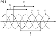
- the voltage determining device 30 can repeatedly detect the respective phase voltage U1, U2, U3 during a respective detection period T1, T2, T3 and, separated for each phase, the respective mean value of the detected phase voltages U1, U2, Form U3.
- the detection periods T1, T2, T3 each form a whole number of periods for the respective phase voltage U1, U2, U3.
- the acquisition periods T1, T2, T3 for the phase voltages U1, U2, U3 can be chosen arbitrarily. In particular, they can be determined uniformly.
- the controller 12 determines the detection periods T1, T2, T3 as shown in FIG FIG. 11 but individually and independently.
- the control device 12 can determine the respective detection period T1, T2, T3 such that the respectively first detection of a respective phase voltage U1, U2, U3 takes place immediately after the zero crossing of the respective phase voltage U1, U2, U3.
- the zero crossing is usually related to the real or virtual potential of the neutral point 29.
- the control device 12 In the case of determining the DC voltage components G1, G2, G3, the control device 12 according to FIG. 10 for each of the phases in each case an offset controller 34.
- the respective offset controller 34 receives the respective DC voltage component G1, G2, G3. Based on the respective DC voltage component G1, G2, G3, it determines a respective second correction value k21, k22, k23 for the respective desired filter current IC1 *, IC2 *, IC3 *.
- the respective second correction value k21, k22, k23 and the respective respective reference filter current IC1 *, IC2 *, IC3 * corrected by the first correction value k11, k12, k13 are supplied to a respective second correction block 35, which supplies the respective desired correction current.
- the correction can be made in particular by adding the respective Target filter current IC1 *, IC2 *, IC3 * and the respective second correction value k21, k22, k23 be realized.
- the offset controllers 34 are - analogous to the voltage regulators 25 and the amplitude regulators 32 - controllers which have an integral component or show an integrating behavior.
- the offset controller 34 may be formed as (pure) integral controller.
- the dynamics of the offset controller 34, the amplitude controller 32 and the setpoint generator 25 should be coordinated.
- the setpoint generator 25 should have the greatest dynamics.
- the dynamics of the offset controller 34 and the amplitude controller 32 should therefore be less than that of the setpoint generator 25.
- the offset controller 34 has a dynamic which is greater than the dynamics of the amplitude controller 32.
- the offset controller 34 should react three to five times as fast to a fault as the amplitude controller 32. Compared to the setpoint generator 25 but their dynamics should be about 1/3 to 2/3.
- the present invention has many advantages. Due to the direct current control, which works both in normal operation and in short-circuit operation, no switching from a voltage regulation to a current regulation is required in the event of a short circuit. This can avoid transient disturbances that would otherwise occur. Nevertheless, in particular short-circuit currents can be dynamically provided and limited. It is a simple transition from an off-grid operation to a network parallel operation and vice versa possible. Even at the current limit of the inverter 2, a stable operation is possible. Furthermore, the control device 12 according to the invention can also be used in conjunction with a load 9, which dynamically - for example when switching - although for a certain time an increased power consumption, but then again requires less power. An example of such a load 9 is a larger asynchronous machine.
- phase voltages U1, U2, U3 It can be achieved in normal operation, a high quality in the provision of the phase voltages U1, U2, U3. This applies regardless of whether the load 9 is linear or non-linear and / or whether the load 9 is symmetrical or asymmetrical. Furthermore, the procedure according to the invention is not restricted to a specific coordinate system.
Abstract
Ein Umrichter (2) schaltet für eine Anzahl an Phasen alternierend jeweils ein hohes und ein niedriges Potenzial (U+,U-) über Phaseneinheiten (3) an Phasenleitungen (5) an und speist dadurch in die Phasenleitungen (5) Phasenströme (I1, I2, I3) ein. Die Phasenströme (I1, I2, I3) werden über eine dem Umrichter (2) nachgeordnete Filtereinrichtung (6) geführt, die über an die Phasenleitungen (5) angeschlossene Filterkondensatoren (8) Filterströme (IC1, IC2, IC3) abgreift und die verbleibenden Teile der Phasenströme (I1, I2, I3) einer elektrischen Last (9) als Lastströme (Il1, IL2, IL3) zuführt. Die Steuereinrichtung (12) nimmt die einspeisten Phasenströme (I1, I2, I3) entgegen. Eine Regeleinrichtung (15) der Steuereinrichtung (12) ermittelt die Ansteuersignale (S) für die Phaseneinheiten (3) des Umrichters (2) mittels einer direkten Stromregelung, der als Istwerte ausgangsseitig des Umrichters (2) fließende Ströme (z.B. I1, IC1) und als Sollwerte die zugehörigen Sollströme (z.B. I1*, IC1*) zugeführt werden. Sie ermittelt die Ansteuersignale (S) derart dass ein Spannungsverlauf hinter der Filtereinrichtung (6) eine vorbestimmte Amplitude (U0) aufweist, wenn und solange die einspeisten Phasenströme einen Mindestabstand von einem vorbestimmten Maximalwert (MAX) aufweisen. Anderenfalls greift die Steuereinrichtung (12) durch eine weitere Einrichtung (15b, 22) in die Ansteuerung der Phaseneinheiten (3) ein, so dass die Phasenströme (I1, I2, I3) auf den Maximalwert (MAX) begrenzt werden, bis der Spannungsverlauf hinter der Filtereinrichtung (6) wieder die vorbestimmte Amplitude (U0) aufweist.A converter (2) switches alternately for a number of phases in each case a high and a low potential (U +, U-) via phase units (3) to phase lines (5) and thereby feeds into the phase lines (5) phase currents (I1, I2 , I3). The phase currents (I1, I2, I3) are conducted via a filter device (6) disposed downstream of the converter (2), which taps filter currents (IC1, IC2, IC3) via filter capacitors (8) connected to the phase lines (5) and the remaining parts the phase currents (I1, I2, I3) an electric load (9) as load currents (Il1, IL2, IL3) supplies. The control device (12) receives the injected phase currents (I1, I2, I3). A control device (15) of the control device (12) determines the control signals (S) for the phase units (3) of the converter (2) by means of a direct current control, the currents flowing as actual values on the output side of the inverter (2) (eg I1, IC1) and as desired values the associated nominal currents (eg I1 *, IC1 *) are supplied. It determines the drive signals (S) such that a voltage curve behind the filter device (6) has a predetermined amplitude (U0) if and as long as the supplied phase currents have a minimum distance from a predetermined maximum value (MAX). Otherwise, the control device (12) by a further device (15b, 22) in the control of the phase units (3), so that the phase currents (I1, I2, I3) are limited to the maximum value (MAX) until the voltage waveform behind the filter device (6) again has the predetermined amplitude (U0).
Description
Die vorliegende Erfindung geht aus von einer Steuereinrichtung für einen Umrichter, wobei der Umrichter für eine Anzahl an Phasen alternierend jeweils ein eingangsseitig des Umrichters bereitgestelltes hohes Potenzial und ein eingangsseitig des Umrichters bereitgestelltes niedriges Potenzial über eine jeweilige Phaseneinheit des Umrichters an je eine Phasenleitung anschaltet und dadurch in die Phasenleitungen Phasenströme einspeist, wobei die Phasenströme über eine dem Umrichter nachgeordnete Filtereinrichtung geführt werden, wobei die Filtereinrichtung über eine Anzahl von an Anschlusspunkten der Phasenleitungen zwischen den Phasenleitungen untereinander angeordnete Filterkondensatoren oder über eine Anzahl von an den Anschlusspunkten an je eine der Phasenleitungen angeschlossene Filterkondensatoren an den Phasenleitungen Filterströme abgreift und die verbleibenden Teile der Phasenströme einer elektrischen Last als Lastströme zuführt,
- wobei die Steuereinrichtung eine Regeleinrichtung aufweist, die Ansteuersignale für die Phaseneinheiten des Umrichters ermittelt und die Phaseneinheiten des Umrichters entsprechend ansteuert,
- wobei die Steuereinrichtung die in die Phasenleitungen einspeisten Phasenströme entgegennimmt.
- wherein the control device has a control device which determines activation signals for the phase units of the converter and correspondingly activates the phase units of the converter,
- wherein the control device receives the phase currents fed into the phase lines.
Die vorliegende Erfindung geht weiterhin aus von einem Steuerprogramm für eine programmierbare Steuereinrichtung für einen Umrichter, wobei das Steuerprogramm Maschinencode umfasst, durch den die Steuereinrichtung derart ausgebildet wird.The present invention is further based on a control program for a programmable controller for an inverter, wherein the control program comprises machine code, by which the control device is formed in such a way.
Die vorliegende Erfindung geht weiterhin aus von einer Umrichtereinheit,
- wobei die Umrichtereinheit einen Umrichter aufweist, der für eine Anzahl an Phasen alternierend jeweils ein eingangsseitig des Umrichters bereitgestelltes hohes Potenzial und ein eingangsseitig des Umrichters bereitgestelltes niedriges Potenzial über eine jeweilige Phaseneinheit des Umrichters an je eine Phasenleitung anschaltet und dadurch in die Phasenleitungen Phasenströme einspeist,
- wobei die Umrichtereinheit eine dem Umrichter nachgeordnete Filtereinrichtung aufweist, über die die Phasenströme geführt werden,
- wobei die Filtereinrichtung über eine Anzahl von an Anschlusspunkten der Phasenleitungen zwischen den Phasenleitungen untereinander angeordnete Filterkondensatoren oder über eine Anzahl von an den Anschlusspunkten an je eine der Phasenleitungen angeschlossene Filterkondensatoren an den Phasenleitungen Filterströme abgreift und die verbleibenden Teile der Phasenströme einer elektrischen Last als Lastströme zuführt,
- wobei die Umrichtereinheit eine Steuereinrichtung der eingangs genannten Art aufweist, welche den Umrichter steuert.
- wherein the converter unit comprises a converter which, for a number of phases, alternately has a high potential provided on the input side of the converter and a low one provided on the input side of the converter Turns on potential via a respective phase unit of the converter to a respective phase line and thereby feeds phase currents into the phase lines,
- wherein the converter unit has a filter device arranged downstream of the converter, via which the phase currents are conducted,
- wherein the filter device picks up filter currents at the phase lines via a number of filter capacitors arranged at connection points of the phase lines between the phase lines or via a number of filter capacitors connected to the connection points on each of the phase lines and supplies the remaining parts of the phase currents to an electrical load as load currents,
- wherein the converter unit has a control device of the type mentioned, which controls the inverter.
Umrichter und die zugehörigen Steuereinrichtungen sind allgemein bekannt. Sie arbeiten meist nach dem Prinzip, dass die Steuereinrichtung anhand von innerhalb oder hinter der Filtereinrichtung auftretenden Phasenspannungen in Verbindung mit Soll-Phasenspannungen die Ansteuersignale für die Phaseneinheiten des Umrichters ermittelt. Die Ansteuersignale können beispielsweise derart ermittelt werden, dass eine pulsweitenmodulierte Ansteuerung der Phaseneinheiten erfolgt. Die entsprechende Vorgehensweise ist Fachleuten allgemein bekannt. Sie erfolgt in der Regel mittels einer sogenannten Raumzeigermodulation. Mit diesen Vorgehensweisen können die der Last zugeführten Phasenspannungen auf wenige Volt genau geregelt werden.Inverter and the associated control devices are well known. They usually operate on the principle that the control device determines the control signals for the phase units of the converter on the basis of phase voltages occurring inside or behind the filter device in conjunction with desired phase voltages. The control signals can be determined, for example, such that a pulse-width-modulated control of the phase units takes place. The appropriate procedure is generally known to experts. It is usually done by means of a so-called space vector modulation. With these procedures, the phase voltages supplied to the load can be controlled to a few volts exactly.
Bei einer Ermittlung von Soll-Phasenspannungen und einer darauf aufbauenden Ermittlung der Ansteuersignale stellen sich die Phasenströme frei ein. Im Ergebnis werden sie durch die Last bestimmt. Dies ist problemlos, solange die sich einstellenden Phasenströme unterhalb eines maximal zulässigen Maximalwertes liegen. Wird dieser Maximalwert jedoch erreicht oder überschritten, muss der Umrichter im Stand der Technik sehr schnell abgeschaltet werden, um ihn vor Zerstörung zu schützen. Bei den Umrichtern des Standes der Technik werden daher weiterhin die ausgangsseitig des Umrichters fließenden Phasenströme erfasst und von der Steuereinrichtung entgegengenommen. Übersteigen die Phasenströme einen vorbestimmten Maximalwert - beispielsweise weil in der Last ein Kurzschluss aufgetreten ist - wird der Umrichter abgeschaltet.In a determination of desired phase voltages and a subsequent determination of the drive signals, the phase currents set free. As a result, they are determined by the load. This is problem-free, as long as the phase currents that occur are below a maximum permissible maximum value. However, if this maximum value is reached or exceeded, the inverter in the prior art must be very be shut down quickly to protect it from destruction. In the converters of the prior art, therefore, the phase currents flowing on the output side of the converter are furthermore detected and accepted by the control device. If the phase currents exceed a predetermined maximum value-for example because a short circuit has occurred in the load-the converter is switched off.
Die Vorgehensweise des Standes der Technik funktioniert sehr gut, wenn mittels des Umrichters nur eine einzelne, singuläre Last mit elektrischer Energie versorgt wird, beispielsweise ein einzelner Antrieb. In manchen Fällen soll der Umrichter jedoch ein sogenanntes Inselnetz mit elektrischer Energie versorgen, d.h. alle Verbraucher, die innerhalb des entsprechenden Inselnetzes angeordnet sind. Tritt in einem derartigen Fall in einem der Verbraucher ein Kurzschluss und damit ein erhöhter Stromfluss auf, ist es prinzipiell zwar weiterhin möglich, in diesem Fall den Umrichter abzuschalten. Dies führt jedoch dazu, dass nicht nur der defekte Verbraucher abgeschaltet wird, sondern alle Verbraucher des Inselnetzes.The approach of the prior art works very well, if by means of the inverter only a single, singular load is supplied with electrical energy, for example a single drive. In some cases, however, the inverter is intended to supply a so-called off-grid with electrical energy, i. all consumers located within the corresponding island grid. If, in such a case, a short circuit occurs in one of the consumers and thus an increased current flow, it is still possible in principle to switch off the converter in this case. However, this means that not only the defective consumer is switched off, but all consumers of the island grid.
Um ein Abschalten des Umrichters für alle Verbraucher zu vermeiden, werden daher den einzelnen Verbrauchern oder Gruppen von Verbrauchern Abschaltelemente wie beispielsweise Sicherungen oder Leistungsschalter vorgeordnet, die im Kurzschlussfall den Stromfluss vom Umrichter zu dem jeweiligen Verbraucher bzw. zu der jeweiligen Gruppe von Verbrauchern unterbrechen. Der Umrichter selbst wird hingegen nicht abgeschaltet. Der verbleibende Teil des Inselnetzes wird dadurch vom Umrichter weiterhin mit elektrischer Energie versorgt.To avoid switching off the inverter for all consumers, the individual consumers or groups of consumers shutdown elements such as fuses or circuit breakers are preceded, interrupt the current flow from the inverter to the respective consumer or to the respective group of consumers in the event of a short circuit. The inverter itself is not switched off. The remaining part of the island grid is thus still supplied by the inverter with electrical energy.
Problematisch bei dieser Gestaltung ist, dass die Abschaltelemente üblicherweise Reaktionszeiten im Sekundenbereich (und teilweise sogar darüber) aufweisen. Ein Umrichter ist hingegen nur für wenige Mikrosekunden überlastfähig. Es muss daher durch geeignete Maßnahmen gewährleistet werden, dass die von den Phaseneinheiten in die Phasenleitungen eingespeisten Phasenströme den vom Umrichter maximal verkraftbaren Strom nicht übersteigen.The problem with this design is that the shutdown usually have response times in the second range (and sometimes even above). On the other hand, a converter can only be overloaded for a few microseconds. It must therefore be ensured by suitable measures that the phase currents fed by the phase units into the phase lines Do not exceed the maximum current that can be consumed by the inverter.
Eine denkbare Lösung besteht darin, den Umrichter entsprechend auszulegen, so dass er auch die hohen Kurzschlussströme verkraftet. Dies würde jedoch dazu führen, dass der Umrichter für den Normalbetrieb, in dem kein Kurzschluss auftritt, weit überdimensioniert ist. Diese Lösung ist somit nicht wirtschaftlich. In der Praxis müssen daher andere Wege gefunden werden, um den Betrieb des Umrichters auch bei einem Kurzschluss in einem der angeschlossenen Verbraucher aufrechterhalten zu können. Insbesondere müssen somit die in den Phasenleitungen eingespeisten Phasenströme auf geeignete Weise begrenzt werden. Die Phasenströme müssen jedoch so hoch liegen, dass dasjenige Abschaltelement, welches dem defekten Verbraucher vorgeordnet ist, zuverlässig abschaltet. Der Umrichter muss daher mit einer reduzierten Ausgangsspannung weiter betrieben werden. Diese reduzierte Ausgangsspannung muss derart bestimmt sein, dass der Umrichter einerseits die entsprechend hohen Phasenströme liefert, so dass das Abschaltelement auslöst, der Umrichter andererseits aber durch die hohen Phasenströme nicht beschädigt wird.One conceivable solution is to design the converter accordingly so that it can handle the high short-circuit currents as well. However, this would mean that the converter for normal operation, in which no short circuit occurs, is far over-dimensioned. This solution is therefore not economical. In practice, therefore, other ways must be found to maintain the operation of the inverter even with a short circuit in one of the connected consumers can. In particular, therefore, the phase currents fed into the phase lines must be suitably limited. However, the phase currents must be so high that the switch-off element, which is upstream of the defective consumer, reliably switches off. The inverter must therefore continue to operate with a reduced output voltage. This reduced output voltage must be determined in such a way that the converter on the one hand supplies the correspondingly high phase currents, so that the turn-off element triggers, the other hand, the converter is not damaged by the high phase currents.
Die Aufgabe der vorliegenden Erfindung besteht darin, Möglichkeiten zu schaffen, mittels derer auf einfache und effiziente Weise sowohl ein Normalbetrieb des Umrichters (d.h. die Phasenspannungen liegen mit geringfügigen Abweichungen bei ihren Sollwerten und die eingespeisten Phasenströme liegen unterhalb des Maximalwertes) als auch ein Kurzschlussbetrieb (d.h. die Phasenspannungen werden auf Werte unterhalb ihrer Sollwerte begrenzt, damit die in die Phasenleitungen eingespeisten Phasenströme nicht über den Maximalwert ansteigen) realisiert werden kann. Insbesondere soll ein einfaches und störungsfreies Umschalten zwischen Normalbetrieb und Kurzschlussbetrieb möglich sein.The object of the present invention is to provide means by which in a simple and efficient manner, both a normal operation of the inverter (ie the phase voltages lie with minor deviations in their setpoints and the injected phase currents are below the maximum value) as well as a short-circuit operation (ie the phase voltages are limited to values below their setpoints, so that the phase currents fed into the phase lines do not rise above the maximum value) can be realized. In particular, a simple and trouble-free switching between normal operation and short-circuit operation should be possible.
Die Aufgabe wird durch eine Steuereinrichtung mit den Merkmalen des Anspruchs 1 gelöst. Vorteilhafte Ausgestaltungen der Steuereinrichtung sind Gegenstand der abhängigen Ansprüche 2 bis 15.The object is achieved by a control device with the features of
Erfindungsgemäß wird eine Steuereinrichtung der eingangs genannten Art dadurch ausgestaltet,
- dass die Regeleinrichtung die Ansteuersignale für die Phaseneinheiten des Umrichters mittels einer direkten Stromregelung ermittelt, der als Istwerte ausgangsseitig des Umrichters fließende Ströme und als Sollwerte die zugehörigen Sollströme zugeführt werden,
- dass die Regeleinrichtung die Ansteuersignale derart ermittelt, dass ein durch das Ansteuern der Phaseneinheiten bewirkter Spannungsverlauf hinter der Filtereinrichtung eine vorbestimmte Amplitude aufweist, wenn und solange die Beträge der in die Phasenleitungen einspeisten Phasenströme einen Mindestabstand von einem vorbestimmten Maximalwert aufweisen, und
- dass die Steuereinrichtung durch eine weitere Einrichtung derart in die Ansteuerung der Phaseneinheiten eingreift, dass die Beträge der in die Phasenleitungen einspeisten Phasenströme auf den Maximalwert begrenzt werden, bis der durch das Ansteuern der Phaseneinheiten bewirkte Spannungsverlauf hinter der Filtereinrichtung wieder die vorbestimmte Amplitude aufweist.
- the control device determines the control signals for the phase units of the converter by means of a direct current control, to which the currents flowing as actual values on the output side of the converter and to the associated desired currents as desired values,
- that the control device determines the control signals in such a way that a voltage curve caused by the activation of the phase units has a predetermined amplitude behind the filter device if and as long as the amounts of the phase currents fed into the phase lines have a minimum distance from a predetermined maximum value, and
- in that the control device intervenes in the control of the phase units by means of a further device in such a way that the amounts of the phase currents fed into the phase lines are limited to the maximum value until the voltage curve effected by the activation of the phase units has the predetermined amplitude behind the filter device again.
Es werden also Ströme direkt geregelt. Diese Art der Regelung ist hochdynamisch realisierbar. Die direkte Stromregelung kann sowohl im Kurzschlussbetrieb auch im Normalbetrieb wirken. Es muss lediglich im Kurzschlussbetrieb der in der jeweiligen Phasenleitung fließende Phasenstrom auf seinen Maximalwert begrenzt werden.This means that currents are regulated directly. This type of control is highly dynamic realizable. The direct current control can also work in short-circuit operation in normal operation. It must be limited to its maximum value only in short-circuit operation of the current flowing in the respective phase line phase current.
Die direkte Stromregelung kann beispielsweise nach Art eines Zweipunktreglers arbeiten: Es wird für die zu regelnden Ströme jeweils ein Intervall um den jeweiligen Sollstrom definiert, innerhalb dessen der jeweilige Iststrom liegen soll. Erreicht bzw. unterschreitet der jeweilige Iststrom die obere oder untere Grenze des Intervalls, wird jeweils die Ansteuerung des Umrichters entsprechend geändert. Insbesondere kann beispielsweise durch die jeweilige Phaseneinheit das an die jeweilige Phasenleitung angeschaltete eingangsseitige Potenzial gewechselt werden. Es sind aber auch andere Arten der Regelung denkbar. Insbesondere ist es auch umgekehrt möglich, bei den anderen Phasenleitungen an das an diese Phasenleitungen angeschaltete Potenzial zu wechseln. Denn es kommt darauf an, die Potenzialdifferenz (= die Spannung) zwischen den einzelnen Phasen zu reduzieren. Dafür kann entweder das Potenzial in einer Phasenleitung an die Potenziale in den anderen Phasenleitungen angepasst werden oder aber es können die Potenziale in den anderen Phasenleitungen an das Potenzial in der einen Phasenleitung angepasst werden. Ein bekanntes und auch vorliegend einsetzbares Verfahren zur Stromregelung ist beispielsweise das sogenannte SDHC-Verfahren. SDHC steht für Switched Diamond Hysteresis Control.The direct current control can operate, for example, in the manner of a two-point controller: It is defined for the currents to be regulated in each case an interval around the respective target current, within which the respective actual current should be. If the respective actual current reaches or falls below the upper or lower limit of the interval, the drive of the inverter is triggered in each case changed accordingly. In particular, the input-side potential connected to the respective phase line can, for example, be changed by the respective phase unit. But there are also other types of control conceivable. In particular, conversely, it is also possible to change the potential applied to these phase lines in the case of the other phase lines. Because it is important to reduce the potential difference (= the voltage) between the individual phases. Either the potential in one phase line can be adapted to the potentials in the other phase lines, or the potentials in the other phase lines can be adapted to the potential in the one phase line. A known and also applicable current control method is, for example, the so-called SDHC method. SDHC stands for Switched Diamond Hysteresis Control.
Die Filtereinrichtung umfasst - zusätzlich zu den Filterkondensatoren - vorzugsweise vor und hinter den Anschlusspunkten je eine in der jeweiligen Phasenleitung angeordnete Induktivität. Es sind aber auch andere Ausgestaltungen der Filtereinrichtung möglich.The filter device comprises - in addition to the filter capacitors - preferably in front of and behind the connection points each arranged in the respective phase line inductance. But there are also other embodiments of the filter device possible.
In Einzelfällen ist es möglich, dass der Umrichter nur ein einphasiges Wechselspannungssystem betreibt. In diesem Fall weist der Umrichter zwei Phasenleitungen auf. Im Regelfall betreibt der Umrichter jedoch ein Drehstromsystem mit mindestens drei Phasen, meist exakt drei Phasen. In diesem Fall können die Filterkondensatoren entweder nach Art einer Dreieckschaltung an je zwei Phasenleitungen angeschlossen sein oder nach Art einer Sternschaltung einen gemeinsamen Sternpunkt aufweisen. Im Falle einer Sternschaltung kann das Potenzial des Sternpunkts alternativ relativ zu den eingangsseitigen Potenzialen fest definiert sein oder bezüglich dieser Potenziale schwebend und variabel sein.In individual cases, it is possible that the inverter operates only a single-phase AC voltage system. In this case, the inverter has two phase lines. As a rule, however, the inverter operates a three-phase system with at least three phases, usually exactly three phases. In this case, the filter capacitors can either be connected to two phase lines in the manner of a delta connection or have a common star point in the manner of a star connection. In the case of a star connection, the potential of the star point may alternatively be fixed relative to the input-side potentials or be floating and variable with respect to these potentials.
Durch die direkte Stromregelung auch im Normalbetrieb ist es weiterhin nicht erforderlich, von einer pulsweitenmodulierten Spannungsregelung, die im Normalbetrieb ausreichend ist, auf eine direkte Stromregelung umzuschalten, die im Kurzschlussbetrieb erforderlich ist. Das Regelverfahren kann vielmehr einheitlich für Normalbetrieb und Kurzschlussbetrieb beibehalten werden. Es ist lediglich erforderlich, die Soll-Phasenströme entsprechend zu begrenzen.Due to the direct current control even in normal operation, it is still not required by a pulse width modulated Voltage control, which is sufficient in normal operation, to switch to a direct current control, which is required in short-circuit operation. The control method can rather be maintained uniformly for normal operation and short-circuit operation. It is only necessary to limit the desired phase currents accordingly.
Es ist möglich,
- dass die weitere Einrichtung als Umschalteinrichtung ausgebildet ist,
- dass die Umschalteinrichtung der Regeleinrichtung in einem Normalbetrieb als Istwerte die Filterströme und als Sollwerte von einem Sollwertgeber ermittelte Soll-Filterströme zuführt, wenn und solange die Beträge der in die Phasenleitungen einspeisten Phasenströme den Mindestabstand von dem vorbestimmten Maximalwert aufweisen,
- dass die Umschalteinrichtung vom Normalbetrieb in einen Kurzschlussbetrieb übergeht, in dem die Umschalteinrichtung der Regeleinrichtung als Istwerte die Phasenströme und als Sollwert den Maximalwert oder das Inverse des Maximalwerts zuführt, wenn und sobald die Beträge der Phasenströme den Mindestabstand vom Maximalwert unterschreiten, und
- dass die Umschalteinrichtung vom Kurzschlussbetrieb wieder in den Normalbetrieb übergeht, wenn und sobald der durch das Ansteuern der Phaseneinheiten bewirkte Spannungsverlauf hinter der Filtereinrichtung wieder die vorbestimmte Amplitude aufweist.
- that the further device is designed as a switching device,
- that the switching means of the control device in a normal operation as actual values, the filter currents and as setpoints from a setpoint generator determined desired filter currents supplies, if and as long as the amounts of phase currents fed into the phase currents have the minimum distance from the predetermined maximum value,
- the switching device changes from normal operation to a short-circuit operation, in which the switching device supplies the phase currents as actual values and the maximum value or the inverse of the maximum value as setpoint value, if and as soon as the amounts of the phase currents fall below the minimum distance from the maximum value, and
- the switching device switches from short-circuit operation back to normal operation when and as soon as the voltage curve caused by the activation of the phase units has the predetermined amplitude behind the filter device again.
Durch diese Art der Regelung ist eine gute Spannungsregelung im Normalbetrieb besonders einfach zu implementieren. Diese Vorgehensweise beruht auf der Überlegung, dass im Normalbetrieb der zeitliche Verlauf der Phasenspannungen bekannt ist und damit auch der zeitliche Verlauf der Filterströme bekannt ist. Somit können die zugehörigen zeitlichen Verläufe der Soll-Filterströme vorgegeben werden und die Filterströme auf ihre Sollwerte geregelt werden. Dadurch stellen sich die Phasenspannungen entsprechend den Sollverläufen ein. Durch das Umschalten auf Regelung der Phasenströme im Kurzschlussbetrieb wird der Umrichter jedoch vor Überlastung geschützt.By this type of control, a good voltage regulation in normal operation is particularly easy to implement. This procedure is based on the consideration that in normal operation, the time profile of the phase voltages is known and thus the time profile of the filter currents is known. Thus, the associated time profiles of the desired filter currents can be specified and the filter currents can be regulated to their desired values. As a result, the phase voltages set in accordance with the target curves. By switching to However, the control of the phase currents in short-circuit operation protects the inverter against overload.
Im einfachsten Fall nimmt die Steuereinrichtung die Filterströme selbst als Messgrößen entgegen. Eine direkte Strommessung weist jedoch den Nachteil auf, dass die entsprechende Strommesseinrichtung relativ kostenintensiv ist. Vorzugsweise ermittelt die Steuereinrichtung die Filterströme daher anhand erfasster und von der Steuereinrichtung entgegengenommener Messgrößen. Als weitere Messgrößen kommen insbesondere Phasenspannungen der Phasenleitungen in Frage, die innerhalb oder hinter der Filtereinrichtung gemessen werden. Wenn die Phasenspannungen innerhalb der Filtereinrichtung gemessen werden, können die Filterströme - zumindest in manchen Fällen - direkt anhand der erfassten Phasenspannungen ermittelt werden. Wenn die Phasenspannungen hinter der Filtereinrichtung gemessen werden, können die Filterströme anhand der erfassten Phasenspannungen und der ausgangsseitig des Umrichters erfassten Phasenströme modellgestützt ermittelt werden.In the simplest case, the control device accepts the filter streams themselves as measured variables. However, a direct current measurement has the disadvantage that the corresponding current measuring device is relatively expensive. The control device therefore preferably determines the filter flows on the basis of detected measured variables and received by the control device. In particular, phase voltages of the phase lines which are measured inside or behind the filter device can be considered as further measured variables. When the phase voltages within the filter device are measured, the filter currents can be determined, at least in some cases, directly from the detected phase voltages. When the phase voltages downstream of the filter device are measured, the filter currents can be modeled based on the detected phase voltages and the phase currents detected on the output side of the inverter.
Alternativ zu einem Umschalten zwischen einer Regelung der Filterströme im Normalbetrieb und einer Regelung der Phasenströme im Kurzschlussbetrieb ist es möglich, dass der Regeleinrichtung stets die Phasenströme zugeführt werden. In diesem Fall ist die Steuereinrichtung derart ausgestaltet, dass
- die Steuereinrichtung anhand der Phasenströme und weiterer ausgangsseitig des Umrichters erfasster Messgrößen für die Phasenleitungen die der Last zugeführten Lastströme ermittelt,
- die Steuereinrichtung einen Sollwertgeber aufweist, der für die Phasenleitungen Soll-Filterströme ermittelt,
- die Steuereinrichtung eine Additionseinrichtung aufweist, der die von der Stromermittlungseinrichtung ermittelten Lastströme und die Soll-Filterströme zugeführt werden und die anhand der Lastströme und der Soll-Filterströme vom Umrichter bereitzustellende vorläufige Soll-Phasenströme ermittelt, und
- eine weitere Einrichtung als Begrenzungseinrichtung ausgebildet ist, der die von der Additionseinrichtung ermittelten vorläufigen Soll-Phasenströme zugeführt werden und die den Betrag der vorläufigen Soll-Phasenströme auf den Maximalwert begrenzt und die entsprechend begrenzten Soll-Phasenströme der Regeleinrichtung als Sollwerte zuführt.
- the control device determines the load currents supplied to the load on the basis of the phase currents and further measured variables for the phase lines detected on the output side of the converter;
- the control device has a nominal value transmitter which determines desired filter currents for the phase lines,
- the control device has an addition device to which the load currents determined by the current detection device and the desired filter currents are supplied and which determines the provisional desired phase currents to be provided by the converter on the basis of the load currents and the desired filter currents, and
- a further device is designed as a limiting device to which the provisional desired phase currents determined by the addition device are supplied and which the Limits the amount of preliminary target phase currents to the maximum value and supplies the correspondingly limited desired phase currents to the control device as setpoint values.
Da in diesem Fall die Lastströme mittels der Stromermittlungseinrichtung mit hoher Dynamik ermittelt werden und die Soll-Filterströme auf den Normalbetrieb bezogen sind, muss lediglich noch die Begrenzung der vorläufigen Soll-Phasenströme vorgenommen werden, um einen zuverlässigen Betrieb des Umrichters zu gewährleisten. Ein Umschalten ist nicht mehr erforderlich.Since in this case the load currents are determined by means of the current detection device with high dynamics and the target filter currents are related to the normal operation, only the limitation of the provisional nominal phase currents must be made to ensure reliable operation of the inverter. Switching is no longer necessary.
Auch diese Betriebsart beruht auf der Überlegung, dass im Normalbetrieb der zeitliche Verlauf der Phasenspannungen bekannt ist und damit auch der zeitliche Verlauf der Filterströme bekannt ist. Durch Vorgabe der zugehörigen zeitlichen Verläufe der Soll-Filterströme in Kombination mit den ermittelten Lastströmen können somit die Sollwerte für die Stromregelung bereitgestellt werden.This operating mode is also based on the consideration that in normal operation, the time profile of the phase voltages is known and thus the time course of the filter currents is known. By specifying the associated time profiles of the desired filter currents in combination with the determined load currents, the setpoint values for the current control can thus be provided.
Im einfachsten Fall nimmt die Steuereinrichtung als weitere Messgrößen direkt die Filterströme entgegen. Eine direkte Strommessung weist jedoch den Nachteil auf, dass die entsprechende Strommesseinrichtung relativ kostenintensiv ist. Vorzugsweise nimmt die Steuereinrichtung daher als weitere Messgrößen Phasenspannungen der Phasenleitungen entgegen, die innerhalb oder hinter der Filtereinrichtung erfasst werden. Wenn die Phasenspannungen innerhalb der Filtereinrichtung erfasst werden, kann die Stromermittlungseinrichtung die Filterströme - zumindest in manchen Fällen - direkt anhand der erfassten Phasenspannungen ermitteln. Aus den Filterströmen können sodann in Verbindung mit den Phasenströmen die Lastströme ermittelt werden. Wenn die Phasenspannungen hinter der Filtereinrichtung erfasst werden, werden die Lastströme anhand der erfassten Phasenspannungen und der ausgangsseitig des Umrichters erfassten Phasenströme modellgestützt ermittelt.In the simplest case, the control device directly accepts the filter streams as further measured variables. However, a direct current measurement has the disadvantage that the corresponding current measuring device is relatively expensive. The control device therefore preferably receives phase voltages of the phase lines, which are detected within or behind the filter device, as further measured variables. If the phase voltages are detected within the filter device, the current determination device can determine the filter currents-at least in some cases-directly on the basis of the detected phase voltages. The load currents can then be determined from the filter currents in conjunction with the phase currents. When the phase voltages are sensed downstream of the filter device, the load currents are modeled based on the detected phase voltages and the phase currents detected on the output side of the drive.
In einer bevorzugten Ausgestaltung weist die Steuereinrichtung eine Recheneinrichtung und eine Extrapolationseinrichtung auf. Die Recheneinrichtung ermittelt die Filterströme oder die der Last zugeführten Lastströme. Die Ermittlung erfolgt für einen Zeitpunkt, zu dem die Messgrößen, anhand derer die Filterströme oder die Lastströme ermittelt werden, erfasst werden. Die Recheneinrichtung führt die von ihr ermittelten Filterströme oder Lastströme der Extrapolationseinrichtung zu. Die Extrapolationseinrichtung modifiziert die ihr zugeführten Filterströme oder Lastströme derart, dass sie in Bezug auf eine Nennfrequenz der Phasenspannungen um eine Extrapolationszeit extrapoliert sind. Sodann führt die Extrapolationseinrichtung die von ihr modifizierten Filterströme der Umschalteinrichtung oder Lastströme der Additionseinrichtung zu. Die Extrapolationszeit ist geeignet bestimmt. Sie ist insbesondere derart bestimmt, dass die Modifikationen - bezogen auf eine vorab bekannte Nennfrequenz der Phasenspannungen - die entsprechende zeitliche Veränderung der Filterströme widerspiegeln.In a preferred embodiment, the control device has a computing device and an extrapolation device. The computing device determines the filter currents or the load currents supplied to the load. The determination is made for a point in time at which the measured variables, by means of which the filter currents or the load currents are determined, are detected. The computing device supplies the filter currents or load currents determined by it to the extrapolation device. The extrapolator modifies the filter currents or load currents supplied to it in such a way that they are extrapolated with respect to a nominal frequency of the phase voltages by an extrapolation time. The extrapolation device then supplies the filter streams modified by it to the switching device or load currents of the addition device. The extrapolation time is suitably determined. In particular, it is determined in such a way that the modifications - based on a previously known nominal frequency of the phase voltages - reflect the corresponding temporal change of the filter currents.
Alternativ ist es möglich, dass die Reihenfolge von Ermittlung mittels der Recheneinrichtung und Extrapolation mittels der Extrapolationseinrichtung vertauscht sind. In diesem Fall modifiziert die Extrapolationseinrichtung die Messgrößen, anhand derer die Filterströme oder die der Last zugeführten Lastströme ermittelt werden, derart, dass sie gegenüber einem Zeitpunkt, zu dem die Messgrößen erfasst werden, in Bezug auf eine Nennfrequenz der Phasenspannungen um die Extrapolationszeit extrapoliert sind. Sie führt die von ihr modifizierten Messgrößen der Recheneinrichtung zu. Die Recheneinrichtung ermittelt in diesem Fall anhand der ihr zugeführten modifizierten Messgrößen die Filterströme oder die Lastströme und führt die Filterströme der Umschalteinrichtung oder die Lastströme der Additionseinrichtung zu.Alternatively, it is possible that the order of detection by means of the computing means and extrapolation by means of the extrapolation means are reversed. In this case, the extrapolation means modifies the measured quantities by means of which the filter currents or the load currents supplied to the load are determined in such a way that they are extrapolated with respect to a nominal frequency of the phase voltages by the extrapolation time compared with a time at which the measured variables are detected. It supplies the metrics it modifies to the computing device. In this case, the computing device determines the filter currents or the load currents on the basis of the modified measured variables supplied to it and supplies the filter currents to the switching device or the load currents to the addition device.
Vorzugsweise nimmt die Steuereinrichtung innerhalb oder hinter der Filtereinrichtung erfasste Phasenspannungen der Phasenleitungen entgegen. In diesem Fall sind die Sollwertgeber für die Phasen vorzugsweise als Spannungsregler ausgebildet, dem die erfassten Phasenspannungen und Soll-Phasenspannungen zugeführt werden und der anhand der erfassten Phasenspannungen und der Soll-Phasenspannungen die Soll-Filterströme ermittelt. Dadurch kann auf einfache und zuverlässige Weise die Stabilität der bewirkten Regelung gewährleistet werden.The control device preferably accepts detected phase voltages of the phase lines within or behind the filter device. In this case, the setpoint generator for the phases are preferably designed as a voltage regulator to which the detected phase voltages and target phase voltages are supplied and determines the reference filter currents based on the detected phase voltages and the desired phase voltages. As a result, the stability of the effected control can be ensured in a simple and reliable manner.
Die Sollwertgeber sind vorzugsweise Regler mit Integralanteil, insbesondere PI-Regler. Ihre Dynamik ist oftmals relativ gering. In der Regel benötigen die Sollwertgeber zur Ausregelung einer Störung 2 bis 4 Perioden, insbesondere ca. 3 Perioden. Die Perioden sind auf eine Nennfrequenz bezogen, mit der die Phasenspannungen oszillieren sollen.The setpoint generators are preferably controllers with an integral component, in particular a PI controller. Their dynamics are often relatively low. As a rule, the setpoint value transmitters require 2 to 4 periods, in particular approx. 3 periods, to compensate for a fault. The periods are related to a nominal frequency with which the phase voltages are to oscillate.
Vorzugsweise weist die Steuereinrichtung Vorsteuereinrichtungen auf, denen die Soll-Phasenspannungen zugeführt werden und die anhand der Soll-Phasenspannungen Vorsteuerwerte für die von den Sollwertgebern ermittelten Soll-Filterströme ermitteln. In diesem Fall können die Vorsteuerwerte auf die von den Sollwertgebern ermittelten Soll-Filterströme aufgeschaltet werden. Dadurch kann die Dynamik der Führungsgrößenermittlung deutlich verbessert werden, oftmals um 50 % und mehr.The control device preferably has pilot control devices, to which the desired phase voltages are supplied, and which determine precontrol values for the desired filter currents determined by the setpoint generators on the basis of the desired phase voltages. In this case, the pilot control values can be switched to the setpoint filter currents determined by the setpoint generators. As a result, the dynamics of the reference variable determination can be significantly improved, often by 50% or more.
Wie bereits erwähnt, betreibt der Umrichter in der Regel ein Drehstromsystem. Die Anzahl an Phasen beträgt daher mindestens drei. In diesem Fall weist die Steuereinrichtung vorzugsweise eine Spannungsermittlungseinrichtung auf, die die innerhalb oder hinter der Filtereinrichtung erfassten Phasenspannungen der Phasenleitungen entgegennimmt und für die Phasenspannungen jeweils eine auf einen Sternpunkt bezogene Amplitude ermittelt. Weiterhin weist die Steuereinrichtung für die Phasen in diesem Fall jeweils einen Amplitudenregler auf, dem als Istwert die jeweilige Amplitude und als Sollwert der Mittelwert der Amplituden zugeführt werden und der anhand seines jeweiligen Istwerts und seines jeweiligen Sollwerts einen jeweiligen ersten Korrekturwert für den jeweiligen Soll-Filterstrom ermittelt und den jeweiligen Soll-Filterstrom um den jeweiligen ersten Korrekturwert korrigiert. Durch diese Ausgestaltung können die Amplituden der Phasenspannungen aneinander angeglichen werden.As already mentioned, the inverter usually operates a three-phase system. The number of phases is therefore at least three. In this case, the control device preferably has a voltage determination device, which receives the phase voltages of the phase lines detected within or behind the filter device and in each case determines an amplitude related to a star point for the phase voltages. In addition, the control device for the phases in this case each have an amplitude controller to which the respective amplitude is supplied as the actual value and the mean value of the amplitudes as desired value and the respective first correction value for the respective desired filter current based on its respective actual value and its respective setpoint determined and the respective target filter current corrected by the respective first correction value. With this configuration, the amplitudes of the phase voltages can be matched to each other.
Die Ermittlung der auf den Sternpunkt bezogenen Amplituden ist Fachleuten allgemein bekannt. Sie ist insbesondere auch dann durchführbar, wenn (im Falle einer Dreieckschaltung der Filterkondensatoren) der Sternpunkt nicht vorhanden ist oder aber der Sternpunkt zwar vorhanden ist, aber nicht auf die eingangsseitigen Potenziale bezogen ist. Die Amplitudenregler sind in der Regel Regler mit Integralanteil, insbesondere Integralregler.The determination of the star point related amplitudes is well known to those skilled in the art. In particular, it can also be carried out if (in the case of a delta connection of the filter capacitors) the neutral point is absent or the neutral point is present, but is not related to the input-side potentials. The amplitude controllers are usually controllers with integral component, in particular integral controller.
Vorzugsweise ermittelt die Spannungsermittlungseinrichtung für die Phasenspannungen auch jeweils einen auf den Sternpunkt bezogenen jeweiligen Gleichspannungsanteil. In diesem Fall weist die Steuereinrichtung für die Phasen jeweils einen Offsetregler auf, der den jeweiligen Gleichspannungsanteil entgegennimmt und der anhand des jeweiligen Gleichspannungsanteils einen jeweiligen zweiten Korrekturwert für den jeweiligen Soll-Filterstrom ermittelt und den jeweiligen Soll-Filterstrom um den ermittelten jeweiligen zweiten Korrekturwert korrigiert. Dadurch kann erreicht werden, dass die Phasenspannungen offsetfrei eingestellt werden.The voltage determination device for the phase voltages also preferably determines a respective DC voltage component related to the neutral point. In this case, the control device for the phases in each case an offset controller, which receives the respective DC component and the determined based on the respective DC component a respective second correction value for the respective desired filter current and corrects the respective desired filter current to the determined respective second correction value. This can be achieved that the phase voltages are set offset-free.
Die Offsetregler sind in der Regel Regler mit Integralanteil, insbesondere Integralregler.The offset controllers are generally controllers with an integral component, in particular integral controllers.
Zur Ermittlung der Gleichspannungsanteile für die Phasenspannungen nimmt die Spannungsermittlungseinrichtung während eines jeweiligen Erfassungszeitraums jeweils eine Mehrzahl von erfassten Phasenspannungen entgegen und ermittelt den jeweiligen Gleichspannungsanteil als deren jeweiligen Mittelwert. Vorzugsweise bestimmt die Steuereinrichtung den jeweiligen Erfassungszeitraum für die Phasen individuell und unabhängig von den Erfassungszeiträumen für die anderen Phasen. Insbesondere kann die Steuereinrichtung den jeweiligen Erfassungszeitraum mit dem jeweiligen Nulldurchgang der jeweiligen Phasenspannung synchronisieren. Durch diese Vorgehensweise können die Gleichspannungsanteile besonders genau ermittelt werden.In order to determine the DC voltage components for the phase voltages, the voltage determination device accepts a plurality of detected phase voltages during a respective detection period and determines the respective DC voltage component as its respective mean value. Preferably, the control means determines the respective detection period for the phases individually and independently of the detection periods for the other phases. In particular, the control device can synchronize the respective detection period with the respective zero crossing of the respective phase voltage. By this procedure, the DC components can be determined very accurately.
Die Dynamik der verschiedenen Regler ist vorzugsweise derart aufeinander abgestimmt, dass die Offsetregler eine Dynamik aufweisen, die größer als die Dynamik der Amplitudenregler ist. Ein typischer Faktor in der Dynamik liegt in der Regel zwischen 3 und 5. Die Offsetregler weisen jedoch vorzugsweise eine Dynamik auf, die geringer als die Dynamik der Sollwertgeber ist. Ein typischer Faktor in der Dynamik liegt in der Regel zwischen 1/3 und 2/3.The dynamics of the various controllers are preferably matched to one another in such a way that the offset controllers have a dynamic which is greater than the dynamics of the amplitude controllers. A typical factor in the dynamics is usually between 3 and 5. However, the offset controllers preferably have a dynamic that is less than the dynamics of the setpoint generator. A typical factor in dynamics is usually between 1/3 and 2/3.
Auch wenn die Offsetregler nicht vorhanden sind, weisen vorzugsweise die Amplitudenregler eine Dynamik auf, die geringer als die Dynamik der Sollwertgeber ist. Die Dynamik der Offsetregler ist im Vergleich zur Dynamik der Sollwertgeber oftmals sehr klein. Ein typischer Faktor liegt zwischen 0,1 und 0,2.Even if the offset controllers are not present, the amplitude controllers preferably have a dynamic which is less than the dynamics of the setpoint generator. The dynamics of the offset controller is often very small compared to the dynamics of the setpoint generator. A typical factor is between 0.1 and 0.2.
Es ist prinzipiell möglich, dass die Steuereinrichtung ihre verschiedenen Komponenten in Hardware realisiert, insbesondere in Form von ASICs. Vorzugsweise ist die Steuereinrichtung jedoch als programmierbare Steuereinrichtung ausgebildet. Beispielsweise kann die Steuereinrichtung von einem Mikroprozessor gesteuert sein. Alternativ oder zusätzlich kann die Steuereinrichtung Bauelemente enthalten, bei denen durch eine Programmierung die Schaltung als solche festgelegt sind. Typische Beispiele derartiger Bauelemente sind FPGAs (FPGA = field programmable gate array) und PLAs (PLA = programmable logic array).It is possible in principle for the control device to implement its various components in hardware, in particular in the form of ASICs. Preferably, however, the control device is designed as a programmable control device. For example, the control device may be controlled by a microprocessor. Alternatively or additionally, the control device may include components in which the circuit is defined as such by programming. Typical examples of such devices are FPGAs (Field Programmable Gate Array) and PLA (Programmable Logic Array).
In diesem Fall ist die Steuereinrichtung mit einem Steuerprogramm programmiert. Das Steuerprogramm umfasst in diesem Fall Maschinencode, durch den die Steuereinrichtung als erfindungsgemäße Steuereinrichtung ausgebildet wird.In this case, the control device is programmed with a control program. The control program comprises in this case machine code, by which the control device is designed as a control device according to the invention.
Im Falle einer Ausbildung der Steuereinrichtung als programmierbare Steuereinrichtung wird die Aufgabe weiterhin durch ein Steuerprogramm mit den Merkmalen des Anspruchs 16 gelöst. Erfindungsgemäß umfasst das Steuerprogramm Maschinencode, durch den die Steuereinrichtung als erfindungsgemäße Steuereinrichtung ausgebildet wird.In the case of a design of the control device as a programmable control device, the object is further achieved by a control program having the features of
Die Aufgabe wird weiterhin durch eine Umrichtereinheit mit den Merkmalen des Anspruchs 17 gelöst. Erfindungsgemäß ist die Steuereinrichtung der Umrichtereinheit als erfindungsgemäße Steuereinrichtung ausgebildet.The object is further achieved by a converter unit with the features of
Die oben beschriebenen Eigenschaften, Merkmale und Vorteile dieser Erfindung sowie die Art und Weise, wie diese erreicht werden, werden klarer und deutlicher verständlich im Zusammenhang mit der folgenden Beschreibung der Ausführungsbeispiele, die in Verbindung mit den Zeichnungen näher erläutert werden. Hierbei zeigen in schematischer Darstellung:
- FIG 1
- eine Umrichtereinheit,
- FIG 2
- eine Steuereinrichtung,
- FIG 3
- ein Ersatzschaltbild,
- FIG 4
- eine weitere Steuereinrichtung,
- FIG 5
- eine Stromermittlungseinrichtung,
- FIG 6
- einen Sollwertgeber,
- FIG 7
- eine weitere Umrichtereinheit,
- FIG 8
- eine weitere Umrichtereinheit,
- FIG 9
- einen Teil der Steuereinrichtung von
FIG 2 , - FIG 10
- eine Ergänzung von
FIG 9 und - FIG 11
- ein Zeitdiagramm.
- FIG. 1
- an inverter unit,
- FIG. 2
- a control device,
- FIG. 3
- an equivalent circuit diagram,
- FIG. 4
- another control device,
- FIG. 5
- a current determination device,
- FIG. 6
- a setpoint generator,
- FIG. 7
- another inverter unit,
- FIG. 8
- another inverter unit,
- FIG. 9
- a part of the control device of
FIG. 2 . - FIG. 10
- a supplement of
FIG. 9 and - FIG. 11
- a time diagram.
Gemäß
Der Umrichter 2 weist eine Anzahl an Phaseneinheiten 3 auf. Die Phaseneinheiten 3 weisen jeweils zwei Schaltelemente 4 auf, die in Reihe geschaltet sind. Zwischen den beiden Schaltelementen 4 der jeweiligen Phaseneinheit 3 ist eine jeweilige Phasenleitung 5 angeschlossen. Über die jeweilige Phaseneinheit 3 schaltet der Umrichter 2 alternierend jeweils eines der Potenziale U+, U- an die Phasenleitungen 5 an und speist dadurch in die Phasenleitungen 5 Phasenströme I1, I2 ein. Pro Phase ist jeweils eine (1) Phaseneinheit 3 und demzufolge auch eine (1) Phasenleitung 4 vorhanden. Die Schaltelemente 4 sind in
Auch die Anzahl an Phasen liegt bei der Ausgestaltung gemäß
Die Umrichtereinheit 1 weist weiterhin eine Filtereinrichtung 6 auf. Die Filtereinrichtung 6 ist dem Umrichter 2 nachgeordnet. Über die Filtereinrichtung 6 werden die Phasenströme I1, I2 geführt. Die Filtereinrichtung 6 weist pro Phasenleitung 5 jeweils einen Anschlusspunkt 7 auf, an dem ein Filterkondensator 8 an die jeweilige Phasenleitung 5 angeschlossen ist. Die Filtereinrichtung 6 dient insbesondere dazu, die pulsförmig an die Phasenleitungen 5 angeschalteten Potenziale U+, U- in einen sinusförmigen Verlauf umzuformen. Der entsprechende sinusförmigen Verlauf wird an eine elektrische Last 9 angeschaltet. Die Last 9 kann eine einzelne Last sein. In der Regel handelt es sich im Rahmen der vorliegenden Erfindung jedoch um eine komplexe Last, d.h. die Last 9 besteht aus mehreren, einzeln schaltbaren Verbrauchern. Zwischen der Filtereinrichtung 6 und der Last 9 kann weiterhin ein Transformator vorhanden sein. Dies ist jedoch nicht zwingend erforderlich.The
Im Falle der Ausgestaltung gemäß
Über den Filterkondensator 8 bzw. die Filterkondensatoren 8 greift die Filtereinrichtung 6 an den Phasenleitungen 5 Filterströme IC1, IC2 ab. Die verbleibenden Teile der Phasenströme I1, I2 führt die Filtereinrichtung 6 der elektrischen Last 9 als Lastströme IL1, IL2 zu.Via the
Zu jedem Zeitpunkt und für jede Phase gilt die Beziehung ![]()
![]()
Der Umrichter 2 weist weiterhin eine Steuereinrichtung 12 auf. Die Steuereinrichtung 12 steuert den Umrichter 2. Die Steuereinrichtung 12 kann ihre Funktionalität durch eine entsprechende Ausgestaltung in Hardware realisieren. Beispielsweise kann die Steuereinrichtung 12 entsprechende diskrete Bauelemente aufweisen. Üblicherweise ist die Steuereinrichtung 12 jedoch als programmierbare Steuereinrichtung ausgebildet. In diesem Fall ist die Steuereinrichtung 12 mit einem Steuerprogramm 13 programmiert. Das Steuerprogramm 13 umfasst Maschinencode, durch den die Steuereinrichtung 12 derart ausgebildet wird, dass die Steuereinrichtung 12 die nachstehend erläuterten Funktionseinheiten und Funktionalitäten implementiert. Dies gilt sowohl für die Basisfunktionalität der Steuereinrichtung 12 als auch für die vorteilhaften Ausgestaltungen der Steuereinrichtung 12.The
Es ist, wie in
Die Steuereinrichtung 12 weist gemäß
Ebenso wie im Stand der Technik werden auch im Rahmen der vorliegenden Erfindung mittels entsprechender Stromsensoren 16 (siehe
Nachfolgend wird in Verbindung mit
Die Regeleinrichtung 15 umfasst im Falle der Ausgestaltung gemäß
Im Normalbetrieb führt die Umschalteinrichtung 15b dem Stromregler 15a als Istwert den Filterstrom IC1 zu. Der Normalbetrieb liegt vor, wenn und solange der Betrag des Phasenstroms I1 einen Mindestabstand vom Maximalwert MAX aufweist. In diesem Fall ist der Sollwert der zugehörige Soll-Filterstrom IC1*. Er wird von einem zugehörigen Sollwertgeber 25 bereitgestellt. Das Ausgangssignal des Stromreglers 15a entspricht dem Ansteuersignal S für die entsprechende Phaseneinheit 3. Der Sollwert IC1* ist derart bestimmt, dass der Verlauf der Phasenspannung U1 hinter der Filtereinrichtung 6 eine vorbestimmte Amplitude U0 aufweist, beispielsweise ca. 325 V für eine übliche Netzspannung von 230 V effektiv. Der Sollwert IC1* ist weiterhin auch derart bestimmt, dass der Verlauf der Phasenspannung U1 hinter der Filtereinrichtung 6 einen sinusförmigen Verlauf aufweist.In normal operation, the
Die Umschalteinrichtung 15b prüft im Normalbetrieb laufend, ob der in der Phasenleitung 5 fließende Phasenstrom I1 (genauer: dessen Betrag) kleiner als der Maximalwert MAX ist (genauer: einen Mindestabstand von dem Maximalwert MAX aufweist). Solange dies der Fall ist, liegt der Normalbetrieb vor. Wenn und sobald der Phasenstrom I1 (genauer: dessen Betrag) jedoch den Maximalwert MAX erreicht (bzw. den Mindestabstand unterschreitet), schaltet die Umschalteinrichtung 15b in den Kurzschlussbetrieb um. Im Kurzschlussbetrieb führt die Umschalteinrichtung 15b dem Stromregler 15a als Istwert nicht den Filterstrom IC1, sondern den Phasenstrom I1 zu. Als Sollwert führt die Umschalteinrichtung 15b dem Stromregler 15a in diesem Fall nicht den Soll-Filterstrom IC1* zu, sondern den Maximalwert MAX oder das Inverse des Maximalwert MAX, je nachdem ob die Beziehung I1 = MAX oder die Beziehung I1 = -MAX gilt.In normal operation, the
In aller Regel weist die Phasenspannung U1 im Kurzschlussbetrieb hinter der Filtereinrichtung 6 eine Amplitude auf, die kleiner als die vorbestimmte Amplitude U0 ist, beispielsweise nur ca. 25 V. Die Umschalteinrichtung 15b prüft im Kurzschlussbetrieb daher laufend, ob die Amplitude der Phasenspannung U1 wieder die vorbestimmte Amplitude erreicht. Wenn dies der Fall ist, schaltet die Umschalteinrichtung 15b wieder in den Normalbetrieb um.In general, the phase voltage U1 in the short-circuit operation behind the
In aller Regel führt bereits die obenstehend erläuterte Vorgehensweise zu einem stabilen Betrieb. Um in seltenen Einzelfällen jedoch zu vermeiden, dass die Umschalteinrichtung 15b permanent zwischen Normalbetrieb und Kurzschlussbetrieb hin und her schaltet, kann in an sich bekannter Weise vorgesehen werden, ein gewisses Hystereseverhalten mit vorzusehen.As a rule, the procedure explained above already leads to stable operation. In order to avoid in rare cases, however, that the
Es ist möglich, dass die Steuereinrichtung 12 den Filterstrom IC1 als Messgröße entgegennimmt. In diesem Fall wird der Filterstrom IC1 mittels eines entsprechenden Stromsensors (in den
Vorzugsweise aber ermittelt die Steuereinrichtung 12 den Filterstrom IC1 anhand erfasster und von der Steuereinrichtung 12 entgegengenommener Messgrößen U1, I1.Preferably, however, the
Insbesondere wird mittels eines entsprechenden Spannungssensors 18 (siehe
Es ist möglich, dass die Phasenspannung U1 innerhalb der Filtereinrichtung 6 gemessen wird, insbesondere am Anschlusspunkt 7 der entsprechenden Phasenleitung 5. In diesem Fall ermittelt eine Stromermittlungseinrichtung 20 den Filterstrom IC1 direkt über die Kapazität C des Filterkondensators 8: ![]()
![]()
Alternativ ist es möglich, dass die Phasenspannung U1 hinter der Filtereinrichtung 6 gemessen wird, insbesondere hinter der hinteren Induktivität 11. In diesem Fall ermittelt die Stromermittlungseinrichtung 20 den Filterstrom IC1 anhand der erfassten Phasenspannung U1 und des Phasenstroms I1 modellgestützt. Dies wird nachfolgend in Verbindung mit
Die Filtereinrichtung 6 von
Für die Filterspannung UF1 am Anschlusspunkt 7 von ![]()
![]()
![]()
![]()
Durch Gleichsetzen der Gleichungen (3) und (4) und nachfolgendes Differenzieren nach der Zeit erhält man somit folgende Differenzialgleichung für den Laststrom IL1 ![]()
![]()
In Gleichung (5) sind die Widerstandswerte RL und RC, der Induktivitätswert L und der Kapazitätswert C Konstanten. Der Phasenstrom I1 und die Phasenspannung U1 werden gemessen und sind daher bekannt. Somit verbleibt als einzige in Gleichung (5) unbekannte Größe der Laststrom IL1. Mit einer geeigneten Initialisierung kann die Differenzialgleichung (5) daher gelöst werden. Mit dem Phasenstrom I1 und dem nunmehr bekannten Laststrom IL1 kann die Stromermittlungseinrichtung 20 somit den Filterstrom IC1 sofort und unmittelbar anhand der Beziehung ![]()
![]()
Nachfolgend wird in Verbindung mit
Im Rahmen der Ausgestaltung gemäß
Der Phasenstrom I1 wird direkt messtechnisch erfasst und steht daher zur Verfügung. Der Soll-Phasenstrom I1* ergibt sich als Summe des Soll-Filterstroms IC1* und des Laststroms IL1.The phase current I1 is detected directly by measurement and is therefore available. The desired phase current I1 * results as the sum of the desired filter current IC1 * and the load current IL1.
Es ist möglich, dass die Steuereinrichtung 12 - zusätzlich zum Phasenstrom I1 - den Laststrom IL1 oder den Filterstrom IC1 als Messgröße entgegennimmt. In diesem Fall wird steht der Laststrom IL1 direkt oder nach Anwendung von Gleichung (1) direkt zur Verfügung. Vorzugsweise wird aber auch bei der Vorgehensweise gemäß
Wenn die Phasenspannung U1 innerhalb der Filtereinrichtung 6 - insbesondere direkt am entsprechenden Anschlusspunkt 7 - abgegriffen wird, kann wie in entsprechender Anwendung der Ausführungen zu
Die Steuereinrichtung 12 weist weiterhin eine Additionseinrichtung 21 auf. Die Additionseinrichtung 21 nimmt von der Stromermittlungseinrichtung 20 den von ihr ermittelten Laststrom IL1 und den Soll-Filterstrom IC1* entgegen. Die Additionseinrichtung 21 addiert den Laststrom IL1 und den Soll-Filterstrom IC1* und ermittelt so den bereitzustellenden Soll-Phasenstrom. Dieser Wert ist jedoch nur vorläufig.The
Die Additionseinrichtung 21 führt den vorläufigen Soll-Phasenstrom I1* einer Begrenzungseinrichtung 22 zu. Die Begrenzungseinrichtung 22 begrenzt den Soll-Phasenstrom I1* (genauer: dessen Betrag) auf den Maximalwert MAX. Wenn der von der Additionseinrichtung 21 ausgegebene vorläufige Soll-Phasenstrom I1* zwischen -MAX und +MAX liegt, verändert die Begrenzungseinrichtung 22 den Soll-Phasenstrom I1* somit nicht. Wenn hingegen der Soll-Phasenstrom I1* kleiner als -MAX ist, begrenzt die Begrenzungseinrichtung 20 den Soll-Phasenstrom I1* auf den Wert -MAX. Wenn umgekehrt der Soll-Phasenstrom I1*größer als +MAX ist, begrenzt die Begrenzungseinrichtung 20 den Soll-Phasenstrom I1* auf den Wert +MAX. Den entsprechend begrenzten und damit nunmehr endgültigen Soll-Phasenstrom I1* führt die Begrenzungseinrichtung 22 der Regeleinrichtung 15 zu.The
Der Regeleinrichtung 15 wird weiterhin der erfasste Phasenstrom I1 zugeführt. Die Regeleinrichtung 15 ermittelt die Ansteuersignale S für die Phaseneinheiten 3 anhand des auf den Maximalwert MAX begrenzten Soll-Phasenstroms I1* und des Phasenstroms I1. Sie führt also auch hier eine direkte Stromregelung durch. Die Regeleinrichtung 15 entscheidet also ohne zwischengeschaltete Ermittlung einer Sollspannung direkt anhand der Abweichung des Phasenstroms I1 vom Soll-Phasenstrom I1*, welches der Potenziale U+, U- jeweils an die Phasenleitungen 5 angeschaltet wird.The
Auch im Rahmen der Vorgehensweise gemäß
Im Rahmen der Vorgehensweise von
Die Stromregelung kann eine Zweipunktregelung sein. Zweipunktregelung bedeutet in diesem Zusammenhang, dass von den beiden Phasenleitungen 5 stets eine mit dem hohen Potenzial U+ verbunden ist, die andere mit dem niedrigen Potenzial U-.The current control can be a two-step control. Two-point control in this context means that one of the two
Alternativ ist eine Dreipunktregelung möglich. Dreipunktregelung bedeutet in diesem Zusammenhang, dass - zusätzlich zu den beiden Schaltzuständen gemäß der soeben erläuterten Zweipunktregelung - auch beide Phasenleitungen 5 mit dem selben Potenzial U+, U- verbunden sein können.Alternatively, a three-step control is possible. Three-point control in this context means that - in addition to the two switching states according to the two-step control just explained - both
Nunmehr werden weitere Ausgestaltungen der Steuereinrichtung 12 der
Der Phasenstrom I1 und die weitere Messgröße - also entweder der Filterstrom IC1 oder die Phasenspannung U1 - werden zu bestimmten Zeitpunkten erfasst. Die Zeitpunkte können zusammenfallen. Zwingend ist dies jedoch nicht der Fall. Wenn die Zeitpunkte auseinanderfallen, muss zum einen die später erfasste Messgröße auf den Zeitpunkt der früher erfassten Messgröße zurückgerechnet werden. Zum anderen ergibt sich durch die Ermittlung des Laststroms IL1 eine Verzögerung. Zur Kompensation dieser Verzögerung weist die Stromermittlungseinrichtung 20 daher entsprechend der Darstellung in
Der Extrapolation mit Bezug auf die Nennfrequenz liegt die Überlegung zugrunde, dass der Filterstrom IC1 und der Laststrom IL1 in der Regel mehr oder minder sinusförmig mit der Nennfrequenz oszillieren. Da weiterhin aus der Vergangenheit der bisherige zeitliche Verlauf des Filterstroms IC1' bzw. des Laststroms IL1' bekannt ist, kann eine gewünschte Extrapolationszeit mit der Periode der Phasenspannung U1 in Bezug gesetzt werden und der Filterstrom IC1 bzw. der Laststrom IL1' um die Extrapolationszeit extrapoliert werden. Der entsprechend extrapolierte Wert entspricht dann dem Filterstrom IC1 bzw. dem Laststrom IL1, den die Extrapolationseinrichtung 24 der Umschalteinrichtung 15b bzw. der Additionseinrichtung 21 zuführt.The extrapolation with respect to the nominal frequency is based on the consideration that the filter current IC1 and the load current IL1 usually oscillate more or less sinusoidally with the nominal frequency. Furthermore, since the past history of the filter current IC1 'or of the load current IL1' is known from the past, a desired extrapolation time can be related to the period of the phase voltage U1 and the filter current IC1 or the load current IL1 'extrapolated by the extrapolation time become. The correspondingly extrapolated value then corresponds to the filter current IC1 or the load current IL1 which the
Prinzipiell ist es auch möglich, die zeitlich umgekehrte Reihenfolge vorzunehmen, also zuerst die Messwerte U1, I1 entsprechend zu modifizieren und sodann anhand der modifizierten Messwerte den Filterstrom IC1 bzw. den Laststrom IL1 zu ermitteln.In principle, it is also possible to carry out the order reversed in time, ie first to modify the measured values U1, I1 accordingly and then to determine the filter current IC1 or the load current IL1 on the basis of the modified measured values.
In manchen Fällen ist es möglich, den Soll-Filterstrom IC1* mittels des Sollwertgebers 25 modellgestützt zu ermitteln und der Umschalteinrichtung 15b bzw. der Additionseinrichtung 21 vorzugeben. In anderen Fällen muss die Ermittlung des Soll-Filterstroms IC1* stabilisiert werden. Beispielsweise können im Falle der Ausgestaltung gemäß
Um einen stabilen Betrieb des Umrichters 2 auch in diesem Fall zu gewährleisten, kann entsprechend der Darstellung in
Die Phasenspannung U1 wird erfasst. Die Soll-Phasenspannung U1* kann ohne weiteres als zeitliche Funktion bereitgestellt werden. Insbesondere sind der Nennwert (= Soll-Amplitude U0) und die Frequenz der Soll-Phasenspannung U1* bekannt, so dass zu jedem Zeitpunkt der momentane Sollwert U1* der Phasenspannung U1 ermittelt werden kann. Vorzugsweise aber erfolgt entsprechend der Darstellung in
Der Sollwertgeber 25 ist im Falle der Ausgestaltung gemäß
In dem
Die Dynamik des Sollwertgebers 25 ist in der Regel relativ gering. Meist benötigt der Sollwertgeber 25 zwei bis vier Perioden der Soll-Phasenspannung U1* - insbesondere ca. drei Perioden -, um eine auftretende Störung auszuregeln. Zur Verbesserung der Dynamik im Führungsverhalten weist die Steuereinrichtung 12 daher entsprechend der Darstellung in
Obenstehend wurde in Verbindung mit den
Auch bei den Ausgestaltungen gemäß den
Gemäß
Die ermittelten Amplituden U1M, U2M, U3M führt die Spannungsermittlungseinrichtung 30 einem Mittelwertbildner 31 zu. Der Mittelwertbildner 31 bildet den Mittelwert UM der ermittelten Amplituden U1M, U2M, U3M.The ascertained amplitudes U1M, U2M, U3M supply the
Die Steuereinrichtung 12 weist weiterhin für die Phasen jeweils einen Amplitudenregler 32 auf. Dem Amplitudenregler 32 werden als Istwert die jeweilige Amplitude U1M, U2M, U3M und als Sollwert der Mittelwert UM der Amplituden U1M, U2M, U3M zugeführt. Der Mittelwert UM stellt also den gemeinsamen Sollwert für die Amplitudenregler 32 dar. Die Amplitudenregler 32 ermitteln entsprechend der Darstellung in
Die Amplitudenregler 32 sind - analog zu den Spannungsreglern 25 - Regler, die einen Integralanteil aufweisen bzw. ein integrierendes Verhalten zeigen. Beispielsweise können die Amplitudenregler 32 als (reine) Integralregler ausgebildet sein.The
Vorzugsweise ermittelt die Spannungsermittlungseinrichtung 30 nicht nur die Amplituden U1M, U2M*, U3M der Phasenspannungen U1, U2, U3, sondern führt auch weitere Ermittlungen durch. Insbesondere kann die Spannungsermittlungseinrichtung 30 entsprechend der Darstellung in
Die Erfassungszeiträume T1, T2, T3 bilden jeweils eine ganze Anzahl von Perioden für die jeweilige Phasenspannung U1, U2, U3. Prinzipiell können die Erfassungszeiträume T1, T2, T3 für die Phasenspannungen U1, U2, U3 beliebig gewählt werden. Insbesondere können sie einheitlich bestimmt werden. Vorzugsweise bestimmt die Steuereinrichtung 12 die Erfassungszeiträume T1, T2, T3 entsprechend der Darstellung in
Im Falle der Ermittlung der Gleichspannungsanteile G1, G2, G3 weist die Steuereinrichtung 12 gemäß
Soll-Filterstroms IC1*, IC2*, IC3* und des jeweiligen zweiten Korrekturwertes k21, k22, k23 realisiert werden.In the case of determining the DC voltage components G1, G2, G3, the
Target filter current IC1 *, IC2 *, IC3 * and the respective second correction value k21, k22, k23 be realized.
Die Offsetregler 34 sind - analog zu den Spannungsreglern 25 und den Amplitudenreglern 32 - Regler, die einen Integralanteil aufweisen bzw. ein integrierendes Verhalten zeigen. Beispielsweise können die Offsetregler 34 als (reine) Integralregler ausgebildet sein.The offset
Die Dynamik der Offsetregler 34, der Amplitudenregler 32 und der Sollwertgeber 25 sollte aufeinander abgestimmt sein. Insbesondere sollten die Sollwertgeber 25 die größte Dynamik aufweisen. Die Dynamik der Offsetregler 34 und der Amplitudenregler 32 sollte also geringer sein als die der Sollwertgeber 25. Vorzugsweise weisen jedoch die Offsetregler 34 eine Dynamik auf, die größer als die Dynamik der Amplitudenregler 32 ist. Insbesondere sollten die Offsetregler 34 drei- bis fünfmal so schnell auf eine Störung reagieren wie die Amplitudenregler 32. Im Vergleich zu den Sollwertgebern 25 sollte ihre Dynamik jedoch bei etwa 1/3 bis 2/3 liegen.The dynamics of the offset
Zusammengefasst betrifft die vorliegende Erfindung somit folgenden Sachverhalt:
Ein Umrichter 2 schaltet für eine Anzahl an Phasen alternierend jeweils ein hohes und ein niedriges Potenzial U+, U-über Phaseneinheiten 3 anPhasenleitungen 5 an und speist dadurch indie Phasenleitungen 5 Phasenströme I1, I2, I3 ein. Die Phasenströme I1, I2, I3 werden über einedem Umrichter 2nachgeordnete Filtereinrichtung 6 geführt, die über andie Phasenleitungen 5angeschlossene Filterkondensatoren 8 Filterströme IC1, IC2, IC3 abgreift und die verbleibenden Teile der Phasenströme I1, I2, I3 einer elektrischen Last 9 als Lastströme I11, IL2, IL3 zuführt.Die Steuereinrichtung 12 nimmt die einspeisten Phasenströme I1, I2, I3 entgegen.Eine Regeleinrichtung 15der Steuereinrichtung 12 ermittelt die Ansteuersignale S für diePhaseneinheiten 3 desUmrichters 2 mittels einer direkten Stromregelung, der als Istwerte ausgangsseitig desUmrichters 2 fließende Ströme z.B. I1, IC1 und als Sollwerte die zugehörigen Sollströme z.B. I1*, IC1*, zugeführt werden. Sie ermittelt die Ansteuersignale S derart dass ein Spannungsverlauf hinter der Filtereinrichtung 6 eine vorbestimmte Amplitude U0 aufweist, wenn und solange die einspeisten Phasenströme einen Mindestabstand von einem vorbestimmten Maximalwert MAX aufweisen. Anderenfallsgreift die Steuereinrichtung 12 durch eine weitere Einrichtung 15b, 22 in dieAnsteuerung der Phaseneinheiten 3 ein, so dass die Phasenströme I1, I2, I3 auf den Maximalwert MAX begrenzt werden, bis der Spannungsverlauf hinter der Filtereinrichtung 6 wieder die vorbestimmte Amplitude U0 aufweist.
- A
converter 2 switches alternately for a number of phases in each case a high and a low potential U +, U- viaphase units 3 tophase lines 5 and thereby feeds into thephase lines 5 phase currents I1, I2, I3. The phase currents I1, I2, I3 are conducted via afilter device 6 arranged downstream of theconverter 2, which picks up filter currents IC1, IC2, IC3 viafilter capacitors 8 connected to thephase lines 5 and the remaining parts of the phase currents I1, I2, I3 of anelectrical load 9 Load currents I11, IL2, IL3 supplies. Thecontrol device 12 receives the injected phase currents I1, I2, I3. Acontrol device 15 of thecontrol device 12 determines the control signals S for thephase units 3 of theconverter 2 by means of a direct current control, which is the output side of theInverter 2 flowing currents such as I1, IC1 and as target values, the associated desired currents, for example I1 *, IC1 *, are supplied. It determines the drive signals S such that a voltage curve behind thefilter device 6 has a predetermined amplitude U0, if and as long as the supplied phase currents have a minimum distance from a predetermined maximum value MAX. Otherwise, thecontrol device 12 intervenes by afurther device phase units 3, so that the phase currents I1, I2, I3 are limited to the maximum value MAX until the voltage curve behind thefilter device 6 again has the predetermined amplitude U0.
Die vorliegende Erfindung weist viele Vorteile auf. Aufgrund der direkten Stromregelung, die sowohl im Normalbetrieb als auch im Kurzschlussbetrieb wirkt, ist im Kurzschlussfall kein Umschalten von einer Spannungsregelung auf eine Stromregelung erforderlich. Dadurch können transiente Störungen, die anderenfalls auftreten würden, vermieden werden. Dennoch können insbesondere Kurzschlussströme dynamisch bereitgestellt und begrenzt werden. Es ist ein einfacher Übergang von einem Inselnetzbetrieb auf einen Netzparallelbetrieb und umgekehrt möglich. Auch an der Stromgrenze des Umrichters 2 ist ein stabiler Betrieb möglich. Weiterhin kann die erfindungsgemäße Steuereinrichtung 12 auch in Verbindung mit einer Last 9 eingesetzt werden, die dynamisch - beispielsweise beim Zuschalten - zwar für eine gewisse Zeit einen erhöhten Strombedarf hat, danach aber wieder weniger Strom benötigt. Ein Beispiel einer derartigen Last 9 ist eine größere Asynchronmaschine. Es kann im Normalbetrieb eine hohe Güte bei der Bereitstellung der Phasenspannungen U1, U2, U3 erreicht werden. Dies gilt unabhängig davon, ob die Last 9 linear oder nichtlinear ist und/oder ob die Last 9 symmetrisch oder unsymmetrisch ist. Weiterhin ist die erfindungsgemäße Vorgehensweise nicht auf ein bestimmtes Koordinatensystem beschränkt. Es kann nach Bedarf direkt mit den Phasenströmen I1, I2, I3 bzw. Filterströmen IC1, IC2, IC3 bzw. Lastströmen IL1, IL2, IL3 oder mit zwei zueinander orthogonalen Strömen und einem Nullstrom oder Summenstrom in einem ruhenden Koordinatensystem (meist als ab0-System bezeichnet) oder mit zwei zueinander orthogonalen Strömen und einem Nullstrom oder Summenstrom in einem mitrotierenden Koordinatensystem (meist als dq0-System bezeichnet) ausgeführt werden.The present invention has many advantages. Due to the direct current control, which works both in normal operation and in short-circuit operation, no switching from a voltage regulation to a current regulation is required in the event of a short circuit. This can avoid transient disturbances that would otherwise occur. Nevertheless, in particular short-circuit currents can be dynamically provided and limited. It is a simple transition from an off-grid operation to a network parallel operation and vice versa possible. Even at the current limit of the
Obwohl die Erfindung im Detail durch das bevorzugte Ausführungsbeispiel näher illustriert und beschrieben wurde, so ist die Erfindung nicht durch die offenbarten Beispiele eingeschränkt und andere Variationen können vom Fachmann hieraus abgeleitet werden, ohne den Schutzumfang der Erfindung zu verlassen.Although the invention has been further illustrated and described in detail by the preferred embodiment, the invention is not limited by the disclosed examples, and other variations can be derived therefrom by those skilled in the art without departing from the scope of the invention.
Claims (17)
dadurch gekennzeichnet,
characterized,
dadurch gekennzeichnet,
dass die Steuereinrichtung die Filterströme (IC1, IC2, IC3) als Messgrößen entgegennimmt.Control device according to Claim 2,
characterized,
that the control device receives the filter currents (IC1, IC2, IC3) as measured variables.
dadurch gekennzeichnet,
dass die Steuereinrichtung die Filterströme (IC1, IC2, IC3) anhand ausgangsseitig des Umrichters (2) erfasster und von der Steuereinrichtung entgegengenommener Messgrößen (I1, I2, I3, U1, U2, U3) ermittelt.Control device according to Claim 2,
characterized,
that the control device, the filter currents (IC1, IC2, IC3) detected based on the output side of the inverter (2) and unanswered by the control device measured variables (I1, I2, I3, U1, U2, U3) is determined.
dadurch gekennzeichnet,
characterized,
dadurch gekennzeichnet,
dass die Steuereinrichtung als weitere Messgrößen (IC1, IC2, IC3, U1, U2, U3) die Filterströme (IC1, IC2, IC3) entgegennimmt.Control device according to Claim 5,
characterized,
that the control device as additional measurement variables (IC1, IC2, IC3, U1, U2, U3) the filter currents (IC1, IC2, IC3) receives.
dadurch gekennzeichnet,
characterized,
dadurch gekennzeichnet,
characterized,
dadurch gekennzeichnet,
characterized,
dadurch gekennzeichnet,
dass die Steuereinrichtung innerhalb oder hinter der Filtereinrichtung (6) erfasste Phasenspannungen (U1, U2, U3) der Phasenleitungen (5) entgegennimmt und dass der Sollwertgeber (25) als Spannungsregler ausgebildet ist, dem die erfassten Phasenspannungen (U1, U2, U3) und Soll-Phasenspannungen (U1*, U2*, U3*) zugeführt werden und der anhand der erfassten Phasenspannungen (U1, U2, U3) und der Soll-Phasenspannungen (U1*, U2*, U3*) die Soll-Filterströme (IC1*, IC2*, IC3*) ermittelt.Control device according to claim 4, 7, 8 or 9,
characterized,
in that the control device receives phase voltages (U1, U2, U3) of the phase lines (5) detected inside or behind the filter device (6) and that the setpoint generator (25) is designed as a voltage regulator to which the detected phase voltages (U1, U2, U3) and Target phase voltages (U1 *, U2 *, U3 *) are fed and the basis of the detected phase voltages (U1, U2, U3) and the desired phase voltages (U1 *, U2 *, U3 *) determines the desired filter currents (IC1 *, IC2 *, IC3 *).
dadurch gekennzeichnet,
characterized,
dadurch gekennzeichnet,
characterized,
dadurch gekennzeichnet,
characterized,
dadurch gekennzeichnet,
dass die Spannungsermittlungseinrichtung (30) zur Ermittlung der Gleichspannungsanteile (G1, G2, G3) für die Phasenspannungen (U1, U2, U3) während eines jeweiligen Erfassungszeitraums (T1, T2, T3) jeweils eine Mehrzahl von erfassten Phasenspannungen (U1, U2, U3) entgegennimmt und den jeweiligen Gleichspannungsanteil (G1, G2, G3) als deren jeweiligen Mittelwert ermittelt und dass die Steuereinrichtung den jeweiligen Erfassungszeitraum (T1, T2, T3) für die Phasen individuell und unabhängig von den Erfassungszeiträumen (T1, T2, T3) für die anderen Phasen bestimmt.Control device according to claim 13,
characterized,
in that the voltage determination device (30) for determining the DC voltage components (G1, G2, G3) for the phase voltages (U1, U2, U3) during a respective detection period (T1, T2, T3) respectively has a plurality of detected phase voltages (U1, U2, U3 ) and determines the respective DC voltage component (G1, G2, G3) as their respective mean value and that the control device individually and independently of the detection periods (T1, T2, T3) for the individual detection periods (T1, T2, T3) for the phases other phases.
dadurch gekennzeichnet,
dass die Steuereinrichtung als programmierbare Steuereinrichtung ausgebildet ist, dass die Steuereinrichtung mit einem Steuerprogramm (13) programmiert ist und dass das Steuerprogramm (13) Maschinencode (14) umfasst, durch den die Steuereinrichtung als Steuereinrichtung nach einem der Ansprüche 1 bis 13 ausgebildet wird.Control device according to one of the above claims,
characterized,
in that the control device is designed as a programmable control device, that the control device is programmed with a control program (13), and that the control program (13) comprises machine code (14) by which the control device is designed as a control device according to one of claims 1 to 13.
Priority Applications (5)
| Application Number | Priority Date | Filing Date | Title |
|---|---|---|---|
| EP18157423.7A EP3528375A1 (en) | 2018-02-19 | 2018-02-19 | Short circuit-resistant converter with direct current control |
| PCT/EP2019/052976 WO2019158422A1 (en) | 2018-02-19 | 2019-02-07 | Short-circuit-proof inverter having a direct current control |
| CN201980014033.2A CN111742476B (en) | 2018-02-19 | 2019-02-07 | Short-circuit resistant converter with direct current control |
| EP19706896.8A EP3714539B1 (en) | 2018-02-19 | 2019-02-07 | Short circuit-resistant converter with direct current control |
| US16/970,877 US11005357B2 (en) | 2018-02-19 | 2019-02-07 | Short-circuit-proof inverter having a direct current control |
Applications Claiming Priority (1)
| Application Number | Priority Date | Filing Date | Title |
|---|---|---|---|
| EP18157423.7A EP3528375A1 (en) | 2018-02-19 | 2018-02-19 | Short circuit-resistant converter with direct current control |
Publications (1)
| Publication Number | Publication Date |
|---|---|
| EP3528375A1 true EP3528375A1 (en) | 2019-08-21 |
Family
ID=61244474
Family Applications (2)
| Application Number | Title | Priority Date | Filing Date |
|---|---|---|---|
| EP18157423.7A Withdrawn EP3528375A1 (en) | 2018-02-19 | 2018-02-19 | Short circuit-resistant converter with direct current control |
| EP19706896.8A Active EP3714539B1 (en) | 2018-02-19 | 2019-02-07 | Short circuit-resistant converter with direct current control |
Family Applications After (1)
| Application Number | Title | Priority Date | Filing Date |
|---|---|---|---|
| EP19706896.8A Active EP3714539B1 (en) | 2018-02-19 | 2019-02-07 | Short circuit-resistant converter with direct current control |
Country Status (4)
| Country | Link |
|---|---|
| US (1) | US11005357B2 (en) |
| EP (2) | EP3528375A1 (en) |
| CN (1) | CN111742476B (en) |
| WO (1) | WO2019158422A1 (en) |
Families Citing this family (1)
| Publication number | Priority date | Publication date | Assignee | Title |
|---|---|---|---|---|
| DE102019112598A1 (en) * | 2019-05-14 | 2020-11-19 | Dr. Johannes Heidenhain Gmbh | High frequency line filter |
Citations (1)
| Publication number | Priority date | Publication date | Assignee | Title |
|---|---|---|---|---|
| US20150036397A1 (en) * | 2013-08-01 | 2015-02-05 | Fsp-Powerland Technology Inc. | Inverter and over current protection method thereof |
Family Cites Families (14)
| Publication number | Priority date | Publication date | Assignee | Title |
|---|---|---|---|---|
| EP0220638B1 (en) * | 1985-10-21 | 1992-05-06 | Mitsubishi Denki Kabushiki Kaisha | Constant voltage/frequency power supply apparatus |
| JP2783555B2 (en) * | 1988-09-26 | 1998-08-06 | 株式会社東芝 | Power converter |
| US5757099A (en) * | 1996-03-01 | 1998-05-26 | Wisconsin Alumni Research Foundation | Hybrid parallel active/passive filter system with dynamically variable inductance |
| JP2001112262A (en) * | 1999-10-05 | 2001-04-20 | Kokusan Denki Co Ltd | Power source with power converter and method for controlling the same |
| EP1220432A3 (en) * | 2000-12-19 | 2003-01-29 | Fuji Electric Co., Ltd. | Noise reduction apparatus for electric power conversion apparatus |
| US20120262079A1 (en) * | 2010-03-04 | 2012-10-18 | Yung-Lin Lin | Circuits and methods for driving light sources |
| US10090777B2 (en) * | 2011-05-08 | 2018-10-02 | Koolbridge Solar, Inc. | Inverter with independent current and voltage controlled outputs |
| US9667128B2 (en) * | 2012-04-30 | 2017-05-30 | Rockwell Automation Technologies, Inc. | Power converter resonance detection apparatus and method |
| US9653984B2 (en) * | 2012-04-30 | 2017-05-16 | Rockwell Automation Technologies, Inc. | Filter capacitor degradation detection apparatus and method |
| JP6342293B2 (en) * | 2014-10-20 | 2018-06-13 | 株式会社東芝 | Neutral point clamp type power converter and control method thereof |
| CN104578082B (en) | 2014-12-29 | 2018-05-22 | 南京航空航天大学 | The partition method of dynamic voltage correction device, bearing calibration and load short circuits failure |
| DE102015101766A1 (en) * | 2015-02-06 | 2016-08-11 | Woodward Kempen Gmbh | filter monitoring |
| CN106100359A (en) | 2016-06-28 | 2016-11-09 | 中车青岛四方车辆研究所有限公司 | Hand over orthogonal type EMUs AuCT and work process thereof |
| CN106972471A (en) | 2017-04-27 | 2017-07-21 | 国家电网公司 | Multifunctional short circuit demand limiter |
-
2018
- 2018-02-19 EP EP18157423.7A patent/EP3528375A1/en not_active Withdrawn
-
2019
- 2019-02-07 CN CN201980014033.2A patent/CN111742476B/en active Active
- 2019-02-07 EP EP19706896.8A patent/EP3714539B1/en active Active
- 2019-02-07 US US16/970,877 patent/US11005357B2/en active Active
- 2019-02-07 WO PCT/EP2019/052976 patent/WO2019158422A1/en active Search and Examination
Patent Citations (1)
| Publication number | Priority date | Publication date | Assignee | Title |
|---|---|---|---|---|
| US20150036397A1 (en) * | 2013-08-01 | 2015-02-05 | Fsp-Powerland Technology Inc. | Inverter and over current protection method thereof |
Non-Patent Citations (2)
| Title |
|---|
| BOTTRELL NATHANIEL ET AL: "Comparison of Current-Limiting Strategies During Fault Ride-Through of Inverters to Prevent Latch-Up and Wind-Up", IEEE TRANSACTIONS ON POWER ELECTRONICS, INSTITUTE OF ELECTRICAL AND ELECTRONICS ENGINEERS, USA, vol. 29, no. 7, 1 July 2014 (2014-07-01), pages 3786 - 3797, XP011540339, ISSN: 0885-8993, [retrieved on 20140217], DOI: 10.1109/TPEL.2013.2279162 * |
| MUKHERJEE SUBHAJYOTI ET AL: "Filter capacitor current estimation and grid current control in LCL based grid connected inverter", 2017 IEEE ENERGY CONVERSION CONGRESS AND EXPOSITION (ECCE), IEEE, 1 October 2017 (2017-10-01), pages 3885 - 3889, XP033247329, DOI: 10.1109/ECCE.2017.8096683 * |
Also Published As
| Publication number | Publication date |
|---|---|
| CN111742476A (en) | 2020-10-02 |
| CN111742476B (en) | 2021-08-31 |
| WO2019158422A1 (en) | 2019-08-22 |
| US20210050770A1 (en) | 2021-02-18 |
| US11005357B2 (en) | 2021-05-11 |
| EP3714539B1 (en) | 2022-03-30 |
| EP3714539A1 (en) | 2020-09-30 |
Similar Documents
| Publication | Publication Date | Title |
|---|---|---|
| DE3917337C2 (en) | ||
| EP2614573B1 (en) | Method for stabilizing an electric grid | |
| AT403865B (en) | VOLTAGE CONVERSION DEVICE FOR A DC VOLTAGE CONSUMER | |
| DE19909464C2 (en) | Method for generating a regulated direct voltage from an alternating voltage and power supply device for carrying out the method | |
| DE112013006680T5 (en) | Three-phase voltage conversion device | |
| DE4206263A1 (en) | CONTROL UNIT FOR STAR OR ZERO-POINT-CONNECTED POWER OR CURRENT TRANSFORMERS | |
| DE19612920A1 (en) | Method and device for direct torque control of an induction machine | |
| DE2246505C3 (en) | Circuit arrangement for the uninterruptible power supply of a direct current consumer with constant voltage | |
| EP2436092A2 (en) | Device for compensating harmonics | |
| WO2019077059A1 (en) | Method for determining the error voltage of a current converter and three-phase machine having error voltage compensation | |
| EP3714539B1 (en) | Short circuit-resistant converter with direct current control | |
| EP2068416B1 (en) | Advance control for a voltage source converter | |
| DE19605419B4 (en) | Method for eliminating deviations of the actual voltage in a three-phase system from a predetermined setpoint voltage | |
| EP2985896A1 (en) | System for increasing the network-side power factor of three phase gas-fed ec motors | |
| DE102012221670A1 (en) | DC / DC converter with efficiency-adjusted adjustment of the operating frequency | |
| DE1162471B (en) | Protection device for alternating current networks | |
| EP3459165B1 (en) | Converter and method for operating same | |
| EP0865138A1 (en) | Method and device for A.C. voltage forming | |
| DE2151019B2 (en) | Current regulation of rectified A.C. supply - uses anti-parallel thyristors or rectifier bridge between A.C. supply and D.C. load | |
| DE686021C (en) | Device for superimposing alternating current power distribution networks with low currents of non-network frequency | |
| EP3379679A1 (en) | Electrical energy supply system | |
| DE19942203B4 (en) | Method for limiting the output voltage for a voltage / frequency-controlled converter | |
| EP3520213B1 (en) | Method for operating an inverter and inverter | |
| DE2017933C3 (en) | Converter system | |
| DE19856551A1 (en) | Method and circuit arrangement for adapting the intermediate circuit voltage to the supply voltage |
Legal Events
| Date | Code | Title | Description |
|---|---|---|---|
| PUAI | Public reference made under article 153(3) epc to a published international application that has entered the european phase |
Free format text: ORIGINAL CODE: 0009012 |
|
| AK | Designated contracting states |
Kind code of ref document: A1 Designated state(s): AL AT BE BG CH CY CZ DE DK EE ES FI FR GB GR HR HU IE IS IT LI LT LU LV MC MK MT NL NO PL PT RO RS SE SI SK SM TR |
|
| AX | Request for extension of the european patent |
Extension state: BA ME |
|
| STAA | Information on the status of an ep patent application or granted ep patent |
Free format text: STATUS: THE APPLICATION IS DEEMED TO BE WITHDRAWN |
|
| 18D | Application deemed to be withdrawn |
Effective date: 20200222 |