EP3513475B1 - Système servant à transmettre une puissance électrique comprenant une unité de filtrage - Google Patents
Système servant à transmettre une puissance électrique comprenant une unité de filtrage Download PDFInfo
- Publication number
- EP3513475B1 EP3513475B1 EP16797479.9A EP16797479A EP3513475B1 EP 3513475 B1 EP3513475 B1 EP 3513475B1 EP 16797479 A EP16797479 A EP 16797479A EP 3513475 B1 EP3513475 B1 EP 3513475B1
- Authority
- EP
- European Patent Office
- Prior art keywords
- voltage
- filter unit
- converter
- filter
- installation
- Prior art date
- Legal status (The legal status is an assumption and is not a legal conclusion. Google has not performed a legal analysis and makes no representation as to the accuracy of the status listed.)
- Active
Links
- 238000009434 installation Methods 0.000 title claims description 9
- 230000007935 neutral effect Effects 0.000 claims description 18
- 238000004804 winding Methods 0.000 claims description 7
- 239000004065 semiconductor Substances 0.000 description 21
- 239000003990 capacitor Substances 0.000 description 15
- 238000001914 filtration Methods 0.000 description 3
- 238000004146 energy storage Methods 0.000 description 2
- 238000009499 grossing Methods 0.000 description 2
- 238000002955 isolation Methods 0.000 description 2
- 230000003213 activating effect Effects 0.000 description 1
- 230000005540 biological transmission Effects 0.000 description 1
- 238000013016 damping Methods 0.000 description 1
- 230000001419 dependent effect Effects 0.000 description 1
- 230000001105 regulatory effect Effects 0.000 description 1
Images

Classifications
-
- H—ELECTRICITY
- H02—GENERATION; CONVERSION OR DISTRIBUTION OF ELECTRIC POWER
- H02J—CIRCUIT ARRANGEMENTS OR SYSTEMS FOR SUPPLYING OR DISTRIBUTING ELECTRIC POWER; SYSTEMS FOR STORING ELECTRIC ENERGY
- H02J3/00—Circuit arrangements for ac mains or ac distribution networks
- H02J3/26—Arrangements for eliminating or reducing asymmetry in polyphase networks
-
- H—ELECTRICITY
- H02—GENERATION; CONVERSION OR DISTRIBUTION OF ELECTRIC POWER
- H02J—CIRCUIT ARRANGEMENTS OR SYSTEMS FOR SUPPLYING OR DISTRIBUTING ELECTRIC POWER; SYSTEMS FOR STORING ELECTRIC ENERGY
- H02J3/00—Circuit arrangements for ac mains or ac distribution networks
- H02J3/34—Arrangements for transfer of electric power between networks of substantially different frequency
-
- H—ELECTRICITY
- H02—GENERATION; CONVERSION OR DISTRIBUTION OF ELECTRIC POWER
- H02M—APPARATUS FOR CONVERSION BETWEEN AC AND AC, BETWEEN AC AND DC, OR BETWEEN DC AND DC, AND FOR USE WITH MAINS OR SIMILAR POWER SUPPLY SYSTEMS; CONVERSION OF DC OR AC INPUT POWER INTO SURGE OUTPUT POWER; CONTROL OR REGULATION THEREOF
- H02M1/00—Details of apparatus for conversion
- H02M1/14—Arrangements for reducing ripples from dc input or output
- H02M1/143—Arrangements for reducing ripples from dc input or output using compensating arrangements
-
- H—ELECTRICITY
- H02—GENERATION; CONVERSION OR DISTRIBUTION OF ELECTRIC POWER
- H02M—APPARATUS FOR CONVERSION BETWEEN AC AND AC, BETWEEN AC AND DC, OR BETWEEN DC AND DC, AND FOR USE WITH MAINS OR SIMILAR POWER SUPPLY SYSTEMS; CONVERSION OF DC OR AC INPUT POWER INTO SURGE OUTPUT POWER; CONTROL OR REGULATION THEREOF
- H02M5/00—Conversion of ac power input into ac power output, e.g. for change of voltage, for change of frequency, for change of number of phases
- H02M5/40—Conversion of ac power input into ac power output, e.g. for change of voltage, for change of frequency, for change of number of phases with intermediate conversion into dc
- H02M5/42—Conversion of ac power input into ac power output, e.g. for change of voltage, for change of frequency, for change of number of phases with intermediate conversion into dc by static converters
- H02M5/44—Conversion of ac power input into ac power output, e.g. for change of voltage, for change of frequency, for change of number of phases with intermediate conversion into dc by static converters using discharge tubes or semiconductor devices to convert the intermediate dc into ac
- H02M5/453—Conversion of ac power input into ac power output, e.g. for change of voltage, for change of frequency, for change of number of phases with intermediate conversion into dc by static converters using discharge tubes or semiconductor devices to convert the intermediate dc into ac using devices of a triode or transistor type requiring continuous application of a control signal
- H02M5/458—Conversion of ac power input into ac power output, e.g. for change of voltage, for change of frequency, for change of number of phases with intermediate conversion into dc by static converters using discharge tubes or semiconductor devices to convert the intermediate dc into ac using devices of a triode or transistor type requiring continuous application of a control signal using semiconductor devices only
-
- H—ELECTRICITY
- H02—GENERATION; CONVERSION OR DISTRIBUTION OF ELECTRIC POWER
- H02M—APPARATUS FOR CONVERSION BETWEEN AC AND AC, BETWEEN AC AND DC, OR BETWEEN DC AND DC, AND FOR USE WITH MAINS OR SIMILAR POWER SUPPLY SYSTEMS; CONVERSION OF DC OR AC INPUT POWER INTO SURGE OUTPUT POWER; CONTROL OR REGULATION THEREOF
- H02M7/00—Conversion of ac power input into dc power output; Conversion of dc power input into ac power output
- H02M7/42—Conversion of dc power input into ac power output without possibility of reversal
- H02M7/44—Conversion of dc power input into ac power output without possibility of reversal by static converters
- H02M7/48—Conversion of dc power input into ac power output without possibility of reversal by static converters using discharge tubes with control electrode or semiconductor devices with control electrode
- H02M7/483—Converters with outputs that each can have more than two voltages levels
- H02M7/4835—Converters with outputs that each can have more than two voltages levels comprising two or more cells, each including a switchable capacitor, the capacitors having a nominal charge voltage which corresponds to a given fraction of the input voltage, and the capacitors being selectively connected in series to determine the instantaneous output voltage
-
- H—ELECTRICITY
- H02—GENERATION; CONVERSION OR DISTRIBUTION OF ELECTRIC POWER
- H02J—CIRCUIT ARRANGEMENTS OR SYSTEMS FOR SUPPLYING OR DISTRIBUTING ELECTRIC POWER; SYSTEMS FOR STORING ELECTRIC ENERGY
- H02J3/00—Circuit arrangements for ac mains or ac distribution networks
- H02J3/36—Arrangements for transfer of electric power between ac networks via a high-tension dc link
- H02J2003/365—Reducing harmonics or oscillations in HVDC
-
- H—ELECTRICITY
- H02—GENERATION; CONVERSION OR DISTRIBUTION OF ELECTRIC POWER
- H02J—CIRCUIT ARRANGEMENTS OR SYSTEMS FOR SUPPLYING OR DISTRIBUTING ELECTRIC POWER; SYSTEMS FOR STORING ELECTRIC ENERGY
- H02J2300/00—Systems for supplying or distributing electric power characterised by decentralized, dispersed, or local generation
- H02J2300/20—The dispersed energy generation being of renewable origin
- H02J2300/28—The renewable source being wind energy
-
- H—ELECTRICITY
- H02—GENERATION; CONVERSION OR DISTRIBUTION OF ELECTRIC POWER
- H02J—CIRCUIT ARRANGEMENTS OR SYSTEMS FOR SUPPLYING OR DISTRIBUTING ELECTRIC POWER; SYSTEMS FOR STORING ELECTRIC ENERGY
- H02J3/00—Circuit arrangements for ac mains or ac distribution networks
- H02J3/38—Arrangements for parallely feeding a single network by two or more generators, converters or transformers
- H02J3/381—Dispersed generators
-
- Y—GENERAL TAGGING OF NEW TECHNOLOGICAL DEVELOPMENTS; GENERAL TAGGING OF CROSS-SECTIONAL TECHNOLOGIES SPANNING OVER SEVERAL SECTIONS OF THE IPC; TECHNICAL SUBJECTS COVERED BY FORMER USPC CROSS-REFERENCE ART COLLECTIONS [XRACs] AND DIGESTS
- Y02—TECHNOLOGIES OR APPLICATIONS FOR MITIGATION OR ADAPTATION AGAINST CLIMATE CHANGE
- Y02E—REDUCTION OF GREENHOUSE GAS [GHG] EMISSIONS, RELATED TO ENERGY GENERATION, TRANSMISSION OR DISTRIBUTION
- Y02E40/00—Technologies for an efficient electrical power generation, transmission or distribution
- Y02E40/50—Arrangements for eliminating or reducing asymmetry in polyphase networks
-
- Y—GENERAL TAGGING OF NEW TECHNOLOGICAL DEVELOPMENTS; GENERAL TAGGING OF CROSS-SECTIONAL TECHNOLOGIES SPANNING OVER SEVERAL SECTIONS OF THE IPC; TECHNICAL SUBJECTS COVERED BY FORMER USPC CROSS-REFERENCE ART COLLECTIONS [XRACs] AND DIGESTS
- Y02—TECHNOLOGIES OR APPLICATIONS FOR MITIGATION OR ADAPTATION AGAINST CLIMATE CHANGE
- Y02E—REDUCTION OF GREENHOUSE GAS [GHG] EMISSIONS, RELATED TO ENERGY GENERATION, TRANSMISSION OR DISTRIBUTION
- Y02E60/00—Enabling technologies; Technologies with a potential or indirect contribution to GHG emissions mitigation
- Y02E60/60—Arrangements for transfer of electric power between AC networks or generators via a high voltage DC link [HVCD]
Definitions
- the invention relates to a system for transmitting electrical power with a unidirectional rectifier that can be connected on the AC voltage side to a first AC voltage network, a self-commutated converter that can be connected on the AC voltage side to a second AC voltage network, and with a DC voltage connection that connects the rectifier and the converter on the DC side
- the invention also relates to a modular multi-stage converter.
- Such a system is for example from the US 8 120 202 B2 known.
- wind power systems of a wind park are connected to the first alternating voltage network.
- the electrical power generated by the wind turbines is transmitted to a supply network connected to the converter system by means of the known system.
- the unidirectional rectifier By means of the unidirectional rectifier, power transmission is only possible in one direction. This leads in particular to the fact that when designing the self-commutated converter, the fact that the first AC voltage network may not be symmetrical must be taken into account.
- An asymmetry in the first AC voltage network can arise, for example, due to a network fault or an asymmetrical operation of generators or motors.
- the asymmetry of the first AC voltage network can cause voltage fluctuations in the self-commutated converter, which must be taken into account when designing it.
- a correspondingly higher design of the self-commutated converter can disadvantageously increase the costs of the system.
- the EP 2 713 494 A1 discloses an arrangement with a DC filter on the DC circuit.
- the task of the The direct current filter is to isolate the direct current circuit from electromagnetic influences of a connected energy supply device in order to ensure electromagnetic compatibility.
- a modular multi-stage converter is for example from the document DE 10 103 031 A1 as known.
- a filter arrangement for filtering and damping harmonics or higher-frequency vibration packets and for shifting resonance points in electrical networks is from the document WO 91/09451 A1 known.
- the object of the invention is to propose a system mentioned at the beginning which is as inexpensive as possible.
- the object is achieved by a filter unit connected to the converter on the DC voltage side, which forms a current path to a neutral point of the second AC voltage network, the current path having a high impedance for a direct current and a low impedance for an AC current with the fundamental frequency of the second AC voltage network having.
- the current path of the filter unit can extend, for example, between a DC voltage pole of the converter or the DC voltage connection and the neutral point.
- the DC voltage side of the converter is connected to the neutral point by means of the filter unit.
- the filter unit can connect at least one DC voltage pole of the converter to the neutral point. Due to the high impedance for direct currents, there is no voltage loss on the DC voltage side of the converter.
- the high impedance for direct currents can be achieved, for example, by means of electrical isolation, expediently by means of capacitive electrical isolation.
- the low impedance of the filter unit for mains frequency alternating currents means that AC voltage components of a voltage on the DC voltage side of the converter are short-circuited to the neutral point, in particular those with the fundamental frequency of the AC voltage network. In this way you can get through an asymmetry of the first AC voltage network caused voltage fluctuations in the converter are advantageously reduced or even avoided. This advantageously lowers the costs of the entire system.
- the neutral point represents a connection to a fixed potential.
- the potential connection can be made with respect to one of the two AC voltage networks.
- the neutral point is a star point of a zigzag winding star point transformer connected to the second AC voltage network, which is also referred to below as a grounding transformer.
- the current path of the filter unit extends, for example, between one of the DC voltage poles of the converter or the DC voltage connection and the star point of the grounding transformer. This is particularly advantageous if the filter unit is arranged in close proximity to the converter, so that the connection to the second AC voltage network is not complex.
- the filter unit advantageously comprises exclusively passive filter components. Passive filter components are particularly cheap to install and operate, especially because they do not require any regulation.
- a passive filter component can be, for example, a choke, a capacitance in the form of a capacitor, a resistance element or a combination of these or similar components.
- the filter unit comprises a series connection of an inductance and a capacitance.
- the filter unit thus forms a suction circuit that the Can filter out alternating voltage components with a suitable design.
- the inductance is, for example, a filter choke, the capacitance correspondingly a filter capacitor.
- the capacitance and the inductance are designed in such a way that a resonance frequency of the filter unit is matched to the operating frequency or fundamental frequency of the second AC voltage network.
- a particularly low impedance for the alternating current with the fundamental frequency of the alternating voltage network and thus a particularly effective filtering is provided.
- f 1 / (2 * Pi * (L * C) ⁇ (1/2)), where f denotes the resonance frequency of the filter unit .
- the filter unit comprises a current branch which extends between a positive DC voltage pole of the converter and a negative DC voltage pole of the converter, the current branch having a first filter with a series connection of a first inductance and a first capacitance and a second filter with a series connection with a second inductance and a second capacitance, wherein a potential point between the first and the second filter is connected to the neutral point.
- the current branch can correspondingly also extend between a first and a second DC voltage pole of the DC voltage line.
- the filter unit thus comprises two sub-filters.
- the first sub-filter is arranged between the first DC voltage pole of the converter or the DC voltage connection and the neutral point.
- the second sub-filter is between the neutral point and the second DC voltage pole of the converter or the Direct voltage connection arranged. In this way, particularly effective filtering of the AC voltage components in the DC voltage is implemented.
- the unidirectional rectifier is preferably a diode rectifier.
- Diode rectifiers are particularly simple and robust in operation. At the same time, they are comparatively compact and lightweight compared to self-commutated converters, for example. In addition, the diode rectifier is relatively low-loss in operation.
- the diode rectifier can be implemented as a six-pulse, twelve-pulse or a 24-pulse bridge, for example.
- the self-commutated converter is a modular multi-stage converter (MMC).
- the modular multi-stage inverter is characterized by its modular design.
- the modular multi-stage converter comprises phase branches that each extend between an AC voltage connection of the multi-stage converter and one of the two DC voltage poles.
- the phase branches of the modular multi-stage converter each have a series connection of two-pole switching modules, each switching module comprising power semiconductor switches that can be switched on and off and an energy store, preferably in the form of a capacitor. Furthermore, each of the switching modules can be controlled individually.
- a voltage dropped across the phase branch is equal to the sum of voltages dropped across the associated switching modules.
- a particularly advantageous step-shaped converter voltage can be generated by means of the MMC.
- each switching module has a full bridge circuit with four power semiconductors that can be switched off and an energy store, which are connected to the energy store in such a way that one at the output terminals of the switch module is connected to the energy store falling energy storage voltage, a zero voltage or the inverse energy storage voltage can be generated.
- each switching module has a half-bridge circuit with two power semiconductors that can be switched off and an energy store, which are connected to the energy store in such a way that an energy store voltage dropping across the energy store or a zero voltage can be generated at the output terminals of the switch module.
- some of the switching modules of the MMC have full-bridge circuits and some other switching modules have half-bridge circuits.
- the use of an MMC in the system according to the invention is particularly advantageous.
- the provision of the filter unit enables the number of switching modules built into the MMC to be reduced in each phase branch. This allows an advantageous reduction in the costs of the MMC and of the entire system, because the switching modules are relatively expensive components.
- the electrical losses of the system are reduced, which further lowers the operating costs of the system.
- the invention also relates to a modular multi-stage converter which can be connected on the AC voltage side to an AC voltage network and on the DC voltage side to a DC voltage connection.
- the object of the invention is to provide such a modular multi-stage converter which is as inexpensive as possible.
- Multi-stage converters result in particular from the advantages of the system according to the invention for transmitting electrical power described above.
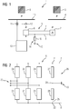
- FIG. 1 an installation 1 for transmitting electrical power is shown.
- the system 1 comprises a diode rectifier 2.
- the diode rectifier 2 is connected on the AC voltage side via a busbar 4 to a three-phase first AC voltage network 3.
- the diode rectifier 2 is connected on the DC voltage side via a DC voltage connection 5 to a modular multi-stage converter (MMC) 6.
- the DC voltage connection 5 comprises a first DC voltage pole 7 and a second DC voltage pole 8.
- the first DC voltage pole 7 is a positive DC voltage pole
- the second DC voltage pole 8 is a negative DC voltage pole.
- the MMC 6 is connected on the DC voltage side to the DC voltage connection 5 and on the AC voltage side via a busbar 10 to a three-phase second AC voltage network 9.
- the system 1 also includes a voltage measuring unit 11 and a current measuring unit 12 as well as a control unit 13 for regulating and activating the MMC 6.
- a filter unit 14 On the DC voltage side of the MMC 6, a filter unit 14 is provided which is set up to filter an AC voltage component in the DC power that is between the Diode rectifier 2 and the MMC 6 is transmitted.
- the filter unit 14 connects the MMC 6 via the second DC voltage pole 8 of the DC voltage connection 5 to a neutral point 15, which in the example shown is a ground connection.
- the filter unit 14 comprises a passive filter 16.
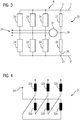
- FIG 2 shows a modular multi-stage converter (MMC) 6 for the system 1 of Figure 1 .
- MMC modular multi-stage converter
- the MMC 6 has a first DC voltage pole 21 and a second DC voltage pole 22.
- the first DC voltage pole 21 is connected to the first DC voltage pole 7 of the DC voltage connection 5.
- the second DC voltage pole 22 is correspondingly connected to the second DC voltage pole 8 of the DC voltage connection 5.
- the MMC 6 also has an AC voltage connection 23, which is set up to connect the MMC 6 to the three-phase AC voltage network 9. Between each of the two DC voltage poles 21, 22 and the AC voltage connection 23, six phase branches 24 of the same structure extend. The structure of a phase branch 24 is shown below in FIG Figure 5 detailed.
- a branch 25 of a filter unit extends between the first and the second DC voltage pole 21 and 22, respectively.
- the filter unit 26 comprises a first filter 27 and a second filter 28, which are arranged in series with one another.
- a potential point 29 between the two filters 27 and 28 is connected to the ground connection 15, which represents the neutral point of the AC voltage network 9.
- FIG 3 shows the MMC 6 with a filter unit 30.
- the filter unit 30 is largely the same as the filter unit 26 of FIG Figure 2 with the difference that the potential point 29 between the filters 27 and 28 of the filter unit 30 with a star point (in Figure 3 not shown in the figure) of a grounding transformer 31 is connected.
- the star point of the grounding transformer 31 represents the neutral point of the AC voltage network 9.
- the structure of the grounding transformer 31 known to those skilled in the art is shown below Figure 4 shown in more detail.
- the grounding transformer 31 comprises a first, a second and a third primary winding 32a, 32b, 32c, which are connected to the AC voltage connection 23 of the MMC 6.
- the primary windings 32a-c are connected to compensation windings 33a-c in a zigzag arrangement.
- the compensation windings 33a-c are connected to a star point 34 of the grounding transformer 31.
- the star point 34 can be galvanically connected to the potential point 29 of the filter unit.
- phase branch 24 of the MMC 6 is shown.
- the in Figure 5 The phase branch 24 shown extends between the first DC voltage pole 7 and the AC voltage connection 23 of the MMC 6.
- the phase branch 24 comprises a current measuring element 35 for measuring a branch current Iz as well as a series connection of similarly constructed two-pole switching modules 36.
- the number of switching modules 36 is basically arbitrary and depending on the respective application adapted what is in Figure 5 is indicated by the broken line 37.
- a smoothing choke 38 is arranged in a series connection with the switching modules 36. The structure of the switching modules 36 is described in the following Figures 7 and 8 detailed.
- FIG Figure 6 shows the structure of a filter 27 of the filter units 26 and 30.
- the filter 27 can also be used as a filter 16 of the filter unit 14 of FIG Figure 1 can be used.
- the filter 27 comprises a series connection of a filter capacitor 41 and a filter choke 42.
- the dimensioning and design of the capacitance C of the filter capacitor 41 and the inductance L of the filter choke 42 can be adapted to the respective application.
- C and L are adapted to a network frequency of the AC voltage network connected to the MMC 6 in such a way that this corresponds to the resonance frequency of the filter 27.
- a single filter choke and a single filter capacitor several chokes and / or capacitors connected in series or in parallel can also be provided.
- the second filter 28 of the filter units 26 and 30 is constructed in the same way as the filter 27, it also being possible for the arrangement of the filter capacitor 41 and the filter choke 42 to be interchanged.
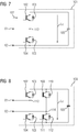
- FIG. 7 shows in detail a switching module in the form of a half-bridge circuit 101.
- the half-bridge circuit 101 has two connections X1 and X2.
- the connection X1 can, for example, connect the half-bridge circuit 101 to the connection X2 of a further half-bridge circuit, so that a series connection of the submodules is formed.
- the half-bridge circuit 101 comprises a first semiconductor switch 102 in the form of a bipolar transistor with an insulated gate electrode (IGBT), to which a freewheeling diode 103 is connected in anti-parallel.
- the half-bridge circuit 101 furthermore comprises a second semiconductor switch 104 in the form of an IGBT to which a freewheeling diode 105 is connected in anti-parallel.
- the forward direction of the two semiconductor switches 102 and 104 is rectified.
- the first connection X1 is arranged at a potential point 113 between the two semiconductor switches 102 and 104.
- the second connection X2 is connected to the emitter of the second semiconductor switch 104.
- An energy store in the form of a power capacitor 106 is arranged parallel to the two semiconductor switches 102, 104. With a suitable control of the semiconductor switches 102, 104, the capacitor 106 can be switched on or bridged with an operating current direction indicated by an arrow 107, so that either the voltage Uc dropping across the capacitor 106 or a voltage zero drops at the connections X1, X2.
- FIG Figure 8 An example of a switching module in the form of a full bridge circuit 108 is shown in FIG Figure 8 shown schematically.
- the full bridge circuit 108 has a first semiconductor switch 102 in the form of an IGBT, to which a freewheeling diode 103 is connected in anti-parallel, and a second semiconductor switch 104 in the form of an IGBT, to which a freewheeling diode 105 is connected in anti-parallel.
- the forward direction of the two semiconductor switches 102 and 104 is rectified.
- the full bridge circuit 108 comprises a third semiconductor switch 109 in the form of an IGBT, to which a freewheeling diode 110 is connected in anti-parallel, and a fourth semiconductor switch 111 in the form of an IGBT, to which a freewheeling diode 112 is connected in anti-parallel.
- the forward direction of the two semiconductor switches 109 and 111 is rectified.
- the semiconductor switches 102 and 104 with their associated freewheeling diodes 103, 105 thus form a series circuit that is connected in parallel to a series circuit formed by the semiconductor switches 109, 111 and the associated freewheeling diodes 110 and 112.
- An energy store in the form of a power capacitor 106 is arranged in parallel to the two series connections.
- the first connection X1 is arranged at a potential point 113 between the semiconductor switches 102, 104
- the second connection X2 is arranged at a potential point 114 between the semiconductor switches 109, 111.
- the voltage drop across the terminals X1, X2 can be generated, which corresponds to the voltage Uc dropping across the capacitor 106, the voltage dropping across the capacitor 106 but with opposite polarity or the voltage zero .
Landscapes
- Engineering & Computer Science (AREA)
- Power Engineering (AREA)
- Rectifiers (AREA)
Claims (6)
- Installation (1) de transport de puissance électrique, comprenant- un redresseur (2) unidirectionnel, qui peut être relié du côté de la tension alternative à un premier réseau (3) de tension alternative,- un onduleur (6) à commutation autonome, qui, du côté de la tension alternative, peut être relié à un deuxième réseau (9) de tension alternative,- une liaison (5) de tension continue, qui relie entre eux, du côté de la tension continue, le redresseur (2) et l'onduleur (6),dans lequel l'installation a, en outre, une unité (30) de filtrage, qui est reliée, du côté de la tension continue, à l'onduleur (6) et qui constitue un trajet de courant vers un point (34) neutre, le trajet de courant ayant une grande impédance pour un courant continu et une petite impédance pour un courant alternatif, ayant la fréquence d'oscillation fondamentale du deuxième réseau (9) de tension alternative, caractérisée en ce que l'unité (30) de filtrage comprend un circuit série d'une inductance (42) et d'une capacité (41), la capacité (41) et l'inductance (42) étant conçues pour accorder une fréquence de résonnance de l'unité (30) de filtrage à une fréquence de fonctionnement du deuxième réseau (9) de tension alternative, l'installation ayant un transformateur ( 31 ) à point étoile, en enroulement zigzag, qui est prévu pour la liaison avec le deuxième réseau (9) de tension alternative et le point neutre étant formé par un point ( 34 ) étoile du transformateur ( 31 ) à point étoile.
- Installation ( 1 ) suivant la revendication 1,
dans laquelle l'unité ( 30 ) de filtrage comprend exclusivement des composants ( 41, 42 ) de filtrage passifs. - Installation (1 ) suivant l'une des revendications précédentes,
dans laquelle l'unité ( 30 ) de filtrage comprend une branche ( 25 ) de courant, qui s'étend entre un pôle ( 21 ) positif de tension continue de l'onduleur ( 6 ) et un pôle ( 22 ) négatif de tension continue de l'onduleur ( 6 ), la branche ( 25 ) de courant comprenant un premier filtre ( 27 ) ayant un circuit série d'une première inductance ( 12 ) et d'une première capacité ( 41 ), ainsi qu'un deuxième filtre ( 28 ) ayant un circuit série d'une deuxième inductance ( 42 ) et d'une deuxième capacité ( 41 ), un point ( 29 ) de potentiel, entre le premier et le deuxième filtres ( 27, 28 ) étant relié au point ( 34 ) neutre. - Installation ( 1 ) suivant l'une des revendications précédentes,
dans lequel le redresseur ( 2 ) unidirectionnel est un redresseur à diode. - Installation ( 1 ) suivant l'une des revendications précédentes,
dans lequel l'onduleur ( 6 ) à commutation autonome est un onduleur modulaire à plusieurs étages. - Onduleur (6) modulaire à plusieurs étages, qui peut être relié, du côté de la tension alternative, à un réseau (9) de tension alternative, et du côté de la tension continue, à une liaison (15) de tension continue,
l'onduleur (6) à plusieurs étages ayant une unité (30) de filtrage, qui est reliée à un côté de la tension continue de l'onduleur (6) à plusieurs étages et qui constitue un trajet de courant vers un point (34) neutre, le trajet de courant ayant une grande impédance pour un courant continu et une petite impédance pour un courant alternatif ayant la fréquence d'oscillations fondamentale du réseau (9) de tension alternative, caractérisé en ce que l'unité (30) de filtrage comprend un circuit série d'une inductance (42) et d'une capacité (41), la capacité (41) et l'inductance (42) étant conçues pour accorder une fréquence de résonnance de l'unité (30) de filtrage à une fréquence de fonctionnement du deuxième réseau (9) de tension alternative, l'onduleur à plusieurs étages ayant un transformateur (31) à point étoile en enroulement en zigzag, qui est prévu pour la liaison avec le réseau (9) de tension alternative, et le point neutre étant formé par un point (34) étoile d'un transformateur (31) à point étoile.
Applications Claiming Priority (1)
| Application Number | Priority Date | Filing Date | Title |
|---|---|---|---|
| PCT/EP2016/076798 WO2018082786A1 (fr) | 2016-11-07 | 2016-11-07 | Système servant à transmettre une puissance électrique comprenant une unité de filtrage |
Publications (2)
| Publication Number | Publication Date |
|---|---|
| EP3513475A1 EP3513475A1 (fr) | 2019-07-24 |
| EP3513475B1 true EP3513475B1 (fr) | 2021-02-24 |
Family
ID=57326355
Family Applications (1)
| Application Number | Title | Priority Date | Filing Date |
|---|---|---|---|
| EP16797479.9A Active EP3513475B1 (fr) | 2016-11-07 | 2016-11-07 | Système servant à transmettre une puissance électrique comprenant une unité de filtrage |
Country Status (2)
| Country | Link |
|---|---|
| EP (1) | EP3513475B1 (fr) |
| WO (1) | WO2018082786A1 (fr) |
Families Citing this family (2)
| Publication number | Priority date | Publication date | Assignee | Title |
|---|---|---|---|---|
| DE102019214545B4 (de) * | 2019-09-24 | 2022-01-27 | Siemens Energy Global GmbH & Co. KG | Stromrichter und Verfahren zu dessen Betrieb |
| CN113098244B (zh) * | 2021-04-07 | 2022-05-06 | 全球能源互联网研究院有限公司 | 一种mmc换流器的桥臂电抗单元 |
Citations (1)
| Publication number | Priority date | Publication date | Assignee | Title |
|---|---|---|---|---|
| WO1991009451A1 (fr) * | 1989-12-07 | 1991-06-27 | Elin Energieversorgung Gesellschaft M.B.H. | Agencement de filtrage |
Family Cites Families (4)
| Publication number | Priority date | Publication date | Assignee | Title |
|---|---|---|---|---|
| DE10103031B4 (de) | 2001-01-24 | 2011-12-01 | Siemens Ag | Stromrichterschaltung mit verteilten Energiespeichern und Verfahren zur Steuerung einer derartigen Stromrichterschaltung |
| CA2622089A1 (fr) * | 2005-09-09 | 2007-03-15 | Siemens Aktiengesellschaft | Dispositif de transmission d'energie electrique |
| US8120202B2 (en) | 2010-10-25 | 2012-02-21 | General Electric Company | Electric power transmission system for wind turbine and wind turbine farm and method for operating same |
| EP2713494A1 (fr) * | 2012-09-28 | 2014-04-02 | Siemens Aktiengesellschaft | Dispositif d'alimentation en énergie pour l'alimentation de l'énergie électrique générée par l'énergie cinétique dans un réseau de distribution de courant triphasé |
-
2016
- 2016-11-07 EP EP16797479.9A patent/EP3513475B1/fr active Active
- 2016-11-07 WO PCT/EP2016/076798 patent/WO2018082786A1/fr unknown
Patent Citations (1)
| Publication number | Priority date | Publication date | Assignee | Title |
|---|---|---|---|---|
| WO1991009451A1 (fr) * | 1989-12-07 | 1991-06-27 | Elin Energieversorgung Gesellschaft M.B.H. | Agencement de filtrage |
Also Published As
| Publication number | Publication date |
|---|---|
| WO2018082786A1 (fr) | 2018-05-11 |
| EP3513475A1 (fr) | 2019-07-24 |
Similar Documents
| Publication | Publication Date | Title |
|---|---|---|
| EP3172823B1 (fr) | Convertisseur continu/continu comportant un transformateur | |
| EP2432109B1 (fr) | Commutateur modulaire pour un convertisseur électrique, convertisseur électrique et procédé de fonctionnement d'un convertisseur électrique | |
| EP2237404B1 (fr) | Onduleur avec deux ponts asymmetrics et une branche à roue libre découplante l'entrée du courant continu de la sortie du courant alternatif | |
| EP2107672A1 (fr) | Onduleur triphasé sans connexion entre le conducteur de neutre du réseau et le point milieu du circuit intermédiaire | |
| DE102005019215B4 (de) | Ausgangsfilter für einen gepulsten Stromrichter | |
| EP2586646B1 (fr) | Dispositif électrique d'alimentation en énergie pour dispositifs d'entraînement destiné au fonctionnement d'un véhicule sur rail sur des réseaux d'alimentation électriques | |
| WO2014206704A1 (fr) | Ensemble mutateur à mutateurs multi-étages câblés en parallèle et son procédé de commande | |
| DE102011086087A1 (de) | Elektrischer Umrichter | |
| EP2845303A1 (fr) | Convertisseur et procédés de conversion de tension | |
| EP0682401B1 (fr) | Dispositif pour la limitation de la pente de la tension de sortie d'un convertisseur auto-commuté | |
| CH693524A5 (de) | Einrichtung zur Begrenzung der Aenderungsgeschwindigkeit der Ausgangsgrössen eines über einen Gleichspannungszwischenkreis selbstgeführten mehrphasigen Umrichters. | |
| WO2016138949A1 (fr) | Convertisseur continu-continu | |
| EP3513475B1 (fr) | Système servant à transmettre une puissance électrique comprenant une unité de filtrage | |
| DE10303421A1 (de) | Strom-/Spannungswandleranordnung | |
| EP3652848B1 (fr) | Hacheur résonant | |
| WO2009098093A2 (fr) | Ensemble onduleur permettant l'injection d'énergie produite par voie photovoltaïque dans un réseau public | |
| EP0474060B1 (fr) | Convertisseur de courant alternatif à quatre quadrants | |
| EP3098958B1 (fr) | Disposition de convertisseurs à couplage capacitif | |
| EP3304718B1 (fr) | Convertisseur continu-continu pour hautes tensions | |
| EP3180844B1 (fr) | Ensemble convertisseur muni d'une unité de court-circuit ainsi que procédé de coupure d'une ligne à tension alternative | |
| DE4344709A1 (de) | Verfahren zur Umwandlung von unterschiedlich großen Gleich- oder Wechselspannungen in eine beliebig vorgegebene Spannung | |
| CH707447B1 (de) | Vorrichtung zur Gleichspannungswandlung für hohe Übersetzungsverhältnisse. | |
| EP3331118B1 (fr) | Installation de transfert d'énergie électrique | |
| WO2018113926A1 (fr) | Convertisseur | |
| EP3526889B1 (fr) | Ensemble inverseur avec un neutre à la terre |
Legal Events
| Date | Code | Title | Description |
|---|---|---|---|
| STAA | Information on the status of an ep patent application or granted ep patent |
Free format text: STATUS: UNKNOWN |
|
| STAA | Information on the status of an ep patent application or granted ep patent |
Free format text: STATUS: THE INTERNATIONAL PUBLICATION HAS BEEN MADE |
|
| PUAI | Public reference made under article 153(3) epc to a published international application that has entered the european phase |
Free format text: ORIGINAL CODE: 0009012 |
|
| STAA | Information on the status of an ep patent application or granted ep patent |
Free format text: STATUS: REQUEST FOR EXAMINATION WAS MADE |
|
| 17P | Request for examination filed |
Effective date: 20190412 |
|
| AK | Designated contracting states |
Kind code of ref document: A1 Designated state(s): AL AT BE BG CH CY CZ DE DK EE ES FI FR GB GR HR HU IE IS IT LI LT LU LV MC MK MT NL NO PL PT RO RS SE SI SK SM TR |
|
| AX | Request for extension of the european patent |
Extension state: BA ME |
|
| RIN1 | Information on inventor provided before grant (corrected) |
Inventor name: ALVAREZ VALENZUELA, RODRIGO ALONSO Inventor name: ANTES, ANDREAS Inventor name: PIESCHEL, MARTIN |
|
| DAV | Request for validation of the european patent (deleted) | ||
| DAX | Request for extension of the european patent (deleted) | ||
| STAA | Information on the status of an ep patent application or granted ep patent |
Free format text: STATUS: EXAMINATION IS IN PROGRESS |
|
| 17Q | First examination report despatched |
Effective date: 20200415 |
|
| GRAP | Despatch of communication of intention to grant a patent |
Free format text: ORIGINAL CODE: EPIDOSNIGR1 |
|
| STAA | Information on the status of an ep patent application or granted ep patent |
Free format text: STATUS: GRANT OF PATENT IS INTENDED |
|
| GRAJ | Information related to disapproval of communication of intention to grant by the applicant or resumption of examination proceedings by the epo deleted |
Free format text: ORIGINAL CODE: EPIDOSDIGR1 |
|
| STAA | Information on the status of an ep patent application or granted ep patent |
Free format text: STATUS: EXAMINATION IS IN PROGRESS |
|
| RIC1 | Information provided on ipc code assigned before grant |
Ipc: H02J 3/36 20060101ALN20200722BHEP Ipc: H02J 3/26 20060101ALI20200722BHEP Ipc: H02M 5/458 20060101ALI20200722BHEP Ipc: H02J 3/38 20060101ALN20200722BHEP Ipc: H02J 3/34 20060101ALI20200722BHEP Ipc: H02M 1/14 20060101ALI20200722BHEP Ipc: H02M 1/12 20060101AFI20200722BHEP Ipc: H02M 7/483 20070101ALN20200722BHEP |
|
| INTG | Intention to grant announced |
Effective date: 20200810 |
|
| REG | Reference to a national code |
Ref country code: DE Ref legal event code: R079 Ref document number: 502016012469 Country of ref document: DE Free format text: PREVIOUS MAIN CLASS: H02J0003260000 Ipc: H02M0001120000 |
|
| INTC | Intention to grant announced (deleted) | ||
| GRAP | Despatch of communication of intention to grant a patent |
Free format text: ORIGINAL CODE: EPIDOSNIGR1 |
|
| STAA | Information on the status of an ep patent application or granted ep patent |
Free format text: STATUS: GRANT OF PATENT IS INTENDED |
|
| RIC1 | Information provided on ipc code assigned before grant |
Ipc: H02M 1/14 20060101ALI20200910BHEP Ipc: H02J 3/36 20060101ALN20200910BHEP Ipc: H02J 3/34 20060101ALI20200910BHEP Ipc: H02M 7/483 20070101ALN20200910BHEP Ipc: H02J 3/26 20060101ALI20200910BHEP Ipc: H02M 5/458 20060101ALI20200910BHEP Ipc: H02M 1/12 20060101AFI20200910BHEP Ipc: H02J 3/38 20060101ALN20200910BHEP |
|
| INTG | Intention to grant announced |
Effective date: 20200929 |
|
| GRAS | Grant fee paid |
Free format text: ORIGINAL CODE: EPIDOSNIGR3 |
|
| GRAA | (expected) grant |
Free format text: ORIGINAL CODE: 0009210 |
|
| STAA | Information on the status of an ep patent application or granted ep patent |
Free format text: STATUS: THE PATENT HAS BEEN GRANTED |
|
| RAP1 | Party data changed (applicant data changed or rights of an application transferred) |
Owner name: SIEMENS ENERGY GLOBAL GMBH & CO. KG |
|
| AK | Designated contracting states |
Kind code of ref document: B1 Designated state(s): AL AT BE BG CH CY CZ DE DK EE ES FI FR GB GR HR HU IE IS IT LI LT LU LV MC MK MT NL NO PL PT RO RS SE SI SK SM TR |
|
| REG | Reference to a national code |
Ref country code: CH Ref legal event code: EP |
|
| REG | Reference to a national code |
Ref country code: DE Ref legal event code: R096 Ref document number: 502016012469 Country of ref document: DE |
|
| REG | Reference to a national code |
Ref country code: AT Ref legal event code: REF Ref document number: 1365737 Country of ref document: AT Kind code of ref document: T Effective date: 20210315 |
|
| REG | Reference to a national code |
Ref country code: IE Ref legal event code: FG4D Free format text: LANGUAGE OF EP DOCUMENT: GERMAN |
|
| REG | Reference to a national code |
Ref country code: LT Ref legal event code: MG9D |
|
| REG | Reference to a national code |
Ref country code: NL Ref legal event code: MP Effective date: 20210224 |
|
| PG25 | Lapsed in a contracting state [announced via postgrant information from national office to epo] |
Ref country code: FI Free format text: LAPSE BECAUSE OF FAILURE TO SUBMIT A TRANSLATION OF THE DESCRIPTION OR TO PAY THE FEE WITHIN THE PRESCRIBED TIME-LIMIT Effective date: 20210224 Ref country code: GR Free format text: LAPSE BECAUSE OF FAILURE TO SUBMIT A TRANSLATION OF THE DESCRIPTION OR TO PAY THE FEE WITHIN THE PRESCRIBED TIME-LIMIT Effective date: 20210525 Ref country code: HR Free format text: LAPSE BECAUSE OF FAILURE TO SUBMIT A TRANSLATION OF THE DESCRIPTION OR TO PAY THE FEE WITHIN THE PRESCRIBED TIME-LIMIT Effective date: 20210224 Ref country code: PT Free format text: LAPSE BECAUSE OF FAILURE TO SUBMIT A TRANSLATION OF THE DESCRIPTION OR TO PAY THE FEE WITHIN THE PRESCRIBED TIME-LIMIT Effective date: 20210624 Ref country code: NO Free format text: LAPSE BECAUSE OF FAILURE TO SUBMIT A TRANSLATION OF THE DESCRIPTION OR TO PAY THE FEE WITHIN THE PRESCRIBED TIME-LIMIT Effective date: 20210524 Ref country code: BG Free format text: LAPSE BECAUSE OF FAILURE TO SUBMIT A TRANSLATION OF THE DESCRIPTION OR TO PAY THE FEE WITHIN THE PRESCRIBED TIME-LIMIT Effective date: 20210524 Ref country code: LT Free format text: LAPSE BECAUSE OF FAILURE TO SUBMIT A TRANSLATION OF THE DESCRIPTION OR TO PAY THE FEE WITHIN THE PRESCRIBED TIME-LIMIT Effective date: 20210224 |
|
| PG25 | Lapsed in a contracting state [announced via postgrant information from national office to epo] |
Ref country code: NL Free format text: LAPSE BECAUSE OF FAILURE TO SUBMIT A TRANSLATION OF THE DESCRIPTION OR TO PAY THE FEE WITHIN THE PRESCRIBED TIME-LIMIT Effective date: 20210224 Ref country code: LV Free format text: LAPSE BECAUSE OF FAILURE TO SUBMIT A TRANSLATION OF THE DESCRIPTION OR TO PAY THE FEE WITHIN THE PRESCRIBED TIME-LIMIT Effective date: 20210224 Ref country code: PL Free format text: LAPSE BECAUSE OF FAILURE TO SUBMIT A TRANSLATION OF THE DESCRIPTION OR TO PAY THE FEE WITHIN THE PRESCRIBED TIME-LIMIT Effective date: 20210224 Ref country code: RS Free format text: LAPSE BECAUSE OF FAILURE TO SUBMIT A TRANSLATION OF THE DESCRIPTION OR TO PAY THE FEE WITHIN THE PRESCRIBED TIME-LIMIT Effective date: 20210224 Ref country code: SE Free format text: LAPSE BECAUSE OF FAILURE TO SUBMIT A TRANSLATION OF THE DESCRIPTION OR TO PAY THE FEE WITHIN THE PRESCRIBED TIME-LIMIT Effective date: 20210224 |
|
| PG25 | Lapsed in a contracting state [announced via postgrant information from national office to epo] |
Ref country code: IS Free format text: LAPSE BECAUSE OF FAILURE TO SUBMIT A TRANSLATION OF THE DESCRIPTION OR TO PAY THE FEE WITHIN THE PRESCRIBED TIME-LIMIT Effective date: 20210624 |
|
| PG25 | Lapsed in a contracting state [announced via postgrant information from national office to epo] |
Ref country code: CZ Free format text: LAPSE BECAUSE OF FAILURE TO SUBMIT A TRANSLATION OF THE DESCRIPTION OR TO PAY THE FEE WITHIN THE PRESCRIBED TIME-LIMIT Effective date: 20210224 Ref country code: EE Free format text: LAPSE BECAUSE OF FAILURE TO SUBMIT A TRANSLATION OF THE DESCRIPTION OR TO PAY THE FEE WITHIN THE PRESCRIBED TIME-LIMIT Effective date: 20210224 Ref country code: SM Free format text: LAPSE BECAUSE OF FAILURE TO SUBMIT A TRANSLATION OF THE DESCRIPTION OR TO PAY THE FEE WITHIN THE PRESCRIBED TIME-LIMIT Effective date: 20210224 |
|
| REG | Reference to a national code |
Ref country code: DE Ref legal event code: R097 Ref document number: 502016012469 Country of ref document: DE |
|
| PG25 | Lapsed in a contracting state [announced via postgrant information from national office to epo] |
Ref country code: DK Free format text: LAPSE BECAUSE OF FAILURE TO SUBMIT A TRANSLATION OF THE DESCRIPTION OR TO PAY THE FEE WITHIN THE PRESCRIBED TIME-LIMIT Effective date: 20210224 Ref country code: SK Free format text: LAPSE BECAUSE OF FAILURE TO SUBMIT A TRANSLATION OF THE DESCRIPTION OR TO PAY THE FEE WITHIN THE PRESCRIBED TIME-LIMIT Effective date: 20210224 Ref country code: RO Free format text: LAPSE BECAUSE OF FAILURE TO SUBMIT A TRANSLATION OF THE DESCRIPTION OR TO PAY THE FEE WITHIN THE PRESCRIBED TIME-LIMIT Effective date: 20210224 |
|
| PLBE | No opposition filed within time limit |
Free format text: ORIGINAL CODE: 0009261 |
|
| STAA | Information on the status of an ep patent application or granted ep patent |
Free format text: STATUS: NO OPPOSITION FILED WITHIN TIME LIMIT |
|
| PG25 | Lapsed in a contracting state [announced via postgrant information from national office to epo] |
Ref country code: ES Free format text: LAPSE BECAUSE OF FAILURE TO SUBMIT A TRANSLATION OF THE DESCRIPTION OR TO PAY THE FEE WITHIN THE PRESCRIBED TIME-LIMIT Effective date: 20210224 Ref country code: AL Free format text: LAPSE BECAUSE OF FAILURE TO SUBMIT A TRANSLATION OF THE DESCRIPTION OR TO PAY THE FEE WITHIN THE PRESCRIBED TIME-LIMIT Effective date: 20210224 |
|
| 26N | No opposition filed |
Effective date: 20211125 |
|
| PG25 | Lapsed in a contracting state [announced via postgrant information from national office to epo] |
Ref country code: SI Free format text: LAPSE BECAUSE OF FAILURE TO SUBMIT A TRANSLATION OF THE DESCRIPTION OR TO PAY THE FEE WITHIN THE PRESCRIBED TIME-LIMIT Effective date: 20210224 |
|
| PG25 | Lapsed in a contracting state [announced via postgrant information from national office to epo] |
Ref country code: IT Free format text: LAPSE BECAUSE OF FAILURE TO SUBMIT A TRANSLATION OF THE DESCRIPTION OR TO PAY THE FEE WITHIN THE PRESCRIBED TIME-LIMIT Effective date: 20210224 |
|
| PG25 | Lapsed in a contracting state [announced via postgrant information from national office to epo] |
Ref country code: IS Free format text: LAPSE BECAUSE OF FAILURE TO SUBMIT A TRANSLATION OF THE DESCRIPTION OR TO PAY THE FEE WITHIN THE PRESCRIBED TIME-LIMIT Effective date: 20210624 |
|
| PG25 | Lapsed in a contracting state [announced via postgrant information from national office to epo] |
Ref country code: MC Free format text: LAPSE BECAUSE OF FAILURE TO SUBMIT A TRANSLATION OF THE DESCRIPTION OR TO PAY THE FEE WITHIN THE PRESCRIBED TIME-LIMIT Effective date: 20210224 |
|
| REG | Reference to a national code |
Ref country code: CH Ref legal event code: PL |
|
| PG25 | Lapsed in a contracting state [announced via postgrant information from national office to epo] |
Ref country code: LU Free format text: LAPSE BECAUSE OF NON-PAYMENT OF DUE FEES Effective date: 20211107 Ref country code: BE Free format text: LAPSE BECAUSE OF NON-PAYMENT OF DUE FEES Effective date: 20211130 |
|
| REG | Reference to a national code |
Ref country code: BE Ref legal event code: MM Effective date: 20211130 |
|
| PG25 | Lapsed in a contracting state [announced via postgrant information from national office to epo] |
Ref country code: IE Free format text: LAPSE BECAUSE OF NON-PAYMENT OF DUE FEES Effective date: 20211107 |
|
| PG25 | Lapsed in a contracting state [announced via postgrant information from national office to epo] |
Ref country code: FR Free format text: LAPSE BECAUSE OF NON-PAYMENT OF DUE FEES Effective date: 20211130 |
|
| REG | Reference to a national code |
Ref country code: AT Ref legal event code: MM01 Ref document number: 1365737 Country of ref document: AT Kind code of ref document: T Effective date: 20211107 |
|
| PG25 | Lapsed in a contracting state [announced via postgrant information from national office to epo] |
Ref country code: AT Free format text: LAPSE BECAUSE OF NON-PAYMENT OF DUE FEES Effective date: 20211107 |
|
| PG25 | Lapsed in a contracting state [announced via postgrant information from national office to epo] |
Ref country code: CY Free format text: LAPSE BECAUSE OF FAILURE TO SUBMIT A TRANSLATION OF THE DESCRIPTION OR TO PAY THE FEE WITHIN THE PRESCRIBED TIME-LIMIT Effective date: 20210224 |
|
| PG25 | Lapsed in a contracting state [announced via postgrant information from national office to epo] |
Ref country code: LI Free format text: LAPSE BECAUSE OF NON-PAYMENT OF DUE FEES Effective date: 20220630 Ref country code: HU Free format text: LAPSE BECAUSE OF FAILURE TO SUBMIT A TRANSLATION OF THE DESCRIPTION OR TO PAY THE FEE WITHIN THE PRESCRIBED TIME-LIMIT; INVALID AB INITIO Effective date: 20161107 Ref country code: CH Free format text: LAPSE BECAUSE OF NON-PAYMENT OF DUE FEES Effective date: 20220630 |
|
| PGFP | Annual fee paid to national office [announced via postgrant information from national office to epo] |
Ref country code: GB Payment date: 20231121 Year of fee payment: 8 |
|
| P01 | Opt-out of the competence of the unified patent court (upc) registered |
Effective date: 20231222 |
|
| PGFP | Annual fee paid to national office [announced via postgrant information from national office to epo] |
Ref country code: DE Payment date: 20231127 Year of fee payment: 8 |
|
| PG25 | Lapsed in a contracting state [announced via postgrant information from national office to epo] |
Ref country code: MK Free format text: LAPSE BECAUSE OF FAILURE TO SUBMIT A TRANSLATION OF THE DESCRIPTION OR TO PAY THE FEE WITHIN THE PRESCRIBED TIME-LIMIT Effective date: 20210224 |