EP3460992A1 - Inverter for an electric machine, electric machine for a vehicle and method for operating an inverter - Google Patents
Inverter for an electric machine, electric machine for a vehicle and method for operating an inverter Download PDFInfo
- Publication number
- EP3460992A1 EP3460992A1 EP17192641.3A EP17192641A EP3460992A1 EP 3460992 A1 EP3460992 A1 EP 3460992A1 EP 17192641 A EP17192641 A EP 17192641A EP 3460992 A1 EP3460992 A1 EP 3460992A1
- Authority
- EP
- European Patent Office
- Prior art keywords
- unit
- inverter
- pulse sequences
- electric machine
- basic signal
- Prior art date
- Legal status (The legal status is an assumption and is not a legal conclusion. Google has not performed a legal analysis and makes no representation as to the accuracy of the status listed.)
- Granted
Links
- 238000000034 method Methods 0.000 title claims description 7
- 238000001208 nuclear magnetic resonance pulse sequence Methods 0.000 claims abstract description 44
- 238000004804 winding Methods 0.000 claims abstract description 20
- 230000005669 field effect Effects 0.000 description 5
- 238000010586 diagram Methods 0.000 description 4
- 239000004065 semiconductor Substances 0.000 description 4
- 230000008901 benefit Effects 0.000 description 3
- 230000001360 synchronised effect Effects 0.000 description 2
- 230000015572 biosynthetic process Effects 0.000 description 1
- 230000000903 blocking effect Effects 0.000 description 1
- 238000011217 control strategy Methods 0.000 description 1
- 230000009977 dual effect Effects 0.000 description 1
- 238000003786 synthesis reaction Methods 0.000 description 1
- 230000002123 temporal effect Effects 0.000 description 1
Images

Classifications
-
- H—ELECTRICITY
- H02—GENERATION; CONVERSION OR DISTRIBUTION OF ELECTRIC POWER
- H02M—APPARATUS FOR CONVERSION BETWEEN AC AND AC, BETWEEN AC AND DC, OR BETWEEN DC AND DC, AND FOR USE WITH MAINS OR SIMILAR POWER SUPPLY SYSTEMS; CONVERSION OF DC OR AC INPUT POWER INTO SURGE OUTPUT POWER; CONTROL OR REGULATION THEREOF
- H02M1/00—Details of apparatus for conversion
- H02M1/0043—Converters switched with a phase shift, i.e. interleaved
-
- H—ELECTRICITY
- H02—GENERATION; CONVERSION OR DISTRIBUTION OF ELECTRIC POWER
- H02P—CONTROL OR REGULATION OF ELECTRIC MOTORS, ELECTRIC GENERATORS OR DYNAMO-ELECTRIC CONVERTERS; CONTROLLING TRANSFORMERS, REACTORS OR CHOKE COILS
- H02P27/00—Arrangements or methods for the control of AC motors characterised by the kind of supply voltage
- H02P27/04—Arrangements or methods for the control of AC motors characterised by the kind of supply voltage using variable-frequency supply voltage, e.g. inverter or converter supply voltage
- H02P27/06—Arrangements or methods for the control of AC motors characterised by the kind of supply voltage using variable-frequency supply voltage, e.g. inverter or converter supply voltage using dc to ac converters or inverters
- H02P27/08—Arrangements or methods for the control of AC motors characterised by the kind of supply voltage using variable-frequency supply voltage, e.g. inverter or converter supply voltage using dc to ac converters or inverters with pulse width modulation
- H02P27/085—Arrangements or methods for the control of AC motors characterised by the kind of supply voltage using variable-frequency supply voltage, e.g. inverter or converter supply voltage using dc to ac converters or inverters with pulse width modulation wherein the PWM mode is adapted on the running conditions of the motor, e.g. the switching frequency
-
- H—ELECTRICITY
- H02—GENERATION; CONVERSION OR DISTRIBUTION OF ELECTRIC POWER
- H02M—APPARATUS FOR CONVERSION BETWEEN AC AND AC, BETWEEN AC AND DC, OR BETWEEN DC AND DC, AND FOR USE WITH MAINS OR SIMILAR POWER SUPPLY SYSTEMS; CONVERSION OF DC OR AC INPUT POWER INTO SURGE OUTPUT POWER; CONTROL OR REGULATION THEREOF
- H02M7/00—Conversion of ac power input into dc power output; Conversion of dc power input into ac power output
- H02M7/42—Conversion of dc power input into ac power output without possibility of reversal
- H02M7/44—Conversion of dc power input into ac power output without possibility of reversal by static converters
- H02M7/48—Conversion of dc power input into ac power output without possibility of reversal by static converters using discharge tubes with control electrode or semiconductor devices with control electrode
- H02M7/493—Conversion of dc power input into ac power output without possibility of reversal by static converters using discharge tubes with control electrode or semiconductor devices with control electrode the static converters being arranged for operation in parallel
-
- H—ELECTRICITY
- H02—GENERATION; CONVERSION OR DISTRIBUTION OF ELECTRIC POWER
- H02P—CONTROL OR REGULATION OF ELECTRIC MOTORS, ELECTRIC GENERATORS OR DYNAMO-ELECTRIC CONVERTERS; CONTROLLING TRANSFORMERS, REACTORS OR CHOKE COILS
- H02P25/00—Arrangements or methods for the control of AC motors characterised by the kind of AC motor or by structural details
- H02P25/16—Arrangements or methods for the control of AC motors characterised by the kind of AC motor or by structural details characterised by the circuit arrangement or by the kind of wiring
- H02P25/22—Multiple windings; Windings for more than three phases
-
- H—ELECTRICITY
- H03—ELECTRONIC CIRCUITRY
- H03D—DEMODULATION OR TRANSFERENCE OF MODULATION FROM ONE CARRIER TO ANOTHER
- H03D13/00—Circuits for comparing the phase or frequency of two mutually-independent oscillations
- H03D13/003—Circuits for comparing the phase or frequency of two mutually-independent oscillations in which both oscillations are converted by logic means into pulses which are applied to filtering or integrating means
-
- B—PERFORMING OPERATIONS; TRANSPORTING
- B60—VEHICLES IN GENERAL
- B60L—PROPULSION OF ELECTRICALLY-PROPELLED VEHICLES; SUPPLYING ELECTRIC POWER FOR AUXILIARY EQUIPMENT OF ELECTRICALLY-PROPELLED VEHICLES; ELECTRODYNAMIC BRAKE SYSTEMS FOR VEHICLES IN GENERAL; MAGNETIC SUSPENSION OR LEVITATION FOR VEHICLES; MONITORING OPERATING VARIABLES OF ELECTRICALLY-PROPELLED VEHICLES; ELECTRIC SAFETY DEVICES FOR ELECTRICALLY-PROPELLED VEHICLES
- B60L2210/00—Converter types
- B60L2210/40—DC to AC converters
- B60L2210/46—DC to AC converters with more than three phases
-
- B—PERFORMING OPERATIONS; TRANSPORTING
- B60—VEHICLES IN GENERAL
- B60L—PROPULSION OF ELECTRICALLY-PROPELLED VEHICLES; SUPPLYING ELECTRIC POWER FOR AUXILIARY EQUIPMENT OF ELECTRICALLY-PROPELLED VEHICLES; ELECTRODYNAMIC BRAKE SYSTEMS FOR VEHICLES IN GENERAL; MAGNETIC SUSPENSION OR LEVITATION FOR VEHICLES; MONITORING OPERATING VARIABLES OF ELECTRICALLY-PROPELLED VEHICLES; ELECTRIC SAFETY DEVICES FOR ELECTRICALLY-PROPELLED VEHICLES
- B60L2220/00—Electrical machine types; Structures or applications thereof
- B60L2220/50—Structural details of electrical machines
- B60L2220/58—Structural details of electrical machines with more than three phases
-
- H—ELECTRICITY
- H02—GENERATION; CONVERSION OR DISTRIBUTION OF ELECTRIC POWER
- H02M—APPARATUS FOR CONVERSION BETWEEN AC AND AC, BETWEEN AC AND DC, OR BETWEEN DC AND DC, AND FOR USE WITH MAINS OR SIMILAR POWER SUPPLY SYSTEMS; CONVERSION OF DC OR AC INPUT POWER INTO SURGE OUTPUT POWER; CONTROL OR REGULATION THEREOF
- H02M3/00—Conversion of dc power input into dc power output
- H02M3/02—Conversion of dc power input into dc power output without intermediate conversion into ac
- H02M3/04—Conversion of dc power input into dc power output without intermediate conversion into ac by static converters
- H02M3/10—Conversion of dc power input into dc power output without intermediate conversion into ac by static converters using discharge tubes with control electrode or semiconductor devices with control electrode
- H02M3/145—Conversion of dc power input into dc power output without intermediate conversion into ac by static converters using discharge tubes with control electrode or semiconductor devices with control electrode using devices of a triode or transistor type requiring continuous application of a control signal
- H02M3/155—Conversion of dc power input into dc power output without intermediate conversion into ac by static converters using discharge tubes with control electrode or semiconductor devices with control electrode using devices of a triode or transistor type requiring continuous application of a control signal using semiconductor devices only
- H02M3/156—Conversion of dc power input into dc power output without intermediate conversion into ac by static converters using discharge tubes with control electrode or semiconductor devices with control electrode using devices of a triode or transistor type requiring continuous application of a control signal using semiconductor devices only with automatic control of output voltage or current, e.g. switching regulators
- H02M3/158—Conversion of dc power input into dc power output without intermediate conversion into ac by static converters using discharge tubes with control electrode or semiconductor devices with control electrode using devices of a triode or transistor type requiring continuous application of a control signal using semiconductor devices only with automatic control of output voltage or current, e.g. switching regulators including plural semiconductor devices as final control devices for a single load
- H02M3/1584—Conversion of dc power input into dc power output without intermediate conversion into ac by static converters using discharge tubes with control electrode or semiconductor devices with control electrode using devices of a triode or transistor type requiring continuous application of a control signal using semiconductor devices only with automatic control of output voltage or current, e.g. switching regulators including plural semiconductor devices as final control devices for a single load with a plurality of power processing stages connected in parallel
- H02M3/1586—Conversion of dc power input into dc power output without intermediate conversion into ac by static converters using discharge tubes with control electrode or semiconductor devices with control electrode using devices of a triode or transistor type requiring continuous application of a control signal using semiconductor devices only with automatic control of output voltage or current, e.g. switching regulators including plural semiconductor devices as final control devices for a single load with a plurality of power processing stages connected in parallel switched with a phase shift, i.e. interleaved
-
- H—ELECTRICITY
- H02—GENERATION; CONVERSION OR DISTRIBUTION OF ELECTRIC POWER
- H02P—CONTROL OR REGULATION OF ELECTRIC MOTORS, ELECTRIC GENERATORS OR DYNAMO-ELECTRIC CONVERTERS; CONTROLLING TRANSFORMERS, REACTORS OR CHOKE COILS
- H02P2207/00—Indexing scheme relating to controlling arrangements characterised by the type of motor
- H02P2207/07—Doubly fed machines receiving two supplies both on the stator only wherein the power supply is fed to different sets of stator windings or to rotor and stator windings
-
- Y—GENERAL TAGGING OF NEW TECHNOLOGICAL DEVELOPMENTS; GENERAL TAGGING OF CROSS-SECTIONAL TECHNOLOGIES SPANNING OVER SEVERAL SECTIONS OF THE IPC; TECHNICAL SUBJECTS COVERED BY FORMER USPC CROSS-REFERENCE ART COLLECTIONS [XRACs] AND DIGESTS
- Y02—TECHNOLOGIES OR APPLICATIONS FOR MITIGATION OR ADAPTATION AGAINST CLIMATE CHANGE
- Y02T—CLIMATE CHANGE MITIGATION TECHNOLOGIES RELATED TO TRANSPORTATION
- Y02T10/00—Road transport of goods or passengers
- Y02T10/60—Other road transportation technologies with climate change mitigation effect
- Y02T10/64—Electric machine technologies in electromobility
-
- Y—GENERAL TAGGING OF NEW TECHNOLOGICAL DEVELOPMENTS; GENERAL TAGGING OF CROSS-SECTIONAL TECHNOLOGIES SPANNING OVER SEVERAL SECTIONS OF THE IPC; TECHNICAL SUBJECTS COVERED BY FORMER USPC CROSS-REFERENCE ART COLLECTIONS [XRACs] AND DIGESTS
- Y02—TECHNOLOGIES OR APPLICATIONS FOR MITIGATION OR ADAPTATION AGAINST CLIMATE CHANGE
- Y02T—CLIMATE CHANGE MITIGATION TECHNOLOGIES RELATED TO TRANSPORTATION
- Y02T10/00—Road transport of goods or passengers
- Y02T10/60—Other road transportation technologies with climate change mitigation effect
- Y02T10/72—Electric energy management in electromobility
Definitions
- the present invention relates to an inverter for an electric machine, comprising at least two parallelly connected power units each configured to provide a multiphase AC output to stator windings of the electric machine and a control unit configured to provide a set of pulse sequences to each power unit, wherein the phase positions of the sets of pulse sequences are interleaved to each other.
- the present invention relates to an electric machine for a vehicle and a method for operating an inverter.
- Inverters are widely used to convert a DC voltage into a multiphase AC output which supplies stator windings of an electric machine.
- the DC voltage is typically obtained from a high voltage battery and the multiphase AC output is provided to an electric machine for driving the electric vehicle.
- BEV battery electric vehicles
- the inverter has to provide high AC currents.
- each switching element comprises two or more semiconductor switches connected in parallel and controlled commonly by a control unit.
- this solution suffers from high effort for designing such a power unit individually for each application.
- the control unit provides a set of interleaved pulse sequences to each power unit.
- the control unit is able to compensate asymmetric currents between the power units.
- such an interleaved pulsing of the power units reduces ripples in a DC-link of the inverter.
- control unit is configured to vary a pulsing frequency of the sets of pulse sequences and to adjust the mutual phase position of each set of pulse sequences to the interleaved phase positions when varying the pulsing frequency.
- the invention is based upon the consideration to combine the techniques of an interleaved parallel inverter and an inverter with variable modulation frequency by enabling the control unit to actively adjust the mutual phase position of each set of pulse sequences.
- this allows the use of complex control schemes like synchronous modulation or pulse frequency wobbling while operating the inverter with two or more power units connected in parallel. This allows to benefit from the advantages of these control schemes when high torques, particularly for automotive applications, are required.
- the inverter allows a scalable design by using an appropriate number of, preferably similar or equal, power units controlled by one control unit.
- each power unit provides a three-phase AC output.
- the inverter may provide a number of output phases corresponding to the product of the number of power units and the number of output phases of each power unit.
- the electric machine may comprise a number of stator windings corresponding to the number of output phases of the inverter.
- the power units are structurally identical and/or configured to be operated separately.
- the power units may be integral units and/or configured to be removably mountable to the inverter.
- each power unit comprises a plurality of switching elements, e.g. semiconductor switching elements such as insulated gate bipolar transistors, insulated gate field-effect transistors or junction field-effect transistors.
- the switching elements of each power unit may be connected to half bridges corresponding to the number of output phases of the power unit.
- Each switching element may comprise a control terminal, such as a gate terminal, controllable by the control unit to switch according to one pulse sequence.
- the control unit may comprise a main unit configured to compute and/or to specify the values of the variable frequency over time.
- set of pulse sequences refers to the pulse sequences provided to the switching elements of one power unit.
- One set of pulse sequences may comprise a number of pulse sequences corresponding to the number of switching elements of one power unit.
- the term "interleaved" means a temporal offset between respective sets of pulse sequences.
- control unit comprises a modulation unit configured to provide the sets of pulse sequences by pulse width modulation.
- the modulation unit may thus have a number of input ports corresponding to the number of interleaved frequencies to be modulated.
- the number of interleaved frequencies may be equal to the number of power units.
- the modulation unit is configured to modulate a basic signal and to provide the obtained set of pulse sequences to a first power unit
- the control unit comprises a feedforward unit for each other power unit configured to adjust the phase position of the basic signal to the interleaved phase positions
- the modulation unit is configured to modulate the adjusted basic signal and to provide the obtained set of pulse sequences to the other power unit or power units.
- the variation of the pulsing frequency may thus be achieved by varying the basic frequency. Consequently, the first power unit may be controlled by the modulated basic signal and the at least one other power unit may be controlled by the modulated adjusted basic signal.
- the basic signal of the first power unit is used as reference for the other power units.
- the first power unit may thus be considered as a master power unit and the other power units as slave power units.
- the feedforward unit has a finite impulse response.
- the feedforward unit may adapt to frequency of the basic signal by performing at least one intermediate period.
- the adjusted basic signal may thus lag the basic signal.
- the modulation unit may be configured to perform a carrier-based pulse width modulation of the triangular basic signal and/or the adjusted triangular basic signal.
- the modulation unit may be configured to perform a space-vector pulse width modulation of the basic signal and/or the adjusted basic signal.
- the basic signal may be a certain input quantity processible by the modulation unit.
- the adjustment is performed within a predetermined number of periods, preferably within one period, after varying the frequency. This allows a very fast adaption of frequency variation.
- control unit may comprise at least one PLL unit configured to correct the phase position of a set of pulsing sequences depending on the actual phase position of the set of pulsing sequences and a predefined phase setpoint.
- the phase setpoint and the actual phase position may be signals provided by the controller's main unit.
- the adjustment of the phase position may be performed by the PLL unit as well.
- a PLL unit may be assigned to each or a feedforward unit, wherein the PLL unit and the feedforward unit are connected to correct the phase position of the adjusted basic signal. This allows a synthesis of the sets of pulse sequences with a highly precise phase progression.
- the present invention relates to an electric machine for a vehicle, comprising an inventive inverter and a plurality of stator winding arrangements each configured to be supplied by one power unit.
- the present invention relates to a method for operating an inverter for an electric machine, comprising at least two parallelly connected power units each providing a multiphase AC output to stator windings of the electric machine, wherein a set of pulse sequences is provided to each power unit, wherein the phase positions of the sets of pulse sequences are interleaved to each other, wherein a pulsing frequency of the sets of pulse sequences is varied and the mutual phase position of each set of pulse sequences is adjusted after varying the pulsing frequency.
- inventive inverter may apply to the inventive electric machine and the inventive method, so that advantages achieved by the inventive inverter may be achieved by the inventive electric machine and the inventive method as well.
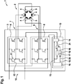
- Fig. 1 is a block diagram of an embodiment of an electric machine 1, comprising a stator 2 and an inverter 3.
- the electric machine 1 is particularly suitable to drive an electric vehicle, such as a battery electric vehicle (BEV) or a hybrid electric vehicle, wherein the inverter 3 is able to provide complex control schemes at high torques with low costs and mounting space.
- BEV battery electric vehicle
- a hybrid electric vehicle wherein the inverter 3 is able to provide complex control schemes at high torques with low costs and mounting space.
- the stator 2 comprises a first stator winding arrangement with three stator windings 4 and a second stator winding arrangement with three stator windings 5.
- the stator windings 4, 5 of each stator winding arrangements are delta connected, exemplarily.
- the inverter 3 comprises a first power 6 unit with a three-phase AC output 7 connected to the stator windings 4 of the first stator winding arrangement and a second power unit 8 with a three-phase AC output 9 connected to the stator windings 5 of the second stator winding arrangement.
- the power units 6, 8 are substantially identical, integral units and configured to be removably mountable to the inverter 3.
- the power units 6, 8 are connected in parallel to a DC-link 10 of the inverter 3.
- Each power unit 6, 8 comprises a plurality of switching elements 11 connected to half bridges.
- the switching elements 11 are semiconductor switching elements, e.g. insulated gate bipolar transistors, insulated gate field-effect transistors (IGBT), such as metal-oxide-semiconductor field-effect transistors (MOSFET), or junction field-effect transistors (JFET).
- IGBT insulated gate bipolar transistors
- MOSFET metal-oxide-semiconductor field-effect transistors
- JFET junction field-effect transistors
- Each switching element 11 comprises a control terminal 12, such as a gate terminal, by which the switching element 11 may be switched to its conducting and blocking switching state.
- each power unit 6, 8 comprises a plurality of driver units (not depicted) each connected in series to the control terminal 12 of a respective switching element 11.
- the inverter 3 comprises a control unit 13 configured to provide a set of pulse sequences to each power unit 6, 8.
- the pulse sequences are fed to a respective control terminal 12 via the driver unit for amplifying the pulse sequence such that the switching elements 11 provide the AC current to the AC outputs 7, 9.
- wirings between the control unit 13 and the switching elements 11 are not depicted for reasons of simplicity.
- the phase positions of the sets of pulse sequences are interleaved to each other according to their arrangement of the stator windings 4, 5.
- the control unit 13 comprises a modulation unit 14 configured to perform a carrier-based pulse width modulation (PWM) and to provide the sets of pulse sequences.
- PWM pulse width modulation
- the set of pulse sequences to the first power unit 6 results from a modulation of a basic signal 15 provided by a main unit 16 of the controller 13.
- the basic signal 15 is a triangular signal representing the actual frequency of the pulse width modulated pulse sequences.
- the main unit 16 is configured to vary frequency of the basic signal with respect to an implemented control strategy, such as synchronous modulation or wobbling of the pulsing frequency.
- the basic signal 15 is fed into a feedforward unit 17 of the controller 13.
- the feedforward unit has a finite impulse response and is configured to adjust the phase position of the basic signal 15 to the interleaved phase position of the set of pulse sequences for the second power unit 8.
- the controller comprises a PLL unit 18 configured to correct the phase position depending on the actual phase position 19 and a predefined phase setpoint 20 obtained from the main unit 16.
- the modulation unit 14 obtains the adjusted and corrected basic signal 21 and modulates it.
- the first power unit 6 may be considered as a reference or a master unit for the second power unit 8 working as a slave unit.
- Fig. 2 is a diagram depicting the basic signal 15 and the adjusted and corrected basic signal 21 over time t. As can be seen both signals have a mutual phase offset 22 resulting in sets of pulse sequences with a mutual phase position of 90°.
- the main unit 16 varies the frequency of the basic signal 15. This variation is detected by the feedforward unit 18 which adjusts the basic signal 15 to remain the phase position 22 within an intermediate period. Then, the adjusted basic signal is corrected by the PLL unit 18 resulting in the signal 23 which is modulated and used to control the second power unit 8, whereas the modulated basic signal 15 is used to control the first power unit 6.
- an inverter corresponding to the above-mentioned one, more than two power units are provided to supply a corresponding number of stator arrangements of the stator 2.
- Such a configuration corresponds to the embodiment of Fig. 1 in that additional second power units 8 and additional branches of feedforward units 17 and PLL units 18 are provided.
- the first power unit 6 works as master unit and the multiple second power units 8 work as slave units.
- the modulation unit 14 is configured to perform space-vector pulse width modulation of the basic signal, which is generally not a triangular function but a suitable input parameter for the modulation unit 14 and a correspondingly modified feedforward unit 18 and PLL unit 20.
Landscapes
- Engineering & Computer Science (AREA)
- Power Engineering (AREA)
- Inverter Devices (AREA)
- Control Of Ac Motors In General (AREA)
Abstract
Description
- The present invention relates to an inverter for an electric machine, comprising at least two parallelly connected power units each configured to provide a multiphase AC output to stator windings of the electric machine and a control unit configured to provide a set of pulse sequences to each power unit, wherein the phase positions of the sets of pulse sequences are interleaved to each other. Aside, the present invention relates to an electric machine for a vehicle and a method for operating an inverter.
- Inverters are widely used to convert a DC voltage into a multiphase AC output which supplies stator windings of an electric machine. With respect to automotive applications, particularly battery electric vehicles (BEV) and hybrid electric vehicles, the DC voltage is typically obtained from a high voltage battery and the multiphase AC output is provided to an electric machine for driving the electric vehicle. To generate high torque by the electric machine the inverter has to provide high AC currents. It has already been proposed to use a power unit, wherein each switching element comprises two or more semiconductor switches connected in parallel and controlled commonly by a control unit. However, this solution suffers from high effort for designing such a power unit individually for each application.
- Furthermore, it has been proposed to provide at least two power units each configured to provide a multiphase AC output to the electric machine, wherein the power units are connected in parallel. Typically, the control unit provides a set of interleaved pulse sequences to each power unit. With respect to simple pulse sequences, the control unit is able to compensate asymmetric currents between the power units. Advantageously, such an interleaved pulsing of the power units reduces ripples in a DC-link of the inverter. The paper by Bhattacharya, Subhadeep et. al "Interleaved SVPWM and DPWM for Dual Three-Phase Inverter-PMSM: An Automotive Application" (in: 2014 IEEE Transportation Electrification Conference and Expo (ITEC), Dearborn, MI, 2014, pp. 1-6) discloses such an inverter. However, a realization of more complex control schemes, particularly with a variable PWM frequency of the sets of pulse sequences, has not been proposed.
- Thus, it is an object of the present invention to provide a possibility to realize more complex control schemes for an inverter, particularly suitable to match the high automotive requirements concerning costs and mounting space.
- With respect to an inverter as initially described it is proposed according to the invention that the control unit is configured to vary a pulsing frequency of the sets of pulse sequences and to adjust the mutual phase position of each set of pulse sequences to the interleaved phase positions when varying the pulsing frequency.
- The invention is based upon the consideration to combine the techniques of an interleaved parallel inverter and an inverter with variable modulation frequency by enabling the control unit to actively adjust the mutual phase position of each set of pulse sequences. Advantageously, this allows the use of complex control schemes like synchronous modulation or pulse frequency wobbling while operating the inverter with two or more power units connected in parallel. This allows to benefit from the advantages of these control schemes when high torques, particularly for automotive applications, are required. With respect to costs and mounting space the inverter allows a scalable design by using an appropriate number of, preferably similar or equal, power units controlled by one control unit.
- Typically, each power unit provides a three-phase AC output. Thus, the inverter may provide a number of output phases corresponding to the product of the number of power units and the number of output phases of each power unit. The electric machine may comprise a number of stator windings corresponding to the number of output phases of the inverter. Preferably, the power units are structurally identical and/or configured to be operated separately. The power units may be integral units and/or configured to be removably mountable to the inverter.
- Typically, each power unit comprises a plurality of switching elements, e.g. semiconductor switching elements such as insulated gate bipolar transistors, insulated gate field-effect transistors or junction field-effect transistors. The switching elements of each power unit may be connected to half bridges corresponding to the number of output phases of the power unit. Each switching element may comprise a control terminal, such as a gate terminal, controllable by the control unit to switch according to one pulse sequence. The control unit may comprise a main unit configured to compute and/or to specify the values of the variable frequency over time. The term "set of pulse sequences" refers to the pulse sequences provided to the switching elements of one power unit. One set of pulse sequences may comprise a number of pulse sequences corresponding to the number of switching elements of one power unit. With respect to the present invention the term "interleaved" means a temporal offset between respective sets of pulse sequences.
- It is preferred that the control unit comprises a modulation unit configured to provide the sets of pulse sequences by pulse width modulation. The modulation unit may thus have a number of input ports corresponding to the number of interleaved frequencies to be modulated. The number of interleaved frequencies may be equal to the number of power units.
- According to an advantageous embodiment of the inventive inverter the modulation unit is configured to modulate a basic signal and to provide the obtained set of pulse sequences to a first power unit, wherein the control unit comprises a feedforward unit for each other power unit configured to adjust the phase position of the basic signal to the interleaved phase positions, wherein the modulation unit is configured to modulate the adjusted basic signal and to provide the obtained set of pulse sequences to the other power unit or power units. The variation of the pulsing frequency may thus be achieved by varying the basic frequency. Consequently, the first power unit may be controlled by the modulated basic signal and the at least one other power unit may be controlled by the modulated adjusted basic signal. With other words, the basic signal of the first power unit is used as reference for the other power units. The first power unit may thus be considered as a master power unit and the other power units as slave power units.
- Preferably, the feedforward unit has a finite impulse response. Particularly, the feedforward unit may adapt to frequency of the basic signal by performing at least one intermediate period. The adjusted basic signal may thus lag the basic signal.
- Besides, the modulation unit may be configured to perform a carrier-based pulse width modulation of the triangular basic signal and/or the adjusted triangular basic signal. As an alternative, the modulation unit may be configured to perform a space-vector pulse width modulation of the basic signal and/or the adjusted basic signal. In this case the basic signal may be a certain input quantity processible by the modulation unit.
- With respect to the inventive inverter, it is preferred that the adjustment is performed within a predetermined number of periods, preferably within one period, after varying the frequency. This allows a very fast adaption of frequency variation.
- Additionally, the control unit may comprise at least one PLL unit configured to correct the phase position of a set of pulsing sequences depending on the actual phase position of the set of pulsing sequences and a predefined phase setpoint. The phase setpoint and the actual phase position may be signals provided by the controller's main unit.
- Basically, the adjustment of the phase position may be performed by the PLL unit as well. However, due to the settling time of a PLL which may comprise several periods, it is preferred to use the above-mentioned feedforward unit for frequency adjustment. Particularly, a PLL unit may be assigned to each or a feedforward unit, wherein the PLL unit and the feedforward unit are connected to correct the phase position of the adjusted basic signal. This allows a synthesis of the sets of pulse sequences with a highly precise phase progression.
- Aside, the present invention relates to an electric machine for a vehicle, comprising an inventive inverter and a plurality of stator winding arrangements each configured to be supplied by one power unit.
- Furthermore, the present invention relates to a method for operating an inverter for an electric machine, comprising at least two parallelly connected power units each providing a multiphase AC output to stator windings of the electric machine, wherein a set of pulse sequences is provided to each power unit, wherein the phase positions of the sets of pulse sequences are interleaved to each other, wherein a pulsing frequency of the sets of pulse sequences is varied and the mutual phase position of each set of pulse sequences is adjusted after varying the pulsing frequency.
- All statements referring to the inventive inverter may apply to the inventive electric machine and the inventive method, so that advantages achieved by the inventive inverter may be achieved by the inventive electric machine and the inventive method as well.
- In the following, the invention is described in detail, whereby reference is made to the principal drawings, which show:
- Fig. 1
- a block diagram of an embodiment of an inventive electric machine with an inventive inverter; and
- Fig. 2
- a diagram depicting a basic signal and an adjusted basic signal over time.
-
Fig. 1 is a block diagram of an embodiment of an electric machine 1, comprising astator 2 and an inverter 3. The electric machine 1 is particularly suitable to drive an electric vehicle, such as a battery electric vehicle (BEV) or a hybrid electric vehicle, wherein the inverter 3 is able to provide complex control schemes at high torques with low costs and mounting space. - The
stator 2 comprises a first stator winding arrangement with threestator windings 4 and a second stator winding arrangement with threestator windings 5. Thestator windings - The inverter 3 comprises a
first power 6 unit with a three-phase AC output 7 connected to thestator windings 4 of the first stator winding arrangement and asecond power unit 8 with a three-phase AC output 9 connected to thestator windings 5 of the second stator winding arrangement. Thepower units power units link 10 of the inverter 3. - Each
power unit elements 11 connected to half bridges. The switchingelements 11 are semiconductor switching elements, e.g. insulated gate bipolar transistors, insulated gate field-effect transistors (IGBT), such as metal-oxide-semiconductor field-effect transistors (MOSFET), or junction field-effect transistors (JFET). Each switchingelement 11 comprises acontrol terminal 12, such as a gate terminal, by which theswitching element 11 may be switched to its conducting and blocking switching state. Additionally, eachpower unit control terminal 12 of arespective switching element 11. - Aside, the inverter 3 comprises a
control unit 13 configured to provide a set of pulse sequences to eachpower unit respective control terminal 12 via the driver unit for amplifying the pulse sequence such that the switchingelements 11 provide the AC current to the AC outputs 7, 9. InFig. 1 wirings between thecontrol unit 13 and theswitching elements 11 are not depicted for reasons of simplicity. The phase positions of the sets of pulse sequences are interleaved to each other according to their arrangement of thestator windings - The
control unit 13 comprises amodulation unit 14 configured to perform a carrier-based pulse width modulation (PWM) and to provide the sets of pulse sequences. The set of pulse sequences to thefirst power unit 6 results from a modulation of abasic signal 15 provided by amain unit 16 of thecontroller 13. Thebasic signal 15 is a triangular signal representing the actual frequency of the pulse width modulated pulse sequences. Accordingly, themain unit 16 is configured to vary frequency of the basic signal with respect to an implemented control strategy, such as synchronous modulation or wobbling of the pulsing frequency. - Additionally, the
basic signal 15 is fed into afeedforward unit 17 of thecontroller 13. The feedforward unit has a finite impulse response and is configured to adjust the phase position of thebasic signal 15 to the interleaved phase position of the set of pulse sequences for thesecond power unit 8. To stabilize the adjusted basic signal obtained from thefeedforward unit 17 the controller comprises aPLL unit 18 configured to correct the phase position depending on theactual phase position 19 and apredefined phase setpoint 20 obtained from themain unit 16. Themodulation unit 14 obtains the adjusted and correctedbasic signal 21 and modulates it. Thus, thefirst power unit 6 may be considered as a reference or a master unit for thesecond power unit 8 working as a slave unit. -
Fig. 2 is a diagram depicting thebasic signal 15 and the adjusted and correctedbasic signal 21 over time t. As can be seen both signals have a mutual phase offset 22 resulting in sets of pulse sequences with a mutual phase position of 90°. At thetime 23 themain unit 16 varies the frequency of thebasic signal 15. This variation is detected by thefeedforward unit 18 which adjusts thebasic signal 15 to remain thephase position 22 within an intermediate period. Then, the adjusted basic signal is corrected by thePLL unit 18 resulting in thesignal 23 which is modulated and used to control thesecond power unit 8, whereas the modulatedbasic signal 15 is used to control thefirst power unit 6. - According to another embodiment of an inverter corresponding to the above-mentioned one, more than two power units are provided to supply a corresponding number of stator arrangements of the
stator 2. Such a configuration corresponds to the embodiment ofFig. 1 in that additionalsecond power units 8 and additional branches offeedforward units 17 andPLL units 18 are provided. Thus, thefirst power unit 6 works as master unit and the multiplesecond power units 8 work as slave units. - According to another embodiment of an inverter corresponding to any of the above-mentioned ones, the
modulation unit 14 is configured to perform space-vector pulse width modulation of the basic signal, which is generally not a triangular function but a suitable input parameter for themodulation unit 14 and a correspondingly modifiedfeedforward unit 18 andPLL unit 20.
Claims (10)
- Inverter (3) for an electric machine (1), comprising at least two parallelly connected power units (6, 8) each configured to provide a multiphase AC output (7, 9) to stator windings (4, 5) of the electric machine (1) and a control unit (13) configured to provide a set of pulse sequences to each power unit (6, 8), wherein the phase positions of the sets of pulse signals are interleaved to each other, characterized in that the control unit (13) is configured to vary a pulsing frequency of the sets of pulse sequences and to adjust the mutual phase position of each set of pulse sequences to the interleaved phase positions when varying the pulsing frequency.
- Inverter (3) according to claim 1, characterized in that the control unit (13) comprises a modulation unit (14) configured to provide the sets of pulse sequences by pulse width modulation.
- Inverter (3) according to claim 2, characterized in that the modulation unit (14) is configured to modulate a basic signal (15) and to provide the obtained set of pulse sequences to a first power unit (6), wherein the control unit (13) comprises a feedforward unit (17) for each other power unit (8) configured to adjust the phase position of the basic signal (15) to the interleaved phase positions, wherein the modulation unit (14) is configured to modulate the adjusted basic signal (21) and to provide the obtained set of pulse sequences to the other power unit (8) or power units.
- Inverter (3) according to claim 3, characterized in that the feedforward unit (17) has a finite impulse response.
- Inverter (3) according to any of claims 2 to 4, characterized in that the modulation unit (14) is configured to perform a carrier-based pulse width modulation of the triangular basic signal (15) or a space-vector pulse width modulation of the basic signal (15).
- Inverter (3) according to any of the preceding claims, characterized in that the adjustment is performed within a predetermined number of periods, preferably within one period, after varying the frequency.
- Inverter (3) according to any of the preceding claims, characterized in that the control unit (13) comprises at least one PLL unit (18) configured to correct the phase position of a set of pulsing sequences depending on the actual phase position (19) of the set of pulsing sequences and a predefinded phase setpoint (20).
- Inverter (3) according to claim 7, characterized in that a PLL unit (18) is assigned to each or a feedforward unit (17), wherein the PLL unit (18) and the feedforward unit (17) are connected to correct the phase position of the adjusted basic signal (21).
- Electric machine (1) for a vehicle, comprising an inverter (3) according to any of claims 1 to 8 and a plurality of stator winding arrangements each configured to be supplied by one power unit (6, 8).
- Method for operating an inverter (3) for an electric machine (1), comprising at least two parallelly connected power units (6, 8) each providing a multiphase AC output (7, 9) to stator windings (4, 5) of the electric machine (1), wherein a set of pulse sequences is provided to each power unit (6, 8), wherein the phase positions of the sets of pulse sequences are interleaved to each other, wherein a pulsing frequency of the sets of pulse sequences is varied and the mutual phase position of each set of pulse sequences is adjusted after varying the pulsing frequency.
Priority Applications (3)
| Application Number | Priority Date | Filing Date | Title |
|---|---|---|---|
| EP17192641.3A EP3460992B1 (en) | 2017-09-22 | 2017-09-22 | Inverter for an electric machine, electric machine for a vehicle and method for operating an inverter |
| JP2018174718A JP7195836B2 (en) | 2017-09-22 | 2018-09-19 | Inverter for electrical device, electrical device for vehicle, and method for driving inverter |
| CN201811118020.3A CN109546921B (en) | 2017-09-22 | 2018-09-21 | Inverter for motor, motor for vehicle, and method of operating inverter |
Applications Claiming Priority (1)
| Application Number | Priority Date | Filing Date | Title |
|---|---|---|---|
| EP17192641.3A EP3460992B1 (en) | 2017-09-22 | 2017-09-22 | Inverter for an electric machine, electric machine for a vehicle and method for operating an inverter |
Publications (2)
| Publication Number | Publication Date |
|---|---|
| EP3460992A1 true EP3460992A1 (en) | 2019-03-27 |
| EP3460992B1 EP3460992B1 (en) | 2023-06-28 |
Family
ID=59968983
Family Applications (1)
| Application Number | Title | Priority Date | Filing Date |
|---|---|---|---|
| EP17192641.3A Active EP3460992B1 (en) | 2017-09-22 | 2017-09-22 | Inverter for an electric machine, electric machine for a vehicle and method for operating an inverter |
Country Status (2)
| Country | Link |
|---|---|
| EP (1) | EP3460992B1 (en) |
| JP (1) | JP7195836B2 (en) |
Citations (7)
| Publication number | Priority date | Publication date | Assignee | Title |
|---|---|---|---|---|
| US5933339A (en) * | 1998-03-23 | 1999-08-03 | Electric Boat Corporation | Modular static power converter connected in a multi-level, multi-phase, multi-circuit configuration |
| US20070262823A1 (en) * | 2006-05-01 | 2007-11-15 | Texas Instruments Incorporated | System and method for synchronizing multiple oscillators |
| US20100072928A1 (en) * | 2008-09-23 | 2010-03-25 | Gm Global Technology Operations, Inc. | Electrical system for pulse-width modulated control of a power inverter using phase-shifted carrier signals and related operating methods |
| US20110074326A1 (en) * | 2009-09-25 | 2011-03-31 | Ut-Battelle, Llc | Electrical motor/generator drive apparatus and method |
| US20120155139A1 (en) * | 2009-09-07 | 2012-06-21 | Koninklijke Philips Electronics N.V. | Electrical Energy Conversion Circuit Device |
| EP2594424A1 (en) * | 2010-07-14 | 2013-05-22 | Toyota Jidosha Kabushiki Kaisha | Controller for vehicle |
| US20140062433A1 (en) * | 2012-08-31 | 2014-03-06 | Maxim Integrated Products, Inc. | Multiphase switching converters operating over wide load ranges |
Family Cites Families (3)
| Publication number | Priority date | Publication date | Assignee | Title |
|---|---|---|---|---|
| JP3798670B2 (en) * | 2001-10-23 | 2006-07-19 | トヨタ自動車株式会社 | Inverter control device, inverter control method, storage medium, and program |
| JP5916526B2 (en) * | 2012-06-18 | 2016-05-11 | 三菱電機株式会社 | Power converter control device and multi-winding motor drive device |
| JP5593362B2 (en) * | 2012-09-28 | 2014-09-24 | 東芝三菱電機産業システム株式会社 | Multi-phase motor drive |
-
2017
- 2017-09-22 EP EP17192641.3A patent/EP3460992B1/en active Active
-
2018
- 2018-09-19 JP JP2018174718A patent/JP7195836B2/en active Active
Patent Citations (7)
| Publication number | Priority date | Publication date | Assignee | Title |
|---|---|---|---|---|
| US5933339A (en) * | 1998-03-23 | 1999-08-03 | Electric Boat Corporation | Modular static power converter connected in a multi-level, multi-phase, multi-circuit configuration |
| US20070262823A1 (en) * | 2006-05-01 | 2007-11-15 | Texas Instruments Incorporated | System and method for synchronizing multiple oscillators |
| US20100072928A1 (en) * | 2008-09-23 | 2010-03-25 | Gm Global Technology Operations, Inc. | Electrical system for pulse-width modulated control of a power inverter using phase-shifted carrier signals and related operating methods |
| US20120155139A1 (en) * | 2009-09-07 | 2012-06-21 | Koninklijke Philips Electronics N.V. | Electrical Energy Conversion Circuit Device |
| US20110074326A1 (en) * | 2009-09-25 | 2011-03-31 | Ut-Battelle, Llc | Electrical motor/generator drive apparatus and method |
| EP2594424A1 (en) * | 2010-07-14 | 2013-05-22 | Toyota Jidosha Kabushiki Kaisha | Controller for vehicle |
| US20140062433A1 (en) * | 2012-08-31 | 2014-03-06 | Maxim Integrated Products, Inc. | Multiphase switching converters operating over wide load ranges |
Also Published As
| Publication number | Publication date |
|---|---|
| JP7195836B2 (en) | 2022-12-26 |
| CN109546921A (en) | 2019-03-29 |
| EP3460992B1 (en) | 2023-06-28 |
| JP2019062731A (en) | 2019-04-18 |
Similar Documents
| Publication | Publication Date | Title |
|---|---|---|
| US7307401B2 (en) | Method and apparatus for PWM control of voltage source inverter | |
| AU2013408350B2 (en) | Multilevel drive half DC bus power supplies | |
| JP6394421B2 (en) | Drive device for semiconductor switching element | |
| CN108336943B (en) | Electric drive system and vehicle | |
| BR102014029257A2 (en) | power conversion system, method for operating parallel converters to drive a load, and non-transient computer readable media with computer executable instructions | |
| US9608540B2 (en) | Method and device for controlling an inverter | |
| US8730702B2 (en) | Very high efficiency three phase power converter | |
| TW201714397A (en) | Three-phase inverting apparatus and control method and paralleled power conversion system thereof | |
| WO2015094232A1 (en) | Control strategies for multilevel line regenerative drive | |
| US11581821B2 (en) | Multi-level inverter topologies for medium- and high-voltage applications | |
| CN104396134A (en) | Method and device for controlling an inverter | |
| WO2016201405A1 (en) | Modulation scheme for multiphase machines | |
| US9450438B2 (en) | Power device | |
| WO2020095802A1 (en) | Drive system | |
| KR101654755B1 (en) | Elective control of an alternating current motor or direct current motor | |
| EP3460992A1 (en) | Inverter for an electric machine, electric machine for a vehicle and method for operating an inverter | |
| CN109546921B (en) | Inverter for motor, motor for vehicle, and method of operating inverter | |
| US10003250B2 (en) | Modular converter circuit having sub-modules, which are operated in linear operation | |
| CN110581664A (en) | Control for electric power steering | |
| WO2018179234A1 (en) | H-bridge converter and power conditioner | |
| KR20190031747A (en) | Sinlge phase pwm converter for high-speed railway propulsion system using discontinuous modulation and method of controlling the same | |
| WO2012136946A3 (en) | Method for controlling a voltage inverter and associated device | |
| KR101955728B1 (en) | Inverter for driving motor | |
| Secrest et al. | Minimizing the Negative Impacts of Deadtime Insertion and Minimum Pulse Width in a 2-Level VSI | |
| JP7254198B2 (en) | Polyphase motor drive |
Legal Events
| Date | Code | Title | Description |
|---|---|---|---|
| PUAI | Public reference made under article 153(3) epc to a published international application that has entered the european phase |
Free format text: ORIGINAL CODE: 0009012 |
|
| STAA | Information on the status of an ep patent application or granted ep patent |
Free format text: STATUS: THE APPLICATION HAS BEEN PUBLISHED |
|
| AK | Designated contracting states |
Kind code of ref document: A1 Designated state(s): AL AT BE BG CH CY CZ DE DK EE ES FI FR GB GR HR HU IE IS IT LI LT LU LV MC MK MT NL NO PL PT RO RS SE SI SK SM TR |
|
| AX | Request for extension of the european patent |
Extension state: BA ME |
|
| STAA | Information on the status of an ep patent application or granted ep patent |
Free format text: STATUS: REQUEST FOR EXAMINATION WAS MADE |
|
| 17P | Request for examination filed |
Effective date: 20190919 |
|
| RBV | Designated contracting states (corrected) |
Designated state(s): AL AT BE BG CH CY CZ DE DK EE ES FI FR GB GR HR HU IE IS IT LI LT LU LV MC MK MT NL NO PL PT RO RS SE SI SK SM TR |
|
| STAA | Information on the status of an ep patent application or granted ep patent |
Free format text: STATUS: EXAMINATION IS IN PROGRESS |
|
| 17Q | First examination report despatched |
Effective date: 20200221 |
|
| STAA | Information on the status of an ep patent application or granted ep patent |
Free format text: STATUS: EXAMINATION IS IN PROGRESS |
|
| RAP3 | Party data changed (applicant data changed or rights of an application transferred) |
Owner name: VALEO EAUTOMOTIVE GERMANY GMBH |
|
| GRAP | Despatch of communication of intention to grant a patent |
Free format text: ORIGINAL CODE: EPIDOSNIGR1 |
|
| STAA | Information on the status of an ep patent application or granted ep patent |
Free format text: STATUS: GRANT OF PATENT IS INTENDED |
|
| INTG | Intention to grant announced |
Effective date: 20230119 |
|
| GRAS | Grant fee paid |
Free format text: ORIGINAL CODE: EPIDOSNIGR3 |
|
| GRAA | (expected) grant |
Free format text: ORIGINAL CODE: 0009210 |
|
| STAA | Information on the status of an ep patent application or granted ep patent |
Free format text: STATUS: THE PATENT HAS BEEN GRANTED |
|
| AK | Designated contracting states |
Kind code of ref document: B1 Designated state(s): AL AT BE BG CH CY CZ DE DK EE ES FI FR GB GR HR HU IE IS IT LI LT LU LV MC MK MT NL NO PL PT RO RS SE SI SK SM TR |
|
| REG | Reference to a national code |
Ref country code: CH Ref legal event code: EP |
|
| P01 | Opt-out of the competence of the unified patent court (upc) registered |
Effective date: 20230528 |
|
| REG | Reference to a national code |
Ref country code: AT Ref legal event code: REF Ref document number: 1583632 Country of ref document: AT Kind code of ref document: T Effective date: 20230715 |
|
| REG | Reference to a national code |
Ref country code: IE Ref legal event code: FG4D |
|
| REG | Reference to a national code |
Ref country code: DE Ref legal event code: R096 Ref document number: 602017070612 Country of ref document: DE |
|
| REG | Reference to a national code |
Ref country code: LT Ref legal event code: MG9D |
|
| PG25 | Lapsed in a contracting state [announced via postgrant information from national office to epo] |
Ref country code: SE Free format text: LAPSE BECAUSE OF FAILURE TO SUBMIT A TRANSLATION OF THE DESCRIPTION OR TO PAY THE FEE WITHIN THE PRESCRIBED TIME-LIMIT Effective date: 20230628 Ref country code: NO Free format text: LAPSE BECAUSE OF FAILURE TO SUBMIT A TRANSLATION OF THE DESCRIPTION OR TO PAY THE FEE WITHIN THE PRESCRIBED TIME-LIMIT Effective date: 20230928 |
|
| REG | Reference to a national code |
Ref country code: NL Ref legal event code: MP Effective date: 20230628 |
|
| REG | Reference to a national code |
Ref country code: AT Ref legal event code: MK05 Ref document number: 1583632 Country of ref document: AT Kind code of ref document: T Effective date: 20230628 |
|
| PG25 | Lapsed in a contracting state [announced via postgrant information from national office to epo] |
Ref country code: RS Free format text: LAPSE BECAUSE OF FAILURE TO SUBMIT A TRANSLATION OF THE DESCRIPTION OR TO PAY THE FEE WITHIN THE PRESCRIBED TIME-LIMIT Effective date: 20230628 Ref country code: NL Free format text: LAPSE BECAUSE OF FAILURE TO SUBMIT A TRANSLATION OF THE DESCRIPTION OR TO PAY THE FEE WITHIN THE PRESCRIBED TIME-LIMIT Effective date: 20230628 Ref country code: LV Free format text: LAPSE BECAUSE OF FAILURE TO SUBMIT A TRANSLATION OF THE DESCRIPTION OR TO PAY THE FEE WITHIN THE PRESCRIBED TIME-LIMIT Effective date: 20230628 Ref country code: LT Free format text: LAPSE BECAUSE OF FAILURE TO SUBMIT A TRANSLATION OF THE DESCRIPTION OR TO PAY THE FEE WITHIN THE PRESCRIBED TIME-LIMIT Effective date: 20230628 Ref country code: HR Free format text: LAPSE BECAUSE OF FAILURE TO SUBMIT A TRANSLATION OF THE DESCRIPTION OR TO PAY THE FEE WITHIN THE PRESCRIBED TIME-LIMIT Effective date: 20230628 Ref country code: GR Free format text: LAPSE BECAUSE OF FAILURE TO SUBMIT A TRANSLATION OF THE DESCRIPTION OR TO PAY THE FEE WITHIN THE PRESCRIBED TIME-LIMIT Effective date: 20230929 |
|
| PGFP | Annual fee paid to national office [announced via postgrant information from national office to epo] |
Ref country code: FR Payment date: 20230929 Year of fee payment: 7 Ref country code: DE Payment date: 20230911 Year of fee payment: 7 |
|
| PG25 | Lapsed in a contracting state [announced via postgrant information from national office to epo] |
Ref country code: FI Free format text: LAPSE BECAUSE OF FAILURE TO SUBMIT A TRANSLATION OF THE DESCRIPTION OR TO PAY THE FEE WITHIN THE PRESCRIBED TIME-LIMIT Effective date: 20230628 |
|
| PG25 | Lapsed in a contracting state [announced via postgrant information from national office to epo] |
Ref country code: SK Free format text: LAPSE BECAUSE OF FAILURE TO SUBMIT A TRANSLATION OF THE DESCRIPTION OR TO PAY THE FEE WITHIN THE PRESCRIBED TIME-LIMIT Effective date: 20230628 |
|
| PG25 | Lapsed in a contracting state [announced via postgrant information from national office to epo] |
Ref country code: ES Free format text: LAPSE BECAUSE OF FAILURE TO SUBMIT A TRANSLATION OF THE DESCRIPTION OR TO PAY THE FEE WITHIN THE PRESCRIBED TIME-LIMIT Effective date: 20230628 |
|
| PG25 | Lapsed in a contracting state [announced via postgrant information from national office to epo] |
Ref country code: IS Free format text: LAPSE BECAUSE OF FAILURE TO SUBMIT A TRANSLATION OF THE DESCRIPTION OR TO PAY THE FEE WITHIN THE PRESCRIBED TIME-LIMIT Effective date: 20231028 |
|
| PG25 | Lapsed in a contracting state [announced via postgrant information from national office to epo] |
Ref country code: SM Free format text: LAPSE BECAUSE OF FAILURE TO SUBMIT A TRANSLATION OF THE DESCRIPTION OR TO PAY THE FEE WITHIN THE PRESCRIBED TIME-LIMIT Effective date: 20230628 Ref country code: SK Free format text: LAPSE BECAUSE OF FAILURE TO SUBMIT A TRANSLATION OF THE DESCRIPTION OR TO PAY THE FEE WITHIN THE PRESCRIBED TIME-LIMIT Effective date: 20230628 Ref country code: RO Free format text: LAPSE BECAUSE OF FAILURE TO SUBMIT A TRANSLATION OF THE DESCRIPTION OR TO PAY THE FEE WITHIN THE PRESCRIBED TIME-LIMIT Effective date: 20230628 Ref country code: PT Free format text: LAPSE BECAUSE OF FAILURE TO SUBMIT A TRANSLATION OF THE DESCRIPTION OR TO PAY THE FEE WITHIN THE PRESCRIBED TIME-LIMIT Effective date: 20231030 Ref country code: IS Free format text: LAPSE BECAUSE OF FAILURE TO SUBMIT A TRANSLATION OF THE DESCRIPTION OR TO PAY THE FEE WITHIN THE PRESCRIBED TIME-LIMIT Effective date: 20231028 Ref country code: ES Free format text: LAPSE BECAUSE OF FAILURE TO SUBMIT A TRANSLATION OF THE DESCRIPTION OR TO PAY THE FEE WITHIN THE PRESCRIBED TIME-LIMIT Effective date: 20230628 Ref country code: EE Free format text: LAPSE BECAUSE OF FAILURE TO SUBMIT A TRANSLATION OF THE DESCRIPTION OR TO PAY THE FEE WITHIN THE PRESCRIBED TIME-LIMIT Effective date: 20230628 Ref country code: CZ Free format text: LAPSE BECAUSE OF FAILURE TO SUBMIT A TRANSLATION OF THE DESCRIPTION OR TO PAY THE FEE WITHIN THE PRESCRIBED TIME-LIMIT Effective date: 20230628 Ref country code: AT Free format text: LAPSE BECAUSE OF FAILURE TO SUBMIT A TRANSLATION OF THE DESCRIPTION OR TO PAY THE FEE WITHIN THE PRESCRIBED TIME-LIMIT Effective date: 20230628 |
|
| PG25 | Lapsed in a contracting state [announced via postgrant information from national office to epo] |
Ref country code: PL Free format text: LAPSE BECAUSE OF FAILURE TO SUBMIT A TRANSLATION OF THE DESCRIPTION OR TO PAY THE FEE WITHIN THE PRESCRIBED TIME-LIMIT Effective date: 20230628 |
|
| REG | Reference to a national code |
Ref country code: DE Ref legal event code: R097 Ref document number: 602017070612 Country of ref document: DE |
|
| PG25 | Lapsed in a contracting state [announced via postgrant information from national office to epo] |
Ref country code: DK Free format text: LAPSE BECAUSE OF FAILURE TO SUBMIT A TRANSLATION OF THE DESCRIPTION OR TO PAY THE FEE WITHIN THE PRESCRIBED TIME-LIMIT Effective date: 20230628 |
|
| REG | Reference to a national code |
Ref country code: CH Ref legal event code: PL |
|
| PLBE | No opposition filed within time limit |
Free format text: ORIGINAL CODE: 0009261 |
|
| STAA | Information on the status of an ep patent application or granted ep patent |
Free format text: STATUS: NO OPPOSITION FILED WITHIN TIME LIMIT |
|
| PG25 | Lapsed in a contracting state [announced via postgrant information from national office to epo] |
Ref country code: LU Free format text: LAPSE BECAUSE OF NON-PAYMENT OF DUE FEES Effective date: 20230922 |