EP3444146B1 - Energy absorption structure - Google Patents
Energy absorption structure Download PDFInfo
- Publication number
- EP3444146B1 EP3444146B1 EP16898647.9A EP16898647A EP3444146B1 EP 3444146 B1 EP3444146 B1 EP 3444146B1 EP 16898647 A EP16898647 A EP 16898647A EP 3444146 B1 EP3444146 B1 EP 3444146B1
- Authority
- EP
- European Patent Office
- Prior art keywords
- energy
- absorbing
- absorbing member
- load
- members
- Prior art date
- Legal status (The legal status is an assumption and is not a legal conclusion. Google has not performed a legal analysis and makes no representation as to the accuracy of the status listed.)
- Active
Links
- 238000010521 absorption reaction Methods 0.000 title description 11
- 239000012783 reinforcing fiber Substances 0.000 claims description 21
- 239000011347 resin Substances 0.000 claims description 11
- 229920005989 resin Polymers 0.000 claims description 11
- 238000003780 insertion Methods 0.000 description 25
- 230000037431 insertion Effects 0.000 description 25
- 230000002093 peripheral effect Effects 0.000 description 20
- 230000002787 reinforcement Effects 0.000 description 19
- 238000006073 displacement reaction Methods 0.000 description 4
- 239000012141 concentrate Substances 0.000 description 3
- 230000000694 effects Effects 0.000 description 3
- 230000007704 transition Effects 0.000 description 3
- 239000000853 adhesive Substances 0.000 description 2
- 230000001070 adhesive effect Effects 0.000 description 2
- 230000002708 enhancing effect Effects 0.000 description 2
- 239000011159 matrix material Substances 0.000 description 2
- 238000005192 partition Methods 0.000 description 2
- 229920000049 Carbon (fiber) Polymers 0.000 description 1
- 239000004917 carbon fiber Substances 0.000 description 1
- 230000001419 dependent effect Effects 0.000 description 1
- 210000003195 fascia Anatomy 0.000 description 1
- 238000005470 impregnation Methods 0.000 description 1
- 239000000463 material Substances 0.000 description 1
- 238000012986 modification Methods 0.000 description 1
- 230000004048 modification Effects 0.000 description 1
Images


Classifications
-
- B—PERFORMING OPERATIONS; TRANSPORTING
- B60—VEHICLES IN GENERAL
- B60R—VEHICLES, VEHICLE FITTINGS, OR VEHICLE PARTS, NOT OTHERWISE PROVIDED FOR
- B60R19/00—Wheel guards; Radiator guards, e.g. grilles; Obstruction removers; Fittings damping bouncing force in collisions
- B60R19/02—Bumpers, i.e. impact receiving or absorbing members for protecting vehicles or fending off blows from other vehicles or objects
- B60R19/24—Arrangements for mounting bumpers on vehicles
- B60R19/26—Arrangements for mounting bumpers on vehicles comprising yieldable mounting means
- B60R19/34—Arrangements for mounting bumpers on vehicles comprising yieldable mounting means destroyed upon impact, e.g. one-shot type
-
- B—PERFORMING OPERATIONS; TRANSPORTING
- B60—VEHICLES IN GENERAL
- B60R—VEHICLES, VEHICLE FITTINGS, OR VEHICLE PARTS, NOT OTHERWISE PROVIDED FOR
- B60R19/00—Wheel guards; Radiator guards, e.g. grilles; Obstruction removers; Fittings damping bouncing force in collisions
- B60R19/02—Bumpers, i.e. impact receiving or absorbing members for protecting vehicles or fending off blows from other vehicles or objects
- B60R19/18—Bumpers, i.e. impact receiving or absorbing members for protecting vehicles or fending off blows from other vehicles or objects characterised by the cross-section; Means within the bumper to absorb impact
Definitions
- the present invention relates to an energy-absorbing structure that uses an energy-absorbing member made of fiber-reinforced resin.
- Patent Document 1 discloses an energy-absorbing member made of fiber-reinforced resin that is used in a front side member of the front frame structure of a vehicle body. At the time of a front-end collision of a vehicle the collision load acts on the energy-absorbing member, and the collision energy is absorbed by the crushing of the energy-absorbing member.
- US 6 601 886 B1 and JP 2005 247096 A each disclose an energy-absorbing structure comprising: a frame member forming a part of a vehicle body framework; an energy-absorbing member formed from fiber-reinforced resin and provided at an end portion of the frame member; a load-receiving member provided on the energy-absorbing member on a side opposite of the frame member; and a tearing element provided adjacent an end portion of the energy-absorbing member that corresponds to at least one of the load-receiving member and the frame member so as to tear the energy-absorbing member upon an impact load being inputted from the load-receiving member toward the energy-absorbing member, wherein reinforcing fibers that extend in a direction intersecting an input direction of the impact load in the energy-absorbing member, and that are severed by the tearing element upon the energy-absorbing member being torn.
- Patent Document 1 Japanese Patent No. 4440683
- An energy-absorbing member made of fiber-reinforced resin absorbs collision energy by means of the deformation of a matrix resin with impregnated reinforcing fibers at the time that the energy-absorbing member is crushed.
- the reinforcing fibers themselves do not readily rupture, the energy absorption efficiency can be further enhanced by causing the reinforcing fibers to rupture.
- an object of the present invention is to further increase the energy absorption efficiency of an energy-absorbing member made of a fiber-reinforced resin.
- a tearing element which tears the energy-absorbing member when a collision load is input from a load-receiving member onto the energy-absorbing member, is provided adjacent the end portion of the energy-absorbing member that corresponds to at least one of the load-receiving member and a frame member.
- the tearing element tears the energy-absorbing member.
- the reinforcing fibers that extend in a direction that intersects the input direction of the impact load are severed, the energy absorption efficiency is further enhanced.
- FIG. 1 illustrates the lower portion of a vehicle body equipped with energy-absorbing members 1 according to a first embodiment of the present invention.
- the energy-absorbing members 1 are a fiber-reinforced resin material formed by impregnating reinforcing fibers, for example carbon fibers, in a matrix resin that is a resin for impregnation.
- the direction indicated by the arrow FR is the front of the vehicle body
- the direction indicated by the arrow LH is the left side of the vehicle body
- the direction indicated by the arrow UP is the up direction of the vehicle body.
- a pair of left and right front side members 3 are disposed on both sides of the front of the vehicle body in the vehicle width direction, along the longitudinal direction of the vehicle body.
- the front side members 3 each constitutes a frame member that forms the frame of the vehicle body and bends downward adjacent the location corresponding to the dash panel 5 and is joined to the lower surface of the floor panel 7.
- the dash panel 5 separates the vehicle cabin 9 and the engine compartment 11.
- Side sills 13 are disposed on both sides of the floor panel 7 in the vehicle width direction along the longitudinal direction of the vehicle body, and a hood ledge panels 15 are disposed on the upper portion of the front side members 3 on the engine compartment side.
- the energy-absorbing members 1 are attached to the front-end portion of the front side members 3.
- a bumper reinforcement 17 is attached to the front-end portion of the energy-absorbing member 1 on the opposite side of the front side members 3.
- the bumper reinforcement 17 is disposed along the vehicle width direction, and both ends thereof project farther outwardly in the vehicle width direction than the energy-absorbing member 1.
- a bumper fascia is attached to the bumper reinforcement 17.
- the front side members 3 are formed in the shape of a quadrangular prism, and includes a front-end flange 3f at the front-end portion on the energy-absorbing member 1 side, as illustrated in Figure 2 .
- a rear-end flange 1f is provided on the rear-end portion of the energy-absorbing member 1 on the side with the front side members 3.
- the front side members 3 and the energy-absorbing members 1 are fixed by causing the front-end flange 3f and the rear-end flange 1f to abut against each other and fastening them with a plurality of nuts 21 and a plurality of bolts 19.
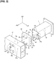
- the energy-absorbing members 1 and the bumper reinforcement 17 are fixed via connecting members 23, as illustrated in Figures 2 and 3 .
- the bumper reinforcement 17 and the connecting members 23 constitute a load-receiving member.
- the energy-absorbing members 1 each have the shape of a quadrangular prism tube, in the same manner as the front side members 3, as illustrated in Figure 3 .
- the connecting members 23 have a quadrangular shape that is larger than the energy-absorbing members 1 in a front view as seen from the front of the vehicle body.
- the connecting members 23 include an end surface portion 25 that abuts the rear surface of the bumper reinforcement 17, and side wall portions 27 that are bent from the four peripheral edges of the end surface portion 25 and that project toward the energy-absorbing member 1.
- the inner side of the bent portion between the end surface portion 25 and the side wall portions 27 forms a concave curved surface portion 29 over the entire perimeter, as illustrated in Figure 2 .
- the bumper reinforcement 17 is a hollow member whose cross-sectional shape is long vertically and has a partition wall 31 in the center in the vertical direction, and spaces having a cross section that is essentially square are formed above and below the partition wall 31.
- Four through-holes 17a are provided on the rear surface of the bumper reinforcement 17, and stud bolts 33 are provided on the end surface portion 25 of the connecting members 23 corresponding to the through-holes 17a.
- the bumper reinforcement 17 and the connecting members 23 are fixed and integrated by inserting the stud bolts 33 into the through-holes 17a, and fastening nuts 35 to the stud bolts 33 by utilizing working holes 17b on the front surface.
- the connecting members 23 When the connecting members 23 are fastened to the energy-absorbing members 1, the four side wall portions 27 in the periphery of the connecting members 23 are attached, so as to cover the peripheral edges of the front-end portion of the energy-absorbing members 1 from the outside. At that time, the side-wall portions 27 of the connecting members 23 overlap the side surfaces 37 as the surface portions of the energy-absorbing members 1 from the outer side adjacent the front-end portion to form overlapping portions 39, as illustrated in Figure 2 . In the overlapping portions 39, the side-wall portions 27 of the connecting members 23 and the side surfaces 37 of the energy-absorbing members 1 overlap in an orthogonal direction that intersects the input direction of the impact load, which is described below.
- a plurality of bolt insertion holes 37a are formed that extend through the side surfaces 37 of the energy-absorbing members 1 in the overlapping portions 39, and nuts 41 are attached on the inner sides of the side surfaces 37 in the periphery of the bolt insertion holes 37a.
- Bolt insertion holes 27a are formed that pass through the side wall portions 27 of the connecting members 23 corresponding to the bolt insertion holes 37a.
- the connecting members 23 and the energy-absorbing members 1 are fixed by inserting bolts 43 as fasteners into the bolt insertion holes 27a, 37a and fastening the bolts to the nuts 41, as illustrated in Figure 2 .
- the bolt insertion holes 27a, 37a constitute mounting holes, which extend through in the overlapping direction of the overlapping portions 39.
- a gap is formed between peripheral front ends 1a of the energy-absorbing members 1 and the end surface portions 25 of the connecting members 23, as illustrated in Figure 2 .
- the curved surface portions 29 of the connecting members 23 are positioned in front of the peripheral front ends 1a of the energy-absorbing members 1, and the peripheral front ends 1a and the curved surface portions 29 face each other.
- the curved surface portions 29 each have a cross section in the form of a quarter arc of a circle.
- the outer surfaces of the side surfaces 37 of the energy-absorbing members 1 are essentially positioned on a line tangent to the end portion of the arc.
- the impact load that is received by the bumper reinforcement 17 when the automobile undergoes a front-end collision is transmitted to the energy-absorbing members 1 via the connecting members 23.
- the energy-absorbing members 1 are crushed and deformed between the bumper reinforcement 17 and the front side members 3, thereby absorbing the impact.
- the impact load is applied to the energy-absorbing members 1 via the fastening portion configured by the bolts 43 of the overlapping portions 39.
- the shaft portions 43a of the bolts 43 are inserted into the bolt insertion holes 27a, 37a.
- the shaft portions 43a of the bolts 43 concentrate the stress in the bolt insertion holes 37a with respect to the energy-absorbing members 1 and becomes the point of origin when the energy-absorbing members 1 is crushed.
- the bolts 43 are provided in two or three locations on one side surface 37 of the energy-absorbing members 1.
- the impact load that is concentrated at and imparted to the bolt insertion holes 37a reaches the side surfaces 37 of the energy-absorbing members 1 for each of the plurality of the bolt insertion holes 37a, as indicated by the arrows P.
- the energy-absorbing members 1 are crushed and torn into multiple pieces along the load input direction with the bolt insertion holes 37a as the points of origin, due to the impact load that is imparted to each of the plurality of the bolt insertion holes 37a. That is, the bolts 43 are provided adjacent the end portion of the energy-absorbing members 1 and function as a tearing element that tears the energy-absorbing members 1 along the load input direction.
- the connecting members 23 moves in the direction toward the front side members 3 and transitions from the state before the impact load is received shown in Figure 5 to the state shown in Figure 6 , so as to crush the energy-absorbing members 1.
- the energy-absorbing members 1 absorb the impact by the inward displacement of the peripheral front ends 1a while being guided by the curved surface portions 29 of the connecting members 23 over the entire perimeter.
- stud bolts 33 that are similar to those of the connecting members 23 in Figure 3 are omitted.
- reinforcing fibers 47 indicated by the chain double-dashed lines are arranged so as to extend in a direction that intersects the load input direction, which is essentially the same direction as that indicated by the arrows P, at, for example, an approximately 45° angle, as illustrated in Figure 4 .
- the reinforcing fibers 47 are also severed, thereby absorbing the impact load.
- the energy absorption efficiency of the energy-absorbing members 1 is increased.
- Figure 4 and Figure 11 which is described below, only a portion of the reinforcing fibers 47 is shown, but in fact, the reinforcing fibers 47 are provided over the entirety of the energy-absorbing members 1.
- a tearing element that tears the energy-absorbing member 1 is composed of the bolts 43 that fasten and fix the energy-absorbing member 1 and the connecting member 23 on the side of the bumper reinforcement 17.
- the energy-absorbing members 1 have a tubular form, and the side wall portions 27 of the connecting members 23 are attached so as to cover the outer perimeter sides of the tubular energy-absorbing members 1 to form the overlapping portion 39.
- the energy-absorbing members 1 are crushed essentially uniformly over the entire perimeter between the connecting members 23 and the energy-absorbing members, by being displaced inwardly so as to be enveloped by the side wall portions 27 from the outside at the time of collapse, further enhancing the energy absorption efficiency.
- the inner side of the bent portion between the end surface portions 25 and the side wall portions 27 of the connecting members 23 forms a concave curved surface portions 29.
- the energy-absorbing members 1 absorb the impact load more efficiently by the peripheral front ends 1a being smoothly displaced inwardly while being guided by the curved surface portions 29 of the connecting members 23.
- the energy-absorbing members 1 have a prismatic tubular shape, and the bolts 43 that constitute the tearing element are provided at corresponding positions on the side surfaces 37 of the energy-absorbing members 1 formed in a prismatic tubular shape.
- stress can be concentrated not only at the corners of the prismatic tube where stress tends to concentrate but also on the side surfaces 37, which are surface portions, thereby tearing and crushing not only the corners but also the side surfaces 37.
- the tubular energy-absorbing members 1 are crushed essentially uniformly over the entire perimeter, and the energy absorption efficiency becomes extremely high.
- Figures 7 and 8 illustrate a second embodiment of the present invention.
- the shape of the connecting member 23A is different from the connecting members 23 of the first embodiment, as illustrated in Figure 7 .
- the other configurations such as the energy-absorbing members 1 are the same as those of the first embodiment, and the same components have been assigned the same reference symbols, and detailed descriptions thereof have been omitted.
- the side wall portions 27A are positioned farther inward than the outer peripheral edge of the end surface portion 25A.
- the end surface portion 25A has a projecting portion 23Aa whose outer peripheral edge projects outwardly with respect to the side wall portions 27A over the entire perimeter.
- the outer side of the bent portion between the side wall portions 27A and the projecting portion 23Aa forms a concave curved surface portion 29A over the entire perimeter.
- stud bolts 33 that are similar to those of the connecting member 23 in Figure 3 are omitted.
- the quadrangular side wall portions 27A will be inserted inside the energy-absorbing member 1. That is, unlike the first embodiment, in the present embodiment, the side wall portions 27A of the connecting member 23A are overlapped by the side surfaces 37 of the energy-absorbing member 1 from the outside adjacent the front-end portion to form an overlapping portion 39A.
- the curved surface portion 29A of the connecting member 23A is positioned in front of the peripheral front end 1a of the energy-absorbing member 1, and the peripheral front end 1a and the curved surface portion 29A face each other.
- the curved surface portion 29A has a cross section in the form of a quarter arc of a circle.
- the inner surface of the side surfaces 37 of the energy-absorbing member 1 is essentially positioned on a line tangent to the end portion of the arc.
- Bolt insertion holes 27Aa are formed to pass through the side wall portions 27A of the connecting member 23A, corresponding to the bolt insertion holes 37a of the energy-absorbing member 1. Nuts 41 are fixed on the inner sides of the periphery of the bolt insertion holes 27Aa. The connecting member 23A and the energy-absorbing member 1 are fixed by inserting bolts 43 into the bolt insertion holes 37a, 27Aa and fastening the nuts 41 on the bolts.
- the impact load that is received by the bumper reinforcement 17 is transmitted to the energy-absorbing member 1 via the connecting member 23A in the state shown in Figure 7 .
- the energy-absorbing member 1 is crushed and deformed between the bumper reinforcement 17 and the front side members 3 to absorb the impact.
- the impact load is input to the energy-absorbing member 1 via the fastening portion configured by the bolts 43 of the overlapping portion 39A.
- the shaft portions 43a of the bolts 43 are inserted into the bolt insertion holes 27Aa, 37a.
- the shaft portion 43a of the bolt 43 concentrates the stress in the bolt insertion hole 37a and becomes the point of origin when the energy-absorbing member 1 is crushed.
- a plurality of bolts 43 are also provided in the same positions as in the first embodiment, as in Figure 4 , the impact load that is imparted to a bolt insertion hole 37a reaches the side surface 37 of the energy-absorbing member 1 for each of the plurality of bolt insertion holes 37a, as indicated by the arrows P.
- the energy-absorbing member 1 is crushed so as to be torn into multiple pieces along the load input direction with the bolt insertion holes 37a as the points of origin, due to the impact load that is imparted to each of the plurality of bolt insertion holes 37a. That is, the shaft portion 43a of the bolt 43 functions as a tearing element that tears the energy-absorbing member 1.
- the energy-absorbing member 1 is positioned on the outer side of the side wall portions 27A of the connecting member 23A.
- the connecting member 23A moves in the direction toward the front side members 3 and transitions from the state before the impact load is received, as shown in Figure 7 to the state shown in Figure 8 , thereby crushing the energy-absorbing member 1.
- the energy-absorbing member 1 efficiently absorbs the impact by the outward displacement of the peripheral front end 1a while being guided by the curved surface portion 29A of the connecting member 23A over the entire perimeter.
- reinforcing fibers 47 indicated by the chain double-dashed lines are arranged in a direction that intersects the load input direction, which is essentially the same direction as that indicated by the arrows P, at, for example, an approximately 45° angle, as illustrated in Figure 4 .
- the reinforcing fibers 47 are also severed, thereby absorbing the impact load. As a result, the energy absorption efficiency of the energy-absorbing member 1 is increased.
- FIGS 9-11 illustrate a reference example of an energy-absorbing structure.
- the shape of the connecting member 23B is different from the connecting member 23 of the first embodiment.
- the other configurations such as the energy-absorbing member 1 are the same as those of the first embodiment, and the same components have been assigned the same reference symbols, and the detailed descriptions thereof have been omitted.
- the connecting member 23B is provided with a plurality of projections 49 as a tearing element that projects toward the energy-absorbing member 1 on the inner side of the end surface portion 25B.
- the distal ends of the projections 49 have curved convex surfaces.
- Bolt insertion holes are not provided on the side wall portions 27B.
- stud bolts 33 that are similar to those of the connecting member 23 in Figure 3 are omitted.
- the projections 49 are positioned at the inner corners between the end surface portion 25B and the side wall portions 27B, and the distal ends of the curved convex surfaces described above abut the peripheral front end 1a of the energy-absorbing member 1.
- the projections 49 are provided at two or three locations on one side surface 37 of the energy-absorbing member 1.
- the circumferential positions of the plurality of projections 49 with respect to the energy-absorbing member 1 are essentially the same as the positions of the plurality of bolt insertion holes 37a of the first embodiment.
- the peripheral front end 1a abuts the projections 49, and the outer circumferential surface is essentially in close contact with the inner surfaces of the side wall portions 27B.
- the side wall portions 27B and the energy-absorbing member 1 are bonded and fixed by using, for example, an adhesive.
- the projections 49 act as a tearing element instead of the bolts 43 in the first and second embodiments.
- the impact load that is received by the connecting member 23B will be in a state in which stress is concentrated at the peripheral front end 1a due to the plurality of projections 49, as illustrated in Figure 11 .
- the impact load reaches the side surfaces 37 of the energy-absorbing member 1 for each of the plurality of projections 49, as indicated by the arrows P.
- the energy-absorbing member 1 is torn into multiple pieces along the load input direction with the projections 49 as the points of origin. That is, the projections 49 function as a tearing element that tears the energy-absorbing member 1.
- the connecting member 23B moves in the direction toward the front side members 3 and transitions from the state before the impact load is received shown in Figure 9 , so as to crush the energy-absorbing member 1.
- the energy-absorbing member 1 absorbs the impact by being inwardly displaced as it tears.
- reinforcing fibers 47 indicated by the chain double-dashed lines are arranged in a direction that intersects the load input direction, which is essentially the same direction as that indicated by the arrows P, at an approximately 45° angle, for example, as illustrated in Figure 11 .
- the reinforcing fibers 47 are also severed, thereby absorbing the impact load. As a result, the energy absorption efficiency of the energy-absorbing member 1 is increased.
- the side wall portions 27B of the connecting member 23B are attached so as to cover the outer perimeter side of the energy-absorbing member 1.
- the energy-absorbing member 1 is crushed essentially uniformly over the entire perimeter between the connecting member 23B and the energy-absorbing member, by being displaced inwardly so as to be enveloped by the side wall portions 27B from the outer side at the time of collapse, further enhancing the energy absorption efficiency.
- projections 49 that are integral with the connecting member 23B are provided as the tearing element, instead of the bolts 43 that are used in the first and second embodiments.
- numerous bolts 43, etc. become unnecessary, which correspondingly reduces the parts count and improves the assembly workability.
- the connecting member 23B and the energy-absorbing member 1 are fixed by means of an adhesive, for example, four appropriate peripheral locations may be fixed using bolts and nuts.
- the reference example may also be configured such that the side wall portions 27B of the connecting member 23B are inserted into the inner side of the energy-absorbing member 1, in the same manner as shown in Figure 7 of the second embodiment.
- projections that abut the peripheral front end 1a are provided in a portion corresponding to the projecting portions 23Aa of Figure 7 , in front of the peripheral front end 1a of the energy-absorbing member 1.
- the tearing element constituted by the bolts 43 in the first and second embodiments or the projections 49 in the reference example, is provided on the bumper reinforcement 17 side of the energy-absorbing member 1.
- the tearing element can be provided on the side of the energy-absorbing member 1 adjacent the front side members 3, or provided on both the side of the bumper reinforcement 17 and the side of the front side members 3.
- the stud bolts 33 are set in positions corresponding to the bolts 19 in Figure 2 and made to abut the front-end flange 3f of the front side members 3, and the nuts 21 are fastened to the stud bolts 33.
- the energy-absorbing member 1 is not provided with the rear end flange 1f as shown in Figures 2 and 3 , and the shapes of both the front and rear end portions are made the same.
- the attachment structure of the rear end portion of the energy-absorbing member 1 with respect to the front side members 3 is the same as when the tearing element described above is only provided on the side of the front side members 3 of the energy-absorbing member 1.
- the energy-absorbing member 1 is configured to have the form of a quadrangular prism tube, but the shape may be a polygonal shape or a columnar tube shape, other than the form of a quadrangular prism.
- the shapes of the connecting members 23, 23A, 23B are similarly changed in accordance with the shape of the energy-absorbing member 1.
- reinforcing fibers 47 are arranged in a direction that intersects the load input direction, at an angle of approximately 45°, which is essentially the same direction as that indicated by the arrows P, as illustrated in Figures 4 and 11 .
- the angle of intersection is not limited to 45°.
- the reinforcing fibers 47 may intersect the load input direction at a 90° angle, for example. In other words, the reinforcing fibers 47 need only intersect the load input direction in essentially the same direction as that indicated by the arrows P. Because the reinforcing fibers 47 cross the load input direction, the reinforcing fibers are severed by the tearing element.
- the first embodiment, which employs bolts 43, and the reference example, which employs projections 49 can be combined.
- the bolts 43 and the projections 49 are prevented from overlapping along the load input direction.
- the bolts 43 in the second embodiment shown in Figure 7 and the projections that are provided in front of the peripheral front end 1a of the energy-absorbing member 1 can be combined as well.
- the present invention is applied to an energy-absorbing structure that uses an energy-absorbing member made of fiber-reinforced resin.
Description
- The present invention relates to an energy-absorbing structure that uses an energy-absorbing member made of fiber-reinforced resin.
-
Patent Document 1 discloses an energy-absorbing member made of fiber-reinforced resin that is used in a front side member of the front frame structure of a vehicle body. At the time of a front-end collision of a vehicle the collision load acts on the energy-absorbing member, and the collision energy is absorbed by the crushing of the energy-absorbing member. -
US 6 601 886 B1 andJP 2005 247096 A - Patent Document 1: Japanese Patent No.
4440683 - An energy-absorbing member made of fiber-reinforced resin absorbs collision energy by means of the deformation of a matrix resin with impregnated reinforcing fibers at the time that the energy-absorbing member is crushed. However, since the reinforcing fibers themselves do not readily rupture, the energy absorption efficiency can be further enhanced by causing the reinforcing fibers to rupture.
- Therefore, an object of the present invention is to further increase the energy absorption efficiency of an energy-absorbing member made of a fiber-reinforced resin.
- The object above is achieved by the energy-absorbing structure defined by the appended
claim 1. Further advantageous effects can be obtained by the preferred embodiments defined by appended dependent claims. In the present invention a tearing element, which tears the energy-absorbing member when a collision load is input from a load-receiving member onto the energy-absorbing member, is provided adjacent the end portion of the energy-absorbing member that corresponds to at least one of the load-receiving member and a frame member. - According to the present invention, when the energy-absorbing member receives an impact load that is input onto the load-receiving member, the tearing element tears the energy-absorbing member. At this time, since the reinforcing fibers that extend in a direction that intersects the input direction of the impact load are severed, the energy absorption efficiency is further enhanced.
-
- [
Figure 1] Figure 1 is a perspective view of a lower portion of a vehicle body provided with an energy-absorbing structure according to a first embodiment of the present invention. - [
Figure 2] Figure 2 is a side view including a partial cross section of the periphery of the energy-absorbing structure ofFigure 1 . - [
Figure 3] Figure 3 is an exploded perspective view of the periphery of the energy-absorbing structure ofFigure 1 . - [
Figure 4] Figure 4 is a perspective view of an energy-absorbing member in the energy-absorbing structure ofFigure 3 . - [
Figure 5] Figure 5 is a cross-sectional view illustrating a state in which the energy-absorbing member in the energy-absorbing structure ofFigure 2 is connected to a connecting member. - [
Figure 6] Figure 6 is an operation explanatory view illustrating an initial state in which the energy-absorbing member is crushed and deformed with respect toFigure 5 . - [
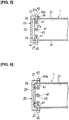
Figure 7] Figure 7 is a cross-sectional view that corresponds toFigure 5 , illustrating a second embodiment of the present invention. - [
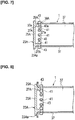
Figure 8] Figure 8 is an operation explanatory view illustrating an initial state in which the energy-absorbing member is crushed and deformed with respect toFigure 7 . - [
Figure 9] Figure 9 is a cross-sectional view of a state in which an energy-absorbing member is connected to a connecting member, illustrating a reference example of an energy-absorbing structure. - [
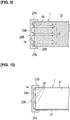
Figure 10] Figure 10 is a cross-sectional view of the energy-absorbing member and the connecting member at a position rotated 90°, with the load input direction as the axis, with respect toFigure 9 . - [
Figure 11] Figure 11 is a perspective view of the energy-absorbing member and the connecting member according to the reference example. - Embodiments for implementing the present invention are described in detail below with reference to the drawings.
-
Figure 1 illustrates the lower portion of a vehicle body equipped with energy-absorbingmembers 1 according to a first embodiment of the present invention. The energy-absorbingmembers 1 are a fiber-reinforced resin material formed by impregnating reinforcing fibers, for example carbon fibers, in a matrix resin that is a resin for impregnation. In the drawings, the direction indicated by the arrow FR is the front of the vehicle body, the direction indicated by the arrow LH is the left side of the vehicle body, and the direction indicated by the arrow UP is the up direction of the vehicle body. - In the automobile vehicle body shown in
Figure 1 , a pair of left and rightfront side members 3 are disposed on both sides of the front of the vehicle body in the vehicle width direction, along the longitudinal direction of the vehicle body. Thefront side members 3 each constitutes a frame member that forms the frame of the vehicle body and bends downward adjacent the location corresponding to the dash panel 5 and is joined to the lower surface of thefloor panel 7. The dash panel 5 separates thevehicle cabin 9 and theengine compartment 11.Side sills 13 are disposed on both sides of thefloor panel 7 in the vehicle width direction along the longitudinal direction of the vehicle body, and ahood ledge panels 15 are disposed on the upper portion of thefront side members 3 on the engine compartment side. - The energy-absorbing
members 1 are attached to the front-end portion of thefront side members 3. Abumper reinforcement 17 is attached to the front-end portion of the energy-absorbingmember 1 on the opposite side of thefront side members 3. Thebumper reinforcement 17 is disposed along the vehicle width direction, and both ends thereof project farther outwardly in the vehicle width direction than the energy-absorbingmember 1. A bumper fascia, not shown, is attached to thebumper reinforcement 17. - The
front side members 3 are formed in the shape of a quadrangular prism, and includes a front-end flange 3f at the front-end portion on the energy-absorbingmember 1 side, as illustrated inFigure 2 . A rear-end flange 1f is provided on the rear-end portion of the energy-absorbingmember 1 on the side with thefront side members 3. Thefront side members 3 and the energy-absorbingmembers 1 are fixed by causing the front-end flange 3f and the rear-end flange 1f to abut against each other and fastening them with a plurality ofnuts 21 and a plurality ofbolts 19. - The energy-absorbing
members 1 and thebumper reinforcement 17 are fixed via connectingmembers 23, as illustrated inFigures 2 and3 . Thebumper reinforcement 17 and the connectingmembers 23 constitute a load-receiving member. The energy-absorbingmembers 1 each have the shape of a quadrangular prism tube, in the same manner as thefront side members 3, as illustrated inFigure 3 . On the other hand, the connectingmembers 23 have a quadrangular shape that is larger than the energy-absorbingmembers 1 in a front view as seen from the front of the vehicle body. - The connecting
members 23 include anend surface portion 25 that abuts the rear surface of thebumper reinforcement 17, andside wall portions 27 that are bent from the four peripheral edges of theend surface portion 25 and that project toward the energy-absorbingmember 1. The inner side of the bent portion between theend surface portion 25 and theside wall portions 27 forms a concavecurved surface portion 29 over the entire perimeter, as illustrated inFigure 2 . - The
bumper reinforcement 17 is a hollow member whose cross-sectional shape is long vertically and has apartition wall 31 in the center in the vertical direction, and spaces having a cross section that is essentially square are formed above and below thepartition wall 31. Four through-holes 17a are provided on the rear surface of thebumper reinforcement 17, andstud bolts 33 are provided on theend surface portion 25 of the connectingmembers 23 corresponding to the through-holes 17a. Thebumper reinforcement 17 and the connectingmembers 23 are fixed and integrated by inserting thestud bolts 33 into the through-holes 17a, and fasteningnuts 35 to thestud bolts 33 by utilizingworking holes 17b on the front surface. - When the connecting
members 23 are fastened to the energy-absorbingmembers 1, the fourside wall portions 27 in the periphery of the connectingmembers 23 are attached, so as to cover the peripheral edges of the front-end portion of the energy-absorbingmembers 1 from the outside. At that time, the side-wall portions 27 of the connectingmembers 23 overlap theside surfaces 37 as the surface portions of the energy-absorbingmembers 1 from the outer side adjacent the front-end portion to form overlappingportions 39, as illustrated inFigure 2 . In the overlappingportions 39, the side-wall portions 27 of the connectingmembers 23 and theside surfaces 37 of the energy-absorbingmembers 1 overlap in an orthogonal direction that intersects the input direction of the impact load, which is described below. - A plurality of
bolt insertion holes 37a are formed that extend through theside surfaces 37 of the energy-absorbingmembers 1 in the overlappingportions 39, andnuts 41 are attached on the inner sides of theside surfaces 37 in the periphery of thebolt insertion holes 37a.Bolt insertion holes 27a are formed that pass through theside wall portions 27 of the connectingmembers 23 corresponding to thebolt insertion holes 37a. - The connecting
members 23 and the energy-absorbingmembers 1 are fixed by insertingbolts 43 as fasteners into thebolt insertion holes nuts 41, as illustrated inFigure 2 . Thebolt insertion holes portions 39. - In a state in which the connecting
members 23 and the energy-absorbingmembers 1 are fixed, a gap is formed betweenperipheral front ends 1a of the energy-absorbingmembers 1 and theend surface portions 25 of the connectingmembers 23, as illustrated inFigure 2 . At that time, thecurved surface portions 29 of the connectingmembers 23 are positioned in front of theperipheral front ends 1a of the energy-absorbingmembers 1, and theperipheral front ends 1a and thecurved surface portions 29 face each other. Thecurved surface portions 29 each have a cross section in the form of a quarter arc of a circle. The outer surfaces of the side surfaces 37 of the energy-absorbingmembers 1 are essentially positioned on a line tangent to the end portion of the arc. - Described next is the impact absorption function of when a vehicle provided with the energy-absorbing structure described above undergoes a front-end collision.
- The impact load that is received by the
bumper reinforcement 17 when the automobile undergoes a front-end collision is transmitted to the energy-absorbingmembers 1 via the connectingmembers 23. At this time, the energy-absorbingmembers 1 are crushed and deformed between thebumper reinforcement 17 and thefront side members 3, thereby absorbing the impact. When the energy-absorbingmembers 1 are crushed and deformed, the impact load is applied to the energy-absorbingmembers 1 via the fastening portion configured by thebolts 43 of the overlappingportions 39. - The
shaft portions 43a of thebolts 43 are inserted into thebolt insertion holes shaft portions 43a of thebolts 43 concentrate the stress in thebolt insertion holes 37a with respect to the energy-absorbingmembers 1 and becomes the point of origin when the energy-absorbingmembers 1 is crushed. Thebolts 43 are provided in two or three locations on oneside surface 37 of the energy-absorbingmembers 1. - Thus, the impact load that is concentrated at and imparted to the
bolt insertion holes 37a, as illustrated inFigure 4 , reaches the side surfaces 37 of the energy-absorbingmembers 1 for each of the plurality of thebolt insertion holes 37a, as indicated by the arrows P. The energy-absorbingmembers 1 are crushed and torn into multiple pieces along the load input direction with thebolt insertion holes 37a as the points of origin, due to the impact load that is imparted to each of the plurality of thebolt insertion holes 37a. That is, thebolts 43 are provided adjacent the end portion of the energy-absorbingmembers 1 and function as a tearing element that tears the energy-absorbingmembers 1 along the load input direction. - When the energy-absorbing
members 1 are crushed, the connectingmembers 23 moves in the direction toward thefront side members 3 and transitions from the state before the impact load is received shown inFigure 5 to the state shown inFigure 6 , so as to crush the energy-absorbingmembers 1. At this time, the energy-absorbingmembers 1 absorb the impact by the inward displacement of the peripheralfront ends 1a while being guided by thecurved surface portions 29 of the connectingmembers 23 over the entire perimeter. InFigures 5 and 6 ,stud bolts 33 that are similar to those of the connectingmembers 23 inFigure 3 are omitted. - In the energy-absorbing
members 1, reinforcingfibers 47 indicated by the chain double-dashed lines are arranged so as to extend in a direction that intersects the load input direction, which is essentially the same direction as that indicated by the arrows P, at, for example, an approximately 45° angle, as illustrated inFigure 4 . In this case, when the energy-absorbingmember 1 is torn by thebolts 43 and absorbs the impact load, the reinforcingfibers 47 are also severed, thereby absorbing the impact load. As a result, the energy absorption efficiency of the energy-absorbingmembers 1 is increased. InFigure 4 andFigure 11 , which is described below, only a portion of the reinforcingfibers 47 is shown, but in fact, the reinforcingfibers 47 are provided over the entirety of the energy-absorbingmembers 1. - In the present embodiment, a tearing element that tears the energy-absorbing
member 1 is composed of thebolts 43 that fasten and fix the energy-absorbingmember 1 and the connectingmember 23 on the side of thebumper reinforcement 17. Thus, it is not necessary to separately provide a tearing element, and it is possible to simplify the structure. - In the present embodiment, the energy-absorbing
members 1 have a tubular form, and theside wall portions 27 of the connectingmembers 23 are attached so as to cover the outer perimeter sides of the tubular energy-absorbingmembers 1 to form the overlappingportion 39. In this case as illustrated inFigure 6 , the energy-absorbingmembers 1 are crushed essentially uniformly over the entire perimeter between the connectingmembers 23 and the energy-absorbing members, by being displaced inwardly so as to be enveloped by theside wall portions 27 from the outside at the time of collapse, further enhancing the energy absorption efficiency. In addition, it is possible to prevent scattering to the outside by the inward displacement and crushing of the energy-absorbingmembers 1. - At this time, the inner side of the bent portion between the
end surface portions 25 and theside wall portions 27 of the connectingmembers 23 forms a concavecurved surface portions 29. Thus, the energy-absorbingmembers 1 absorb the impact load more efficiently by the peripheral front ends 1a being smoothly displaced inwardly while being guided by thecurved surface portions 29 of the connectingmembers 23. - In the present embodiment the energy-absorbing
members 1 have a prismatic tubular shape, and thebolts 43 that constitute the tearing element are provided at corresponding positions on the side surfaces 37 of the energy-absorbingmembers 1 formed in a prismatic tubular shape. As a result, stress can be concentrated not only at the corners of the prismatic tube where stress tends to concentrate but also on the side surfaces 37, which are surface portions, thereby tearing and crushing not only the corners but also the side surfaces 37. As a result, the tubular energy-absorbingmembers 1 are crushed essentially uniformly over the entire perimeter, and the energy absorption efficiency becomes extremely high. -
Figures 7 and 8 illustrate a second embodiment of the present invention. In the second embodiment, the shape of the connectingmember 23A is different from the connectingmembers 23 of the first embodiment, as illustrated inFigure 7 . The other configurations such as the energy-absorbingmembers 1 are the same as those of the first embodiment, and the same components have been assigned the same reference symbols, and detailed descriptions thereof have been omitted. - In the connecting
member 23A, theside wall portions 27A are positioned farther inward than the outer peripheral edge of theend surface portion 25A. Thus, theend surface portion 25A has a projecting portion 23Aa whose outer peripheral edge projects outwardly with respect to theside wall portions 27A over the entire perimeter. The outer side of the bent portion between theside wall portions 27A and the projecting portion 23Aa forms a concavecurved surface portion 29A over the entire perimeter. InFigures 7 and 8 ,stud bolts 33 that are similar to those of the connectingmember 23 inFigure 3 are omitted. - By positioning the
side wall portions 27A farther inward than the outer peripheral edge of theend surface portion 25A, the quadrangularside wall portions 27A will be inserted inside the energy-absorbingmember 1. That is, unlike the first embodiment, in the present embodiment, theside wall portions 27A of the connectingmember 23A are overlapped by the side surfaces 37 of the energy-absorbingmember 1 from the outside adjacent the front-end portion to form an overlappingportion 39A. - At this time the
curved surface portion 29A of the connectingmember 23A is positioned in front of the peripheralfront end 1a of the energy-absorbingmember 1, and the peripheralfront end 1a and thecurved surface portion 29A face each other. Thecurved surface portion 29A has a cross section in the form of a quarter arc of a circle. The inner surface of the side surfaces 37 of the energy-absorbingmember 1 is essentially positioned on a line tangent to the end portion of the arc. - Bolt insertion holes 27Aa are formed to pass through the
side wall portions 27A of the connectingmember 23A, corresponding to thebolt insertion holes 37a of the energy-absorbingmember 1.Nuts 41 are fixed on the inner sides of the periphery of the bolt insertion holes 27Aa. The connectingmember 23A and the energy-absorbingmember 1 are fixed by insertingbolts 43 into thebolt insertion holes 37a, 27Aa and fastening the nuts 41 on the bolts. - In the second embodiment as well, the impact load that is received by the
bumper reinforcement 17 is transmitted to the energy-absorbingmember 1 via the connectingmember 23A in the state shown inFigure 7 . At that time, the energy-absorbingmember 1 is crushed and deformed between thebumper reinforcement 17 and thefront side members 3 to absorb the impact. - When the energy-absorbing
member 1 is crushed and deformed, the impact load is input to the energy-absorbingmember 1 via the fastening portion configured by thebolts 43 of the overlappingportion 39A. Theshaft portions 43a of thebolts 43 are inserted into the bolt insertion holes 27Aa, 37a. Thus, theshaft portion 43a of thebolt 43 concentrates the stress in thebolt insertion hole 37a and becomes the point of origin when the energy-absorbingmember 1 is crushed. - Because in the second embodiment, a plurality of
bolts 43 are also provided in the same positions as in the first embodiment, as inFigure 4 , the impact load that is imparted to abolt insertion hole 37a reaches theside surface 37 of the energy-absorbingmember 1 for each of the plurality ofbolt insertion holes 37a, as indicated by the arrows P. The energy-absorbingmember 1 is crushed so as to be torn into multiple pieces along the load input direction with thebolt insertion holes 37a as the points of origin, due to the impact load that is imparted to each of the plurality ofbolt insertion holes 37a. That is, theshaft portion 43a of thebolt 43 functions as a tearing element that tears the energy-absorbingmember 1. - At this time, in the second embodiment, the energy-absorbing
member 1 is positioned on the outer side of theside wall portions 27A of the connectingmember 23A. Thus, the connectingmember 23A moves in the direction toward thefront side members 3 and transitions from the state before the impact load is received, as shown inFigure 7 to the state shown inFigure 8 , thereby crushing the energy-absorbingmember 1. At this time, the energy-absorbingmember 1 efficiently absorbs the impact by the outward displacement of the peripheralfront end 1a while being guided by thecurved surface portion 29A of the connectingmember 23A over the entire perimeter. - In the second embodiment as well, in the energy-absorbing
member 1, reinforcingfibers 47 indicated by the chain double-dashed lines are arranged in a direction that intersects the load input direction, which is essentially the same direction as that indicated by the arrows P, at, for example, an approximately 45° angle, as illustrated inFigure 4 . In this case, when the energy-absorbingmember 1 is torn by thebolts 43 and absorbs the impact load, the reinforcingfibers 47 are also severed, thereby absorbing the impact load. As a result, the energy absorption efficiency of the energy-absorbingmember 1 is increased. -
Figures 9-11 illustrate a reference example of an energy-absorbing structure. In the reference example, the shape of the connectingmember 23B is different from the connectingmember 23 of the first embodiment. The other configurations such as the energy-absorbingmember 1 are the same as those of the first embodiment, and the same components have been assigned the same reference symbols, and the detailed descriptions thereof have been omitted. - The connecting
member 23B is provided with a plurality ofprojections 49 as a tearing element that projects toward the energy-absorbingmember 1 on the inner side of theend surface portion 25B. The distal ends of theprojections 49 have curved convex surfaces. Bolt insertion holes are not provided on theside wall portions 27B. InFigures 9-11 ,stud bolts 33 that are similar to those of the connectingmember 23 inFigure 3 are omitted. - The
projections 49 are positioned at the inner corners between theend surface portion 25B and theside wall portions 27B, and the distal ends of the curved convex surfaces described above abut the peripheralfront end 1a of the energy-absorbingmember 1. Theprojections 49 are provided at two or three locations on oneside surface 37 of the energy-absorbingmember 1. The circumferential positions of the plurality ofprojections 49 with respect to the energy-absorbingmember 1 are essentially the same as the positions of the plurality ofbolt insertion holes 37a of the first embodiment. - In the state in which the front-end portion of the energy-absorbing
member 1 is inserted into the inner side of theside wall portions 27B of the connectingmember 23B, the peripheralfront end 1a abuts theprojections 49, and the outer circumferential surface is essentially in close contact with the inner surfaces of theside wall portions 27B. In this state, theside wall portions 27B and the energy-absorbingmember 1 are bonded and fixed by using, for example, an adhesive. - In the reference example the
projections 49 act as a tearing element instead of thebolts 43 in the first and second embodiments. Thus, the impact load that is received by the connectingmember 23B will be in a state in which stress is concentrated at the peripheralfront end 1a due to the plurality ofprojections 49, as illustrated inFigure 11 . Thus, the impact load reaches the side surfaces 37 of the energy-absorbingmember 1 for each of the plurality ofprojections 49, as indicated by the arrows P. As a result, the energy-absorbingmember 1 is torn into multiple pieces along the load input direction with theprojections 49 as the points of origin. That is, theprojections 49 function as a tearing element that tears the energy-absorbingmember 1. - At this time the connecting
member 23B moves in the direction toward thefront side members 3 and transitions from the state before the impact load is received shown inFigure 9 , so as to crush the energy-absorbingmember 1. At this time, the energy-absorbingmember 1 absorbs the impact by being inwardly displaced as it tears. - In the reference example as well, in the energy-absorbing
member 1, reinforcingfibers 47 indicated by the chain double-dashed lines are arranged in a direction that intersects the load input direction, which is essentially the same direction as that indicated by the arrows P, at an approximately 45° angle, for example, as illustrated inFigure 11 . In this case, when the energy-absorbingmember 1 is torn by theprojections 49 and absorbs the impact load, the reinforcingfibers 47 are also severed, thereby absorbing the impact load. As a result, the energy absorption efficiency of the energy-absorbingmember 1 is increased. - In addition, in the reference example, as in the first embodiment, the
side wall portions 27B of the connectingmember 23B are attached so as to cover the outer perimeter side of the energy-absorbingmember 1. Thus, the energy-absorbingmember 1 is crushed essentially uniformly over the entire perimeter between the connectingmember 23B and the energy-absorbing member, by being displaced inwardly so as to be enveloped by theside wall portions 27B from the outer side at the time of collapse, further enhancing the energy absorption efficiency. Furthermore, it is possible to prevent scattering to the outside by the inward displacement and crushing of the energy-absorbingmember 1. - In the reference example,
projections 49 that are integral with the connectingmember 23B are provided as the tearing element, instead of thebolts 43 that are used in the first and second embodiments. Thus,numerous bolts 43, etc., become unnecessary, which correspondingly reduces the parts count and improves the assembly workability. Although the connectingmember 23B and the energy-absorbingmember 1 are fixed by means of an adhesive, for example, four appropriate peripheral locations may be fixed using bolts and nuts. - The reference example may also be configured such that the
side wall portions 27B of the connectingmember 23B are inserted into the inner side of the energy-absorbingmember 1, in the same manner as shown inFigure 7 of the second embodiment. In this case, projections that abut the peripheralfront end 1a are provided in a portion corresponding to the projecting portions 23Aa ofFigure 7 , in front of the peripheralfront end 1a of the energy-absorbingmember 1. - Embodiments of the present invention were described above, but these embodiments are described in order to facilitate comprehension of the present invention, and the present invention is not limited to the embodiments described. The technical scope of the present invention is not limited to the specific technical matters disclosed in the above-described embodiment and includes various modifications, changes, and alternatives that can be easily derived therefrom.
- For example, in the embodiments described above, examples were shown in which an energy-absorbing structure including an energy-absorbing
member 1 is provided in the front of the vehicle body, but a similar effect can also be achieved by providing the energy-absorbing structure in the rear of the vehicle body. - In the embodiments described above, the tearing element, constituted by the
bolts 43 in the first and second embodiments or theprojections 49 in the reference example, is provided on thebumper reinforcement 17 side of the energy-absorbingmember 1. Alternatively, the tearing element can be provided on the side of the energy-absorbingmember 1 adjacent thefront side members 3, or provided on both the side of thebumper reinforcement 17 and the side of thefront side members 3. - In the case of providing the tearing element only on the side of the
front side members 3 of the energy-absorbingmember 1, the front and rear of the energy-absorbingmember 1 shown inFigures 2 and3 are reversed, and therear end flange 1f is fixed on the rear surface of thebumper reinforcement 17. In the connectingmember 23, thestud bolts 33 are set in positions corresponding to thebolts 19 inFigure 2 and made to abut the front-end flange 3f of thefront side members 3, and the nuts 21 are fastened to thestud bolts 33. - In the case of providing the tearing element on both the
bumper reinforcement 17 side and thefront side members 3 side of the energy-absorbingmember 1, the energy-absorbingmember 1 is not provided with therear end flange 1f as shown inFigures 2 and3 , and the shapes of both the front and rear end portions are made the same. In this case, the attachment structure of the rear end portion of the energy-absorbingmember 1 with respect to thefront side members 3 is the same as when the tearing element described above is only provided on the side of thefront side members 3 of the energy-absorbingmember 1. - In the embodiments described above, the energy-absorbing
member 1 is configured to have the form of a quadrangular prism tube, but the shape may be a polygonal shape or a columnar tube shape, other than the form of a quadrangular prism. In this case, the shapes of the connectingmembers member 1. - In the energy-absorbing
member 1 of the embodiments described above, examples were shown in which reinforcingfibers 47 are arranged in a direction that intersects the load input direction, at an angle of approximately 45°, which is essentially the same direction as that indicated by the arrows P, as illustrated inFigures 4 and11 . However, the angle of intersection is not limited to 45°. The reinforcingfibers 47 may intersect the load input direction at a 90° angle, for example. In other words, the reinforcingfibers 47 need only intersect the load input direction in essentially the same direction as that indicated by the arrows P. Because the reinforcingfibers 47 cross the load input direction, the reinforcing fibers are severed by the tearing element. - Also, the first embodiment, which employs
bolts 43, and the reference example, which employsprojections 49, can be combined. In this case, for example, by shifting the positions along the perimeter direction, such as alternately arranging thebolts 43 and theprojections 49 along the perimeter direction, thebolts 43 and theprojections 49 are prevented from overlapping along the load input direction. Thebolts 43 in the second embodiment shown inFigure 7 and the projections that are provided in front of the peripheralfront end 1a of the energy-absorbingmember 1 can be combined as well. - The present invention is applied to an energy-absorbing structure that uses an energy-absorbing member made of fiber-reinforced resin.
-
- 1
- Energy-absorbing member
- 3
- Front side member (frame member)
- 17
- Bumper reinforcement (load-receiving member)
- 23, 23A, 23B
- Connecting member (load-receiving member)
- 27a, 27Aa, 37a
- Bolt insertion hole (mounting hole)
- 37
- Side surface of energy-absorbing member (surface portion)
- 39, 39A
- Overlapping portion
- 43
- Bolt (fastener, tearing element)
- 47
- Reinforcing fiber
- 49
- Projection (tearing element)
Claims (5)
- An energy-absorbing structure comprising:a frame member (3) forming a part of a vehicle body framework;an energy-absorbing member (1) formed from fiber-reinforced resin and provided at an end portion of the frame member;a load-receiving member (17, 23) provided on the energy-absorbing member on a side opposite of the frame member; anda tearing element (43, 49) provided adjacent an end portion of the energy-absorbing member that corresponds to at least one of the load-receiving member and the frame member so as to tear the energy-absorbing member upon an impact load being inputted from the load-receiving member toward the energy-absorbing member, whereinreinforcing fibers (47) that extend in a direction intersecting an input direction of the impact load in the energy-absorbing member, and that are severed by the tearing element upon the energy-absorbing member being torn,characterized in that:the load-receiving member and the energy-absorbing member overlap in a direction that intersects with the input direction of the impact load to form an overlapping portion (39);the overlapping portion has a mounting hole (27) that extends in a direction of the overlap; andthe tearing element is constituted by a fastener (43) inserted into the mounting hole.
- The energy-absorbing structure as recited in claim 1, wherein
the energy-absorbing member (1) has a tubular shape, and
at least one of the load-receiving member (17, 23) and the frame member (3) is attached to overlie an outer perimeter side of the tubular shape of the energy-absorbing member to form the overlapping portion (39). - The energy-absorbing structure as recited in claim 1 or 2, wherein
at least one of the load-receiving member (17, 23) and the frame member (3) includes a portion having a curved concave surface that opposes the end portion of the energy-absorbing member (1) on which the tearing element (43, 49) is provided. - The energy-absorbing structure as recited in any one of claims 1 to 3, wherein
the tearing element (43, 49) includes
a projection (49) that projects toward the energy-absorbing member (1) in a portion of at least one of the load-receiving member (17, 23) and the frame member (3) that opposes the energy-absorbing member. - The energy-absorbing structure recited in any one of claims 1 to 4, wherein
the energy-absorbing member (1) has a prismatic tubular shape, and
the tearing element (43, 49) is disposed in a position that corresponds to a surface portion (37) of the prismatic tubular shape.
Applications Claiming Priority (1)
| Application Number | Priority Date | Filing Date | Title |
|---|---|---|---|
| PCT/JP2016/062095 WO2017179187A1 (en) | 2016-04-15 | 2016-04-15 | Energy absorption structure |
Publications (3)
| Publication Number | Publication Date |
|---|---|
| EP3444146A4 EP3444146A4 (en) | 2019-02-20 |
| EP3444146A1 EP3444146A1 (en) | 2019-02-20 |
| EP3444146B1 true EP3444146B1 (en) | 2020-04-08 |
Family
ID=60041520
Family Applications (1)
| Application Number | Title | Priority Date | Filing Date |
|---|---|---|---|
| EP16898647.9A Active EP3444146B1 (en) | 2016-04-15 | 2016-04-15 | Energy absorption structure |
Country Status (5)
| Country | Link |
|---|---|
| US (1) | US10710532B2 (en) |
| EP (1) | EP3444146B1 (en) |
| JP (1) | JP6569804B2 (en) |
| CN (1) | CN109070820B (en) |
| WO (1) | WO2017179187A1 (en) |
Families Citing this family (2)
| Publication number | Priority date | Publication date | Assignee | Title |
|---|---|---|---|---|
| JP6581686B1 (en) * | 2018-03-30 | 2019-09-25 | 株式会社Uacj | Bumper structure |
| JP7065689B2 (en) * | 2018-05-24 | 2022-05-12 | 三菱重工業株式会社 | Impact absorbing member and shock absorber |
Family Cites Families (16)
| Publication number | Priority date | Publication date | Assignee | Title |
|---|---|---|---|---|
| JP3144054B2 (en) * | 1992-05-28 | 2001-03-07 | 株式会社豊田自動織機製作所 | Energy absorbing material |
| DE4425829C1 (en) * | 1994-07-21 | 1995-10-12 | Daimler Benz Aerospace Ag | Helicopter structural element in sandwich form |
| DE19623449A1 (en) * | 1996-06-12 | 1998-01-02 | Daimler Benz Ag | Tube for motor vehicles used in absorption of impact energy in event of collision |
| US5914163A (en) * | 1997-10-10 | 1999-06-22 | General Motors Corporation | Reduced crush initiation force composite tube |
| US6601886B1 (en) | 2002-05-31 | 2003-08-05 | Hexcel Corporation | Energy absorbing composite tube |
| DE10243460A1 (en) * | 2002-09-19 | 2004-04-01 | Rehau Ag + Co. | Polymer energy absorber for motor vehicles and bumper system |
| NO20032896D0 (en) * | 2003-06-23 | 2003-06-23 | Norsk Hydro As | Energy absorbing system |
| JP2005247096A (en) * | 2004-03-03 | 2005-09-15 | Nippon Gmt Kk | Vehicular impact absorbing body and vehicular impact absorbing device |
| JP4440683B2 (en) | 2004-03-26 | 2010-03-24 | 日産自動車株式会社 | Mounting structure of fiber reinforced plastic energy absorbing member |
| EP2511141B1 (en) * | 2011-04-13 | 2014-01-22 | Volvo Car Corporation | Collision energy absorbing device and a method for controlling energy imparted to a vehicle during a collision |
| DE102012200410A1 (en) * | 2012-01-12 | 2013-07-18 | Thermoplast Composite Gmbh | Energy-absorbing support structure and method for producing this |
| DE102012214751A1 (en) * | 2012-08-20 | 2014-06-05 | Bayerische Motoren Werke Aktiengesellschaft | vehicle |
| WO2014042211A1 (en) * | 2012-09-13 | 2014-03-20 | 本田技研工業株式会社 | Structure for front part of body of automobile |
| DE102013200678A1 (en) * | 2013-01-17 | 2014-07-17 | Bayerische Motoren Werke Aktiengesellschaft | Energy absorption structure for a vehicle |
| JP2015085788A (en) * | 2013-10-30 | 2015-05-07 | いすゞ自動車株式会社 | Support structure for specified component of vehicle |
| CN104691467B (en) * | 2015-01-06 | 2016-11-02 | 华侨大学 | Collision composite endergonic device and purposes |
-
2016
- 2016-04-15 CN CN201680084637.0A patent/CN109070820B/en active Active
- 2016-04-15 JP JP2018511849A patent/JP6569804B2/en active Active
- 2016-04-15 WO PCT/JP2016/062095 patent/WO2017179187A1/en active Application Filing
- 2016-04-15 US US16/093,159 patent/US10710532B2/en active Active
- 2016-04-15 EP EP16898647.9A patent/EP3444146B1/en active Active
Non-Patent Citations (1)
| Title |
|---|
| None * |
Also Published As
| Publication number | Publication date |
|---|---|
| JP6569804B2 (en) | 2019-09-04 |
| EP3444146A4 (en) | 2019-02-20 |
| US20190135210A1 (en) | 2019-05-09 |
| CN109070820A (en) | 2018-12-21 |
| JPWO2017179187A1 (en) | 2019-02-21 |
| CN109070820B (en) | 2021-07-06 |
| US10710532B2 (en) | 2020-07-14 |
| EP3444146A1 (en) | 2019-02-20 |
| WO2017179187A1 (en) | 2017-10-19 |
Similar Documents
| Publication | Publication Date | Title |
|---|---|---|
| JP6449562B2 (en) | Vehicle frame structure | |
| EP3604044B1 (en) | Impact absorption member for vehicles | |
| EP2076421B1 (en) | Vehicle front structure | |
| JP5696793B2 (en) | Body structure | |
| EP3079972B1 (en) | Vehicle front structure | |
| JP5954312B2 (en) | Vehicle front structure | |
| EP3009307A1 (en) | Vehicle body front part structure | |
| JP6562064B2 (en) | Vehicle shock absorption structure | |
| JP6136187B2 (en) | Battery mounting structure for vehicles | |
| JP5862555B2 (en) | Auto body structure | |
| JP2015209111A (en) | Vehicle front structure | |
| JP6070481B2 (en) | Junction structure | |
| EP3444146B1 (en) | Energy absorption structure | |
| JP6102817B2 (en) | Vehicle rear structure | |
| EP3446929A1 (en) | Energy absorbing structure | |
| JP4973045B2 (en) | Vehicle front structure | |
| JP6520694B2 (en) | Vehicle front structure | |
| JP2008189232A (en) | Vehicle front part structure | |
| WO2020149308A1 (en) | Automobile side structure and automobile | |
| JP2018176889A (en) | Bumper reinforcement | |
| JP6566018B2 (en) | Vehicle shock absorption structure | |
| WO2014097765A1 (en) | Automobile body structure | |
| JP6112002B2 (en) | Vehicle cowl side structure | |
| JP4440683B2 (en) | Mounting structure of fiber reinforced plastic energy absorbing member | |
| KR20200065487A (en) | Bumper back bean of vehicle |
Legal Events
| Date | Code | Title | Description |
|---|---|---|---|
| STAA | Information on the status of an ep patent application or granted ep patent |
Free format text: STATUS: THE INTERNATIONAL PUBLICATION HAS BEEN MADE |
|
| PUAI | Public reference made under article 153(3) epc to a published international application that has entered the european phase |
Free format text: ORIGINAL CODE: 0009012 |
|
| STAA | Information on the status of an ep patent application or granted ep patent |
Free format text: STATUS: REQUEST FOR EXAMINATION WAS MADE |
|
| 17P | Request for examination filed |
Effective date: 20181113 |
|
| A4 | Supplementary search report drawn up and despatched |
Effective date: 20181217 |
|
| AK | Designated contracting states |
Kind code of ref document: A1 Designated state(s): AL AT BE BG CH CY CZ DE DK EE ES FI FR GB GR HR HU IE IS IT LI LT LU LV MC MK MT NL NO PL PT RO RS SE SI SK SM TR |
|
| AX | Request for extension of the european patent |
Extension state: BA ME |
|
| DAV | Request for validation of the european patent (deleted) | ||
| DAX | Request for extension of the european patent (deleted) | ||
| GRAP | Despatch of communication of intention to grant a patent |
Free format text: ORIGINAL CODE: EPIDOSNIGR1 |
|
| STAA | Information on the status of an ep patent application or granted ep patent |
Free format text: STATUS: GRANT OF PATENT IS INTENDED |
|
| INTG | Intention to grant announced |
Effective date: 20191022 |
|
| GRAS | Grant fee paid |
Free format text: ORIGINAL CODE: EPIDOSNIGR3 |
|
| GRAA | (expected) grant |
Free format text: ORIGINAL CODE: 0009210 |
|
| STAA | Information on the status of an ep patent application or granted ep patent |
Free format text: STATUS: THE PATENT HAS BEEN GRANTED |
|
| AK | Designated contracting states |
Kind code of ref document: B1 Designated state(s): AL AT BE BG CH CY CZ DE DK EE ES FI FR GB GR HR HU IE IS IT LI LT LU LV MC MK MT NL NO PL PT RO RS SE SI SK SM TR |
|
| RAP1 | Party data changed (applicant data changed or rights of an application transferred) |
Owner name: RENAULT S.A.S. Owner name: NISSAN MOTOR CO., LTD. |
|
| REG | Reference to a national code |
Ref country code: CH Ref legal event code: EP Ref country code: AT Ref legal event code: REF Ref document number: 1253961 Country of ref document: AT Kind code of ref document: T Effective date: 20200415 |
|
| REG | Reference to a national code |
Ref country code: DE Ref legal event code: R096 Ref document number: 602016033887 Country of ref document: DE |
|
| REG | Reference to a national code |
Ref country code: IE Ref legal event code: FG4D |
|
| REG | Reference to a national code |
Ref country code: NL Ref legal event code: MP Effective date: 20200408 |
|
| REG | Reference to a national code |
Ref country code: LT Ref legal event code: MG4D |
|
| PG25 | Lapsed in a contracting state [announced via postgrant information from national office to epo] |
Ref country code: NL Free format text: LAPSE BECAUSE OF FAILURE TO SUBMIT A TRANSLATION OF THE DESCRIPTION OR TO PAY THE FEE WITHIN THE PRESCRIBED TIME-LIMIT Effective date: 20200408 Ref country code: SE Free format text: LAPSE BECAUSE OF FAILURE TO SUBMIT A TRANSLATION OF THE DESCRIPTION OR TO PAY THE FEE WITHIN THE PRESCRIBED TIME-LIMIT Effective date: 20200408 Ref country code: FI Free format text: LAPSE BECAUSE OF FAILURE TO SUBMIT A TRANSLATION OF THE DESCRIPTION OR TO PAY THE FEE WITHIN THE PRESCRIBED TIME-LIMIT Effective date: 20200408 Ref country code: GR Free format text: LAPSE BECAUSE OF FAILURE TO SUBMIT A TRANSLATION OF THE DESCRIPTION OR TO PAY THE FEE WITHIN THE PRESCRIBED TIME-LIMIT Effective date: 20200709 Ref country code: NO Free format text: LAPSE BECAUSE OF FAILURE TO SUBMIT A TRANSLATION OF THE DESCRIPTION OR TO PAY THE FEE WITHIN THE PRESCRIBED TIME-LIMIT Effective date: 20200708 Ref country code: IS Free format text: LAPSE BECAUSE OF FAILURE TO SUBMIT A TRANSLATION OF THE DESCRIPTION OR TO PAY THE FEE WITHIN THE PRESCRIBED TIME-LIMIT Effective date: 20200808 Ref country code: LT Free format text: LAPSE BECAUSE OF FAILURE TO SUBMIT A TRANSLATION OF THE DESCRIPTION OR TO PAY THE FEE WITHIN THE PRESCRIBED TIME-LIMIT Effective date: 20200408 Ref country code: PT Free format text: LAPSE BECAUSE OF FAILURE TO SUBMIT A TRANSLATION OF THE DESCRIPTION OR TO PAY THE FEE WITHIN THE PRESCRIBED TIME-LIMIT Effective date: 20200817 |
|
| REG | Reference to a national code |
Ref country code: AT Ref legal event code: MK05 Ref document number: 1253961 Country of ref document: AT Kind code of ref document: T Effective date: 20200408 |
|
| PG25 | Lapsed in a contracting state [announced via postgrant information from national office to epo] |
Ref country code: LV Free format text: LAPSE BECAUSE OF FAILURE TO SUBMIT A TRANSLATION OF THE DESCRIPTION OR TO PAY THE FEE WITHIN THE PRESCRIBED TIME-LIMIT Effective date: 20200408 Ref country code: RS Free format text: LAPSE BECAUSE OF FAILURE TO SUBMIT A TRANSLATION OF THE DESCRIPTION OR TO PAY THE FEE WITHIN THE PRESCRIBED TIME-LIMIT Effective date: 20200408 Ref country code: BG Free format text: LAPSE BECAUSE OF FAILURE TO SUBMIT A TRANSLATION OF THE DESCRIPTION OR TO PAY THE FEE WITHIN THE PRESCRIBED TIME-LIMIT Effective date: 20200708 Ref country code: HR Free format text: LAPSE BECAUSE OF FAILURE TO SUBMIT A TRANSLATION OF THE DESCRIPTION OR TO PAY THE FEE WITHIN THE PRESCRIBED TIME-LIMIT Effective date: 20200408 |
|
| REG | Reference to a national code |
Ref country code: CH Ref legal event code: PL |
|
| PG25 | Lapsed in a contracting state [announced via postgrant information from national office to epo] |
Ref country code: AL Free format text: LAPSE BECAUSE OF FAILURE TO SUBMIT A TRANSLATION OF THE DESCRIPTION OR TO PAY THE FEE WITHIN THE PRESCRIBED TIME-LIMIT Effective date: 20200408 |
|
| REG | Reference to a national code |
Ref country code: DE Ref legal event code: R097 Ref document number: 602016033887 Country of ref document: DE |
|
| PG25 | Lapsed in a contracting state [announced via postgrant information from national office to epo] |
Ref country code: RO Free format text: LAPSE BECAUSE OF FAILURE TO SUBMIT A TRANSLATION OF THE DESCRIPTION OR TO PAY THE FEE WITHIN THE PRESCRIBED TIME-LIMIT Effective date: 20200408 Ref country code: CZ Free format text: LAPSE BECAUSE OF FAILURE TO SUBMIT A TRANSLATION OF THE DESCRIPTION OR TO PAY THE FEE WITHIN THE PRESCRIBED TIME-LIMIT Effective date: 20200408 Ref country code: LU Free format text: LAPSE BECAUSE OF NON-PAYMENT OF DUE FEES Effective date: 20200415 Ref country code: DK Free format text: LAPSE BECAUSE OF FAILURE TO SUBMIT A TRANSLATION OF THE DESCRIPTION OR TO PAY THE FEE WITHIN THE PRESCRIBED TIME-LIMIT Effective date: 20200408 Ref country code: AT Free format text: LAPSE BECAUSE OF FAILURE TO SUBMIT A TRANSLATION OF THE DESCRIPTION OR TO PAY THE FEE WITHIN THE PRESCRIBED TIME-LIMIT Effective date: 20200408 Ref country code: IT Free format text: LAPSE BECAUSE OF FAILURE TO SUBMIT A TRANSLATION OF THE DESCRIPTION OR TO PAY THE FEE WITHIN THE PRESCRIBED TIME-LIMIT Effective date: 20200408 Ref country code: SM Free format text: LAPSE BECAUSE OF FAILURE TO SUBMIT A TRANSLATION OF THE DESCRIPTION OR TO PAY THE FEE WITHIN THE PRESCRIBED TIME-LIMIT Effective date: 20200408 Ref country code: EE Free format text: LAPSE BECAUSE OF FAILURE TO SUBMIT A TRANSLATION OF THE DESCRIPTION OR TO PAY THE FEE WITHIN THE PRESCRIBED TIME-LIMIT Effective date: 20200408 Ref country code: ES Free format text: LAPSE BECAUSE OF FAILURE TO SUBMIT A TRANSLATION OF THE DESCRIPTION OR TO PAY THE FEE WITHIN THE PRESCRIBED TIME-LIMIT Effective date: 20200408 Ref country code: LI Free format text: LAPSE BECAUSE OF NON-PAYMENT OF DUE FEES Effective date: 20200430 Ref country code: MC Free format text: LAPSE BECAUSE OF FAILURE TO SUBMIT A TRANSLATION OF THE DESCRIPTION OR TO PAY THE FEE WITHIN THE PRESCRIBED TIME-LIMIT Effective date: 20200408 Ref country code: CH Free format text: LAPSE BECAUSE OF NON-PAYMENT OF DUE FEES Effective date: 20200430 |
|
| REG | Reference to a national code |
Ref country code: BE Ref legal event code: MM Effective date: 20200430 |
|
| PLBE | No opposition filed within time limit |
Free format text: ORIGINAL CODE: 0009261 |
|
| STAA | Information on the status of an ep patent application or granted ep patent |
Free format text: STATUS: NO OPPOSITION FILED WITHIN TIME LIMIT |
|
| PG25 | Lapsed in a contracting state [announced via postgrant information from national office to epo] |
Ref country code: PL Free format text: LAPSE BECAUSE OF FAILURE TO SUBMIT A TRANSLATION OF THE DESCRIPTION OR TO PAY THE FEE WITHIN THE PRESCRIBED TIME-LIMIT Effective date: 20200408 Ref country code: SK Free format text: LAPSE BECAUSE OF FAILURE TO SUBMIT A TRANSLATION OF THE DESCRIPTION OR TO PAY THE FEE WITHIN THE PRESCRIBED TIME-LIMIT Effective date: 20200408 Ref country code: BE Free format text: LAPSE BECAUSE OF NON-PAYMENT OF DUE FEES Effective date: 20200430 |
|
| 26N | No opposition filed |
Effective date: 20210112 |
|
| PG25 | Lapsed in a contracting state [announced via postgrant information from national office to epo] |
Ref country code: IE Free format text: LAPSE BECAUSE OF NON-PAYMENT OF DUE FEES Effective date: 20200415 |
|
| PG25 | Lapsed in a contracting state [announced via postgrant information from national office to epo] |
Ref country code: SI Free format text: LAPSE BECAUSE OF FAILURE TO SUBMIT A TRANSLATION OF THE DESCRIPTION OR TO PAY THE FEE WITHIN THE PRESCRIBED TIME-LIMIT Effective date: 20200408 |
|
| PG25 | Lapsed in a contracting state [announced via postgrant information from national office to epo] |
Ref country code: TR Free format text: LAPSE BECAUSE OF FAILURE TO SUBMIT A TRANSLATION OF THE DESCRIPTION OR TO PAY THE FEE WITHIN THE PRESCRIBED TIME-LIMIT Effective date: 20200408 Ref country code: MT Free format text: LAPSE BECAUSE OF FAILURE TO SUBMIT A TRANSLATION OF THE DESCRIPTION OR TO PAY THE FEE WITHIN THE PRESCRIBED TIME-LIMIT Effective date: 20200408 Ref country code: CY Free format text: LAPSE BECAUSE OF FAILURE TO SUBMIT A TRANSLATION OF THE DESCRIPTION OR TO PAY THE FEE WITHIN THE PRESCRIBED TIME-LIMIT Effective date: 20200408 |
|
| PG25 | Lapsed in a contracting state [announced via postgrant information from national office to epo] |
Ref country code: MK Free format text: LAPSE BECAUSE OF FAILURE TO SUBMIT A TRANSLATION OF THE DESCRIPTION OR TO PAY THE FEE WITHIN THE PRESCRIBED TIME-LIMIT Effective date: 20200408 |
|
| PGFP | Annual fee paid to national office [announced via postgrant information from national office to epo] |
Ref country code: FR Payment date: 20230321 Year of fee payment: 8 |
|
| PGFP | Annual fee paid to national office [announced via postgrant information from national office to epo] |
Ref country code: GB Payment date: 20230321 Year of fee payment: 8 |
|
| PGFP | Annual fee paid to national office [announced via postgrant information from national office to epo] |
Ref country code: DE Payment date: 20230321 Year of fee payment: 8 |
|
| PGFP | Annual fee paid to national office [announced via postgrant information from national office to epo] |
Ref country code: GB Payment date: 20240321 Year of fee payment: 9 |