EP2511999A1 - Reconfigurable power converters, systems and plants - Google Patents
Reconfigurable power converters, systems and plants Download PDFInfo
- Publication number
- EP2511999A1 EP2511999A1 EP20120159377 EP12159377A EP2511999A1 EP 2511999 A1 EP2511999 A1 EP 2511999A1 EP 20120159377 EP20120159377 EP 20120159377 EP 12159377 A EP12159377 A EP 12159377A EP 2511999 A1 EP2511999 A1 EP 2511999A1
- Authority
- EP
- European Patent Office
- Prior art keywords
- power
- storage device
- converter
- electrical energy
- energy storage
- Prior art date
- Legal status (The legal status is an assumption and is not a legal conclusion. Google has not performed a legal analysis and makes no representation as to the accuracy of the status listed.)
- Granted
Links
- 238000004146 energy storage Methods 0.000 claims abstract description 149
- 230000008878 coupling Effects 0.000 claims description 44
- 238000010168 coupling process Methods 0.000 claims description 44
- 238000005859 coupling reaction Methods 0.000 claims description 44
- 238000003860 storage Methods 0.000 claims description 24
- 238000000034 method Methods 0.000 claims description 17
- 239000003990 capacitor Substances 0.000 claims description 16
- 239000004065 semiconductor Substances 0.000 claims description 7
- 238000011017 operating method Methods 0.000 abstract 1
- 238000010586 diagram Methods 0.000 description 14
- 230000006870 function Effects 0.000 description 13
- 238000010248 power generation Methods 0.000 description 7
- 238000007599 discharging Methods 0.000 description 2
- 230000003287 optical effect Effects 0.000 description 2
- 230000008901 benefit Effects 0.000 description 1
- 230000005540 biological transmission Effects 0.000 description 1
- 230000008859 change Effects 0.000 description 1
- 238000004590 computer program Methods 0.000 description 1
- 238000010348 incorporation Methods 0.000 description 1
- 238000004519 manufacturing process Methods 0.000 description 1
- 239000013307 optical fiber Substances 0.000 description 1
- 230000009467 reduction Effects 0.000 description 1
- 238000004513 sizing Methods 0.000 description 1
- 230000001052 transient effect Effects 0.000 description 1
- 230000007704 transition Effects 0.000 description 1
Images


Classifications
-
- H—ELECTRICITY
- H02—GENERATION; CONVERSION OR DISTRIBUTION OF ELECTRIC POWER
- H02J—CIRCUIT ARRANGEMENTS OR SYSTEMS FOR SUPPLYING OR DISTRIBUTING ELECTRIC POWER; SYSTEMS FOR STORING ELECTRIC ENERGY
- H02J3/00—Circuit arrangements for ac mains or ac distribution networks
- H02J3/28—Arrangements for balancing of the load in a network by storage of energy
- H02J3/32—Arrangements for balancing of the load in a network by storage of energy using batteries with converting means
-
- H—ELECTRICITY
- H02—GENERATION; CONVERSION OR DISTRIBUTION OF ELECTRIC POWER
- H02J—CIRCUIT ARRANGEMENTS OR SYSTEMS FOR SUPPLYING OR DISTRIBUTING ELECTRIC POWER; SYSTEMS FOR STORING ELECTRIC ENERGY
- H02J3/00—Circuit arrangements for ac mains or ac distribution networks
- H02J3/38—Arrangements for parallely feeding a single network by two or more generators, converters or transformers
- H02J3/381—Dispersed generators
-
- H—ELECTRICITY
- H02—GENERATION; CONVERSION OR DISTRIBUTION OF ELECTRIC POWER
- H02S—GENERATION OF ELECTRIC POWER BY CONVERSION OF INFRARED RADIATION, VISIBLE LIGHT OR ULTRAVIOLET LIGHT, e.g. USING PHOTOVOLTAIC [PV] MODULES
- H02S40/00—Components or accessories in combination with PV modules, not provided for in groups H02S10/00 - H02S30/00
- H02S40/30—Electrical components
- H02S40/38—Energy storage means, e.g. batteries, structurally associated with PV modules
-
- H—ELECTRICITY
- H02—GENERATION; CONVERSION OR DISTRIBUTION OF ELECTRIC POWER
- H02J—CIRCUIT ARRANGEMENTS OR SYSTEMS FOR SUPPLYING OR DISTRIBUTING ELECTRIC POWER; SYSTEMS FOR STORING ELECTRIC ENERGY
- H02J2300/00—Systems for supplying or distributing electric power characterised by decentralized, dispersed, or local generation
- H02J2300/20—The dispersed energy generation being of renewable origin
- H02J2300/22—The renewable source being solar energy
- H02J2300/24—The renewable source being solar energy of photovoltaic origin
- H02J2300/26—The renewable source being solar energy of photovoltaic origin involving maximum power point tracking control for photovoltaic sources
-
- H—ELECTRICITY
- H02—GENERATION; CONVERSION OR DISTRIBUTION OF ELECTRIC POWER
- H02J—CIRCUIT ARRANGEMENTS OR SYSTEMS FOR SUPPLYING OR DISTRIBUTING ELECTRIC POWER; SYSTEMS FOR STORING ELECTRIC ENERGY
- H02J3/00—Circuit arrangements for ac mains or ac distribution networks
- H02J3/38—Arrangements for parallely feeding a single network by two or more generators, converters or transformers
- H02J3/46—Controlling of the sharing of output between the generators, converters, or transformers
-
- Y—GENERAL TAGGING OF NEW TECHNOLOGICAL DEVELOPMENTS; GENERAL TAGGING OF CROSS-SECTIONAL TECHNOLOGIES SPANNING OVER SEVERAL SECTIONS OF THE IPC; TECHNICAL SUBJECTS COVERED BY FORMER USPC CROSS-REFERENCE ART COLLECTIONS [XRACs] AND DIGESTS
- Y02—TECHNOLOGIES OR APPLICATIONS FOR MITIGATION OR ADAPTATION AGAINST CLIMATE CHANGE
- Y02E—REDUCTION OF GREENHOUSE GAS [GHG] EMISSIONS, RELATED TO ENERGY GENERATION, TRANSMISSION OR DISTRIBUTION
- Y02E10/00—Energy generation through renewable energy sources
- Y02E10/50—Photovoltaic [PV] energy
- Y02E10/56—Power conversion systems, e.g. maximum power point trackers
-
- Y—GENERAL TAGGING OF NEW TECHNOLOGICAL DEVELOPMENTS; GENERAL TAGGING OF CROSS-SECTIONAL TECHNOLOGIES SPANNING OVER SEVERAL SECTIONS OF THE IPC; TECHNICAL SUBJECTS COVERED BY FORMER USPC CROSS-REFERENCE ART COLLECTIONS [XRACs] AND DIGESTS
- Y02—TECHNOLOGIES OR APPLICATIONS FOR MITIGATION OR ADAPTATION AGAINST CLIMATE CHANGE
- Y02E—REDUCTION OF GREENHOUSE GAS [GHG] EMISSIONS, RELATED TO ENERGY GENERATION, TRANSMISSION OR DISTRIBUTION
- Y02E70/00—Other energy conversion or management systems reducing GHG emissions
- Y02E70/30—Systems combining energy storage with energy generation of non-fossil origin
Definitions
- the present disclosure relates to power converters and systems, and more particularly to reconfigurable power converters and systems.
- Examples of solar and electric power converter systems are disclosed in U.S. Patent Nos. 7,072,194 ; 6,914,418 and 6,590,793 and in U.S. Patent Application Publication No. 2010/0008119 .
- Examples of battery charging using solar or photovoltaic panels and maximum power point tracking (MPPT) are disclosed in U.S. Patent Nos. 7,834,580 ; 6,914,4 18 and 6,057,665.
- MPPT maximum power point tracking
- reconfigurable power systems may include a DC power source, an electrical energy storage device, an AC power grid connection, a first power converter, and a second power converter.
- the first power converter may be configured to selectively couple two or more of the DC power source, the electrical energy storage device, and the AC power grid connection.
- the second power converter may be configured to selectively couple the electrical energy storage device to at least one of the DC power source and the first power converter.
- the second power converter may be configured as a DC-DC converter.
- reconfigurable power converters may include a power source connection configured to couple with a DC power source, a storage device connection configured to couple with an electrical energy storage device, a grid connection configured to couple with an AC power grid, a first power converter, and a second power converter.
- the first power converter may be configured to selectively couple two or more of the power source connection, the storage device connection, and the grid connection.
- the first power converter may be configured as a DC-DC converter when coupling the power source connection to the storage device connection, a DC-AC inverter when coupling at least one of the power source connection and the storage device connection to the grid connection, and an AC-DC converter when coupling the grid connection to the storage device connection.
- the second power converter may be configured to selectively couple the storage device connection to at least one of the power source connection and the first power converter.
- the second power converter may be configured as a DC-DC converter.
- methods of operating reconfigurable power systems may include configuring a first power converter as a DC-DC converter and coupling the DC power source to the electrical energy storage device therewith, configuring the first power converter as a DC-AC inverter and coupling the DC power source to the AC power grid connection therewith while a second power converter, which may be configured as a DC-DC converter, couples the electrical energy storage device to the DC power source and the first power converter, and configuring the first power converter as a DC-AC inverter and coupling the electrical energy storage device to the AC power grid connection therewith.
- a nonexclusive illustrative example of a reconfigurable power system is shown generally at 20 in Fig. 1 .
- the reconfigurable power system 20 may, but is not required to, contain at least one of the structures, components, functionalities, and/or variations described, illustrated, and/or incorporated herein.
- the power system 20 includes a DC power source 22, an electrical energy storage device 24, a connection to an AC power grid or AC power grid connection 26, a first power converter 28, and an auxiliary or second power converter 29.
- the DC power source 22 may include any DC source, such as an intermittent or non-base load source.
- the DC power source may include at least one solar or photovoltaic (PV) cell.
- at least a portion of the DC source may include other intermittent power sources such as wind or tidal power.
- some possible intermittent power sources, such as wind and tidal power may need to be converted to DC before use with the reconfigurable power system 20.
- the electrical energy storage device 24 may include any suitable combination of devices or structures capable of storing electrical energy.
- Nonexclusive illustrative examples of such devices include, without limitation, electrochemical cells or batteries, capacitors, supercapacitors, flywheels, or the like.
- the first power converter 28 may be configured to selectively couple two or more of the DC power source 22, the electrical energy storage device 24, the AC power grid connection 26, and the second power converter 29.
- the second power converter 29 may be configured to selectively couple the electrical energy storage device 24 to at least one of the DC power source 22 and the first power converter 28.
- the second power converter 29 may be configured as a DC-DC converter. As will be more fully set out below, the second power converter 29 may be used in some examples where the electrical energy storage device 24 is being charged and/or discharged.
- Either or both of the first power converter 28 and the second power converter 29 may include at least one switching element or device.
- the switching element or device may include at least one semiconductor switching device, such as a power transistor, a power MOSFET, an insulated gate bipolar transistor (IGBT), a gate turn-off thyristor (GTO), or the like.
- IGBT insulated gate bipolar transistor
- GTO gate turn-off thyristor
- the first power converter 28 may be configured to operate in a selected one of at least three modes.
- the first power converter 28 may be configured to selectively operate or function as a DC-AC inverter, a DC-DC converter, or an AC-DC converter.
- the first power converter 28 may be configured to function as a DC-AC inverter when coupling the DC power source 22 and/or the electrical energy storage device 24 to the AC power grid connection 26, such as to deliver power from the DC power source, the electrical energy storage device, or both to the AC power grid.
- the electrical energy storage device may be coupled to the DC power source and to the first power converter by way of the second power converter 29.
- the first power converter 28 may be configured to function as a DC-DC converter when coupling the DC power source 22 to the electrical energy storage device 24, such as to charge the electrical energy storage device.
- the first power converter 28 may be configured to function as an AC-DC converter when coupling the AC power grid connection 26 to the electrical energy storage device 24, such as to charge the electrical energy storage device from the AC power grid.
- the reconfigurable power converter 30 may, but is not required to, contain at least one of the structures, components, functionalities, and/or variations described, illustrated, and/or incorporated herein.
- the reconfigurable power converter 30 includes a power source connection 32, a storage device connection 34, a grid connection 36, a first power converter 38, and an auxiliary or second power converter 39.
- the power source connection 32 may be configured to couple with a DC power source 22
- the storage device connection 34 may be configured to couple with an electrical energy storage device 24
- the grid connection 36 may be configured to couple with an AC power grid 40.
- the first power converter 38 which may include at least one semiconductor switching device, may be configured to selectively couple two or more of the power source connection 32, the storage device connection 34, the grid connection 36, and the second power converter 39.
- the first power converter 38 may be selectively configured as, for example, a DC-DC converter, a DC-AC inverter or an AC-DC converter.
- the first power converter 38 when coupling the power source connection 32 to the storage device connection 34, the first power converter 38 may be configured as a DC-DC converter.
- the first power converter 38 When coupling the grid connection 36 to at least one of the power source connection 32, the storage device connection 34 and the second power converter 39, the first power converter 38 may be configured as a DC-AC inverter.
- the power converter When coupling the grid connection 36 to the storage device connection 34, the power converter may be configured as an AC-DC converter.
- the second power converter 39 which may be configured as a DC-DC converter and may include at least one semiconductor switching device, may be configured to selectively couple the storage device connection 34 to at least one of the power source connection 32 and the first power converter 38.
- the reconfigurable power converter 30 may include a current-limiting structure or device 42, such as a resistor.
- the current-limiting structure or device 42 may be configured to selectively limit inrush current to an electrical energy storage device 24 that is coupled with the storage device connection 34.
- Figs. 3-6 illustrate further nonexclusive illustrative examples of reconfigurable power systems.
- a 3-phase asymmetric reconfigurable power system 52 is shown in Fig. 3
- a 3-phase symmetric reconfigurable power system 54 is shown in Fig. 4
- a single-phase asymmetric reconfigurable power system 56 is shown in Fig. 5
- a single-phase symmetric reconfigurable power system 58 is shown in Fig. 6 .
- the reconfigurable power systems 52, 54, 56, 58 may, but are not required to, contain at least one of the structures, components, functionalities, and/or variations described, illustrated, and/or incorporated herein.
- each of the reconfigurable power systems 52, 54, 56, 58 includes a DC power source 22, an electrical energy storage device 24, an AC power grid connection 26, a first power converter 28 with a plurality of converter circuits 70, and a second power converter 29.
- the power converters 28 of the reconfigurable power systems 52 may include a plurality of switches 62, 64, 66, 68, 69.
- the power converters 28 may optionally include at least one inductor 72 on the circuit path used to charge the electrical energy storage device 24 from the DC power source 22, as will be set out below.
- the asymmetric configuration may permit a reduction in manufacturing cost and/or physical size of the power converter.
- the wiring would be simplified, the switch 64 would only need to include a single switch, and only a single inductor 72 would be needed.
- the symmetric configuration may permit more efficient utilization of the converter circuits 70 within the power converter and/or equalize the losses across all of the converter circuits 70, such as by equalizing the losses on the semiconductor switches in the power converter when using the DC power source to charge the battery, as will be set out below.
- the reconfigurable power system 76 may, but is not required to, contain at least one of the structures, components, functionalities, and/or variations described, illustrated, and/or incorporated herein.
- the reconfigurable power system 76 includes a DC power source 22, an electrical energy storage device 24, an AC power grid connection 26, a first power converter 28, and a second power converter 29.
- the DC power source 22 of the reconfigurable power system 76 may include a plurality of photovoltaic cells 78, and the electrical energy storage device 24 may include a battery.
- the switches 64, 68 are closed, while the switches 62, 66, 69 are open, such that the first power converter 28 of the reconfigurable power system 76 is coupling the plurality of photovoltaic cells 78 of the DC power source 22 to the electrical energy storage device 24, with a power flow as generally suggested by the arrow 82.
- the first power converter 28 is configured to function as a DC-DC converter such that the photovoltaic cells 78 charge the electrical energy storage device 24.
- the first power converter 28 may perform maximum power point tracking (MPPT) with the photovoltaic cells 78. Under maximum power point tracking, the first power converter 28 attempts to function as a substantially optimal electrical load for the photovoltaic cells in order to extract a relatively high level of power from the photovoltaic cells. In some examples, the level of power extracted from the photovoltaic cells during maximum power point tracking may be near the maximum or even the maximum power available from the photovoltaic cells.
- MPPT maximum power point tracking
- the switches 66, 68, 69 are closed, while the switches 62, 64 are open, such that the first power converter 28 of the reconfigurable power system 76 is coupling the plurality of photovoltaic cells 78 of the DC power source 22 to the electrical energy storage device 24 and to the AC power grid connection 26, with the electrical energy storage device 24 being coupled to the plurality of photovoltaic cells 78 and to the first power converter 28 by way of the second power converter 29.
- the first power converter 28 is configured to function as a DC-AC inverter such that the photovoltaic cells 78 deliver power to the AC power grid through the first power converter 28 while charging the electrical energy storage device 24 through the second power converter 29, with a power flow as generally suggested by the arrows 84.
- the first power converter 28 and/or the second power converter 29 may perform maximum power point tracking with the photovoltaic cells 78.
- the first power converter 28 is able to perform maximum power point tracking for the photovoltaic cells when the reconfigurable power system 76 is operating in the mode illustrated in Fig. 8 because coupling the electrical energy storage device 24 to the plurality of photovoltaic cells 78 by way of the second power converter 29 means that the voltage of the photovoltaic cells 78, v pv , need not be governed by the voltage of the electrical energy storage device 24, v bat .
- a relatively lower power may flow through the second power converter 29 to charge and/or discharge the electrical energy storage device 24 as compared to a rated power for the reconfigurable power system 76.
- a second power converter 29 having a power rating that is only about 20% to about 30% of the rated power of the first power converter 28 and/or the reconfigurable power system 76 may be sufficient.
- inclusion of the second power converter 29 may permit more flexibility in selection and/or sizing of the electrical energy storage device 24 because Inclusion of the second power converter 29 may allow for avoiding operational modes in which the voltage of the photovoltaic cells 78, v pv , is governed by the voltage of the electrical energy storage device 24, v bat .
- the switches 66, 68 are closed, while the switches 62, 64, 69 are open, such that the first power converter 28 of the reconfigurable power system 76 is coupling the plurality of photovoltaic cells 78 to the AC power grid connection 26.
- the first power converter 28 is configured to function as a DC-AC inverter such that the photovoltaic cells 78 deliver power to the AC power grid, with a power flow as generally suggested by the arrow 86.
- the first power converter 28 may perform maximum power point tracking with the photovoltaic cells 78.
- the switches 66, 68, 69 are closed, while the switches 62, 64 are open, such that the first power converter 28 of the reconfigurable power system 76 is coupling the plurality of photovoltaic cells 78 and the electrical energy storage device 24 to the AC power grid connection 26, with the electrical energy storage device 24 being coupled to the plurality of photovoltaic cells 78 and to the first power converter 28 by way of the second power converter 29.
- the first power converter 28 is configured to function as a DC-AC inverter such that the photovoltaic cells 78 and the electrical energy storage device 24 both deliver power to the AC power grid, with a power flow as generally suggested by the arrows 88 and with the second power converter 29 discharging the electrical energy storage device 24.
- the first power converter 28 may perform maximum power point tracking with the photovoltaic cells 78.
- the first power converter 28 is able to perform maximum power point tracking for the photovoltaic cells when the reconfigurable power system 76 is operating in the mode illustrated in Fig. 10 because discharging the electrical energy storage device 24 through the second power converter 29 to deliver power to the AC power grid means that the voltage of the photovoltaic cells 78, v pv , need not be governed by the voltage of the electrical energy storage device 24, v bat .
- the switches 62, 66 are closed, while the switches 64, 68, 69 are open, such that the first power converter 28 of the reconfigurable power system 76 is coupling the electrical energy storage device 24 to the AC power grid connection 26.
- the first power converter 28 is configured to function as a DC-AC inverter such that the electrical energy storage device 24 delivers power to the AC power grid, with a power flow as generally suggested by the arrow 90.
- the switches 62, 66 are closed, while the switches 64, 68, 69 are open, such that the first power converter 28 of the reconfigurable power system 76 is coupling the electrical energy storage device 24 to the AC power grid connection 26.
- the first power converter 28 is configured to function as an AC-DC converter such that the electrical energy storage device 24 is charged from the AC power grid, with a power flow as generally suggested by the arrow 92.
- peak hourly grid load demand and/or peak power consumption may generally occur, between about 4:00 PM (16:00) and about 8:00 PM (20:00).
- peak photovoltaic (PV) power generation may generally occur, for example, between about 11:00 AM (11:00) and about 3:00 PM (15:00).
- hourly grid load demand may not match well with purely photovoltaic power generation or photovoltaic power generation without electrical energy storage.
- photovoltaic power generation is combined with electrical energy storage, such as where a power system includes both photovoltaic cells and electrical energy storage devices, a better match to the grid load demand may be realized.
- photovoltaic energy generated before the hours of peak grid load demand can be stored in a suitable electrical energy storage device and then used during the hours of peak grid load demand.
- the reconfigurable power converters and reconfigurable power systems disclosed herein may be used and/or operated in any combination of modes suitable to supply power to the grid load demand at a given time of day.
- the reconfigurable power system 76 of Figs. 7-12 may be sequentially operated in the modes illustrated in respective ones of Figs. 7-12 over the course of a normal day.
- a nonexclusive illustrative example of a method of operating a reconfigurable power system may include three sequential modes of operation: MODE 1, MODE 2, and MODE 3.
- a first power converter may be configured as a DC-DC converter that couples a DC power source, which may include at least one photovoltaic or solar cell, to an electrical energy storage device to charge the electrical energy storage device, which may include a battery.
- the reconfigurable power system may be operated in MODE 1 between, for example, about 8:00 AM (08:00) and about 3:00 PM (15:00), which may include the times of day that provide relatively high and/or peak photovoltaic power generation, but are before the hours of peak grid load demand.
- the first power converter may be configured as a DC-AC inverter that couples the DC power source to an AC power grid connection
- a second power converter is configured as a DC-DC converter and couples the electrical energy storage device to the DC power source and the first power converter, such that power is delivered to the AC power grid connection from both the DC power source and the energy stored in the electrical energy storage device.
- the reconfigurable power system may be operated in MODE 2 between, for example, about 3:00 PM (15:00) and about 6:00 PM (18:00), which may include the times of day during which peak grid load demand occurs and during which photovoltaic power generation is still available.
- the first power converter may be configured as a DC-AC inverter that couples the electrical energy storage device to the AC power grid connection to deliver stored energy to the AC power grid.
- the reconfigurable power system may be operated in MODE 3 between, for example, about 6:00 PM (18:00) and about 10:00 PM (22:00), which may include the times of day where photovoltaic power generation may not be available but the grid load demand is still high enough to warrant delivering stored energy from the energy storage device to the AC power grid.
- the first power converter may perform maximum power point tracking for at least one solar or photovoltaic cell when the first power converter is configured as a DC-DC converter that couples the DC power source to the electrical energy storage device.
- the first power converter may perform maximum power point tracking while charging a battery from a photovoltaic cell.
- methods of operating reconfigurable power systems may include configuring the first power converter as a DC-AC inverter and coupling the DC power source and/or the electrical energy storage device to the AC power grid therewith, with the second power converter coupling the electrical energy storage device to the DC power source and to the first power converter.
- the first power converter may perform maximum power point tracking for at least one solar or photovoltaic cell when the first power converter is configured as a DC-AC inverter that couples the DC power source and/or the electrical energy storage device to the AC power grid.
- the first power converter may perform maximum power point tracking while delivering power to the AC power grid from both the DC power source and the electrical energy storage device.
- methods of operating reconfigurable power systems may include configuring the first power converter as an AC-DC converter and coupling the AC power grid to the electrical energy storage device therewith.
- power may be drawn from the AC power grid to charge the electrical energy storage device, such as during hours of low grid load demand.
- a capacitor may be connected in parallel with the electrical energy storage device.
- the methods of operating reconfigurable power systems may include uncoupling the DC power source from the electrical energy storage device, equalizing a voltage of the electrical energy storage device to a voltage of the capacitor, and then configuring the first power converter as a DC-AC inverter and coupling the DC power source and the electrical energy storage device to the AC power grid after equalizing the voltage of the electrical energy storage device to the voltage of the capacitor, with the electrical energy storage device being coupled to the DC power source and the first power converter by way of the second power converter.
- Equalizing the voltage of the electrical energy storage device to the voltage of the capacitor may reduce or prevent potentially large inrush currents that may otherwise flow into the electrical energy storage device from the capacitor when the DC power source is connected to the electrical energy storage device, such as during a transition or change from MODE 1 to MODE 2. Reducing or preventing large inrush currents into the electrical energy storage device may reduce or prevent damage to the electrical energy storage device and/or improve its lifetime.
- equalizing the voltage of the electrical energy storage device to the voltage of the capacitor may include connecting the electrical energy storage device to the capacitor through a current-limiting device, such as a resistor, which may limit the current flowing into the electrical energy storage device until the voltage levels are equalized.
- a current-limiting device such as a resistor
- the reconfigurable power system 96 may, but is not required to, contain at least one of the structures, components, functionalities, and/or variations described, illustrated, and/or incorporated herein.
- the reconfigurable power system 96 includes a DC power source 22 having a plurality of photovoltaic cells 78, an electrical energy storage device 24 that includes a battery, an AC power grid connection 26, a first power converter 28, a second power converter 29, a capacitor 98 connected in parallel with the electrical energy storage device 24 and the DC power source 22, a resistor 100, and a plurality of switches 62, 64, 66, 68, 69, 102 and 104.
- the power system 96 would be configured similarly to Fig. 7 , with the switches 62, 66, 69 open and the switches 64, 68, 102 closed such that the first power converter 28 couples the DC power source 22 to the electrical energy storage device 24.
- the power system 96 would be configured similarly to Fig. 10 , with the switches 62, 64 open and the switches 66, 68, 69, 102 closed such that the first power converter 28 couples the DC power source 22 and the electrical energy storage device 24 to the AC power grid connection 26, with the electrical energy storage device 24 being coupled to the DC power source 22, the first power converter 28 and the AC power grid connection 26 by way of the second power converter 29.
- the switch 102 When transitioning the reconfigurable power system 96 from MODE 1 to MODE 2, the switch 102 may be opened and the switch 104 may then be closed to selectively series-couple the electrical energy storage device 24 to the capacitor 98 through the resistor 100 to equalize the voltage, v bat , of the electrical energy storage device 24 to the voltage, v pv , of the capacitor 98 prior to opening the switch 104 and closing the switches 66, 69, 102 to couple the DC power source 22 and the electrical energy storage device 24 to the AC power grid connection 26, with the switch 64 being opened before closing the switch 66.
- the switch 102 When transitioning the reconfigurable power system 96 from the MODE 2 to the MODE 3 discussed above, the switch 102 need only be opened. However, operation of the first power converter 28 and/or its converter circuits 70 may be discontinued while opening the switch 102, which may prevent or reduce transient performance.
- the power plant 110 may, but is not required to, contain at least one of the structures, components, functionalities, and/or variations described, illustrated, and/or incorporated herein.
- the power plant 110 includes a plurality of reconfigurable power systems 76, which are connected together in parallel and assembled into the power plant 110, and an AC grid connection 112.
- the plurality of reconfigurable power systems 76 includes a first reconfigurable power system 114, a second reconfigurable power system 116, a third reconfigurable power system 118, and a fourth reconfigurable power system 120.
- a suitable number of suitable reconfigurable power systems 76 may be assembled into any suitably sized power plant 110.
- suitable sizes for power plant 110 may include 50 KW, 100 KW, 200 KW, 250 KW, 500 KW, or even 1000 KW or larger.
- the various reconfigurable power systems 76 within the power plant 110 may be configured into suitable combinations of modes, such as those illustrated in Figs. 7-12 , to more closely match the power delivered from the power plant 110 to the AC grid connection 112.
- the power plant 110 may be configured such that only the amount of the power requested by the AC power grid is delivered to the AC grid connection 112, with the rest of the power generated by or available from the DC power sources 22 being stored into one or more of the electrical energy storage devices 24.
- At least one of the reconfigurable power systems may be configured to deliver the power generated by its DC power source to the AC power grid
- at least one of the reconfigurable power systems may be configured to deliver a portion of the power generated by its DC power source to the AC power grid while storing the remainder of its generated power in its electrical energy storage device
- at least one of the reconfigurable power systems may be configured to store the power generated by its DC power source in its electrical energy storage device.
- Fig. 15 illustrates an example where the power plant 110 is configured to store generated power that is in excess of the grid load demand at a particular time.
- the first reconfigurable power system 114 is configured as in Fig. 9 , with its first power converter 28 configured as a DC-AC inverter that couples its DC power source 22 to its AC power grid connection 26 to deliver power from its DC power source to its AC power grid connection.
- the first power converter 28 of the first reconfigurable power system 114 may perform maximum power point tracking for the photovoltaic cells 78 of its DC power source.
- the second reconfigurable power system 116 is configured as in Fig.
- the first power converter 28 configured as a DC-AC inverter that couples its DC power source 22 to its electrical energy storage device 24 and to its AC power grid connection 26 to deliver power from its DC power source 22 to the AC power grid and to store energy in its electrical energy storage device.
- the electrical energy storage device 24 of the second reconfigurable power system 116 is coupled to the DC power source and the first power converter of the second reconfigurable power system 116 by way of the second power converter, which allows maximum power point tracking by the first power converter of the second reconfigurable power system 116.
- the third reconfigurable power system 118 and the fourth reconfigurable power system 120 are configured as in Fig.
- first power converters 28 configured as DC-DC converters that couple their DC power sources 22 to their electrical energy storage devices 24 to store energy therein.
- the first power converters of the third and fourth reconfigurable power system 118, 120 may perform maximum power point tracking for the photovoltaic cells 78 of their DC power sources.
- the following paragraphs present a nonexclusive list of examples of how the power plant 110 may be configured to supply power to and/or otherwise interact with an AC power grid.
- each of the power plant's reconfigurable power systems 76 may be configured as in Fig. 7 , with its first power converter 28 configured as a DC-DC converter that couples its DC power source 22 to its electrical energy storage device 24.
- the power plant 110 may be configured such that all power generated by the DC power sources 22 is delivered to the AC grid connection 112.
- each of the power plant's reconfigurable power systems 76 may be configured as in Fig. 9 , with the first power converter 28 configured as a DC-AC inverter that couples its DC power source 22 to its AC grid connection 26.
- the power plant 110 may be configured to deliver power to the AC grid connection 112 from at least some of the electrical energy storage devices 24 in addition to the power generated by the DC power sources 22.
- at least some of the power plant's reconfigurable power systems 76 may be configured as in Fig. 10 , with the first power converter 28 configured as a DC-AC inverter that couples its DC power source 22 and, by way of its second power converter 29, its electrical energy storage devices 24 to its AC grid connection 26.
- the power plant 110 may be configured such that the electrical energy storage devices 24 of at least some of the reconfigurable power systems 76 deliver power to the AC grid connection 112.
- the power plant's reconfigurable power systems 76 may be configured as in Fig. 11 , with the first power converter 28 configured as a DC-AC inverter that couples its electrical energy storage devices 24 to its AC power grid connection 26.
- At least some of the electrical energy storage devices 24 of the reconfigurable power systems 76 of the power plant 110 may be charged using power drawn from the AC grid connection 112.
- at least some of the power plant's reconfigurable power systems 76 may be configured as in Fig. 12 , with the first power converter 28 configured as an AC-DC converter that couples its AC power grid connection 26 to its electrical energy storage devices 24.
- the methods disclosed herein may at least partially be embodied as or take the form of the methods described herein, as well as of a transitory or non-transitory computer readable medium having a plurality of machine- or computer-readable instructions stored thereon that, when executed by a processor, carry out operations of the disclosed methods and systems.
- the computer-readable medium may be any medium that can contain, store, communicate, propagate, or transport program instruction for use by or in connection with the instruction execution system, apparatus, or device and may, by way of example but without limitation, be an electronic, magnetic, optical, electromagnetic, infrared, or semiconductor system, apparatus, device, or propagation medium or other suitable medium upon which the program is recorded.
- Such a computer-readable medium may include: a portable computer diskette, a hard disk, a random access memory (RAM), a read-only memory (ROM), an erasable programmable read-only memory (EPROM or Flash memory), an optical fiber, a portable compact disc read-only memory (CD-ROM), an optical storage device, a transmission media such as those supporting the Internet or an intranet, or a magnetic storage device.
- Computer program code or instructions for carrying out operations of the disclosed methods and systems may be written in any suitable programming language provided it allows achieving the previously described technical results. The instructions may be configured for execution on any system, apparatus or device having sufficient processing power and access to any required data.
Abstract
Description
- This application claims the benefit of and priority to U.S. Provisional Patent Application Ser. No. 61/476,021, which was filed on 15 April 2011 and is entitled "Reconfigurable Power Converters, Systems and Plants." The complete disclosure of the above-identified patent application is hereby incorporated by reference for all purposes.
- The present disclosure relates to power converters and systems, and more particularly to reconfigurable power converters and systems.
- Examples of solar and electric power converter systems are disclosed in
U.S. Patent Nos. 7,072,194 ;6,914,418 and6,590,793 and inU.S. Patent Application Publication No. 2010/0008119 . Examples of battery charging using solar or photovoltaic panels and maximum power point tracking (MPPT) are disclosed inU.S. Patent Nos. 7,834,580 ;6,914,4 18 and 6,057,665. The disclosures of these and all other publications referenced herein are incorporated by reference in their entirety for all purposes. - In some examples, reconfigurable power systems may include a DC power source, an electrical energy storage device, an AC power grid connection, a first power converter, and a second power converter. The first power converter may be configured to selectively couple two or more of the DC power source, the electrical energy storage device, and the AC power grid connection. The second power converter may be configured to selectively couple the electrical energy storage device to at least one of the DC power source and the first power converter. The second power converter may be configured as a DC-DC converter.
- In some examples, reconfigurable power converters may include a power source connection configured to couple with a DC power source, a storage device connection configured to couple with an electrical energy storage device, a grid connection configured to couple with an AC power grid, a first power converter, and a second power converter. The first power converter may be configured to selectively couple two or more of the power source connection, the storage device connection, and the grid connection. The first power converter may be configured as a DC-DC converter when coupling the power source connection to the storage device connection, a DC-AC inverter when coupling at least one of the power source connection and the storage device connection to the grid connection, and an AC-DC converter when coupling the grid connection to the storage device connection. The second power converter may be configured to selectively couple the storage device connection to at least one of the power source connection and the first power converter. The second power converter may be configured as a DC-DC converter.
- In some examples, methods of operating reconfigurable power systems that include a DC power source, an electrical energy storage device, and an AC power grid connection, may include configuring a first power converter as a DC-DC converter and coupling the DC power source to the electrical energy storage device therewith, configuring the first power converter as a DC-AC inverter and coupling the DC power source to the AC power grid connection therewith while a second power converter, which may be configured as a DC-DC converter, couples the electrical energy storage device to the DC power source and the first power converter, and configuring the first power converter as a DC-AC inverter and coupling the electrical energy storage device to the AC power grid connection therewith.
-
-
Fig. 1 is a block diagram of a nonexclusive illustrative example of a reconfigurable power system. -
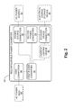
Fig. 2 is a block diagram of a nonexclusive illustrative example of a reconfigurable power converter. -
Fig. 3 is a schematic diagram of a nonexclusive illustrative example of a 3-phase asymmetric reconfigurable power system. -
Fig. 4 is a schematic diagram of a nonexclusive illustrative example of a 3-phase symmetric reconfigurable power system. -
Fig. 5 is a schematic diagram of a nonexclusive illustrative example of a single-phase asymmetric reconfigurable power system. -
Fig. 6 is a schematic diagram of a nonexclusive illustrative example of a single-phase symmetric reconfigurable power system. -
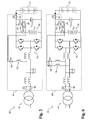
Fig. 7 is a schematic diagram of another nonexclusive illustrative example of a 3-phase asymmetric reconfigurable power system, shown with a first power converter connecting a photovoltaic DC power source to an electrical energy storage device. -
Fig. 8 is a schematic diagram of the reconfigurable power system ofFig. 7 , shown with the photovoltaic DC power source connected to the AC power grid by the first power converter and to the electrical energy storage device by a second power converter. -
Fig. 9 is a schematic diagram of the reconfigurable power system ofFig. 7 , shown with the first power converter connecting the photovoltaic DC power source to the AC power grid. -
Fig. 10 is a schematic diagram of the reconfigurable power system ofFig. 7 , shown with the photovoltaic DC power source connected to the AC power grid by the first power converter and the electrical energy storage device connected to the first power converter, and the AC power grid, by the second power converter. -
Fig. 11 is a schematic diagram of the reconfigurable power system ofFig. 7 , shown with the first power converter connecting the electrical energy storage device to the AC power grid. -
Fig. 12 is a schematic diagram of the reconfigurable power system ofFig. 7 , shown with the first power converter connecting the AC power grid to the electrical energy storage device. -
Fig. 13 is a daily timeline illustrating a nonexclusive illustrative implementation example, which may be suitable for one of the reconfigurable power systems and/or converters disclosed herein. -
Fig. 14 is a schematic diagram of another nonexclusive illustrative example of a 3-phase symmetric reconfigurable power system. -
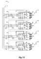
Fig. 15 is a schematic diagram of a nonexclusive illustrative example of a power plant that includes a plurality of reconfigurable power systems, such as the reconfigurable power system ofFig. 7 . - A nonexclusive illustrative example of a reconfigurable power system is shown generally at 20 in
Fig. 1 . Unless otherwise specified, thereconfigurable power system 20 may, but is not required to, contain at least one of the structures, components, functionalities, and/or variations described, illustrated, and/or incorporated herein. In the illustrated example, thepower system 20 includes aDC power source 22, an electricalenergy storage device 24, a connection to an AC power grid or ACpower grid connection 26, afirst power converter 28, and an auxiliary orsecond power converter 29. - The
DC power source 22 may include any DC source, such as an intermittent or non-base load source. For example, the DC power source may include at least one solar or photovoltaic (PV) cell. In some examples, at least a portion of the DC source may include other intermittent power sources such as wind or tidal power. However, some possible intermittent power sources, such as wind and tidal power, may need to be converted to DC before use with thereconfigurable power system 20. - The electrical
energy storage device 24 may include any suitable combination of devices or structures capable of storing electrical energy. Nonexclusive illustrative examples of such devices include, without limitation, electrochemical cells or batteries, capacitors, supercapacitors, flywheels, or the like. - The
first power converter 28 may be configured to selectively couple two or more of theDC power source 22, the electricalenergy storage device 24, the ACpower grid connection 26, and thesecond power converter 29. - The
second power converter 29 may be configured to selectively couple the electricalenergy storage device 24 to at least one of theDC power source 22 and thefirst power converter 28. Thesecond power converter 29 may be configured as a DC-DC converter. As will be more fully set out below, thesecond power converter 29 may be used in some examples where the electricalenergy storage device 24 is being charged and/or discharged. - Either or both of the
first power converter 28 and thesecond power converter 29 may include at least one switching element or device. The switching element or device may include at least one semiconductor switching device, such as a power transistor, a power MOSFET, an insulated gate bipolar transistor (IGBT), a gate turn-off thyristor (GTO), or the like. By changing the on-off duty ratio and frequency of the switching element or device, thefirst power converter 28 and/or thesecond power converter 29 can control its output voltage and frequency. - The
first power converter 28 may be configured to operate in a selected one of at least three modes. For example, thefirst power converter 28 may be configured to selectively operate or function as a DC-AC inverter, a DC-DC converter, or an AC-DC converter. Thefirst power converter 28 may be configured to function as a DC-AC inverter when coupling theDC power source 22 and/or the electricalenergy storage device 24 to the ACpower grid connection 26, such as to deliver power from the DC power source, the electrical energy storage device, or both to the AC power grid. When thefirst power converter 28 is configured as a DC-AC inverter that couples theDC power source 22 and the electricalenergy storage device 24 to the ACpower grid connection 26, the electrical energy storage device may be coupled to the DC power source and to the first power converter by way of thesecond power converter 29. Thefirst power converter 28 may be configured to function as a DC-DC converter when coupling theDC power source 22 to the electricalenergy storage device 24, such as to charge the electrical energy storage device. Thefirst power converter 28 may be configured to function as an AC-DC converter when coupling the ACpower grid connection 26 to the electricalenergy storage device 24, such as to charge the electrical energy storage device from the AC power grid. - A nonexclusive illustrative example of a reconfigurable power converter is shown generally at 30 in
Fig. 2 . Unless otherwise specified, thereconfigurable power converter 30 may, but is not required to, contain at least one of the structures, components, functionalities, and/or variations described, illustrated, and/or incorporated herein. In the illustrated example, thereconfigurable power converter 30 includes apower source connection 32, astorage device connection 34, agrid connection 36, afirst power converter 38, and an auxiliary or second power converter 39. Thepower source connection 32 may be configured to couple with aDC power source 22, thestorage device connection 34 may be configured to couple with an electricalenergy storage device 24, and thegrid connection 36 may be configured to couple with anAC power grid 40. - The
first power converter 38, which may include at least one semiconductor switching device, may be configured to selectively couple two or more of thepower source connection 32, thestorage device connection 34, thegrid connection 36, and the second power converter 39. Thefirst power converter 38 may be selectively configured as, for example, a DC-DC converter, a DC-AC inverter or an AC-DC converter. For example, when coupling thepower source connection 32 to thestorage device connection 34, thefirst power converter 38 may be configured as a DC-DC converter. When coupling thegrid connection 36 to at least one of thepower source connection 32, thestorage device connection 34 and the second power converter 39, thefirst power converter 38 may be configured as a DC-AC inverter. When coupling thegrid connection 36 to thestorage device connection 34, the power converter may be configured as an AC-DC converter. - The second power converter 39, which may be configured as a DC-DC converter and may include at least one semiconductor switching device, may be configured to selectively couple the
storage device connection 34 to at least one of thepower source connection 32 and thefirst power converter 38. - In some examples, the
reconfigurable power converter 30 may include a current-limiting structure ordevice 42, such as a resistor. The current-limiting structure ordevice 42 may be configured to selectively limit inrush current to an electricalenergy storage device 24 that is coupled with thestorage device connection 34. -
Figs. 3-6 illustrate further nonexclusive illustrative examples of reconfigurable power systems. A 3-phase asymmetricreconfigurable power system 52 is shown inFig. 3 , a 3-phase symmetricreconfigurable power system 54 is shown inFig. 4 , a single-phase asymmetricreconfigurable power system 56 is shown inFig. 5 , and a single-phase symmetricreconfigurable power system 58 is shown inFig. 6 . Unless otherwise specified, thereconfigurable power systems reconfigurable power systems DC power source 22, an electricalenergy storage device 24, an ACpower grid connection 26, afirst power converter 28 with a plurality ofconverter circuits 70, and asecond power converter 29. - As shown in
Figs. 3-6 , thepower converters 28 of thereconfigurable power systems 52 may include a plurality ofswitches power converters 28 may optionally include at least oneinductor 72 on the circuit path used to charge the electricalenergy storage device 24 from theDC power source 22, as will be set out below. - With regard to the asymmetric and symmetric configurations of the
reconfigurable power systems Figs. 3-6 , the asymmetric configuration may permit a reduction in manufacturing cost and/or physical size of the power converter. For example, the wiring would be simplified, theswitch 64 would only need to include a single switch, and only asingle inductor 72 would be needed. However, the symmetric configuration may permit more efficient utilization of theconverter circuits 70 within the power converter and/or equalize the losses across all of theconverter circuits 70, such as by equalizing the losses on the semiconductor switches in the power converter when using the DC power source to charge the battery, as will be set out below. - Another nonexclusive illustrative example of a reconfigurable power system is shown generally at 76 in
Figs. 7-12 . Unless otherwise specified, thereconfigurable power system 76 may, but is not required to, contain at least one of the structures, components, functionalities, and/or variations described, illustrated, and/or incorporated herein. As shown, thereconfigurable power system 76 includes aDC power source 22, an electricalenergy storage device 24, an ACpower grid connection 26, afirst power converter 28, and asecond power converter 29. As shown inFigs. 7-12 , theDC power source 22 of thereconfigurable power system 76 may include a plurality ofphotovoltaic cells 78, and the electricalenergy storage device 24 may include a battery. - The various operating modes or configurations of a reconfigurable power system and/or power converter may be explained more fully with reference to the
reconfigurable power system 76, and its first andsecond power converters Figs. 7-12 . - In the mode illustrated in
Fig. 7 , theswitches switches first power converter 28 of thereconfigurable power system 76 is coupling the plurality ofphotovoltaic cells 78 of theDC power source 22 to the electricalenergy storage device 24, with a power flow as generally suggested by thearrow 82. In this mode, thefirst power converter 28 is configured to function as a DC-DC converter such that thephotovoltaic cells 78 charge the electricalenergy storage device 24. - In some examples where the
reconfigurable power system 76 is operating in the mode illustrated inFig. 7 , thefirst power converter 28 may perform maximum power point tracking (MPPT) with thephotovoltaic cells 78. Under maximum power point tracking, thefirst power converter 28 attempts to function as a substantially optimal electrical load for the photovoltaic cells in order to extract a relatively high level of power from the photovoltaic cells. In some examples, the level of power extracted from the photovoltaic cells during maximum power point tracking may be near the maximum or even the maximum power available from the photovoltaic cells. - In the mode illustrated in
Fig. 8 , theswitches switches first power converter 28 of thereconfigurable power system 76 is coupling the plurality ofphotovoltaic cells 78 of theDC power source 22 to the electricalenergy storage device 24 and to the ACpower grid connection 26, with the electricalenergy storage device 24 being coupled to the plurality ofphotovoltaic cells 78 and to thefirst power converter 28 by way of thesecond power converter 29. In this mode, thefirst power converter 28 is configured to function as a DC-AC inverter such that thephotovoltaic cells 78 deliver power to the AC power grid through thefirst power converter 28 while charging the electricalenergy storage device 24 through thesecond power converter 29, with a power flow as generally suggested by thearrows 84. - In some examples where the
reconfigurable power system 76 is operating in the mode illustrated inFig. 8 , thefirst power converter 28 and/or thesecond power converter 29 may perform maximum power point tracking with thephotovoltaic cells 78. Thefirst power converter 28 is able to perform maximum power point tracking for the photovoltaic cells when thereconfigurable power system 76 is operating in the mode illustrated inFig. 8 because coupling the electricalenergy storage device 24 to the plurality ofphotovoltaic cells 78 by way of thesecond power converter 29 means that the voltage of thephotovoltaic cells 78, vpv , need not be governed by the voltage of the electricalenergy storage device 24, vbat. - As may be understood, a relatively lower power may flow through the
second power converter 29 to charge and/or discharge the electricalenergy storage device 24 as compared to a rated power for thereconfigurable power system 76. Thus, for example, asecond power converter 29 having a power rating that is only about 20% to about 30% of the rated power of thefirst power converter 28 and/or thereconfigurable power system 76 may be sufficient. Furthermore, inclusion of thesecond power converter 29 may permit more flexibility in selection and/or sizing of the electricalenergy storage device 24 because Inclusion of thesecond power converter 29 may allow for avoiding operational modes in which the voltage of thephotovoltaic cells 78, vpv, is governed by the voltage of the electricalenergy storage device 24, vbat. - In the mode illustrated in
Fig. 9 , theswitches switches first power converter 28 of thereconfigurable power system 76 is coupling the plurality ofphotovoltaic cells 78 to the ACpower grid connection 26. In this mode, thefirst power converter 28 is configured to function as a DC-AC inverter such that thephotovoltaic cells 78 deliver power to the AC power grid, with a power flow as generally suggested by thearrow 86. In some examples where thereconfigurable power system 76 is operating in the mode illustrated inFig. 9 , thefirst power converter 28 may perform maximum power point tracking with thephotovoltaic cells 78. - In the mode illustrated in
Fig. 10 , theswitches switches first power converter 28 of thereconfigurable power system 76 is coupling the plurality ofphotovoltaic cells 78 and the electricalenergy storage device 24 to the ACpower grid connection 26, with the electricalenergy storage device 24 being coupled to the plurality ofphotovoltaic cells 78 and to thefirst power converter 28 by way of thesecond power converter 29. In this mode, thefirst power converter 28 is configured to function as a DC-AC inverter such that thephotovoltaic cells 78 and the electricalenergy storage device 24 both deliver power to the AC power grid, with a power flow as generally suggested by thearrows 88 and with thesecond power converter 29 discharging the electricalenergy storage device 24. - In some examples where the
reconfigurable power system 76 is operating in the mode illustrated inFig. 10 , thefirst power converter 28 may perform maximum power point tracking with thephotovoltaic cells 78. Thefirst power converter 28 is able to perform maximum power point tracking for the photovoltaic cells when thereconfigurable power system 76 is operating in the mode illustrated inFig. 10 because discharging the electricalenergy storage device 24 through thesecond power converter 29 to deliver power to the AC power grid means that the voltage of thephotovoltaic cells 78, vpv , need not be governed by the voltage of the electricalenergy storage device 24, vbat. - In the mode illustrated in
Fig. 11 , theswitches switches first power converter 28 of thereconfigurable power system 76 is coupling the electricalenergy storage device 24 to the ACpower grid connection 26. In this mode, thefirst power converter 28 is configured to function as a DC-AC inverter such that the electricalenergy storage device 24 delivers power to the AC power grid, with a power flow as generally suggested by thearrow 90. - In the mode illustrated in
Fig. 12 , theswitches switches first power converter 28 of thereconfigurable power system 76 is coupling the electricalenergy storage device 24 to the ACpower grid connection 26. In this mode, thefirst power converter 28 is configured to function as an AC-DC converter such that the electricalenergy storage device 24 is charged from the AC power grid, with a power flow as generally suggested by thearrow 92. - in some examples, peak hourly grid load demand and/or peak power consumption may generally occur, between about 4:00 PM (16:00) and about 8:00 PM (20:00). However, peak photovoltaic (PV) power generation may generally occur, for example, between about 11:00 AM (11:00) and about 3:00 PM (15:00). Thus, in some examples, hourly grid load demand may not match well with purely photovoltaic power generation or photovoltaic power generation without electrical energy storage. However, if photovoltaic power generation is combined with electrical energy storage, such as where a power system includes both photovoltaic cells and electrical energy storage devices, a better match to the grid load demand may be realized. In particular, photovoltaic energy generated before the hours of peak grid load demand can be stored in a suitable electrical energy storage device and then used during the hours of peak grid load demand.
- The following paragraphs describe nonexclusive illustrative examples of methods for or of operating reconfigurable power systems, such as by selectively coupling two or more of a DC power source, an electrical energy storage device, and an AC power grid connection, using the concepts and components disclosed herein. Although the actions of the disclosed methods may be performed in the order in which they are presented below, it is within the scope of this disclosure for the actions, either alone or in various combinations, to be performed before and/or after any of the other actions.
- When used as part of a power system and/or power plant, the reconfigurable power converters and reconfigurable power systems disclosed herein may be used and/or operated in any combination of modes suitable to supply power to the grid load demand at a given time of day. For example, the
reconfigurable power system 76 ofFigs. 7-12 may be sequentially operated in the modes illustrated in respective ones ofFigs. 7-12 over the course of a normal day. - With reference to
Fig. 13 , a nonexclusive illustrative example of a method of operating a reconfigurable power system may include three sequential modes of operation:MODE 1,MODE 2, andMODE 3. InMODE 1, a first power converter may be configured as a DC-DC converter that couples a DC power source, which may include at least one photovoltaic or solar cell, to an electrical energy storage device to charge the electrical energy storage device, which may include a battery. The reconfigurable power system may be operated inMODE 1 between, for example, about 8:00 AM (08:00) and about 3:00 PM (15:00), which may include the times of day that provide relatively high and/or peak photovoltaic power generation, but are before the hours of peak grid load demand. InMODE 2, the first power converter may be configured as a DC-AC inverter that couples the DC power source to an AC power grid connection, while a second power converter is configured as a DC-DC converter and couples the electrical energy storage device to the DC power source and the first power converter, such that power is delivered to the AC power grid connection from both the DC power source and the energy stored in the electrical energy storage device. The reconfigurable power system may be operated inMODE 2 between, for example, about 3:00 PM (15:00) and about 6:00 PM (18:00), which may include the times of day during which peak grid load demand occurs and during which photovoltaic power generation is still available. InMODE 3, the first power converter may be configured as a DC-AC inverter that couples the electrical energy storage device to the AC power grid connection to deliver stored energy to the AC power grid. The reconfigurable power system may be operated inMODE 3 between, for example, about 6:00 PM (18:00) and about 10:00 PM (22:00), which may include the times of day where photovoltaic power generation may not be available but the grid load demand is still high enough to warrant delivering stored energy from the energy storage device to the AC power grid. - In some examples, the first power converter may perform maximum power point tracking for at least one solar or photovoltaic cell when the first power converter is configured as a DC-DC converter that couples the DC power source to the electrical energy storage device. Thus, in
MODE 1, the first power converter may perform maximum power point tracking while charging a battery from a photovoltaic cell. - In some examples, methods of operating reconfigurable power systems may include configuring the first power converter as a DC-AC inverter and coupling the DC power source and/or the electrical energy storage device to the AC power grid therewith, with the second power converter coupling the electrical energy storage device to the DC power source and to the first power converter. In such examples, the first power converter may perform maximum power point tracking for at least one solar or photovoltaic cell when the first power converter is configured as a DC-AC inverter that couples the DC power source and/or the electrical energy storage device to the AC power grid. Thus, in
Mode 2 the first power converter may perform maximum power point tracking while delivering power to the AC power grid from both the DC power source and the electrical energy storage device. - In some examples, methods of operating reconfigurable power systems may include configuring the first power converter as an AC-DC converter and coupling the AC power grid to the electrical energy storage device therewith. In such an example, power may be drawn from the AC power grid to charge the electrical energy storage device, such as during hours of low grid load demand.
- In some examples, a capacitor may be connected in parallel with the electrical energy storage device. In such examples, the methods of operating reconfigurable power systems, such as when transitioning from the
MODE 1 to theMODE 2 discussed above, may include uncoupling the DC power source from the electrical energy storage device, equalizing a voltage of the electrical energy storage device to a voltage of the capacitor, and then configuring the first power converter as a DC-AC inverter and coupling the DC power source and the electrical energy storage device to the AC power grid after equalizing the voltage of the electrical energy storage device to the voltage of the capacitor, with the electrical energy storage device being coupled to the DC power source and the first power converter by way of the second power converter. - Equalizing the voltage of the electrical energy storage device to the voltage of the capacitor may reduce or prevent potentially large inrush currents that may otherwise flow into the electrical energy storage device from the capacitor when the DC power source is connected to the electrical energy storage device, such as during a transition or change from
MODE 1 toMODE 2. Reducing or preventing large inrush currents into the electrical energy storage device may reduce or prevent damage to the electrical energy storage device and/or improve its lifetime. - In some examples, equalizing the voltage of the electrical energy storage device to the voltage of the capacitor may include connecting the electrical energy storage device to the capacitor through a current-limiting device, such as a resistor, which may limit the current flowing into the electrical energy storage device until the voltage levels are equalized. Such an example may be further explained with reference to the nonexclusive illustrative example of a reconfigurable power system shown generally at 96 in
Fig. 14 . Unless otherwise specified, thereconfigurable power system 96 may, but is not required to, contain at least one of the structures, components, functionalities, and/or variations described, illustrated, and/or incorporated herein. As shown, thereconfigurable power system 96 includes aDC power source 22 having a plurality ofphotovoltaic cells 78, an electricalenergy storage device 24 that includes a battery, an ACpower grid connection 26, afirst power converter 28, asecond power converter 29, acapacitor 98 connected in parallel with the electricalenergy storage device 24 and theDC power source 22, aresistor 100, and a plurality ofswitches - In
MODE 1 thepower system 96 would be configured similarly toFig. 7 , with theswitches switches first power converter 28 couples theDC power source 22 to the electricalenergy storage device 24. InMODE 2 thepower system 96 would be configured similarly toFig. 10 , with theswitches switches first power converter 28 couples theDC power source 22 and the electricalenergy storage device 24 to the ACpower grid connection 26, with the electricalenergy storage device 24 being coupled to theDC power source 22, thefirst power converter 28 and the ACpower grid connection 26 by way of thesecond power converter 29. When transitioning thereconfigurable power system 96 fromMODE 1 toMODE 2, theswitch 102 may be opened and theswitch 104 may then be closed to selectively series-couple the electricalenergy storage device 24 to thecapacitor 98 through theresistor 100 to equalize the voltage, vbat, of the electricalenergy storage device 24 to the voltage, vpv , of thecapacitor 98 prior to opening theswitch 104 and closing theswitches DC power source 22 and the electricalenergy storage device 24 to the ACpower grid connection 26, with theswitch 64 being opened before closing theswitch 66. - When transitioning the
reconfigurable power system 96 from theMODE 2 to theMODE 3 discussed above, theswitch 102 need only be opened. However, operation of thefirst power converter 28 and/or itsconverter circuits 70 may be discontinued while opening theswitch 102, which may prevent or reduce transient performance. - A nonexclusive illustrative example of a power plant is shown generally at 110 in Fig. 18. Unless otherwise specified, the
power plant 110 may, but is not required to, contain at least one of the structures, components, functionalities, and/or variations described, illustrated, and/or incorporated herein. In the illustrated example, thepower plant 110 includes a plurality ofreconfigurable power systems 76, which are connected together in parallel and assembled into thepower plant 110, and anAC grid connection 112. In the illustrated example, the plurality ofreconfigurable power systems 76 includes a firstreconfigurable power system 114, a secondreconfigurable power system 116, a thirdreconfigurable power system 118, and a fourthreconfigurable power system 120. - As may be understood, a suitable number of suitable
reconfigurable power systems 76 may be assembled into any suitablysized power plant 110. Nonexclusive illustrative examples of suitable sizes forpower plant 110 may include 50 KW, 100 KW, 200 KW, 250 KW, 500 KW, or even 1000 KW or larger. Furthermore, as may be understood, the variousreconfigurable power systems 76 within thepower plant 110 may be configured into suitable combinations of modes, such as those illustrated inFigs. 7-12 , to more closely match the power delivered from thepower plant 110 to theAC grid connection 112. - For example, when the power generated by or available from the
DC power sources 22 of thereconfigurable power systems 76 of thepower plant 110 is greater than the grid load demand at a particular time, thepower plant 110 may be configured such that only the amount of the power requested by the AC power grid is delivered to theAC grid connection 112, with the rest of the power generated by or available from theDC power sources 22 being stored into one or more of the electricalenergy storage devices 24. In such an example, at least one of the reconfigurable power systems may be configured to deliver the power generated by its DC power source to the AC power grid, at least one of the reconfigurable power systems may be configured to deliver a portion of the power generated by its DC power source to the AC power grid while storing the remainder of its generated power in its electrical energy storage device, and at least one of the reconfigurable power systems may be configured to store the power generated by its DC power source in its electrical energy storage device. -
Fig. 15 illustrates an example where thepower plant 110 is configured to store generated power that is in excess of the grid load demand at a particular time. InFig. 15 , the firstreconfigurable power system 114 is configured as inFig. 9 , with itsfirst power converter 28 configured as a DC-AC inverter that couples itsDC power source 22 to its ACpower grid connection 26 to deliver power from its DC power source to its AC power grid connection. In some examples, thefirst power converter 28 of the firstreconfigurable power system 114 may perform maximum power point tracking for thephotovoltaic cells 78 of its DC power source. The secondreconfigurable power system 116 is configured as inFig. 8 , with itsfirst power converter 28 configured as a DC-AC inverter that couples itsDC power source 22 to its electricalenergy storage device 24 and to its ACpower grid connection 26 to deliver power from itsDC power source 22 to the AC power grid and to store energy in its electrical energy storage device. As shown inFig. 15 , the electricalenergy storage device 24 of the secondreconfigurable power system 116 is coupled to the DC power source and the first power converter of the secondreconfigurable power system 116 by way of the second power converter, which allows maximum power point tracking by the first power converter of the secondreconfigurable power system 116. The thirdreconfigurable power system 118 and the fourthreconfigurable power system 120 are configured as inFig. 7 , with theirfirst power converters 28 configured as DC-DC converters that couple theirDC power sources 22 to their electricalenergy storage devices 24 to store energy therein. In some examples, the first power converters of the third and fourthreconfigurable power system photovoltaic cells 78 of their DC power sources. - The following paragraphs present a nonexclusive list of examples of how the
power plant 110 may be configured to supply power to and/or otherwise interact with an AC power grid. - Where the grid load demand does not warrant delivering power from the
DC power sources 22 of thereconfigurable power systems 76 of thepower plant 110 to the AC power grid, all of the power generated by theDC power sources 22 may be stored in the electricalenergy storage devices 24. In such an example, each of the power plant'sreconfigurable power systems 76 may be configured as inFig. 7 , with itsfirst power converter 28 configured as a DC-DC converter that couples itsDC power source 22 to its electricalenergy storage device 24. - Where the grid load demand equals the power generated by or available from the
DC power sources 22 of thereconfigurable power systems 76 of thepower plant 110, thepower plant 110 may be configured such that all power generated by theDC power sources 22 is delivered to theAC grid connection 112. In such an example, each of the power plant'sreconfigurable power systems 76 may be configured as inFig. 9 , with thefirst power converter 28 configured as a DC-AC inverter that couples itsDC power source 22 to itsAC grid connection 26. - Where the grid load demand exceeds the power generated by or available from the
DC power sources 22 of thereconfigurable power systems 76 of thepower plant 110, thepower plant 110 may be configured to deliver power to theAC grid connection 112 from at least some of the electricalenergy storage devices 24 in addition to the power generated by theDC power sources 22. In such an example, at least some of the power plant'sreconfigurable power systems 76 may be configured as inFig. 10 , with thefirst power converter 28 configured as a DC-AC inverter that couples itsDC power source 22 and, by way of itssecond power converter 29, its electricalenergy storage devices 24 to itsAC grid connection 26. - When the
DC power sources 22 of thereconfigurable power systems 76 of thepower plant 110 are unable to supply power, but a grid load demands exists, thepower plant 110 may be configured such that the electricalenergy storage devices 24 of at least some of thereconfigurable power systems 76 deliver power to theAC grid connection 112. In such an example, at least some of the power plant'sreconfigurable power systems 76 may be configured as inFig. 11 , with thefirst power converter 28 configured as a DC-AC inverter that couples its electricalenergy storage devices 24 to its ACpower grid connection 26. - When power is available from the AC power grid, at least some of the electrical
energy storage devices 24 of thereconfigurable power systems 76 of thepower plant 110 may be charged using power drawn from theAC grid connection 112. In such an example, at least some of the power plant'sreconfigurable power systems 76 may be configured as inFig. 12 , with thefirst power converter 28 configured as an AC-DC converter that couples its ACpower grid connection 26 to its electricalenergy storage devices 24. - The methods disclosed herein may at least partially be embodied as or take the form of the methods described herein, as well as of a transitory or non-transitory computer readable medium having a plurality of machine- or computer-readable instructions stored thereon that, when executed by a processor, carry out operations of the disclosed methods and systems. The computer-readable medium may be any medium that can contain, store, communicate, propagate, or transport program instruction for use by or in connection with the instruction execution system, apparatus, or device and may, by way of example but without limitation, be an electronic, magnetic, optical, electromagnetic, infrared, or semiconductor system, apparatus, device, or propagation medium or other suitable medium upon which the program is recorded. More specific examples (a non-exhaustive list) of such a computer-readable medium may include: a portable computer diskette, a hard disk, a random access memory (RAM), a read-only memory (ROM), an erasable programmable read-only memory (EPROM or Flash memory), an optical fiber, a portable compact disc read-only memory (CD-ROM), an optical storage device, a transmission media such as those supporting the Internet or an intranet, or a magnetic storage device. Computer program code or instructions for carrying out operations of the disclosed methods and systems may be written in any suitable programming language provided it allows achieving the previously described technical results. The instructions may be configured for execution on any system, apparatus or device having sufficient processing power and access to any required data.
- It is believed that the disclosure set forth herein encompasses multiple distinct inventions with independent utility. While each of these inventions has been disclosed in its preferred form, the specific embodiments thereof as disclosed and illustrated herein are not to be considered in a limiting sense as numerous variations are possible. The subject matter of the disclosure includes all novel and non-obvious combinations and subcombinations of the various elements, features, functions and/or properties disclosed herein. Similarly, recitation in the disclosure and/or the claims of "a" or "a first" element, or the equivalent thereof, should be understood to include incorporation of one or more such elements, neither requiring nor excluding two or more such elements.
- It is believed that the following claims particularly point out certain combinations and subcombinations that are directed to one of the disclosed inventions and are novel and non-obvious. Inventions embodied in other combinations and subcombinations of features, functions, elements and/or properties may be claimed through amendment of the present claims or presentation of new claims in this or a related application. Such amended or new claims, whether they are directed to a different invention or directed to the same invention, whether different, broader, narrower or equal in scope to the original claims, are also regarded as included within the subject matter of the inventions of the present disclosure.
Claims (19)
- A reconfigurable power system, comprising:a DC power source;an electrical energy storage device;an AC power grid connection;a first power converter configured to selectively couple two or more of the DC power source, the electrical energy storage device, and the AC power grid connection; anda second power converter configured to selectively couple the electrical energy storage device to at least one of the DC power source and the first power converter, wherein the second power converter is configured as a DC-DC converter.
- The reconfigurable power system of claim 1, wherein the DC power source includes at least one photovoltaic cell, and the first power converter is configured to perform maximum power point tracking for the at least one photovoltaic cell when coupling the DC power source to at least one of the electrical energy storage device and the AC power grid connection.
- The reconfigurable power system of claim 1, wherein the electrical energy storage device includes a battery, or at least one of the first and second power converters includes at least one semiconductor switching device.
- The reconfigurable power system of claim 1, wherein the first power converter is configured to selectively function as a DC-DC converter, a DC-AC inverter, or an AC-DC converter.
- The reconfigurable power system of claim 4, wherein:the first power converter is configured to function as the DC-DC converter when coupling the DC power source to the electrical energy storage device to charge the electrical energy storage device;when the first power converter couples the DC power source and the electrical energy storage device to the AC power grid connection, the first power converter is configured to function as the DC-AC inverter and the second power converter couples the electrical energy storage device to the DC power source and the first power converter; andthe first power converter is configured to function as the AC-DC converter when coupling the AC power grid connection to the electrical energy storage device to charge the electrical energy storage device.
- The reconfigurable power system of claim 1, wherein:the reconfigurable power system is configured to operate in a selected one of at least three modes;in a first one of the modes the first power converter is configured as a DC-DC converter coupling the DC power source to the electrical energy storage device;in a second one of the modes the first power converter is configured as a DC-AC inverter coupling the DC power source and the electrical energy storage device to the AC power grid connection and the second power converter couples the electrical energy storage device to the DC power source and the first power converter; andin a third one of the modes the first power converter is configured as an AC-DC converter coupling the AC power grid connection to the electrical energy storage device.
- The reconfigurable power system of claim 1, wherein:the reconfigurable power system is configured to operate in a selected one of at least three modes;in a first one of the modes the first power converter is configured as a DC-DC converter coupling the DC power source to the electrical energy storage device;in a second one of the modes the first power converter is configured as a DC-AC inverter coupling the DC power source and the electrical energy storage device to the AC power grid connection and the second power converter couples the electrical energy storage device to the DC power source and the first power converter; andin a third one of the modes the first power converter is configured as a DC-AC inverter coupling the electrical energy storage device to the AC power grid connection.
- The reconfigurable power system of claim 7, where in a fourth one of the at least three modes the first power converter is configured as a DC-AC inverter coupling the DC power source to the AC power grid connection.
- The reconfigurable power system of claim 7, comprising:a capacitor connected in parallel with the electrical energy storage device and the DC power source; anda resistor configured to selectively series-couple the electrical energy storage device to the capacitor.
- The reconfigurable power system of claim 1 assembled into a power plant, the power plant comprising a plurality of the reconfigurable power systems connected together.
- The power plant of claim 10, wherein:the plurality of the reconfigurable power systems comprises a first reconfigurable power system and a second reconfigurable power system;in the first reconfigurable power system, the first power converter of the first reconfigurable power system is selectively configured as a DC-DC converter that couples the DC power source of the first reconfigurable power system to the electrical energy storage device of the first reconfigurable power system; andin the second reconfigurable power system, the first power converter of the second reconfigurable power system is selectively configured as a DC-AC inverter that couples the AC power grid connection of the second reconfigurable power system to at least one of the DC power source of the second reconfigurable power system and the electrical energy storage device of the second reconfigurable power system, and the second power converter of the second reconfigurable power system couples the electrical energy storage device of the second reconfigurable power system to at least one of the DC power source of the second reconfigurable power system and the first power converter of the second reconfigurable power system.
- A reconfigurable power converter, comprising:a power source connection configured to couple with a DC power source;a storage device connection configured to couple with an electrical energy storage device;a grid connection configured to couple with an AC power grid;a first power converter configured to selectively couple two or more of the power source connection, the storage device connection, and the grid connection, wherein the first power converter is selectively configured as one of:a DC-DC converter when coupling the power source connection to the storage device connection;a DC-AC inverter when coupling at least one of the power source connection and the storage device connection to the grid connection; andan AC-DC converter when coupling the grid connection to the storage device connection; anda second power converter configured to selectively couple the storage device connection to at least one of the power source connection and the first power converter, wherein the second power converter is configured as a DC-DC converter.
- The reconfigurable power converter of claim 12, wherein the DC power source includes at least one photovoltaic cell, and the first power converter is configured to perform maximum power point tracking for the at least one photovoltaic cell when coupling the power source connection to at least one of the storage device connection and the grid connection.
- The reconfigurable power converter of claim 12, wherein the electrical energy storage device includes a battery, or at least one of the first and second power converters includes at least one semiconductor switching device.
- The reconfigurable power converter of claim 12, comprising a resistor configured to selectively limit inrush current to an electrical energy storage device coupled with the storage device connection.
- A method of operating a reconfigurable power system comprising a DC power source, an electrical energy storage device, and an AC power grid connection, the method comprising:configuring a first power converter as a DC-DC converter and coupling the DC power source to the electrical energy storage device therewith;configuring the first power converter as a DC-AC inverter and coupling the DC power source to the AC power grid connection therewith while a second power converter couples the electrical energy storage device to the DC power source and the first power converter, wherein the second power converter is configured as a DC-DC converter; andconfiguring the first power converter as a DC-AC inverter and coupling the electrical energy storage device to the AC power grid connection therewith.
- The method of claim 16, wherein the DC power source includes at least one solar cell, and the first power converter is configured to perform maximum power point tracking for the at least one solar cell when coupling the DC power source to the electrical energy storage device and the AC power grid connection.
- The method of claim 16, comprising configuring the first power converter as an AC-DC converter and coupling the AC power grid connection to the electrical energy storage device.
- The method of claim 16, wherein a capacitor is connected in parallel with the electrical energy storage device, and the method comprises:uncoupling the DC power source from the electrical energy storage device;equalizing a voltage of the electrical energy storage device to a voltage of the capacitor; and
configuring the first power converter as a DC-AC inverter and coupling the DC power source and the electrical energy storage device to the AC power grid connection after equalizing the voltage of the electrical energy storage device to the voltage of the capacitor, wherein the electrical energy storage device is coupled to the DC power source and the first power converter by way of the second power converter.
Applications Claiming Priority (1)
| Application Number | Priority Date | Filing Date | Title |
|---|---|---|---|
| US201161476021P | 2011-04-15 | 2011-04-15 |
Publications (2)
| Publication Number | Publication Date |
|---|---|
| EP2511999A1 true EP2511999A1 (en) | 2012-10-17 |
| EP2511999B1 EP2511999B1 (en) | 2017-07-12 |
Family
ID=45930575
Family Applications (1)
| Application Number | Title | Priority Date | Filing Date |
|---|---|---|---|
| EP12159377.6A Active EP2511999B1 (en) | 2011-04-15 | 2012-03-14 | Reconfigurable power converters, systems and plants |
Country Status (3)
| Country | Link |
|---|---|
| US (1) | US20130062953A1 (en) |
| EP (1) | EP2511999B1 (en) |
| CN (1) | CN102738824B (en) |
Cited By (2)
| Publication number | Priority date | Publication date | Assignee | Title |
|---|---|---|---|---|
| US9537319B2 (en) | 2011-04-15 | 2017-01-03 | North Carolina State University | Reconfigurable power systems and converters |
| WO2020190265A1 (en) * | 2019-03-15 | 2020-09-24 | General Electric Company | Customizable power converter and customizable power conversion system |
Families Citing this family (10)
| Publication number | Priority date | Publication date | Assignee | Title |
|---|---|---|---|---|
| US9312699B2 (en) | 2012-10-11 | 2016-04-12 | Flexgen Power Systems, Inc. | Island grid power supply apparatus and methods using energy storage for transient stabilization |
| US10289080B2 (en) | 2012-10-11 | 2019-05-14 | Flexgen Power Systems, Inc. | Multi-generator applications using variable speed and solid state generators for efficiency and frequency stabilization |
| US9553517B2 (en) * | 2013-03-01 | 2017-01-24 | Fllexgen Power Systems, Inc. | Hybrid energy storage system and methods |
| WO2015122994A1 (en) * | 2014-02-13 | 2015-08-20 | Nextronex, Inc. | Grid tie solar inverter system with storage |
| US9923487B2 (en) * | 2014-04-14 | 2018-03-20 | Tmeic Corporation | Hybrid power converter for renewable energy power plant |
| CN107534294B (en) | 2014-12-30 | 2021-07-30 | 弗莱斯金电力系统公司 | Transient power stabilization device with active and reactive power control |
| JP2016187292A (en) * | 2015-03-27 | 2016-10-27 | パナソニックIpマネジメント株式会社 | Power storage system and management device |
| CN108475940A (en) * | 2015-12-31 | 2018-08-31 | 安辛可公司 | For managing the method and apparatus for substituting the power flow between energy source and storage device |
| WO2019113771A1 (en) * | 2017-12-12 | 2019-06-20 | Abb Schweiz Ag | Reconfigurable electric vehicle charging system |
| JP2023043076A (en) * | 2021-09-15 | 2023-03-28 | 株式会社東芝 | Bypass circuit, control method of power system, and program |
Citations (6)
| Publication number | Priority date | Publication date | Assignee | Title |
|---|---|---|---|---|
| US6057665A (en) | 1998-09-18 | 2000-05-02 | Fire Wind & Rain Technologies Llc | Battery charger with maximum power tracking |
| US6590793B1 (en) | 1996-08-23 | 2003-07-08 | Canon Kabushiki Kaisha | Electric power supplying apparatus using unstable electric power supply and control method therefor |
| US6914418B2 (en) | 2003-04-21 | 2005-07-05 | Phoenixtec Power Co., Ltd. | Multi-mode renewable power converter system |
| US7072194B2 (en) | 2002-03-28 | 2006-07-04 | Curtin University Of Technology | Power conversion system and method of converting power |
| US20100008119A1 (en) | 2008-01-31 | 2010-01-14 | General Electric Company | Solar power generation stabilization system and method |
| US7834580B2 (en) | 2007-07-27 | 2010-11-16 | American Power Conversion Corporation | Solar powered apparatus |
Family Cites Families (14)
| Publication number | Priority date | Publication date | Assignee | Title |
|---|---|---|---|---|
| US3686867A (en) * | 1971-03-08 | 1972-08-29 | Francis R Hull | Regenerative ranking cycle power plant |
| JP2005526363A (en) * | 2002-05-16 | 2005-09-02 | バラード パワー システムズ インコーポレイティド | Power facility with an array of adjustable fuel cell systems |
| US6949843B2 (en) * | 2003-07-11 | 2005-09-27 | Morningstar, Inc. | Grid-connected power systems having back-up power sources and methods of providing back-up power in grid-connected power systems |
| JP2005151662A (en) * | 2003-11-13 | 2005-06-09 | Sharp Corp | Inverter device and distributed power supply system |
| US7684222B2 (en) * | 2004-03-24 | 2010-03-23 | Eaton Corporation | Power conversion apparatus with DC bus precharge circuits and methods of operation thereof |
| US7248946B2 (en) * | 2004-05-11 | 2007-07-24 | Advanced Energy Conversion, Llc | Inverter control methodology for distributed generation sources connected to a utility grid |
| JP4506353B2 (en) * | 2004-08-25 | 2010-07-21 | 株式会社日立製作所 | Water supply control device for steam generator in power plant |
| RU2475923C2 (en) * | 2007-05-08 | 2013-02-20 | Американ Пауэр Конвершн Корпорейшн | Alternative source energy control |
| WO2009155445A2 (en) * | 2008-06-18 | 2009-12-23 | Premium Power Corporation | Integrated renewable energy generation and storage systems and associated methods |
| FI122046B (en) * | 2009-01-12 | 2011-07-29 | Abb Oy | solar power plants |
| CN101710716A (en) * | 2009-11-13 | 2010-05-19 | 南京航空航天大学 | Grid-connected inverter capable of reducing electrolytic capacitance |
| KR101084216B1 (en) * | 2009-12-23 | 2011-11-17 | 삼성에스디아이 주식회사 | Energy storage system and method for controlling thereof |
| JP5627264B2 (en) * | 2010-03-27 | 2014-11-19 | 三洋電機株式会社 | Power supply device for vehicle and vehicle equipped with this power supply device |
| KR101410000B1 (en) * | 2012-05-16 | 2014-07-02 | 엘지전자 주식회사 | Energy storage device and method for controlling the same |
-
2012
- 2012-03-12 US US13/417,435 patent/US20130062953A1/en not_active Abandoned
- 2012-03-14 EP EP12159377.6A patent/EP2511999B1/en active Active
- 2012-04-13 CN CN201210112402.1A patent/CN102738824B/en active Active
Patent Citations (6)
| Publication number | Priority date | Publication date | Assignee | Title |
|---|---|---|---|---|
| US6590793B1 (en) | 1996-08-23 | 2003-07-08 | Canon Kabushiki Kaisha | Electric power supplying apparatus using unstable electric power supply and control method therefor |
| US6057665A (en) | 1998-09-18 | 2000-05-02 | Fire Wind & Rain Technologies Llc | Battery charger with maximum power tracking |
| US7072194B2 (en) | 2002-03-28 | 2006-07-04 | Curtin University Of Technology | Power conversion system and method of converting power |
| US6914418B2 (en) | 2003-04-21 | 2005-07-05 | Phoenixtec Power Co., Ltd. | Multi-mode renewable power converter system |
| US7834580B2 (en) | 2007-07-27 | 2010-11-16 | American Power Conversion Corporation | Solar powered apparatus |
| US20100008119A1 (en) | 2008-01-31 | 2010-01-14 | General Electric Company | Solar power generation stabilization system and method |
Cited By (3)
| Publication number | Priority date | Publication date | Assignee | Title |
|---|---|---|---|---|
| US9537319B2 (en) | 2011-04-15 | 2017-01-03 | North Carolina State University | Reconfigurable power systems and converters |
| WO2020190265A1 (en) * | 2019-03-15 | 2020-09-24 | General Electric Company | Customizable power converter and customizable power conversion system |
| US11804771B2 (en) | 2019-03-15 | 2023-10-31 | General Electric Company | Customizable power converter and customizable power conversion system |
Also Published As
| Publication number | Publication date |
|---|---|
| CN102738824B (en) | 2016-10-19 |
| US20130062953A1 (en) | 2013-03-14 |
| CN102738824A (en) | 2012-10-17 |
| EP2511999B1 (en) | 2017-07-12 |
Similar Documents
| Publication | Publication Date | Title |
|---|---|---|
| US9537319B2 (en) | Reconfigurable power systems and converters | |
| EP2511999B1 (en) | Reconfigurable power converters, systems and plants | |
| Kumar et al. | Multi-input multi-output converter with battery charger for low power applications | |
| She et al. | On integration of solid-state transformer with zonal DC microgrid | |
| Yu et al. | Power management for DC microgrid enabled by solid-state transformer | |
| KR101168078B1 (en) | Multi-input bidirectional dc-dc converter | |
| Sun et al. | Design and test of a new two-stage control scheme for SMES-battery hybrid energy storage systems for microgrid applications | |
| Cansiz et al. | Integration of a SMES–battery-based hybrid energy storage system into microgrids | |
| WO2012144357A1 (en) | Power supply device, control method for power supply device, and dc power supply system | |
| JP5290349B2 (en) | DC power supply system and control method thereof | |
| CN106877368A (en) | A kind of photovoltaic generation micro-grid system hybrid energy-storing control method | |
| CN107612408B (en) | Energy storage converter and energy storage system | |
| CN110994968B (en) | Pre-charging circuit, inverter and power generation system | |
| CN104218805A (en) | Unipolar-bipolar convertible direct-current converter | |
| Ryu et al. | Test bed implementation of 380V DC distribution system using isolated bidirectional power converters | |
| US9257859B2 (en) | Dynamic battery control based on demand | |
| CN108539841A (en) | Combination DC-DC converter for hybrid power source system | |
| Bozchalui et al. | Optimal operation of Energy Storage in distribution systems with Renewable Energy Resources | |
| Shreelakshmi et al. | High gain, high efficiency bi-directional DC-DC converter for battery charging applications in stand-alone Photo-Voltaic systems | |
| Bi et al. | An impedance source modular DC/DC converter for energy storage system: Analysis and design | |
| Chiu et al. | Design and implementation of a high‐efficiency bidirectional DC‐DC Converter for DC micro‐grid system applications | |
| Binu Ben Jose et al. | Simple power electronic controller for photovoltaic fed grid‐tied systems using line commutated inverter with fixed firing angle | |
| Karthik Kumar et al. | Investigation of a solar incorporated improved quasi-Y-source DC–DC step-up converter connected with phase-shifted converter in electric vehicle battery charging | |
| Yu et al. | Power management strategy for DC microgrid interfaced to distribution system based on solid state transformer | |
| CN204230929U (en) | A kind of multi-source coordinated control system |
Legal Events
| Date | Code | Title | Description |
|---|---|---|---|
| PUAI | Public reference made under article 153(3) epc to a published international application that has entered the european phase |
Free format text: ORIGINAL CODE: 0009012 |
|
| AK | Designated contracting states |
Kind code of ref document: A1 Designated state(s): AL AT BE BG CH CY CZ DE DK EE ES FI FR GB GR HR HU IE IS IT LI LT LU LV MC MK MT NL NO PL PT RO RS SE SI SK SM TR |
|
| AX | Request for extension of the european patent |
Extension state: BA ME |
|
| 17P | Request for examination filed |
Effective date: 20130405 |
|
| RIC1 | Information provided on ipc code assigned before grant |
Ipc: H02J 3/38 20060101ALI20131104BHEP Ipc: H02J 3/32 20060101AFI20131104BHEP |
|
| 17Q | First examination report despatched |
Effective date: 20140211 |
|
| REG | Reference to a national code |
Ref country code: DE Ref legal event code: R079 Ref document number: 602012034341 Country of ref document: DE Free format text: PREVIOUS MAIN CLASS: H02J0003320000 Ipc: H02J0003380000 |
|
| GRAP | Despatch of communication of intention to grant a patent |
Free format text: ORIGINAL CODE: EPIDOSNIGR1 |
|
| RIC1 | Information provided on ipc code assigned before grant |
Ipc: H02J 3/32 20060101ALI20170110BHEP Ipc: H02J 3/38 20060101AFI20170110BHEP Ipc: H02S 40/38 20140101ALI20170110BHEP |
|
| INTG | Intention to grant announced |
Effective date: 20170206 |
|
| RIN1 | Information on inventor provided before grant (corrected) |
Inventor name: NURMI , JUKKA Inventor name: KIM, HONGRAE Inventor name: ARSHAD, WAQAS |
|
| GRAS | Grant fee paid |
Free format text: ORIGINAL CODE: EPIDOSNIGR3 |
|
| GRAA | (expected) grant |
Free format text: ORIGINAL CODE: 0009210 |
|
| AK | Designated contracting states |
Kind code of ref document: B1 Designated state(s): AL AT BE BG CH CY CZ DE DK EE ES FI FR GB GR HR HU IE IS IT LI LT LU LV MC MK MT NL NO PL PT RO RS SE SI SK SM TR |
|
| REG | Reference to a national code |
Ref country code: GB Ref legal event code: FG4D |
|
| REG | Reference to a national code |
Ref country code: CH Ref legal event code: EP |
|
| REG | Reference to a national code |
Ref country code: AT Ref legal event code: REF Ref document number: 909172 Country of ref document: AT Kind code of ref document: T Effective date: 20170715 |
|
| REG | Reference to a national code |
Ref country code: IE Ref legal event code: FG4D |
|
| REG | Reference to a national code |
Ref country code: DE Ref legal event code: R096 Ref document number: 602012034341 Country of ref document: DE |
|
| REG | Reference to a national code |
Ref country code: NL Ref legal event code: MP Effective date: 20170712 |
|
| REG | Reference to a national code |
Ref country code: LT Ref legal event code: MG4D |
|
| REG | Reference to a national code |
Ref country code: AT Ref legal event code: MK05 Ref document number: 909172 Country of ref document: AT Kind code of ref document: T Effective date: 20170712 |
|
| PG25 | Lapsed in a contracting state [announced via postgrant information from national office to epo] |
Ref country code: LT Free format text: LAPSE BECAUSE OF FAILURE TO SUBMIT A TRANSLATION OF THE DESCRIPTION OR TO PAY THE FEE WITHIN THE PRESCRIBED TIME-LIMIT Effective date: 20170712 Ref country code: AT Free format text: LAPSE BECAUSE OF FAILURE TO SUBMIT A TRANSLATION OF THE DESCRIPTION OR TO PAY THE FEE WITHIN THE PRESCRIBED TIME-LIMIT Effective date: 20170712 Ref country code: NL Free format text: LAPSE BECAUSE OF FAILURE TO SUBMIT A TRANSLATION OF THE DESCRIPTION OR TO PAY THE FEE WITHIN THE PRESCRIBED TIME-LIMIT Effective date: 20170712 Ref country code: FI Free format text: LAPSE BECAUSE OF FAILURE TO SUBMIT A TRANSLATION OF THE DESCRIPTION OR TO PAY THE FEE WITHIN THE PRESCRIBED TIME-LIMIT Effective date: 20170712 Ref country code: NO Free format text: LAPSE BECAUSE OF FAILURE TO SUBMIT A TRANSLATION OF THE DESCRIPTION OR TO PAY THE FEE WITHIN THE PRESCRIBED TIME-LIMIT Effective date: 20171012 Ref country code: SE Free format text: LAPSE BECAUSE OF FAILURE TO SUBMIT A TRANSLATION OF THE DESCRIPTION OR TO PAY THE FEE WITHIN THE PRESCRIBED TIME-LIMIT Effective date: 20170712 Ref country code: HR Free format text: LAPSE BECAUSE OF FAILURE TO SUBMIT A TRANSLATION OF THE DESCRIPTION OR TO PAY THE FEE WITHIN THE PRESCRIBED TIME-LIMIT Effective date: 20170712 |
|
| PG25 | Lapsed in a contracting state [announced via postgrant information from national office to epo] |
Ref country code: ES Free format text: LAPSE BECAUSE OF FAILURE TO SUBMIT A TRANSLATION OF THE DESCRIPTION OR TO PAY THE FEE WITHIN THE PRESCRIBED TIME-LIMIT Effective date: 20170712 Ref country code: BG Free format text: LAPSE BECAUSE OF FAILURE TO SUBMIT A TRANSLATION OF THE DESCRIPTION OR TO PAY THE FEE WITHIN THE PRESCRIBED TIME-LIMIT Effective date: 20171012 Ref country code: RS Free format text: LAPSE BECAUSE OF FAILURE TO SUBMIT A TRANSLATION OF THE DESCRIPTION OR TO PAY THE FEE WITHIN THE PRESCRIBED TIME-LIMIT Effective date: 20170712 Ref country code: IS Free format text: LAPSE BECAUSE OF FAILURE TO SUBMIT A TRANSLATION OF THE DESCRIPTION OR TO PAY THE FEE WITHIN THE PRESCRIBED TIME-LIMIT Effective date: 20171112 Ref country code: PL Free format text: LAPSE BECAUSE OF FAILURE TO SUBMIT A TRANSLATION OF THE DESCRIPTION OR TO PAY THE FEE WITHIN THE PRESCRIBED TIME-LIMIT Effective date: 20170712 Ref country code: LV Free format text: LAPSE BECAUSE OF FAILURE TO SUBMIT A TRANSLATION OF THE DESCRIPTION OR TO PAY THE FEE WITHIN THE PRESCRIBED TIME-LIMIT Effective date: 20170712 Ref country code: GR Free format text: LAPSE BECAUSE OF FAILURE TO SUBMIT A TRANSLATION OF THE DESCRIPTION OR TO PAY THE FEE WITHIN THE PRESCRIBED TIME-LIMIT Effective date: 20171013 |
|
| REG | Reference to a national code |
Ref country code: FR Ref legal event code: PLFP Year of fee payment: 7 |
|
| REG | Reference to a national code |
Ref country code: DE Ref legal event code: R097 Ref document number: 602012034341 Country of ref document: DE |
|
| PG25 | Lapsed in a contracting state [announced via postgrant information from national office to epo] |
Ref country code: CZ Free format text: LAPSE BECAUSE OF FAILURE TO SUBMIT A TRANSLATION OF THE DESCRIPTION OR TO PAY THE FEE WITHIN THE PRESCRIBED TIME-LIMIT Effective date: 20170712 Ref country code: DK Free format text: LAPSE BECAUSE OF FAILURE TO SUBMIT A TRANSLATION OF THE DESCRIPTION OR TO PAY THE FEE WITHIN THE PRESCRIBED TIME-LIMIT Effective date: 20170712 Ref country code: RO Free format text: LAPSE BECAUSE OF FAILURE TO SUBMIT A TRANSLATION OF THE DESCRIPTION OR TO PAY THE FEE WITHIN THE PRESCRIBED TIME-LIMIT Effective date: 20170712 |
|
| PLBE | No opposition filed within time limit |
Free format text: ORIGINAL CODE: 0009261 |
|
| STAA | Information on the status of an ep patent application or granted ep patent |
Free format text: STATUS: NO OPPOSITION FILED WITHIN TIME LIMIT |
|
| PG25 | Lapsed in a contracting state [announced via postgrant information from national office to epo] |
Ref country code: EE Free format text: LAPSE BECAUSE OF FAILURE TO SUBMIT A TRANSLATION OF THE DESCRIPTION OR TO PAY THE FEE WITHIN THE PRESCRIBED TIME-LIMIT Effective date: 20170712 Ref country code: SK Free format text: LAPSE BECAUSE OF FAILURE TO SUBMIT A TRANSLATION OF THE DESCRIPTION OR TO PAY THE FEE WITHIN THE PRESCRIBED TIME-LIMIT Effective date: 20170712 Ref country code: SM Free format text: LAPSE BECAUSE OF FAILURE TO SUBMIT A TRANSLATION OF THE DESCRIPTION OR TO PAY THE FEE WITHIN THE PRESCRIBED TIME-LIMIT Effective date: 20170712 |
|
| 26N | No opposition filed |
Effective date: 20180413 |
|
| PG25 | Lapsed in a contracting state [announced via postgrant information from national office to epo] |
Ref country code: SI Free format text: LAPSE BECAUSE OF FAILURE TO SUBMIT A TRANSLATION OF THE DESCRIPTION OR TO PAY THE FEE WITHIN THE PRESCRIBED TIME-LIMIT Effective date: 20170712 |
|
| REG | Reference to a national code |
Ref country code: CH Ref legal event code: PL |
|
| PG25 | Lapsed in a contracting state [announced via postgrant information from national office to epo] |
Ref country code: MC Free format text: LAPSE BECAUSE OF FAILURE TO SUBMIT A TRANSLATION OF THE DESCRIPTION OR TO PAY THE FEE WITHIN THE PRESCRIBED TIME-LIMIT Effective date: 20170712 |
|
| REG | Reference to a national code |
Ref country code: BE Ref legal event code: MM Effective date: 20180331 |
|
| REG | Reference to a national code |
Ref country code: IE Ref legal event code: MM4A |
|
| PG25 | Lapsed in a contracting state [announced via postgrant information from national office to epo] |
Ref country code: LU Free format text: LAPSE BECAUSE OF NON-PAYMENT OF DUE FEES Effective date: 20180314 |
|
| PG25 | Lapsed in a contracting state [announced via postgrant information from national office to epo] |
Ref country code: IE Free format text: LAPSE BECAUSE OF NON-PAYMENT OF DUE FEES Effective date: 20180314 |
|
| PG25 | Lapsed in a contracting state [announced via postgrant information from national office to epo] |
Ref country code: BE Free format text: LAPSE BECAUSE OF NON-PAYMENT OF DUE FEES Effective date: 20180331 Ref country code: LI Free format text: LAPSE BECAUSE OF NON-PAYMENT OF DUE FEES Effective date: 20180331 Ref country code: CH Free format text: LAPSE BECAUSE OF NON-PAYMENT OF DUE FEES Effective date: 20180331 |
|
| REG | Reference to a national code |
Ref country code: DE Ref legal event code: R082 Ref document number: 602012034341 Country of ref document: DE Representative=s name: STOLMAR & PARTNER PATENTANWAELTE PARTG MBB, DE Ref country code: DE Ref legal event code: R081 Ref document number: 602012034341 Country of ref document: DE Owner name: ABB SCHWEIZ AG, CH Free format text: FORMER OWNER: ABB RESEARCH LTD., ZUERICH, CH |
|
| PG25 | Lapsed in a contracting state [announced via postgrant information from national office to epo] |
Ref country code: MT Free format text: LAPSE BECAUSE OF NON-PAYMENT OF DUE FEES Effective date: 20180314 |
|
| REG | Reference to a national code |
Ref country code: GB Ref legal event code: 732E Free format text: REGISTERED BETWEEN 20200206 AND 20200212 |
|
| PG25 | Lapsed in a contracting state [announced via postgrant information from national office to epo] |
Ref country code: TR Free format text: LAPSE BECAUSE OF FAILURE TO SUBMIT A TRANSLATION OF THE DESCRIPTION OR TO PAY THE FEE WITHIN THE PRESCRIBED TIME-LIMIT Effective date: 20170712 |
|
| PG25 | Lapsed in a contracting state [announced via postgrant information from national office to epo] |
Ref country code: HU Free format text: LAPSE BECAUSE OF FAILURE TO SUBMIT A TRANSLATION OF THE DESCRIPTION OR TO PAY THE FEE WITHIN THE PRESCRIBED TIME-LIMIT; INVALID AB INITIO Effective date: 20120314 Ref country code: PT Free format text: LAPSE BECAUSE OF FAILURE TO SUBMIT A TRANSLATION OF THE DESCRIPTION OR TO PAY THE FEE WITHIN THE PRESCRIBED TIME-LIMIT Effective date: 20170712 |
|
| PG25 | Lapsed in a contracting state [announced via postgrant information from national office to epo] |
Ref country code: CY Free format text: LAPSE BECAUSE OF FAILURE TO SUBMIT A TRANSLATION OF THE DESCRIPTION OR TO PAY THE FEE WITHIN THE PRESCRIBED TIME-LIMIT Effective date: 20170712 Ref country code: MK Free format text: LAPSE BECAUSE OF NON-PAYMENT OF DUE FEES Effective date: 20170712 |
|
| PG25 | Lapsed in a contracting state [announced via postgrant information from national office to epo] |
Ref country code: AL Free format text: LAPSE BECAUSE OF FAILURE TO SUBMIT A TRANSLATION OF THE DESCRIPTION OR TO PAY THE FEE WITHIN THE PRESCRIBED TIME-LIMIT Effective date: 20170712 |
|
| PGFP | Annual fee paid to national office [announced via postgrant information from national office to epo] |
Ref country code: FR Payment date: 20230324 Year of fee payment: 12 |
|
| PGFP | Annual fee paid to national office [announced via postgrant information from national office to epo] |
Ref country code: GB Payment date: 20230321 Year of fee payment: 12 Ref country code: DE Payment date: 20230321 Year of fee payment: 12 |
|
| PGFP | Annual fee paid to national office [announced via postgrant information from national office to epo] |
Ref country code: IT Payment date: 20230328 Year of fee payment: 12 |