JP2005526363A - Power facility with an array of adjustable fuel cell systems - Google Patents
Power facility with an array of adjustable fuel cell systems Download PDFInfo
- Publication number
- JP2005526363A JP2005526363A JP2004506115A JP2004506115A JP2005526363A JP 2005526363 A JP2005526363 A JP 2005526363A JP 2004506115 A JP2004506115 A JP 2004506115A JP 2004506115 A JP2004506115 A JP 2004506115A JP 2005526363 A JP2005526363 A JP 2005526363A
- Authority
- JP
- Japan
- Prior art keywords
- fuel cell
- power
- electrically connected
- cell systems
- power supply
- Prior art date
- Legal status (The legal status is an assumption and is not a legal conclusion. Google has not performed a legal analysis and makes no representation as to the accuracy of the status listed.)
- Pending
Links
Images


Classifications
-
- H—ELECTRICITY
- H01—ELECTRIC ELEMENTS
- H01M—PROCESSES OR MEANS, e.g. BATTERIES, FOR THE DIRECT CONVERSION OF CHEMICAL ENERGY INTO ELECTRICAL ENERGY
- H01M8/00—Fuel cells; Manufacture thereof
- H01M8/04—Auxiliary arrangements, e.g. for control of pressure or for circulation of fluids
- H01M8/04298—Processes for controlling fuel cells or fuel cell systems
- H01M8/04694—Processes for controlling fuel cells or fuel cell systems characterised by variables to be controlled
- H01M8/04858—Electric variables
- H01M8/04925—Power, energy, capacity or load
- H01M8/0494—Power, energy, capacity or load of fuel cell stacks
-
- H—ELECTRICITY
- H01—ELECTRIC ELEMENTS
- H01M—PROCESSES OR MEANS, e.g. BATTERIES, FOR THE DIRECT CONVERSION OF CHEMICAL ENERGY INTO ELECTRICAL ENERGY
- H01M16/00—Structural combinations of different types of electrochemical generators
- H01M16/003—Structural combinations of different types of electrochemical generators of fuel cells with other electrochemical devices, e.g. capacitors, electrolysers
-
- H—ELECTRICITY
- H01—ELECTRIC ELEMENTS
- H01M—PROCESSES OR MEANS, e.g. BATTERIES, FOR THE DIRECT CONVERSION OF CHEMICAL ENERGY INTO ELECTRICAL ENERGY
- H01M8/00—Fuel cells; Manufacture thereof
- H01M8/04—Auxiliary arrangements, e.g. for control of pressure or for circulation of fluids
- H01M8/04082—Arrangements for control of reactant parameters, e.g. pressure or concentration
- H01M8/04089—Arrangements for control of reactant parameters, e.g. pressure or concentration of gaseous reactants
-
- H—ELECTRICITY
- H01—ELECTRIC ELEMENTS
- H01M—PROCESSES OR MEANS, e.g. BATTERIES, FOR THE DIRECT CONVERSION OF CHEMICAL ENERGY INTO ELECTRICAL ENERGY
- H01M8/00—Fuel cells; Manufacture thereof
- H01M8/04—Auxiliary arrangements, e.g. for control of pressure or for circulation of fluids
- H01M8/04298—Processes for controlling fuel cells or fuel cell systems
- H01M8/04694—Processes for controlling fuel cells or fuel cell systems characterised by variables to be controlled
- H01M8/04746—Pressure; Flow
- H01M8/04753—Pressure; Flow of fuel cell reactants
-
- H—ELECTRICITY
- H01—ELECTRIC ELEMENTS
- H01M—PROCESSES OR MEANS, e.g. BATTERIES, FOR THE DIRECT CONVERSION OF CHEMICAL ENERGY INTO ELECTRICAL ENERGY
- H01M8/00—Fuel cells; Manufacture thereof
- H01M8/04—Auxiliary arrangements, e.g. for control of pressure or for circulation of fluids
- H01M8/04298—Processes for controlling fuel cells or fuel cell systems
- H01M8/04694—Processes for controlling fuel cells or fuel cell systems characterised by variables to be controlled
- H01M8/04858—Electric variables
- H01M8/04865—Voltage
- H01M8/0488—Voltage of fuel cell stacks
-
- H—ELECTRICITY
- H01—ELECTRIC ELEMENTS
- H01M—PROCESSES OR MEANS, e.g. BATTERIES, FOR THE DIRECT CONVERSION OF CHEMICAL ENERGY INTO ELECTRICAL ENERGY
- H01M8/00—Fuel cells; Manufacture thereof
- H01M8/04—Auxiliary arrangements, e.g. for control of pressure or for circulation of fluids
- H01M8/04298—Processes for controlling fuel cells or fuel cell systems
- H01M8/04694—Processes for controlling fuel cells or fuel cell systems characterised by variables to be controlled
- H01M8/04858—Electric variables
- H01M8/04895—Current
- H01M8/0491—Current of fuel cell stacks
-
- H—ELECTRICITY
- H01—ELECTRIC ELEMENTS
- H01M—PROCESSES OR MEANS, e.g. BATTERIES, FOR THE DIRECT CONVERSION OF CHEMICAL ENERGY INTO ELECTRICAL ENERGY
- H01M8/00—Fuel cells; Manufacture thereof
- H01M8/04—Auxiliary arrangements, e.g. for control of pressure or for circulation of fluids
- H01M8/04298—Processes for controlling fuel cells or fuel cell systems
- H01M8/04694—Processes for controlling fuel cells or fuel cell systems characterised by variables to be controlled
- H01M8/04858—Electric variables
- H01M8/04895—Current
- H01M8/04917—Current of auxiliary devices, e.g. batteries, capacitors
-
- H—ELECTRICITY
- H01—ELECTRIC ELEMENTS
- H01M—PROCESSES OR MEANS, e.g. BATTERIES, FOR THE DIRECT CONVERSION OF CHEMICAL ENERGY INTO ELECTRICAL ENERGY
- H01M8/00—Fuel cells; Manufacture thereof
- H01M8/04—Auxiliary arrangements, e.g. for control of pressure or for circulation of fluids
- H01M8/04298—Processes for controlling fuel cells or fuel cell systems
- H01M8/04694—Processes for controlling fuel cells or fuel cell systems characterised by variables to be controlled
- H01M8/04858—Electric variables
- H01M8/04925—Power, energy, capacity or load
- H01M8/04947—Power, energy, capacity or load of auxiliary devices, e.g. batteries, capacitors
-
- H—ELECTRICITY
- H01—ELECTRIC ELEMENTS
- H01M—PROCESSES OR MEANS, e.g. BATTERIES, FOR THE DIRECT CONVERSION OF CHEMICAL ENERGY INTO ELECTRICAL ENERGY
- H01M8/00—Fuel cells; Manufacture thereof
- H01M8/24—Grouping of fuel cells, e.g. stacking of fuel cells
- H01M8/249—Grouping of fuel cells, e.g. stacking of fuel cells comprising two or more groupings of fuel cells, e.g. modular assemblies
-
- H—ELECTRICITY
- H01—ELECTRIC ELEMENTS
- H01M—PROCESSES OR MEANS, e.g. BATTERIES, FOR THE DIRECT CONVERSION OF CHEMICAL ENERGY INTO ELECTRICAL ENERGY
- H01M8/00—Fuel cells; Manufacture thereof
- H01M8/04—Auxiliary arrangements, e.g. for control of pressure or for circulation of fluids
- H01M8/04007—Auxiliary arrangements, e.g. for control of pressure or for circulation of fluids related to heat exchange
-
- Y—GENERAL TAGGING OF NEW TECHNOLOGICAL DEVELOPMENTS; GENERAL TAGGING OF CROSS-SECTIONAL TECHNOLOGIES SPANNING OVER SEVERAL SECTIONS OF THE IPC; TECHNICAL SUBJECTS COVERED BY FORMER USPC CROSS-REFERENCE ART COLLECTIONS [XRACs] AND DIGESTS
- Y02—TECHNOLOGIES OR APPLICATIONS FOR MITIGATION OR ADAPTATION AGAINST CLIMATE CHANGE
- Y02E—REDUCTION OF GREENHOUSE GAS [GHG] EMISSIONS, RELATED TO ENERGY GENERATION, TRANSMISSION OR DISTRIBUTION
- Y02E60/00—Enabling technologies; Technologies with a potential or indirect contribution to GHG emissions mitigation
- Y02E60/30—Hydrogen technology
- Y02E60/50—Fuel cells
Landscapes
- Life Sciences & Earth Sciences (AREA)
- Engineering & Computer Science (AREA)
- Sustainable Development (AREA)
- Sustainable Energy (AREA)
- Chemical & Material Sciences (AREA)
- Chemical Kinetics & Catalysis (AREA)
- Electrochemistry (AREA)
- General Chemical & Material Sciences (AREA)
- Manufacturing & Machinery (AREA)
- Fuel Cell (AREA)
- Charge And Discharge Circuits For Batteries Or The Like (AREA)
Abstract
電源設備は燃料電池システムのアレイを含む。本燃料電池システムは直列および/または並列の組合せで電気的に接続可能であり、さまざまな出力電力、出力電流および/または出力電圧を提供する。本燃料電池システムは「ホットスワップ(運転中切り換え)可能」であり、重複燃料電池システムが不良燃料電池システムを自動的に入れ替え、出力電力、電流および/または電圧を維持することができる。別の様相では、本電源設備は燃料電池システムのアレイおよび重複手段を備える。The power facility includes an array of fuel cell systems. The fuel cell system can be electrically connected in series and / or parallel combinations to provide various output power, output current and / or output voltage. This fuel cell system is “hot swappable (switchable during operation)”, and a duplicate fuel cell system can automatically replace a defective fuel cell system and maintain output power, current and / or voltage. In another aspect, the power supply comprises an array of fuel cell systems and overlapping means.
Description
本開示は全体として、たとえば燃料電池システムなどの電源装置、およびたとえば蓄電池および/またはウルトラキャパシタなどの電力貯蔵装置に関する。 The present disclosure generally relates to power supplies such as fuel cell systems and power storage devices such as storage batteries and / or ultracapacitors.
当分野において燃料電池は既知である。燃料電池は水素を含む燃料の流れと酸素を含む酸化剤の流れとを電気化学的に反応させ、電流を発生する。燃料電池電源設備は輸送、携帯および固定用途で使用されてきた。 Fuel cells are known in the art. The fuel cell generates an electric current by electrochemically reacting a flow of fuel containing hydrogen and a flow of oxidant containing oxygen. Fuel cell power supplies have been used in transportation, portable and stationary applications.
固定用途および携帯用途には分散電力発電、予備電力、ピーク電力、および無停電電源装置(UPS)システムが含まれる。分散電力発電は電力会社の送電網の代替または補助として、住宅、商業および/または工業の顧客に電力を提供することに関わっている。一般に分散電力電源設備は連続的に稼動する。分散電力電源設備は、送電網が利用できないか、または信頼性が十分でない場合にとくに適している。ピーク電力システムは、十分な送電網電力が利用できないとき、または電力会社が請求する料金が割高になるピーク使用時間帯に断続的に電力を提供して、送電網を補うことを意図している。予備電力およびUPSシステムは、送電網電力またはその他の一次側電源が利用できないときに電力を供給する。 Fixed and portable applications include distributed power generation, standby power, peak power, and uninterruptible power supply (UPS) systems. Distributed power generation involves providing power to residential, commercial and / or industrial customers as an alternative or supplement to the utility grid. Generally, a distributed power supply facility operates continuously. Distributed power supply equipment is particularly suitable when the grid is not available or is not reliable enough. The peak power system is intended to supplement the grid by providing power intermittently during peak usage hours when sufficient grid power is not available or when the charges charged by the utility are high. . Reserve power and UPS systems provide power when grid power or other primary power is not available.
上記に加え、UPSシステムは十分連続的に消費者に電力を供給できなければならない。すなわちUPSシステムは送電網電力が停電しても消費者への電力供給が中断しないよう、「瞬時オン」でなければならない。たとえば、電子装置に依存する消費者にとって、わずかな電力供給の中断といえども許されない。これについては情報技術産業協議会(Information Technology Industry Council)が20ミリ秒を超えないこととする電圧降下の指針を発表している。ここで、電圧降下には重度のRMS電圧低下および印加電圧の完全な停止が含まれる。 In addition to the above, the UPS system must be able to supply power to consumers sufficiently continuously. In other words, the UPS system must be “instant on” so that the power supply to the consumer is not interrupted even if the power of the power grid is interrupted. For example, consumers who rely on electronic devices are not allowed even a slight interruption in power supply. In this regard, the Information Technology Industry Council has announced a voltage drop guideline that will not exceed 20 milliseconds. Here, the voltage drop includes a severe RMS voltage drop and a complete stop of the applied voltage.
送電網が停電すると、従来の予備電力およびUPSシステムは充電式蓄電池バンクを使用して電力を供給する。比較的短い使用時間でよい用途では、蓄電池バンクがただ一つの予備電力源ということがある。しかし、もっと長い使用時間が必要な場合、従来の予備電力およびUPSシステムでは発電機も使用して電力を供給する。この場合、蓄電池バンクは発電機がオンラインになるまで当面の電力を供給する。 When the power grid fails, conventional standby power and UPS systems use rechargeable battery banks to supply power. In applications where a relatively short usage time is required, the battery bank may be the only reserve power source. However, if longer usage times are required, conventional standby power and UPS systems also use a generator to supply power. In this case, the battery bank will supply power for the time being until the generator is online.
蓄電池バンクには調節弁式鉛酸(VRLA)蓄電池がもっともよく使用される。蓄電池の数は必要な供用時間で決まる。小電力用途(2−7.5kW)では使用時間15分以下が普通であるが、蓄電池だけを使用するその他のシステムで、使用時間4−8時間またはそれ以上を必要とすることもある。蓄電池の充電に際して、蓄電池の損傷を避けるため電流制限を設ける。実際にはVRLA蓄電池は6倍−10倍レートで充電される。すなわち、蓄電池をフル充電するために要する時間は蓄電池の放電時間より6倍から10倍長い。 Regulated valve acid lead acid (VRLA) accumulators are most often used in accumulator banks. The number of storage batteries is determined by the required service time. For low power applications (2-7.5 kW), use times of 15 minutes or less are common, but other systems that use only storage batteries may require use times of 4-8 hours or more. When charging the storage battery, a current limit is provided to avoid damage to the storage battery. In practice, the VRLA battery is charged at a 6-10 times rate. That is, the time required to fully charge the storage battery is 6 to 10 times longer than the discharge time of the storage battery.
これらの従来型電力供給システムには重大な弱点がいくつかある。たとえば、特に長時間の蓄電池供用時間(たとえば、>4時間)が必要な用途では、VRLA蓄電池バンクは大きくて重い。大きな蓄電池バンクは設置用にかなりの広さの屋内床面積を必要とし、そのために多額の費用を要することがある。さらに、蓄電池バンクの重量が大きいために、大きな耐荷重能力を有する屋内床面が必要であり、コスト高になることがある。増大した設置コストにVRLA蓄電池の保管および運転に関する環境規制が加わる。蓄電池を使用するシステムのコストおよび複雑さに、発電機の運転および維持管理がさらに加わる。 These conventional power supply systems have some significant weaknesses. For example, VRLA battery banks are large and heavy, especially in applications that require long battery life (eg,> 4 hours). Large storage battery banks require a significant amount of indoor floor space for installation, which can be expensive. Furthermore, because the weight of the storage battery bank is large, an indoor floor surface having a large load bearing capacity is required, which may increase the cost. Environmental regulations regarding the storage and operation of VRLA batteries are added to the increased installation costs. The cost and complexity of a system using a storage battery adds to the operation and maintenance of the generator.
燃料電池電源設備を使用する予備電力およびUPSシステムもまた提案されてきた。これらのシステムには、たとえば燃料電池への反応原料の供給、燃料電池がフル出力に達するまでに要する時間、およびサージ需要能力の面でいくつか弱点がある。 Reserve power and UPS systems that use fuel cell power supplies have also been proposed. These systems have several weaknesses in terms of, for example, the supply of reactants to the fuel cell, the time it takes for the fuel cell to reach full power, and the surge demand capability.
燃料電池の出力は供給された反応原料量に比例する。始動に際して、一般に燃料電池がフル運転電力に到達するまでには遅れがある。このため燃料電池だけを使用する予備電力またはUPSシステムは「瞬時オン」ではないので、いくつかの用途には不適である。一つの手法は、負荷に電力を供給するかあるいは低出力「スタンバイ」モードにして、予備電力またはUPSシステムの燃料電池を連続運転状態に維持することであった。この方法を用いると、応答時間は改善されるが、水素消費量が著しく増大して水素貯蔵設備の問題が深刻化する。さらに、電源設備が断続的に運転されるシステムと比較すると、電源設備の耐用年数が悪影響を受けることがある。 The output of the fuel cell is proportional to the amount of reaction raw material supplied. When starting up, there is generally a delay before the fuel cell reaches full operating power. For this reason, reserve power or UPS systems that use only fuel cells are not “instant on” and are therefore not suitable for some applications. One approach has been to power the load or put it in a low power “standby” mode to keep the standby power or UPS system fuel cell in continuous operation. With this method, the response time is improved, but the hydrogen consumption is significantly increased and the problem of the hydrogen storage facility is exacerbated. Furthermore, the service life of the power supply equipment may be adversely affected as compared to a system in which the power supply equipment is operated intermittently.
負荷の要求電力が燃料電池の最大出力を超えると、燃料電池が損傷を受けることがある。したがって、燃料電池だけを使用する電源設備では燃料電池スタックの定格出力は一般に予測されるピーク負荷に合わせられる。過渡的な負荷増大が通常の負荷要求電力より著しく大きな用途では、サージ電力需要に対応するためにサイズおよび出力が通常運転に必要とされるよりも大きな燃料電池スタックが必要となる。好ましくないが、これによって電源設備のコストがまた増大する。 When the required power of the load exceeds the maximum output of the fuel cell, the fuel cell may be damaged. Therefore, in a power supply facility that uses only a fuel cell, the rated output of the fuel cell stack is generally matched to a predicted peak load. In applications where the transient load increase is significantly greater than the normal load demand, a fuel cell stack is required that is larger in size and power than is required for normal operation to accommodate the surge power demand. Although not preferred, this also increases the cost of the power supply.
大部分の実際の用途では、燃料電池スタックからほぼ一定の電圧出力を維持することが望ましい。一つの手法は、すべて2001年12月14日に出願された「燃料電池システムからの電圧を調節する方法および装置(Method and Apparatus for Controlling Voltage From a Fuel Cell System)」と題する係属中の米国特許出願第10/017,480号(代理人書類番号130109.436)明細書、「燃料電池システムからの電圧の複数モード制御の方法および装置(Method and Apparatus for Multiple Mode Control of Voltage From a Fuel Cell System)」と題する同第10/017,462号(代理人書類番号130109.442)明細書、および「燃料電池システム複数ステージ電圧制御方法および装置(Fuel Cell System Multiple Stage Voltage Control Method and Apparatus)」と題する同第10/017,461号(代理人書類番号130109.446)明細書中で開示されているように、負荷の需要が燃料電池スタックの出力を超えれば燃料電池システムに電気的に並列に接続された蓄電池を使用して追加分の電流を提供し、燃料電池スタックの出力が負荷の需要を上回れば、電流を蓄えることである。 In most practical applications, it is desirable to maintain a nearly constant voltage output from the fuel cell stack. One approach is a pending US patent entitled “Method and Apparatus for Controlling From Fuel Cell System”, all filed on Dec. 14, 2001, which is entitled “Method and Apparatus for Controlling Voltage from Fuel Cell System”. Application No. 10 / 017,480 (Attorney Document No. 130109.436), “Method and Apparatus for Multiple Mode of Voltage From Fuel Cell System”. No. 10 / 017,462 (Attorney Docket No. 130109.442), and “Fuel Cell System Multiple No. 10 / 017,461 (Attorney Document No. 130109.446), entitled “Fuel Cell System Multiple Stage Voltage Control Method and Apparatus” If the demand of the fuel cell stack exceeds the output of the fuel cell stack, an additional current is provided using a storage battery electrically connected in parallel to the fuel cell system, and if the output of the fuel cell stack exceeds the load demand, the current Is to store.
燃料電池による電源装置には多数のさまざまな実際的な用途があり、非常に多様な電力供給能力が必要である。ほとんどの場合、用途が求めるより多い電力を供給できる電源装置を使用すると、コストが極めて高く運転効率が悪い。潜在的な用途の需要(たとえば、1kW、2kW、5kW、10kW等々)にそれぞれ対応できる種々の電源装置をあらかじめ設計し、製造し、維持しておくこともまたコストが高く、非効率的である。加えて、あまりコストを増大させずに電源装置の信頼性を増すことが望ましい。したがって燃料電池系の電源装置を実現するために、コストが安く、複雑さが少なく、および/または効率が高い手法が望ましい。 Fuel cell power supplies have many different practical applications and require very diverse power supply capabilities. In most cases, the use of a power supply that can supply more power than the application demands is extremely expensive and inefficient in operation. It is also costly and inefficient to design, manufacture and maintain a variety of power supplies that can each respond to potential application demands (eg, 1 kW, 2 kW, 5 kW, 10 kW, etc.). . In addition, it is desirable to increase the reliability of the power supply without adding much cost. Therefore, a low cost, low complexity and / or high efficiency technique is desirable to realize a fuel cell power supply.
本発明は上記で説明した課題に取り組み、その他の関連する特長を提供する。 The present invention addresses the problems described above and provides other related features.
(発明の要約)
電源設備を提供する。一つの様相では、本電源設備は燃料電池システムのアレイを備える。アレイは、電力バス、第一および第二の燃料電池システムであってそれぞれ燃料電池スタックを含む燃料電池システム、燃料電池スタックと電気的に並列に接続された電力貯蔵装置、燃料電池スタックから電力貯蔵装置および電力バスへの電流の流れを制御する手段、および少なくとも二つの燃料電池システムを電力バス中で選択的に電気的に直列に接続する手段を含む。
(Summary of the Invention)
Provide power supply equipment. In one aspect, the power supply includes an array of fuel cell systems. The array includes a power bus, a first and second fuel cell system each including a fuel cell stack, a power storage device electrically connected in parallel with the fuel cell stack, and storing power from the fuel cell stack Means for controlling the flow of current to the device and the power bus, and means for selectively electrically connecting the at least two fuel cell systems in the power bus in series.
別の様相では、本電源設備は燃料電池システムのアレイおよび重複手段を備える。アレイは、電力バス、電力バスに電気的に直列に接続可能な複数の燃料電池システムであって各燃料電池システムが燃料電池スタック、スタックの少なくとも一つと電気的に並列に接続された電力貯蔵装置を含む複数の燃料電池システムを含む。重複手段は複数の燃料電池システムのそれぞれ第一の燃料電池システムを電力バスに選択的に電気的に直列に接続する。第一の重複手段は複数の燃料電池のそれぞれ第一の燃料電池の運転条件以外の運転条件に感応する。 In another aspect, the power supply comprises an array of fuel cell systems and overlapping means. The array is a power bus, a plurality of fuel cell systems that can be electrically connected to the power bus in series, and each fuel cell system is electrically connected in parallel with at least one of the fuel cell stack and the stack. A plurality of fuel cell systems. The overlapping means selectively electrically connects each first fuel cell system of the plurality of fuel cell systems to the power bus in series. The first overlapping means is sensitive to operating conditions other than the operating conditions of the first fuel cell of each of the plurality of fuel cells.
さらに別の様相では、本電源設備は、燃料電池システムのアレイであって、互いに電気的に直列に結合されそこに第一の電圧を発生するために運転可能な第一の燃料電池システムの集合を含むアレイ、および互いに電気的に直列に結合されそこに電圧を発生するために運転可能な第二の燃料電池システムの集合を含む。第二の燃料電池システムの集合の各燃料電池システムは、第一の燃料電池システムの集合の各燃料電池システムにそれぞれ電気的に並列に接続される。燃料電池システムは燃料電池スタック、燃料電池スタックと電気的に並列に接続されたウルトラキャパシタ、電気的に接続され燃料電池スタックからウルトラキャパシタへの充電電流を制限する充電電流リミッタ、および電気的に接続され充電電流リミッタをバイパスしてウルトラキャパシタからの放電パスを提供する充電電流リミッタバイパス装置を含む。 In yet another aspect, the power facility is an array of fuel cell systems, the first set of fuel cell systems being electrically coupled together in series and operable to generate a first voltage therein. And an array of second fuel cell systems electrically coupled in series with each other and operable to generate a voltage therein. Each fuel cell system in the second set of fuel cell systems is electrically connected in parallel to each fuel cell system in the first set of fuel cell systems. The fuel cell system includes a fuel cell stack, an ultracapacitor electrically connected in parallel with the fuel cell stack, a charge current limiter that is electrically connected to limit charge current from the fuel cell stack to the ultracapacitor, and electrically connected And a charging current limiter bypass device that bypasses the charging current limiter and provides a discharge path from the ultracapacitor.
さらに別の様相では、電気的に直列に接続されたある数のウルトラキャパシタ、ウルトラキャパシタと電気的に直列に接続された充電電流リミッタ、および充電電流リミッタの前後に電気的に接続され、充電電流リミッタをバイパスするパスを提供するために使用可能なバイパス素子を含む電力システム用配電回路を提供する。 In yet another aspect, a number of ultracapacitors electrically connected in series, a charging current limiter electrically connected in series with the ultracapacitor, and electrically connected before and after the charging current limiter, the charging current A power system distribution circuit is provided that includes a bypass element that can be used to provide a path to bypass the limiter.
さらに別の様相では、電力システム用配電回路は、電気的に直列に接続されたある数のウルトラキャパシタ、ウルトラキャパシタと電気的に直列に接続されたリニアモード充電電流リミッタ、および充電電流リミッタの前後に電気的に接続され、充電電流リミッタのバイパスを選択的に提供するバイパス素子を含む。 In yet another aspect, a power system distribution circuit includes a number of ultracapacitors electrically connected in series, a linear mode charge current limiter electrically connected in series with the ultracapacitor, and before and after the charge current limiter. Including a bypass element that is electrically connected to and selectively provides bypass of the charging current limiter.
(発明の詳細な説明)
以下の説明では、本発明のさまざまな実施態様の完全な理解を提供するために、いくつかの特定の詳細を明らかにする。しかしながら、これらの詳細がなくても本発明が実施され得ることは当業者には明らかであろう。その他、本発明の実施態様の説明を不必要に曖昧にすることを避けるため、燃料電池、燃料電池スタック、蓄電池、はずみ車、およびスーパーキャパシタまたはウルトラキャパシタなどの電力貯蔵装置、反応原料供給システム、温度制御システムおよび燃料電池システムに関わる公知の構造を詳細に示したり説明したりはしなかった。本説明および請求項を通じて、用語スーパーキャパシタおよびウルトラキャパシタは無差別に使用されている。
(Detailed description of the invention)
In the following description, certain specific details are set forth in order to provide a thorough understanding of various embodiments of the present invention. However, it will be apparent to those skilled in the art that the present invention may be practiced without these details. In addition, to avoid unnecessarily obscuring the description of embodiments of the present invention, fuel cells, fuel cell stacks, accumulators, flywheels, power storage devices such as supercapacitors or ultracapacitors, reaction feed systems, temperatures The known structures involved in the control system and fuel cell system have not been shown or described in detail. Throughout this description and claims, the terms supercapacitor and ultracapacitor are used indiscriminately.
状況によって必要にならない限り、本明細書およびその後に続く請求項を通じて、用語「含む」およびその活用形、たとえば「(三人称単数の)含む」および「(現在分詞の)含む」は開放的で包括的な意味、すなわち「を含むが、限定はされない」として解釈されるものとする。 Unless required by the context, throughout this specification and the claims that follow, the term “including” and its conjugations, such as “including (third-person singular)” and “including (current participle)” are open and inclusive. It should be interpreted as the general meaning, ie “including but not limited to”.
図面中で同一の参照番号は類似の素子または動作を示す。図面中の素子のサイズおよび相対的な位置は必ずしも一定比率で描かれていない。たとえば、さまざまな素子の形状および角度は一定の比率で描かれておらず、これらの素子のあるものは図面の見やすさを改善するため恣意的に拡大され、配置されている。さらに、描かれた素子の特定の形状は特定の素子の実際の形状に関するいかなる情報を知らせることも意図せず、図面中での認知の容易さのためにだけ選ばれたものである。 In the drawings, identical reference numbers indicate similar elements or operations. The size and relative position of the elements in the drawings are not necessarily drawn to scale. For example, the shapes and angles of the various elements are not drawn to scale, and some of these elements are arbitrarily enlarged and arranged to improve the readability of the drawings. Furthermore, the particular shape of the depicted element is not intended to convey any information regarding the actual shape of the particular element, but has been chosen only for ease of recognition in the drawings.
(燃料電池システムの概要)
図1は、負荷12に電力を提供する本発明の例示された実施態様中で使用されるハイブリッド燃料電池システム10を示す。一般に負荷12は車両、電気機器、コンピュータおよび/または関連周辺機器など、ハイブリッド燃料電池システム10によって電力を供給される装置を構成する。一般にハイブリッド燃料電池システム10は負荷12の部分とはみなされないが、いくつかの可能な実施態様では制御装置などのハイブリッド燃料電池システム10の部分が負荷12の一部分またはすべてを構成することがある。
(Overview of fuel cell system)
FIG. 1 shows a hybrid
燃料電池システム10は、電気的に直列に接続されたある数の個別の燃料電池で構成された燃料電池スタック14を含む。燃料電池スタック14は反応原料供給システム16を介して矢印9で表される水素および空気などの反応原料を受け入れる。反応原料供給システム16は一つ以上の反応原料供給貯槽または供給源11、改質装置(図示されていない)、および/または一つ以上のコンプレッサ、ポンプおよび/またはバルブ18またはその他の反応原料調節素子など一つ以上の制御素子を含むことがある。燃料電池スタック14を運転すると、矢印20で表され一般に水を含む反応原料の生成物が発生する。燃料電池システム10は反応原料の生成物20の一部または全部を再利用することがある。たとえば矢印22によって表されるように、一部または全部の水を燃料電池スタック14に戻して、水素および空気に適切な温度で湿気を与え、および/またはイオン交換膜(図示されていない)を水和させ、または燃料電池スタック14の温度を制御することがある。
The
燃料電池スタック14は開路電圧に等しい電圧および直列抵抗RSを有する理想的な蓄電池としてモデル化することができる。直列抵抗RSの値は主としてスタック電流IS、反応原料の利用しやすさ、および時間の関数である。特定の燃料電池スタック14に対して、直列抵抗RSは分極曲線に従って変化する。反応原料9の利用しやすさを制御することによって直列抵抗RSを調節し、任意の所定電流に対して所望の電圧を低下させ、それによってスタック電流ISのある範囲でスタック電圧VSをほぼ一定にすることができる。反応原料の流れと直列抵抗RSとの間の関係は図1で破線矢印13によって示される。しかし、燃料電池システム10の内部で反応原料および反応圧力を全体として減少させるだけでは、システムの全体的な運転、たとえばイオン交換膜の水和および/または燃料電池スタックの温度制御と相容れないことがある。これらの好ましくない結果を避けるために、燃料電池システム10は下記でさらに詳細に説明するように反応原料の分圧を調節することがある。
The
燃料電池スタック14は、正および負の電圧レール19a、19bによって形成される高圧バスにスタック電圧VSを発生させる。燃料電池スタック14から高圧バス経由で負荷12にスタック電流ISが流れる。本明細書中で使用される「高電圧」は、負荷12に電力を供給するために従来の燃料電池スタック14によって発生される電圧を意味し、制御および/または通信のために燃料電池システム10によって使用されるその他の電圧(たとえば5V)と区別するために使用される。したがって高電圧およびはその他の電気システムと比べて必ずしも「高い」わけではない。
The
ハイブリッド燃料電池システム10は、高電圧バスのレール19a、19bに燃料電池スタック14と電気的に並列に接続されたスーパーキャパシタおよび/または蓄電池24などの電力貯蔵機器を含み、負荷12に電力を供給する。蓄電池24の開路電圧は燃料電池スタック14のフル負荷電圧と近いように選ばれる。蓄電池24の内部抵抗RBは燃料電池スタック14の内部抵抗よりはるかに低いように選ばれる。したがって蓄電池24は、負荷12が必要とするより多くの電流を燃料電池スタック14が製造するとき過剰の電流を吸収し、負荷12が必要とするより少ない電流を燃料電池スタック14が製造するとき負荷12に電流を供給するバッファとして機能する。高電圧バス19a、19bの電圧は、蓄電池24の開路電圧マイナス流蓄電池24の内抵抗RB値かける蓄電池の放電電である。蓄電池24の内部抵抗RBが小さいほど、バス電圧の変化は小さい。
The hybrid
電流が蓄電池24から燃料電池スタック14に流れるのを防ぐため、燃料電池スタック14と蓄電池24との間にオプションの逆電流阻止ダイオードD1を電気的に接続してもよい。逆電流阻止ダイオードD1の欠点は関連するダイオード電圧降下である。燃料電池システム10はまた、ショートおよび/またはサージを防ぐためにその他のダイオードならびにヒューズまたはその他のサージ保護素子を含むことがある。
In order to prevent current from flowing from the
(燃料電池システム制御ステージ)
燃料電池システム10は直列パス素子32、および直列パス素子32中の電流の流れを制御する調節回路34を使用する第一ステージ、および反応原料分圧を調節して燃料電池スタック14の直列抵抗RSを制御するコントローラ28を使用する第二ステージの二つの制御ステージを含む。第一および第二ステージはともに、ときにはほとんど同時に、並列結合された蓄電池24と協力して、蓄電池24および燃料電池スタック14を損傷から保護すると同時に効率的で連続的な出力電圧制御を実現する。
(Fuel cell system control stage)
The
第一ステージは比較的速く応答するステージであるが、第二ステージは第一ステージに比べるとゆっくり応答するステージである。上記で考察したように蓄電池24は、需要が燃料電池スタック14の出力より多いときには負荷12に電流を供給し、燃料電池スタック14の出力が負荷12の需要を上回るときには過剰の電流を吸収して、負荷要求電力の変化に対して非常に迅速な応答を提供する。第一ステージは直列パス素子32中の電流の流れを制御することによって、蓄電池24が損傷なく効率的に適切に充電され、放電されることを保証する。第二ステージは反応原料分圧、ひいては直列抵抗RSを制御することによって、燃料電池スタック14の運転効率(すなわち、燃料電池が運転する特定の分極曲線として表される)を制御する。したがって第二ステージはより多くのエネルギーが燃料電池スタック14を介して放散されるようにすることによって、直列パス素子32によって(すなわち、効率のより低い運転によって)失われる熱量を制限する。
The first stage is a stage that responds relatively quickly, but the second stage is a stage that responds more slowly than the first stage. As discussed above, the
燃料電池スタック14がエネルギーを熱として放散する場合、このエネルギーは燃料電池システムのさまざまな部分で回収可能であり、したがって燃料電池システムのその他の部分で再利用できる(すなわち、コジェネレーション)。たとえば熱として放散されるエネルギーを空気流、スタック冷却媒体、または反応原料を介して燃料電池スタック14にリサイクルすることがある。さらに、またはあるいは、熱として放散されるエネルギーを改質装置(示していない)、燃料電池システム10のその他の部分、またはなんらかの外部システムにリサイクルすることがある。さらに、直列パス素子32が放散しなければならないエネルギー量を制限することによって、直列パス素子32および任意の関連吸熱装置のサイズおよび関連コストを減らすことができる。
If the
第一および第二ステージの詳細を以下に詳細に考察する。 Details of the first and second stages are discussed in detail below.
(第一ステージ概要、直列パス素子調節装置)
引き続き図1を参照して、燃料電池システム10の第一ステージは、燃料電池スタック14と蓄電池24との間に電気的に接続され、燃料電池スタック14から蓄電池24および負荷12への電流の流れを制御する直列パス素子32を含む。燃料電池システム10の第一ステージはまた、燃料電池システム10のさまざまな運転パラメータにもとづいて直列パス素子32を調節する、結合された調節回路34を含む。直列パス素子32はたとえば、燃料電池スタック14と蓄電池24との間に電気的に接続されたドレインおよびソース、ならびに調節回路34の出力に電気的に接続されたゲートを有する電界効果トランジスター(「FET」)の形をとってもよい。
(Outline of the first stage, series pass element adjustment device)
With continued reference to FIG. 1, the first stage of the
燃料電池システム10の第一ステージは、燃料電池システム10のさまざまな運転パラメータを決定する複数のセンサを含む。燃料電池システム10はたとえば、蓄電池電流IBを決定するために接続された蓄電池充電電流センサ36を含む。燃料電池システム10はまたたとえば、スタック電流ISを決定するために接続された燃料電池スタック電流センサ38を含む。さらに、燃料電池システム10はたとえば、蓄電池24の電圧VBを決定するために蓄電池電圧センサ40を含む。さらに、燃料電池システム10は蓄電池24または蓄電池24のそばの大気温度を決定するために配置された蓄電池温度センサ42を含むことがある。センサ36−42は調節回路34とは別個のものとして例示されるが、いくつかの実施態様ではセンサ36−42の一つ以上が調節回路34の一部として統合されることがある。
The first stage of the
燃料電池システム10の第一ステージは、燃料電池システム10の始動時に電圧をゆっくり引き上げるソフト始動回路15を含むことがある。燃料電池システム10はまた、たとえばスタックの反応原料供給システムで問題が起こってスタックへの損傷を防ぐためにすばやく負荷を取り除かれなければならない場合、または第二ステージの制御に問題が生じた場合に、燃料電池スタック14への損傷を防ぐためにすばやくシャットダウンする急速遮断回路17を含むことがある。
The first stage of the
(第二ステージの概要、反応原料分圧コントローラ)
燃料電池システム10の第二ステージはコントローラ28、アクチュエータ30およびバルブ18などの反応原料流量調節装置を含む。コントローラ28は直列パス素子32の入力側から第一の電圧V1の値、直列パス素子32の出力側から第二の電圧V2の値を受け取る。コントローラ28は第一の電圧V1と第二の電圧V2との間の差にもとづいてアクチュエータ30に制御信号を提供し、バルブ18またはその他の反応原料流量調節素子を介して燃料電池スタック14への反応原料の流量を調節する。
(Outline of the second stage, reaction raw material partial pressure controller)
The second stage of the
利用できる反応原料と消費される反応原料との間の短時間のミスマッチは蓄電池24がすべてカバーするので、燃料電池反応原料供給システム16が応答する必要があるスピードは電力負荷の変動速度よりはるかに遅くてよい。燃料電池反応原料供給システム16が応答する必要があるスピードは、主に蓄電池24の充電/放電サイクルの深さおよび直列パス素子32を介するエネルギー放出をもたらす。
Since the
(電力供給システム)
図2は、燃料電池システムの一次元アレイ52を含む電力供給システム50の一つの実施態様を示す。燃料電池システムは全体が10として参照され、負荷12に電力を供給する電源バス56を形成する正および負の電圧レール56a、56bにそれぞれ電気的に直列に接続可能である。各燃料電池システム10の正と負との出力の間には全体が58として参照されるダイオードがそれぞれ電気的に接続される。例示した電力供給システム50には10(1)−10(M+1)として個別に参照される数M+1の燃料電池システムが含まれ、括弧内の数はアレイ内の燃料電池システム10の位置を指す。図2の楕円記号は電力供給システム50には三番目の燃料電池システム10(3)とM番目の燃料電池システム10(M)との間に別の燃料電池システム(明示的には図示されていない)が含まれることがあることを示す。一つ以上の燃料電池システム(たとえば10(M+1))が、たとえばその他の燃料電池システム10(1)−10(M)の一つが不良となったとき、または負荷12がもっと多くの電力または電圧を要求するとき、必要に応じて電源バス56に電気的に直列に接続され、「余剰の」燃料電池システムとして機能することがある。
(Power supply system)
FIG. 2 illustrates one embodiment of a
電力供給システム50は、不良または故障の場合に個別の燃料電池システム10を自動的に切り離すことができる接触機またはトランジスタ60などの一つ以上の誤りスイッチを使用することがある。たとえば、燃料電池システム10自身の運転条件中の不良または故障、または電力供給システム50の運転条件中の不良または故障が発生すると、故障トランジスタ60が開通することがある。
The
電力供給システム50は、燃料電池システム10(M+1)自身の運転条件以外の条件にもとづいて、それぞれの燃料電池システム10(M+1)を電源バス56に手動または自動で電気的に接続することができるコントラクタまたはトランジスタ62など、一つ以上の重複スイッチを使用することがある。たとえば別の燃料電池システム10が不良の場合、重複トランジスタ62が閉じて重複燃料電池システム10(M+1)を電源バス56に電気的に接続して、負荷12への電力、電圧および電流を維持することがある。また、たとえば、より高い出力電力が望まれる場合、重複トランジスタ62が閉じて重複燃料電池システム10(M+1)を電源バス56に電気的に接続して、負荷12への電力、電圧および電流を調整することがある。
The
手動操作が可能ではあるが、電力供給システム50が冗長スイッチ(たとえばトランジスタ62)の運転を自動的に制御する制御ロジック64を含むことがある。
Although manual operation is possible, the
制御ロジック64はその他の燃料電池システム10(1)−10(M)の一つ以上から入力を受け取ることがあり、その入力は燃料電池システム10(1)−10(M)のそれぞれの運転条件に関連する(すなわち、「ユニット1からMまでの接続不良の場合に導通」)。たとえば、制御ロジック64は燃料電池システム10の燃料電池スタック14および/または電力貯蔵装置24に関連する電圧、電流および/または電力測定値を受け取ることがある。そのような測定値はスタック電流IS、スタック電圧VS、蓄電池電流IBおよび蓄電池電圧VSおよび/または温度を含むことがあるが、それらには限定されない。また、制御ロジック64はたとえば環境水素レベル、環境酸素レベル、および反応原料流量を含むが、それらには限定されない燃料電池システム10のさまざまなシステムの運転条件に関連する論理値を受け取ることがある。これについては、「燃料電池システム方法、装置および運転スケジュール作成(FUEL CELL SYSTEM METHOD, APPARATUS AND SCHEDULING)」と題する2001年7月25日出願の係属中の米国出願第09/916,240号(代理人書類番号130109.409)明細書を参照する。
The control logic 64 may receive inputs from one or more of the other fuel cell systems 10 (1) -10 (M), the inputs being the respective operating conditions of the fuel cell systems 10 (1) -10 (M). (Ie, “conduct in case of poor connection from
さらに、またはあるいは、制御ロジック64は、電源バス56のさまざまな点の電圧または電流を決定するために接続された電圧および電流センサなど、電力供給システム50のその他の構成部分から入力を受け取ることがある。たとえば、制御ロジック64は一次元アレイ52の「上部」で測定された電源バスにかかる電圧に対応する電圧値を受け取ることがあり、予測されるしきい値より低い測定値を検出することによって間接的に燃料電池システム10の一つ以上の中の不良を制御ロジック64が検出する(すなわち、「VX<M×24Vなら導通」)ことを可能にする。不良条件を検出するしきい値は制御ロジック64中であらかじめ定められることもあり、またはアナログまたはディジタル制御器、または専用または汎用コンピュータ上のグラフィカルユーザインタフェースなどのユーザインターフェース66を介してユーザまたはオペレータによって設定されることもある。
Additionally or alternatively, the control logic 64 may receive input from other components of the
さらに、またはあるいは、制御ロジック64は、ユーザまたはオペレータからユーザインターフェース66を介して、電力、電圧、およびまたは電流のしきい値などの運転パラメータを設定し、所望の電力、所望の電圧または所望の電流公称値などの所望のパラメータを設定し、電気的構成情報を提供し、切り替え信号を提供し、および/または制御ロジック64の自動運転の決定を覆す一組のユーザ変数を含む入力を受け取ることがある。ユーザインターフェース66は電力供給システム50のその他の部分から遠隔のことがある。制御ロジック64は一つ以上の結線回路、ファームウェア、マイクロコントローラ、特定用途プロセッサ、プログラム化汎用プロセッサ、および/またはコンピュータ可読媒体上の指示コードに実体化することができる。
Additionally or alternatively, the control logic 64 sets operating parameters, such as power, voltage, and / or current thresholds, from the user or operator via the user interface 66 to provide the desired power, desired voltage, or desired Receiving inputs including a set of user variables that set desired parameters, such as current nominal values, provide electrical configuration information, provide switching signals, and / or reverse control logic 64 automatic operation decisions There is. User interface 66 may be remote from other parts of
上記で考察した第一および/または第二ステージ運転時など、燃料電池システム10の出力電圧が厳密に制御できる場合には、燃料電池システム10の直列接続が可能である。したがって、任意の所望の数の燃料電池システム10を電気的に直列に接続して、個々の燃料電池システム10の任意の整数倍の電圧出力を実現することができる。たとえば、各燃料電池システム10がレール19a、19bの間に24ボルトを発生する場合、三つの燃料電池システム10(1)−10(3)を電気的に接続して、電力バス56に72ボルトが発生させることができる。さらに一般化すると、数Mの燃料電池システム10を電気的に直列に接続して、電源バス56にMかける名目燃料電池システム電圧を発生させることができる。付け加えると、直列接続に際して一次元アレイ52中の重複燃料電池システム10(M+1)の位置は重要ではない。
When the output voltage of the
図3は、電力バス56を介して負荷12に電力を供給する数M行および数N列に配置された燃料電池システム10の二次元アレイ68を示す。燃料電池システム10は10(1,1)−10(M,N)で個別に参照され、括弧内の最初の数は燃料電池システム10の二次元アレイ68中の行位置を示し、括弧内の第二の数は列位置を示す。図3中の楕円記号は二次元アレイ68のさまざまな行および列には別の燃料電池システム(明示的には図示されていない)が含まれることがあることを示す。説明を明快にするために、ダイオード58、不良および重複それぞれのスイッチ60、62、制御ロジック64、およびユーザインターフェース66は図3から省略した。
FIG. 3 shows a two-
各燃料電池システム10(1,1)−10(M,N)は個別に電力バス56に接続して、さまざまな所望の出力電力、電圧、または電流を提供することができる。各列1−M中の燃料電池システム10(1−M,1)、10(1−M,2)、10(1−M,3)−10(1−M,N)は互いに電気的に直列に接続可能である。各行1−N中の燃料電池システム10(1,1−N)、10(2,1−N)、10(3,1−N)−10(M,1−N)は互いに電気的に並列に接続可能である。図3およびこの説明から、二次元アレイ68が燃料電池システム10の直列接続を可能にして、出力電圧を調節することによって電力供給システム50の出力電力を調節することが当業者には明らかであろう。二次元アレイ68が燃料電池システム10を並列接続を可能にして、出力電流を調節することによって電力供給システム50の出力電力を調節することも当業者には明らかであろう。二次元アレイ68が燃料電池システム10の直列および並列接続を可能にして、出力電流および出力電圧を調節することによって電力供給システム50の出力電力を調節することが当業者にはさらに明らかであろう。したがって、各燃料電池システムがたとえば24ボルトおよび40アンペアで1kWを発生する例示された実施態様の場合、最大出力電力N×MkWが可能である。本明細書中で考察した一次元および二次元アレイ構造が互いに電気的に接続され得る位置を指し、燃料電池システム54が必ずしも物理的に行および/または列に配置されなくともよいことが当業者にはさらに明らかであろう。
Each fuel cell system 10 (1,1) -10 (M, N) can be individually connected to the power bus 56 to provide a variety of desired output power, voltage, or current. The fuel cell systems 10 (1-M, 1), 10 (1-M, 2), 10 (1-M, 3) -10 (1-M, N) in each row 1-M are electrically connected to each other. Can be connected in series. The fuel cell systems 10 (1,1-N), 10 (2,1-N), 10 (3,1-N) -10 (M, 1-N) in each row 1-N are electrically parallel to each other. Can be connected to. From FIG. 3 and this description, it will be apparent to those skilled in the art that the two-
図4−6は、各燃料電池システム10が24ボルトおよび40アンペアで1kWを提供できる場合に、所望の出力電力、たとえば4kWを製造する図3の二次元アレイ68の燃料電池システム10の三つの異なる電気的な配置を例示する。詳しくは、図4は96ボルトおよび40アンペアで4kWの電力を提供するために、電気的に直列に接続され二次元アレイ68の第一列の4つの燃料電池システム10(1,1)−10(4,1)を使用する一つの例を示す。図5は24ボルトおよび160アンペアで4kWの電力を提供するために電気的に並列に接続された二次元アレイ68の第一行の4つの燃料電池システム10(1,1)−10(1,4)の実施態様の一例を示す。図6は二次元配列68の4つの燃料電池システム10(1,1)、10(1,2)、10(2,1)、10(2,2)を使用する例を示す。ここでは二対の直列接続燃料電池システム10(1,1)、10(2,1)および10(1,2)、10(2,2)が電気的に並列に接続されて48ボルトおよび80アンペアで4kWの電力を発生する。これらの教示から、二次元アレイ68の燃料電池システム10の電気的な接続のその他の組み合せおよび入れ替えが可能であることが当業者には明らかであろう。
4-6 illustrates three of the
(反応原料供給システム)
酸化剤ガスは純酸素でもよくまたは空気などの酸素含有ガスでもよい。前者の場合には酸化剤供給システムは貯蔵酸素源を含むことがあり、後者の場合には常圧または高圧でスタックに空気が供給されることがある。高圧運転が望ましい場合には、コンプレッサ、ブロワー、ポンプ、ブースターまたはエジェクターを含むガス圧縮装置が使用されることがある。必要に応じて、一段および多段圧縮が使用されることがある。
(Reaction raw material supply system)
The oxidant gas may be pure oxygen or an oxygen-containing gas such as air. In the former case, the oxidant supply system may include a stored oxygen source, and in the latter case, air may be supplied to the stack at normal or high pressure. If high pressure operation is desired, a gas compression device including a compressor, blower, pump, booster or ejector may be used. If necessary, single-stage and multi-stage compression may be used.
燃料供給システムはスタックに供給される水素燃料を貯蔵する水素貯蔵装置を含む。燃料供給システムは炭化水素燃料源および改質装置を含む燃料処理サブシステムを含むことがある。燃料処理サブシステムは燃料を水素の豊富な改質ガスに変換してスタックに供給する。 The fuel supply system includes a hydrogen storage device that stores hydrogen fuel supplied to the stack. The fuel supply system may include a fuel processing subsystem that includes a hydrocarbon fuel source and a reformer. The fuel processing subsystem converts the fuel to hydrogen rich reformate and feeds it to the stack.
あるいは、水素燃料は実質的に純水素のことがある。本電源設備にとって水素貯蔵の型は本質的ではない。たとえば望むなら、水素は加圧ガスまたは液体として貯蔵されることがある。あるいは、金属水素化物(たとえばニッケル金属水素化物)、水素化化合物(たとえば水素化ホウ素)またはカーボンナノ材料を含む固体水素貯蔵媒体を使用してもよい。低圧水素ガス貯蔵法は体積および重量エネルギー密度が比較的低い問題を抱えているが、比較的安価で簡単に実施できる。貯蔵水素の圧力が高くなると体積および重量エネルギー密度が増大する。金属水素化物は優れた体積エネルギー密度を示すが、重量が大であるためその他の水素貯蔵方法と比較すると重量エネルギー密度がかなり劣る。関連温度調節装置−金属水素化物は一般に水素吸着を容易にするために冷却され、水素放出を容易にするために加熱される−および(オプションとして)ガス加圧装置も電源設備全体にコストおよび複雑さを加える可能性がある。液体水素貯蔵は良好な体積および重量エネルギー密度を示すが、極低温貯蔵を維持するために必要な関連温度調節装置が電源設備にコストおよび複雑さを加える。さらに、液体水素貯蔵装置には時間の経過による蒸発損失(「ボイルオフ」)がある。したがって、所定用途の水素貯蔵装置の選択は装置のサイズおよび重量、運転のコストおよび複雑さを含むさまざまな因子の釣り合いによる。当業者はそのような考慮を承知し、所定の用途に適する水素貯蔵装置を容易に選ぶことができよう。 Alternatively, the hydrogen fuel may be substantially pure hydrogen. The type of hydrogen storage is not essential for this power plant. For example, if desired, hydrogen may be stored as a pressurized gas or liquid. Alternatively, a solid hydrogen storage medium comprising a metal hydride (eg, nickel metal hydride), a hydride compound (eg, borohydride) or carbon nanomaterial may be used. The low-pressure hydrogen gas storage method has the problem of relatively low volume and weight energy density, but is relatively inexpensive and can be easily implemented. As the stored hydrogen pressure increases, the volume and weight energy density increases. Metal hydrides exhibit excellent volumetric energy density, but their weight energy density is significantly inferior to other hydrogen storage methods due to their large weight. Related temperature regulators—metal hydrides are typically cooled to facilitate hydrogen adsorption and heated to facilitate hydrogen release—and (optionally) gas pressurizers are also costly and complex throughout the power supply There is a possibility to add. While liquid hydrogen storage exhibits good volume and weight energy density, the associated temperature regulators necessary to maintain cryogenic storage add cost and complexity to the power supply. Furthermore, liquid hydrogen storage devices have evaporation losses ("boil off") over time. Thus, the choice of a hydrogen storage device for a given application depends on a balance of various factors including the size and weight of the device, the cost and complexity of operation. One skilled in the art will be aware of such considerations and will be able to easily select a hydrogen storage device suitable for a given application.
いくつかの実施態様では、水素貯蔵装置内の水素の圧力はスタックの運転圧力を上回る。たとえばスタックは常圧で運転するが、水素貯蔵システムは最高10,000psi(700バール)以上の圧力で水素を貯蔵することができる圧縮水素タンクを含むことがある。したがって、水素貯蔵システムは水素燃料の圧力を貯蔵圧からスタック運転圧力へ減圧するための手段を含むことがある。本電源設備にとって減圧手段の選択は本質的ではなく、減圧弁、膨張器、保圧弁または拡張配管を含む任意の適当な減圧手段が使用され得る。 In some embodiments, the hydrogen pressure in the hydrogen storage device exceeds the operating pressure of the stack. For example, the stack may operate at atmospheric pressure, but the hydrogen storage system may include a compressed hydrogen tank capable of storing hydrogen at pressures up to 10,000 psi (700 bar) or higher. Thus, the hydrogen storage system may include means for reducing the pressure of the hydrogen fuel from the storage pressure to the stack operating pressure. The selection of the pressure reducing means is not essential for the power supply facility, and any suitable pressure reducing means including a pressure reducing valve, an inflator, a pressure holding valve, or expansion piping can be used.
流入する反応原料の流れのどちらか一方または両方がスタックに供給される前に湿気を与えられることがある。反応原料の流れ(単数または複数)に湿気を与えるための手段は本電源設備および運転方法にとって本質的ではなく、所定の用途に対して当業者はそのような方法を容易に選択することができる。たとえば、スタックから反応原料の排気を受け取る膜交換加湿機中で反応原料の流れ(単数および複数)に湿気を与えることがある。あるいは、反応原料の流れ(単数または複数)中に細い水の流れを注入することがある。また別の例として、熱水との接触によって反応原料の流れ(単数および複数)に湿気を与えることがある。エンタルピーホイールまたは圧力スイング吸着(PSA)装置を含むその他の適当な加湿方法は当業者には明らかであろう。ただし、反応原料の流れの加湿は必須ではない。たとえば加湿なしで大気をスタックに供給することがある。 Moisture may be applied before either or both of the incoming reactant streams are fed to the stack. The means for providing moisture to the reactant feed stream (s) is not essential to the power source equipment and method of operation, and those skilled in the art can readily select such methods for a given application. . For example, the reactant feed stream (s) may be humidified in a membrane exchange humidifier that receives exhaust reactant reactant from a stack. Alternatively, a thin stream of water may be injected into the reactant stream (s). As another example, moisture may be applied to the flow (one or plural) of reaction raw materials by contact with hot water. Other suitable humidification methods including enthalpy wheels or pressure swing adsorption (PSA) devices will be apparent to those skilled in the art. However, humidification of the flow of the reaction raw material is not essential. For example, air may be supplied to the stack without humidification.
(システム重複性)
既に考察したように、本電源設備中の一つ以上の燃料電池システム(たとえば10(M+1))が「重複」燃料電池システムとして機能することがある。当業者には明らかなように、本電源設備のさまざまなその他の系にも重複性の概念が適用されることがある。
(System redundancy)
As previously discussed, one or more fuel cell systems (eg, 10 (M + 1)) in the power supply facility may function as “overlapping” fuel cell systems. As will be apparent to those skilled in the art, the concept of redundancy may be applied to various other systems of the power supply.
たとえば、燃料電池システムは、燃料電池スタックと電気的に並列に高電圧バスに接続され、負荷に電力を供給する電力貯蔵装置をさらに含むことがあることを開示した。この代替として、電力貯蔵装置を一群の燃料電池システムの燃料電池スタックと電気的に並列に接続することがある。実例として、図3のアレイ68で、直列接続された燃料電池システム10の各群は、構成燃料電池スタックのすべてまたは一部分に並列接続された一つ以上の電力貯蔵装置を含むことがある。したがって、アレイの各「アーム」が一つ以上のそのような電力貯蔵装置を含むことがある。
For example, it has been disclosed that the fuel cell system may further include a power storage device connected to the high voltage bus in electrical parallel with the fuel cell stack and supplying power to the load. An alternative to this is to connect the power storage device electrically in parallel with the fuel cell stack of a group of fuel cell systems. Illustratively, in the
別の例として、加圧運転が望まれる場合には、アレイの燃料電池システムまたは燃料電池システムの群が共通のガス圧縮装置を共有することがあり、あるいは各燃料電池システムが専用のガス圧縮装置を有することもある。また別の例として、加湿装置、ガス供給および配分装置、および制御システムの重複性に関して同じような考察が適用される。 As another example, if pressurized operation is desired, an array of fuel cell systems or groups of fuel cell systems may share a common gas compression device, or each fuel cell system may have a dedicated gas compression device. May be included. As another example, similar considerations apply with respect to the redundancy of humidifiers, gas supply and distribution devices, and control systems.
周辺機器の観点から、共通のシステムはコストおよび複雑さを低下させる。一方、重複システムは信頼性を望ましく増大させることができる。多重システムはまた、個々の燃料電池システムまたはアレイの一部分のより高度な制御を提供することがある。本電源設備にとってシステム構成および重複性の程度は本質的ではなく、当業者は所定の用途に適するシステム構成を容易に選択することができる。 From a peripheral perspective, a common system reduces cost and complexity. On the other hand, duplicate systems can desirably increase reliability. Multiplex systems may also provide more sophisticated control of individual fuel cell systems or portions of arrays. The system configuration and the degree of redundancy are not essential for this power supply facility, and those skilled in the art can easily select a system configuration suitable for a given application.
(運転)
図7は、実施態様の一例によって電力供給システム50を運転する方法100を示す。図2を参照して方法100を考察する。方法100は上記で考察した制御ロジック64中で実施される。
(operation)
FIG. 7 illustrates a
工程102では、制御ロジック64はスイッチ60、62を適切に選択して操作することによって、数Mの燃料電池システム10(1)−10(M)を電力バス56上に電気的に直列に接続する。工程104では、制御ロジック64は不良があるかを判定する。たとえば、制御ロジック64は燃料電池システム10(1)−10(M)の一つのパラメータのどれかが許容範囲の外にあるか、あるいは許容しきい値を上回るか、または下回るかを判定することがある。上記で考察したように制御ロジック64は燃料電池システム10の燃料電池スタック14および/または電力貯蔵装置24に関する電圧、電流および/または電力測定値を受け取ることがある。さらに、またはあるいは、制御ロジック64は燃料電池システム10のさまざまなシステムの運転条件に関する論理値を受け取ることがある。さらに、またはあるいは、制御ロジック64は電力バス56上のさまざまな箇所で電圧または電流を決定するために接続された電圧および電流センサなど、電力供給システム50のその他の構成部分からの入力を受け取ることがある。制御ロジック64は、受け取った値を定められた範囲および/またはしきい値と比較し、たとえば電力バス56にかかる全電圧が定められたしきい値より高いか、または定められた範囲内にあることを保証するコンパレータなどの比較回路または指示を含むことができる。あるいは、またはさらに、制御ロジック64は、個々の燃料電池システム10(1)−10(M)が返す、それぞれの燃料電池システム10(1)−10(M)の一つ以上の運転条件に対応する「1」または「0」など、一組の論理値を使用してもよい。
In
不良がなければ、方法100は工程104に戻ってモニタリングループを実行する。不良があれば、工程106で制御ロジック64はたとえば、重複トランジスタ62のゲートへの信号の印加によるなど、対応する重複スイッチに適切な信号を送ることによって、重複燃料電池システム10(M+1)を電力バス56上に電気的に直列に接続する。燃料電池システム10(1)−10(M+1)は「ホットスワップ可能」なので、電力供給システム50をシャットダウンする必要はない。
If there are no defects, the
オプションの工程108では、制御ロジック64はたとえば、故障トランジスタ60のゲートへの信号の印加によるなど、対応する故障スイッチに適切な信号を送ることによって、不良燃料電池システム、たとえば10(3)を電力バス56から電気的に切り離す。オプションの工程110では、ユーザまたはサービス技術者が電力供給システム50のアレイ52中の不調燃料電池システム10(3)を入れ替える。入れ替え燃料電池システム10は別の燃料電池システム10の可能な最終的な故障の場合の重複燃料電池システムとして機能することがある。
In optional step 108, control logic 64 powers a defective fuel cell system, eg, 10 (3), by sending an appropriate signal to the corresponding fault switch, eg, by applying a signal to the gate of
図8はオプションとして方法100に含まれる工程112を示す。工程112では、新たな燃料電池システム10が燃料電池システム10(1)−10(M)の一つ以上と電力バス50上で電気的に直列に接続される。たとえば、不良燃料電池システム10(3)が入れ替えられた場合には、電力供給システム50の電力出力を増大するために入れ替え燃料電池システムが電気的に直列に接続されることがある。
FIG. 8 optionally shows
図9はオプションとして方法100に含まれる工程114を示す。工程114では、新たな燃料電池システム10が燃料電池システム10(1)−10(M)の一つ以上と電力バス52上で電気的に並列に接続される。この説明から、方法100が燃料電池システム10の直列および/または並列の組合せのどのような変化形でも使用できることが当業者には明らかであろう。
FIG. 9 shows step 114 optionally included in
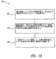
図10は、実施態様の追加または代替の一例によって電力供給システム50を運転する方法130を示す。図3の二次元アレイ68を参照して方法130を考察する。したがって、電力供給システム50は方法100に加えて、あるいは方法100に替えて方法130を使用することがある。
FIG. 10 illustrates a
工程132では、制御ロジック64は電力供給システム50からの所望の電力、電圧および電流出力の少なくとも一つを決定する。所望の値は制御ロジック64内で定められることもあり、または制御ロジック64がユーザインターフェース66を介してユーザまたはオペレータから所望の値(単数または複数)を受け取ることもある。工程134では、所望の電力、電圧および/または電流を提供するために、制御ロジック64はある数の燃料電池システム10(1,1)−10(M,N)の直列および/または並列の組合せからなる電気的な構成を決定する。工程136では、制御ロジック64はトランジスタ60(図2、一個だけ示してある)などある数の重複スイッチを操作して、燃料電池システム10(1,1)−10(M,N)のそれぞれを定められた電気的な構成で電気的に接続する。
At
上記の説明は、任意の数の燃料電池システム10を直列および/または並列の組み合わせで電気的に接続して、所望の電圧および電流で負荷12に電力を供給する組み合わせ電力供給システム50を形成することができることを示す。
The above description electrically connects any number of
燃料電池システム10は上記で考察した燃料電池システムの任意の形、たとえば図1に例示される燃料電池システム10の形をとることができる。上記で考察したように、電力供給システム50は燃料電池スタック14とそれぞれの電力貯蔵設備24との間の分極曲線の整合を利用して、燃料電池システムの直列接続を可能にする。分極曲線の整合を実現する一つの手法は、上記で一般的に考察した第一ステージ調節方式を含む。別の手法は、電力貯蔵装置24の電圧の電力貯蔵装置24の所望電圧からの変位にもとづいて、一つ以上の反応原料流の分圧を制御することを含む。また別の手法は、電力充電量の所望電力充電量からの変位にもとづいて、一つ以上の反応原料流の分圧を制御することを含む。電力充電量は、電力貯蔵装置24の充電電流/放電電流の積分によって決定することができる。その他の手法には位相またはパルススイッチング制御または制御スキームが含まれることがある。直列構成を使用する理由には、コストの有利さ、およびスタック電圧がその点における蓄電池フロート電圧に等しければ、たとえば高周波雑音問題のない24Vのシステムで効率が97%を上回ることがある、フル出力電力点で最高効率を有する直列構成が含まれる。二つのステージを有する燃料電池システム10を例示したが、いくつかの実施態様においては、電力供給システム50は第一または第二ステージのどちらかだけのステージを有する一つ以上の燃料電池システム10を組み込むことがある。
The
図11は外部負荷12に電力を供給するために運転可能なハイブリッド燃料電池システム10の別の実施態様を示す。上記で考察した実施態様とは対照的に、図11の燃料電池システム10は電力貯蔵装置24(図1)としてウルトラキャパシタ蓄電池シミュレータ回路200を使用し、ウルトラキャパシタ蓄電池シミュレータ回路200は蓄電池をシミュレーションするように構成される。
FIG. 11 shows another embodiment of a hybrid
燃料電池システム10は、たとえばプロセッサ、センサ、指示計器、バルブ、ヒータ、コンプレッサ、ファンおよび/または電磁弁などのアクチュエータなど、燃料電池システム10のさまざまな能動素子を表す内部負荷202を一つ以上含むことがある。一般にこれらの内部負荷202は「周辺システム」または「周辺機器」(BOP)と呼ばれる。内部負荷202は、電力バス19a、19bを介して燃料電池スタック14から電力を受け取るために電気的に接続される。燃料電池システム10はまた一つ以上の電流センサ204および電圧センサ206を含むことがある。
The
ウルトラキャパシタ蓄電池シミュレータ回路200は電圧バスのレール19a、19bの間に電気的に直列に接続されたある数のウルトラキャパシタC1−Cnを含む。充電電流リミッタ208をウルトラキャパシタC1−Cnと電気的に直列に接続して、ウルトラキャパシタC1−Cnへの充電電流を制限する。充電電流リミッタ208に並列にバイパスダイオードD2を電気的に接続して、充電電流リミッタ208をバイパスする放電電流にパスを提供する。たとえば他の電力貯蔵装置24またはハイブリッド燃料電池システム10と直列に接続されたとき、ウルトラキャパシタC1−Cnが逆方向に充電することを逆充電ダイオードD3が防ぐ。
Ultracapacitor
ウルトラキャパシタC1−Cnのそれぞれに並列にある数のサージダイオードDSを電気的に接続する。サージダイオードDSは充電時にウルトラキャパシタC1−Cnのそれぞれにかかる電圧を均等化し、ひいては任意のウルトラキャパシタC1−Cnにかかる電圧をウルトラキャパシタC1−Cnのサージ定格に制限することがある。たとえば、一般的なウルトラキャパシタC1−Cnは動作電圧約2.5ボルトを有することがある。例示するように、ウルトラキャパシタC1−Cnを直列に接続してより高い動作電圧を実現することがある。したがって、たとえばそれぞれのウルトラキャパシタC1−Cnに電気的に並列に接続された四つのサージダイオードDSは、それぞれのウルトラキャパシタC1−Cnにかかる電圧をウルトラキャパシタC1−Cnの一般的なサージ定格である約2.8ボルトに制限することがある。 Electrically connecting a surge diode D S of the number in parallel with each ultracapacitors C 1 -C n. Surge diode D S is equalize the voltage applied to each of the ultracapacitor C 1 -C n during charging limits the turn voltage according to any of the ultracapacitor C 1 -C n the surge rating ultracapacitors C 1 -C n Sometimes. For example, a typical ultracapacitor C 1 -C n may have an operating voltage of about 2.5 volts. As illustrated, there is possible to achieve a higher operating voltage by connecting ultracapacitors C 1 -C n in series. Thus, four surge diode D S, for example connected electrically in parallel to each ultracapacitors C 1 -C n is voltage ultracapacitor C 1 -C n according to each ultracapacitors C 1 -C n May be limited to a typical surge rating of about 2.8 volts.
キャパシタバンク(すなわち、直列接続ウルトラキャパシタ)の電圧が、ウルトラキャパシタC1−Cnのすべてが電圧が約2.8ボルトを有する点を上回り、すべてのサージダイオードDSがオンになると、電流リミッタ208の電圧降下が増大して、サージダイオードDS中を通る電流を制限し、短絡を防ぐようにバイパスダイオードD2を選ぶ。
Capacitor bank (i.e., serially connected ultracapacitor) voltage of, all the ultracapacitors C 1 -C n exceeds the point having a voltage of about 2.8 volts, when all surge diode D S is turned on,
図11は、ウルトラキャパシタC1−Cnの列の一端に配置された充電電流リミッタ208およびバイパスダイオードD2を示す。図12は、ウルトラキャパシタC1−Cnの列の他端に配置された充電電流リミッタ208およびバイパスダイオードD2を示す。図13は、ウルトラキャパシタC1−Cnの列の両端の中間に配置された充電電流リミッタ208およびバイパスダイオードD2を示す。したがって、充電電流リミッタ208およびバイパスダイオードD2をウルトラキャパシタC1−Cnの列のどちらかの端または任意の場所に配置してもよいことが明らかである。
Figure 11 shows a charging
図14は、充電電流リミッタ208の一つの実施態様をリニアモード充電電流リミッタの形で示す。充電電流リミッタ208は充電電流制限トランジスタQ1、フィードバックトランジスタQ2、第一の抵抗R1、第二の抵抗R2およびツェナーダイオードD4を含む。充電電流制限トランジスタQ1は一対のアクティブ端子(たとえば、コレクタおよびエミッタ)および制御端子(たとえば、ベース)を含み、アクティブ端子はウルトラキャパシタC1−Cnと電気的に直列に接続される。フィードバックトランジスタQ2は一対のアクティブ端子(たとえば、コレクタおよびエミッタ)および制御端子(たとえば、ベース)を含み、アクティブ端子はレール19a、19bの間に電気的に接続され、制御端子は充電電流制限トランジスタQ1のエミッタに電気的に接続される。第一の抵抗R1はフィードバックトランジスタQ2の制御端子と電圧バスの一方のレール19bとの間に電気的に接続される。第二の抵抗R2およびツェナーダイオードD4は、充電電流制限トランジスタQ1の制御端子と電圧バスの他方のレール19aとの間に電気的に接続される。
FIG. 14 illustrates one embodiment of the charge
使用時に端子電圧V1−V0が定められたしきい値電圧より高いと、リニアモード充電電流リミッタ208は充電電流を通す。ウルトラキャパシタ蓄電池シミュレータ回路200の端子にツェナーダイオードD4のツェナー電圧と充電電流制限トランジスタQ1をオンにするために必要な電圧との合計より高い電圧(たとえば約0.7ボルト)が印加されると、充電電流制限トランジスタQ1の制御端子に電流が流れ込み始める。これによって充電電流制限トランジスタQ1のコレクタに電流が流れ込み、ウルトラキャパシタC1−Cnのバンクに充電し始める。充電電流制限トランジスタQ1のエミッタからの電流が十分に大きく、第一の抵抗R1に約0.7ボルトが印加されると、フィードバックトランジスタQ2がオンになり始める。これによって、充電電流制限トランジスタQ1を通る電流が減少する。こうして、ウルトラキャパシタC1−Cnのバンク充電電流は約0.7ボルトを第一の抵抗R1の抵抗値で割った値に限定される。たとえば、第一の抵抗R1が約0.175オームなら充電電流は約4アンペアに制限されることになる。
When the terminal voltage V 1 -V 0 is higher than a predetermined threshold voltage during use, the linear mode charging
図14の回路構成はまた、電荷を貯蔵するとき(すなわち、非フロート充電時)、ウルトラキャパシタC1−Cnから流れ出る電流を最小にする。ウルトラキャパシタ蓄電池シミュレータ回路200の端子に、ツェナーダイオードD4のツェナー電圧(たとえば約24ボルト)と充電電流制限トランジスタQ1をオンするために必要な電圧(たとえば約0.7ボルト)との合計より低い電圧が印加されると、ウルトラキャパシタC1−Cnからの電流はまったく流れず、その結果ウルトラキャパシタC1−Cnは比較的長い時間電荷を維持する。
The circuit configuration of FIG. 14 also minimizes the current flowing out of the ultracapacitors C 1 -C n when storing charge (ie, during non-float charging). The terminal of the ultracapacitor
図15は充電電流リミッタ208の別の実施態様を示し、図14の実施態様にダーリントン回路構成Q3で接続された一対のトランジスタ、一対の抵抗およびダイオードを加える。ダーリントン回路Q3は充電電流制限トランジスタQ1のベースとツェナーダイオードD4との間に電気的に接続され、第二の抵抗R2およびツェナーダイオードD4中を流れる電流ID3を低下させる。図15の構成は、図14の実施態様より若干複雑ではあるが、第二の抵抗R2およびツェナーダイオードD3によって失われる電力を減らす。
Figure 15 shows an alternative embodiment of the charging
図16は充電電流リミッタ208のまた別の実施態様を示し、図15の実施態様に過電圧状況で充電電流を遮断するする過電圧回路を加える。過電圧回路は過電圧トランジスタQ4、過電圧ツェナーダイオードD5および過電圧抵抗R3を含む。過電圧トランジスタQ4およびフィードバックトランジスタQ2のエミッタは共通接続され、過電圧トランジスタQ4およびフィードバックトランジスタQ2のコレクタもまた共通接続される。過電圧ツェナーダイオードD5および過電圧抵抗R3は過電圧トランジスタQ4のベースと電圧バスの一方のレールとの間に電気的に接続される。
FIG. 16 shows yet another embodiment of the charge
ウルトラキャパシタC1−Cnのバンクの端子電圧がツェナーダイオードD5のツェナー電圧(たとえば約30ボルト)と過電圧トランジスタQ4をオンにするために必要な電圧(たとえば約0.7ボルト)との合計を上回ると、過電圧トランジスタQ4はフィードバックトランジスタQ2および充電電流制限トランジスタQ1をともにオフにし、したがって充電電流がそれ以上ウルトラキャパシタC1−Cnに流入することを防ぐ。過電圧遮断は蓄電池に固有の特長でないが、ハイブリッド燃料電池システムでは、無負荷条件(たとえば、開路電圧すなわちOCV)での燃料電池スタック14の電圧上昇を克服するために望ましい。図16の実施態様にはまた、充電電流制限トランジスタQ1によって発生する熱、ひいては任意の関連するヒートシンクのサイズを制限するという特長がある。
The terminal voltage of the bank of ultracapacitors C 1 -C n is between the Zener voltage of Zener diode D 5 (eg, about 30 volts) and the voltage required to turn on overvoltage transistor Q 4 (eg, about 0.7 volts). above the sum prevents overvoltage transistor Q 4 are the feedback transistor Q 2 and the charging current limiting transistor Q 1 together off, thus the charging current flows into the more ultracapacitors C 1 -C n. Although overvoltage interruption is not an inherent feature of a storage battery, it is desirable in a hybrid fuel cell system to overcome the voltage rise of the
図17は、充電電流リミッタ208のさらにまた別の実施態様を示し、ウルトラキャパシタC1−Cnのバンクが所望の電圧に達すると充電電流をカットオフする回路を図16の実施態様に加える。この回路は電圧設定トランジスタQ5、電圧設定ツェナーダイオードD6、および電圧設定抵抗R4を含む。電圧設定トランジスタQ5のアクティブ端子は過電圧トランジスタQ4のベースと電圧バスのレールとの間に電気的に接続される。電圧設定ツェナーダイオードD6および電圧設定抵抗R4は電圧設定トランジスタQ5のベースとウルトラキャパシタC1−Cnのバンクとの間に電気的に接続される。図17の実施態様には充電電流制限トランジスタQ1によって発生される熱、ひいては関連する任意のヒートシンクのサイズを制限するという特長がある。図17の実施態様はまた、電力を節約し全体的なシステム効率を改善する。
Figure 17 shows a still further embodiment of the charging
図11−17の実施態様は既に考察した概念と同等であり、補完的であり、任意のものが「自力起動方法および燃料電池電源設備用の装置、および自力起動能力を有する燃料電池電源設備(BLACK START METHOD AND APPARATUS FOR A FUEL CELL POWER PLANT, AND FUEL CELL POWER PLANT WITH BLACK START CAPABILITY)」と題する2003年3月12日出願の係属中の米国特許出願第10/388191号(代理人提出文書第130109.483号)明細書中で考察される自力起動法とともに使用されることもある。 The embodiment of FIGS. 11-17 is equivalent to the previously discussed concept, is complementary, and any of the “self-starting method and apparatus for fuel cell power supply and fuel cell power supply with self-starting capability ( US Patent Application No. 91/38, pending US patent application No. 10/38, filed March 12, 2003 entitled "BLACK START METHOD AND APPARATUS FOR A FUEL CELL POWER PLANT, AND FUEL CELL POWER PLANT WITH BLACK START CAPABILITY" 130109.483) and may be used with the self-starting method discussed in the specification.
図11−17の実施態様では、燃料電池システム10は二モード電源装置として動作する。出力は二つの設定値、すなわち、1)出力電流限界値、および2)出力電圧限界値によって制御される。負荷抵抗が十分高く出力電流限界より小さな電流が流れるとき、燃料電池システム10は出力電圧限界を設定する定電圧電源として動作する。負荷抵抗が十分低く出力電圧限界設定点における出力電流制限より大きな電流が流れるとき、燃料電池システム10は出力電流限界に設定された定電流電源として動作する。充電電流限界の設定は、図1を参照して考察した蓄電池充電電流リミットモードの直列パス素子32(図1)によってではなく、ウルトラキャパシタ蓄電池シミュレータ回路200によって処理される。電力貯蔵装置がウルトラキャパシタではなく蓄電池を含む場合でさえも、その他の電力貯蔵装置回路中に充電電流限界を組み込むと、これによって、たとえば充電された蓄電池を有するシステムに壊れたまたは放電した蓄電池を接続してしまったとき電流の急激な流入を防ぐはずなので有利である。
In the embodiment of FIGS. 11-17, the
バラードネクサTM(Ballard NexaTM)燃料電池スタックを使用する燃料電池システム10の場合、出力電圧限界は燃料電池スタック14の開路電圧(OCV、たとえば約54.8ボルト)以下に設定され、出力電流リミットは燃料電池スタック電流限界および燃料電池システムの熱的限界を上回らないように設定される。たとえば出力電力限界が1.3kWなら、出力電流リミットは約23.7アンペアとなる。
For Ballard Nexa TM (Ballard Nexa TM)
ウルトラキャパシタ蓄電池シミュレータ回路200は直直流変換器として動作する。一般に周辺機器202(図11)はスタック電圧から直接にではなく、ウルトラキャパシタ蓄電池シミュレータ回路200の出力からの直流24ボルトで運転される。
The ultracapacitor
ウルトラキャパシタ蓄電池シミュレータ回路200は入力電圧範囲55ボルト(OCV)から25.5ボルト(フル負荷)を有する。入力電圧(すなわちスタック電圧)が25.5ボルトより低くなると、ウルトラキャパシタ蓄電池シミュレータ回路200が入力電圧がそれ以上低下しないところまでその出力電流限界を下げる。入力電流(すなわちスタック電流)が48アンペアに上がると、ウルトラキャパシタ蓄電池シミュレータ回路200は入力電流がそれ以上大きくならないように出力電流限界を小さくする。
The ultracapacitor
図18は、実施態様の一例に従ってウルトラキャパシタ蓄電池シミュレータ回路200を使用して燃料電池システム10を運転する方法300を示す。工程302では、たとえば燃料電池スタック14から充電電流が供給される。工程304では、充電電流制限トランジスタQ1およびフィードバックトランジスタQ2がウルトラキャパシタC1−Cnに供給される充電電流を充電電流限界しきい値未満に制限する。工程306では、サージダイオードDSが各ウルトラキャパシタC1−Cnにかかる電圧を制限する。工程308では、過電圧条件の場合に過電圧トランジスタQ4がウルトラキャパシタC1−Cnへの充電電流の供給を停止する。工程310では、ウルトラキャパシタC1−Cnのバンクにかかる所望の電圧が達成されると、電圧設定トランジスタQ5がウルトラキャパシタC1−Cnへの充電電流の供給を停止する。工程312では、ウルトラキャパシタC1−Cnが充電電流リミッタ208をバイパスし、バイパスダイオードD2を介して放電する。
FIG. 18 illustrates a
図19は、直流バスのレール556a、556bを介して負荷12に電力を供給する電力システム500を示す。電力システム500は、一般に三相交流電力の形で送電網502から電力を受け入れる。電力システム500は送電網502から交流電力を受け入れ、電力を整流する一つ以上の整流器アレイ504(1)−504(n)を含む。整流された電力は直流バス556a、556bを介して負荷12に供給される。整流器504(1)−504(n)のアレイは負荷12に連続的に電力を供給し、さまざまな電力貯蔵装置24を再充電する直流電力の主供給源として動作する。
FIG. 19 shows a
電力システム500は一つ以上の燃料電池ハイブリッドモジュール510(1)−510(n)の配列を含む。燃料電池ハイブリッドモジュール510(1)−510(n)のアレイは、たとえば送電網502の停電の場合には、直流バス556a、556bを通して負荷12に連続的な予備電力を提供する。
The
電力システム500はまた負荷ブリッジングおよびサージ(すなわち需要)電力供給用エネルギーを貯蔵する一つ以上のウルトラキャパシタ蓄電池シミュレータ200(1)−200(n)のアレイを含むことがある。さらに、またはあるいは、電力システム500は負荷ブリッジングおよびサージ電力供給用エネルギーを貯蔵するはずみ車蓄電池シミュレータ506を含むことがある。はずみ車蓄電池シミュレータ506はウルトラキャパシタ蓄電池シミュレータ200について説明したものと類似の回路を使用することがある。さらに、またはあるいは、電力システム500は負荷ブリッジングおよびサージ電力提供用のエネルギーを貯蔵する一つ以上の充電式蓄電池508を含むことがある。これらの電力貯蔵装置はレール556a、556bによって形成される直流バスを介して負荷12に電力を供給することがある。
The
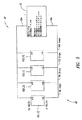
図20は図19の電力システム500中での使用に適する燃料電池ハイブリッドモジュールアレイ510を示す。燃料電池ハイブリッドモジュールアレイ510は、電気的に直列に接続された第一および第二の燃料電池スタック14、および関連周辺機器202、調節装置517(たとえば、図1および11の直列パス素子32および調節回路34)およびウルトラキャパシタ蓄電池シミュレータアレイ200を含む。燃料電池ハイブリッドモジュールアレイ510はまた、ウルトラキャパシタ蓄電池シミュレータ200(1)−200(n)、はずみ車蓄電池シミュレータ506、または図19の充電式蓄電池508などの電力貯蔵装置509を含むことがある。ウルトラキャパシタ蓄電池シミュレータアレイ200は、負荷の要求に応じてすばやく電流を供給および吸収して燃料電池ハイブリッドモジュールのための動的応答を提供し、一方スタック14および周辺機器202はこれより低速の応答をする。電力貯蔵装置509は、負荷ブリッジングおよびサージ電力供給用エネルギーを提供する。この構成によって、蓄電池シミュレータアレイ200が負荷ブリッジングおよびサージ容量も担当すれば必要になるウルトラキャパシタよりも、少ない数のウルトラキャパシタの使用で済むことがある。いくつかの実施態様では、これがまた、電源設備中で使用されるウルトラキャパシタ数の全体的な削減をもたらすことがある。
FIG. 20 shows a fuel cell
中央バス556aから水素供給用の電磁弁210などの補助的な装置(または換気ファンまたはフロースイッチ(図示していない))に電力を供給することができる。負荷をバランスさせて基準を提供することによってシステム始動を助けるために、一つ以上のイコライザ回路が使用されることがある。イコライザ回路はバス556a、556bおよび556cの間の抵抗器212の列の形をとることがある。望むなら、特定の電圧レベルを維持するために負荷を共有するアクティブコントローラなど、中央バス556a上で負荷をバランスさせるその他の能動または受動手段もまた使用することがある。
Power can be supplied from the
図21は、数M行および数N列に配置されて電力システムを形成し、電力バス456a、456bを介して一つ以上の負荷12に電力を供給する燃料電池システム10の二次元アレイ468を示す。燃料電池システム10は10(1,1)−10(M,N)で個別参照され、括弧内の第一の数は二次元アレイ468中の燃料システム10の行位置を示し、括弧内の第二の数は列位置を示す。図21の楕円記号は二次元アレイ468のさまざまな行および列には別の燃料電池システム(明示的には示していない)が含まれることがあることを示す。例示されてはいないが、燃料電池システム10のその他の多次元アレイ、たとえば燃料電池システム10の三次元アレイもまた可能である。
FIG. 21 illustrates a two-
図21の二次元アレイ468は図3の二次元アレイに類似しているが、行(たとえば10(3,1)、10(3,2)、10(3,3),...10(3,N))を形成する燃料電池システム10を電気的に接続して、少なくともN+1個の重複を提供するリンク490を含む。二次元アレイ468は、既に述べた実施態様のダイオード58、故障および重複スイッチ60、62およびその他の素子を省略することがある。リンク490は重複性を提供し、一つの燃料電池システム10の不良によって電圧の並び(列)全体が不良となることを防ぐ。たとえば、リンク490がなければ、燃料電池システム10(2,1)が不良になると、燃料電池システム10(1,1)、10(3,1)から10(M,1)までが利用できなくなるであろう。リンク490は、列中の任意の個別の燃料電池システム10の不良によって、負荷12に全電力を供給する能力が損なわれることを防止する。下記で考察するように、電圧バスのレール上に所望の電位を発生させるために、リンク490がタップされるかまたはタップを形成することがある。
21 is similar to the two-dimensional array of FIG. 3, but with rows (eg, 10 (3,1), 10 (3,2), 10 (3,3),. 3, N)) is electrically connected to include a
図22は、複数の電圧レベルに少なくともN+1個の重複を提供できる二次元アレイ468の実施態様を示す。燃料電池システムの第二列10(1,2)、10(2,2)、10(3,2)...10(M,2)はタップまたはレール456b、456cによる電圧バス形を介して第一の負荷12aにM×24ボルトで40アンペアを供給することができる。燃料電池システムの第三列10(1,3)、10(2,3)はタップまたはレール456b、456cによって形成された第二の電圧バスを介して第二の負荷12bに48ボルトで40アンペアを供給することができる。燃料電池システムの第三列10(1,4)はタップまたはレール456b、456dによって形成された電圧バスを介して第三の負荷12cに24ボルトで40アンペアを供給することができる。負荷が電流をさらに必要とするなら、対応する電圧バスのレールの間に燃料電池システム10の別の列を加えることができる。したがって例示するシステムでは、アレイ468に燃料電池システム10を加えることによって、40アンペアの倍数で電流を増やすことができる。
FIG. 22 shows an embodiment of a two-
燃料電池システムの第一列10(1,1)、10(2,1)、10(3,1)...10(M,1)は二次元アレイ468中のその他の燃料電池システム10のそれぞれに対して重複性を提供する。第一列の燃料電池システム10の数は、アレイ469の最大の列中の燃料電池システム10の数と等しく、少なくともN+1個の重複性を保証する。燃料電池システムの一つの列10(1,1)−10(M,1)を使用することによって、その他の列のそれぞれに対して各列に特定の燃料電池システムを提供する必要なしに重複性が提供される。これによって先に説明した実施態様中におけるよりも少ない燃料電池システム10で望ましい少なくともN+1個の重複性が実現される。
First row of fuel cell systems 10 (1,1), 10 (2,1), 10 (3,1). . . 10 (M, 1) provides redundancy for each of the other
図23は、複数の二極性の電圧レベルへの重複性の提供に適する燃料電池システム10の二次元アレイ468の別の実施態様を例示する。燃料システムの第二列10(−2,2)、10(−1,2)、10(1,2)、10(2,2)、10(3,2)、10(4,2)、10(5,2)はタップまたはレール456a、456bによって形成された電圧バスを介して第一の負荷12aに120ボルトで40アンペアを供給することができる。燃料電池システムの第三列10(−2,3)、10(−1,3)、10(1,3)、10(2,3)は、タップまたはレール456a、456cによって形成された電圧バスを介して第二の負荷12bに+48ボルトで40アンペアを供給するか、またはタップまたはレール456a、456dによって形成された電圧バスを介して第三の負荷12cに−48ボルトで40アンペアを供給することができる。燃料電池システムの第四列10(−1,4)、10(1,4)はタップまたはレール456a、456eによって形成された電圧バスを介して第四の負荷12dに+24ボルトで40アンペアを供給するか、またはタップまたはレール456a、456fによって形成された電圧バスを介して第五の負荷12eに−24ボルトで40アンペアを供給することができる。ここでも、燃料電池システムの第一列10(−2,1)、10(−1,1)、10(1,1)、10(2,1)、10(3,1)、10(4,1)、10(5,1)はアレイ468中のその他のすべての燃料電池システム10に少なくともN+1個の重複性を提供する。
FIG. 23 illustrates another embodiment of a two-
例示されてはいないが、アレイ468が一つ以上のイコライザ回路を使用して、負荷をバランスさせて基準を提供することによって、システム始動を助けることがある。イコライザ回路は上記で図20に関連して説明したもののようでもよい。燃料電池システム10がウルトラキャパシタを使用する場合には、中間バスのソースインピーダンス(硬さ)を改善するために、たとえば、任意の数の直列接続燃料電池システム10にかかる中間電圧用のイコライザ装置が加えられることがある。
Although not illustrated, the
図23の実施態様は、一般にパーソナルコミュニケーションサービス(PCS)およびマイクロ波中継ステーションなどの無線通信用に24ボルト、回線(通信回線)経由の従来通信用に48ボルト、および交換操作およびサブステーション用に直流120ボルトを使用する電話交換局など、電話関連用途の電力調整および/または電力バックアップの提供にとくに適している。 The embodiment of FIG. 23 is generally 24 volts for wireless communications such as personal communication services (PCS) and microwave relay stations, 48 volts for conventional communications over lines (communication lines), and for switching operations and substations. It is particularly suitable for providing power regulation and / or power backup for telephone related applications, such as telephone exchanges using 120 volts DC.
図24および25は従来のバックアップシステムまたは無停電電源装置の系統図である。図24では、通常は送電網502が整流器504および照明、HVACおよびその他の装置など、その他の交流負荷に電力を供給する。整流器504は送電網からの交流電力を直流電力に変換し、直流電力配電盤512に送る。配電盤512から適当な電圧直流負荷に電力を直接供給することがある。電力はまた直直流変換器514に送られ異なる電圧に変換されてその他のDC負荷に使用されるか、または電力はインバータ516に送られ交流電源に変換されて交流負荷に使用される。送電網が停電すると蓄電池バンク518によって配電盤512に電力を供給する。蓄電池バンク518の規模は所望の時間、重要な負荷に十分な電力を提供するよう設定される。送電網が長期間にわたって停電すると、スイッチ152によって待機発電機520を接続して電力を提供する。
24 and 25 are system diagrams of a conventional backup system or uninterruptible power supply. In FIG. 24,
図25では、通常は送電網からの電力が交流電力配電盤512から交流負荷へ直接、整流器156経由で直流−48ボルトへ、および/または交流/直流コンバータ158経由でその他の直流負荷へ供給される。送電網が停電すると、蓄電池バンク518によってインバータ154に電力が供給され、インバータが直流電源を交流電源に変換する。図24と同じように、送電網が長期間にわたって停電すると待機電源設備520が接続されて電力を提供する。
In FIG. 25, power from the power grid is typically supplied directly from the AC
図26−29は従来のVRLA電力供給システムおよび本電源設備の実施態様の系統図である。 26-29 is a system diagram of an embodiment of a conventional VRLA power supply system and the present power supply facility.
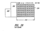
図26および27に例示されたシステムは400アンペア/直流48ボルトで4時間電力を供給することができる(400アンペア4時間バックアップ)。図26では、通常は送電網が整流器504を介して負荷に電力を供給する。送電網が停電すると、蓄電池バンク518中のVRLA蓄電池530が負荷に電力を供給する。送電網が回復したら、送電網が整流器532に電力を供給して蓄電池バンク518を再充電する。
The system illustrated in FIGS. 26 and 27 can supply power for 4 hours at 400 amps / 48 volts DC (400
図27の実施態様は400アンペア/直流48ボルトの電力を供給するように構成された燃料電池システム10のアレイ468を含む。アレイ468は、燃料電池二つのシステムを十組有する。各組の二つの燃料電池システムは電気的に直列に接続され、各組は電気的に互いに並列に接続される。各燃料電池システム10は24ボルトおよび40アンペアで1kWを発生し、二つの直流12ボルトVRLA蓄電池と電気的に並列に接続された47セルPEM燃料電池スタックを含む。送電網電力が停電すると、水素供給源540からの水素が供給ライン542を経由してアレイ468の燃料電池に供給され、適切な空気供給源(示していない)から燃料電池に空気も供給される。アレイ468によって発生した電力が負荷に供給される。送電網電力が回復したら、望むなら送電網電力が整流器504に電力を供給して燃料電池システム10の蓄電池を再充電する。図27では、水素供給源540は100ガロン(380リットル)、3600ポンド/平方インチ(25メガパスカル)の水素タンクであり、アレイ468が負荷に連続して4時間電力を供給するために十分な水素を保持する。
The embodiment of FIG. 27 includes an
図26および27の400アンペア4時間システムの寸法、重量および設置床面積を表1にまとめる。蓄電池バンク518のサイズおよび重量は現在利用できるVRLA蓄電池バンクにもとづいている。比較に使用した蓄電池バンク定格は10倍再充電レートにもとづき、定電流負荷を仮定している。整流器定格は負荷電流プラス0.1C蓄電池充電電流にもとづいている。前面クリアランスは安全規制によって必要とされる隣接の壁と電源装置の背面および側面との間の面積を指す。
Table 1 summarizes the dimensions, weight, and floor space of the 400

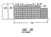
図28および29の400アンペア8時間システムの寸法、重量および設置面積を表2に要約する。比較データは表1のデータの場合になされたと同じ仮定にもとづいている。 The dimensions, weight and footprint of the 400 amp 8 hour system of FIGS. 28 and 29 are summarized in Table 2. The comparison data is based on the same assumptions made for the data in Table 1.
表1および2に示すように、VRLA蓄電池を組み込んだ本電源設備の実施態様でさえも現行のVRLA蓄電池系電源装置に関連するコストおよび潜在的な環境責任を著しく減少させる。たとえば、図27の電源装置は図26の従来システムより95.4%少ない蓄電池を必要とする。図28と図29との電源装置の間では、使用されるVRLA蓄電池の数に97.4%の削減がある。もちろん、本電源装置のその他の実施態様においては、VRLA蓄電池を完全に除いてもよい。 As shown in Tables 1 and 2, even embodiments of the present power supply facility incorporating VRLA accumulators significantly reduce the cost and potential environmental responsibility associated with current VRLA accumulator power supplies. For example, the power supply device of FIG. 27 requires 95.4% fewer storage batteries than the conventional system of FIG. Between the power supply of FIG. 28 and FIG. 29, there is a 97.4% reduction in the number of VRLA batteries used. Of course, in other embodiments of the power supply apparatus, the VRLA storage battery may be completely removed.
表1および2はまた、従来のVRLA蓄電池系電源装置と比較して、本電源装置の重量および設置面積の削減を示す。図27および29の実施態様は、従来のシステムと比較して、それぞれ19.9ft2(1.9m2)および57.9ft2(5.4m2)の面積削減を表す。電源装置を設置するコストが650,000米ドル/ft2以上にも達することがある多くの現場用途の場合に、本電源設備の設置面積の小ささだけでもかなりのコスト削減を提供することができる。従来の電源装置と比較して、本電源設備の実施態様のために必要な整流器のサイズおよび設置面積がより小さいことによって、さらにコスト削減を実現することができる。 Tables 1 and 2 also show the weight and footprint savings of the power supply compared to a conventional VRLA storage battery power supply. Embodiment of FIGS. 27 and 29, as compared to conventional systems, represent the area reduction, respectively 19.9ft 2 (1.9m 2) and 57.9ft 2 (5.4m 2). For many field applications where the cost of installing a power supply can reach US $ 650,000 / ft 2 or more, even a small installation area of the power supply can provide significant cost savings. . Compared with the conventional power supply apparatus, the cost reduction can be further realized by the smaller size and installation area of the rectifier required for the embodiment of the power supply equipment.
表1および2のデータは図27および29の電源設備に関連する水素貯蔵装置の寸法および設置面積を考慮していない。これは水素貯蔵装置が電源設備の他の部分と同じ場所にある必要はないからである。従来の電源装置では、蓄電池がエネルギー貯蔵装置および電力供給源である。実際問題として、電源から遠くなるにつれて直流システムの電力損失が劇的に増大するので、蓄電池バンクは配電盤および/または負荷の近くになければならない。本電源設備では、エネルギー貯蔵装置は電源装置から切り離されているので、水素貯蔵装置は燃料電池アレイから任意の所望の距離を置いて配置されてよい。したがって、水素貯蔵装置は本電源設備のその他の部分とともに屋内に置く必要はなく、それゆえ設置面積の計算に水素貯蔵設備を含める必要もない。 The data in Tables 1 and 2 does not take into account the dimensions and footprint of the hydrogen storage device associated with the power supply installations of FIGS. This is because the hydrogen storage device need not be in the same location as the rest of the power supply. In a conventional power supply device, a storage battery is an energy storage device and a power supply source. As a practical matter, the battery bank must be close to the switchboard and / or load because the power loss of the DC system increases dramatically as the distance from the power source increases. In the present power supply facility, since the energy storage device is disconnected from the power supply device, the hydrogen storage device may be arranged at any desired distance from the fuel cell array. Therefore, the hydrogen storage device does not need to be placed indoors with the rest of the power supply facility, and therefore it is not necessary to include the hydrogen storage facility in the installation area calculation.
本電源設備中のエネルギー貯蔵装置と電源装置との切り離しによって、現行の蓄電池システムに対して著しい特長を提供することができる。水素貯蔵装置はたとえば戸外、別棟または地下施設に配置することができる。ある種のテレコム用途では、たとえば通信装置は多くの場合建物の屋根に配置される。ほとんどの建築規則ではVRLA蓄電池バンクを屋上に設置することは許されておらず、バックアップ電源装置は装置からある程度距離をおいて設置されなければならない。前述のように、この配置によって蓄電池から負荷(単数または複数)への電力の供給でかなりの電力損失が起こる。これに対して、本電源設備を用いれば燃料電池アレイはその設置荷重が小さいので、屋根上に設置することができ、装置から任意の距離に配置した水素貯蔵装置から電力損失を伴わずに水素を供給することができる可能性がある。 By separating the energy storage device and the power supply device in the power supply facility, significant features can be provided to the current storage battery system. The hydrogen storage device can be placed, for example, outdoors, in a separate building, or in an underground facility. In certain telecom applications, for example, communication devices are often located on the roof of a building. Most building rules do not allow the VRLA battery bank to be installed on the roof, and the backup power supply must be installed some distance from the device. As mentioned above, this arrangement results in significant power loss in the supply of power from the storage battery to the load (s). On the other hand, if this power supply equipment is used, the installation load of the fuel cell array is small, so that it can be installed on the roof, and the hydrogen storage device placed at an arbitrary distance from the device can generate hydrogen without power loss. May be able to supply.
さらに、水素貯蔵装置のために低コストの地下施設を用いることができる。実際、たとえば燃料電池アレイを設置した施設の近くに水素タンクを埋設するだけでよいことがある。これは水素が地下水を汚染せず、リークしても土壌から浸み出すからである。水素が地下水を汚染しないという事実は、ディーゼルまたはその他の燃料タンク用に必要とされるような高価な封じ込め槽が必要ないことを意味する。したがって、水素貯蔵装置はその他のオプションよりもコストが低く環境にやさしくなり得る。 In addition, low cost underground facilities can be used for the hydrogen storage device. In fact, it may only be necessary to embed a hydrogen tank near the facility where the fuel cell array is installed, for example. This is because hydrogen does not pollute the groundwater and will leak out of the soil if it leaks. The fact that hydrogen does not contaminate groundwater means that expensive containment tanks such as those required for diesel or other fuel tanks are not required. Thus, the hydrogen storage device can be less costly and environmentally friendly than other options.
実は、図26または28に示すような従来の電源装置は、蓄電池バンクを適当な大きさの燃料電池アレイおよび水素貯蔵装置で置き換えることによって、本電源装置の実施態様にアップグレードすることができる。蓄電池を再充電するために使用される既存の整流器を取り除いてもよく、または電源装置の出力を増大するために用いてもよい。たとえば図26の従来型の400アンペア4時間バックアップ電源装置を見てみよう。本電源設備の燃料電池アレイ468は再充電用に整流器532を必要としないので、望むなら二つの整流器504は負荷に電力を供給するために使用してもよい。したがって、図26の電源設備を800アンペア電源装置にアップグレードすることができる。さらに、水素貯蔵装置の容量を適切に選ぶことによって、アップグレードされたシステムは4−8時間またはそれ以上にわたってバックアップ電力を供給することができる。同時に、アップグレードされたシステムはより小さな設置面積を有する。
In fact, a conventional power supply as shown in FIG. 26 or 28 can be upgraded to an embodiment of the power supply by replacing the battery bank with an appropriately sized fuel cell array and hydrogen storage device. Existing rectifiers used to recharge the storage battery may be removed or used to increase the output of the power supply. For example, consider the conventional 400
実施態様の例を直流−48ボルトシステムとして説明したが、本電源設備はそのようなシステムに限定されない。たとえば、図23のアレイ468のように24、48および120ボルトで直流電力を供給するように本電源設備を構成してもよく、あるいは任意の所望の電圧(単数または複数)の直流電力を供給するように異なる構成としてもよい。同様に、本電源設備は交流電力を供給するように構成してもよい。たとえば図27または29の整流器504をインバータで置き換えることによって、例示した実施態様は交流電力供給システムとしての使用に適するものとなる。
Although the example of embodiment was demonstrated as a DC-48 volt system, this power supply installation is not limited to such a system. For example, the power supply may be configured to supply DC power at 24, 48 and 120 volts as in
(結論)
開示した実施態様は電力供給システム構築への「ビルディングブロック」または「コンポーネント」手法を提供し、構築者が少数のあるいはただ一つの基本型の燃料電池システム10から非常に多様な電力供給システムを構築することを可能にする。この手法によって、設計、製造業者および在庫コストが削減され、末端ユーザ製品(すなわち電力システム)の平均故障間隔を結果として長くする重複性が提供される。このアプローチはまた、メンテナンスまたは修理を単純化し、それらのコストを低下させることがある。
(Conclusion)
The disclosed embodiments provide a “building block” or “component” approach to building a power supply system, where builders can build a very diverse power supply system from a few or just one basic fuel cell system 10. Make it possible to do. This approach reduces design, manufacturer and inventory costs, and provides redundancy that results in longer mean time between failures of the end user product (ie, power system). This approach may also simplify maintenance or repairs and reduce their costs.
本明細書中においては、例示を目的として電力供給システムおよび方法の特定の実施態様および実施例を説明したが、関連当業者が認識するように、本発明の精神および範囲から逸脱することなく、さまざまな同等な変更を実施することができる。たとえば、本明細書中に提供された開示は、必ずしも一般的に上記で説明したポリマー交換膜燃料電池アセンブリではなく、その他の種類の燃料電池スタック14または燃料電池アセンブリを含む燃料電池システム10に適用することができる。さらに、またはあるいは、燃料電池システム10は燃料電池スタック14の部分を蓄電池のセル、はずみ車、またはウルトラキャパシタバンク24などの電力貯蔵装置の部分と接続することができる。燃料電池システム10は反応原料分圧を調節するさまざまなその他のアプローチおよび素子を使用することがあり、あるいは分圧にかまわず運転することがある。上記で説明したさまざまな実施態様を組み合わせてまた別の実施態様を提供することができる。
While specific embodiments and examples of power supply systems and methods have been described herein for purposes of illustration, it will be appreciated by those skilled in the art without departing from the spirit and scope of the present invention. Various equivalent changes can be made. For example, the disclosure provided herein applies not only to the polymer exchange membrane fuel cell assemblies generally described above, but to other types of fuel cell stacks 14 or
一般に、本電源設備は、以下を含むが、それらには限定されない範囲の用途で、バックアップ電力またはUPSシステム中に使用される。
1.ネットワークサーバファーム ハブおよびルータなどのLAN/WAN装置。
2.通信 CATV、ラジオ、テレコミュニケーション記録システムおよび/またはサーバ、無線基地局、マイクロ波中継局、レーダ自動追跡システム。
3.コンピュータルーム 小規模および中規模サーバ、大規模企業サーバ、データ記録システム、ネットワークコンピュータクラスタ、インターネットデータセンター。
4.デスクトップ/ワークステーション スタンドアロンPC、ワークステーションおよびコンピュータ周辺機器。
5.工業/商業分野 プロセス制御装置、医療機器、実験室測定機器、交通管理システム、セキュリティ装置、販売拠点設備。
In general, the power supply equipment is used in backup power or UPS systems for a range of applications including, but not limited to:
1. Network server farm LAN / WAN devices such as hubs and routers.
2. Communication CATV, radio, telecommunications recording system and / or server, radio base station, microwave relay station, radar automatic tracking system.
3. Computer rooms Small and medium-sized servers, large-scale enterprise servers, data recording systems, network computer clusters, Internet data centers.
4). Desktop / workstation Stand-alone PC, workstation and computer peripherals.
5. Industrial / Commercial field Process control equipment, medical equipment, laboratory measurement equipment, traffic management systems, security equipment, sales base equipment.
加えて、ピーク電力または分散電力用途においても本電源設備を使用することがある。
In addition, the power supply equipment may be used in peak power or distributed power applications.
本電源設備および運転方法はVRLA蓄電池を使用する従来の電力供給システムより小さくて軽いシステムを提供する。本電源設備はまた、「ホットスワップ可能」な個々の燃料電池システムによる「瞬時オン」運転を提供する。 The power supply facility and method of operation provide a smaller and lighter system than conventional power supply systems that use VRLA batteries. The power supply also provides “instant on” operation with individual “hot swappable” fuel cell systems.
必要なら、さまざまな特許、出願および出版物のシステム、回路および概念を使用して本発明の諸様相を変更し、本発明のさらにまた別の実施態様を提供することができる。これらおよびその他の変化は、上記で詳細に行なった説明に従って本発明に対してなされる。一般に以下の請求項では、使用する用語は、本発明を請求された明細書中で開示した特定の実施態様に限定すると解釈されるべきではなく、請求項に従って動作するすべての燃料電池システムを含むと解釈されるべきである。したがって、本発明は本開示によって限定されず、本発明の範囲は以下の請求項によってのみ決定されるべきものである。 If desired, various patent, application and publication systems, circuits and concepts can be used to modify aspects of the invention and provide yet other embodiments of the invention. These and other changes are made to the invention in accordance with the detailed description given above. In general, in the following claims, the terms used should not be construed to limit the invention to the specific embodiments disclosed in the claimed specification, but include all fuel cell systems that operate according to the claims. Should be interpreted. Accordingly, the invention is not limited by the disclosure, but the scope of the invention is to be determined only by the following claims.
Claims (53)
電力バス、
第一および第二の燃料電池システムであって、燃料電池スタック、燃料電池スタックと電気的に並列に接続された電力貯蔵装置、および燃料電池スタックから電力貯蔵装置および電力バスへの電流の流れを制御する手段をそれぞれ含む燃料電池システム、および
少なくとも二つの燃料電池システムを電力バス中に選択的に電気的に直列に接続する手段
を含むアレイを備える電源設備。 An array of fuel cell systems,
Power bus,
First and second fuel cell systems, comprising: a fuel cell stack; a power storage device electrically connected in parallel with the fuel cell stack; and a current flow from the fuel cell stack to the power storage device and a power bus. A fuel cell system, each comprising means for controlling, and a power supply comprising an array comprising means for selectively electrically connecting at least two fuel cell systems in a power bus in series.
電力バス、
電力バスに電気的に直列に接続可能な複数の燃料電池システムであって、それぞれ燃料電池スタックを含む燃料電池システム、
少なくとも一つの燃料電池スタックと電気的に並列に接続された電力貯蔵装置、および
複数の燃料電池システムのそれぞれ第一の燃料電池システムを電力バスに選択的に電気的に直列に接続する重複手段であって、複数の燃料電池のそれぞれ第一の燃料電池の運転条件と異なる運転条件に感応する第一の重複手段
を含むアレイを備える電源設備。 An array of fuel cell systems,
Power bus,
A plurality of fuel cell systems electrically connectable in series to a power bus, each comprising a fuel cell stack;
A power storage device electrically connected in parallel with at least one fuel cell stack, and overlapping means for selectively electrically connecting the first fuel cell system of each of the plurality of fuel cell systems to the power bus in series A power supply facility comprising an array including first overlapping means that is sensitive to an operating condition different from the operating condition of each of the plurality of fuel cells.
電力バス、
互いに電気的に直列に接続され、そこに第一の電圧を発生するために運転可能な第一の燃料電池システムの集合、
互いに電気的に直列に接続され、そこに電圧を発生するために運転可能な第二の燃料電池システムの集合であって、第二の燃料電池システムの集合の各燃料電池システムが第一の燃料電池システムの集合の各燃料電池システムにそれぞれ電気的に並列に接続され、各燃料電池システムが燃料電池スタック、燃料電池スタックと電気的に並列に接続されたウルトラキャパシタ、燃料電池スタックからウルトラキャパシタへの充電電流を制限するために電気的に接続された充電電流リミッタ、および充電電流リミッタをバイパスしてウルトラキャパシタからの放電パスを提供するために電気的に接続された充電電流リミッタバイパス素子を含む燃料電池システムの組
を含むアレイを備える電源設備。 An array of fuel cell systems,
Power bus,
A first set of fuel cell systems electrically connected to each other and operable to generate a first voltage therein,
A set of second fuel cell systems electrically connected in series with each other and operable to generate a voltage therein, each fuel cell system of the second set of fuel cell systems being a first fuel From the fuel cell stack to the ultracapacitor, each fuel cell system is electrically connected in parallel to each fuel cell system, and each fuel cell system is connected in parallel with the fuel cell stack. A charge current limiter electrically connected to limit the charge current of the battery, and a charge current limiter bypass element electrically connected to bypass the charge current limiter and provide a discharge path from the ultracapacitor A power supply facility comprising an array including a set of fuel cell systems.
第一および第二の燃料電池システムの集合の第二の末端に電気的に接続され、第二の電位を提供する第二のタップ、および
第三の燃料電池システムの集合の第一の末端に電気的に接続され、第一および第二の電位と異なる第三の電位を提供する第三のタップ
をさらに含み、第一のタップおよび第二のタップが第一の電圧バスを形成し、第一のタップおよび第三のタップが第二の電圧バスを形成する、請求項20に記載の電源設備。 A first tap electrically connected to a first end of the set of first and second fuel cell systems and providing a first potential;
A second tap that is electrically connected to the second end of the first and second set of fuel cell systems and provides a second potential; and a first end of the third set of fuel cell systems A third tap that is electrically connected and provides a third potential different from the first and second potentials, wherein the first tap and the second tap form a first voltage bus; 21. The power facility of claim 20, wherein the one tap and the third tap form a second voltage bus.
第一および第二の燃料電池システムの集合の第二の末端に電気的に接続され、第二の電位を提供する第二のタップ、
第三の燃料電池システムの集合の第一の末端に電気的に接続され、第一および第二の電位と異なる第三の電位を提供する第三のタップ、および
第四の燃料電池システムの集合の第一の末端に電気的に接続され、第四の電位を提供する第四のタップをさらに含む請求項24に記載の電源設備であって、第一のタップおよび第二タップが第一の電圧バスを形成し、第一のタップおよび第三のタップが第二の電圧バスを形成し、第一のタップおよび第四のタップが第三の電圧バスを形成する電源設備。 A first tap electrically connected to a first end of the set of first and second fuel cell systems and providing a first potential;
A second tap electrically connected to a second end of the first and second set of fuel cell systems and providing a second potential;
A third tap electrically connected to a first end of the third set of fuel cell systems and providing a third potential different from the first and second potentials; and a fourth set of fuel cell systems 25. The power facility of claim 24, further comprising a fourth tap electrically connected to the first end of the first end and providing a fourth potential, wherein the first tap and the second tap are the first tap. A power supply facility forming a voltage bus, the first tap and the third tap forming a second voltage bus, and the first tap and the fourth tap forming a third voltage bus.
第一および第二の燃料電池システムの集合の第一の末端に電気的に接続され、第一の電位を提供する第二のタップであって、第一の電位が基準電位より高いタップ、
第一および第二の燃料電池システムの集合の第二の末端に電気的に接続され、第二の電位を提供する第三のタップであって、第二の電位が基準電位より低いタップ、
第三の燃料電池システムの集合の第一の末端に電気的に接続され、第三の電位を提供する第四のタップであって、第三の電位が基準電位より高く、第一の電位より低いタップ、
第四の燃料電池システムの集合の第一の末端に電気的に接続され、第四の電位を提供する第五のタップであって、第四の電位が基準電位より高く、第三の電位より低いタップ、および
第四の燃料電池システムの集合の第二の末端に電気的に接続され、第五の電位を提供する第六のタップであって、第五の電位が基準電位より低く、第二の電位より高いタップ
をさらに含む、請求項20に記載の電源設備。 A first tap electrically connected between a first end and a second end of the set of first and second fuel cell systems to provide a reference potential;
A second tap electrically connected to a first end of the first and second set of fuel cell systems and providing a first potential, the first potential being higher than a reference potential;
A third tap electrically connected to the second end of the first and second set of fuel cell systems to provide a second potential, the second potential being lower than the reference potential;
A fourth tap electrically connected to the first end of the third set of fuel cell systems and providing a third potential, wherein the third potential is higher than the reference potential and higher than the first potential; Low tap,
A fifth tap electrically connected to the first end of the fourth set of fuel cell systems and providing a fourth potential, wherein the fourth potential is higher than the reference potential and greater than the third potential; A sixth tap that is electrically connected to the second end of the set of fourth fuel cell systems and provides a fifth potential, the fifth potential being lower than the reference potential, The power supply facility according to claim 20, further comprising a tap higher than the second potential.
ウルトラキャパシタに電気的に直列に接続された充電電流リミッタ、および
充電電流リミッタに電気的に接続され、充電電流リミッタをバイパスするパスを提供するために操作可能なバイパス素子
を含む電力システム用の配電回路。 A certain number of ultracapacitors, electrically connected in series,
Distribution of power system including a charging current limiter electrically connected in series to the ultracapacitor and a bypass element electrically connected to the charging current limiter and operable to bypass the charging current limiter circuit.
をさらに含む、請求項37に記載の配電回路。 38. The power distribution circuit of claim 37, further comprising a reverse current prevention diode electrically connected in parallel with the plurality of ultracapacitors and the charging current limiter.
ウルトラキャパシタと電気的に直列に接続されたリニアモード充電電流リミッタ、および
充電電流リミッタに電気的に並列に接続され、充電電流リミッタのバイパスを選択的に提供するバイパス素子
を含む、電力システム用の配電回路。 Multiple ultracapacitors, electrically connected in series,
A linear mode charge current limiter electrically connected in series with an ultracapacitor, and a bypass element electrically connected in parallel to the charge current limiter and selectively providing a bypass for the charge current limiter Distribution circuit.
一対のアクティブ端子および制御端子を含む充電電流制限トランジスタであって、アクティブ端子がウルトラキャパシタと電気的に直列に接続され、しきい値電圧を超える充電電圧に感応してウルトラキャパシタに充電電流を通す充電電流制限トランジスタ、および
充電電流制限トランジスタを制御するために電気的に接続され、充電電流をしきい値電流に制限するフィードバックトランジスタ
を含む請求項48に記載の配電回路。 The linear mode charge current limiter is a charge current limiting transistor including a pair of active terminal and control terminal, the active terminal being electrically connected in series with the ultracapacitor and being sensitive to a charge voltage exceeding a threshold voltage. 49. The power distribution circuit of claim 48, comprising: a charge current limiting transistor for passing charge current through the capacitor; and a feedback transistor electrically connected to control the charge current limit transistor to limit the charge current to a threshold current.
一対のアクティブ端子および制御端子を含む充電電流制限であって、アクティブ端子がウルトラキャパシタと電気的に直列に接続され、制御端子が電力バスに電気的に並列に接続された充電電流制限、
電力バスの一部分と充電電流制限トランジスタの制御端子との間に電気的に接続され、ターンオン電圧を設定するツェナーダイオード、および
充電電流制限トランジスタの制御端子に電気的に接続され、第一のトランジスタのアクティブ端子を流れる電流の流れを制限する一対の制御端子を含むフィードバックトランジスタ
を含む請求項48に記載の配電回路。 Charge current limiter is a charge current limit that includes a pair of active and control terminals, where the active terminal is electrically connected to the ultracapacitor and the control terminal is electrically connected to the power bus in parallel Limit,
Electrically connected between a portion of the power bus and the control terminal of the charging current limiting transistor, and a zener diode for setting the turn-on voltage, and electrically connected to the control terminal of the charging current limiting transistor, 49. The power distribution circuit of claim 48, including a feedback transistor including a pair of control terminals that limit the flow of current through the active terminal.
第一の損失制限トランジスタ、および
第二の損失制限トランジスタをさらに含み、第一および第二の損失制限トランジスタが充電電流制限トランジスタの制御端子とツェナーダイオードとの間にダーリントン配置で電気的に接続された、請求項50に記載の配電回路。 The charging current limiter further includes a first loss limiting transistor and a second loss limiting transistor, wherein the first and second loss limiting transistors are electrically connected in a Darlington arrangement between the control terminal of the charging current limiting transistor and the Zener diode. 51. The power distribution circuit of claim 50, connected in a mechanical manner.
過電圧ツェナーダイオード、および
フィードバックトランジスタのアクティブ端子にそれぞれ電気的に接続された一対のアクティブ端子を有し、過電圧ツェナーダイオードを通じて電力バスの一部分に電気的に接続され、電力バスの電圧が過電圧しきい値を上回ると充電電流を遮断する制御端子を含む過電圧トランジスタ
をさらに含む、請求項50に記載の配電回路。 The charging current limiter has a pair of active terminals electrically connected to the overvoltage Zener diode and the active terminal of the feedback transistor, respectively, and is electrically connected to a part of the power bus through the overvoltage Zener diode, and the voltage of the power bus is 51. The power distribution circuit of claim 50, further comprising an overvoltage transistor including a control terminal that interrupts a charging current when an overvoltage threshold is exceeded.
ツェナーダイオード、
一対のアクティブ端子および制御端子を含む過電圧トランジスタであって、アクティブ端子がフィードバックトランジスタのアクティブ端子にそれぞれ電気的に接続され、制御端子が電力バスの一部分に電気的に接続された過電圧トランジスタ、および
一対のアクティブ端子および制御端子を含む電圧設定トランジスタであって、アクティブ端子が過電圧トランジスタの制御端子と電力バスの別の一部分との間に電気的に接続され、制御端子がツェナーダイオードを通じてウルトラキャパシタに電気的に接続された電圧設定トランジスタ
をさらに含む、請求項50に記載の配電回路。 Charge current limiter is Zener diode,
An overvoltage transistor including a pair of active terminals and a control terminal, wherein the active terminal is electrically connected to the active terminal of the feedback transistor, respectively, and the control terminal is electrically connected to a portion of the power bus; and A voltage setting transistor including an active terminal and a control terminal, wherein the active terminal is electrically connected between the control terminal of the overvoltage transistor and another part of the power bus, and the control terminal is electrically connected to the ultracapacitor through a Zener diode. 52. The power distribution circuit of claim 50, further comprising a voltage setting transistor connected in an electrically connected manner.
Applications Claiming Priority (3)
| Application Number | Priority Date | Filing Date | Title |
|---|---|---|---|
| US42112602P | 2002-05-16 | 2002-05-16 | |
| US43675902P | 2002-12-27 | 2002-12-27 | |
| PCT/CA2003/000703 WO2003098730A2 (en) | 2002-05-16 | 2003-05-16 | Electric power plant with adjustable array of fuel cell systems |
Publications (2)
| Publication Number | Publication Date |
|---|---|
| JP2005526363A true JP2005526363A (en) | 2005-09-02 |
| JP2005526363A5 JP2005526363A5 (en) | 2006-06-29 |
Family
ID=29553651
Family Applications (1)
| Application Number | Title | Priority Date | Filing Date |
|---|---|---|---|
| JP2004506115A Pending JP2005526363A (en) | 2002-05-16 | 2003-05-16 | Power facility with an array of adjustable fuel cell systems |
Country Status (6)
| Country | Link |
|---|---|
| US (3) | US20040009380A1 (en) |
| EP (1) | EP1512193A2 (en) |
| JP (1) | JP2005526363A (en) |
| AU (1) | AU2003229446A1 (en) |
| CA (1) | CA2486179A1 (en) |
| WO (1) | WO2003098730A2 (en) |
Cited By (7)
| Publication number | Priority date | Publication date | Assignee | Title |
|---|---|---|---|---|
| WO2007049775A1 (en) * | 2005-10-25 | 2007-05-03 | Atsuhiro Yoshizaki | Fuel cell system having hydrogen supply section |
| JP2007524967A (en) * | 2003-12-01 | 2007-08-30 | ソシエテ ビック | Fuel cell supply and control system having information storage device |
| EP2846387A1 (en) | 2013-09-04 | 2015-03-11 | SK Innovation Co., Ltd. | Apparatus and method for controlling fuel cell system using sub-power conditioning system |
| KR101521165B1 (en) * | 2013-10-24 | 2015-05-18 | 모루시스템 주식회사 | A Smart Uninterruptible Power Supply Apparatus for City Facilities and Control Method thereof |
| KR20150108607A (en) | 2014-03-18 | 2015-09-30 | 에스케이이노베이션 주식회사 | Apparatus and method for controlling fuel cell system using reconfigurable switch network |
| WO2017010069A1 (en) * | 2015-07-16 | 2017-01-19 | パナソニックIpマネジメント株式会社 | Fuel cell system and operating method for same |
| US10397497B1 (en) | 2017-08-14 | 2019-08-27 | Apple Inc. | Solar invariant imaging system for object detection |
Families Citing this family (101)
| Publication number | Priority date | Publication date | Assignee | Title |
|---|---|---|---|---|
| US7144646B2 (en) * | 2001-12-14 | 2006-12-05 | Ballard Power Systems Inc. | Method and apparatus for multiple mode control of voltage from a fuel cell system |
| JP2005526363A (en) * | 2002-05-16 | 2005-09-02 | バラード パワー システムズ インコーポレイティド | Power facility with an array of adjustable fuel cell systems |
| US7614381B2 (en) * | 2003-03-28 | 2009-11-10 | Caterpillar Inc. | Power system with an integrated lubrication circuit |
| US7632583B2 (en) * | 2003-05-06 | 2009-12-15 | Ballard Power Systems Inc. | Apparatus for improving the performance of a fuel cell electric power system |
| US7419734B2 (en) * | 2003-05-16 | 2008-09-02 | Ballard Power Systems, Inc. | Method and apparatus for fuel cell systems |
| JP4066901B2 (en) * | 2003-07-03 | 2008-03-26 | ソニー株式会社 | Power adapter and power supply system |
| US20050069740A1 (en) * | 2003-09-29 | 2005-03-31 | Kurt Ulmer | Fuel cell modulation and temperature control |
| US20050181244A1 (en) * | 2004-02-12 | 2005-08-18 | Proton Energy Systems, Inc. | Regenerative fuel cell system and method of operation thereof |
| US7316242B2 (en) | 2004-02-12 | 2008-01-08 | Proton Energy Systems, Inc | Hydrogen storage system and method of operation thereof |
| DE112004002553T5 (en) * | 2004-02-24 | 2007-02-01 | Fujitsu Ltd., Kawasaki | fuel battery |
| JP4751577B2 (en) * | 2004-03-24 | 2011-08-17 | 東京瓦斯株式会社 | Power generation system |
| US20050218199A1 (en) * | 2004-03-31 | 2005-10-06 | Crevier Robert W | Video Postcard |
| US20050249987A1 (en) * | 2004-05-04 | 2005-11-10 | Angstrom Power Incorporated | Fault tolerant fuel cell systems |
| US7521138B2 (en) * | 2004-05-07 | 2009-04-21 | Ballard Power Systems Inc. | Apparatus and method for hybrid power module systems |
| US20050249989A1 (en) * | 2004-05-07 | 2005-11-10 | Pearson Martin T | Apparatus and method for hybrid power module systems |
| US20050260471A1 (en) * | 2004-05-18 | 2005-11-24 | Logan Victor W | Electrical current measurement in a fuel cell |
| US7531916B2 (en) * | 2004-05-26 | 2009-05-12 | Altergy Systems, Inc. | Protection circuits for hybrid power systems |
| JP2006019145A (en) * | 2004-07-01 | 2006-01-19 | Hitachi Ltd | Fuel cell and electronic apparatus equipped with this |
| WO2006044934A2 (en) * | 2004-10-20 | 2006-04-27 | Ballard Power Systems Corporation | Power system method and apparatus |
| JP4784076B2 (en) * | 2004-11-26 | 2011-09-28 | 日産自動車株式会社 | Control device for fuel cell system |
| US7427450B2 (en) * | 2004-12-10 | 2008-09-23 | General Motors Corporation | Hybrid fuel cell system with battery capacitor energy storage system |
| WO2006076259A2 (en) * | 2005-01-10 | 2006-07-20 | Nicholas Pasquale | Distributed energy storage for reducing power demand |
| US8463540B2 (en) | 2005-03-18 | 2013-06-11 | Gatekeeper Systems, Inc. | Two-way communication system for tracking locations and statuses of wheeled vehicles |
| US8042631B2 (en) * | 2005-04-04 | 2011-10-25 | Delphi Technologies, Inc. | Electric vehicle having multiple-use APU system |
| US8373381B2 (en) * | 2005-04-22 | 2013-02-12 | GM Global Technology Operations LLC | DC/DC-less coupling of matched batteries to fuel cells |
| US20060246331A1 (en) * | 2005-04-29 | 2006-11-02 | Steinbroner Matthew P | Partitioned fuel cell stacks and fuel cell systems including the same |
| US7615889B2 (en) * | 2005-05-02 | 2009-11-10 | Sprint Communications Company L.P. | Modular cell site |
| US9142844B2 (en) * | 2005-05-18 | 2015-09-22 | Sprint Communications Company L.P. | Power system for a telecommunications network |
| US7944368B2 (en) | 2005-08-25 | 2011-05-17 | Gatekeeper Systems, Inc. | Systems and methods for locating and controlling powered vehicles |
| US7632582B2 (en) * | 2005-09-07 | 2009-12-15 | Ovonic Fuel Cell Company Llc | Method and apparatus for maintaining high voltage in a fuel cell |
| US20080020260A1 (en) * | 2005-11-12 | 2008-01-24 | Brydon Chris A | Apparatus, system, and method for manifolded integration of a humidification chamber for input gas for a proton exchange membrane fuel cell |
| US20070114850A1 (en) * | 2005-11-18 | 2007-05-24 | Relion, Inc. | Power system and method for supplying electrical power to a load |
| US7833645B2 (en) | 2005-11-21 | 2010-11-16 | Relion, Inc. | Proton exchange membrane fuel cell and method of forming a fuel cell |
| JP5040042B2 (en) * | 2005-11-24 | 2012-10-03 | トヨタ自動車株式会社 | Fuel cell |
| US7800340B2 (en) * | 2006-05-08 | 2010-09-21 | Fuelcell Energy, Inc. | Fuel cell assembly using multiple fuel cell stacks and control method therefor |
| US7648786B2 (en) * | 2006-07-27 | 2010-01-19 | Trulite, Inc | System for generating electricity from a chemical hydride |
| EP1894768B1 (en) * | 2006-08-30 | 2018-11-07 | Siemens Aktiengesellschaft | DC power supply with multiple serially connected fuel cells and method of connecting to or disconnecting from the supply network |
| US7658247B2 (en) * | 2006-09-20 | 2010-02-09 | Gatekeeper Systems, Inc. | Systems and methods for power storage and management from intermittent power sources |
| JP5120593B2 (en) * | 2006-10-18 | 2013-01-16 | トヨタ自動車株式会社 | Fuel cell system |
| US20080107933A1 (en) * | 2006-11-02 | 2008-05-08 | Gallagher Emerson R | Fuel cell hibernation mode method and apparatus |
| US7799481B2 (en) | 2007-03-08 | 2010-09-21 | Adaptive Materials, Inc. | Fuel cell including bypass circuit for interconnecting fuel cells |
| US8357214B2 (en) | 2007-04-26 | 2013-01-22 | Trulite, Inc. | Apparatus, system, and method for generating a gas from solid reactant pouches |
| US8026020B2 (en) | 2007-05-08 | 2011-09-27 | Relion, Inc. | Proton exchange membrane fuel cell stack and fuel cell stack module |
| US20080278182A1 (en) * | 2007-05-10 | 2008-11-13 | Agarwal Kanak B | Test Structure for Statistical Characterization of Metal and Contact/Via Resistances |
| US20080292936A1 (en) * | 2007-05-23 | 2008-11-27 | American Power Conversion Corporation | Manifold for fuel cells |
| US9293778B2 (en) | 2007-06-11 | 2016-03-22 | Emergent Power Inc. | Proton exchange membrane fuel cell |
| EP2166607A4 (en) * | 2007-07-10 | 2017-03-08 | Seiko Instruments Inc. | Power supply apparatus |
| US20090025293A1 (en) * | 2007-07-25 | 2009-01-29 | John Patton | Apparatus, system, and method for processing hydrogen gas |
| WO2009015331A1 (en) * | 2007-07-25 | 2009-01-29 | Trulite, Inc. | Apparatus, system, and method to manage the generation and use of hybrid electric power |
| KR101375329B1 (en) * | 2007-08-06 | 2014-03-20 | 삼성에스디아이 주식회사 | Fuel cell system capable of supplying various power |
| US20090068504A1 (en) * | 2007-09-10 | 2009-03-12 | American Power Conversion Corporation | Systems and methods for verifying fuel cell feed line functionality |
| US20090068517A1 (en) * | 2007-09-10 | 2009-03-12 | American Power Conversion Corporation | Systems and methods for verifying fuel cell feed line functionality |
| US8003274B2 (en) | 2007-10-25 | 2011-08-23 | Relion, Inc. | Direct liquid fuel cell |
| AU2008323597B2 (en) * | 2007-11-14 | 2012-04-19 | Renergyx Pty Limited | Electrical energy and distribution system |
| FR2926168B1 (en) * | 2008-01-09 | 2012-12-28 | Peugeot Citroen Automobiles Sa | ELECTRIC CIRCUIT HAVING A SWITCHABLE MEDIUM PROVIDED WITH ELEMENTS SUFFICIENT TO PROVIDE A VARIABLE VOLTAGE |
| US20090208781A1 (en) * | 2008-02-19 | 2009-08-20 | Skinner George A | Method for operating a fuel cell system |
| US8169182B1 (en) * | 2008-06-02 | 2012-05-01 | Denny Kimble | Charging system for an electric vehicle |
| US8263276B1 (en) * | 2008-07-08 | 2012-09-11 | Bloom Energy Corporation | Startup power control in a fuel cell system |
| US20100057268A1 (en) * | 2008-08-29 | 2010-03-04 | Electric Power Research Institute, Inc. | Method and model for evaluating transmission ultracapacitors in power systems |
| CN102209646A (en) * | 2008-11-07 | 2011-10-05 | Sakti3有限公司 | Control of cells, modules and a pack comprised of hybridized electrochemistries |
| US8486570B2 (en) | 2008-12-02 | 2013-07-16 | General Electric Company | Apparatus for high efficiency operation of fuel cell systems and method of manufacturing same |
| MX2011013358A (en) * | 2009-06-12 | 2012-01-20 | Ida Tech Llc | Systems and methods for independently controlling the operation of fuel cell stacks and fuel cell systems incorporating the same. |
| FR2950198B1 (en) * | 2009-09-14 | 2011-12-09 | Commissariat Energie Atomique | VOLTAGE CONTROL DEVICE FOR FUEL CELL. |
| TWI384719B (en) * | 2009-10-30 | 2013-02-01 | Iner Aec Executive Yuan | Network Connection Mode and Scheduling Method of Micro - grid Energy Storage Standby Power Supply |
| BR112012031248A2 (en) | 2010-06-08 | 2016-10-04 | Temporal Power Ltd | ENERGY STORAGE SYSTEM AND ENERGY STORAGE SYSTEM NETWORK |
| US8981589B2 (en) | 2010-08-24 | 2015-03-17 | GM Global Technology Operations LLC | Switched battery and capacitor arrangement and related operating methods |
| US8970176B2 (en) * | 2010-11-15 | 2015-03-03 | Bloom Energy Corporation | DC micro-grid |
| US20130062953A1 (en) * | 2011-04-15 | 2013-03-14 | Abb Research Ltd. | Reconfigurable Power Converters, Systems and Plants |
| EP2512000B1 (en) * | 2011-04-15 | 2022-03-02 | ABB Schweiz AG | Reconfigurable power systems and converters |
| DE102012004767A1 (en) * | 2012-03-08 | 2013-09-12 | Daimler Ag | Vehicle with a fuel cell system |
| US9070950B2 (en) | 2012-03-26 | 2015-06-30 | Semiconductor Energy Laboratory Co., Ltd. | Power storage element, manufacturing method thereof, and power storage device |
| WO2013155598A1 (en) | 2012-04-16 | 2013-10-24 | Temporal Power Ltd. | Method and system for regulating power of an electricity grid system |
| EP2712013B1 (en) | 2012-09-20 | 2018-08-15 | Airbus Operations GmbH | Fuel cell system for an aircraft, method for operating a fuel cell system in an aircraft and aircraft with such a fuel cell system |
| EP2914826B1 (en) | 2012-11-05 | 2019-10-30 | BC New Energy (Tianjin) Co., Ltd. | Cooled flywheel apparatus |
| US9099702B2 (en) * | 2012-12-07 | 2015-08-04 | GM Global Technology Operations LLC | Method for running a fuel cell system with a failed stack health monitor |
| JP6223171B2 (en) * | 2012-12-28 | 2017-11-01 | 株式会社半導体エネルギー研究所 | Power storage device control system, power storage system, and electrical device |
| US9490660B2 (en) * | 2013-04-10 | 2016-11-08 | Ebay Inc. | Methods, systems, and apparatus for datacenter power distribution |
| FR3011398B1 (en) * | 2013-09-30 | 2018-02-02 | Astrium | METHOD FOR OPTIMIZING AN ELECTRIC POWER ARCHITECTURE OF A LOAD |
| US9578465B2 (en) * | 2013-10-21 | 2017-02-21 | Endress + Hauser Process Solutions Ag | Autonomous wireless field monitor |
| CN103647304B (en) * | 2013-12-27 | 2016-04-20 | 国家电网公司 | A kind of have outside power grid"black-start" subsystem paralleling method of supporting |
| US9083207B1 (en) | 2014-01-10 | 2015-07-14 | Temporal Power Ltd. | High-voltage flywheel energy storage system |
| DE102014203159A1 (en) | 2014-02-21 | 2015-08-27 | Airbus Operations Gmbh | Fuel cell system in a bipolar high-voltage network and method for operating a bipolar high-voltage network |
| US10320015B1 (en) * | 2014-03-07 | 2019-06-11 | The United States Of America As Represented By The Administrator Of National Aeronautics And Space Administration | Fuel Cell Power Management |
| EP2955779A1 (en) * | 2014-06-10 | 2015-12-16 | Haldor Topsoe A/S | Cold idle operation of SOFC system |
| CN107078360A (en) * | 2014-08-22 | 2017-08-18 | 佩颂股份有限公司 | The method and apparatus that tandem is dynamically reconfigured are carried out in energy system |
| DE102014013196A1 (en) | 2014-09-06 | 2016-03-10 | Daimler Ag | Fuel cell stack of several single cells |
| US10693165B1 (en) * | 2015-09-18 | 2020-06-23 | University Of Hawai'i | Environmental sensor array for fuel cell air filtration systems |
| EP3613123A4 (en) | 2017-04-21 | 2020-10-07 | Hewlett-Packard Development Company, L.P. | Efficiency based battery configurations |
| DE102017210611B4 (en) | 2017-06-23 | 2022-05-05 | Audi Ag | Electrical energy supply device with a busbar matrix and method for operating the energy supply device |
| DE102017210617A1 (en) | 2017-06-23 | 2018-12-27 | Audi Ag | Electric power supply device with busbar matrix and method for operating the energy delivery device |
| DE102017210615A1 (en) | 2017-06-23 | 2018-12-27 | Audi Ag | Electric energy delivery device with extinguishing device |
| DE102017210610A1 (en) | 2017-06-23 | 2018-12-27 | Audi Ag | An electric power supply device having a plurality of exchangeable use units and methods of operating such an energy delivery device |
| DE102017210618A1 (en) | 2017-06-23 | 2018-12-27 | Audi Ag | An electrical energy delivery device having a plurality of utilization units connected in strands, and methods of operating the energy delivery device |
| US11804622B2 (en) | 2018-06-22 | 2023-10-31 | Semiconductor Energy Laboratory Co., Ltd. | Abnormality detection method of power storage device and management device of power storage device |
| DE102019211596A1 (en) * | 2019-08-01 | 2021-02-04 | Audi Ag | Fuel cell device and motor vehicle with a fuel cell device |
| US11978913B2 (en) * | 2020-04-30 | 2024-05-07 | Baidu Usa Llc | Battery power management for a battery backup unit (BBU) shelf |
| US11757117B2 (en) * | 2021-09-03 | 2023-09-12 | Hydrogenics Corporation | Fuel cell systems with series-connected subsystems |
| US20230223572A1 (en) * | 2022-01-10 | 2023-07-13 | General Electric Company | Power source for an aircraft |
| WO2023150050A1 (en) * | 2022-02-04 | 2023-08-10 | Worksport Ltd. | Modular power station |
| US20230268535A1 (en) * | 2022-02-21 | 2023-08-24 | Sergei SHUBENKOV | Voltage management and stabilisation system for fuel cell power system |
| US11804336B2 (en) * | 2022-03-11 | 2023-10-31 | General Electric Company | Ultracapacitor module with integrated bypass diode and related systems |
Citations (4)
| Publication number | Priority date | Publication date | Assignee | Title |
|---|---|---|---|---|
| JPS5612212U (en) * | 1979-07-10 | 1981-02-02 | ||
| JPH1070837A (en) * | 1996-08-28 | 1998-03-10 | Nec Corp | Charging and discharge circuit for capacitor for power-supply backup |
| JP2000197279A (en) * | 1998-12-28 | 2000-07-14 | Asahi Glass Co Ltd | Power supply unit with built-in electric double-layer capacitor |
| JP2000278883A (en) * | 1999-03-25 | 2000-10-06 | Kansai Coke & Chem Co Ltd | Electric double layer capacitor devicf with solar battery |
Family Cites Families (110)
| Publication number | Priority date | Publication date | Assignee | Title |
|---|---|---|---|---|
| US2006A (en) * | 1841-03-16 | Clamp for crimping leather | ||
| DE1080680B (en) | 1955-12-22 | 1960-04-28 | Licentia Gmbh | Protective circuit for elements belonging to the rectifier and arranged on the DC voltage side of power rectifiers for measurement and communication technology |
| DE1301861B (en) | 1966-07-07 | 1969-08-28 | Standard Elektrik Lorenz Ag | Circuit arrangement for a non-polarized solid electrolytic capacitor |
| US3443115A (en) * | 1966-06-15 | 1969-05-06 | Allis Chalmers Mfg Co | Means for paralleling direct current sources having different output characteristics |
| GB1131171A (en) | 1966-10-24 | 1968-10-23 | Gen Electric | Fuel battery-rechargeable accumulator combination |
| GB1360089A (en) | 1971-11-16 | 1974-07-17 | J A Macharg | Battery chargers |
| US3823358A (en) * | 1973-06-18 | 1974-07-09 | United Aircraft Corp | Battery peaking unit for fuel cell power plants |
| US4056764A (en) | 1974-06-03 | 1977-11-01 | Nissan Motor Company, Limited | Power supply system having two different types of batteries and current-limiting circuit for lower output battery |
| US4000003A (en) | 1976-01-02 | 1976-12-28 | The United States Of America As Represented By The Secretary Of The Army | Fuel cell-secondary cell combination |
| JPS58133789A (en) | 1982-02-01 | 1983-08-09 | Hitachi Ltd | Fuel cell power generation system |
| JPS59134573A (en) | 1983-01-24 | 1984-08-02 | Shin Kobe Electric Mach Co Ltd | Hybrid power supply obtained by combining fuel cell with secondary battery |
| US4962462A (en) * | 1983-09-29 | 1990-10-09 | Engelhard Corporation | Fuel cell/battery hybrid system |
| EP0136187A3 (en) | 1983-09-29 | 1986-10-22 | Engelhard Corporation | Fuel cell/battery hybrid system having battery charge-level control |
| US4931947A (en) | 1983-09-29 | 1990-06-05 | Engelhard Corporation | Fuel cell/battery hybrid system having battery charge-level control |
| US4721660A (en) | 1986-04-18 | 1988-01-26 | Rca Corporation | Electrically regeneratable fuel cell |
| JPH0831328B2 (en) | 1987-05-08 | 1996-03-27 | 富士電機株式会社 | Fuel cell generator |
| US4904548A (en) * | 1987-08-03 | 1990-02-27 | Fuji Electric Co., Ltd. | Method for controlling a fuel cell |
| JPH01211860A (en) | 1988-02-18 | 1989-08-25 | Fuji Electric Co Ltd | Control device for fuel cell power generating system |
| JPH01234024A (en) | 1988-03-15 | 1989-09-19 | Osaka Gas Co Ltd | Power source apparatus utilizing fuel cell |
| US5339018A (en) | 1989-06-30 | 1994-08-16 | Analog Devices, Inc. | Integrated circuit monitor for storage battery voltage and temperature |
| US5154986A (en) | 1991-03-22 | 1992-10-13 | Yamaha Hatsudoki Kabushiki Kaisha | Shut-off device for fuel cell system |
| JPH0547396A (en) | 1991-08-19 | 1993-02-26 | Nippon Telegr & Teleph Corp <Ntt> | Fuel cell power generating system |
| JP2989353B2 (en) * | 1991-11-29 | 1999-12-13 | 三洋電機株式会社 | Hybrid fuel cell system |
| JPH0629029A (en) | 1992-07-08 | 1994-02-04 | Hitachi Mach & Eng Ltd | Fuel cell operating method |
| JPH06140065A (en) | 1992-09-08 | 1994-05-20 | Toshiba Corp | Fuel cell power generating system |
| US5318142A (en) | 1992-11-05 | 1994-06-07 | Ford Motor Company | Hybrid drive system |
| DE69323830T2 (en) * | 1992-11-25 | 1999-09-09 | Lucent Technologies Inc | System for parallel connection of energy converters |
| US5465011A (en) * | 1992-12-14 | 1995-11-07 | Square D Company | Uninterruptible power supply with improved output regulation |
| JP3470909B2 (en) | 1993-04-30 | 2003-11-25 | ヤマハ発動機株式会社 | Hybrid fuel cell |
| FR2709873B1 (en) * | 1993-09-06 | 1995-10-20 | Imra Europe Sa | Fuel cell voltage generator. |
| JP3517260B2 (en) | 1993-10-04 | 2004-04-12 | 東京瓦斯株式会社 | Fuel cell power generator and control method for fuel cell power generator |
| JP3384059B2 (en) * | 1993-11-12 | 2003-03-10 | 富士電機株式会社 | Fuel cell generator |
| GB9412073D0 (en) * | 1994-06-16 | 1994-08-03 | British Gas Plc | Method of operating a fuel cell |
| JPH0850902A (en) | 1994-08-08 | 1996-02-20 | Fuji Electric Co Ltd | Fuel cell power generating device |
| JP3358903B2 (en) | 1995-02-02 | 2002-12-24 | 三菱重工業株式会社 | Fuel cell power supply |
| JP3487952B2 (en) | 1995-04-14 | 2004-01-19 | 株式会社日立製作所 | Drive device and drive control method for electric vehicle |
| JP3608017B2 (en) * | 1996-07-22 | 2005-01-05 | トヨタ自動車株式会社 | Power system |
| DE19538381C2 (en) * | 1995-10-14 | 1999-07-15 | Aeg Energietechnik Gmbh | Arrangement for the uninterruptible power supply of electrical consumers |
| JP4372235B2 (en) | 1996-08-29 | 2009-11-25 | トヨタ自動車株式会社 | Fuel cell system and electric vehicle |
| DE19709199A1 (en) * | 1997-03-06 | 1998-09-17 | Magnet Motor Gmbh | Gas diffusion electrode with reduced diffusivity for water and method for operating a polymer electrolyte membrane fuel cell without supplying membrane dampening water |
| US5916699A (en) | 1997-05-13 | 1999-06-29 | Motorola, Inc. | Hybrid energy storage system |
| WO1998056058A1 (en) * | 1997-06-06 | 1998-12-10 | Volkswagen Aktiengesellschaft | Fuel cell methanol reformer with an energy storage unit and method for controlling the energy flow of the system |
| US6387556B1 (en) | 1997-11-20 | 2002-05-14 | Avista Laboratories, Inc. | Fuel cell power systems and methods of controlling a fuel cell power system |
| US6096449A (en) * | 1997-11-20 | 2000-08-01 | Avista Labs | Fuel cell and method for controlling same |
| US6030718A (en) | 1997-11-20 | 2000-02-29 | Avista Corporation | Proton exchange membrane fuel cell power system |
| US6096448A (en) * | 1997-12-23 | 2000-08-01 | Ballard Power Systems Inc. | Method and apparatus for operating an electrochemical fuel cell with periodic fuel starvation at the anode |
| US6472090B1 (en) * | 1999-06-25 | 2002-10-29 | Ballard Power Systems Inc. | Method and apparatus for operating an electrochemical fuel cell with periodic reactant starvation |
| JP3470996B2 (en) | 1997-12-26 | 2003-11-25 | 松下電器産業株式会社 | Operating method of fuel cell power generator |
| DE19810468A1 (en) | 1998-03-11 | 1999-09-16 | Daimler Chrysler Ag | Circuit arrangement for electrical energy supply of network which has fuel cell plus accumulator arrangement |
| US6187464B1 (en) * | 1998-06-01 | 2001-02-13 | Matsushita Electric Industrial Co., Ltd. | Method for activating fuel cell |
| DE19827880C1 (en) * | 1998-06-23 | 1999-12-23 | Dbb Full Cell Engines Gmbh | Circuit for composite fuel cell system |
| JP2000036308A (en) | 1998-07-16 | 2000-02-02 | Toyota Motor Corp | Fuel cell system |
| US5998885A (en) | 1998-09-21 | 1999-12-07 | Ford Global Technologies, Inc. | Propulsion system for a motor vehicle using a bidirectional energy converter |
| JP4096430B2 (en) | 1998-12-10 | 2008-06-04 | 松下電器産業株式会社 | Fuel cell device |
| US6847515B1 (en) * | 1999-04-29 | 2005-01-25 | North Carolina State University | Power supply systems and methods that can enable an electromagnetic device to ride-through variations in a supply voltage |
| US6255088B1 (en) * | 1999-05-11 | 2001-07-03 | The Scripps Research Institute | Enzymatic sulfation of biomolecules |
| US6134124A (en) | 1999-05-12 | 2000-10-17 | Abb Power T&D Company Inc. | Universal distributed-resource interface |
| US6100665A (en) | 1999-05-25 | 2000-08-08 | Alderman; Robert J. | Electrical power system with relatively-low voltage input and method |
| SE9902460D0 (en) | 1999-06-23 | 1999-06-23 | Electronique Ind Departement D | Energy source with battery and supercapacitor |
| US6184593B1 (en) * | 1999-07-29 | 2001-02-06 | Abb Power T&D Company Inc. | Uninterruptible power supply |
| DE50004014D1 (en) | 1999-07-29 | 2003-11-13 | Siemens Ag | DEVICE FOR CONNECTING AT LEAST TWO FUEL CELL BATTERIES AND APPROPRIATELY CONNECTED SYSTEM |
| US6312846B1 (en) * | 1999-11-24 | 2001-11-06 | Integrated Fuel Cell Technologies, Inc. | Fuel cell and power chip technology |
| DE10010985A1 (en) | 2000-03-07 | 2001-09-20 | Daimler Chrysler Ag | Fuel cell system operating method has individual fuel cells or fuel cell stacks switched into and out of operation for matching required power output |
| EP1284041A4 (en) | 2000-03-20 | 2004-12-29 | Alpha Tech Inc | Uninterruptible power supplies employing fuel cells |
| US6835481B2 (en) * | 2000-03-29 | 2004-12-28 | Idatech, Llc | Fuel cell system with load management |
| US6761987B2 (en) * | 2000-03-31 | 2004-07-13 | Plug Power Inc. | Fuel cell system having an energy source backup |
| US6503649B1 (en) * | 2000-04-03 | 2003-01-07 | Convergence, Llc | Variable fuel cell power system for generating electrical power |
| US6468682B1 (en) | 2000-05-17 | 2002-10-22 | Avista Laboratories, Inc. | Ion exchange membrane fuel cell |
| AU2001261805A1 (en) | 2000-05-22 | 2001-12-03 | The Regents Of The University Of California | Method for improving fuel cell performance |
| JP2004518629A (en) * | 2000-09-18 | 2004-06-24 | イー・アイ・デュポン・ドウ・ヌムール・アンド・カンパニー | Pyridinylamides and imides for use as fungicides |
| AU2001294855A1 (en) | 2000-09-28 | 2002-04-08 | Proton Energy Systems, Inc. | Regenerative electrochemical cell system and method for use thereof |
| AU2002212993A1 (en) * | 2000-09-28 | 2002-04-08 | Youtility Inc | Local area grid for distributed power |
| US6522105B2 (en) * | 2000-10-23 | 2003-02-18 | Shindengen Electric Manufacturing Co., Ltd. | Battery charging apparatus |
| CN1394382B (en) * | 2000-10-27 | 2010-06-16 | 皇家菲利浦电子有限公司 | Converter and control method thereof |
| US6580977B2 (en) * | 2001-01-16 | 2003-06-17 | Ford Global Technologies, Llc | High efficiency fuel cell and battery for a hybrid powertrain |
| US6893757B2 (en) * | 2001-01-26 | 2005-05-17 | Kabushikikaisha Equos Research | Fuel cell apparatus and method of controlling fuel cell apparatus |
| US6465910B2 (en) | 2001-02-13 | 2002-10-15 | Utc Fuel Cells, Llc | System for providing assured power to a critical load |
| US6757590B2 (en) | 2001-03-15 | 2004-06-29 | Utc Fuel Cells, Llc | Control of multiple fuel cell power plants at a site to provide a distributed resource in a utility grid |
| US6370048B1 (en) * | 2001-03-23 | 2002-04-09 | The Boeing Company | AC power system with redundant AC power sources |
| FR2823592B1 (en) | 2001-04-13 | 2005-10-07 | Framatome Anp | DEVICE FOR ELECTRICALLY SUPPLYING AUXILIARY COMPONENTS OF A NUCLEAR POWER PLANT AND METHOD OF IMPLEMENTING THE SAME |
| US6497974B2 (en) | 2001-05-23 | 2002-12-24 | Avista Laboratories, Inc. | Fuel cell power system, method of distributing power, and method of operating a fuel cell power system |
| US20020177021A1 (en) * | 2001-05-23 | 2002-11-28 | Fuglevand William A. | Fuel cell power system having DC to DC conversion, method of distributing DC power, and method of operating a fuel cell power system |
| US20030022050A1 (en) * | 2001-07-25 | 2003-01-30 | Ballard Power Systems Inc. | Product water pump for fuel cell system |
| US6953630B2 (en) * | 2001-07-25 | 2005-10-11 | Ballard Power Systems Inc. | Fuel cell anomaly detection method and apparatus |
| US6861167B2 (en) * | 2001-07-25 | 2005-03-01 | Ballard Power Systems Inc. | Fuel cell resuscitation method and apparatus |
| US6913847B2 (en) * | 2001-07-25 | 2005-07-05 | Ballard Power Systems Inc. | Fuel cell system having a hydrogen sensor |
| US20030022036A1 (en) * | 2001-07-25 | 2003-01-30 | Ballard Power Systems Inc. | Fuel cell controller self inspection |
| US6979504B2 (en) * | 2001-07-25 | 2005-12-27 | Ballard Power Systems Inc. | Fuel cell system automatic power switching method and apparatus |
| US6815101B2 (en) * | 2001-07-25 | 2004-11-09 | Ballard Power Systems Inc. | Fuel cell ambient environment monitoring and control apparatus and method |
| US6960401B2 (en) * | 2001-07-25 | 2005-11-01 | Ballard Power Systems Inc. | Fuel cell purging method and apparatus |
| US6887606B2 (en) | 2001-07-25 | 2005-05-03 | Ballard Power Systems Inc. | Fuel cell system method and apparatus employing oxygen sensor |
| WO2003032429A2 (en) | 2001-10-12 | 2003-04-17 | Proton Energy Systems, Inc. | Method and system for bridging short duration power interruptions |
| US6737762B2 (en) * | 2001-10-26 | 2004-05-18 | Onan Corporation | Generator with DC boost for uninterruptible power supply system or for enhanced load pickup |
| US6858335B2 (en) * | 2001-11-14 | 2005-02-22 | Relion, Inc. | Fuel cell power systems and methods of operating fuel cell power systems |
| US6555989B1 (en) * | 2001-11-27 | 2003-04-29 | Ballard Power Systems Inc. | Efficient load-following power generating system |
| US7144646B2 (en) | 2001-12-14 | 2006-12-05 | Ballard Power Systems Inc. | Method and apparatus for multiple mode control of voltage from a fuel cell system |
| US6703722B2 (en) * | 2001-12-14 | 2004-03-09 | Avista Laboratories, Inc. | Reconfigurable plural DC power source power system responsive to changes in the load or the plural DC power sources |
| US6573682B1 (en) * | 2001-12-14 | 2003-06-03 | Ballard Power Systems Inc. | Fuel cell system multiple stage voltage control method and apparatus |
| US6841275B2 (en) * | 2001-12-14 | 2005-01-11 | Ballard Power Systems Inc. | Method and apparatus for controlling voltage from a fuel cell system |
| US7132185B2 (en) * | 2001-12-14 | 2006-11-07 | Ballard Power Systems Inc. | Fuel cell system shunt regulator method and apparatus |
| JP2005526363A (en) * | 2002-05-16 | 2005-09-02 | バラード パワー システムズ インコーポレイティド | Power facility with an array of adjustable fuel cell systems |
| US6806678B2 (en) * | 2003-02-20 | 2004-10-19 | Relion, Inc. | Battery charger |
| US7011902B2 (en) * | 2003-03-12 | 2006-03-14 | Ballard Power Systems Inc. | Black start method and apparatus for a fuel cell power plant, and fuel cell power plant with black start capability |
| US7632583B2 (en) * | 2003-05-06 | 2009-12-15 | Ballard Power Systems Inc. | Apparatus for improving the performance of a fuel cell electric power system |
| US7419734B2 (en) * | 2003-05-16 | 2008-09-02 | Ballard Power Systems, Inc. | Method and apparatus for fuel cell systems |
| US6838923B2 (en) * | 2003-05-16 | 2005-01-04 | Ballard Power Systems Inc. | Power supply and ultracapacitor based battery simulator |
| US7362073B2 (en) * | 2003-11-21 | 2008-04-22 | Mti Microfuel Cells, Inc. | Dynamic fuel cell system management controller |
| US20050149989A1 (en) * | 2004-01-07 | 2005-07-07 | John Lupoi | Event management mechanism for athlete recruiting architecture |
| US7521138B2 (en) * | 2004-05-07 | 2009-04-21 | Ballard Power Systems Inc. | Apparatus and method for hybrid power module systems |
| US20050249989A1 (en) * | 2004-05-07 | 2005-11-10 | Pearson Martin T | Apparatus and method for hybrid power module systems |
-
2003
- 2003-05-16 JP JP2004506115A patent/JP2005526363A/en active Pending
- 2003-05-16 AU AU2003229446A patent/AU2003229446A1/en not_active Abandoned
- 2003-05-16 EP EP03722146A patent/EP1512193A2/en not_active Withdrawn
- 2003-05-16 CA CA002486179A patent/CA2486179A1/en not_active Abandoned
- 2003-05-16 US US10/440,034 patent/US20040009380A1/en not_active Abandoned
- 2003-05-16 US US10/440,025 patent/US7087327B2/en not_active Expired - Fee Related
- 2003-05-16 WO PCT/CA2003/000703 patent/WO2003098730A2/en active Application Filing
-
2006
- 2006-03-29 US US11/392,062 patent/US20060172162A1/en not_active Abandoned
Patent Citations (4)
| Publication number | Priority date | Publication date | Assignee | Title |
|---|---|---|---|---|
| JPS5612212U (en) * | 1979-07-10 | 1981-02-02 | ||
| JPH1070837A (en) * | 1996-08-28 | 1998-03-10 | Nec Corp | Charging and discharge circuit for capacitor for power-supply backup |
| JP2000197279A (en) * | 1998-12-28 | 2000-07-14 | Asahi Glass Co Ltd | Power supply unit with built-in electric double-layer capacitor |
| JP2000278883A (en) * | 1999-03-25 | 2000-10-06 | Kansai Coke & Chem Co Ltd | Electric double layer capacitor devicf with solar battery |
Cited By (10)
| Publication number | Priority date | Publication date | Assignee | Title |
|---|---|---|---|---|
| JP2007524967A (en) * | 2003-12-01 | 2007-08-30 | ソシエテ ビック | Fuel cell supply and control system having information storage device |
| WO2007049775A1 (en) * | 2005-10-25 | 2007-05-03 | Atsuhiro Yoshizaki | Fuel cell system having hydrogen supply section |
| EP2846387A1 (en) | 2013-09-04 | 2015-03-11 | SK Innovation Co., Ltd. | Apparatus and method for controlling fuel cell system using sub-power conditioning system |
| KR20150027538A (en) | 2013-09-04 | 2015-03-12 | 에스케이이노베이션 주식회사 | Apparatus and method of controlling fuel cell system using sub-power conditioning system |
| KR101521165B1 (en) * | 2013-10-24 | 2015-05-18 | 모루시스템 주식회사 | A Smart Uninterruptible Power Supply Apparatus for City Facilities and Control Method thereof |
| KR20150108607A (en) | 2014-03-18 | 2015-09-30 | 에스케이이노베이션 주식회사 | Apparatus and method for controlling fuel cell system using reconfigurable switch network |
| US10026979B2 (en) | 2014-03-18 | 2018-07-17 | Sk Innovation Co., Ltd. | Apparatus and method for controlling fuel cell system using reconfigurable switch network |
| WO2017010069A1 (en) * | 2015-07-16 | 2017-01-19 | パナソニックIpマネジメント株式会社 | Fuel cell system and operating method for same |
| JPWO2017010069A1 (en) * | 2015-07-16 | 2018-05-24 | パナソニックIpマネジメント株式会社 | Fuel cell system and operation method thereof |
| US10397497B1 (en) | 2017-08-14 | 2019-08-27 | Apple Inc. | Solar invariant imaging system for object detection |
Also Published As
| Publication number | Publication date |
|---|---|
| EP1512193A2 (en) | 2005-03-09 |
| US20040126635A1 (en) | 2004-07-01 |
| WO2003098730A8 (en) | 2005-05-06 |
| US20040009380A1 (en) | 2004-01-15 |
| AU2003229446A8 (en) | 2003-12-02 |
| WO2003098730A2 (en) | 2003-11-27 |
| AU2003229446A1 (en) | 2003-12-02 |
| US20060172162A1 (en) | 2006-08-03 |
| WO2003098730A3 (en) | 2005-01-13 |
| US7087327B2 (en) | 2006-08-08 |
| CA2486179A1 (en) | 2003-11-27 |
Similar Documents
| Publication | Publication Date | Title |
|---|---|---|
| JP2005526363A (en) | Power facility with an array of adjustable fuel cell systems | |
| US6838923B2 (en) | Power supply and ultracapacitor based battery simulator | |
| US7419734B2 (en) | Method and apparatus for fuel cell systems | |
| US6573682B1 (en) | Fuel cell system multiple stage voltage control method and apparatus | |
| US7521138B2 (en) | Apparatus and method for hybrid power module systems | |
| US7615875B1 (en) | Power system for a telecommunications facility | |
| US8329350B2 (en) | Fuel cell power generation system | |
| US7157803B2 (en) | Power system including lithium-metal-polymer batteries | |
| US20050249989A1 (en) | Apparatus and method for hybrid power module systems | |
| US11916378B2 (en) | Power source communication with downstream device by changing output voltage on a power bus | |
| US7602073B2 (en) | Power system with fuel cell and localized air-conditioning for computing equipment | |
| US20200266658A1 (en) | Hybrid dc power installation for data center load | |
| EP1625648A1 (en) | Power system for a telecommunication facility | |
| US20040126641A1 (en) | Regenerative fuel cell electric power plant and operating method | |
| US7982340B1 (en) | Telecommunications megasite with backup power system | |
| JP2005513722A (en) | Control of hybrid fuel cell system | |
| US11637507B2 (en) | Methods of fuel cell operation with bi-directional inverters | |
| CN2754251Y (en) | Power supply apparatus with fuel cell system array | |
| JP3106871U (en) | Power generation facility having an array of fuel cell systems | |
| Ishaq | System Integration and Electrical Design of Fuel Cell Powered UPS | |
| WO2005027305A1 (en) | Method and system for providing uninterrupted power supply using fuel cells | |
| CA2548595C (en) | Fuel cell power generation system |
Legal Events
| Date | Code | Title | Description |
|---|---|---|---|
| A521 | Written amendment |
Free format text: JAPANESE INTERMEDIATE CODE: A523 Effective date: 20060515 |
|
| A621 | Written request for application examination |
Free format text: JAPANESE INTERMEDIATE CODE: A621 Effective date: 20060515 |
|
| A131 | Notification of reasons for refusal |
Free format text: JAPANESE INTERMEDIATE CODE: A131 Effective date: 20091222 |
|
| A02 | Decision of refusal |
Free format text: JAPANESE INTERMEDIATE CODE: A02 Effective date: 20100518 |