EP2369734A2 - Mulit-level parallel phase converter - Google Patents
Mulit-level parallel phase converter Download PDFInfo
- Publication number
- EP2369734A2 EP2369734A2 EP11250258A EP11250258A EP2369734A2 EP 2369734 A2 EP2369734 A2 EP 2369734A2 EP 11250258 A EP11250258 A EP 11250258A EP 11250258 A EP11250258 A EP 11250258A EP 2369734 A2 EP2369734 A2 EP 2369734A2
- Authority
- EP
- European Patent Office
- Prior art keywords
- power
- converter
- phase
- level
- poly
- Prior art date
- Legal status (The legal status is an assumption and is not a legal conclusion. Google has not performed a legal analysis and makes no representation as to the accuracy of the status listed.)
- Pending
Links
Images

Classifications
-
- H—ELECTRICITY
- H02—GENERATION; CONVERSION OR DISTRIBUTION OF ELECTRIC POWER
- H02M—APPARATUS FOR CONVERSION BETWEEN AC AND AC, BETWEEN AC AND DC, OR BETWEEN DC AND DC, AND FOR USE WITH MAINS OR SIMILAR POWER SUPPLY SYSTEMS; CONVERSION OF DC OR AC INPUT POWER INTO SURGE OUTPUT POWER; CONTROL OR REGULATION THEREOF
- H02M7/00—Conversion of ac power input into dc power output; Conversion of dc power input into ac power output
- H02M7/42—Conversion of dc power input into ac power output without possibility of reversal
- H02M7/44—Conversion of dc power input into ac power output without possibility of reversal by static converters
- H02M7/48—Conversion of dc power input into ac power output without possibility of reversal by static converters using discharge tubes with control electrode or semiconductor devices with control electrode
- H02M7/483—Converters with outputs that each can have more than two voltages levels
-
- B—PERFORMING OPERATIONS; TRANSPORTING
- B60—VEHICLES IN GENERAL
- B60L—PROPULSION OF ELECTRICALLY-PROPELLED VEHICLES; SUPPLYING ELECTRIC POWER FOR AUXILIARY EQUIPMENT OF ELECTRICALLY-PROPELLED VEHICLES; ELECTRODYNAMIC BRAKE SYSTEMS FOR VEHICLES IN GENERAL; MAGNETIC SUSPENSION OR LEVITATION FOR VEHICLES; MONITORING OPERATING VARIABLES OF ELECTRICALLY-PROPELLED VEHICLES; ELECTRIC SAFETY DEVICES FOR ELECTRICALLY-PROPELLED VEHICLES
- B60L50/00—Electric propulsion with power supplied within the vehicle
- B60L50/50—Electric propulsion with power supplied within the vehicle using propulsion power supplied by batteries or fuel cells
- B60L50/51—Electric propulsion with power supplied within the vehicle using propulsion power supplied by batteries or fuel cells characterised by AC-motors
-
- H—ELECTRICITY
- H02—GENERATION; CONVERSION OR DISTRIBUTION OF ELECTRIC POWER
- H02M—APPARATUS FOR CONVERSION BETWEEN AC AND AC, BETWEEN AC AND DC, OR BETWEEN DC AND DC, AND FOR USE WITH MAINS OR SIMILAR POWER SUPPLY SYSTEMS; CONVERSION OF DC OR AC INPUT POWER INTO SURGE OUTPUT POWER; CONTROL OR REGULATION THEREOF
- H02M7/00—Conversion of ac power input into dc power output; Conversion of dc power input into ac power output
- H02M7/42—Conversion of dc power input into ac power output without possibility of reversal
- H02M7/44—Conversion of dc power input into ac power output without possibility of reversal by static converters
- H02M7/48—Conversion of dc power input into ac power output without possibility of reversal by static converters using discharge tubes with control electrode or semiconductor devices with control electrode
- H02M7/493—Conversion of dc power input into ac power output without possibility of reversal by static converters using discharge tubes with control electrode or semiconductor devices with control electrode the static converters being arranged for operation in parallel
-
- B—PERFORMING OPERATIONS; TRANSPORTING
- B60—VEHICLES IN GENERAL
- B60L—PROPULSION OF ELECTRICALLY-PROPELLED VEHICLES; SUPPLYING ELECTRIC POWER FOR AUXILIARY EQUIPMENT OF ELECTRICALLY-PROPELLED VEHICLES; ELECTRODYNAMIC BRAKE SYSTEMS FOR VEHICLES IN GENERAL; MAGNETIC SUSPENSION OR LEVITATION FOR VEHICLES; MONITORING OPERATING VARIABLES OF ELECTRICALLY-PROPELLED VEHICLES; ELECTRIC SAFETY DEVICES FOR ELECTRICALLY-PROPELLED VEHICLES
- B60L2200/00—Type of vehicles
- B60L2200/10—Air crafts
-
- H—ELECTRICITY
- H02—GENERATION; CONVERSION OR DISTRIBUTION OF ELECTRIC POWER
- H02M—APPARATUS FOR CONVERSION BETWEEN AC AND AC, BETWEEN AC AND DC, OR BETWEEN DC AND DC, AND FOR USE WITH MAINS OR SIMILAR POWER SUPPLY SYSTEMS; CONVERSION OF DC OR AC INPUT POWER INTO SURGE OUTPUT POWER; CONTROL OR REGULATION THEREOF
- H02M1/00—Details of apparatus for conversion
- H02M1/0043—Converters switched with a phase shift, i.e. interleaved
-
- H—ELECTRICITY
- H02—GENERATION; CONVERSION OR DISTRIBUTION OF ELECTRIC POWER
- H02M—APPARATUS FOR CONVERSION BETWEEN AC AND AC, BETWEEN AC AND DC, OR BETWEEN DC AND DC, AND FOR USE WITH MAINS OR SIMILAR POWER SUPPLY SYSTEMS; CONVERSION OF DC OR AC INPUT POWER INTO SURGE OUTPUT POWER; CONTROL OR REGULATION THEREOF
- H02M1/00—Details of apparatus for conversion
- H02M1/0083—Converters characterised by their input or output configuration
- H02M1/0085—Partially controlled bridges
-
- Y—GENERAL TAGGING OF NEW TECHNOLOGICAL DEVELOPMENTS; GENERAL TAGGING OF CROSS-SECTIONAL TECHNOLOGIES SPANNING OVER SEVERAL SECTIONS OF THE IPC; TECHNICAL SUBJECTS COVERED BY FORMER USPC CROSS-REFERENCE ART COLLECTIONS [XRACs] AND DIGESTS
- Y02—TECHNOLOGIES OR APPLICATIONS FOR MITIGATION OR ADAPTATION AGAINST CLIMATE CHANGE
- Y02T—CLIMATE CHANGE MITIGATION TECHNOLOGIES RELATED TO TRANSPORTATION
- Y02T10/00—Road transport of goods or passengers
- Y02T10/60—Other road transportation technologies with climate change mitigation effect
- Y02T10/70—Energy storage systems for electromobility, e.g. batteries
Definitions
- the present disclosure is directed to the field of electric power converters, and more specifically to a multi-level parallel phase converter.
- Conventional power systems such as those found in electric aircraft, include a power converter to convert DC power into a poly-phase format These systems also include a passive filter.
- the passive filter is designed to filter out noise introduced into the system as a result of the power switching action.
- the power converter may "pre-clean" the power. Pre-cleaning removes at least a portion of the electrical noise from the power prior to the passive filter.
- a multi-level power converter which has a power source, a DC/AC converter, and an electrical node.
- the converter is coupled to the power source and includes multiple converter modules.
- Each of the converter modules has multiple multi-level power converters, a poly-phase interphase inductor, and a set of poly-phase output connections.
- Each of the multi-level power converter has power line connected to the poly-phase interphase inductor.
- the electrical node connects each of the connections in the sets of poly-phase output connections to form a single set of poly-phase connections.
- a plurality of parallel converter modules converts the power into a square wave output which is then passed through a corresponding interphase inductor to from a power output.
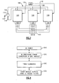
- FIG. 1 illustrates an example aircraft 10 using a power conversion system to convert DC power to AC power.
- the aircraft 10 includes a DC power source 20, which supplies power to a multi-level poly-phase converter 30.
- the multi-level poly-phase converter 30 converts the power into a poly-phase format, such as three-phase, and removes electrical noise from the power.
- the power is then transmitted to on-board electrical components 40 which utilize AC power, thereby powering the electrical components 40.
- Additional noise filtering such as an inductance - capacitance (LC) passive filter 50, can be included after the multi-level poly-phase converter 30 and before the on-board electrical component 40 to further clean the power signal of electrical noise.
- LC inductance - capacitance
- Illustrated in Figure 2 is an example multi-level parallel phase converter 100 which has a DC power source 110 connected to three identical converter modules 120.
- Each of the converter modules 120 has an interphase inductor 122 which outputs power on three phase lines 122A, 122B, 122C (also referred to as power lines).
- the DC power source 110 has a positive side 112, a negative side 114, and a connection to ground 116.
- the illustrated DC power source 110 can be two DC sources connected by a ground connection, thereby providing both a negative voltage DC source 114 and a high voltage DC source 112.
- the multi-level parallel phase converter 100 is referred to as a parallel phase converter because each of the converter modules 120 is connected in a parallel configuration.
- the pulse width modulation creates an AC power output staircase wave.
- the staircase wave is passed through the interphase inductor 122, and the resulting power is output on the phase outputs 122A, 122B, 122C.
- the corresponding phase outputs 122A, 122B, 122C of each converter module 120 are connected together to form a combined AC power output for the overall system at a combination node 132.
- the combined AC power output has a current equal to the sum of the current of each of the individual converter modules 120.
- phase A 122A of each of the interphase inductors 122 would be connected to each other phase A 122A
- phase B 122B would be connected to each other phase B 122B
- phase C 122C would be connected to each other phase C 122C.
- the converter modules 120 are connected to the DC power source 110 parallel to each of the other converter modules 120, thereby allowing for concurrent power conversion.
- the converter system 100 also has a controller 124 which controls each of the converter modules 120.
- the controller 124 outputs a control signal which controls the switching of the multi-level inverters 222, 224, 226 (illustrated in Figure 3 ) contained within each converter module 120.
- the introduction of converter modules beyond two requires the introduction of a phase offset in the control signal, and therefore prevents the converter module 120 outputs from being summed together while a control phase component is present on the output signal.
- N 2
- the phase shift is between the modules is ⁇ , or 180 degrees, and an increase in the number of modules will be accompanied by a corresponding change in the phase shift.
- the size of an attached passive filter in power converter system depends upon the frequency of the noise in AC power of the converter 20. A higher noise frequency generally results in a smaller size requirement for a passive filter.
- the noise frequency of the power output of the multi-level parallel phase converter 100 of Figure 2 is related to number of converter modules 120 and the common switching frequency.
- the addition of the interphase inductor 122 allows additional converter modules 120 to be connected beyond two, and therefore also allows for the system to utilize a higher frequency than could be used with a converter using two modules.
- each converter module 120 is capable of switching at 10kHz
- a converter system having two three-level converter modules 120 is limited to producing an effective switching frequency of 40kHz (4x10kHz).
- the effective switching frequency is at least 2 x N x 10kHz, where N is equal to the number of converter modules.
- the additional converter modules 120 can add redundancy to the power converter 30.
- excess converter modules 120 are installed. When one of the operating converter modules 120 becomes damaged, or otherwise ceases to function, the remaining converter modules 120 continue to operate with a net reduction in output power.
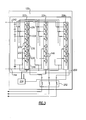
- FIG 3 illustrates a schematic description of a converter module 120 which could be used in the multi-level converter 100 illustrated in Figure 2 .
- the converter module 120 includes a set of poly-phase multi-level inverters 222, 224, 226.
- the illustrated converter module 120 generates three phase power. However, if a different number of phases is desired, additional multi-level inverters 222, 224, 226 can be included equal to the number of additional phases. By way of example, if a six phase system is desired, the converter module 120 will include six multi-level inverters 222, 224, 226.
- Each of the multi-level inverters 222, 224, 226 has a series of semiconductor switch / diode pairs 230.
- the switching of transistors 232 within the transistor / diode pairs 230 is controlled by an on-board converter module controller 234. Alternately, the switching can be controlled by an external controller which is connected to the converter module 120, such as controller 124 of Figure 2 .
- the multi-level converters 222, 224, 226 can have any number semiconductor switch / diode pairs 230, and the specific number of pairs 230 can be determined by a person of ordinary skill in the art to achieve a desired output frequency and voltage.
- Each of the multi-level inverters 222, 224, 226 is also connected to a +DC source 242 and a -DC source 244.
- the switching action of the semiconductor switch / diode pairs 230 creates a multi-level staircase waveform at each of the multi-level inverters 222, 224, 226.
- Each of the levels in the multi-level inverters 222, 224, 226 are summed together and output as a single power output 246, 248, 250.
- the power outputs 246, 248, 250 of each multi-level converter 222, 224, 226 are then passed through an interphase inductor 252 and a leakage inductance of the interphase inductor 252 blocks circulating current between the multiple converter modules 120.
- the interphase inductor 252 represents an embodiment of the interphase inductor 122 of Figure 2 .
- the converter module controller 234 provides an output control signal to each of the transistor / diode pairs 230 using a triangle shaped carrier wave.
- a carrier wave is a cyclical electrical signal which can be modulated to contain data or control information. Due to its cyclical nature, a carrier wave imparts a phase shift on the controlled system. Since each of the controlled converter modules 120 receive independent control signals, the phase shifts imposed on each phase of the output signal by the carrier wave differs between the converter modules 120. When only two converter modules 120 are used the phase shifts can be designed to be 180 degrees apart, and the output signals can be added together without interference by the phase shifts.
- the multi-level parallel phase converter initially accepts DC power 310.
- the DC power is then converted into multiple square-wave AC power outputs in each module step 320.
- the power outputs are combined at 340 on an electrical node into a single combined power output in the power summation step 340.
- Each of the converter modules additionally filters the AC power outputs to remove any electromagnetic noise and to convert the signals into a sinusoidal wave in the filter module step 330.
- bi-directionality allows power to be connected at either the AC connections to the parallel phase converter, or at the DC connections of the parallel phase converter.
Landscapes
- Engineering & Computer Science (AREA)
- Power Engineering (AREA)
- Life Sciences & Earth Sciences (AREA)
- Sustainable Development (AREA)
- Sustainable Energy (AREA)
- Transportation (AREA)
- Mechanical Engineering (AREA)
- Inverter Devices (AREA)
- Rectifiers (AREA)
- Supply And Distribution Of Alternating Current (AREA)
Abstract
Description
- The present disclosure is directed to the field of electric power converters, and more specifically to a multi-level parallel phase converter.
- Conventional power systems, such as those found in electric aircraft, include a power converter to convert DC power into a poly-phase format These systems also include a passive filter. The passive filter is designed to filter out noise introduced into the system as a result of the power switching action. The power converter may "pre-clean" the power. Pre-cleaning removes at least a portion of the electrical noise from the power prior to the passive filter.
- Disclosed is a multi-level power converter which has a power source, a DC/AC converter, and an electrical node. The converter is coupled to the power source and includes multiple converter modules. Each of the converter modules has multiple multi-level power converters, a poly-phase interphase inductor, and a set of poly-phase output connections. Each of the multi-level power converter has power line connected to the poly-phase interphase inductor. The electrical node connects each of the connections in the sets of poly-phase output connections to form a single set of poly-phase connections.
- A plurality of parallel converter modules converts the power into a square wave output which is then passed through a corresponding interphase inductor to from a power output.
- These and other features of the present invention can be best understood from the following specification and drawings, the following of which is a brief description.
-
-
Figure 1 schematically illustrates an aircraft power generation system using a multi-level inverter. -
Figure 2 schematically illustrates a basic level diagram of an example multi-level converter. -
Figure 3 schematically illustrates a sample multi-level DC/AC converter module for an aircraft power system. -
Figure 4 illustrates a flowchart of a process by which a power is pre-cleaned. -
Figure 1 illustrates anexample aircraft 10 using a power conversion system to convert DC power to AC power. Theaircraft 10 includes aDC power source 20, which supplies power to a multi-level poly-phase converter 30. The multi-level poly-phase converter 30 converts the power into a poly-phase format, such as three-phase, and removes electrical noise from the power. The power is then transmitted to on-boardelectrical components 40 which utilize AC power, thereby powering theelectrical components 40. Additional noise filtering, such as an inductance - capacitance (LC)passive filter 50, can be included after the multi-level poly-phase converter 30 and before the on-boardelectrical component 40 to further clean the power signal of electrical noise. - Illustrated in
Figure 2 is an example multi-levelparallel phase converter 100 which has aDC power source 110 connected to threeidentical converter modules 120. Each of theconverter modules 120 has aninterphase inductor 122 which outputs power on three phase lines 122A, 122B, 122C (also referred to as power lines). TheDC power source 110 has apositive side 112, anegative side 114, and a connection toground 116. The illustratedDC power source 110 can be two DC sources connected by a ground connection, thereby providing both a negativevoltage DC source 114 and a highvoltage DC source 112. The multi-levelparallel phase converter 100 is referred to as a parallel phase converter because each of theconverter modules 120 is connected in a parallel configuration. - The pulse width modulation creates an AC power output staircase wave. The staircase wave is passed through the
interphase inductor 122, and the resulting power is output on the phase outputs 122A, 122B, 122C. The corresponding phase outputs 122A, 122B, 122C of eachconverter module 120 are connected together to form a combined AC power output for the overall system at acombination node 132. The combined AC power output has a current equal to the sum of the current of each of theindividual converter modules 120. By way of example, phase A 122A of each of theinterphase inductors 122 would be connected to each other phase A 122A, phase B 122B would be connected to each other phase B 122B, and phase C 122C would be connected to each other phase C 122C. - The
converter modules 120 are connected to theDC power source 110 parallel to each of theother converter modules 120, thereby allowing for concurrent power conversion. Theconverter system 100 also has acontroller 124 which controls each of theconverter modules 120. Thecontroller 124 outputs a control signal which controls the switching of themulti-level inverters Figure 3 ) contained within eachconverter module 120. - The introduction of converter modules beyond two requires the introduction of a phase offset in the control signal, and therefore prevents the
converter module 120 outputs from being summed together while a control phase component is present on the output signal. By way of example, for a system which has N converter modules 120 (where N is any positive integer number), the carrier phase shift between modules is
ith converter module 120 in the system, i = 0, 1, 2 ..., N-1. As can be seen, if there are twoconverter modules 120, N = 2, and the phase shift is between the modules is π, or 180 degrees, and an increase in the number of modules will be accompanied by a corresponding change in the phase shift. - The size of an attached passive filter in power converter system, such as LC
passive filter 50 ofFigure 1 , depends upon the frequency of the noise in AC power of theconverter 20. A higher noise frequency generally results in a smaller size requirement for a passive filter. The noise frequency of the power output of the multi-levelparallel phase converter 100 ofFigure 2 is related to number ofconverter modules 120 and the common switching frequency. The addition of theinterphase inductor 122 allowsadditional converter modules 120 to be connected beyond two, and therefore also allows for the system to utilize a higher frequency than could be used with a converter using two modules. - As an example, if each
converter module 120 is capable of switching at 10kHz, a converter system having two three-level converter modules 120 is limited to producing an effective switching frequency of 40kHz (4x10kHz). The addition ofmultiple converter modules 120 beyond two, allows the effective switching frequency of the output signal to increase in corresponding amounts. The effective switching frequency is at least 2 x N x 10kHz, where N is equal to the number of converter modules. The above described frequency values are exemplary only, and are not intended in a limiting sense. - Alternately, the
additional converter modules 120 can add redundancy to the power converter 30. In a redundant system,excess converter modules 120 are installed. When one of theoperating converter modules 120 becomes damaged, or otherwise ceases to function, theremaining converter modules 120 continue to operate with a net reduction in output power. -
Figure 3 illustrates a schematic description of aconverter module 120 which could be used in themulti-level converter 100 illustrated inFigure 2 . Theconverter module 120 includes a set of poly-phasemulti-level inverters converter module 120 generates three phase power. However, if a different number of phases is desired, additionalmulti-level inverters converter module 120 will include sixmulti-level inverters - Each of the
multi-level inverters diode pairs 230. The switching oftransistors 232 within the transistor /diode pairs 230 is controlled by an on-boardconverter module controller 234. Alternately, the switching can be controlled by an external controller which is connected to theconverter module 120, such ascontroller 124 ofFigure 2 . As indicated by theellipses 270 inFigure 3 , themulti-level converters diode pairs 230, and the specific number ofpairs 230 can be determined by a person of ordinary skill in the art to achieve a desired output frequency and voltage. - Each of the
multi-level inverters DC source 242 and a -DC source 244. The switching action of the semiconductor switch /diode pairs 230 creates a multi-level staircase waveform at each of themulti-level inverters multi-level inverters single power output power outputs multi-level converter interphase inductor 252 and a leakage inductance of theinterphase inductor 252 blocks circulating current between themultiple converter modules 120. Theinterphase inductor 252 represents an embodiment of theinterphase inductor 122 ofFigure 2 . - The
converter module controller 234 provides an output control signal to each of the transistor / diode pairs 230 using a triangle shaped carrier wave. A carrier wave is a cyclical electrical signal which can be modulated to contain data or control information. Due to its cyclical nature, a carrier wave imparts a phase shift on the controlled system. Since each of the controlledconverter modules 120 receive independent control signals, the phase shifts imposed on each phase of the output signal by the carrier wave differs between theconverter modules 120. When only twoconverter modules 120 are used the phase shifts can be designed to be 180 degrees apart, and the output signals can be added together without interference by the phase shifts. - An example process, by which the above described power conversion is made, is illustrated in the flowchart of
Figure 4 . The multi-level parallel phase converter initially acceptsDC power 310. The DC power is then converted into multiple square-wave AC power outputs in eachmodule step 320. The power outputs are combined at 340 on an electrical node into a single combined power output in thepower summation step 340. Each of the converter modules additionally filters the AC power outputs to remove any electromagnetic noise and to convert the signals into a sinusoidal wave in thefilter module step 330. - While the above example is described with regards to a conversion from a DC to an AC signal, a person having ordinary skill in the art could reverse the connections and, with minor modifications, convert an AC power to a DC power using the above described power converter. This functionality is referred to as "bi-directionality." The bi-directionality allows power to be connected at either the AC connections to the parallel phase converter, or at the DC connections of the parallel phase converter.
- Although an embodiment has been disclosed, a worker of ordinary skill in this art would recognize that certain modifications would come within the scope of this invention which is defined by the claims. For that reason, the following claims should be studied to determine the true scope and content of this invention.
Claims (15)
- A multi-level parallel phase power converter comprising:a power source (20;110);a power converter (100) coupled to said power source and having a plurality of converter modules (120,120,120) comprising multi-level power converters, a poly-phase interphase inductor (122,252), and poly-phase output connections (122A,122B,122C;246,248,250), each of said multi-level power converters having a power line connected to said poly-phase interphase inductor; andan electrical node (132) connecting each of said poly-phase output connections, thereby forming a single poly-phase power converter output.
- The multi-level parallel phase power converter of claim 1, wherein said power converter includes two of said converter modules.
- The multi-level parallel phase power converter of claim 1 or 2, wherein each of said converter modules has a number of multi-level power converters equal to a number of output phases of the multi-level power converter.
- The multi-level parallel phase power converter of claim 1, 2 or 3, wherein said single poly-phase power converter is a three phase power configuration.
- The multi-level power converter of claim 4, wherein each of said converter modules has three of said multi-level power converters.
- The multi-level power converter of claim 4 or 5, wherein each of said converter modules is connected in parallel.
- The multi-level parallel phase power converter of any preceding claim, wherein said power converter is capable of converting AC power to DC power.
- The multi-level parallel phase power converter of any of claims 1 to 6, wherein said power converter is capable of converting DC power to AC power.
- The multi-level parallel phase power converter of claim 8, wherein said power converter additionally is capable of converting AC power to DC power, said converter being arranged such that power may be connected at either an AC or DC input.
- The multi-level parallel phase power converter of any preceding claim, wherein said poly-phase interphase inductors are configured to remove a carrier phase component from each of said connected power lines.
- The multi-level parallel phase power converter of claim 10, wherein each of said poly-phase interphase inductors has a leakage inductance, and each of said leakage inductances is configured to remove said carrier phase component from each of said connected lines.
- The multi-level parallel phase power converter of any preceding claim, further comprising redundant converter modules such that said power converter can function while at least one converter module is inoperable.
- The multi-level parallel phase power converter of any preceding claim, wherein each of said power converter modules is operated at a given switching frequency and an output noise frequency on said electrical node is equal to at least two times the number of converter modules multiplied by the given switching frequency.
- A method for converting power comprising the steps of;
inputting DC power (310) into a multi-level parallel phase converter (100) comprising a plurality of converter modules (120,120,120);
each of said converter modules converting said DC power signal into a poly-phase staircase wave power signal;
combining each of said poly-phase staircase wave power in an interphase inductor (122;152), thereby creating an output power; and
filtering said output power signal in a passive filter (50), thereby creating a filtered output power. - The method of claim 14, wherein said step of combining each of said poly-phase staircase wave power in an interphase inductor comprises removing current circulating between the plurality of converter modules.
Applications Claiming Priority (1)
| Application Number | Priority Date | Filing Date | Title |
|---|---|---|---|
| US12/731,280 US8374009B2 (en) | 2010-03-25 | 2010-03-25 | Multi-level parallel phase converter |
Publications (2)
| Publication Number | Publication Date |
|---|---|
| EP2369734A2 true EP2369734A2 (en) | 2011-09-28 |
| EP2369734A3 EP2369734A3 (en) | 2014-12-24 |
Family
ID=44314930
Family Applications (1)
| Application Number | Title | Priority Date | Filing Date |
|---|---|---|---|
| EP11250258.8A Pending EP2369734A3 (en) | 2010-03-25 | 2011-03-07 | Mulit-level parallel phase converter |
Country Status (2)
| Country | Link |
|---|---|
| US (1) | US8374009B2 (en) |
| EP (1) | EP2369734A3 (en) |
Families Citing this family (12)
| Publication number | Priority date | Publication date | Assignee | Title |
|---|---|---|---|---|
| US8411474B2 (en) * | 2010-04-30 | 2013-04-02 | General Electric Company | System and method for protection of a multilevel converter |
| DE102011003810A1 (en) * | 2011-02-08 | 2012-08-09 | Robert Bosch Gmbh | Controllable energy storage and method for operating a controllable energy storage |
| US9941813B2 (en) | 2013-03-14 | 2018-04-10 | Solaredge Technologies Ltd. | High frequency multi-level inverter |
| US9787217B2 (en) * | 2013-08-30 | 2017-10-10 | Huawei Technologies Co., Ltd. | Power conversion circuit and power conversion system |
| US9231492B2 (en) | 2014-01-06 | 2016-01-05 | General Electric Company | System and method of power conversion |
| US9318974B2 (en) | 2014-03-26 | 2016-04-19 | Solaredge Technologies Ltd. | Multi-level inverter with flying capacitor topology |
| EP3314714B1 (en) * | 2015-06-29 | 2019-11-06 | ABB Schweiz AG | A multi-level power converter and a method for controlling a multi-level power converter |
| US9831800B2 (en) | 2016-04-21 | 2017-11-28 | The Florida State University Research Foundation, Inc. | Self-balanced modulation and magnetic rebalancing method for parallel multilevel inverters |
| EP3574579B1 (en) | 2017-01-30 | 2023-11-08 | Carrier Corporation | Paralleled passive front-end rectifiers with and without interleaving |
| CN110463028B (en) | 2017-01-30 | 2023-04-28 | 开利公司 | Method for controlling passive front-end rectifier with and without interleaving |
| US10797612B2 (en) | 2017-08-01 | 2020-10-06 | Ge Aviation Systems Llc | Power distribution network |
| US11710991B2 (en) | 2020-08-25 | 2023-07-25 | General Electric Company | High voltage electric machine equipped with galvanic separators for cascaded voltage stator modularization |
Family Cites Families (29)
| Publication number | Priority date | Publication date | Assignee | Title |
|---|---|---|---|---|
| CH682435A5 (en) * | 1990-11-19 | 1993-09-15 | Inventio Ag | parallel frequency converter network connection method |
| US5198971A (en) * | 1991-08-15 | 1993-03-30 | Recker Bradley J | Separation control for multiphase plural inverter system |
| US5434771A (en) * | 1991-09-12 | 1995-07-18 | Sundstrand Corporation | Adaptive harmonic distortion control for parallel connected inverters |
| US5311419A (en) | 1992-08-17 | 1994-05-10 | Sundstrand Corporation | Polyphase AC/DC converter |
| US5642275A (en) | 1995-09-14 | 1997-06-24 | Lockheed Martin Energy System, Inc. | Multilevel cascade voltage source inverter with seperate DC sources |
| US6084786A (en) | 1999-01-29 | 2000-07-04 | Hamilton Sundstrand Corporation | Converter system with power factor and DC ripple control |
| DE20115474U1 (en) | 2001-09-19 | 2003-02-20 | Biester Klaus | DC converter device |
| US6510063B2 (en) * | 2000-05-30 | 2003-01-21 | Mitsubishi Denki Kabushiki Kaisha | Electric power conversion optimized for efficient harmonic elimination |
| AU2001277128A1 (en) | 2000-07-24 | 2002-02-05 | Hamilton Sundstrand Corporation | Apparatus for ac-to-dc conversion which provides a signed dc signal |
| CA2369060C (en) * | 2001-01-24 | 2005-10-04 | Nissin Electric Co., Ltd. | Dc-dc-converter and bi-directional dc-dc converter and method of controlling the same |
| US6751106B2 (en) | 2002-07-25 | 2004-06-15 | General Electric Company | Cross current control for power converter systems and integrated magnetic choke assembly |
| US7050311B2 (en) | 2003-11-25 | 2006-05-23 | Electric Power Research Institute, Inc. | Multilevel converter based intelligent universal transformer |
| US20070230226A1 (en) | 2003-11-25 | 2007-10-04 | Jih-Sheng Lai | Multilevel intelligent universal auto-transformer |
| US7479746B2 (en) | 2004-03-23 | 2009-01-20 | Hamilton Sundstrand Corporation | Power converter for an electric engine start system |
| JP4626259B2 (en) * | 2004-10-21 | 2011-02-02 | 日産自動車株式会社 | Power converter control method |
| US7518886B1 (en) * | 2005-02-18 | 2009-04-14 | Virginia Tech Intellectual Properties, Inc. | Multiphase soft switched DC/DC converter and active control technique for fuel cell ripple current elimination |
| WO2006090675A1 (en) * | 2005-02-25 | 2006-08-31 | Mitsubishi Denki Kabushiki Kaisha | Power converter |
| US7277304B2 (en) * | 2005-09-23 | 2007-10-02 | Gm Global Technology Operations, Inc. | Multiple inverter system with single controller and related operating method |
| JP5226183B2 (en) | 2006-01-10 | 2013-07-03 | 東芝三菱電機産業システム株式会社 | Multi-level power converter |
| US7423894B2 (en) | 2006-03-03 | 2008-09-09 | Advanced Energy Industries, Inc. | Interleaved soft switching bridge power converter |
| FI119086B (en) * | 2006-11-06 | 2008-07-15 | Abb Oy | Method and arrangement for a wind turbine |
| US7633770B2 (en) | 2006-12-08 | 2009-12-15 | General Electric Company | Collection and transmission system |
| CA2689503C (en) * | 2007-06-04 | 2017-05-09 | Sustainable Energy Technologies | Prediction scheme for step wave power converter and inductive inverter topology |
| US7643319B2 (en) * | 2007-06-22 | 2010-01-05 | General Electric Company | 7-level wye-connected H-bridge converter topology for powering a high-speed electric motor |
| US7852643B2 (en) * | 2007-06-27 | 2010-12-14 | General Electric Company | Cross current control for power converter system |
| JP5255851B2 (en) * | 2008-01-21 | 2013-08-07 | 山洋電気株式会社 | Parallel operation inverter |
| JP4240149B1 (en) * | 2008-02-14 | 2009-03-18 | トヨタ自動車株式会社 | Motor drive device and hybrid drive device |
| US7994750B2 (en) * | 2008-04-29 | 2011-08-09 | General Electric Company | Systems and methods for controlling a converter for powering a load |
| US8885371B2 (en) * | 2010-10-19 | 2014-11-11 | Astec International Limited | Multi-level parallel power converters |
-
2010
- 2010-03-25 US US12/731,280 patent/US8374009B2/en active Active
-
2011
- 2011-03-07 EP EP11250258.8A patent/EP2369734A3/en active Pending
Non-Patent Citations (1)
| Title |
|---|
| None |
Also Published As
| Publication number | Publication date |
|---|---|
| US20110235376A1 (en) | 2011-09-29 |
| EP2369734A3 (en) | 2014-12-24 |
| US8374009B2 (en) | 2013-02-12 |
Similar Documents
| Publication | Publication Date | Title |
|---|---|---|
| US8374009B2 (en) | Multi-level parallel phase converter | |
| US9385632B2 (en) | Multi-level inverter and power supply system | |
| Strzelecki et al. | New type T-source inverter | |
| US9166472B2 (en) | EMI filtering for active rectifier power systems | |
| CN103250340B (en) | For transmitting the device of electric power between DC electric lines of force and AC electric lines of force | |
| RU2379817C1 (en) | High-voltage direct ac converter | |
| Mohamad et al. | A new cascaded multilevel inverter topology with minimum number of conducting switches | |
| JP2006025591A (en) | Vehicular power supply device | |
| US11569746B2 (en) | DC coupled electrical converter | |
| RU2629005C2 (en) | Converter unit with parallelly included multistage semiconductor converters and their control method | |
| CN112421975A (en) | Multilevel power converter with AFE power cell phase control | |
| Nair et al. | Performance of three phase 11-level inverter with reduced number of switches using different PWM techniques | |
| US8629579B2 (en) | Active switching ripple filter | |
| CN103988409B (en) | Power conversion device | |
| Gandomi et al. | High frequency isolated dual active three-phase modular multilevel converter | |
| Sandoval et al. | A new delta inverter system for grid integration of large scale photovoltaic power plants | |
| WO2016177399A1 (en) | Converter arrangement | |
| Asghari-Gorji et al. | Input current ripples cancellation in bidirectional switched-inductor quasi-Z-source inverter using coupled inductors | |
| US20210242797A1 (en) | Power circuits for modular multi-level converters (mmc) and modular multi-level converters | |
| Kim et al. | PWM methods for high frequency voltage link inverter commutation | |
| US11469685B2 (en) | Filter and AFE power cell phase control | |
| EP2662969A1 (en) | Multi-phase multi-level converter | |
| JP4977040B2 (en) | Control device, power conversion device, and control method | |
| JP2006296181A (en) | Ac-dc conversion device | |
| Vijayarajan et al. | A new hybrid multilevel inverter topology for medium and high voltage applications |
Legal Events
| Date | Code | Title | Description |
|---|---|---|---|
| PUAI | Public reference made under article 153(3) epc to a published international application that has entered the european phase |
Free format text: ORIGINAL CODE: 0009012 |
|
| AK | Designated contracting states |
Kind code of ref document: A2 Designated state(s): AL AT BE BG CH CY CZ DE DK EE ES FI FR GB GR HR HU IE IS IT LI LT LU LV MC MK MT NL NO PL PT RO RS SE SI SK SM TR |
|
| AX | Request for extension of the european patent |
Extension state: BA ME |
|
| PUAL | Search report despatched |
Free format text: ORIGINAL CODE: 0009013 |
|
| AK | Designated contracting states |
Kind code of ref document: A3 Designated state(s): AL AT BE BG CH CY CZ DE DK EE ES FI FR GB GR HR HU IE IS IT LI LT LU LV MC MK MT NL NO PL PT RO RS SE SI SK SM TR |
|
| AX | Request for extension of the european patent |
Extension state: BA ME |
|
| RIC1 | Information provided on ipc code assigned before grant |
Ipc: B60L 11/18 20060101ALI20141120BHEP Ipc: H02M 7/483 20070101AFI20141120BHEP Ipc: H02M 7/493 20070101ALI20141120BHEP |
|
| 17P | Request for examination filed |
Effective date: 20150624 |
|
| RBV | Designated contracting states (corrected) |
Designated state(s): AL AT BE BG CH CY CZ DE DK EE ES FI FR GB GR HR HU IE IS IT LI LT LU LV MC MK MT NL NO PL PT RO RS SE SI SK SM TR |
|
| STAA | Information on the status of an ep patent application or granted ep patent |
Free format text: STATUS: EXAMINATION IS IN PROGRESS |
|
| 17Q | First examination report despatched |
Effective date: 20181029 |
|
| STAA | Information on the status of an ep patent application or granted ep patent |
Free format text: STATUS: EXAMINATION IS IN PROGRESS |
|
| RAP3 | Party data changed (applicant data changed or rights of an application transferred) |
Owner name: HAMILTON SUNDSTRAND CORPORATION |