EP3574579B1 - Paralleled passive front-end rectifiers with and without interleaving - Google Patents
Paralleled passive front-end rectifiers with and without interleaving Download PDFInfo
- Publication number
- EP3574579B1 EP3574579B1 EP18704721.2A EP18704721A EP3574579B1 EP 3574579 B1 EP3574579 B1 EP 3574579B1 EP 18704721 A EP18704721 A EP 18704721A EP 3574579 B1 EP3574579 B1 EP 3574579B1
- Authority
- EP
- European Patent Office
- Prior art keywords
- inverter
- controller
- bus
- drive
- phase
- Prior art date
- Legal status (The legal status is an assumption and is not a legal conclusion. Google has not performed a legal analysis and makes no representation as to the accuracy of the status listed.)
- Active
Links
- 238000000034 method Methods 0.000 claims description 31
- 230000016507 interphase Effects 0.000 claims description 26
- 230000008878 coupling Effects 0.000 claims description 24
- 238000010168 coupling process Methods 0.000 claims description 24
- 238000005859 coupling reaction Methods 0.000 claims description 24
- 230000005284 excitation Effects 0.000 claims description 13
- 239000003990 capacitor Substances 0.000 claims description 12
- 230000009467 reduction Effects 0.000 claims description 8
- 238000004804 winding Methods 0.000 claims description 5
- 238000012546 transfer Methods 0.000 claims description 4
- 230000000295 complement effect Effects 0.000 claims description 3
- 230000001939 inductive effect Effects 0.000 description 13
- 239000003507 refrigerant Substances 0.000 description 11
- 230000008901 benefit Effects 0.000 description 8
- 239000011162 core material Substances 0.000 description 6
- 230000006870 function Effects 0.000 description 6
- 230000001360 synchronised effect Effects 0.000 description 6
- 238000013461 design Methods 0.000 description 5
- 239000007788 liquid Substances 0.000 description 5
- 238000010586 diagram Methods 0.000 description 4
- 239000000203 mixture Substances 0.000 description 4
- 238000013459 approach Methods 0.000 description 3
- 230000004907 flux Effects 0.000 description 3
- 230000009286 beneficial effect Effects 0.000 description 2
- 230000008859 change Effects 0.000 description 2
- 238000007906 compression Methods 0.000 description 2
- 238000011161 development Methods 0.000 description 2
- 230000000694 effects Effects 0.000 description 2
- 238000001704 evaporation Methods 0.000 description 2
- 230000008020 evaporation Effects 0.000 description 2
- 239000000463 material Substances 0.000 description 2
- 230000008569 process Effects 0.000 description 2
- 238000012545 processing Methods 0.000 description 2
- 238000005057 refrigeration Methods 0.000 description 2
- 229920006395 saturated elastomer Polymers 0.000 description 2
- 230000001629 suppression Effects 0.000 description 2
- XLYOFNOQVPJJNP-UHFFFAOYSA-N water Substances O XLYOFNOQVPJJNP-UHFFFAOYSA-N 0.000 description 2
- 238000004378 air conditioning Methods 0.000 description 1
- 230000004075 alteration Effects 0.000 description 1
- 230000006835 compression Effects 0.000 description 1
- 238000004590 computer program Methods 0.000 description 1
- 238000001816 cooling Methods 0.000 description 1
- 239000000498 cooling water Substances 0.000 description 1
- 238000012937 correction Methods 0.000 description 1
- 230000003247 decreasing effect Effects 0.000 description 1
- 230000001934 delay Effects 0.000 description 1
- 230000008030 elimination Effects 0.000 description 1
- 238000003379 elimination reaction Methods 0.000 description 1
- 238000010438 heat treatment Methods 0.000 description 1
- 238000009413 insulation Methods 0.000 description 1
- 238000004519 manufacturing process Methods 0.000 description 1
- 238000012986 modification Methods 0.000 description 1
- 230000004048 modification Effects 0.000 description 1
- 230000003071 parasitic effect Effects 0.000 description 1
- 230000001737 promoting effect Effects 0.000 description 1
- 230000004044 response Effects 0.000 description 1
- 239000011555 saturated liquid Substances 0.000 description 1
- 238000009423 ventilation Methods 0.000 description 1
Images


Classifications
-
- H—ELECTRICITY
- H02—GENERATION; CONVERSION OR DISTRIBUTION OF ELECTRIC POWER
- H02P—CONTROL OR REGULATION OF ELECTRIC MOTORS, ELECTRIC GENERATORS OR DYNAMO-ELECTRIC CONVERTERS; CONTROLLING TRANSFORMERS, REACTORS OR CHOKE COILS
- H02P27/00—Arrangements or methods for the control of AC motors characterised by the kind of supply voltage
- H02P27/04—Arrangements or methods for the control of AC motors characterised by the kind of supply voltage using variable-frequency supply voltage, e.g. inverter or converter supply voltage
- H02P27/06—Arrangements or methods for the control of AC motors characterised by the kind of supply voltage using variable-frequency supply voltage, e.g. inverter or converter supply voltage using dc to ac converters or inverters
- H02P27/08—Arrangements or methods for the control of AC motors characterised by the kind of supply voltage using variable-frequency supply voltage, e.g. inverter or converter supply voltage using dc to ac converters or inverters with pulse width modulation
-
- H—ELECTRICITY
- H02—GENERATION; CONVERSION OR DISTRIBUTION OF ELECTRIC POWER
- H02M—APPARATUS FOR CONVERSION BETWEEN AC AND AC, BETWEEN AC AND DC, OR BETWEEN DC AND DC, AND FOR USE WITH MAINS OR SIMILAR POWER SUPPLY SYSTEMS; CONVERSION OF DC OR AC INPUT POWER INTO SURGE OUTPUT POWER; CONTROL OR REGULATION THEREOF
- H02M1/00—Details of apparatus for conversion
- H02M1/0061—Details of apparatus for conversion using discharge tubes
-
- H—ELECTRICITY
- H02—GENERATION; CONVERSION OR DISTRIBUTION OF ELECTRIC POWER
- H02M—APPARATUS FOR CONVERSION BETWEEN AC AND AC, BETWEEN AC AND DC, OR BETWEEN DC AND DC, AND FOR USE WITH MAINS OR SIMILAR POWER SUPPLY SYSTEMS; CONVERSION OF DC OR AC INPUT POWER INTO SURGE OUTPUT POWER; CONTROL OR REGULATION THEREOF
- H02M7/00—Conversion of ac power input into dc power output; Conversion of dc power input into ac power output
- H02M7/42—Conversion of dc power input into ac power output without possibility of reversal
- H02M7/44—Conversion of dc power input into ac power output without possibility of reversal by static converters
- H02M7/48—Conversion of dc power input into ac power output without possibility of reversal by static converters using discharge tubes with control electrode or semiconductor devices with control electrode
- H02M7/493—Conversion of dc power input into ac power output without possibility of reversal by static converters using discharge tubes with control electrode or semiconductor devices with control electrode the static converters being arranged for operation in parallel
-
- H—ELECTRICITY
- H02—GENERATION; CONVERSION OR DISTRIBUTION OF ELECTRIC POWER
- H02M—APPARATUS FOR CONVERSION BETWEEN AC AND AC, BETWEEN AC AND DC, OR BETWEEN DC AND DC, AND FOR USE WITH MAINS OR SIMILAR POWER SUPPLY SYSTEMS; CONVERSION OF DC OR AC INPUT POWER INTO SURGE OUTPUT POWER; CONTROL OR REGULATION THEREOF
- H02M1/00—Details of apparatus for conversion
- H02M1/0003—Details of control, feedback or regulation circuits
-
- H—ELECTRICITY
- H02—GENERATION; CONVERSION OR DISTRIBUTION OF ELECTRIC POWER
- H02M—APPARATUS FOR CONVERSION BETWEEN AC AND AC, BETWEEN AC AND DC, OR BETWEEN DC AND DC, AND FOR USE WITH MAINS OR SIMILAR POWER SUPPLY SYSTEMS; CONVERSION OF DC OR AC INPUT POWER INTO SURGE OUTPUT POWER; CONTROL OR REGULATION THEREOF
- H02M1/00—Details of apparatus for conversion
- H02M1/0043—Converters switched with a phase shift, i.e. interleaved
Definitions
- the subject matter disclosed herein relates generally to the field of motor drives, and more particularly to a motor drive for elevators and HVAC/R chiller systems.
- An elevator system such as traction, hydraulic, and self-propelled elevator systems, based on the application (e.g., high rise buildings) can utilize a power system to propel a car within an elevator shaft.
- Large chiller systems utilize a power system to drive compressors and fan systems.
- the power systems can employ active or passive rectifiers to generate a DC bus and then an inverter scheme to drive the motors. This is done to improve performance of the power system in particular for variable speed or variable capacity systems.
- timing and switching a power from the rectifiers to a direct current (DC) bus includes inherent electromagnetic interference (EMI) problems.
- EMI electromagnetic interference
- EMI noise can be divided into two major groups: differential mode (DM) noise and common-mode (CM) noise.
- DM noises are conducted between phases.
- CM noises are conducted together with all phases through the parasitic capacitors to the ground.
- CM noises are with serious concern for motor drives because CM noises increase the EMI in the motor drive and damage the motor bearing and winding insulation.
- solutions such as adding CM filters to attenuate CM noises are not viable due to the significant weight penalty of each CM filter.
- Conveyance systems such as elevator systems, use machines to impart force to a car carrying passengers.
- Chiller systems use large machines to operate large compressors. The machines employed may need to provide varying power levels depending on the application.
- a motor drive needs to be provided to power the machine.
- a high power drive may not exist, which results in high design costs and lengthy development time to manufacture a suitable drive.
- costs associated with a single, large drive may be excessive due to specialty components, component availability, etc.
- high power drives commonly require expensive high voltage components. Therefore, paralleling drives may provide a more cost effective approach.
- Patent document JP S57 22385 A relates to parallel-connected AC/DC/AC converters, whose outputs are coupled by interphase inductors for current balancing, and discloses the features of the preamble of the independent claim.
- Patent documents US 2006/043922 A1 , EP 0 524 398 A2 and JP S63 28274 A disclose further examples of parallel-connected AC/DC/AC converters, whose outputs are coupled by interphase inductors.
- a three-phase paralleled passive front-end drive comprising: a first rectifier bridge configured for connection to a three phase alternating current power source; a first coupling reactance operably connected to the first rectifier bridge and configured to transfer power from the rectifier to a first direct current (DC) bus; a second rectifier bridge configured for connection to a three phase alternating current power source; a second coupling reactance operably connected to the second rectifier bridge and configured to transfer power from the rectifier bridge to a second direct current (DC) bus, a bus coupler operably coupling the first DC bus to the second DC bus; a first inverter operably connected to the first DC bus; a second inverter operably connected to the second DC bus, the first inverter and second the inverter each configured to provide a plurality of motor excitation signals; a first controller operably connected to the first inverter and the second inverter, the controller configured to generate control signals to cause the first inverter and the second in
- the second coupling reactance may include two series inductors and a parallel capacitor to stabilize the second DC bus.
- the first coupling reactance may include two series inductors and a parallel capacitor to stabilize the first DC bus.
- the second PWM reference signal may be 180 degrees out of phase from the first PWM signal.
- the first or the second coupling reactance may be configured to control a circulation current of the three-phase paralleled passive front-end drive.
- the first inverter and the second inverter may comprise at least six switching devices.
- Each interphase inductor may include a pair of windings and may be configured to control a circulation current of the three-phase paralleled passive front-end drive.
- embodiments herein relate to a rectifier to supply a DC bus that in turn supplies voltage to a converter that drives a motor and configuring the rectifier to minimize or eliminate common mode noise between a direct current (DC) bus and an alternating current (AC) source.
- the embodiments herein relate to timing and switching a power from the rectifier to the DC bus.
- Embodiments herein set forth a drive and motor system and/or method for a rectifier system (e.g., a three-phase passive front-end rectifier) to actively control a DC voltage, an AC side sinusoidal current, and a power factor by fast switching of power electronics devices.
- EMI filters are designed to attenuate EMI noise to satisfy the EMI standards, which are defined for particular applications, but EMI filters add weight and complexity for the rectifier system.
- a more complex topology for an active front-end rectifier can be applied to further reduce the CM voltage.
- paralleled active rectifiers have more control freedoms than the standard two-level rectifier.
- active front-end rectifiers are more complex.
- the three-phase passive front-end rectifier with and without interleaving provides a PWM method to achieve reduced CM-voltage for paralleled rectifiers and inverters that is simpler and more cost effective.
- controller refers to processing circuitry that may include an application specific integrated circuit (ASIC), an electronic circuit, an electronic processor (shared, dedicated, or group) and memory that executes one or more software or firmware programs, a combinational logic circuit, and/or other suitable interfaces and components that provide the described functionality.
- ASIC application specific integrated circuit
- processor shared, dedicated, or group
- memory that executes one or more software or firmware programs, a combinational logic circuit, and/or other suitable interfaces and components that provide the described functionality.
- connection can include an indirect “connection” and a direct “connection”.
- the three-phase passive front-end rectifier is utilized in a power system of a building heating ventilation and air conditioning or refrigeration system (HVAC/R).
- HVAC/R building heating ventilation and air conditioning or refrigeration system
- a building HVAC/R can employ a chiller system driven by a power system including a motor drive with rectifier and inverter as described herein
- the rectifier may be a three-phase passive front-end rectifier.
- a passive rectifier with and without interleaving is disclosed.
- the drive may also include a power electronics inverter (e.g., as a variable speed alternating current (AC) motor drive) to improve the performance of the chiller system.
- AC alternating current
- the three-phase passive front-end rectifier is utilized in an electric motor system 23 of an elevator system.
- the elevator system also includes a hoistway having a plurality of lanes or shafts. In each shaft, one or more elevator car travels to deliver passengers to a desired floor of a building.
- the electric motor system utilizes the power electronics inverter (e.g., as variable speed alternating drive (AC) motor drive) to improve the performance of maneuvering the elevator cars.
- AC variable speed alternating drive
- Other applications and embodiments of the three-phase passive front-end rectifier include powers systems for trains, boats, planes, etc.
- FIG. 1 is a block diagram of components of a power system 10 of an embodiment as may be employed to power one or more building systems or loads 23.
- the power system 10 is described with respect to an HVAC/R system.
- the conventional HVAC/R system incorporates a closed refrigerant loop in a vapor compression cycle.
- the vapor-compression cycle uses a circulating refrigerant as the medium which absorbs and removes heat from the space to be cooled and subsequently rejects that heat elsewhere. All such systems have four basic components: a compressor, a condenser, a thermal expansion valve (also called a throttle valve or metering device), and an evaporator.
- a compressor a condenser
- a thermal expansion valve also called a throttle valve or metering device
- evaporator also called a throttle valve or metering device
- Circulating refrigerant enters the compressor as a saturated vapor and is compressed to a higher pressure, resulting in a higher temperature as well.
- the hot, compressed vapor is then in the thermodynamic state known as a superheated vapor and it is at a temperature and pressure at which it can be condensed with either cooling water or cooling air flowing across the coil or tubes in the condenser. This is where the circulating refrigerant rejects heat from the system and the rejected heat is carried away by either the water or the air (whichever may be the case).
- the condensed liquid refrigerant, in the thermodynamic state known as a saturated liquid is next routed through an expansion valve where it undergoes an abrupt reduction in pressure. That pressure reduction results in the flash evaporation of a part of the liquid refrigerant. The evaporation lowers the temperature of the liquid and vapor refrigerant mixture to where it is colder than the temperature of the enclosed space to be refrigerated.
- the cold mixture is then routed through the coil or tubes in the evaporator.
- a fan circulates the warm air in the enclosed space across the coil or tubes carrying the cold refrigerant liquid and vapor mixture. That warm air evaporates the liquid part of the cold refrigerant mixture.
- the circulating air is cooled and thus lowers the temperature of the enclosed space to the desired temperature.
- the evaporator is where the circulating refrigerant absorbs and removes heat which is subsequently rejected in the condenser and transferred elsewhere by the water or air used in the condenser.
- the refrigerant vapor from the evaporator is again a saturated vapor and is routed back into the compressor.
- the compressor is large and driven by a very large motor requiring dedicated motor drives with high voltage and current capabilities.
- power system 10 includes a source of AC power 12, such as an electrical main line (e.g., 440 volt, 3-phase).
- the AC power 12 is provided to a motor drive system 20.
- drive system 20 includes a plurality of drives arranged in a parallel electrical configuration. Each drive system 20 may include a rectifier 32, 32' or converter to convert the AC power 12 to a DC voltage.
- Each drive system 20 may include an inverter 40, 40' to convert the DC voltage to multiphase, AC drive signals to drive a machine 22 (shown in Figure 1 ).
- Drive signals from the drive system 20 are supplied to the machine 22 to operate the load 23.
- load 23 For example, turn a compressor or impart motion to elevator car.
- machine 22 includes a multiphase, permanent magnet synchronous motor 21.
- the drive system 20 includes paralleled drives 30 and 30' in an embodiment.
- the two drives 30, 30' include a passive rectifier 32, 32' and an inverter 40, and 40' connected in parallel to provide drive signals to motor 21.
- each inverter 40 and 40' is controlled by a separate drive controller, 60 and 60', respectively.
- Drive controllers 60 and 60' provide control signals 62, 62', 64 to the inverters 40 and 40', respectively, to control generation of the drive signals to motor 21.
- Drive controllers 60, 60' may be implemented using a general-purpose microprocessor executing a computer program stored on a storage medium to perform the operations described herein. Alternatively, drive controllers 60, 60' may be implemented in hardware (e.g., ASIC, FPGA) or in a combination of hardware/software.
- Each drive 30 and 30' is 2 level, 3 phase drives, such as that shown in FIG. 3 .
- Drives 30 and 30' are placed in parallel by electrically connecting the positive DC bus of each drive 30 and 30' as will be described in further detail herein.
- the 3 phase drive signals from drives 30 and 30' are connected to an inductive interface 50, which combines each respective phase from the drives 30 and 30' through inductive elements 52, 54, 56 (e.g., inductors).
- Inductive interface 50 allows for combining phases from two separate drives 30 and 30'.
- Inductive interface 50 also acts as a voltage suppression filter.
- the inductive interface 50 is one or more interphase inductors. Interphase inductors are commonly configured as two windings on a common core with opposite polarity ends tied together as the common output.
- a conventional interphase inductor would operate pass signals that are different from each of the inputs, but would block or cancel signals that are common.
- the interphase inductor operates to sum the motor excitation signals (namely the currents) from the paralleled inverters 40 and 40' yet suppress common mode circulating currents.
- a properly designed interphase reactor/inductor 52, 54, 56 will sum up current from each inverter 40 40' and without imposing any voltage drop across it for the fundamental voltage waveform while it prevents current that try to run from one inverter to the other.
- two drives 30 and 30' are shown in FIG. 2 , it is understood that embodiments may include more than two drives connected in parallel.
- FIG. 3 is a more detailed diagram of the 2 level, 3-phase paralleled drive 20 of an embodiment.
- Each of the drives 30, 30' includes a passive rectifier bridge 32, 32' having 3 phase input, R, S and T.
- Each phase leg, R, S and T is directed to a conventional three phase rectifier bridge 32, 32' to convert AC power from the utility 12 to DC power.
- the output of the rectifier bridge 32, 32' is directed through a set of coupling reactors that are employed to stabilize/smooth (lower total harmonic distortion) and provide equal sharing of the utility current to the paralleled rectifier bridge 32, 32'.
- the coupling reactors are configured as conventional LC circuit with the inductances 42, 42' and 44, 44' in series and the capacitors 46, 46' in parallel on the output of the rectifier bridge 32, 32' respectively.
- the capacitor 46, 46' is placed across a first DC bus 34 with a positive terminal 36 and a negative terminal 38 and a second DC bus 34'with a positive terminal 36' and a negative terminal 38', respectively.
- DC bus coupling 48 ties together the positive terminal 36 for the first DC bus 34 with a positive terminal 36' of the second DC 34'
- DC bus coupling 49 ties together the negative terminal 38 of the first DC bus 34 with the negative terminal 38' of a second DC bus 34'.
- the LC circuit in cooperation operates to stabilize the current and voltage and loads of the DC bus 34, 34' and maintain equal sharing of (input) current on each DC bus 34, 34'.
- the coupling reactors particularly the series inductors 42, 42', 44, 44', and being placed on the DC side of the rectifiers 32 and 32', they may also be placed on the AC side of the rectifier 32, and 32' between rectifier bridge 32 and 32'and utility source power 12 in the form of conventional 3 phase reactors.
- Drive 30 also includes a first inverter 40 having 3 phase legs, W, V, U. Each phase leg, W, V, and U, includes switches controlled by control signals from a drive controller 60 (See FIG. 4 ) in a conventional manner to convert DC power across the DC bus 34, 36 to AC drive signals to power motor 21, which is part of machine 22 (not shown).
- drive 30' includes a second inverter 40' once again having 3 phase legs, W', V', U'.
- Each phase leg, W, V, and U, and W', V', and U' includes switches controlled by control signals from at least one drive controller to convert DC power across the DC bus 34-36 and 34'-36' to AC drive signals to power motor 21, which is part of machine 22.
- the inverters 40, 40' are conventional for motor drives. In an embodiment, the inverters 40, 40' employ at least six switching devices in three separate parallel legs.
- the paralleled drive 20 also includes inductive interface 50 with interphase inductors 52, 54, 56 corresponding to the respective phases of the motor 21 (not shown).
- the interphase inductors 52, 54, 56 combine the inputs to the motor 21 from each of the paralleled inverters 40, 40'.
- interphase inductor 52 combines inverter phase output U and U' to form a U command to the motor 21.
- Interphase inductor 54 combines inverter phase output V and V' to form a V command to the motor 21.
- interphase inductor 56 combines inverter phase output W and W' to form a W command to the motor 21.
- the drive 30, includes a passive rectifier bridge 32, having 3 phase input, R, S and T.
- Each phase leg, R, S and T is directed to a conventional three phase rectifier bridge 32 to convert AC power to DC power.
- a second rectifier bridge is not employed, instead, the rectifier bridge 32 is employed for both drives 30 and 30'.
- the output of the rectifier bridge 32 is directed through a set of reactors that are employed to stabilize the current from the paralleled rectifier bridge 32.
- the reactors are configured as conventional LC circuit with the inductances 42 and 44 in series and the capacitor 46 in parallel on the output of the rectifier bridge 32 respectively.
- the capacitor 46 is placed across a first DC bus 34 with a positive terminal 36 and a negative terminal 38.
- a second capacitor 46' is placed across a second DC bus 34'with a positive terminal 36' and a negative terminal 38' respectively.
- DC bus coupling 48 ties together the positive terminal 36 for the first DC bus 34 with a positive terminal 36' of the second DC bus 34'
- DC bus coupling 49 ties together the negative terminal 38 of the first DC bus 34' with the negative terminal 38' of a second DC bus 34'.
- the inductors 42, 44 operate with increased impedance to oppose those changes.
- capacitor 46, 46" operates in a conventional manner to oppose and voltage changes on the DC bus 34, 34'.
- the DC bus coupling 48 and 49 ties the DC busses 34, 34' together. Thereby, the LC circuit in cooperation operates to stabilize the current and voltage and loads of the DC bus 34, 34'.
- drive 30 also includes a first inverter 40 connected and operating as described above, and likewise, drive 30' includes a second inverter 40' also connected and operating as described above.
- Paralleled drive 20 also includes inductive interface 50 with interphase inductors 52, 54, 56 corresponding to the respective phases of the motor 21 connected and operating as described above.
- FIG 5 where a control methodology 200 for the paralleled drive 20 is depicted.
- the drive signals at the output of the drives be synchronized. Due to variations in the components, switching devices, drive controllers 60, 60' and inverters 40, 40', using identical control signals may not result in synchronized outputs U, V, and W with U', V', and W' from the drives 30, 30'.
- drive controllers 60 and 60' execute a methodology 200 to align the control signals 62, 62' ( FIG 2 ) provided to the respective drives 30, 30', and in particular the inverters 40, 40'.
- FIG. 1 A methodology 200 to align the control signals 62, 62' ( FIG 2 ) provided to the respective drives 30, 30', and in particular the inverters 40, 40'.
- a first pulse width modulation (PWM) signal 80 for generating the control signals 62 from drive controller 60 for one phase (e.g., any of U, V, or W) of the inverter 40 of drive 30, for example, and a second PWM signal 82 for generating a second control signal 62' from drive controller 60' for one phase (e.g., any of U', V', or W' but corresponding to the PWM signals 80 and 82 above respectively) of the inverter 40' of drive 30', for example.
- the control signals 62, 62' are ideally identical and that variations between the control signals 62, 62' are small and designed to address variations in components, timing, and the like.
- a reference point 84 of the first PWM signal 80 is defined. As shown in FIG. 5 , the reference point 84 is a minimum value of the PWM signal 80, however, any reference point may be used.
- first drive controller 60 communicates to the second drive controller 60' when the reference point 84 has occurred in PWM signal 80. Second drive controller 60' then determines when the reference point 86 occurs in its PWM signal 82. If there is a difference between when the reference point 84 occurs in the first PWM signal 80 and when the reference point 86 occurs in the second PWM signal 82, then one or both of the drive controllers 60 and 60' may adjust the period of the PWM signals 80, 82 such that the reference points 84, 86 occur at the same time as depicted at process step 215. It should be noted that process steps 210 and 215 are depicted as dashed because they are optional for other embodiments disclosed herein.
- the first drive controller 60 or second drive controller 60' may use known techniques to adjust the period of the PWM signals 80, 82, such as a phase locked loop technique to reduce error between when the reference points 84 occurs in control signal 80 and when the reference point 86 occurs in control signal 82. This improves synchronization of the control signals 62, 62' between inverters 40 and 40' for drives 30 and 30', which allows smaller inductive elements to be used in inductive interface 50.
- the control signal synchronization as described may be used with any number of drives, and is not limited to two drives.
- the control signal synchronization of FIG. 5 may be used with the drives other than those shown in FIG. 3 or 4 .
- the control signals 62, 62' generated by the controller 60, 60' may be pulse width modulation (PWM) signals, commonly used in n-level drives and many inverter control applications.
- PWM pulse width modulation
- the duty cycle of the control signals 62, 62' is varied as required based on the output current requirements of the load as depicted at process step 220.
- the desired duty cycle is generated by a motor control demand, commonly a current and speed value. In many applications the speed value dominates the commanded duty cycle while the current value may have a smaller contribution.
- the pulse width of the control signals 62, 62' is increased, thereby the switching devices of the inverter 40, 40' remain on for a commensurate duration and directing more current to the motor 21.
- the duty cycle of the control signals 62, 62' is decreased by the controller 60, 60'. Therefore, employing the described techniques, the synchronization between the controllers 60, 60' and the commands to the inverters may be accomplished as depicted at process step 230.
- using the duty cycle control with the control signals 62, 62' facilitates accurate control of the motor excitation signals U, V, and W.
- an alternative control methodology is described in concert with a different topology for the drive 120.
- a single controller usually a DSP or microcontroller
- the same controller 60 is generating the control signals 60, 64 for the two inverters 40 and 40' no special synchronization in required (as it is inherent to being generated by the single controller). That is, because the control signals 60, 64 to the inverters 40, 40' are generated in the same controller 60, there are no delays between controllers, in wiring, and the like, and synchronization techniques are not needed.
- the controller 60 executes a process similar as described above for the first drive 30 and inverter 40.
- controller 60 provides a second set of control signals 64 also from drive controller 60 that are essentially the same as the first. In fact, in an embodiment, they are the same.
- control signals 60, 64 may be pulse width modulation signals, commonly used in n-level drives as described in the earlier embodiments.
- the first drive controller 60 may use conventional pulse width modulation techniques to control the duty cycle (on time) of the control signals 60, 64 to the inverters 40 and 40'and thereby the current provided by the inverters 40 and 40'.
- This technique is very simple because no synchronization is needed or required when the commands for the two inverters 40 and 40' are made from the same controller.
- it would not address any corrections needed to ensure that inverter 40 and 40' equally share the current load.
- any imbalance would be uncompensated.
- any imbalance would cause the inductive interface 50, and in particular, interphase inductors 52, 54, 56 to carry the additional burden of the imbalance between current outputs of the inverters 40 and 40'. Excessive imbalance could cause the interface inductors 52, 54, 56 to lose their ability to block circulating currents due to core saturation, thus requiring larger inductors to remain effective.
- the perturbation is on the order of ⁇ 1-2% of the duty cycle for the control signals 60, 64.
- the variation or perturbation is introduced in a complementary in nature, that is, if for one inverter, e.g. inverter 40, the perturbation is an increase in nominal duty cycle for the control signal 60, for the other inverter e.g., 40' the perturbation is a reduction in duty cycle of the control signal 64.
- the variation or perturbation for inverter 40 is decrease the nominal duty cycle of the control signal 60, then for the other inverter e.g., 40' the perturbation is an increase duty cycle of the control signal 64.
- any imbalance in the current output of the inverter 40 versus 40' may be reduced or eliminated while maintaining the overall desired duty cycle required and thereby the commanded excitation signals (U, V, and W as well as U', V', W') to the motor 21 to achieve the desired response.
- this approach reduces the impact of current sharing imbalance on the two inverters 40 and 40' and thereby the impact on the interphase inductors 52, 54, and 56.
- This approach also minimizes the requirements on the interphase inductors 52, 54, and 56 as the net core flux in each under balanced condition is zero and hence core material can be reduced.
- FIG. 7 depicts one period of a first PWM signal 80 from drive controller 60 for one phase (e.g., any of U, V, or W) of the inverter 40 of drive 30 just as described for earlier embodiments.
- second PWM signal 82 from drive controller 60' for one phase e.g., any of U', V', or W' but corresponding to the PWM signal 80 above
- the second PWM signal 82 is defined to be 180 degrees out of phase with the first control signal 80.
- the PWM signals 80, 82 may be pulse width modulation signals, commonly used in n-level drives.
- a first reference point 84 of the first PWM signal 80 is defined, similar as to the embodiment described above.
- the first reference point 84 is a minimum value of the PWM signal 80, however, any reference point may be used.
- a second reference point 88 is selected.
- a maximum point in the control signal 80 is selected and depicted in the figure, almost any other point could be selected.
- 90 degrees following the first reference point 84 (a minimum) is selected for the second reference point 88.
- first drive controller 60 communicates to the second drive controller 60' when the first reference point 84 and the second reference point 88 have occurred in the PWM signal 80.
- Second drive controller 60' determines when the first reference point 84 and second reference point 88 occurs in its PWM signal 82. If there is a difference, accounting for the 180 degree shift between when the two reference points 84, 86 occur in the first PWM signal 80 and when the two reference points 84, 86 occurs in the second PWM signal 82, then one or both of the drive controllers 60 and 60' may adjust the period of the PWM signals 80 or 82 (and thereby the control signals 62, 62') respectively such that the reference points 84, 86 of the respective PWM signals 80, 82 occur at the same time.
- the first drive controller 60 or second drive controller 60' may use known techniques to adjust the period of the drive signal 80, 82, such as a phase locked loop technique to reduce error between when the reference point occurs in PWM signal 80 and when the reference point occurs in PWM signal 82.
- This improves synchronization of the control signals 62, 62' between inverters 40 and 40' for drives 30 and 30', albeit with the phase difference mentioned above.
- it allows for less burden and the potential for smaller rectifiers, to be used in the rectifier bridge 32, 32'.
- it facilitates a reduced burden on the DC bus 32, 32' and reactances 42, 44, and 46 as none or less of the switching devices of the inverters 40, 40' are demanding current at the same time.
- control signals 62, 62' are interleaved such that one drives demands are offset from the others.
- An additional advantageous feature of the interleaving control methodology described is that due to the 180 degree shift of the second control signal 86.
- the apparent frequency of noise, switching, ripple applied to the interphase inductances 52, 54, and 56 and the motor 21 is doubled. As a result, the size the interphase inductors 52, 54, and 56 may be reduced.
- the frequency of the PWM may be reduced to half.
- the PWM frequency doubling has an additional benefit as it reduces acoustic impact on users.
- the human ear is less sensitive to higher frequency and the amplitude is reduced by half. Reducing the PWM frequency reduces the switching losses in the switching devices of the inverter 40, 40'depending on the configuration of the drive, the switching losses can be 30 percent of the losses in the switching devices.
- the control signals 62, 62' synchronization as described may be used with any number of drives, and is not limited to two drives.
- the control signal 62, 62' synchronization of FIG. 7 may be used with the drives other than those shown in FIG. 3 or 4 .
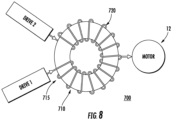
- FIG. 8 shows the interphase inductor physical structure 700 that includes, but is not limited to, a toroidal core 710.
- Two equivalent windings 715, 720 with inversed directions are employed with their common point tied to a phase of the motor 12, ideally summing the outputs of the two drive inputs.
- the interphase inductor flux is generated by the current that goes through both branches, creating canceling flux in the core to benefit minimal voltage drop for fundamental voltage, while the inductance from one drive to the other drive remains to limit the circulating current. Therefore, by controlling equal currents from the drives and by the benefit of interphase inductor the size and also the voltage drop that it could incur in case the currents are not balanced is minimized. It should be appreciated that the actual design of the coupling inductor will most likely still result in some leakage inductance from each drive to the motor. This residual leakage inductance will also function to provide motor surge voltage suppression.
- Embodiments include the use of paralleled drives in order to meet high load demands without the need to design or source a single, high power drive.
- Using parallel drives with passive rectifiers and the control methodologies described herein allows the drive system to meet load demands through multiple, lower power drives. This eliminates the cost and/or development time associated with a single, higher power drive.
- the technical effects and benefits of embodiments of a rectifier system include achieving reduced CM-voltage that enables control capability of the DC-link voltage for passive front-end rectifier system. Eliminating common-mode voltage for the inverter output results in significant reductions of CM EMI noise, and eliminating a need for CM EMI filters, along with a reduction of an input current ripple, DC side (e.g., DC capacitor) current ripple, and a conducted EMI. Further, the technical effects and benefits of embodiments can include balancing in each switching cycle output voltages for two paralleled rectifiers and a circulating current.
Description
- The subject matter disclosed herein relates generally to the field of motor drives, and more particularly to a motor drive for elevators and HVAC/R chiller systems.
- An elevator system, such as traction, hydraulic, and self-propelled elevator systems, based on the application (e.g., high rise buildings) can utilize a power system to propel a car within an elevator shaft. Large chiller systems utilize a power system to drive compressors and fan systems. At present, the power systems can employ active or passive rectifiers to generate a DC bus and then an inverter scheme to drive the motors. This is done to improve performance of the power system in particular for variable speed or variable capacity systems. However, timing and switching a power from the rectifiers to a direct current (DC) bus includes inherent electromagnetic interference (EMI) problems. Likewise timing and switching of power in an inverter generates significant EMI.
- In general, EMI noise can be divided into two major groups: differential mode (DM) noise and common-mode (CM) noise. DM noises are conducted between phases. CM noises are conducted together with all phases through the parasitic capacitors to the ground. CM noises are with serious concern for motor drives because CM noises increase the EMI in the motor drive and damage the motor bearing and winding insulation. Unfortunately, in certain applications, solutions such as adding CM filters to attenuate CM noises are not viable due to the significant weight penalty of each CM filter.
- Conveyance systems, such as elevator systems, use machines to impart force to a car carrying passengers. Chiller systems use large machines to operate large compressors. The machines employed may need to provide varying power levels depending on the application. When either an elevator system or a chiller system requires a large duty or load, a motor drive needs to be provided to power the machine. Often, a high power drive may not exist, which results in high design costs and lengthy development time to manufacture a suitable drive. Even if a single, large drive exists in the marketplace, costs associated with a single, large drive may be excessive due to specialty components, component availability, etc. Also, high power drives commonly require expensive high voltage components. Therefore, paralleling drives may provide a more cost effective approach.
- Patent document
JP S57 22385 A US 2006/043922 A1 ,EP 0 524 398 A2 andJP S63 28274 A - According to a first aspect of the present invention there is provided a three-phase paralleled passive front-end drive, comprising: a first rectifier bridge configured for connection to a three phase alternating current power source; a first coupling reactance operably connected to the first rectifier bridge and configured to transfer power from the rectifier to a first direct current (DC) bus; a second rectifier bridge configured for connection to a three phase alternating current power source; a second coupling reactance operably connected to the second rectifier bridge and configured to transfer power from the rectifier bridge to a second direct current (DC) bus, a bus coupler operably coupling the first DC bus to the second DC bus; a first inverter operably connected to the first DC bus; a second inverter operably connected to the second DC bus, the first inverter and second the inverter each configured to provide a plurality of motor excitation signals; a first controller operably connected to the first inverter and the second inverter, the controller configured to generate control signals to cause the first inverter and the second inverter to generate a plurality of motor excitation signals respectively; a plurality of interphase inductors operable to combine the plurality of motor excitation signals from the first inverter with the plurality of motor excitation signals from the second inverter; and a second controller wherein the first controller and the second controller implement a method to cause the first inverter and the second inverter to provide substantially equal motor excitation currents respectively; wherein the first controller generates a first pulse width modulation (PWM) reference signal and the second controller generates a second PWM reference signal; the first controller and the second controller each generate a duty cycle for the control signals based on the first PWM reference signal and second PWM reference signals respectively; the first controller generates a first set of control signals to the first inverter and the second controller generates a second set of control signals to the second inverter based on the first PWM reference signal and second PWM reference signals respectively; the first controller communicates timing of a reference point on the first PWM reference signal to the second controller, the second controller adjusting a period of the second PWM reference signal based on the timing; and characterized in that: at least one of the first controller and the second controller perturb the duty cycle of each of the first set of control signals and the second set of control signals based on at least one of the first PWM reference signal and second PWM reference signal, wherein the duty cycles are perturbed by introducing a perturbation that is complementary in nature such that if for one of the inverters the perturbation is an increase in duty cycle for the control signal, then for the other inverter the perturbation is a reduction in duty cycle of the control signal.
- The second coupling reactance may include two series inductors and a parallel capacitor to stabilize the second DC bus.
- The first coupling reactance may include two series inductors and a parallel capacitor to stabilize the first DC bus.
- The second PWM reference signal may be 180 degrees out of phase from the first PWM signal.
- The first or the second coupling reactance may be configured to control a circulation current of the three-phase paralleled passive front-end drive.
- The first inverter and the second inverter may comprise at least six switching devices.
- Each interphase inductor may include a pair of windings and may be configured to control a circulation current of the three-phase paralleled passive front-end drive.
- Additional features and advantages are realized through the techniques of the present disclosure. Other embodiments and aspects of the disclosure are described in detail herein. For a better understanding of the disclosure with the advantages and the features, refer to the description and to the drawings.
- The subject matter which is regarded as the invention is particularly pointed out and distinctly claimed in the claims at the conclusion of the specification. The foregoing and other features, and advantages of the invention are apparent from the following detailed description taken in conjunction with the accompanying drawings in which:
-
FIG. 1 depicts a power system for a building system in accordance with an embodiment; -
FIG. 2 shows a block diagram of three-phase paralleled drive in accordance with an embodiment; -
FIG. 3 illustrates a simplified schematic of passive rectifier paralleled drive in accordance with an embodiment; -
FIG. 4 a simplified schematic of passive rectifier paralleled drive in accordance with an embodiment; -
FIG. 5 depicts a method of controlling passive rectifier paralleled drive in accordance with an embodiment; -
FIG. 6 illustrates a control signal for a passive rectifier paralleled drive in accordance with an embodiment; -
FIG. 7 illustrates a control signal for a passive rectifier paralleled drive in accordance with an embodiment; and -
FIG. 8 depicts a coupling inductor structure in accordance with an embodiment. - In general, embodiments herein relate to a rectifier to supply a DC bus that in turn supplies voltage to a converter that drives a motor and configuring the rectifier to minimize or eliminate common mode noise between a direct current (DC) bus and an alternating current (AC) source. In this way, the embodiments herein relate to timing and switching a power from the rectifier to the DC bus. Embodiments herein set forth a drive and motor system and/or method for a rectifier system (e.g., a three-phase passive front-end rectifier) to actively control a DC voltage, an AC side sinusoidal current, and a power factor by fast switching of power electronics devices.
- Generally, the switching of power electronics devices in passive front-end rectifier also brings electromagnetic interference (EMI) problems. EMI filters are designed to attenuate EMI noise to satisfy the EMI standards, which are defined for particular applications, but EMI filters add weight and complexity for the rectifier system. Further, a more complex topology for an active front-end rectifier can be applied to further reduce the CM voltage. For example, paralleled active rectifiers have more control freedoms than the standard two-level rectifier. However active front-end rectifiers are more complex. Thus, the three-phase passive front-end rectifier with and without interleaving provides a PWM method to achieve reduced CM-voltage for paralleled rectifiers and inverters that is simpler and more cost effective.
- For the purposes of promoting an understanding of the principles of the present disclosure, reference will now be made to the embodiments illustrated in the drawings, and specific language will be used to describe the same. It will nevertheless be understood that no limitation of the scope of this disclosure is thereby intended. The following description is merely illustrative in nature and is not intended to limit the present disclosure, its application or uses. It should be understood that throughout the drawings, corresponding reference numerals indicate like or corresponding parts and features. As used herein, the term controller refers to processing circuitry that may include an application specific integrated circuit (ASIC), an electronic circuit, an electronic processor (shared, dedicated, or group) and memory that executes one or more software or firmware programs, a combinational logic circuit, and/or other suitable interfaces and components that provide the described functionality.
- Additionally, the term "exemplary" is used herein to mean "serving as an example, instance or illustration." Any embodiment or design described herein as "exemplary" is not necessarily to be construed as preferred or advantageous over other embodiments or designs. The terms "at least one" and "one or more" are understood to include any integer number greater than or equal to one, i.e. one, two, three, four, etc. The terms "a plurality" are understood to include any integer number greater than or equal to two, i.e. two, three, four, five, etc. The term "connection" can include an indirect "connection" and a direct "connection".
- As shown and described herein, various features of the disclosure will be presented. Various embodiments may have the same or similar features and thus the same or similar features may be labeled with the same reference numeral, but preceded by a different first number indicating the figure to which the feature is shown. Thus, for example, element "a" that is shown in Figure X may be labeled "Xa" and a similar feature in Figure Z may be labeled "Za." Although similar reference numbers may be used in a generic sense, various embodiments will be described and various features may include changes, alterations, modifications, etc. as will be appreciated by those of skill in the art, whether explicitly described or otherwise would be appreciated by those of skill in the art.
- In one embodiment, the three-phase passive front-end rectifier is utilized in a power system of a building heating ventilation and air conditioning or refrigeration system (HVAC/R). For example, a building HVAC/R can employ a chiller system driven by a power system including a motor drive with rectifier and inverter as described herein In some instances the rectifier may be a three-phase passive front-end rectifier. In an embodiment a passive rectifier with and without interleaving is disclosed. The drive may also include a power electronics inverter (e.g., as a variable speed alternating current (AC) motor drive) to improve the performance of the chiller system.
- In another embodiment, the three-phase passive front-end rectifier is utilized in an
electric motor system 23 of an elevator system. The elevator system also includes a hoistway having a plurality of lanes or shafts. In each shaft, one or more elevator car travels to deliver passengers to a desired floor of a building. The electric motor system utilizes the power electronics inverter (e.g., as variable speed alternating drive (AC) motor drive) to improve the performance of maneuvering the elevator cars. Other applications and embodiments of the three-phase passive front-end rectifier include powers systems for trains, boats, planes, etc. -
FIG. 1 is a block diagram of components of apower system 10 of an embodiment as may be employed to power one or more building systems or loads 23. In an embodiment thepower system 10 is described with respect to an HVAC/R system. The conventional HVAC/R system incorporates a closed refrigerant loop in a vapor compression cycle. The vapor-compression cycle uses a circulating refrigerant as the medium which absorbs and removes heat from the space to be cooled and subsequently rejects that heat elsewhere. All such systems have four basic components: a compressor, a condenser, a thermal expansion valve (also called a throttle valve or metering device), and an evaporator. Circulating refrigerant enters the compressor as a saturated vapor and is compressed to a higher pressure, resulting in a higher temperature as well. The hot, compressed vapor is then in the thermodynamic state known as a superheated vapor and it is at a temperature and pressure at which it can be condensed with either cooling water or cooling air flowing across the coil or tubes in the condenser. This is where the circulating refrigerant rejects heat from the system and the rejected heat is carried away by either the water or the air (whichever may be the case). The condensed liquid refrigerant, in the thermodynamic state known as a saturated liquid, is next routed through an expansion valve where it undergoes an abrupt reduction in pressure. That pressure reduction results in the flash evaporation of a part of the liquid refrigerant. The evaporation lowers the temperature of the liquid and vapor refrigerant mixture to where it is colder than the temperature of the enclosed space to be refrigerated. - The cold mixture is then routed through the coil or tubes in the evaporator. A fan circulates the warm air in the enclosed space across the coil or tubes carrying the cold refrigerant liquid and vapor mixture. That warm air evaporates the liquid part of the cold refrigerant mixture. At the same time, the circulating air is cooled and thus lowers the temperature of the enclosed space to the desired temperature. The evaporator is where the circulating refrigerant absorbs and removes heat which is subsequently rejected in the condenser and transferred elsewhere by the water or air used in the condenser. To complete the refrigeration cycle, the refrigerant vapor from the evaporator is again a saturated vapor and is routed back into the compressor. In large scale HVAC systems or chillers, the compressor is large and driven by a very large motor requiring dedicated motor drives with high voltage and current capabilities.
- Although some embodiments are described with respect to an HVAC system, it is understood that embodiments may be applied to other systems with large motor controls. Further, the embodiments are directed and described with respect to elevator systems, but again may be applied to other conveyance systems (e.g., trains, automobiles, marine). Turning now to
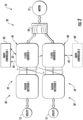
Figure 2 as well,power system 10 includes a source ofAC power 12, such as an electrical main line (e.g., 440 volt, 3-phase). TheAC power 12 is provided to amotor drive system 20. As described in further detail herein,drive system 20 includes a plurality of drives arranged in a parallel electrical configuration. Eachdrive system 20 may include arectifier 32, 32' or converter to convert theAC power 12 to a DC voltage. Eachdrive system 20 may include aninverter 40, 40' to convert the DC voltage to multiphase, AC drive signals to drive a machine 22 (shown inFigure 1 ). Drive signals from thedrive system 20 are supplied to themachine 22 to operate theload 23. For example, turn a compressor or impart motion to elevator car. In an exemplary embodiment,machine 22 includes a multiphase, permanentmagnet synchronous motor 21. - As shown in
Figure 2 , thedrive system 20 includes paralleled drives 30 and 30' in an embodiment. The two drives 30, 30' include apassive rectifier 32, 32' and aninverter 40, and 40' connected in parallel to provide drive signals tomotor 21. In an embodiment eachinverter 40 and 40' is controlled by a separate drive controller, 60 and 60', respectively. Drivecontrollers 60 and 60' providecontrol signals inverters 40 and 40', respectively, to control generation of the drive signals tomotor 21. Drivecontrollers 60, 60' may be implemented using a general-purpose microprocessor executing a computer program stored on a storage medium to perform the operations described herein. Alternatively, drivecontrollers 60, 60' may be implemented in hardware (e.g., ASIC, FPGA) or in a combination of hardware/software. - Each
drive 30 and 30' is 2 level, 3 phase drives, such as that shown inFIG. 3 .Drives 30 and 30' are placed in parallel by electrically connecting the positive DC bus of each drive 30 and 30' as will be described in further detail herein. The 3 phase drive signals fromdrives 30 and 30' are connected to aninductive interface 50, which combines each respective phase from thedrives 30 and 30' throughinductive elements Inductive interface 50 allows for combining phases from twoseparate drives 30 and 30'.Inductive interface 50 also acts as a voltage suppression filter. In an embodiment, theinductive interface 50 is one or more interphase inductors. Interphase inductors are commonly configured as two windings on a common core with opposite polarity ends tied together as the common output. A conventional interphase inductor would operate pass signals that are different from each of the inputs, but would block or cancel signals that are common. To that end, the interphase inductor operates to sum the motor excitation signals (namely the currents) from the paralleledinverters 40 and 40' yet suppress common mode circulating currents. In other words a properly designed interphase reactor/inductor inverter 40 40' and without imposing any voltage drop across it for the fundamental voltage waveform while it prevents current that try to run from one inverter to the other. Although twodrives 30 and 30' are shown inFIG. 2 , it is understood that embodiments may include more than two drives connected in parallel. -
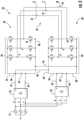
FIG. 3 is a more detailed diagram of the 2 level, 3-phase paralleleddrive 20 of an embodiment. Each of thedrives 30, 30' includes apassive rectifier bridge 32, 32' having 3 phase input, R, S and T. Each phase leg, R, S and T, is directed to a conventional threephase rectifier bridge 32, 32' to convert AC power from theutility 12 to DC power. The output of therectifier bridge 32, 32' is directed through a set of coupling reactors that are employed to stabilize/smooth (lower total harmonic distortion) and provide equal sharing of the utility current to the paralleledrectifier bridge 32, 32'. In an embodiment, the coupling reactors are configured as conventional LC circuit with theinductances capacitors rectifier bridge 32, 32' respectively. Thecapacitor first DC bus 34 with apositive terminal 36 and anegative terminal 38 and a second DC bus 34'with apositive terminal 36' and a negative terminal 38', respectively.DC bus coupling 48 ties together thepositive terminal 36 for thefirst DC bus 34 with apositive terminal 36' of the second DC 34', whileDC bus coupling 49 ties together thenegative terminal 38 of thefirst DC bus 34 with the negative terminal 38' of a second DC bus 34'. In operation, current and voltages will change on theDC bus 34 or 34' as a function of the switching and loading in theinverter 40, 40'. In addition, paralleling therectifiers 32, 32' andinverters 40, 40' will introduce the potential for circulating currents. Theinductors capacitors DC bus 34, 34'. TheDC bus coupling DC bus 34, 34' and maintain equal sharing of (input) current on eachDC bus 34, 34'. It will be appreciated that while the embodiments herein are described with reference to the coupling reactors particularly theseries inductors rectifiers 32 and 32', they may also be placed on the AC side of therectifier 32, and 32' betweenrectifier bridge 32 and 32'andutility source power 12 in the form of conventional 3 phase reactors. -
Drive 30 also includes afirst inverter 40 having 3 phase legs, W, V, U. Each phase leg, W, V, and U, includes switches controlled by control signals from a drive controller 60 (SeeFIG. 4 ) in a conventional manner to convert DC power across theDC bus power motor 21, which is part of machine 22 (not shown). Likewise, drive 30' includes a second inverter 40' once again having 3 phase legs, W', V', U'. Each phase leg, W, V, and U, and W', V', and U' includes switches controlled by control signals from at least one drive controller to convert DC power across the DC bus 34-36 and 34'-36' to AC drive signals topower motor 21, which is part ofmachine 22. Theinverters 40, 40' are conventional for motor drives. In an embodiment, theinverters 40, 40' employ at least six switching devices in three separate parallel legs. - Continuing with
FIG 3 , the paralleleddrive 20 also includesinductive interface 50 withinterphase inductors interphase inductors motor 21 from each of the paralleledinverters 40, 40'. In particular,interphase inductor 52 combines inverter phase output U and U' to form a U command to themotor 21.Interphase inductor 54 combines inverter phase output V and V' to form a V command to themotor 21. Lastly,interphase inductor 56 combines inverter phase output W and W' to form a W command to themotor 21. - Turning now to
FIG. 4 where a detailed diagram of a 2 level, 3-phase paralleled drive 120 of another embodiment is depicted. In this embodiment, the components and configuration are similar to the previous embodiments with the reference numerals increased by 100. Furthermore, where the reference numerals are unchanged, the function and description is the same as identified above with reference to those particular figures. In this embodiment thedrive 30, includes apassive rectifier bridge 32, having 3 phase input, R, S and T. Each phase leg, R, S and T, is directed to a conventional threephase rectifier bridge 32 to convert AC power to DC power. In this embodiment, a second rectifier bridge is not employed, instead, therectifier bridge 32 is employed for bothdrives 30 and 30'. The output of therectifier bridge 32 is directed through a set of reactors that are employed to stabilize the current from the paralleledrectifier bridge 32. In an embodiment, the reactors are configured as conventional LC circuit with theinductances capacitor 46 in parallel on the output of therectifier bridge 32 respectively. Thecapacitor 46 is placed across afirst DC bus 34 with apositive terminal 36 and anegative terminal 38. Optionally asecond capacitor 46' is placed across a second DC bus 34'with apositive terminal 36' and a negative terminal 38' respectively.DC bus coupling 48 ties together thepositive terminal 36 for thefirst DC bus 34 with apositive terminal 36' of the second DC bus 34', whileDC bus coupling 49 ties together thenegative terminal 38 of the first DC bus 34' with the negative terminal 38' of a second DC bus 34'. In operation, current and voltages will change on theDC bus 34 or 34' as a function of the switching and loading in theinverter 40, 40'. Theinductors capacitor DC bus 34, 34'. TheDC bus coupling DC bus 34, 34'. - Continuing with
FIG 4 , as with the earlier embodiments drive 30 also includes afirst inverter 40 connected and operating as described above, and likewise, drive 30' includes a second inverter 40' also connected and operating as described above. Paralleled drive 20 also includesinductive interface 50 withinterphase inductors motor 21 connected and operating as described above. - Turning now to
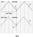
FIG 5 , where acontrol methodology 200 for the paralleleddrive 20 is depicted. To facilitate combining the drive output signals of separate drives (e.g., 30/30') at theinductive interface 50, it is beneficial that the drive signals at the output of the drives be synchronized. Due to variations in the components, switching devices, drivecontrollers 60, 60' andinverters 40, 40', using identical control signals may not result in synchronized outputs U, V, and W with U', V', and W' from thedrives 30, 30'. In order to aid in synchronizing the outputs from two or more drives e.g., 30, 30', drivecontrollers 60 and 60' execute amethodology 200 to align the control signals 62, 62' (FIG 2 ) provided to therespective drives 30, 30', and in particular theinverters 40, 40'.FIG. 6 depicts a first pulse width modulation (PWM) signal 80 for generating the control signals 62 fromdrive controller 60 for one phase (e.g., any of U, V, or W) of theinverter 40 ofdrive 30, for example, and asecond PWM signal 82 for generating a second control signal 62' from drive controller 60' for one phase (e.g., any of U', V', or W' but corresponding to the PWM signals 80 and 82 above respectively) of the inverter 40' of drive 30', for example. It should be noted, that the control signals 62, 62' are ideally identical and that variations between the control signals 62, 62' are small and designed to address variations in components, timing, and the like. In operation, at process step 205 areference point 84 of thefirst PWM signal 80 is defined. As shown inFIG. 5 , thereference point 84 is a minimum value of thePWM signal 80, however, any reference point may be used. - During operation, as depicted at
process step 210,first drive controller 60 communicates to the second drive controller 60' when thereference point 84 has occurred inPWM signal 80. Second drive controller 60' then determines when thereference point 86 occurs in itsPWM signal 82. If there is a difference between when thereference point 84 occurs in thefirst PWM signal 80 and when thereference point 86 occurs in thesecond PWM signal 82, then one or both of thedrive controllers 60 and 60' may adjust the period of the PWM signals 80, 82 such that thereference points process step 215. It should be noted that process steps 210 and 215 are depicted as dashed because they are optional for other embodiments disclosed herein. Thefirst drive controller 60 or second drive controller 60' may use known techniques to adjust the period of the PWM signals 80, 82, such as a phase locked loop technique to reduce error between when thereference points 84 occurs incontrol signal 80 and when thereference point 86 occurs incontrol signal 82. This improves synchronization of the control signals 62, 62' betweeninverters 40 and 40' fordrives 30 and 30', which allows smaller inductive elements to be used ininductive interface 50. The control signal synchronization as described may be used with any number of drives, and is not limited to two drives. The control signal synchronization ofFIG. 5 may be used with the drives other than those shown inFIG. 3 or4 . - The control signals 62, 62' generated by the
controller 60, 60' may be pulse width modulation (PWM) signals, commonly used in n-level drives and many inverter control applications. In conventional PWM, the duty cycle of the control signals 62, 62' is varied as required based on the output current requirements of the load as depicted atprocess step 220. For example, the desired duty cycle is generated by a motor control demand, commonly a current and speed value. In many applications the speed value dominates the commanded duty cycle while the current value may have a smaller contribution. For example, if more speed or torque is required in by themotor 21, the pulse width of the control signals 62, 62' is increased, thereby the switching devices of theinverter 40, 40' remain on for a commensurate duration and directing more current to themotor 21. Likewise, if a reduction in the speed or output current from thedrive 30, 30' is needed, the duty cycle of the control signals 62, 62' is decreased by thecontroller 60, 60'. Therefore, employing the described techniques, the synchronization between thecontrollers 60, 60' and the commands to the inverters may be accomplished as depicted atprocess step 230. In addition, using the duty cycle control with the control signals 62, 62' facilitates accurate control of the motor excitation signals U, V, and W. - Continuing with
Figure 5 , in another embodiment, an alternative control methodology is described in concert with a different topology for thedrive 120. In this embodiment, a single controller (usually a DSP or microcontroller) 60 is employed. In this embodiment because thesame controller 60 is generating the control signals 60, 64 for the twoinverters 40 and 40' no special synchronization in required (as it is inherent to being generated by the single controller). That is, because the control signals 60, 64 to theinverters 40, 40' are generated in thesame controller 60, there are no delays between controllers, in wiring, and the like, and synchronization techniques are not needed. In an embodiment, thecontroller 60 executes a process similar as described above for thefirst drive 30 andinverter 40. However, in this instance,controller 60 provides a second set of control signals 64 also fromdrive controller 60 that are essentially the same as the first. In fact, in an embodiment, they are the same. Once again the control signals 60, 64 may be pulse width modulation signals, commonly used in n-level drives as described in the earlier embodiments. - During operation, the
first drive controller 60 may use conventional pulse width modulation techniques to control the duty cycle (on time) of the control signals 60, 64 to theinverters 40 and 40'and thereby the current provided by theinverters 40 and 40'. This technique is very simple because no synchronization is needed or required when the commands for the twoinverters 40 and 40' are made from the same controller. However, in this configuration, while simple from controller configuration, it would not address any corrections needed to ensure thatinverter 40 and 40' equally share the current load. Unfortunately, then, any imbalance would be uncompensated. In addition, any imbalance would cause theinductive interface 50, and in particular,interphase inductors inverters 40 and 40'. Excessive imbalance could cause theinterface inductors - To address this consideration and any potential imbalance in the current outputs of the
inverter 40 when compared to 40', in an embodiment another methodology for generating the inverter control signals 60, 64 from thecontroller 60 is disclosed. In this embodiment, similar to the embodiment above, once again asingle controller 60 is employed. Once again as described above, conventional PWM duty cycle control technique may be employed to formulate the control signals 60, 64 to theinverters 40 and 40'. In this instance, however, to address the imbalance conditions identified above, beyond the duty cycle required to address the desired operation, a small variation or perturbation to the commanded duty cycle for each of the control signals 60, 64 to theinverters 40 and 40' is introduced as depicted atoptional process step 225 ofFIG. 5 . The amount of perturbation required is small, only sufficient to overcome sharing imbalances between the twodrives 40 and 40'. In an embodiment, the perturbation is on the order of <1-2% of the duty cycle for the control signals 60, 64. The variation or perturbation is introduced in a complementary in nature, that is, if for one inverter,e.g. inverter 40, the perturbation is an increase in nominal duty cycle for thecontrol signal 60, for the other inverter e.g., 40' the perturbation is a reduction in duty cycle of thecontrol signal 64. Likewise, if the variation or perturbation forinverter 40 is decrease the nominal duty cycle of thecontrol signal 60, then for the other inverter e.g., 40' the perturbation is an increase duty cycle of thecontrol signal 64. In this manner, any imbalance in the current output of theinverter 40 versus 40' may be reduced or eliminated while maintaining the overall desired duty cycle required and thereby the commanded excitation signals (U, V, and W as well as U', V', W') to themotor 21 to achieve the desired response. Advantageously this approach reduces the impact of current sharing imbalance on the twoinverters 40 and 40' and thereby the impact on theinterphase inductors interphase inductors - Continuing with
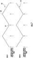
FIG. 5 and now with references toFIG. 7 , in another embodiment, another control methodology is described. To facilitate combining the drive output signals of separate drives (e.g., 30, 30') at theinductive interface 50, once again, it is beneficial that the drive signals at the output of the drives be synchronized to minimize the required inductive interface. It will be appreciated as mentioned above that there are many reasons that despite employing identical commands, the control signals 60, and 62 to theinverters 40 and 40' may not be synchronized. In an embodiment in order to aid in synchronizing the outputs from two or more drives e.g., 30, 30', drivecontrollers 60 and 60' execute another process similar to that described above to align, the control signals 60, and 62 provided to therespective drives 30, 30', and in particular theinverters 40, 40'.FIG. 7 depicts one period of afirst PWM signal 80 fromdrive controller 60 for one phase (e.g., any of U, V, or W) of theinverter 40 ofdrive 30 just as described for earlier embodiments. Once againsecond PWM signal 82 from drive controller 60' for one phase (e.g., any of U', V', or W' but corresponding to thePWM signal 80 above) of the inverter 40' of drive 30' is depicted. However, in this embodiment, it should be noted that thesecond PWM signal 82 is defined to be 180 degrees out of phase with thefirst control signal 80. The PWM signals 80, 82 may be pulse width modulation signals, commonly used in n-level drives. - In operation, once again a
first reference point 84 of thefirst PWM signal 80 is defined, similar as to the embodiment described above. As shown inFIG. 7 , thefirst reference point 84 is a minimum value of thePWM signal 80, however, any reference point may be used. In addition, asecond reference point 88 is selected. Once again, while a maximum point in thecontrol signal 80 is selected and depicted in the figure, almost any other point could be selected. For simplicity, in processing a maximum, 90 degrees following the first reference point 84 (a minimum) is selected for thesecond reference point 88. Similar to that described above, during operation,first drive controller 60 communicates to the second drive controller 60' when thefirst reference point 84 and thesecond reference point 88 have occurred in thePWM signal 80. Second drive controller 60' then determines when thefirst reference point 84 andsecond reference point 88 occurs in itsPWM signal 82. If there is a difference, accounting for the 180 degree shift between when the tworeference points first PWM signal 80 and when the tworeference points second PWM signal 82, then one or both of thedrive controllers 60 and 60' may adjust the period of the PWM signals 80 or 82 (and thereby the control signals 62, 62') respectively such that thereference points - The
first drive controller 60 or second drive controller 60' may use known techniques to adjust the period of thedrive signal PWM signal 80 and when the reference point occurs inPWM signal 82. This improves synchronization of the control signals 62, 62' betweeninverters 40 and 40' fordrives 30 and 30', albeit with the phase difference mentioned above. When synchronized in accordance with this embodiment it allows for less burden and the potential for smaller rectifiers, to be used in therectifier bridge 32, 32'. In addition, it facilitates a reduced burden on theDC bus 32, 32' andreactances inverters 40, 40' are demanding current at the same time. That is, that that the control signals 62, 62' are interleaved such that one drives demands are offset from the others. In addition, it would readily facilitate the elimination of the second rectifier bridge 32' and reactances 42', 44' as described in an earlier embodiment. An additional advantageous feature of the interleaving control methodology described is that due to the 180 degree shift of thesecond control signal 86. The apparent frequency of noise, switching, ripple applied to theinterphase inductances motor 21 is doubled. As a result, the size theinterphase inductors interphase inductances inverter 40, 40'depending on the configuration of the drive, the switching losses can be 30 percent of the losses in the switching devices. The control signals 62, 62' synchronization as described may be used with any number of drives, and is not limited to two drives. Thecontrol signal 62, 62' synchronization ofFIG. 7 may be used with the drives other than those shown inFIG. 3 or4 . -
FIG. 8 shows the interphase inductorphysical structure 700 that includes, but is not limited to, atoroidal core 710. Twoequivalent windings motor 12, ideally summing the outputs of the two drive inputs. The interphase inductor flux is generated by the current that goes through both branches, creating canceling flux in the core to benefit minimal voltage drop for fundamental voltage, while the inductance from one drive to the other drive remains to limit the circulating current. Therefore, by controlling equal currents from the drives and by the benefit of interphase inductor the size and also the voltage drop that it could incur in case the currents are not balanced is minimized. It should be appreciated that the actual design of the coupling inductor will most likely still result in some leakage inductance from each drive to the motor. This residual leakage inductance will also function to provide motor surge voltage suppression. - Embodiments include the use of paralleled drives in order to meet high load demands without the need to design or source a single, high power drive. Using parallel drives with passive rectifiers and the control methodologies described herein, allows the drive system to meet load demands through multiple, lower power drives. This eliminates the cost and/or development time associated with a single, higher power drive.
- In view of the above, the technical effects and benefits of embodiments of a rectifier system include achieving reduced CM-voltage that enables control capability of the DC-link voltage for passive front-end rectifier system. Eliminating common-mode voltage for the inverter output results in significant reductions of CM EMI noise, and eliminating a need for CM EMI filters, along with a reduction of an input current ripple, DC side (e.g., DC capacitor) current ripple, and a conducted EMI. Further, the technical effects and benefits of embodiments can include balancing in each switching cycle output voltages for two paralleled rectifiers and a circulating current.
- The terminology used herein is for the purpose of describing particular embodiments only and is not intended to be limiting of the invention. As used herein, the singular forms "a", "an" and "the" are intended to include the plural forms as well, unless the context clearly indicates otherwise. It will be further understood that the terms "comprises" and/or "comprising," when used in this specification, specify the presence of stated features, integers, steps, operations, elements, and/or components, but do not preclude the presence or addition of one more other features, integers, steps, operations, element components, and/or groups thereof.
- The corresponding structures, materials, acts, and equivalents of all means or step plus function elements in the claims below are intended to include any structure, material, or act for performing the function in combination with other claimed elements as specifically claimed. The description of the present invention has been presented for purposes of illustration and description, but is not intended to be exhaustive or limited to the invention in the form disclosed. The embodiment was chosen and described in order to best explain the principles of the invention and the practical application, and to enable others of ordinary skill in the art to understand the invention for various embodiments as are suited to the particular use contemplated.
Claims (6)
- A three-phase paralleled passive front-end drive, comprising:a first rectifier bridge (32) configured for connection to a three phase alternating current power source (12);a first coupling reactance (42, 44, 46) operably connected to the first rectifier bridge and configured to transfer power from the first rectifier bridge to a first direct current (DC) bus (34);a second rectifier bridge (32') configured for connection to a three phase alternating current power source (12);a second coupling reactance (42', 44', 46') operably connected to the second rectifier bridge and configured to transfer power from the second rectifier bridge to a second direct current (DC) bus (34'),a bus coupler (48, 49) operably coupling the first DC bus to the second DC bus;a first inverter (40) operably connected to the first DC bus;a second inverter (40') operably connected to the second DC bus, the first inverter and second the inverter each configured to provide a plurality of motor excitation signals;a first controller (60) operably connected to the first inverter and the second inverter, the controller configured to generate control signals to cause the first inverter and the second inverter to generate a plurality of motor excitation signals respectively;a plurality of interphase inductors (52, 54, 56) operable to combine the plurality of motor excitation signals from the first inverter with the plurality of motor excitation signals from the second inverter; anda second controller (60') wherein the first controller and the second controller implement a method to cause the first inverter and the second inverter to provide substantially equal motor excitation currents respectively;wherein the first controller generates a first pulse width modulation (PWM) reference signal (80) and the second controller generates a second PWM reference signal (82);the first controller and the second controller each generate a duty cycle for the control signals based on the first PWM reference signal and second PWM reference signals respectively,the first controller generates a first set of control signals (62) to the first inverter and the second controller generates a second set of control signals (62') to the second inverter based on the first PWM reference signal and second PWM reference signals respectively;the first controller (60) communicates timing of a reference point (84) on the first PWM reference signal (80) to the second controller (60'), the second controller adjusting a period of the second PWM reference signal (82) based on the timing; and characterized in that: at least one of the first controller (60) and the second controller (60') perturb the duty cycle of each of the first set of control signals (62) and the second set of control signals (62') based on at least one of the first PWM reference signal (80) and second PWM reference signal (82), wherein the duty cycles are perturbed by introducing a perturbation that is complementary in nature such that if for one of the inverters the perturbation is an increase in duty cycle for the control signal, then for the other inverter the perturbation is a reduction in duty cycle of the control signal.
- The three-phase paralleled passive front-end drive of claim 1, wherein at least one of the first coupling reactance and the second coupling reactance includes two series inductors (42, 44, 42', 44') and a parallel capacitor (46, 46') to stabilize the first DC bus (34) and second DC bus (34') respectively.
- The three-phase paralleled passive front-end drive of claim 1, wherein the second PWM reference signal (82) is 180 degrees out of phase from the first PWM reference signal (80).
- The three-phase paralleled passive front-end drive of claim 1, wherein the first coupling reactance (42, 44, 46) or the second coupling reactance (42', 44', 46') is configured to control a circulation current of the three-phase paralleled passive front-end drive.
- The three-phase paralleled passive front-end drive of claim 1, wherein the first inverter (40) and the second inverter (40') comprise at least six switching devices.
- The three-phase paralleled passive front-end drive of claim 1, wherein each interphase inductor (52, 54, 56) includes a pair of windings and is configured to control a circulation current of the three-phase paralleled passive front-end drive.
Applications Claiming Priority (2)
| Application Number | Priority Date | Filing Date | Title |
|---|---|---|---|
| US201762452150P | 2017-01-30 | 2017-01-30 | |
| PCT/US2018/015473 WO2018140744A1 (en) | 2017-01-30 | 2018-01-26 | Paralleled passive front-end rectifiers with and without interleaving |
Publications (2)
| Publication Number | Publication Date |
|---|---|
| EP3574579A1 EP3574579A1 (en) | 2019-12-04 |
| EP3574579B1 true EP3574579B1 (en) | 2023-11-08 |
Family
ID=61193100
Family Applications (1)
| Application Number | Title | Priority Date | Filing Date |
|---|---|---|---|
| EP18704721.2A Active EP3574579B1 (en) | 2017-01-30 | 2018-01-26 | Paralleled passive front-end rectifiers with and without interleaving |
Country Status (5)
| Country | Link |
|---|---|
| US (1) | US10944335B2 (en) |
| EP (1) | EP3574579B1 (en) |
| CN (1) | CN110226286B (en) |
| ES (1) | ES2962908T3 (en) |
| WO (1) | WO2018140744A1 (en) |
Families Citing this family (6)
| Publication number | Priority date | Publication date | Assignee | Title |
|---|---|---|---|---|
| JP6422619B2 (en) * | 2016-05-25 | 2018-11-14 | 三菱電機株式会社 | Electronic control unit |
| CN110463028B (en) * | 2017-01-30 | 2023-04-28 | 开利公司 | Method for controlling passive front-end rectifier with and without interleaving |
| CN110226286B (en) | 2017-01-30 | 2024-02-02 | 开利公司 | Parallel passive front-end rectifiers with and without interleaving |
| CN111181376B (en) * | 2019-12-23 | 2023-10-27 | 深圳市核达中远通电源技术股份有限公司 | Three-phase staggered parallel buck PFC circuit and control method thereof |
| EP3879687A1 (en) * | 2020-03-13 | 2021-09-15 | Hamilton Sundstrand Corporation | Estimation of the capacitance in the dc link of a motor drive |
| DE102022103770A1 (en) | 2022-02-17 | 2023-08-17 | Dr. Ing. H.C. F. Porsche Aktiengesellschaft | Traction drive inverter arrangement |
Family Cites Families (71)
| Publication number | Priority date | Publication date | Assignee | Title |
|---|---|---|---|---|
| US3792286A (en) | 1971-10-12 | 1974-02-12 | Reliance Electric Co | Combining inverters for harmonic reduction |
| US3902073A (en) | 1974-02-07 | 1975-08-26 | Gen Electric | Starter generator electrical system utilizing phase controlled rectifiers to drive a dynamoelectric machine as a brushless dc motor in the starter mode and to provide frequency conversion for a constant frequency output in the generating mode |
| US3958173A (en) | 1975-02-11 | 1976-05-18 | Gould Inc. | Power converter employing non-saturating interphase transformer |
| JPS5722385A (en) * | 1980-07-15 | 1982-02-05 | Hitachi Ltd | Pulse width modulation type converter |
| US4349772A (en) | 1980-12-23 | 1982-09-14 | General Electric Company | Method and apparatus for controlling an alternating current motor load using plural controlled-current inverter circuits |
| JPS6328274A (en) * | 1986-07-19 | 1988-02-05 | Yaskawa Electric Mfg Co Ltd | Large capacity transistor inverter |
| JPS63287371A (en) | 1987-05-15 | 1988-11-24 | Mitsubishi Electric Corp | Interphase reactor multiplex system pwm inverter |
| JP2685586B2 (en) | 1989-06-30 | 1997-12-03 | 株式会社日立製作所 | Multiple inverter device |
| US5130561A (en) | 1990-08-29 | 1992-07-14 | Alcatel Network Systems, Inc. | Switching mode power supplies with controlled synchronization |
| CA2074176A1 (en) | 1990-11-19 | 1992-05-20 | Ronald Rohner | Method and device for switching inverters in parallel |
| JP3185257B2 (en) | 1991-07-23 | 2001-07-09 | 株式会社明電舎 | Power conversion unit parallel operation device |
| US5191518A (en) | 1991-08-15 | 1993-03-02 | Recker Bradley J | Plural inverter control arrangement |
| US5434771A (en) | 1991-09-12 | 1995-07-18 | Sundstrand Corporation | Adaptive harmonic distortion control for parallel connected inverters |
| US5245525A (en) | 1991-10-24 | 1993-09-14 | Sundstrand Corporation | DC current control through an interphase transformer using differential current sensing |
| US5193054A (en) | 1991-10-24 | 1993-03-09 | Sundstrand Corporation | DC content control in a dual VSCF converter system |
| US5499178A (en) | 1991-12-16 | 1996-03-12 | Regents Of The University Of Minnesota | System for reducing harmonics by harmonic current injection |
| WO1993023913A1 (en) | 1992-05-11 | 1993-11-25 | Electric Power Research Institute | Optimized high power voltage sourced inverter system |
| JPH05344773A (en) | 1992-06-09 | 1993-12-24 | Mitsubishi Electric Corp | Parallel operation controller for pwm inverter |
| JP3226609B2 (en) | 1992-06-24 | 2001-11-05 | 三菱電機株式会社 | Parallel operation control device for power converter |
| JP2888068B2 (en) | 1992-11-30 | 1999-05-10 | 株式会社日立製作所 | Control method of parallel multiple inverter and device thereof |
| WO1995024069A1 (en) | 1994-03-02 | 1995-09-08 | Kabushiki Kaisha Yaskawa Denki | Multi-coupled power converter and its controlling method |
| US6075717A (en) * | 1996-05-01 | 2000-06-13 | General Electric Company | PWM rectifier control with switching losses equally distributed among multiple switching devices |
| JPH09331682A (en) | 1996-06-12 | 1997-12-22 | Meidensha Corp | Power converter |
| US5903066A (en) | 1996-10-29 | 1999-05-11 | Texas A & M University System | Active interphase reactor for 12-pulse rectifier |
| US5910892A (en) | 1997-10-23 | 1999-06-08 | General Electric Company | High power motor drive converter system and modulation control |
| US5905642A (en) | 1997-11-11 | 1999-05-18 | Robicon Corporation | Apparatus and method to reduce common mode voltage from current source drives |
| US6694438B1 (en) | 1999-07-02 | 2004-02-17 | Advanced Energy Industries, Inc. | System for controlling the delivery of power to DC computer components |
| CN1228908C (en) | 2001-12-31 | 2005-11-23 | 艾默生网络能源有限公司 | Switch synchronization method of parallel converter system. |
| FR2842962B1 (en) * | 2002-07-26 | 2004-12-03 | Technofan | INTERFACE FOR SUPPLYING A LOAD FROM AN ELECTRICAL SUPPLY NETWORK |
| EP1427094A3 (en) | 2002-12-06 | 2006-01-25 | Loher GmbH | Method for operating several pulse controlled inverters connected in parallel |
| EP1460022A1 (en) | 2003-03-20 | 2004-09-22 | Inventio Ag | Drive unit for elevator |
| US7102343B1 (en) | 2003-03-31 | 2006-09-05 | Invensys Systems, Inc. | Methods and systems having multiple cooperating transformers |
| EP1575156B1 (en) | 2004-02-16 | 2015-06-17 | Vacon Oyj | Synchronization of parallel-connected inverter units or frequency converters |
| US7109681B2 (en) | 2004-08-25 | 2006-09-19 | Hamilton Sundstrand Corporation | Parallel inverter motor drive with improved waveform and reduced filter requirements |
| FI118876B (en) | 2006-08-25 | 2008-04-15 | Vacon Oyj | Power balance in parallel connected drives |
| FI118875B (en) | 2006-09-26 | 2008-04-15 | Vacon Oyj | Parallel connection of inverters |
| US7667351B2 (en) | 2007-04-27 | 2010-02-23 | Liebert Corporation | Method for pulse width modulation synchronization in a parallel UPS system |
| JP4576407B2 (en) | 2007-07-30 | 2010-11-10 | 株式会社日立製作所 | Set parallel configuration power converter and elevator system using the same |
| JP4538475B2 (en) | 2007-08-17 | 2010-09-08 | 株式会社日立製作所 | Set parallel power converter |
| DE102008037064A1 (en) | 2008-08-08 | 2010-02-11 | Bayerische Motoren Werke Aktiengesellschaft | Circuit arrangement for an electric drive |
| KR101230743B1 (en) | 2008-08-22 | 2013-02-07 | 도시바 미쓰비시덴키 산교시스템 가부시키가이샤 | Power converting apparatus |
| US7825726B2 (en) | 2008-10-30 | 2010-11-02 | Freescale Semiconductor, Inc. | Digital pulse width modulation for half bridge amplifiers |
| US7738267B1 (en) | 2009-01-07 | 2010-06-15 | Rockwell Automation Technologies, Inc. | Systems and methods for common-mode voltage reduction in AC drives |
| DE102009001271A1 (en) | 2009-03-02 | 2010-09-09 | BSH Bosch und Siemens Hausgeräte GmbH | Method for determining the loading and / or the imbalance of a laundry drum of a washing machine and corresponding circuit arrangement |
| GB2470591A (en) | 2009-05-29 | 2010-12-01 | Powervation Ltd | Pulse width modulation synchronisation of switched mode power converters |
| EP2270970B1 (en) | 2009-07-02 | 2012-04-04 | Converteam Technology Ltd | Control methods for the synchronisation of parallel-connected power converters operating in accordance with a pulse width modulation (PWM) strategy |
| US8374009B2 (en) | 2010-03-25 | 2013-02-12 | Hamilton Sundstrand Corporation | Multi-level parallel phase converter |
| FI122367B (en) | 2010-04-15 | 2011-12-30 | Abb Oy | Method and arrangement in connection with an electric drive system |
| US8188694B2 (en) | 2010-07-16 | 2012-05-29 | Rockwell Automation Technologies, Inc. | Parallel power inverter motor drive system |
| CN201860122U (en) * | 2010-09-25 | 2011-06-08 | 天津理工大学 | Current type multilevel converter applied to wind power synchronization |
| DE102010060380B3 (en) | 2010-11-05 | 2012-02-02 | Lti Drives Gmbh | Emergency-operated pitch motor drive circuit |
| US9036379B2 (en) | 2011-11-15 | 2015-05-19 | General Electric Company | Power converter based on H-bridges |
| JP5803681B2 (en) | 2012-01-12 | 2015-11-04 | 株式会社明電舎 | PWM power converter parallel operation device |
| CN103312187B (en) | 2012-03-09 | 2016-02-03 | 台达电子工业股份有限公司 | A kind of converter system |
| US8704473B2 (en) | 2012-08-03 | 2014-04-22 | General Electric Company | Motor for a synchronous electric machine and method for routing power |
| KR101444543B1 (en) | 2012-11-26 | 2014-09-24 | 삼성전기주식회사 | Driving circuit, driving module and driving apparatus for motor |
| CN103078316B (en) * | 2013-01-06 | 2015-02-04 | 湖北省电力公司电力科学研究院 | Network voltage disturbance generating device and control method thereof |
| CN103095165B (en) * | 2013-01-16 | 2015-09-30 | 武汉新能源接入装备与技术研究院有限公司 | The parallel connection of three-phase inverter control method of no-output isolating transformer |
| ITMI20130211A1 (en) | 2013-02-14 | 2014-08-15 | Rolic Internat S A R L | CONVERSION SYSTEM OF ELECTRICAL ENERGY |
| US9654021B2 (en) | 2013-10-09 | 2017-05-16 | Rockwell Automation Technologies, Inc. | Multifunction power converter with option for integrated magnetics |
| KR102157260B1 (en) | 2013-12-18 | 2020-09-17 | 오티스 엘리베이터 컴파니 | Multilevel drive half dc bus power supplies |
| WO2015108614A1 (en) | 2014-01-15 | 2015-07-23 | Abb Technology Ag | Modular, multi-channel, interleaved power converters |
| WO2015108613A1 (en) | 2014-01-15 | 2015-07-23 | Abb Technology Ag | Interleaved multi-channel, multi-level, multi-quadrant dc-dc converters |
| US20150349626A1 (en) | 2014-05-30 | 2015-12-03 | Hamilton Sundstrand Corporation | Output filter for paralleled inverter |
| WO2016100026A1 (en) | 2014-12-17 | 2016-06-23 | Otis Elevator Company | Conveyance system having paralleled drives |
| CN107223307B (en) | 2015-02-05 | 2020-12-08 | 奥的斯电梯公司 | Drive and control of six-phase electric machines with negligible common-mode voltage |
| EP3383692B1 (en) * | 2015-11-30 | 2022-06-01 | ABB Schweiz AG | Power converter |
| CN110463028B (en) * | 2017-01-30 | 2023-04-28 | 开利公司 | Method for controlling passive front-end rectifier with and without interleaving |
| US9906183B1 (en) * | 2017-01-30 | 2018-02-27 | Otis Elevator Company | Parallel interleaved 2-level or 3-level regenerative drives |
| CN110226286B (en) | 2017-01-30 | 2024-02-02 | 开利公司 | Parallel passive front-end rectifiers with and without interleaving |
| US11177648B2 (en) * | 2017-12-26 | 2021-11-16 | Eaton Intelligent Power Limited | System and method for compact motor control with redundant power structures |
-
2018
- 2018-01-26 CN CN201880009281.3A patent/CN110226286B/en active Active
- 2018-01-26 EP EP18704721.2A patent/EP3574579B1/en active Active
- 2018-01-26 ES ES18704721T patent/ES2962908T3/en active Active
- 2018-01-26 US US16/480,529 patent/US10944335B2/en active Active
- 2018-01-26 WO PCT/US2018/015473 patent/WO2018140744A1/en unknown
Also Published As
| Publication number | Publication date |
|---|---|
| WO2018140744A1 (en) | 2018-08-02 |
| CN110226286A (en) | 2019-09-10 |
| US10944335B2 (en) | 2021-03-09 |
| EP3574579A1 (en) | 2019-12-04 |
| US20190379297A1 (en) | 2019-12-12 |
| CN110226286B (en) | 2024-02-02 |
| ES2962908T3 (en) | 2024-03-21 |
Similar Documents
| Publication | Publication Date | Title |
|---|---|---|
| US9906183B1 (en) | Parallel interleaved 2-level or 3-level regenerative drives | |
| EP3574579B1 (en) | Paralleled passive front-end rectifiers with and without interleaving | |
| EP3574580B1 (en) | Method of controlling paralleled passive front-end rectifiers | |
| US10381968B2 (en) | Converter pulse width modulation strategies for three phase regenerative drives | |
| JP6738456B2 (en) | Electromagnetic compatibility filter | |
| US8336323B2 (en) | Variable speed drive with pulse-width modulated speed control | |
| US9941825B2 (en) | Motor control system and method with adaptive flux linkage estimation | |
| JP5907712B2 (en) | Motor drive device and equipment using the same | |
| TW200919936A (en) | Common mode & differential mode filter for variable speed drive | |
| US11482920B2 (en) | Single stage, two level pulse width modulation strategies for active harmonic filters | |
| EP3480941B1 (en) | Single phase operation of three phase regenerative drives | |
| US20210257957A1 (en) | Hybrid active harmonic filter for high current drives |
Legal Events
| Date | Code | Title | Description |
|---|---|---|---|
| STAA | Information on the status of an ep patent application or granted ep patent |
Free format text: STATUS: UNKNOWN |
|
| STAA | Information on the status of an ep patent application or granted ep patent |
Free format text: STATUS: THE INTERNATIONAL PUBLICATION HAS BEEN MADE |
|
| PUAI | Public reference made under article 153(3) epc to a published international application that has entered the european phase |
Free format text: ORIGINAL CODE: 0009012 |
|
| STAA | Information on the status of an ep patent application or granted ep patent |
Free format text: STATUS: REQUEST FOR EXAMINATION WAS MADE |
|
| 17P | Request for examination filed |
Effective date: 20190801 |
|
| AK | Designated contracting states |
Kind code of ref document: A1 Designated state(s): AL AT BE BG CH CY CZ DE DK EE ES FI FR GB GR HR HU IE IS IT LI LT LU LV MC MK MT NL NO PL PT RO RS SE SI SK SM TR |
|
| AX | Request for extension of the european patent |
Extension state: BA ME |
|
| DAV | Request for validation of the european patent (deleted) | ||
| DAX | Request for extension of the european patent (deleted) | ||
| STAA | Information on the status of an ep patent application or granted ep patent |
Free format text: STATUS: EXAMINATION IS IN PROGRESS |
|
| 17Q | First examination report despatched |
Effective date: 20210531 |
|
| STAA | Information on the status of an ep patent application or granted ep patent |
Free format text: STATUS: EXAMINATION IS IN PROGRESS |
|
| GRAP | Despatch of communication of intention to grant a patent |
Free format text: ORIGINAL CODE: EPIDOSNIGR1 |
|
| STAA | Information on the status of an ep patent application or granted ep patent |
Free format text: STATUS: GRANT OF PATENT IS INTENDED |
|
| INTG | Intention to grant announced |
Effective date: 20230525 |
|
| GRAS | Grant fee paid |
Free format text: ORIGINAL CODE: EPIDOSNIGR3 |
|
| GRAA | (expected) grant |
Free format text: ORIGINAL CODE: 0009210 |
|
| STAA | Information on the status of an ep patent application or granted ep patent |
Free format text: STATUS: THE PATENT HAS BEEN GRANTED |
|
| AK | Designated contracting states |
Kind code of ref document: B1 Designated state(s): AL AT BE BG CH CY CZ DE DK EE ES FI FR GB GR HR HU IE IS IT LI LT LU LV MC MK MT NL NO PL PT RO RS SE SI SK SM TR |
|
| REG | Reference to a national code |
Ref country code: GB Ref legal event code: FG4D |
|
| REG | Reference to a national code |
Ref country code: CH Ref legal event code: EP |
|
| REG | Reference to a national code |
Ref country code: DE Ref legal event code: R096 Ref document number: 602018060754 Country of ref document: DE |
|
| REG | Reference to a national code |
Ref country code: IE Ref legal event code: FG4D |
|
| PGFP | Annual fee paid to national office [announced via postgrant information from national office to epo] |
Ref country code: FR Payment date: 20231219 Year of fee payment: 7 |
|
| REG | Reference to a national code |
Ref country code: LT Ref legal event code: MG9D |
|
| P01 | Opt-out of the competence of the unified patent court (upc) registered |
Effective date: 20240119 |
|
| PGFP | Annual fee paid to national office [announced via postgrant information from national office to epo] |
Ref country code: BE Payment date: 20231219 Year of fee payment: 7 |
|
| REG | Reference to a national code |
Ref country code: NL Ref legal event code: MP Effective date: 20231108 |
|
| REG | Reference to a national code |
Ref country code: ES Ref legal event code: FG2A Ref document number: 2962908 Country of ref document: ES Kind code of ref document: T3 Effective date: 20240321 |
|
| PG25 | Lapsed in a contracting state [announced via postgrant information from national office to epo] |
Ref country code: GR Free format text: LAPSE BECAUSE OF FAILURE TO SUBMIT A TRANSLATION OF THE DESCRIPTION OR TO PAY THE FEE WITHIN THE PRESCRIBED TIME-LIMIT Effective date: 20240209 |
|
| PG25 | Lapsed in a contracting state [announced via postgrant information from national office to epo] |
Ref country code: IS Free format text: LAPSE BECAUSE OF FAILURE TO SUBMIT A TRANSLATION OF THE DESCRIPTION OR TO PAY THE FEE WITHIN THE PRESCRIBED TIME-LIMIT Effective date: 20240308 |
|
| PG25 | Lapsed in a contracting state [announced via postgrant information from national office to epo] |
Ref country code: LT Free format text: LAPSE BECAUSE OF FAILURE TO SUBMIT A TRANSLATION OF THE DESCRIPTION OR TO PAY THE FEE WITHIN THE PRESCRIBED TIME-LIMIT Effective date: 20231108 |
|
| REG | Reference to a national code |
Ref country code: AT Ref legal event code: MK05 Ref document number: 1630532 Country of ref document: AT Kind code of ref document: T Effective date: 20231108 |
|
| PG25 | Lapsed in a contracting state [announced via postgrant information from national office to epo] |
Ref country code: NL Free format text: LAPSE BECAUSE OF FAILURE TO SUBMIT A TRANSLATION OF THE DESCRIPTION OR TO PAY THE FEE WITHIN THE PRESCRIBED TIME-LIMIT Effective date: 20231108 |
|
| PGFP | Annual fee paid to national office [announced via postgrant information from national office to epo] |
Ref country code: ES Payment date: 20240202 Year of fee payment: 7 |
|
| PG25 | Lapsed in a contracting state [announced via postgrant information from national office to epo] |
Ref country code: AT Free format text: LAPSE BECAUSE OF FAILURE TO SUBMIT A TRANSLATION OF THE DESCRIPTION OR TO PAY THE FEE WITHIN THE PRESCRIBED TIME-LIMIT Effective date: 20231108 |
|
| PG25 | Lapsed in a contracting state [announced via postgrant information from national office to epo] |
Ref country code: NL Free format text: LAPSE BECAUSE OF FAILURE TO SUBMIT A TRANSLATION OF THE DESCRIPTION OR TO PAY THE FEE WITHIN THE PRESCRIBED TIME-LIMIT Effective date: 20231108 Ref country code: LT Free format text: LAPSE BECAUSE OF FAILURE TO SUBMIT A TRANSLATION OF THE DESCRIPTION OR TO PAY THE FEE WITHIN THE PRESCRIBED TIME-LIMIT Effective date: 20231108 Ref country code: IS Free format text: LAPSE BECAUSE OF FAILURE TO SUBMIT A TRANSLATION OF THE DESCRIPTION OR TO PAY THE FEE WITHIN THE PRESCRIBED TIME-LIMIT Effective date: 20240308 Ref country code: GR Free format text: LAPSE BECAUSE OF FAILURE TO SUBMIT A TRANSLATION OF THE DESCRIPTION OR TO PAY THE FEE WITHIN THE PRESCRIBED TIME-LIMIT Effective date: 20240209 Ref country code: BG Free format text: LAPSE BECAUSE OF FAILURE TO SUBMIT A TRANSLATION OF THE DESCRIPTION OR TO PAY THE FEE WITHIN THE PRESCRIBED TIME-LIMIT Effective date: 20240208 Ref country code: AT Free format text: LAPSE BECAUSE OF FAILURE TO SUBMIT A TRANSLATION OF THE DESCRIPTION OR TO PAY THE FEE WITHIN THE PRESCRIBED TIME-LIMIT Effective date: 20231108 Ref country code: PT Free format text: LAPSE BECAUSE OF FAILURE TO SUBMIT A TRANSLATION OF THE DESCRIPTION OR TO PAY THE FEE WITHIN THE PRESCRIBED TIME-LIMIT Effective date: 20240308 |
|
| PGFP | Annual fee paid to national office [announced via postgrant information from national office to epo] |
Ref country code: DE Payment date: 20231219 Year of fee payment: 7 |