EP2019482B1 - System for determining the position and speed for a permanent magnet rotor of an electric machine - Google Patents
System for determining the position and speed for a permanent magnet rotor of an electric machine Download PDFInfo
- Publication number
- EP2019482B1 EP2019482B1 EP07113231A EP07113231A EP2019482B1 EP 2019482 B1 EP2019482 B1 EP 2019482B1 EP 07113231 A EP07113231 A EP 07113231A EP 07113231 A EP07113231 A EP 07113231A EP 2019482 B1 EP2019482 B1 EP 2019482B1
- Authority
- EP
- European Patent Office
- Prior art keywords
- output
- machine
- speed
- input
- proportional
- Prior art date
- Legal status (The legal status is an assumption and is not a legal conclusion. Google has not performed a legal analysis and makes no representation as to the accuracy of the status listed.)
- Active
Links
- 238000000034 method Methods 0.000 claims abstract description 17
- 230000010354 integration Effects 0.000 claims description 24
- 230000003321 amplification Effects 0.000 claims description 6
- 238000003199 nucleic acid amplification method Methods 0.000 claims description 6
- 238000011144 upstream manufacturing Methods 0.000 claims description 5
- 238000005259 measurement Methods 0.000 claims description 3
- 230000009466 transformation Effects 0.000 description 14
- 238000001514 detection method Methods 0.000 description 8
- 230000008901 benefit Effects 0.000 description 4
- 238000004364 calculation method Methods 0.000 description 3
- 230000004069 differentiation Effects 0.000 description 3
- 230000000694 effects Effects 0.000 description 3
- 238000012986 modification Methods 0.000 description 3
- 230000004048 modification Effects 0.000 description 3
- 230000001360 synchronised effect Effects 0.000 description 3
- 230000015572 biosynthetic process Effects 0.000 description 2
- 230000008859 change Effects 0.000 description 2
- 230000001419 dependent effect Effects 0.000 description 2
- 238000005755 formation reaction Methods 0.000 description 2
- 230000001939 inductive effect Effects 0.000 description 2
- 238000004804 winding Methods 0.000 description 2
- 230000002411 adverse Effects 0.000 description 1
- 238000013459 approach Methods 0.000 description 1
- 230000000295 complement effect Effects 0.000 description 1
- 238000013461 design Methods 0.000 description 1
- 238000011161 development Methods 0.000 description 1
- 230000018109 developmental process Effects 0.000 description 1
- 238000010586 diagram Methods 0.000 description 1
- 238000004870 electrical engineering Methods 0.000 description 1
- 238000005516 engineering process Methods 0.000 description 1
- 230000004907 flux Effects 0.000 description 1
- 230000036039 immunity Effects 0.000 description 1
- 230000001771 impaired effect Effects 0.000 description 1
- 238000013178 mathematical model Methods 0.000 description 1
- 238000010606 normalization Methods 0.000 description 1
- 230000001105 regulatory effect Effects 0.000 description 1
- 230000001953 sensory effect Effects 0.000 description 1
- 230000002123 temporal effect Effects 0.000 description 1
Images
Classifications
-
- H—ELECTRICITY
- H02—GENERATION; CONVERSION OR DISTRIBUTION OF ELECTRIC POWER
- H02P—CONTROL OR REGULATION OF ELECTRIC MOTORS, ELECTRIC GENERATORS OR DYNAMO-ELECTRIC CONVERTERS; CONTROLLING TRANSFORMERS, REACTORS OR CHOKE COILS
- H02P21/00—Arrangements or methods for the control of electric machines by vector control, e.g. by control of field orientation
- H02P21/14—Estimation or adaptation of machine parameters, e.g. flux, current or voltage
- H02P21/141—Flux estimation
-
- H—ELECTRICITY
- H02—GENERATION; CONVERSION OR DISTRIBUTION OF ELECTRIC POWER
- H02P—CONTROL OR REGULATION OF ELECTRIC MOTORS, ELECTRIC GENERATORS OR DYNAMO-ELECTRIC CONVERTERS; CONTROLLING TRANSFORMERS, REACTORS OR CHOKE COILS
- H02P21/00—Arrangements or methods for the control of electric machines by vector control, e.g. by control of field orientation
- H02P21/14—Estimation or adaptation of machine parameters, e.g. flux, current or voltage
- H02P21/18—Estimation of position or speed
Definitions
- the invention relates to a method for determining the drive speed and position of a permanent magnet rotor of an electric brushless machine. This method is particularly suitable for use in a drive control loop.
- the method uses multiphase current measurements on the machine whose measured values are transformed into a longitudinal current vector component and a cross-current vector component as a function of the position determined in a rotor-related d, q coordinate system. Together with the determined (electrical) speed, the longitudinal and transverse vector components of the current and a given voltage as input variables are fed to a mathematical model of the electric machine.
- the machine model generates a first output variable and a second output variable, wherein the first output variable in the d, q coordinate system corresponds to the d or longitudinal vector component and a position detection error, and the second output variable in the d, q coordinate system corresponds to the q or transverse component and a velocity detection error ,
- the two output variables are fed to a tracking controller for determining and outputting the speed, in particular electrical speed, and the position, in particular the electrical angle.
- the invention further relates to the implementation of this method suitable position and / or speed detection device, machine modeling module and speed tracking controller according to the respective first parts / preambles of the independent independent claims 8, 12 and 15.
- US 2005/0 029 972 A1 describes a vectorial, field-oriented drive control for a permanent-magnet-excited, brushless DC motor.
- the drive control comprises: an angle error calculator for calculating a sine and cosine value of an angular difference between an estimated angular position and the actual angular position. This is based on a phase voltage difference of several phases at the input of the stator windings and on the phase currents of a plurality of phases. Further, the drive controller includes an observer for calculating the attitude angle on the basis of the sine and cosine value of the angular difference.
- a system for determining the drive position and / or speed in an electric, brushless machine, in particular a synchronous motor, with a permanent magnet rotor of the type initially mentioned in the first paragraph is known, cf. Article by SM Abu-Sharkh, V. Barinberg "A new approach to rotor position estimation for a PM brushless motor drive", Mediterranean Electrotechnical Conf. 1998, pages 1199-1203 , Thereafter, the rotor position and / or speed estimation also takes place according to the EMF / voltage model of the electric machine.
- the necessary per se, but in practice problematic differentiation / time derivative of current signals is avoided by the use of parameter-dependent low-pass filter whose time-delaying effect is compensated by a downstream proportional and integral tracking controller (PI tracking controller).
- PI tracking controller proportional and integral tracking controller
- the time constant of the low-pass filter corresponds to the stator time constant of the electrical machine.
- the low-pass filters weight the position and velocity detection errors.
- the object of the invention is to simplify the drive position and drive speed determination system in its structural design.
- determination method specified in claim 1 to the determination device specified in claim 8, to the machine modeling module specified in claim 12, and to the tracking controller specified in claim 15.
- machine modeling module specified in claim 12 to the machine modeling module specified in claim 12, and to the tracking controller specified in claim 15.
- the machine model still works with the output of a third deviation variable to the tracking controller; however, the third output variable becomes simply over realizing computational steps generated, which include only weightings by proportional terms with inductance fixed values and summations / difference formations and thus can be implemented with computationally simple and fast-running functional components such as P-members and summation. Consequently, can be achieved with the inventive method, the advantage of an increase in efficiency, especially since neither a temporal differentiation of streams nor additional phase-consuming filter such. For example, the low-pass filters used in the prior art are necessary.
- the two weighting results are suitably modified within the scope of the machine model in accordance with a machine-specific emf constant or a time constant.
- an integration with the specified constants as an integration parameter is then carried out in the tracking controller via a difference formed between the positional and the velocity detection error ("positional deviation” or “speed deviation”) or the corresponding longitudinal and transverse components of the voltage deviation.
- the third output variable fed to the tracking controller is summed with an integration result by means of a difference or otherwise linked, which difference is formed from the difference between the position determination error and the speed determination error. If necessary, the position determination error has previously been amplified proportionally. The result of the combination can then be output from the tracking controller as the determined speed.
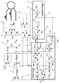
- the stator 1 of a brushless electric machine for example a synchronous motor with permanent magnet rotor, is operated by a converter 2 operating on the basis of pulse width modulation (PWM) with a three-phase three-phase current.
- PWM pulse width modulation
- the two phase currents i 1 , i 2 are tapped or measured by the stator, which are mapped in a 3-to-2 phase transformation unit 3 to a stator-related, orthogonal ⁇ , ⁇ coordinate system.
- two ⁇ , ⁇ vector components i ⁇ , i ⁇ representing the stator current are generated and output to a second, downstream coordinate transformation unit 4.
- This is adapted to a coordinate transformation from the stator-related ⁇ , ⁇ coordinate system to the rotor-related d, q coordinate system with the output of the current longitudinal and Quervektorkomponenten i d , iq make.
- the longitudinal and transverse vector components i d , iq from the stator current are fed as actual values to the series current and cross-current regulators I d , I q for the setpoint / actual value comparison with corresponding longitudinal and cross- current setpoint values i dsoll , i qsoll .
- the longitudinal current setpoint input i dsoll is set to zero, while the cross-flow controller receives the setpoint input I qsoll from an upstream speed controller 5.
- a determined electrical angle ⁇ em is output from the tracking controller 6 and supplied to the second transformation unit 4 and to a third transformation unit 7 complementary thereto.
- the third transformation unit 7 further receives the preset of the current regulators I d, I q longitudinal and transverse voltage vector components u g, u q and forms this u ⁇ , u ⁇ in the stator- ⁇ , ⁇ coordinate system with the specified voltage vector components from.
- the latter voltage vector components are received by a downstream, 2-to-3-phase transformation unit 8, which converts the voltage specification into three phases u 1 , u 2 , u 3 corresponding to the three-phase system for the downstream converter 2.
- FIG. 1 is the tracking controller 6 upstream of a motor modeling module 9.
- This has input interfaces 10 for the determined rotational speed ⁇ em , 11 for the measured longitudinal and transverse currents i d , iq and 12 mapped into the d, q coordinate system for the longitudinal and transverse voltages u d given in the d, q coordinate system , u q up.
- the modeling module 9 has a first output interface 13 for the longitudinal voltage deviation ⁇ u d and a second output interface 14 for the transverse voltage deviation ⁇ u q .
- the determined speed ⁇ em which is supplied via the speed input interfaces 10 to the motor model 9, is weighted with a plurality of separate proportional elements whose gains correspond to the emf constant K E , the motor longitudinal inductance L d and the motor lateral inductance Lq. Furthermore, the input speed ⁇ em is still with a Signum member 15 weighted.
- the outputs of the inductance proportional elements L d , Lq are each connected to a dedicated multiplier M d , Mq.
- the second inputs of the multipliers M d , Mq are each connected to the corresponding one of the two current input interfaces 11 for longitudinal or transverse current i d , iq.
- the respective outputs of the multipliers M d , Mq are supplied to positive and negative voltage summers S d , S q respectively with a positive sign.
- a second input of the longitudinal or transverse voltage summing elements S d , Sq, the longitudinal or transverse voltage specifications u d , u q are also supplied via the voltage input interfaces 12, each with a positive sign.
- the two voltage summators S d , Sq each have an additional negative input (each with a negative sign), which a respective output of two upstream voltage Vorsummierglieder VS d and VSq for the summation of ohmic and inductive longitudinal or transverse voltage intermediate values is assigned, which are generated from the supplied via the current input interfaces 11 longitudinal and transverse currents.
- a proportional element with the amplification r corresponding to the ohmic motor resistance is used for this generation.
- the inductive elements or the longitudinal and transverse inductance L d , Lq, via respective differentiators sL d and sLq are included in the calculation of the intermediate voltage values.
- the inputs of the respective proportional elements r and differentiating elements sL d , sLq are connected to the respective current input interfaces 11.
- the outputs of the respective proportional elements r and of the respective differentiating elements sL d and sLq are then connected to the respective inputs of positive sign of the presumming devices VS d , VSq.
- FIG. 1 is the sign member 15 on the input side connected to the speed input interface 10 and the output side to the first input of a sign multiplier SM d . Its second input communicates with the output of the longitudinal voltage summing S d , and the output of the sign multiplier SM d is connected to the first output interface 13 for the longitudinal vector component ⁇ u d of the voltage deviation in combination. This allows the direction of the Involving the rotor of the electric machine in the calculation of the positional error.
- the EMF motor constant also flows via a proportional element 16 dimensioned with a corresponding gain.
- the EMF proportional element is connected on the input side to the speed input interface 10.
- the EMF proportional element 16 is connected to the negative input of an EMF summing element 17 whose positive input communicates with the output of the transverse voltage summing element Sq.
- the output of the EMF summer 17 goes directly to the second or quadrature deviation output interface 14 of the modeling module for outputting the velocity detection error to the downstream tracking controller 6.
- the tracking controller has two input interfaces 18, 19 for the longitudinal and transverse vector components ⁇ u d , ⁇ u q of the voltage deviation calculated in the modeling module 9.
- the longitudinal vector component corresponds to the attitude detection error, and the transverse vector component to the velocity detection error.
- the input interface 18 for the longitudinal voltage deviation ⁇ u d is fed directly to a proportional element 20 which is dimensioned with the proportional gain kp and is connected on the output side to the minus input of a first tracking summation element 21. Its plus input is connected internally in the tracking controller 6 directly to the input interface for the transverse voltage deviation ⁇ u q .
- the summation result is fed to a first integration element 22, which according to the invention is designed without a proportional component and is dimensioned on the basis of the emf constant K E and a time constant T ⁇ .
- the determined drive angular velocity or rotational speed ⁇ em which via a first tracking controller output interface 23 both to the machine modeling module 9 and to the velocity controller 5 as it were, is produced at its output by integrating the difference between the longitudinal and transverse voltage deviations over time Actual value or for comparison with a speed setpoint ⁇ soll and to calculate a default cross-flow value i qsoll to be performed.
- the determined drive speed ⁇ em is still internally processed in the tracking controller 6 with a second integration element 24, which calculates the electric drive position or angular position therefrom in a manner known per se and outputs it via the second tracking controller output interface 25.
- the electric drive position ⁇ em output via the second tracking controller output interface, is used to control or control the two ⁇ , ⁇ / d, q and d, q / ⁇ , ⁇ transformation units 4, 7, respectively
- the tracking controller according to the invention is already characterized solely by the simplified I-structure with two integrally successive integrators 22, 24.
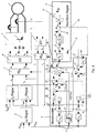
- FIG. 2 is opposite FIG. 1 modified control or drive control system shown.
- the modifications are manifested above all in the blocks labeled by AD of the modeling module 9 and a third input interface 28 of the tracking controller 6.
- FIG. 2 are compared to the modeling arrangement after FIG. 1 the local inductance differentiating elements sL d , sLq replaced by inductance proportional terms A, D with the longitudinal or transverse inductance L d , Lq as the respective gain factor.
- the inductance proportional element A can still be connected in series connection, a further proportional element according to the above-mentioned in connection with the tracking controller 6 proportional element 20 (interpretable as "Lageregul michsglied") upstream or downstream.
- the output of the inductance proportional element A responsible for the longitudinal vector component is followed by a multiplier B, the second input of which is connected to the output of the aforementioned sign element 15, thereby taking into account the direction of rotor rotation or linear motion.
- the output of the multiplier A is passed to the positive input of an inductance summing 26, the second input, linked with a negative sign, to the output of the responsibility for the cross-flow component inductance proportional element D is connected.
- the resulting at the output of the inductance summer 26 differential value is still weighted with an associated proportional element C, the output connected to the third output interface 27 for the Indukt foundedsbondsabweichung ⁇ u L and dimensioned according to the machine-specific emf constant K E and the time constant T ⁇ .
- the value for the inductance voltage deviation ⁇ u L output at the third output interface 27 or at the output of the proportional element C is input to the third input interface 28 of the tracking controller 6.
- the voltage deviation ⁇ u L in the tracking controller is fed to a second tracking summation element 29 with a positive sign.
- the second input of the second tracking summation element 29 is also assigned the output of the first integration element 22 with a positive sign.
- the output of the second tracking summation element 29 is connected directly to the first tracking controller output interface 23 for the feedback of the determined drive speed ⁇ em and to the input of the second integration element 24 for determining and outputting the drive position ⁇ em to the second and third coordinate transformation units 4, 7 in connection.
- FIGS. 1 and 2 is common that the position and speed determination "sensory" alone via measurements of the stator currents I 1 , I 2 takes place.
Landscapes
- Engineering & Computer Science (AREA)
- Power Engineering (AREA)
- Control Of Motors That Do Not Use Commutators (AREA)
- Control Of Ac Motors In General (AREA)
- Control Of Electric Motors In General (AREA)
Abstract
Description
Die Erfindung betrifft ein Verfahren zur Ermittlung der Antriebs-Geschwindigkeit und -Lage eines Permanentmagnet-Läufers einer elektrischen bürstenlosen Maschine. Dieses Verfahren ist insbesondere zum Einsatz in einen Antriebsregelkreis geeignet. Für das Verfahren werden mehrphasige Strommessungen an der Maschine verwendet, deren Messwerte in Abhängigkeit von der ermittelten Lage in ein rotorbezogenes d,q-Koordinatensystem zu einer Längsstrom-Vektorkomponente und einer Querstrom-Vektorkomponente transformiert werden. Zusammen mit der ermittelten (elektrischen) Drehzahl werden die Längs- und Quervektorkompenten vom Strom und einer vorgegebenen Spannung als Eingangsvariable einem mathematischen Modell von der elektrischen Maschine zugeführt. Das Maschinenmodell generiert eine erste Ausgangsvariable und eine zweite Ausgangsvariable, wobei die erste Ausgangsvariable im d,q-Koordinatensystem der d- bzw. Längsvektorkomponente sowie eines Lageermittlungsfehlers und die zweite Ausgangsvariable im d,q-Koordinatensystem der q- bzw. Querkomponente sowie einem Geschwindigkeitsermittlungsfehler entsprechen. Die beiden Ausgangsvariablen werden einem Nachführregler zu Ermittlung und Ausgabe der Geschwindigkeit, insbesondere elektrischen Drehzahl, und der Lage, insbesondere des elektrischen Winkels zugeführt. Die Erfindung betrifft ferner zur Durchführung dieses Verfahrens geeignete Lage- und/oder Geschwindigkeits-Ermittlungseinrichtung, Maschinen-Modellierungsmodul und Geschwindigkeits-Nachführregler gemäß den jeweiligen ersten Teilen/Oberbegriffen der nebengeordneten, unabhängigen Ansprüche 8, 12 und 15.The invention relates to a method for determining the drive speed and position of a permanent magnet rotor of an electric brushless machine. This method is particularly suitable for use in a drive control loop. The method uses multiphase current measurements on the machine whose measured values are transformed into a longitudinal current vector component and a cross-current vector component as a function of the position determined in a rotor-related d, q coordinate system. Together with the determined (electrical) speed, the longitudinal and transverse vector components of the current and a given voltage as input variables are fed to a mathematical model of the electric machine. The machine model generates a first output variable and a second output variable, wherein the first output variable in the d, q coordinate system corresponds to the d or longitudinal vector component and a position detection error, and the second output variable in the d, q coordinate system corresponds to the q or transverse component and a velocity detection error , The two output variables are fed to a tracking controller for determining and outputting the speed, in particular electrical speed, and the position, in particular the electrical angle. The invention further relates to the implementation of this method suitable position and / or speed detection device, machine modeling module and speed tracking controller according to the respective first parts / preambles of the independent
Zur Ermittlung der Lage und Geschwindigkeit des Permanentmagnet-Läufers bei einem elektrischen, bürstenlosen Antriebsmotor wird in der AT-Fachzeitschrift "
Diese
Ein System zur Ermittlung der Antriebs-Lage und/oder Geschwindigkeit bei einer elektrischen, bürstenlosen Maschine, insbesondere Synchronmotor, mit Permanentmagnet-Läufer etwa der anfangs im ersten Absatz genannten Art ist bekannt, vgl. Fachartikel von
Der Erfindung liegt die Aufgabe zugrunde, dem gegenüber das Antriebs-Lage- und Antriebs-Geschwindigkeits-Ermittlungssystem in seinem strukturellen Aufbau zu vereinfachen. Zur Lösung wird auf das im Anspruch 1 angegebene Ermittlungsverfahren, auf die im Anspruch 8 angegebene Ermittlungseinrichtung, auf das im Anspruch 12 angegebene Maschinen-Modellierungsmodul sowie auf den im Anspruch 15 angegebenen Nachführregler verwiesen. Optionale, vorteilhafte Weiterbildungen der Erfindung ergeben sich aus den abhängigen Ansprüchen.The object of the invention is to simplify the drive position and drive speed determination system in its structural design. For the solution, reference is made to the determination method specified in
Zwar arbeitet gemäß dem erfindungsgemäßen Verfahren das Maschinenmodell noch mit der Ausgabe einer dritten Abweichungsvariablen an den Nachführregler; jedoch wird dabei die dritte Ausgangsvariable über einfach zu realisierende Rechenschritte erzeugt, die lediglich Gewichtungen durch Proportionalglieder mit Induktivitäts-Festwerten und Summierungen/Differenzbildungen umfassen und mithin mit rechentechnisch einfachen und schnell ablaufenden Funktionskomponenten wie P-Glieder und Summierstellen zu realisieren sind. Mithin lässt sich mit dem erfindungsgemäßen Verfahren der Vorteil einer Effizienzsteigerung erzielen, zumal weder eine zeitliche Differenzierung von Strömen noch zusätzliche phasenverbrauchende Filter wie z. B. die oben beim Stand der Technik verwendeten Tiefpass-Filter notwendig sind.Although according to the inventive method, the machine model still works with the output of a third deviation variable to the tracking controller; however, the third output variable becomes simply over realizing computational steps generated, which include only weightings by proportional terms with inductance fixed values and summations / difference formations and thus can be implemented with computationally simple and fast-running functional components such as P-members and summation. Consequently, can be achieved with the inventive method, the advantage of an increase in efficiency, especially since neither a temporal differentiation of streams nor additional phase-consuming filter such. For example, the low-pass filters used in the prior art are necessary.
Zweckmäßig werden im Rahmen des Maschinenmodells die beiden Wichtungsergebnisse (Strom-Längskomponente gewichtet mit Längsinduktivität und Strom-Querkomponente gewichtet mit Querinduktivität) entsprechend einer maschinenspezifischen EMK-Konstante oder einer Zeitkonstante modifiziert. Mit besonderem Vorteil wird dann im Nachführregler eine Integration mit den genannten Konstanten als Integrationsparameter über eine Differenz durchgeführt, die zwischen dem Lage- und dem Geschwindigkeitsermittlungsfehler ("Lageabweichung" beziehungsweise "Geschwindigkeitsabweichung") bzw. den entsprechenden Längs- und Querkomponenten der Spannungsabweichung gebildet ist.The two weighting results (weighted longitudinal component weighted with longitudinal inductance and current-transverse component weighted with transverse inductance) are suitably modified within the scope of the machine model in accordance with a machine-specific emf constant or a time constant. With particular advantage, an integration with the specified constants as an integration parameter is then carried out in the tracking controller via a difference formed between the positional and the velocity detection error ("positional deviation" or "speed deviation") or the corresponding longitudinal and transverse components of the voltage deviation.
In weiterer Ausgestaltung der Erfindung wird die dem Nachführregler zugeführte dritte Ausgangsvariable mit einem Integrationsergebnis über eine Differenz summiert oder sonst wie verknüpft, welche Differenz aus dem Unterschied zwischen des Lageermittlungsfehlers und des Geschwindigkeitsermittlungsfehlers gebildet wird. Gegebenenfalls ist der Lageermittlungsfehler vorher noch proportional verstärkt worden. Das Verknüpfungsergebnis kann dann aus dem Nachführregler als ermittelte Geschwindigkeit ausgegeben werden. Es wird der Vorteil einer Vereinfachung der Struktur des Nachführreglers erzielt, indem gegenüber reinen Integriergliedern komplexere Proportional- und Integralglieder vermieden sind.In a further embodiment of the invention, the third output variable fed to the tracking controller is summed with an integration result by means of a difference or otherwise linked, which difference is formed from the difference between the position determination error and the speed determination error. If necessary, the position determination error has previously been amplified proportionally. The result of the combination can then be output from the tracking controller as the determined speed. The advantage of simplifying the structure of the tracking controller is achieved by avoiding more complex proportional and integral terms compared to pure integrators.
Da gemäß einer Erfindungsvariante bei der Zuführung der dritten Ausgangsvariablen in den Nachführregler sowohl das dortige Proportionalglied (interpretierbar als "Lageregler") als auch ein reines erstes Integrationsglied ohne Proportionalanteil (interpretierbar als "Geschwindigkeitsregler") über eine diesen nachgeordnete Summierstelle übersprungen werden, ist es zweckmäßig, die (übersprungene) Proportionalverstärkung bereits im Maschinenmodell bei der Bildung der dritten Ausgangsvariablen zur Auswirkung zu bringen. Dies lässt sich realisieren, indem die Strom-Längsvektorkomponente nach Einführung in das Maschinenmodell darin mit dieser Proportionalverstärkung bzw. -faktor gewichtet wird.Since according to a variant of the invention in the supply of the third output variable in the tracking controller both the local proportional element (interpretable as a "position controller") and a pure first Integrator without proportional component (interpretable as "speed controller") are skipped over a subordinate summing this subordinate, it is appropriate to bring the (skipped) proportional gain already in the machine model in the formation of the third output variables to effect. This can be realized by weighting the current longitudinal vector component with this proportional gain after introduction into the machine model therein.
Weitere Einzelheiten, Merkmale, Merkmalskombinationen, Vorteile und Wirkungen auf der Basis der Erfindung ergeben sich aus der nachfolgenden Beschreibung bevorzugter Ausführungsformen der Erfindung sowie aus den Zeichnungen. Diese zeigen in jeweils schematischer Blockschaltbild-Darstellung in
-
Figur 1 -
Figur 2
-
FIG. 1 and as a conceptual starting point, a drive control loop with a motor model and after switched, according to the invention Nachführregler, for better understanding of the invention, the machine model still contains the adverse direct time derivatives of currents; -
FIG. 2 a drive control circuit with inventively designed motor model and correspondingly adapted tracking controller.
Gemäß
Gemäß
Gemäß
Gemäß
Gemäß
Gemäß
In
Gemäß
Gemäß
Den beiden Ausführungsbeispielen gemäß
- 11
- Statorstator
- 22
- Umrichterinverter
- 33
- 3-zu-2 Phasen-Transformationseinheit3-to-2 phase transformation unit
- 44
- zweite Koordinaten-Transformationseinheitsecond coordinate transformation unit
- iα, iβ i α , i β
- Stromkomponenten im statorbezogenen α, β-KoordinatensystemCurrent components in the stator-related α, β coordinate system
- idsoll, iqsoll i dsoll , i qsoll
- Längs- bzw. QuerstromsollwertLongitudinal or cross current setpoint
- Id, Iq I d , I q
- Längs- und QuerstromreglerLongitudinal and cross flow regulator
- 55
- Geschwindigkeitsreglercruise control
- 66
- Nachführreglertracking regulator
- ωsoll ω should
- DrehzahlsollwertSpeed setpoint
- ωem ω em
- ermittelte elektrische Drehzahldetermined electrical speed
- ϕem φ em
- ermittelte elektrische Winkellagedetermined electrical angular position
- 77
- dritter Koordinaten-Transformationseinheitthird coordinate transformation unit
- ud, uq u d , u q
- Längs- bzw. QuerspannungsvorgabenLongitudinal or transverse voltage specifications
- uα, uβ u α , u β
- Spannungsvorgabe im α, β-Koordinatensystem (statorbezogen)Voltage specification in α, β coordinate system (stator related)
- 88th
- 2-zu-3 Phasen-Transformationseinheit2-to-3 phase transformation unit
- u1, u2, u3 u 1 , u 2 , u 3
- Spannungsvorgabe für drei PhasenVoltage specification for three phases
- 99
- Motor-ModellierungsmodulMotor modeling module
- 1010
- Drehzahl-EingangsschnittstellenSpeed input interfaces
- 1111
- Strom-EingangsschnittstellenPower input interface
- 1212
- Spannungs-EingangsschnittstelleVoltage input interface
- 13, 1413, 14
- erste und zweite Ausgangsschnittstelle für intern berechnete Spannungsabweichungs-Vektorkomponentenfirst and second output interfaces for internally calculated voltage deviation vector components
- KE K E
- EMK-KonstanteEMF constant
- 1515
- SignumsgliedSignum link
- Md, Mq M d , M q
- Multipliziergliedermultipliers
- Sd, Sq S d , S q
- SpannungssummiergliederSpannungssummierglieder
- VSd, VSq VS d , VS q
- VorsummiergliederVorsummierglieder
- rr
- Proportionalglied für MotorwiderstandProportional element for motor resistance
- sLd, sLq sL d , sL q
- Längs-, Querstrom-DifferenziergliedLongitudinal, cross-flow differentiator
- SMd SM d
- Vorzeichen-MultipliziergliedSign multiplier
- Δud Δu d
- LängsvektorkomponenteDirect vector component
- Δuq Δu q
- QuervektorkomponenteCross vector component
- 1616
- EMK-ProportionalgliedEMF proportional element
- 1717
- EMK-SummiergliedEMF summing
- 18, 1918, 19
- Eingangsschnittstellen für Längs- und QuerspannungsabweichungInput interfaces for longitudinal and transverse voltage deviation
- 2020
- Proportionalgliedproportional element
- 2121
- erstes Nachführ-Summiergliedfirst tracking summer
- 2222
- erstes Integrationsgliedfirst integrator
- 2323
- erste Nachführregler-Ausgangsschnittstellefirst tracking controller output interface
- 2424
- zweites Integrationsgliedsecond integration element
- 2525
- zweite Nachführregler-Ausgangsschnittstellesecond tracking controller output interface
- A,DA, D
- Induktivitäts-ProportionalgliederInductance proportional elements
- BB
- Multipliziergliedmultiplier
- 2626
- Induktivitäts-SummiergliedInductance summing
- CC
- Proportionalgliedproportional element
- 2727
- dritte Ausgangsschnittstellethird output interface
- 2828
- dritte Eingangsschnittstellethird input interface
- 2929
- zweites Nachführ-Summiergliedsecond tracking totalizer
Claims (18)
- Method of determining the electrical drive speed (ωem) and drive position (φem) of a permanent magnet rotor of a brushless electric linear or rotary machine in particular for a drive control circuit, using multiphase current measurements of the machine, whose measured values (i1, i2) are transformed as a function of the position determined (φem) into a rotor-specific d,q-coordinate system to a longitudinal current vector component (id) and a transverse current vector component (iq), and the longitudinal and transverse vector components from the current (id, iq) and a predetermined voltage (ud, uq) are supplied together with the determined speed (ωem) as an input variable to a mathematical machine model (9), and the machine model (9) generates a first output variable (Δnd) and a second output variable (Δuq), wherein the first output variable (Δud) in the d,q-coordinate system corresponds to the d- or longitudinal vector component and to a position determination error, and the second output variable (Δuq) in the d,q-coordinate system corresponds to the q- or transverse vector component and to a speed determination error, and the two output variables (Δud, Δuq) are supplied to a compensating control (6) for determining and outputting the position (φem) and/or speed (ωem), characterised in that from the machine model a third output variable (ΔuL) is computed in thata) the longitudinal and the transverse vector components from the current (id, iq) are each weighted with a series and a shunt inductance (Ld, Lq) respectively of the machine,b) and the third output variable (ΔuL) is formed from the differential between the two weighting results,wherein the third output variable (ΔuL) is supplied to the compensating control (6) for processing in order to determine the position (φem) and speed (ωem).
- Method according to claim 1, characterised in that the current longitudinal component (id) weighted with the series inductance (Ld) is influenced with the polarity sign or direction of the speed (ωem) determined.
- Method according to claim 1 or 2, characterised in that in the machine model (9) the differential obtained from the two weighting results is influenced by a machine-specific electromotive force (emf) constant (KE) and/or a time constant (Tω).
- Method according to claim 3, characterised in that in the machine model (9) the differential is divided by the emf-constant (KE) and/or the time constant (Tω) and in the compensating control (6) the same emf-constant (KE) and/or the same time constant (Tω) are used as parameters for the integration of a differential which is obtained from the optionally proportionally (kp) amplified position determination error (Δud) and of the speed determination error (Δuq).
- Method according to one of the preceding claims, characterised in that in the compensating control (6) the third output variable (ΔuL) supplied thereto is integrated or is otherwise linked to the result of an integration (22) of a differential (21) which is obtained from the optionally proportionally (kp) amplified position determination error (Δud) and of the speed determination error (Δuq), and the result of the link is used and/or output as the speed (ωem) determined.
- Method according to claim 5, characterised in that the differential (21) is formed in the compensating control (6) and/or is subjected to integration (22) without a proportional component.
- Method according to one of the preceding claims, characterised in that in the machine model (9) the current longitudinal vector component (id) is weighted with a proportional factor (kp) which is used in the compensating control (6) to regulate the position determination error (Δud).
- Device for determining the electrical drive position (Δem) and drive speed (ωem) of a permanent magnet rotor of a brushless electric linear or rotary machine, in particular for a drive control circuit, suitable for carrying out the determination method according to one of the preceding claims, having the following functional components:a) a machine modelling module (9) realised with switching and/or program technology and having:aa) input interfaces (10, 11, 12) for machine longitudinal and transverse vector components (id, iq; ud, uq), transformed into a rotor-specific d,q-coordinate system, from the stator current (i1, i2) and a predetermined voltage transformed into a rotor-specific d, q-coordinate system and for the speed (ωem) determined,ab) and at least two output interfaces (13, 14) for vector components (Δud, Δuq), of an internally computed voltage deviation, transformed into the d, q-coordinate system ,b) with a compensating control (6) realised with switching and/or program technology for outputting the position and/or speed, which control is connected:characterised in that the machine modelling module (9) has at least one further third output interface (27) for an inductance voltage deviation (ΔuL) and is formed for the purpose of evaluating by means of proportional members (A, D) the input values for the current longitudinal and transverse vector components (id, iq) with fixed values for a series or shunt inductance (Ld, Lq) respectively of the stator (1) or of the machine, and for forming by means of an inductance integrating member (26) the differential from the inductively evaluated input values and outputting this via the third output interface (27), to which the compensating control (6) is connected on the input side for receiving the differential and is formed for the purpose of processing the differential in order to determine the speed (ωem) and outputting the latter to the speed input interface (10) of the modelling module (9).ba) on the input side to the at least two output interfaces (13, 14) of the modelling module (9)bb) and on the output side to the speed input interface (10) of the modelling module (9),
- Determining device according to claim 8, characterised in that in the machine model (9) the input interface (11) for the current longitudinal vector component (id) is supplied to a proportional member (A) with a proportional amplification (kp), and in the compensating control (6) is disposed a proportional member (20) with the same or similar proportional amplification (kp) for weighting of the position determination error (Aud).
- Determining device according to claim 9, characterised in that in the machine model the proportional member with the proportional amplification (kp) is arranged connected in series with an inductance proportional member (A) dimensioned according to the series inductance fixed value (Ld).
- Determining device according to claim 8, 9, or 10, characterised in that the output of the inductance integration member (26) is connected to the third output interface (27) via a proportional member (C), which is dimensioned according to an emf-constant (KE) and/or a time constant (Tω), and in the compensating control (6) for processing therein of an optionally weighted or otherwise treated combination of the d, q-vector components (Δud, Δuq) of the voltage deviation supplied from the upstream modelling module (9), a first integration member (22) is disposed, which is set according to the same or a similar emf-constant (KE) and/or time constant ((Tω).
- Machine modelling module for a brushless electric linear or rotary machine with permanent magnet rotor, suitable for use in the determining device according to claim 8 or 9, havinga) input interfaces (11) for a machine longitudinal and transverse vector component (id, iq, ud, uq), transformed into a rotor-specific d-q-coordinate system, from the current and a predetermined voltage and for an externally determined machine speed (ωem),b) and having at least two output interfaces (13, 14) for longitudinal and transverse vector components (Δud, Δuq), of an internally computed voltage deviation, transformed into the d, q-coordinate system,c) and having plural proportional members (r, A, D) for weighting the current vector components (id, iq) with an ohmic stator resistance or machine resistance (r) and one or more stator or machine inductances (Ld, Lq),characterised by at least one further third output interface (27) for an inductance voltage deviation (ΔuL), for generating which a series and shunt inductance proportional member (A, D) is provided, having amplifications according to a series or shunt inductance (Ld, Lq) respectively and being connected on the input side to the input interfaces (11) for the current longitudinal and transverse vector components (id, iq), and the two proportional member outputs are directly or indirectly coupled to the inputs of an inductance integration member (26), and the output of the inductance integration member (26) is coupled directly or indirectly to the third output interface (27).
- Machine modelling module according to claim 12, characterised by a polarity sign or signum member (15), which is connected at its input to the input interface (10) for the externally determined machine speed (ωem) and on the output side is linked via a multiplying member (B) to the output of a proportional member (A, D), which weights the current longitudinal or transverse vector component (id, iq) with the series or shunt inductance (Ld, Lq).
- Machine modelling module according to claim 12 or 13, characterised in that the output of the inductance integration member (26) is supplied via a proportional member (C), whose proportional amplification is determined via fixed values for a machine-specific emf-constant (KE) and/or time constant (Tω), to the third output interface (27).
- Compensating control (6) for carrying out the method or for use in the determining device according to one of the preceding claims, having the following features:a) having at least two input interfaces (18, 19) for longitudinal and transverse vector components (Δud, Δuq), of an externally computed and supplied voltage deviation, transformed into the d, q-coordinate system,b) having at least one output interface (23) for an internally determined drive speed (ωem),c) having a proportional member (20, kp) whose input is connected to the input interface (18) for the longitudinal vector component (Δud) of the externally computed voltage deviation or position determination error (Δu) respectively,d) having a first compensating integration member (21), whose first input is connected to the output of the proportional member (20, kp) and whose second input is connected via the second input interface (19) to the transverse vector component (Δuq) of the voltage deviation or of the speed determination error respectively,characterised by at least one further third input interface (28) for an inductance voltage deviation (ΔuL) supplied externally, wherein the third input interface (28) is connected to the first input of a linking member whose second input indirectly or directly detects the output of the first compensating integration member (21), and whose output is measurable via the at least one output interface (23) for the drive speed (ωem).
- Compensating control according to claim 15, characterised in that the linking member is formed as a second compensating integration member (29) arranged indirectly or directly downstream of the first compensating integration member (21).
- Compensating control according to claim 15 or 16, characterised in that solely one integration member (22) is interposed between the first compensating integration member (21) and the linking or second compensating integration member (29).
- Compensating control according to claim 17, characterised in that the integration member (22) is dimensioned without a proportional component and/or on the basis of the emf-constant (KE) and/or time constant (Tω).
Priority Applications (7)
| Application Number | Priority Date | Filing Date | Title |
|---|---|---|---|
| AT07113231T ATE463073T1 (en) | 2007-07-26 | 2007-07-26 | SYSTEM FOR DETERMINING POSITION AND SPEED OF A PERMANENT MAGNET RUNNER OF AN ELECTRICAL MACHINE |
| DE502007003311T DE502007003311D1 (en) | 2007-07-26 | 2007-07-26 | System for determining the position and speed of a permanent magnet rotor of an electrical machine |
| EP07113231A EP2019482B1 (en) | 2007-07-26 | 2007-07-26 | System for determining the position and speed for a permanent magnet rotor of an electric machine |
| DE202008009574U DE202008009574U1 (en) | 2007-07-26 | 2008-07-16 | System for determining the position and speed of a permanent magnet rotor of an electrical machine |
| US12/177,182 US7999498B2 (en) | 2007-07-26 | 2008-07-22 | System for estimation of position and speed in a permanent magnet rotor of an electrical motor |
| CN2008101443425A CN101399514B (en) | 2007-07-26 | 2008-07-25 | System for determining the position and speed for a permanent magnet rotor of an electric machine |
| JP2008191634A JP5501580B2 (en) | 2007-07-26 | 2008-07-25 | Position and speed estimation system in permanent magnet rotor of electric motor |
Applications Claiming Priority (1)
| Application Number | Priority Date | Filing Date | Title |
|---|---|---|---|
| EP07113231A EP2019482B1 (en) | 2007-07-26 | 2007-07-26 | System for determining the position and speed for a permanent magnet rotor of an electric machine |
Publications (2)
| Publication Number | Publication Date |
|---|---|
| EP2019482A1 EP2019482A1 (en) | 2009-01-28 |
| EP2019482B1 true EP2019482B1 (en) | 2010-03-31 |
Family
ID=38562827
Family Applications (1)
| Application Number | Title | Priority Date | Filing Date |
|---|---|---|---|
| EP07113231A Active EP2019482B1 (en) | 2007-07-26 | 2007-07-26 | System for determining the position and speed for a permanent magnet rotor of an electric machine |
Country Status (6)
| Country | Link |
|---|---|
| US (1) | US7999498B2 (en) |
| EP (1) | EP2019482B1 (en) |
| JP (1) | JP5501580B2 (en) |
| CN (1) | CN101399514B (en) |
| AT (1) | ATE463073T1 (en) |
| DE (2) | DE502007003311D1 (en) |
Families Citing this family (18)
| Publication number | Priority date | Publication date | Assignee | Title |
|---|---|---|---|---|
| US8248009B2 (en) * | 2008-11-17 | 2012-08-21 | Rockwell Automation Technologies, Inc. | Motor controller having integrated communications configurations |
| US8375809B2 (en) * | 2010-03-02 | 2013-02-19 | Hamilton Sundstrand Corporation | Load monitoring for electromechanical systems |
| EP2421146B1 (en) * | 2010-08-16 | 2015-02-11 | Baumüller Nürnberg GmbH | Device and method for identifying magnetomechanical parameters of an alternating current synchronous motor without using a rotary encoder |
| GB2489434A (en) * | 2011-03-25 | 2012-10-03 | Technelec Ltd | Controlling an electrical machine with an observer |
| EP2552014A3 (en) | 2011-07-28 | 2016-08-17 | Vestas Wind Systems A/S | A method of position sensorless control of an electrical machine |
| EP2552015B1 (en) | 2011-07-28 | 2018-05-16 | Vestas Wind Systems A/S | A method of position sensorless control of an electrical machine |
| CN102507189B (en) * | 2011-09-23 | 2014-04-02 | 奇瑞汽车股份有限公司 | Testing method and testing system of position of mixed power motor rotor |
| DE202012000091U1 (en) | 2012-01-05 | 2012-03-16 | Frank Mayer | Device for controlling an induction machine on a direct converter up to zero speed |
| US8823301B2 (en) | 2012-11-05 | 2014-09-02 | Whirlpool Corporation | Method and device for detecting rotor position in a permanent magnet synchronous motor-driven washing machine |
| CN103346727B (en) * | 2013-07-27 | 2016-01-20 | 湖北立锐机电有限公司 | Be applied to angle tracking observer and its implementation of PMSM position-sensorless control |
| US9722522B2 (en) | 2014-04-02 | 2017-08-01 | Canrig Drilling Technology Ltd. | Method for controlling torque in permanent magnet motor drives |
| US10655377B2 (en) | 2016-04-21 | 2020-05-19 | Westinghouse Air Brake Technologies Corporation | Method and system for detecting an obstruction of a passenger door |
| JP6661509B2 (en) * | 2016-10-04 | 2020-03-11 | 日立オートモティブシステムズ株式会社 | Control device and control method for brushless motor |
| JP6757226B2 (en) * | 2016-10-07 | 2020-09-16 | 株式会社マキタ | Electric tool |
| GB2579633B (en) * | 2018-12-07 | 2023-02-01 | Zf Automotive Uk Ltd | A method of characterising a permanent magnet synchronous motor |
| CN112968643B (en) * | 2021-02-01 | 2022-08-26 | 南京邮电大学 | Based on self-adaptation extension H ∞ Filtering brushless direct current motor parameter identification method |
| CN115459663A (en) | 2021-05-20 | 2022-12-09 | 台达电子工业股份有限公司 | Motor control method |
| JP7362003B2 (en) * | 2021-08-24 | 2023-10-16 | 三菱電機株式会社 | Rotating machine control device |
Family Cites Families (8)
| Publication number | Priority date | Publication date | Assignee | Title |
|---|---|---|---|---|
| JP3411878B2 (en) * | 2000-03-06 | 2003-06-03 | 株式会社日立製作所 | Method for estimating rotor position of synchronous motor, control method without position sensor, and control device |
| JP3719910B2 (en) * | 2000-05-30 | 2005-11-24 | 株式会社東芝 | Motor control device |
| JP3651595B2 (en) * | 2001-12-13 | 2005-05-25 | 株式会社東芝 | Inverter device for washing machine and inverter device for washing dryer |
| JP2004015858A (en) * | 2002-06-04 | 2004-01-15 | Meidensha Corp | Sensorless control system of pm motor position |
| JP3972124B2 (en) * | 2002-07-10 | 2007-09-05 | 株式会社日立製作所 | Synchronous motor speed control device |
| JP4230276B2 (en) | 2003-05-19 | 2009-02-25 | 本田技研工業株式会社 | Brushless DC motor control device |
| CN1767356A (en) * | 2004-10-27 | 2006-05-03 | 乐金电子(天津)电器有限公司 | DC brushless motor speed control device and its method |
| CN100413207C (en) * | 2006-11-17 | 2008-08-20 | 清华大学 | Vector control system of alien frequencies power supplied permanent magnet synchronous motor |
-
2007
- 2007-07-26 DE DE502007003311T patent/DE502007003311D1/en active Active
- 2007-07-26 EP EP07113231A patent/EP2019482B1/en active Active
- 2007-07-26 AT AT07113231T patent/ATE463073T1/en active
-
2008
- 2008-07-16 DE DE202008009574U patent/DE202008009574U1/en not_active Expired - Lifetime
- 2008-07-22 US US12/177,182 patent/US7999498B2/en active Active
- 2008-07-25 JP JP2008191634A patent/JP5501580B2/en not_active Expired - Fee Related
- 2008-07-25 CN CN2008101443425A patent/CN101399514B/en active Active
Also Published As
| Publication number | Publication date |
|---|---|
| DE202008009574U1 (en) | 2009-03-12 |
| JP5501580B2 (en) | 2014-05-21 |
| CN101399514B (en) | 2012-09-05 |
| US7999498B2 (en) | 2011-08-16 |
| US20090030645A1 (en) | 2009-01-29 |
| CN101399514A (en) | 2009-04-01 |
| EP2019482A1 (en) | 2009-01-28 |
| ATE463073T1 (en) | 2010-04-15 |
| JP2009033963A (en) | 2009-02-12 |
| DE502007003311D1 (en) | 2010-05-12 |
Similar Documents
| Publication | Publication Date | Title |
|---|---|---|
| EP2019482B1 (en) | System for determining the position and speed for a permanent magnet rotor of an electric machine | |
| EP2023479B1 (en) | System for seamless velocity and/or location determination including standstill for a permanent magnet rotor of an electric machine | |
| DE60024222T2 (en) | Method for estimating the rotor position of a synchronous motor, method for controlling a sensorless synchronous motor and a controller for a synchronous motor | |
| DE102007061905B4 (en) | Highly responsive permanent magnet motor control | |
| DE60224021T2 (en) | Control unit for an electric motor | |
| DE10206410A1 (en) | Rotor angle detection apparatus for brushless DC motor, determines sine and cosine reference value from current values detected by current detectors connected to three phase armature, for calculating rotor angle | |
| EP0127158B1 (en) | Method and apparatus to derive the flux vector of an induction machine from the stator current and the stator voltage, and application thereof | |
| EP2226929B1 (en) | Plausibility monitoring system for movement monitoring on an electrical drive device | |
| DE112010001465T5 (en) | AC motor control device and AC motor driver system | |
| DE10206191B4 (en) | Method for field-oriented control of a permanent-magnet synchronous machine with reluctance torque | |
| DE112008003590B4 (en) | Magnetic pole position estimation method for AC synchronous motor | |
| DE102008058872A1 (en) | Method and system for sensorless control of an electric motor | |
| DE10330791A1 (en) | Vector-oriented control system for synchronous machines with permanent magnets using an observer for the parameters of an open control loop | |
| DE112004002619T5 (en) | Motor control device | |
| DE102013207121A1 (en) | System for controlling a controlled variable of a rotating machine | |
| WO2016207383A1 (en) | Method for determining current-dependent and/or rotational angle position-dependent characteristic variables of an electrical machine, and frequency converter | |
| DE112020005654T5 (en) | ENGINE DRIVE EQUIPMENT, OUTDOOR UNIT OF AN AIR CONDITIONING SYSTEM INCLUDING SAME, AND ENGINE DRIVE CONTROL METHOD | |
| EP2144362B1 (en) | Method and assembly for observing the drive speed of a permanent magnet rotor in a drive control loop | |
| DE102008058739B4 (en) | Method for field-oriented operation of a sensorless asynchronous machine to standstill | |
| DE102019116339B4 (en) | Motor control device | |
| EP2619900A1 (en) | Method for controlling an asynchronous machine having a converter in a manner that is optimal for (copper) loss | |
| DE102008045622B4 (en) | Method for adapting a pole wheel orientation of a non-linear, sensorless, permanently excited synchro-machine | |
| DE102019130638A1 (en) | Device and method for controlling an engine | |
| DE112018008190T5 (en) | Rotary machine control device and electric vehicle control device | |
| DE102010021488A1 (en) | Method for copper loss-optimal control and/or regulation of asynchronous machine, involves computing and defining control value of regulator and adapting voltage vector to regulator over control value |
Legal Events
| Date | Code | Title | Description |
|---|---|---|---|
| PUAI | Public reference made under article 153(3) epc to a published international application that has entered the european phase |
Free format text: ORIGINAL CODE: 0009012 |
|
| AK | Designated contracting states |
Kind code of ref document: A1 Designated state(s): AT BE BG CH CY CZ DE DK EE ES FI FR GB GR HU IE IS IT LI LT LU LV MC MT NL PL PT RO SE SI SK TR |
|
| AX | Request for extension of the european patent |
Extension state: AL BA HR MK RS |
|
| 17P | Request for examination filed |
Effective date: 20090605 |
|
| GRAP | Despatch of communication of intention to grant a patent |
Free format text: ORIGINAL CODE: EPIDOSNIGR1 |
|
| AKX | Designation fees paid |
Designated state(s): AT BE BG CH CY CZ DE DK EE ES FI FR GB GR HU IE IS IT LI LT LU LV MC MT NL PL PT RO SE SI SK TR |
|
| GRAS | Grant fee paid |
Free format text: ORIGINAL CODE: EPIDOSNIGR3 |
|
| GRAA | (expected) grant |
Free format text: ORIGINAL CODE: 0009210 |
|
| AK | Designated contracting states |
Kind code of ref document: B1 Designated state(s): AT BE BG CH CY CZ DE DK EE ES FI FR GB GR HU IE IS IT LI LT LU LV MC MT NL PL PT RO SE SI SK TR |
|
| REG | Reference to a national code |
Ref country code: CH Ref legal event code: EP Ref country code: GB Ref legal event code: FG4D Free format text: NOT ENGLISH |
|
| REG | Reference to a national code |
Ref country code: IE Ref legal event code: FG4D |
|
| REF | Corresponds to: |
Ref document number: 502007003311 Country of ref document: DE Date of ref document: 20100512 Kind code of ref document: P |
|
| REG | Reference to a national code |
Ref country code: NL Ref legal event code: T3 |
|
| PG25 | Lapsed in a contracting state [announced via postgrant information from national office to epo] |
Ref country code: LT Free format text: LAPSE BECAUSE OF FAILURE TO SUBMIT A TRANSLATION OF THE DESCRIPTION OR TO PAY THE FEE WITHIN THE PRESCRIBED TIME-LIMIT Effective date: 20100331 |
|
| REG | Reference to a national code |
Ref country code: CH Ref legal event code: NV Representative=s name: SCHNEIDER FELDMANN AG PATENT- UND MARKENANWAELTE |
|
| LTIE | Lt: invalidation of european patent or patent extension |
Effective date: 20100331 |
|
| PG25 | Lapsed in a contracting state [announced via postgrant information from national office to epo] |
Ref country code: FI Free format text: LAPSE BECAUSE OF FAILURE TO SUBMIT A TRANSLATION OF THE DESCRIPTION OR TO PAY THE FEE WITHIN THE PRESCRIBED TIME-LIMIT Effective date: 20100331 Ref country code: LV Free format text: LAPSE BECAUSE OF FAILURE TO SUBMIT A TRANSLATION OF THE DESCRIPTION OR TO PAY THE FEE WITHIN THE PRESCRIBED TIME-LIMIT Effective date: 20100331 Ref country code: SI Free format text: LAPSE BECAUSE OF FAILURE TO SUBMIT A TRANSLATION OF THE DESCRIPTION OR TO PAY THE FEE WITHIN THE PRESCRIBED TIME-LIMIT Effective date: 20100331 Ref country code: PL Free format text: LAPSE BECAUSE OF FAILURE TO SUBMIT A TRANSLATION OF THE DESCRIPTION OR TO PAY THE FEE WITHIN THE PRESCRIBED TIME-LIMIT Effective date: 20100331 |
|
| REG | Reference to a national code |
Ref country code: IE Ref legal event code: FD4D |
|
| PG25 | Lapsed in a contracting state [announced via postgrant information from national office to epo] |
Ref country code: SE Free format text: LAPSE BECAUSE OF FAILURE TO SUBMIT A TRANSLATION OF THE DESCRIPTION OR TO PAY THE FEE WITHIN THE PRESCRIBED TIME-LIMIT Effective date: 20100331 Ref country code: CY Free format text: LAPSE BECAUSE OF FAILURE TO SUBMIT A TRANSLATION OF THE DESCRIPTION OR TO PAY THE FEE WITHIN THE PRESCRIBED TIME-LIMIT Effective date: 20100331 Ref country code: EE Free format text: LAPSE BECAUSE OF FAILURE TO SUBMIT A TRANSLATION OF THE DESCRIPTION OR TO PAY THE FEE WITHIN THE PRESCRIBED TIME-LIMIT Effective date: 20100331 Ref country code: ES Free format text: LAPSE BECAUSE OF FAILURE TO SUBMIT A TRANSLATION OF THE DESCRIPTION OR TO PAY THE FEE WITHIN THE PRESCRIBED TIME-LIMIT Effective date: 20100712 Ref country code: RO Free format text: LAPSE BECAUSE OF FAILURE TO SUBMIT A TRANSLATION OF THE DESCRIPTION OR TO PAY THE FEE WITHIN THE PRESCRIBED TIME-LIMIT Effective date: 20100331 |
|
| PG25 | Lapsed in a contracting state [announced via postgrant information from national office to epo] |
Ref country code: IS Free format text: LAPSE BECAUSE OF FAILURE TO SUBMIT A TRANSLATION OF THE DESCRIPTION OR TO PAY THE FEE WITHIN THE PRESCRIBED TIME-LIMIT Effective date: 20100731 Ref country code: CZ Free format text: LAPSE BECAUSE OF FAILURE TO SUBMIT A TRANSLATION OF THE DESCRIPTION OR TO PAY THE FEE WITHIN THE PRESCRIBED TIME-LIMIT Effective date: 20100331 Ref country code: SK Free format text: LAPSE BECAUSE OF FAILURE TO SUBMIT A TRANSLATION OF THE DESCRIPTION OR TO PAY THE FEE WITHIN THE PRESCRIBED TIME-LIMIT Effective date: 20100331 |
|
| BERE | Be: lapsed |
Owner name: BAUMULLER NURNBERG G.M.B.H. Effective date: 20100731 |
|
| PG25 | Lapsed in a contracting state [announced via postgrant information from national office to epo] |
Ref country code: DK Free format text: LAPSE BECAUSE OF FAILURE TO SUBMIT A TRANSLATION OF THE DESCRIPTION OR TO PAY THE FEE WITHIN THE PRESCRIBED TIME-LIMIT Effective date: 20100331 Ref country code: IE Free format text: LAPSE BECAUSE OF FAILURE TO SUBMIT A TRANSLATION OF THE DESCRIPTION OR TO PAY THE FEE WITHIN THE PRESCRIBED TIME-LIMIT Effective date: 20100331 Ref country code: PT Free format text: LAPSE BECAUSE OF FAILURE TO SUBMIT A TRANSLATION OF THE DESCRIPTION OR TO PAY THE FEE WITHIN THE PRESCRIBED TIME-LIMIT Effective date: 20100802 |
|
| PLBE | No opposition filed within time limit |
Free format text: ORIGINAL CODE: 0009261 |
|
| STAA | Information on the status of an ep patent application or granted ep patent |
Free format text: STATUS: NO OPPOSITION FILED WITHIN TIME LIMIT |
|
| PG25 | Lapsed in a contracting state [announced via postgrant information from national office to epo] |
Ref country code: MC Free format text: LAPSE BECAUSE OF NON-PAYMENT OF DUE FEES Effective date: 20100731 |
|
| 26N | No opposition filed |
Effective date: 20110104 |
|
| PG25 | Lapsed in a contracting state [announced via postgrant information from national office to epo] |
Ref country code: BE Free format text: LAPSE BECAUSE OF NON-PAYMENT OF DUE FEES Effective date: 20100731 |
|
| PG25 | Lapsed in a contracting state [announced via postgrant information from national office to epo] |
Ref country code: MT Free format text: LAPSE BECAUSE OF FAILURE TO SUBMIT A TRANSLATION OF THE DESCRIPTION OR TO PAY THE FEE WITHIN THE PRESCRIBED TIME-LIMIT Effective date: 20100331 |
|
| PG25 | Lapsed in a contracting state [announced via postgrant information from national office to epo] |
Ref country code: LU Free format text: LAPSE BECAUSE OF NON-PAYMENT OF DUE FEES Effective date: 20100726 Ref country code: BG Free format text: LAPSE BECAUSE OF FAILURE TO SUBMIT A TRANSLATION OF THE DESCRIPTION OR TO PAY THE FEE WITHIN THE PRESCRIBED TIME-LIMIT Effective date: 20100331 Ref country code: HU Free format text: LAPSE BECAUSE OF FAILURE TO SUBMIT A TRANSLATION OF THE DESCRIPTION OR TO PAY THE FEE WITHIN THE PRESCRIBED TIME-LIMIT Effective date: 20101001 |
|
| PG25 | Lapsed in a contracting state [announced via postgrant information from national office to epo] |
Ref country code: TR Free format text: LAPSE BECAUSE OF FAILURE TO SUBMIT A TRANSLATION OF THE DESCRIPTION OR TO PAY THE FEE WITHIN THE PRESCRIBED TIME-LIMIT Effective date: 20100331 |
|
| PG25 | Lapsed in a contracting state [announced via postgrant information from national office to epo] |
Ref country code: BG Free format text: LAPSE BECAUSE OF FAILURE TO SUBMIT A TRANSLATION OF THE DESCRIPTION OR TO PAY THE FEE WITHIN THE PRESCRIBED TIME-LIMIT Effective date: 20100630 |
|
| PGFP | Annual fee paid to national office [announced via postgrant information from national office to epo] |
Ref country code: NL Payment date: 20130722 Year of fee payment: 7 |
|
| PG25 | Lapsed in a contracting state [announced via postgrant information from national office to epo] |
Ref country code: GR Free format text: LAPSE BECAUSE OF FAILURE TO SUBMIT A TRANSLATION OF THE DESCRIPTION OR TO PAY THE FEE WITHIN THE PRESCRIBED TIME-LIMIT Effective date: 20100331 |
|
| REG | Reference to a national code |
Ref country code: NL Ref legal event code: V1 Effective date: 20150201 |
|
| PG25 | Lapsed in a contracting state [announced via postgrant information from national office to epo] |
Ref country code: NL Free format text: LAPSE BECAUSE OF NON-PAYMENT OF DUE FEES Effective date: 20150201 |
|
| REG | Reference to a national code |
Ref country code: FR Ref legal event code: PLFP Year of fee payment: 10 |
|
| REG | Reference to a national code |
Ref country code: FR Ref legal event code: PLFP Year of fee payment: 11 |
|
| REG | Reference to a national code |
Ref country code: FR Ref legal event code: PLFP Year of fee payment: 12 |
|
| REG | Reference to a national code |
Ref country code: CH Ref legal event code: PFA Owner name: BAUMUELLER NUERNBERG GMBH, DE Free format text: FORMER OWNER: BAUMUELLER NUERNBERG GMBH, DE |
|
| PGFP | Annual fee paid to national office [announced via postgrant information from national office to epo] |
Ref country code: IT Payment date: 20230731 Year of fee payment: 17 Ref country code: GB Payment date: 20230724 Year of fee payment: 17 Ref country code: CH Payment date: 20230802 Year of fee payment: 17 Ref country code: AT Payment date: 20230718 Year of fee payment: 17 |
|
| PGFP | Annual fee paid to national office [announced via postgrant information from national office to epo] |
Ref country code: FR Payment date: 20230724 Year of fee payment: 17 Ref country code: DE Payment date: 20230720 Year of fee payment: 17 |