EP1585373A1 - Electronic ballast with current control and positive feedback of a disturbance signal - Google Patents
Electronic ballast with current control and positive feedback of a disturbance signal Download PDFInfo
- Publication number
- EP1585373A1 EP1585373A1 EP05004713A EP05004713A EP1585373A1 EP 1585373 A1 EP1585373 A1 EP 1585373A1 EP 05004713 A EP05004713 A EP 05004713A EP 05004713 A EP05004713 A EP 05004713A EP 1585373 A1 EP1585373 A1 EP 1585373A1
- Authority
- EP
- European Patent Office
- Prior art keywords
- control
- converter
- lamp
- circuit
- voltage
- Prior art date
- Legal status (The legal status is an assumption and is not a legal conclusion. Google has not performed a legal analysis and makes no representation as to the accuracy of the status listed.)
- Withdrawn
Links
Images
Classifications
-
- H—ELECTRICITY
- H05—ELECTRIC TECHNIQUES NOT OTHERWISE PROVIDED FOR
- H05B—ELECTRIC HEATING; ELECTRIC LIGHT SOURCES NOT OTHERWISE PROVIDED FOR; CIRCUIT ARRANGEMENTS FOR ELECTRIC LIGHT SOURCES, IN GENERAL
- H05B41/00—Circuit arrangements or apparatus for igniting or operating discharge lamps
- H05B41/14—Circuit arrangements
- H05B41/36—Controlling
- H05B41/38—Controlling the intensity of light
- H05B41/39—Controlling the intensity of light continuously
- H05B41/392—Controlling the intensity of light continuously using semiconductor devices, e.g. thyristor
Definitions
- the present invention relates to an electronic ballast for lamps, in particular but not exclusively low-pressure discharge lamps.
- ballasts contain a rectifier, the one AC supply voltage rectifies to a DC link voltage to create.
- This DC link voltage is usually at one DC link capacitor for smoothing or storage.
- the DC link voltage becomes a converter, for example a half-bridge oscillator, supplied, which in turn generates the power supply for the lamp, in the case of a low pressure discharge lamp, a high frequency power supply, in the case of a high pressure discharge lamp but also in the polarity with a comparatively low frequency alternating DC voltage.
- the present invention is based on the technical problem, a to provide improved electronic ballast with a control circuit.
- the invention relates to an electronic ballast for a Lamp with a rectifier for generating a rectified intermediate circuit voltage, a converter for generating a power supply for the lamp, a controller for forced control of the converter and a control circuit for controlling the lamp current or the lamp power, which is designed to influence the control of the converter, characterized in that the ballast is designed to that the control of the converter also by a fluctuation of the rectified DC link voltage taking into account disturbance variable connection being affected.
- the invention further relates to a corresponding method.
- the basic idea of the invention is the following: In the rectification of Supply power remains in principle a residual modulation of the DC link voltage. This modulation affects the converter and thus the Operation of the lamp. Although can be in a known control circuit also compensate for such a modulation, however, the inventor has found that the DC link voltage modulation compared to others Disturbances such as lamp aging, temperature changes and the like. Comparatively is fast and especially in many cases the only one in this Sense is fast disturbance. Since the modulation behavior of the DC link voltage in a known rectifier and a given DC link capacitor relatively constant in the sense of predictable or is calculable, the invention proposes the modulation of the DC link voltage as a disturbance variable in the context of a feedforward control outside to consider the actual feedback control.
- the disturbance variable connection means a "mathematical" Consideration in the sense of a - usually proportional - consideration the deviation of the disturbance variable from a nominal value in the control of the converter.
- a relatively slow I-regulator can be used which easy to implement and works well with slow controls. He has Moreover, the advantage of not allowing a permanent deviation.
- control circuit requires, if no high demands be set to the speed, a limited technical effort.
- control circuit is well suited for one within the scope of the invention preferred integration in a likewise digital control circuit, preferably realized by a microcontroller, so a programmable IC is.
- the control circuit can then be essentially software-related realize. In such cases, ie in which of the scheme independent reasons anyway a digital circuit, in particular a Microcontroller, is provided, which is required for the digital control circuit Effort significantly lower than that for a conventional analogue Control circuit. Again, the effort at low speed requirements be significantly reduced.
- the ballast according to the invention preferably has a so-called power factor correction circuit on, so a circuit that for as possible sinusoidal power consumption from the AC mains provides.
- a power factor correction circuit also referred to as PFC circuit
- PFC circuit a so-called.
- Hochsetzer boost converter
- SEPIC converter a so-called. SEPIC converter
- control the power factor correction circuit is anyway a measurement the intermediate circuit voltage required, so that the invention in such Cases requires a particularly small additional effort.
- control of the power factor correction circuit also integrated in the digital control circuit.
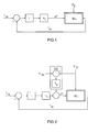
- FIG. 1 shows a fast analog controller for controlling the lamp current of a low-pressure discharge lamp according to the prior art.
- W / L designates a converter, in this case a half-bridge oscillator, with a connected low-pressure discharge lamp L.
- the signal line leading into block W / L is designated ⁇ T, which symbolizes that the switching times or the period duration of the converter operation are set here .
- I Li The outgoing from the block W / L signal line is denoted by I Li , which is symbolized that here the lamp current is measured by the lamp L.
- I Li shows that the measured "actual" lamp current I Li is compared via a comparator with a current setpoint I Ls .
- the setpoint deviation is fed to a fast analog integral control element designated I.
- the output signal of the integral control element I is multiplied by a certain factor k 1 and, as already mentioned, used to set the period T of the converter operation.
- the integral control I outputs a zero signal, the period remains the same. Therefore, the signal line to the block W / L is designated ⁇ T in terms of period change.
- FIG. 2 shows the invention in comparison to FIG. It will be for appropriate Parts using the same reference numerals. The following description focuses on the differences.
- the intermediate circuit voltage is here designated by the symbol U Zi .
- U Zs denotes a DC link voltage reference.
- the intermediate circuit voltage actual value (measured value) U Zi is compared via a comparator with the intermediate circuit voltage setpoint U Zs , multiplied by a constant k 2 and added to the already described with reference to Figure 1, multiplied by the constant k 1 output of the integral control I in the manner already described to influence the period of the converter operation.
- the constants k 1 and k 2 allow an adaptation of the behavior.
- the unit designated by the symbol SG from the comparator for comparing the intermediate circuit voltage actual value U Zi with the intermediate circuit voltage setpoint U Zs and the k 2 multiplication thus forms a disturbance variable connection to the control circuit, which otherwise corresponds in principle to FIG.
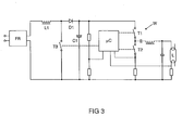
- the arrangement described in Figure 2 is part of a conventional electronic ballast for supplying a low-pressure discharge lamp L.
- a block diagram is shown in Figure 3.
- the intermediate circuit voltage U Zi is a conventional diode bridge rectifier with conventional filter elements to prevent the recovery of high frequency components in the network, in FIG 3 labeled FR generated.
- a power factor correction circuit is used, in this case a boost converter with the switching transistor T3, the inductance L1, the diode D1 and the storage capacitor C1 for the intermediate circuit voltage U Zi .
- the intermediate circuit voltage U Zi must be measured anyway, which is shown in Figure 3 by the tap on the unspecified voltage divider circuit. In this embodiment, this measurement is used simultaneously for the feedforward control illustrated in FIG.
- the feedforward control, the control loop, the control of the half-bridge oscillator W and the control of the boost converter are implemented together in software in a digital microcontroller .mu.C.
- the half-bridge oscillator W has the two switching transistors T1 and T2 of Figure 3 and supplies the lamp circuit connected in the usual way and not explained here with the lamp L at the center tap between the switching transistors T1 and T2 with a high-frequency oscillating supply voltage.
- the microcontroller .mu.C measures in the manner indicated in FIG. 3 the current through the lamp L and the current through the lower switching transistor T2 in order to correspondingly control the half-bridge oscillator W.
Abstract
Description
Die vorliegende Erfindung bezieht sich auf ein elektronisches Vorschaltgerät für Lampen, insbesondere aber nicht ausschließlich Niederdruckentladungslampen.The present invention relates to an electronic ballast for lamps, in particular but not exclusively low-pressure discharge lamps.
Üblicherweise enthalten solche Vorschaltgeräte einen Gleichrichter, der eine Versorgungswechselspannung gleichrichtet, um eine Zwischenkreisspannung zu erzeugen. Diese Zwischenkreisspannung liegt üblicherweise an einem Zwischenkreiskondensator zur Glättung bzw. Speicherung. Mit der Zwischenkreisspannung wird ein Wandler, beispielsweise ein Halbbrückenoszillator, versorgt, der seinerseits die Versorgungsleistung für die Lampe erzeugt, im Fall einer Niederdruckentladungslampe eine Hochfrequenzversorgungsleistung, im Fall einer Hochdruckentladungslampe aber auch eine in der Polarität mit vergleichsweise niedriger Frequenz alternierende Gleichspannung.Usually such ballasts contain a rectifier, the one AC supply voltage rectifies to a DC link voltage to create. This DC link voltage is usually at one DC link capacitor for smoothing or storage. With the DC link voltage becomes a converter, for example a half-bridge oscillator, supplied, which in turn generates the power supply for the lamp, in the case of a low pressure discharge lamp, a high frequency power supply, in the case of a high pressure discharge lamp but also in the polarity with a comparatively low frequency alternating DC voltage.
Es ist ferner bekannt, in solchen Vorschaltgeräten Regelschaltungen vorzusehen, mit denen der Lampenstrom oder die Lampenleistung auf einen konstanten Wert geregelt werden. Damit können Drifteffekte durch Lampenalterung, Temperaturänderungen u. Ä. kompensiert werden. It is also known to provide control circuits in such ballasts, with which the lamp current or the lamp power to a constant Value to be regulated. This can drift effects by lamp aging, Temperature changes u. Ä. be compensated.
Der vorliegenden Erfindung liegt das technische Problem zugrunde, eine verbessertes elektronisches Vorschaltgerät mit einer Regelschaltung anzugeben.The present invention is based on the technical problem, a to provide improved electronic ballast with a control circuit.
Die Erfindung bezieht sich auf ein elektronisches Vorschaltgerät für eine Lampe mit einem Gleichrichter zur Erzeugung einer gleichgerichteten Zwischenkreisspannung, einem Wandler zum Erzeugen einer Versorgungsleistung für die Lampe, einer Steuerung zur Zwangssteuerung des Wandlers und einer Regelschaltung zur Regelung des Lampenstromes oder der Lampenleistung, die dazu ausgelegt ist, die Steuerung des Wandlers zu beeinflussen, dadurch gekennzeichnet, dass das Vorschaltgerät dazu ausgelegt ist, dass die Steuerung des Wandlers auch durch eine Schwankungen der gleichgerichteten Zwischenkreisspannung berücksichtigende Störgrößenaufschaltung beeinflusst wird.The invention relates to an electronic ballast for a Lamp with a rectifier for generating a rectified intermediate circuit voltage, a converter for generating a power supply for the lamp, a controller for forced control of the converter and a control circuit for controlling the lamp current or the lamp power, which is designed to influence the control of the converter, characterized in that the ballast is designed to that the control of the converter also by a fluctuation of the rectified DC link voltage taking into account disturbance variable connection being affected.
Die Erfindung bezieht sich ferner auf ein entsprechendes Verfahren.The invention further relates to a corresponding method.
Bevorzugte Ausgestaltungen sind in den abhängigen Ansprüchen angegeben.Preferred embodiments are specified in the dependent claims.
Die Grundidee der Erfindung ist die Folgende: Bei der Gleichrichtung der Versorgungsleistung verbleibt prinzipiell eine Restmodulation der Zwischenkreisspannung. Diese Modulation beeinflusst den Wandler und damit den Betrieb der Lampe. Zwar lässt sich bei einer an sich bekannten Regelschaltung auch eine solche Modulation ausregeln, jedoch hat der Erfinder festgestellt, dass die Zwischenkreisspannungsmodulation im Vergleich zu anderen Störgrößen wie Lampenalterung, Temperaturänderungen und dgl. vergleichsweise schnell ist und vor allem in vielen Fällen die einzige in diesem Sinn schnelle Störgröße ist. Da das Modulationsverhalten der Zwischenkreisspannung bei einem bekannten Gleichrichter und einem gegebenen Zwischenkreiskondensator relativ konstant im Sinne von vorhersagbar oder berechenbar ist, schlägt die Erfindung vor, die Modulation der Zwischenkreisspannung als Störgröße im Rahmen einer Störgrößenaufschaltung außerhalb der eigentlichen Regelungsrückkopplung zu berücksichtigen. Daraus ergibt sich der Vorteil, dass die Regelschaltung auf einen deutlich langsameren Betrieb ausgelegt werden kann und auch die notwendigen Messungen, etwa die Lampenstrommessung, entsprechend langsam durchgeführt werden können. Der rückgekoppelte Regelkreis wird also weniger anspruchsvoll und die konventionellerweise für eine relativ schnelle Regelung ursächliche Störgröße "ausgegliedert" und separat über die Störgrößenaufschaltung berücksichtigt. Die Störgrößenaufschaltung bedeutet dabei eine "rechnerische" Berücksichtigung im Sinne einer - im Regelfall proportionalen - Berücksichtigung der Abweichung der Störgröße von einem Nennwert bei der Steuerung des Wandlers.The basic idea of the invention is the following: In the rectification of Supply power remains in principle a residual modulation of the DC link voltage. This modulation affects the converter and thus the Operation of the lamp. Although can be in a known control circuit also compensate for such a modulation, however, the inventor has found that the DC link voltage modulation compared to others Disturbances such as lamp aging, temperature changes and the like. Comparatively is fast and especially in many cases the only one in this Sense is fast disturbance. Since the modulation behavior of the DC link voltage in a known rectifier and a given DC link capacitor relatively constant in the sense of predictable or is calculable, the invention proposes the modulation of the DC link voltage as a disturbance variable in the context of a feedforward control outside to consider the actual feedback control. from that There is the advantage that the control circuit to a much slower Operation can be designed and also the necessary measurements, about the lamp current measurement, be carried out slowly accordingly can. The feedback loop becomes less demanding and conventionally causative for relatively fast control Disturbance "outsourced" and taken into account separately via the feedforward control. The disturbance variable connection means a "mathematical" Consideration in the sense of a - usually proportional - consideration the deviation of the disturbance variable from a nominal value in the control of the converter.
Vorzugsweise kann ein relativ langsamer I-Regler verwendet werden, der einfach zu realisieren ist und bei langsamen Regelungen gut arbeitet. Er hat überdies den Vorteil, keine bleibende Regelabweichung zuzulassen.Preferably, a relatively slow I-regulator can be used which easy to implement and works well with slow controls. He has Moreover, the advantage of not allowing a permanent deviation.
Ferner ist bevorzugt, die Regelschaltung digital auszuführen. Eine digitale Regelschaltung erfordert jedenfalls dann, wenn keine hohen Anforderungen an die Geschwindigkeit gestellt werden, einen begrenzten technischen Aufwand. Darüber hinaus eignet sie sich gut für eine im Rahmen der Erfindung bevorzugte Integration in eine ebenfalls digitale Steuerschaltung, die vorzugsweise durch einen Mikrocontroller, also einen programmierbaren IC, realisiert ist. Die Regelschaltung lässt sich dann also im Wesentlichen softwaretechnisch realisieren. In solchen Fällen, in denen also aus von der Regelung unabhängigen Gründen ohnehin eine digitale Schaltung, insbesondere ein Mikrocontroller, vorgesehen ist, ist der für die digitale Regelschaltung erforderliche Aufwand deutlich geringer als der für eine konventionelle analoge Regelschaltung. Auch hier kann der Aufwand bei geringen Geschwindigkeitsanforderungen deutlich reduziert werden.Furthermore, it is preferable to execute the control circuit digitally. A digital one In any case, control circuit requires, if no high demands be set to the speed, a limited technical effort. In addition, it is well suited for one within the scope of the invention preferred integration in a likewise digital control circuit, preferably realized by a microcontroller, so a programmable IC is. The control circuit can then be essentially software-related realize. In such cases, ie in which of the scheme independent reasons anyway a digital circuit, in particular a Microcontroller, is provided, which is required for the digital control circuit Effort significantly lower than that for a conventional analogue Control circuit. Again, the effort at low speed requirements be significantly reduced.
Das erfindungsgemäße Vorschaltgerät weist vorzugsweise eine sog. Leistungsfaktorkorrekturschaltung auf, also eine Schaltung, die für eine möglichst sinusförmige Leistungsaufnahme aus dem Wechselspannungsnetz sorgt. Damit können die pulsartigen Stromspitzen vermieden werden, die bei einer einfachen Aufladung des Zwischenkreiskondensators mit einem Gleichrichter dann entstehen, wenn die Netzspannung über die momentane Zwischenkreisspannung ansteigt. Ein bevorzugtes Beispiel für eine solche Leistungsfaktorkorrekturschaltung (auch als PFC-Schaltung bezeichnet) sind ein sog. Hochsetzer (Boost-Wandler) und ein sog. SEPIC-Wandler, die an sich bekannt sind.The ballast according to the invention preferably has a so-called power factor correction circuit on, so a circuit that for as possible sinusoidal power consumption from the AC mains provides. Thus, the pulse-like current peaks can be avoided, which at a simple charging of the DC link capacitor with a rectifier then arise when the mains voltage over the instantaneous DC link voltage increases. A preferred example of such a power factor correction circuit (also referred to as PFC circuit) are a so-called. Hochsetzer (boost converter) and a so-called. SEPIC converter, known per se are.
Zur Steuerung der Leistungsfaktorkorrekturschaltung ist ohnehin eine Messung der Zwischenkreisspannung erforderlich, so dass die Erfindung in solchen Fällen einen besonders geringen Zusatzaufwand erfordert. Vorzugsweise ist dabei die Steuerung der Leistungsfaktorkorrekturschaltung ebenfalls in der digitalen Steuerschaltung integriert.To control the power factor correction circuit is anyway a measurement the intermediate circuit voltage required, so that the invention in such Cases requires a particularly small additional effort. Preferably is the control of the power factor correction circuit also integrated in the digital control circuit.
Im Folgenden wird die Erfindung anhand eines schematischen Ausführungsbeispiels näher erläutert, wobei die Einzelmerkmale auch in anderen Kombinationen erfindungswesentlich sein können. Insbesondere wird noch einmal ausdrücklich festgestellt, dass die Erfindung sowohl einen Vorrichtungs- als auch einen Verfahrenscharakter hat und sich die vorstehende sowie die nachfolgende Beschreibung implizit auf beide Aspekte beziehen.
Figur 1- zeigt ein schematisches Blockschaltbild einer analogen Regelschaltung in einem konventionellen Vorschaltgerät.
- Figur 2
- zeigt im Vergleich zu
Figur 1 eine digitale Regelschaltung mit Störgrößenaufschaltung in einem erfindungsgemäßen Vorschaltgerät. - Figur 3
- zeigt ein schematisches Blockschaltbild eines erfindungsgemäßen elektronischen Vorschaltgeräts mit einer digitalen Regelschaltung nach Figur 2.
- FIG. 1
- shows a schematic block diagram of an analog control circuit in a conventional ballast.
- FIG. 2
- shows in comparison to Figure 1, a digital control circuit with feedforward control in a ballast according to the invention.
- FIG. 3
- shows a schematic block diagram of an electronic ballast according to the invention with a digital control circuit of Figure 2.
Figur 1 zeigt einen schnellen analogen Regler zur Regelung des Lampenstroms einer Niederdruckentladungslampe nach dem Stand der Technik. In Figur 1 bezeichnet W/L einen Wandler, hier einen Halbbrückenoszillator, mit einer angeschlossenen Niederdruckentladungslampe L. Die in den Block W/L hineinführende Signalleitung ist mit ΔT bezeichnet, womit symbolisiert ist, dass hier die Schaltzeiten bzw. die Periodendauer des Wandlerbetriebs eingestellt werden. Die aus dem Block W/L hinausführende Signalleitung ist mit ILi bezeichnet, womit symbolisiert ist, dass hier der Lampenstrom durch die Lampe L gemessen wird. Im linken Bereich der Figur 1 erkennt man, dass der gemessene "Ist"-Lampenstrom ILi über einen Komparator verglichen wird mit einem Stromsollwert ILs . Die Sollwertabweichung wird einem mit I bezeichneten schnellen analogen Integralregelglied zugeführt. Das Ausgangssignal des Integralregelgliedes I wird mit einem bestimmten Faktor k1 multipliziert und, wie bereits erwähnt, zur Einstellung der Periodendauer T des Wandlerbetriebs verwendet. Wenn das Integralregelglied I ein Nullsignal ausgibt, bleibt die Periodendauer gleich. Daher ist die Signalleitung zu dem Block W/L mit ΔT im Sinne einer Periodendaueränderung bezeichnet.Figure 1 shows a fast analog controller for controlling the lamp current of a low-pressure discharge lamp according to the prior art. In FIG. 1, W / L designates a converter, in this case a half-bridge oscillator, with a connected low-pressure discharge lamp L. The signal line leading into block W / L is designated ΔT, which symbolizes that the switching times or the period duration of the converter operation are set here , The outgoing from the block W / L signal line is denoted by I Li , which is symbolized that here the lamp current is measured by the lamp L. 1 shows that the measured "actual" lamp current I Li is compared via a comparator with a current setpoint I Ls . The setpoint deviation is fed to a fast analog integral control element designated I. The output signal of the integral control element I is multiplied by a certain factor k 1 and, as already mentioned, used to set the period T of the converter operation. When the integral control I outputs a zero signal, the period remains the same. Therefore, the signal line to the block W / L is designated ΔT in terms of period change.
Ein weiteres gemäß Figur 1 in den Block W/L eingehendes "Signal" ist die Zwischenkreisspannung UZ. Damit wird symbolisiert, dass der Wandlerbetrieb und der Lampenbetrieb, sowie insbesondere der Lampenstrom ILi von der Zwischenkreisspannung UZ abhängen und insbesondere deren Modulationen unterworfen sind. Der in Figur 1 dargestellte konventionelle Regelkreis muss also schnell genug sein, die Zwischenkreisspannungsmodulation mit einer typischen Frequenz von 100 Hz auszuregeln. Bei hochwertigen elektronischen Vorschaltgeräten darf die Modulation des Lampenstromes bzw. der Lampenleistung bestimmte Grenzen nicht überschreiten.Another in accordance with Figure 1 in the block W / L incoming "signal" is the intermediate circuit voltage U Z. This symbolizes that the converter operation and the lamp operation, and in particular the lamp current I Li depend on the intermediate circuit voltage U Z and in particular are subjected to their modulations. The conventional control circuit shown in Figure 1 must therefore be fast enough to control the DC link voltage modulation with a typical frequency of 100 Hz. For high-quality electronic ballasts, the modulation of the lamp current or the lamp power must not exceed certain limits.
Eine Alternative bzw. auch flankierende Maßnahme besteht darin, den Zwischenkreiskondensator ausreichend groß zu wählen, um die Zwischenkreisspannungsmodulation an sich klein zu halten. Ein großer Zwischenkreiskondensator ist jedoch mit zusätzlichen Kosten verbunden und erhöht überdies den Einschaltstrom des Vorschaltgeräts.An alternative or flanking measure is the DC link capacitor sufficiently large to select the DC link voltage modulation to keep small in itself. A large DC link capacitor However, it is associated with additional costs and increases moreover the inrush current of the ballast.
Figur 2 zeigt im Vergleich zu Figur 1 die Erfindung. Dabei werden für entsprechende Teile die gleichen Bezugszeichen verwendet. Die folgende Beschreibung konzentriert sich auf die Unterschiede.FIG. 2 shows the invention in comparison to FIG. It will be for appropriate Parts using the same reference numerals. The following description focuses on the differences.
Zunächst ist die Zwischenkreisspannung hier mit dem Symbol UZi bezeichnet. Im Unterschied dazu bezeichnet UZs einen Zwischenkreisspannungs-Sollwert. Der Zwischenkreisspannungs-Istwert (Messwert) UZi wird über einen Komparator mit dem Zwischenkreisspannungs-Sollwert UZs verglichen, mit einer Konstanten k2 multipliziert und mit dem bereits anhand Figur 1 beschriebenen, mit der Konstanten k1 multiplizierten Ausgang des Integralregelgliedes I addiert, um in der bereits beschriebenen Weise die Periodendauer des Wandlerbetriebs zu beeinflussen. Die Konstanten k1 und k2 erlauben eine Anpassung des Verhaltens.First, the intermediate circuit voltage is here designated by the symbol U Zi . In contrast, U Zs denotes a DC link voltage reference. The intermediate circuit voltage actual value (measured value) U Zi is compared via a comparator with the intermediate circuit voltage setpoint U Zs , multiplied by a constant k 2 and added to the already described with reference to Figure 1, multiplied by the constant k 1 output of the integral control I in the manner already described to influence the period of the converter operation. The constants k 1 and k 2 allow an adaptation of the behavior.
Die mit dem Symbol SG bezeichnete Einheit aus dem Komparator zum Vergleich des Zwischenkreisspannungs-Istwerts UZi mit dem Zwischenkreisspannungs-Sollwert UZs und der k2-Multiplikation bildet damit eine Störgrößenaufschaltung zu dem im Übrigen im Prinzip Figur 1 entsprechenden Regelkreis.The unit designated by the symbol SG from the comparator for comparing the intermediate circuit voltage actual value U Zi with the intermediate circuit voltage setpoint U Zs and the k 2 multiplication thus forms a disturbance variable connection to the control circuit, which otherwise corresponds in principle to FIG.
Allerdings kann mit der Störgrößenaufschaltung SG die Zwischenkreisspannungsmodulation ausreichend genau und vor allem ohne technischen Aufwand relativ schnell berücksichtigt werden. Daher muss bei dem Regelkreis nach Figur 2 keine schnelle Messung des Lampenstromes ILi erfolgen. Ferner kann das Integralregelglied I langsam sein. Der Regelkreis hat nämlich nunmehr nur die Aufgabe, zeitlich relativ langsam erfolgende Änderungen des Wandler- und Lampenbetriebs auszuregeln.However, the DC link voltage modulation can be taken into account relatively accurately and, above all, without any technical outlay relatively quickly with the disturbance variable connection SG. Therefore, in the control circuit of Figure 2 no rapid measurement of the lamp current I Li must be done. Furthermore, the integral control I can be slow. The control circuit now only has the task of correcting relatively slow changes in converter and lamp operation over time.
Die in Figur 2 beschriebene Anordnung ist Bestandteil eines im Übrigen konventionellen elektronischen Vorschaltgeräts zur Versorgung einer Niederdruckentladungslampe L. Ein Blockschaltbild dazu zeigt Figur 3. Die Zwischenkreisspannung UZi wird über einen konventionellen Diodenbrückengleichrichter mit üblichen Filterelementen zur Verhinderung der Rückspeisung von Hochfrequenzanteilen ins Netz, in Figur 3 mit FR bezeichnet, erzeugt. Dabei findet eine Leistungsfaktorkorrekturschaltung Anwendung, in diesem Fall ein Boost-Wandler mit dem Schalttransistor T3, der Induktivität L1, der Diode D1 und dem Speicherkondensator C1 für die Zwischenkreisspannung UZi. Zur Steuerung des Schalttransistors T3 des Boost-Wandlers muss die Zwischenkreisspannung UZi ohnehin gemessen werden, was in Figur 3 durch den Abgriff an der nicht näher bezeichneten Spannungsteilerschaltung dargestellt ist. Bei diesem Ausführungsbeispiel wird diese Messung gleichzeitig für die in Figur 2 dargestellte Störgrößenaufschaltung verwendet. Im Übrigen sind die Störgrößenaufschaltung, der Regelkreis, die Steuerung des Halbbrückenoszillators W und die Steuerung des Boost-Wandlers gemeinsam softwaretechnisch in einem digitalen Mikrocontroller µC realisiert. Der Halbbrückenoszillator W weist die beiden Schalttransistoren T1 und T2 aus Figur 3 auf und versorgt den in üblicher Weise beschalteten und hier nicht näher erläuterten Lampenkreis mit der Lampe L an dem Mittenabgriff zwischen den Schalttransistoren T1 und T2 mit einer hochfrequent oszillierenden Versorgungsspannung. Der Mikrocontroller µC misst in der in Figur 3 angedeuteten Weise den Strom durch die Lampe L und den Strom durch den unteren Schalttransistor T2, um den Halbbrückenoszillator W entsprechend anzusteuern.The arrangement described in Figure 2 is part of a conventional electronic ballast for supplying a low-pressure discharge lamp L. A block diagram is shown in Figure 3. The intermediate circuit voltage U Zi is a conventional diode bridge rectifier with conventional filter elements to prevent the recovery of high frequency components in the network, in FIG 3 labeled FR generated. In this case, a power factor correction circuit is used, in this case a boost converter with the switching transistor T3, the inductance L1, the diode D1 and the storage capacitor C1 for the intermediate circuit voltage U Zi . To control the switching transistor T3 of the boost converter, the intermediate circuit voltage U Zi must be measured anyway, which is shown in Figure 3 by the tap on the unspecified voltage divider circuit. In this embodiment, this measurement is used simultaneously for the feedforward control illustrated in FIG. Incidentally, the feedforward control, the control loop, the control of the half-bridge oscillator W and the control of the boost converter are implemented together in software in a digital microcontroller .mu.C. The half-bridge oscillator W has the two switching transistors T1 and T2 of Figure 3 and supplies the lamp circuit connected in the usual way and not explained here with the lamp L at the center tap between the switching transistors T1 and T2 with a high-frequency oscillating supply voltage. The microcontroller .mu.C measures in the manner indicated in FIG. 3 the current through the lamp L and the current through the lower switching transistor T2 in order to correspondingly control the half-bridge oscillator W.
Claims (8)
einem Gleichrichter zur Erzeugung einer gleichgerichteten Zwischenkreisspannung (UZ),
einem Wandler (W) zum Erzeugen einer Versorgungsleistung für die Lampe (L),
einer Steuerung zur Zwangssteuerung des Wandlers (W)
und einer Regelschaltung (I) zur Regelung des Lampenstromes (ILi) oder der Lampenleistung, die dazu ausgelegt ist, die Steuerung des Wandlers (W) zu beeinflussen,
dadurch gekennzeichnet, dass das Vorschaltgerät dazu ausgelegt ist, dass die Steuerung des Wandlers (W) auch durch eine Schwankungen der gleichgerichteten Zwischenkreisspannung (UZ) berücksichtigende Störgrößenaufschaltung (SG) beeinflusst wird.Electronic ballast for a lamp (L) with
a rectifier for generating a rectified intermediate circuit voltage (U Z ),
a converter (W) for generating a supply power for the lamp (L),
a controller for forced control of the converter (W)
and a control circuit (I) for controlling the lamp current (I Li ) or the lamp power, which is designed to influence the control of the converter (W),
characterized in that the ballast is designed so that the control of the converter (W) is also influenced by fluctuations in the rectified intermediate circuit voltage (U Z ) taking into account disturbance variable connection (SG).
eine Versorgungswechselspannung zu einer Zwischenkreisspannung (UZ) mit einem Gleichrichter gleichgerichtet wird,
mit der Zwischenkreisspannung (UZ) ein Wandler (W) versorgt wird,
mit dem Wandler (W) eine Versorgungsleistung für die Lampe (L) erzeugt wird,
mit einer Steuerung der Wandler (W) zwangsgesteuert wird,
mit einer Regelschaltung der Lampenstrom (ILi) oder die Lampenleistung geregelt und dabei die Steuerung des Wandlers (W) beeinflusst wird,
dadurch gekennzeichnet, dass die Steuerung des Wandlers (W) auch durch eine Schwankungen der gleichgerichteten Zwischenkreisspannung (UZ) berücksichtigende Störgrößenaufschaltung (SG) beeinflusst wird.Method for operating a lamp (L) with an electronic ballast according to one of the preceding claims, in which
an AC supply voltage to a DC link voltage (U Z ) is rectified with a rectifier,
with the intermediate circuit voltage (U Z ) a converter (W) is supplied,
with the converter (W) a supply power for the lamp (L) is generated,
with a control of the converter (W) is force-controlled,
controlled by a control circuit, the lamp current (I Li ) or the lamp power and thereby the control of the converter (W) is influenced,
characterized in that the control of the converter (W) is also influenced by a fluctuation of the rectified intermediate circuit voltage (U Z ) taking into account disturbance variable connection (SG).
Applications Claiming Priority (2)
| Application Number | Priority Date | Filing Date | Title |
|---|---|---|---|
| DE102004016945 | 2004-04-06 | ||
| DE102004016945A DE102004016945A1 (en) | 2004-04-06 | 2004-04-06 | Electronic ballast with control circuit and feedforward control |
Publications (1)
| Publication Number | Publication Date |
|---|---|
| EP1585373A1 true EP1585373A1 (en) | 2005-10-12 |
Family
ID=34895495
Family Applications (1)
| Application Number | Title | Priority Date | Filing Date |
|---|---|---|---|
| EP05004713A Withdrawn EP1585373A1 (en) | 2004-04-06 | 2005-03-03 | Electronic ballast with current control and positive feedback of a disturbance signal |
Country Status (4)
| Country | Link |
|---|---|
| US (1) | US20050218824A1 (en) |
| EP (1) | EP1585373A1 (en) |
| CA (1) | CA2503752A1 (en) |
| DE (1) | DE102004016945A1 (en) |
Families Citing this family (2)
| Publication number | Priority date | Publication date | Assignee | Title |
|---|---|---|---|---|
| CN101014221A (en) * | 2005-10-12 | 2007-08-08 | 国际整流器公司 | 8-pin pfc and ballast control ic |
| DE102010039430A1 (en) * | 2010-08-18 | 2012-02-23 | Osram Ag | Electronic ballast and method for operating at least one discharge lamp |
Citations (6)
| Publication number | Priority date | Publication date | Assignee | Title |
|---|---|---|---|---|
| DE4110225A1 (en) * | 1991-03-28 | 1992-10-01 | Abb Patent Gmbh | Control method for inverter with induction machine - varying torque generating demand value with ripple on DC intermediate circuit voltage |
| EP0596740A1 (en) * | 1992-11-05 | 1994-05-11 | General Electric Company | Feedback-controlled circuit and method for powering a high intensity discharge lamp |
| EP0605052A1 (en) * | 1992-12-28 | 1994-07-06 | Koninklijke Philips Electronics N.V. | Ballast for gas discharge lamps |
| US20020067139A1 (en) * | 2000-12-05 | 2002-06-06 | Philips Elctronics North America Corporation | Electronic ballast with feed-forward control |
| WO2002098187A1 (en) * | 2001-05-31 | 2002-12-05 | Koninklijke Philips Electronics N.V. | Power control device, apparatus and method of controlling the power supplied to a discharge lamp |
| US20030057881A1 (en) * | 2001-09-04 | 2003-03-27 | Koninklijke Philips Electronics N.V. | Adaptive control for half-bridge universal lamp drivers |
Family Cites Families (5)
| Publication number | Priority date | Publication date | Assignee | Title |
|---|---|---|---|---|
| US3890537A (en) * | 1974-01-02 | 1975-06-17 | Gen Electric | Solid state chopper ballast for gaseous discharge lamps |
| US4327309A (en) * | 1980-06-23 | 1982-04-27 | General Electric Company | Fluorescent lamp power supply with low voltage lamp polarity reversal |
| US5371440A (en) * | 1993-12-28 | 1994-12-06 | Philips Electronics North America Corp. | High frequency miniature electronic ballast with low RFI |
| DE10051139A1 (en) * | 2000-10-16 | 2002-04-25 | Tridonic Bauelemente | Electronic voltage adapter has full bridge circuit with both diagonals having regulated constant current source for regulating the gas discharge lamp current |
| DE10106438A1 (en) * | 2001-02-09 | 2002-08-14 | Patent Treuhand Ges Fuer Elektrische Gluehlampen Mbh | Ballast for operating electric lamps |
-
2004
- 2004-04-06 DE DE102004016945A patent/DE102004016945A1/en not_active Withdrawn
-
2005
- 2005-03-03 EP EP05004713A patent/EP1585373A1/en not_active Withdrawn
- 2005-04-04 CA CA002503752A patent/CA2503752A1/en not_active Abandoned
- 2005-04-06 US US11/099,513 patent/US20050218824A1/en not_active Abandoned
Patent Citations (6)
| Publication number | Priority date | Publication date | Assignee | Title |
|---|---|---|---|---|
| DE4110225A1 (en) * | 1991-03-28 | 1992-10-01 | Abb Patent Gmbh | Control method for inverter with induction machine - varying torque generating demand value with ripple on DC intermediate circuit voltage |
| EP0596740A1 (en) * | 1992-11-05 | 1994-05-11 | General Electric Company | Feedback-controlled circuit and method for powering a high intensity discharge lamp |
| EP0605052A1 (en) * | 1992-12-28 | 1994-07-06 | Koninklijke Philips Electronics N.V. | Ballast for gas discharge lamps |
| US20020067139A1 (en) * | 2000-12-05 | 2002-06-06 | Philips Elctronics North America Corporation | Electronic ballast with feed-forward control |
| WO2002098187A1 (en) * | 2001-05-31 | 2002-12-05 | Koninklijke Philips Electronics N.V. | Power control device, apparatus and method of controlling the power supplied to a discharge lamp |
| US20030057881A1 (en) * | 2001-09-04 | 2003-03-27 | Koninklijke Philips Electronics N.V. | Adaptive control for half-bridge universal lamp drivers |
Also Published As
| Publication number | Publication date |
|---|---|
| US20050218824A1 (en) | 2005-10-06 |
| CA2503752A1 (en) | 2005-10-06 |
| DE102004016945A1 (en) | 2005-10-27 |
Similar Documents
| Publication | Publication Date | Title |
|---|---|---|
| DE102004033354B4 (en) | Method for controlling a switch in a boost converter and drive circuit | |
| EP1872627B1 (en) | Parameterizable digital pfc (power factor correlation) | |
| DE602005000241T2 (en) | Control system for a ballast self-oscillating inverter | |
| EP2188886B1 (en) | Method for regulating a dc-to-dc converter | |
| DE102018113402B4 (en) | METHOD OF OPERATING A POWER SUPPLY WITH A LOW POWER STANDBY, POWER SUPPLY AND CONTROLLER | |
| DE102013106425B4 (en) | Switching power supply device and use of such | |
| EP2604097B1 (en) | Modulation of a pfc during dc operation | |
| EP1227705A2 (en) | Ballast with SEPIC converter for lamps | |
| DE19708791A1 (en) | Control circuit and electronic ballast with such a control circuit | |
| EP1696713B1 (en) | Electronic ballast with current measuring means for high-pressure discharge lamps | |
| EP1737279A2 (en) | Device and method for providing a sinusoidally amplitude modulated operating voltage | |
| EP1585373A1 (en) | Electronic ballast with current control and positive feedback of a disturbance signal | |
| DE2217023C3 (en) | Feed circuit for a direct current consumer fed by a single or multi-phase alternating current source | |
| DE10120497B4 (en) | Electronic ballast | |
| DE102016107578B4 (en) | Operating circuit and method for operating at least one light source | |
| EP0125385B1 (en) | Arrangement for generating regulated and/or adjustable dc voltages or dc currents | |
| DE19522369A1 (en) | Rectifier-power pack e.g. for welding or plasma-cutting apparatus | |
| DE10045709A1 (en) | Electronic ballast | |
| EP3552458B1 (en) | Circuit assembly and method for operating a lighting means | |
| EP2474206B1 (en) | Active factor correction in current- or power-controlled operating devices for lighting devices | |
| DE4140748C1 (en) | Converter supplying load in form of parallel oscillating circuit - has correction component assigned to regulating circuit for extinguishing time, also producing actual value for comparison with stipulated value | |
| DE10205552A1 (en) | Circuit for energy optimized brightness control of gas discharge lamps, has power compensator rectifier and inverter | |
| AT17206U1 (en) | Supply circuit and method for supplying an electrical load | |
| EP1142665A2 (en) | Arc welding machine | |
| DE2030152A1 (en) | Circuit for generating a stabilized DC voltage by means of phase control with thyristor |
Legal Events
| Date | Code | Title | Description |
|---|---|---|---|
| PUAI | Public reference made under article 153(3) epc to a published international application that has entered the european phase |
Free format text: ORIGINAL CODE: 0009012 |
|
| AK | Designated contracting states |
Kind code of ref document: A1 Designated state(s): AT BE BG CH CY CZ DE DK EE ES FI FR GB GR HU IE IS IT LI LT LU MC NL PL PT RO SE SI SK TR |
|
| AX | Request for extension of the european patent |
Extension state: AL BA HR LV MK YU |
|
| 17P | Request for examination filed |
Effective date: 20051010 |
|
| AKX | Designation fees paid |
Designated state(s): AT BE BG CH CY CZ DE DK EE ES FI FR GB GR HU IE IS IT LI LT LU MC NL PL PT RO SE SI SK TR |
|
| STAA | Information on the status of an ep patent application or granted ep patent |
Free format text: STATUS: THE APPLICATION IS DEEMED TO BE WITHDRAWN |
|
| 18D | Application deemed to be withdrawn |
Effective date: 20060724 |