EP1569324A1 - Drive apparatus, control method and program storage medium for the drive apparatus, and power output apparatus - Google Patents
Drive apparatus, control method and program storage medium for the drive apparatus, and power output apparatus Download PDFInfo
- Publication number
- EP1569324A1 EP1569324A1 EP05011717A EP05011717A EP1569324A1 EP 1569324 A1 EP1569324 A1 EP 1569324A1 EP 05011717 A EP05011717 A EP 05011717A EP 05011717 A EP05011717 A EP 05011717A EP 1569324 A1 EP1569324 A1 EP 1569324A1
- Authority
- EP
- European Patent Office
- Prior art keywords
- motor
- switching
- power
- switching element
- converter
- Prior art date
- Legal status (The legal status is an assumption and is not a legal conclusion. Google has not performed a legal analysis and makes no representation as to the accuracy of the status listed.)
- Granted
Links
Images


Classifications
-
- H—ELECTRICITY
- H02—GENERATION; CONVERSION OR DISTRIBUTION OF ELECTRIC POWER
- H02P—CONTROL OR REGULATION OF ELECTRIC MOTORS, ELECTRIC GENERATORS OR DYNAMO-ELECTRIC CONVERTERS; CONTROLLING TRANSFORMERS, REACTORS OR CHOKE COILS
- H02P6/00—Arrangements for controlling synchronous motors or other dynamo-electric motors using electronic commutation dependent on the rotor position; Electronic commutators therefor
- H02P6/08—Arrangements for controlling the speed or torque of a single motor
- H02P6/085—Arrangements for controlling the speed or torque of a single motor in a bridge configuration
-
- H—ELECTRICITY
- H02—GENERATION; CONVERSION OR DISTRIBUTION OF ELECTRIC POWER
- H02J—CIRCUIT ARRANGEMENTS OR SYSTEMS FOR SUPPLYING OR DISTRIBUTING ELECTRIC POWER; SYSTEMS FOR STORING ELECTRIC ENERGY
- H02J7/00—Circuit arrangements for charging or depolarising batteries or for supplying loads from batteries
- H02J7/14—Circuit arrangements for charging or depolarising batteries or for supplying loads from batteries for charging batteries from dynamo-electric generators driven at varying speed, e.g. on vehicle
- H02J7/1438—Circuit arrangements for charging or depolarising batteries or for supplying loads from batteries for charging batteries from dynamo-electric generators driven at varying speed, e.g. on vehicle in combination with power supplies for loads other than batteries
-
- H—ELECTRICITY
- H02—GENERATION; CONVERSION OR DISTRIBUTION OF ELECTRIC POWER
- H02J—CIRCUIT ARRANGEMENTS OR SYSTEMS FOR SUPPLYING OR DISTRIBUTING ELECTRIC POWER; SYSTEMS FOR STORING ELECTRIC ENERGY
- H02J7/00—Circuit arrangements for charging or depolarising batteries or for supplying loads from batteries
- H02J7/14—Circuit arrangements for charging or depolarising batteries or for supplying loads from batteries for charging batteries from dynamo-electric generators driven at varying speed, e.g. on vehicle
- H02J7/16—Regulation of the charging current or voltage by variation of field
- H02J7/24—Regulation of the charging current or voltage by variation of field using discharge tubes or semiconductor devices
-
- H—ELECTRICITY
- H02—GENERATION; CONVERSION OR DISTRIBUTION OF ELECTRIC POWER
- H02P—CONTROL OR REGULATION OF ELECTRIC MOTORS, ELECTRIC GENERATORS OR DYNAMO-ELECTRIC CONVERTERS; CONTROLLING TRANSFORMERS, REACTORS OR CHOKE COILS
- H02P27/00—Arrangements or methods for the control of AC motors characterised by the kind of supply voltage
- H02P27/04—Arrangements or methods for the control of AC motors characterised by the kind of supply voltage using variable-frequency supply voltage, e.g. inverter or converter supply voltage
- H02P27/048—Arrangements or methods for the control of AC motors characterised by the kind of supply voltage using variable-frequency supply voltage, e.g. inverter or converter supply voltage using AC supply for only the rotor circuit or only the stator circuit
-
- H—ELECTRICITY
- H02—GENERATION; CONVERSION OR DISTRIBUTION OF ELECTRIC POWER
- H02P—CONTROL OR REGULATION OF ELECTRIC MOTORS, ELECTRIC GENERATORS OR DYNAMO-ELECTRIC CONVERTERS; CONTROLLING TRANSFORMERS, REACTORS OR CHOKE COILS
- H02P27/00—Arrangements or methods for the control of AC motors characterised by the kind of supply voltage
- H02P27/04—Arrangements or methods for the control of AC motors characterised by the kind of supply voltage using variable-frequency supply voltage, e.g. inverter or converter supply voltage
- H02P27/06—Arrangements or methods for the control of AC motors characterised by the kind of supply voltage using variable-frequency supply voltage, e.g. inverter or converter supply voltage using dc to ac converters or inverters
- H02P27/08—Arrangements or methods for the control of AC motors characterised by the kind of supply voltage using variable-frequency supply voltage, e.g. inverter or converter supply voltage using dc to ac converters or inverters with pulse width modulation
-
- H—ELECTRICITY
- H02—GENERATION; CONVERSION OR DISTRIBUTION OF ELECTRIC POWER
- H02J—CIRCUIT ARRANGEMENTS OR SYSTEMS FOR SUPPLYING OR DISTRIBUTING ELECTRIC POWER; SYSTEMS FOR STORING ELECTRIC ENERGY
- H02J7/00—Circuit arrangements for charging or depolarising batteries or for supplying loads from batteries
- H02J7/34—Parallel operation in networks using both storage and other dc sources, e.g. providing buffering
- H02J7/345—Parallel operation in networks using both storage and other dc sources, e.g. providing buffering using capacitors as storage or buffering devices
Definitions
- the present invention relates to a drive apparatus, a control method for the drive apparatus, a storage medium in which is stored a program controlling the drive apparatus, and a power output apparatus.
- an apparatus for this type of power output apparatus comprising a capacitor that is connected to a positive bus line and a negative bus line of an inverter circuit for applying a three-phase alternating current to a motor, and a DC/DC converter capable of performing DC/DC conversion on the power from the DC power source and supplying to the capacitor.
- a charge is stored into the capacitor by using a reactor for temporarily storing the current of the DC power source as energy and stepping up the voltage of the DC power source, and the motor is driven with this charged capacitor as a DC power source.
- the voltage step-up operation by the DC/DC converter is fixed at a switching frequency (carrier frequency) where the efficiency is considered suitable at a given operating point, and is performed by controlling the switching at this fixed switching frequency.
- the drive apparatus and the power output apparatus of the present invention employ the following means to achieve at least one of the above-mentioned objects.
- the drive apparatus of the present invention comprises:
- the controller set the switching frequency for the switching element of the DC/DC converter on the basis of loss characteristics of the DC/DC converter corresponding to current flowing through the energy storing device, and by using the set switching frequency, control the switching of the switching element.
- the switching frequency where the loss of the DC/DC converter is smaller in accordance with the current flowing through the energy storing device, the DC/DC converter can be driven more efficiently. As a result, the energy efficiency of the overall apparatus can be further improved.
- the loss characteristics given here refer to the relationship between the switching frequency and the loss.
- the loss characteristics of the DC/DC converter may be obtained from the loss characteristics of the energy storing device and the loss characteristics of the switching element.
- the drive apparatus of the present invention may comprise a current calculator for calculating the current flowing through the energy storing device on the basis of the output required by the load and the voltage of the power source, or may comprise a current detector for directly detecting the current flowing through the energy storing device.
- a control method for the drive apparatus of the present invention is a control method for a drive apparatus comprising a DC/DC converter having an energy storing device capable of storing DC current as energy, and being capable, by using the energy storing device, of performing DC/DC conversion on an input DC voltage by the switching of a switching element and outputting to a load, and a power source capable of supplying DC power to the DC/DC converter, comprising the steps of:
- the switching frequency for the switching element of the DC/DC converter is set using the loss characteristics of the DC/DC converter corresponding to current flowing through the energy storing device, and switching control is performed on the switching element at the set switching frequency.
- the storage medium of the present invention for storing a program controlling the operation of a drive apparatus comprising a DC/DC converter having an energy storing device capable of storing DC current as energy, and being capable, by using the energy storing device, of performing DC/DC conversion on an input DC voltage by the switching of a switching element and outputting to a load, and a power source capable of supplying DC power to the DC/DC converter; is a computer readable storage medium in which is stored a program for executing by a computer:
- the computer can function as the controller to set the switching frequency for the switching element of the DC/DC converter by using the loss characteristics of the DC/DC converter corresponding to current flowing through the energy storing device, and to control the switching of the switching element at the set switching frequency. Therefore, by setting the switching frequency where the loss of the DC/DC converter is smaller in accordance with the current through the energy storing device, the DC/DC converter can be driven more efficiently. As a result, the energy efficiency of the overall drive apparatus can be further improved.
- a first power output apparatus of the present invention comprises:
- the controller set the switching frequency for the switching element of the inverter circuit using the loss characteristics of the power converter corresponding to current flowing through a neutral point of the motor, and at this set switching frequency, and control the switching of the switching element.
- a second power output apparatus of the present invention comprises:
- the loss characteristics of the power converter may also be obtained using the loss characteristics of the phase coils of the motor and the loss characteristics of the switching element.
- the first or second power output apparatus of the present invention may comprise a current calculator for calculating the current flowing through the neutral point of the motor on the basis of the output required by the power output apparatus and the voltage of the second power source, or may comprise a current detector for directly detecting the current flowing through the neutral point of the motor.
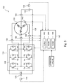
- Fig. 1 shows an overall configuration of the power output apparatus 20, which is the preferred first embodiment of the present invention.
- the power output apparatus 20 of this embodiment comprises a motor 22 that is rotationally driven by a three-phase alternating current, an inverter circuit 24 capable of converting DC power into three-phase AC power and supplying it to the motor 22, a capacitor 30 that is connected to a positive bus line 26 and a negative bus line 28 of the inverter circuit 24, a battery 32 capable of being charged and discharged, a DC/DC converter 34 capable of performing DC/DC conversion on the DC voltage from the battery 32 and supplying it to the capacitor 30, and an electronic control unit 40 for setting a switching frequency (carrier frequency) for the DC/DC converter 34 and controlling the overall apparatus.
- a switching frequency carrier frequency
- the motor 22 is, for example, configured as a synchronous generator-motor that is capable of electric power generation from a rotor, to which is attached a permanent magnetic on its outer surface, and a stator wound with three-phase coils.
- the rotary shaft of the motor 22 is the output shaft of the power output apparatus 20 of this embodiment and power is output from this rotary shaft.
- the motor 22 of this embodiment is configured as a generator-motor, electric power generation by the motor 22 is possible if power is input by the rotary shaft of the motor 22. It should be noted that if the power output apparatus 20 of this embodiment is mounted on a vehicle, the rotary shaft of the motor 22 will be connected directly or indirectly to an axle of the vehicle.
- the inverter circuit 24 is configured from six transistors T1 to T6 and six diodes D1 to D6.
- the six transistors T1 to T6 are arranged as pairs of transistors on the source side and sink side respectively with respect to the positive bus line 26 and the negative bus line 28, and to each connection point between the source side and the sink side is connected the respective three-phase coils (uvw) of the motor 22. Therefore, by controlling the proportion of the ON time of the paired transistors, T1 to T6, in a state where a potential difference acts between the positive bus line 26 and the negative bus line 28, a rotating magnetic field is formed by the three-phase coils of the motor 22 so as to enable the rotational drive of the motor 22.
- the battery 32 is configured, for example, as a nickel-hydride based or lithium-ion based secondary cell.
- the battery 32 is formed, for example, with a capacity larger than the capacity of the capacitor 30 at the same voltage.
- the DC/DC converter 34 comprises two transistors T7 and T8 arranged at the respective source side and sink side with respect to the positive bus line 26 and the negative bus line 28 of the inverter circuit 24, two diodes D7 and D8 arranged in an inverse-parallel connection with the respective transistors T7 and T8, and a reactor L that is connected to a common connection point of transistors T7 and T8.
- the electronic control unit 40 is configured as a microprocessor centering on a CPU 42, and comprises a ROM 44 in which is stored a processing program, a RAM 46 for temporarily storing data, and an input/output port (not shown).
- the electronic control unit 40 inputs, via an input port, a voltage Vb from a voltage sensor 50 for detecting the terminal voltage of the battery 32 and a reactor current I1 from a current sensor 52 for detecting the current flowing through the reactor L, a voltage Vc from a voltage sensor 54 for detecting the terminal voltage of the capacitor 30, phase currents Iu, Iv, and Iw from current sensors 56 to 60 for detecting the current flowing through each phase of the three-phase coils of the motor 22, a motor angle of revolution ⁇ from a revolution angle sensor 62 attached to the rotary shaft of the motor 22, a command value relating to the operation of the motor 22, and so forth.
- the electronic control unit 40 outputs, via an output port, control signals for performing switching control of the transistors T1 to T6 of the inverter circuit 24, control signals for performing switching control of transistors T7 and T8 of the DC/DC converter 34, and so forth.
- FIG. 2 is a flowchart showing an example of a DC/DC converter control routine that is executed by the electronic control unit 40 of the power output apparatus 20 of this embodiment. This routine is repeatedly executed at a predetermined interval (such as every 20 ms).
- the CPU 42 of the electronic control unit 40 first reads (step S 100) the torque command T* as the torque to be output by the motor 22, the motor angle of revolution ⁇ from the revolution angle sensor 62, and the voltage Vb of the battery 32 from the voltage sensor 50, then calculates (step S102) the output required BP* of the battery 32, which is the electric power necessary when driving the motor 22, on the basis of the torque command T* for the motor 22 that is read and the rpm N of the motor 22 that is calculated on the basis of the motor angle of revolution ⁇ .
- the output required BP* of the battery 32 is calculated as an electric power by converting a drive power from the motor 22.
- the power output apparatus 20 includes another accessory that is driven using electric power (output from DC/DC converter 34) from the battery 32, the power necessary to drive the accessory is added to the power that is calculated by converting the drive power from the motor 22.
- a known rpm sensor may be provided to directly detect the rpm N.
- the target reactor current I1* to be applied to the reactor L of the DC/DC converter 34 is calculated (step S104) by dividing the calculated output required BP* by the terminal voltage Vb of the battery 32, an optimum carrier frequency F, which is a carrier frequency that is optimum for efficiently switching the transistors T7 and T8 of the DC/DC converter 34, is set (step S106) from the calculated target reactor current I1*, and the DC/DC converter 34 is controlled (step S108) using the optimum carrier frequency F so that the target reactor current I1* flows to the reactor L, thereby terminating the routine.
- the setting of the optimum carrier frequency F will be described here.
- Fig. 3 shows the relationship between the carrier frequency and the loss of the reactor L (solid lines), and the relationship between the carrier frequency and the loss (switching loss) of transistors T7 and T8 (broken lines), when a current flowing through the reactor L is changed.
- the loss of the reactor L increases as the current flowing through the reactor L increases or as the carrier frequency lowers.
- the loss of transistors T7 and T8 increases as the current flowing through the reactor L increases or as the carrier frequency rises.
- the loss of the DC/DC converter 34 is now considered as a sum of the loss of the reactor L and the loss of transistors T7 and T8, the loss characteristics of the DC/DC converter 34 depended on the current flowing through the reactor L have the characteristics shown by the broken lines in Fig. 4. Therefore, by setting the carrier frequency where the loss of the DC/DC converter 34 is minimized on the basis of the current flowing through the reactor L, the DC/DC converter 34 can be efficiently driven.
- the relationship of the target reactor current I1* and the optimum carrier frequency F is obtained in advance, such as by experimentation, and stored into the ROM 44, and when the target reactor current I1* is obtained, the corresponding optimum carrier frequency F is derived from a map.
- the solid line in Fig. 4 represents the map showing the relationship between the target reactor current I1* and the optimum carrier frequency F.
- the command currents Iu*, Iv*, and Iw* to be supplied to the respective phase of the three-phase coils of the motor 22 are calculated from the torque command T* for the motor 22.
- the command voltages Vu*, Vv*, and Vw* for the respective phases of the motor 22 are calculated on the basis of the command currents Iu*, Iv*, and Iw*, and the respective phase currents Iu, Iv, and Iw, which are detected by the current sensors 56 to 60.
- a PWM signal is generated on the basis of the command voltages Vu*, Vv*, and Vw*, and the voltage Vc of the capacitor 30, which is detected by the voltage sensor 54, and the PWM signal is output to the inverter circuit 24.
- the target reactor current I1* flowing through the reactor L is calculated on the basis of the power (power requirement) required by the motor 22 and the terminal voltage Vb of the battery 32, and the optimum carrier frequency F is set where the loss of the DC/DC converter 34 is minimized on the basis of the target reactor current I1*.
- the optimum carrier frequency F is set where the loss of the DC/DC converter 34 is minimized on the basis of the target reactor current I1*.
- the target reactor current I1* is calculated on the basis of the power required by the motor 22 and the voltage Vb of the battery 32, and the optimum carrier frequency F is set from the calculated target reactor current I1*.
- the current flowing through the reactor L may be detected directly by the DC current sensor 52 and the optimum carrier frequency F may also be set from the detected current.
- the optimum carrier frequency F is set where the loss of the DC/DC converter 34 (loss of the reactor L and transistors T7 and T8) is minimized.
- the carrier frequency may be set within an allowable range centering on the optimum carrier frequency F.
- the power output apparatus 20 of this embodiment is applied to the case where the motor 22 is driven using the battery 32 as the power source. However, it may also be applied to a case where a general load that consumes power is driven.
- FIG. 5 shows the overall configuration of the power output apparatus 120 of the second embodiment.
- the power output apparatus 120 of the second embodiment comprises a motor 122 that is rotationally driven by a three-phase alternating current, an inverter circuit 124 capable of converting DC power to three-phase AC power and supplying it to the motor 122, a capacitor 130 that is connected to a positive bus line 126 and a negative bus line 128 of the inverter circuit 124, a DC power source 132 that is connected to a neutral point of the motor 122 and to the negative bus line 128 of the inverter circuit 124, and an electronic control unit 140 for controlling the overall apparatus.
- the power output apparatus 120 of the second embodiment has a similar configuration to the power output apparatus 20 of the first embodiment, except that the inverter circuit 124 operates the same function, by switching the transistors T1 to T6 of with each phase coil of the motor 22 functioning as a reactor, as the step-up/down operation of the DC/DC converter 34 in the power output apparatus 20 of the first embodiment. Therefore, with respect to the elements that correspond to the power output apparatus 20 of the first embodiment, a "100" is added to their reference numerals and their detailed descriptions will not be repeated.
- Fig. 6 is a circuit diagram of the power output apparatus 120 of the second embodiment focusing on phase u of the three-phase coils of the motor 122.
- phase u of the three-phase coils functioning as the reactor is stored into the capacitor 130 by the circuit shown by the solid lines in the figure.
- the voltage at this time can be set higher than the supply voltage of the battery 132.
- the battery 132 can be charged by the potential of the capacitor 130 using this circuit. Therefore, this circuit can be considered to be a step-up/down chopper circuit that is capable of stepping up the energy of the battery 132 and stores it into the capacitor 130, and charging the battery 132 by the potential of the capacitor 130.
- phases v and w of the three-phase coils of the motor 122 can also be considered to be step-up/down chopper circuits.
- the capacitor 130 can be charged by turning ON and OFF the transistors T2, T4, and T6, or the battery 132 can be charged by the charge stored in the capacitor 130.
- the potential difference caused by charging the capacitor 130 fluctuates according to the amount of charge that is stored in the capacitor 130, namely, the current flowing through the reactor, so that the terminal voltage of the capacitor 130 can be adjusted by controlling the switching of the transistors T2, T4, and T6 of the inverter circuit 124 to adjust the current flowing through the reactor.
- a pseudo-three-phase alternating current may be supplied to the three-phase coils of the motor 122 by controlling the switching of the transistors T1 to T6 of the inverter circuit 124.
- the motor 122 can be rotationally driven by the AC component and the DC component can be stored into the capacitor 130. Therefore, by controlling the switching of the transistors T1 to T6 of the inverter circuit 124, the motor 122 can be driven while the terminal voltage of the capacitor 130 is adjusted.
- the terminal voltage of the capacitor 130 is adjusted, for example, so that it is approximately double the terminal voltage of the battery 132.
- the circuit formed from the phase coils of the motor 122 and the transistors T1 to T6 and the diodes D1 to D6 of the inverter circuit 124 can be considered to be a step-up/down chopper circuit, which corresponds similarly to the DC/DC converter 34 of the power output apparatus 20 of the first embodiment. Therefore, if the optimum carrier frequency F is set where the loss based on the step-up/down operation of this circuit is minimized, the energy efficiency of the power output apparatus 120 of the second embodiment can be further improved.
- the setting of the optimum carrier frequency F can be performed as follows. First, the target neutral point current Io* flowing through the neutral point of the motor 122 is calculated.
- the target neutral point current Io* is calculated by dividing the output required BP*, calculated as an electric power by converting a drive power from the motor 122, (if another accessory that consumes electric power from the battery 132 exists, the power required by that accessory is added) by the voltage Vb of the battery 132.
- the optimum carrier frequency F is derived using the loss characteristics similar to those shown by the solid line of Fig. 4.
- the current flowing to the neutral point of the motor 122 may be directly detected by a current sensor 164, and the optimum carrier frequency F may be calculated using the detected current.
- the target neutral point current Io* flowing through the neutral point of the motor 122 is calculated on the basis of the power required by the motor 122 (battery required power BP*) and the terminal voltage Vb of the battery 132.
- the optimum switching frequency F is set where the loss of the circuit part functioning as the step-up/down chopper circuit is minimized.
- the capacitor 130 is attached so as to connect to the positive bus line 126 and to the negative bus line 128 of the inverter circuit 124.
- a capacitor 130B may be attached so as to connect to the positive bus line 126 of the inverter circuit 124 and to the neutral point of the motor 122 as shown in a power output apparatus 120B of the modified embodiment of Fig. 7.
- a DC power source for a voltage being the sum of the terminal voltage from the capacitor 130B and the terminal voltage from the battery 132 is attached so as to connect to the positive bus line 126 and to the negative bus line 128 of the inverter circuit 124.
- This configuration can be considered to be similar to the configuration of the power output apparatus 120 of the second embodiment where the capacitor 130 is attached so as to connect to the positive bus line 126 and to the negative bus line 128 of the inverter circuit 124.
- Fig. 8 is a circuit diagram of the power output apparatus 120B of the modification embodiment focusing on phase u of the three-phase coils of the motor 122.
- a short circuit shown by the broken lines in the figure is formed so that phase u of the three-phase coils of the motor 122 functions as a reactor.
- the transistor T2 is turned OFF from this state, the energy stored in phase u of the three-phase coils functioning as the reactor is stored into the capacitor 130B by the circuit shown by the solid lines in the figure.
- the battery 132 can be likewise charged by the charge of the capacitor 130B.
- this circuit stores the energy of the battery 132 into the capacitor 130B, and can be considered to be a chopper circuit that is capable of charging the battery 132 by the potential of the capacitor 130B. Similar to phase u, phases v and w of the motor 122 can also be considered to be chopper circuits. Thus, by turning ON and OFF the transistors T1 to T6, the capacitor 130B can be charged and the battery 132 can be charged by the charge stored in the capacitor 130B.
- the potential difference caused by charging the capacitor 130B fluctuates according to the amount of charge that is stored in the capacitor 130B, namely, the current flowing through the reactor, so that the terminal voltage of the capacitor 130B can be adjusted by controlling the switching of the transistors T1 to T6 of the inverter circuit 124 to adjust the current flowing through the reactor.
- a pseudo-three-phase alternating current may be supplied to the three-phase coils of the motor 122 by controlling the switching of the transistors T1 to T6 of the inverter circuit 124.
- the motor 122 can be rotationally driven by the AC component and the DC component can be stored into the capacitor 130B. Therefore, by controlling the switching of the transistors T1 to T6 of the inverter circuit 124, the motor 122 can be driven while the terminal voltage of the capacitor 130B is adjusted.
- the terminal voltage of the capacitor 130B is adjusted, for example, so that it is substantially the same as the terminal voltage of the battery 132.
- an effect similar to that of the power output apparatus 120 of the second embodiment can be achieved by setting the optimum carrier frequency F where the loss of the chopper circuit part is minimized from the current flowing to the neutral point as in the power output apparatus 120 of the second embodiment.
- the battery 132 is attached so as to connect to the negative bus line 128 of the inverter circuit 124 and to the neutral point of the motor 122.
- the battery 132 may be attached so as to connect to the positive bus line 126 of the inverter circuit 124 and to the neutral point of the motor 122.
- the battery 132 is attached so as to connect to the negative bus line 128 of the inverter circuit 124 and to the neutral point of the motor 122
- the capacitor 130B is attached so as to connect to the positive bus line 126 of the inverter circuit 124 and to the neutral point of the motor 122.
- the capacitor may be attached so as to connect to the negative bus line 128 of the inverter circuit 124 and to the neutral point of the motor 122
- the battery may be attached so as to connect to the positive bus line 126 of the inverter circuit 124 and to the neutral point of the motor 122.
- the target neutral point current Io* is calculated on the basis of the power required by the motor 122 (battery output required BP*) and the voltage Vb of the battery 132, and the optimum carrier frequency F is set from the calculated target neutral point current Io*.
- the current flowing through the neutral point of the motor 122 may be detected by the DC current sensor 164, and the optimum carrier frequency F may be set from the detected current.
- the optimum carrier frequency F is set where the loss of the chopper circuit part (phase coils and transistors T1 to T6) is minimized.
- the carrier frequency may be set within an allowable range centering on the optimum carrier frequency F.
- the synchronous generator-motor driven by the three-phase alternating current is used as the motors 22, 122.
- any type of motor driven by polyphase alternating current may be used.
Abstract
Description
- The present invention relates to a drive apparatus, a control method for the drive apparatus, a storage medium in which is stored a program controlling the drive apparatus, and a power output apparatus.
- Heretofore, an apparatus has been proposed for this type of power output apparatus comprising a capacitor that is connected to a positive bus line and a negative bus line of an inverter circuit for applying a three-phase alternating current to a motor, and a DC/DC converter capable of performing DC/DC conversion on the power from the DC power source and supplying to the capacitor. In this power output apparatus, a charge is stored into the capacitor by using a reactor for temporarily storing the current of the DC power source as energy and stepping up the voltage of the DC power source, and the motor is driven with this charged capacitor as a DC power source. The voltage step-up operation by the DC/DC converter is fixed at a switching frequency (carrier frequency) where the efficiency is considered suitable at a given operating point, and is performed by controlling the switching at this fixed switching frequency.
- However, in this sort of power output apparatus, there is a problem in some instances where the DC/DC converter is not necessarily driven at an optimum switching frequency and the energy efficiency drops. The DC/DC converter operates according to the output (output requirement) required by the power output apparatus, and the point of the switching frequency where the efficiency is suitable also varies depending on the output requirement. Therefore, when driving the DC/DC converter at a fixed switching frequency, there are instances where the operation occurred at a poor efficiency point depending on the output requirement of the apparatus. The drop in energy efficiency of the DC/DC converter causes a drop in the energy efficiency of the overall apparatus.
- It is an object of the drive apparatus of the present invention to further improve the energy efficiency of the overall apparatus by driving a DC/DC converter at a more efficient switching frequency. Furthermore, it is an object of the power output apparatus of the present invention to further improve the energy efficiency of the overall apparatus by performing power conversion between a first power source and a second power source at a more efficient switching frequency.
- The drive apparatus and the power output apparatus of the present invention employ the following means to achieve at least one of the above-mentioned objects.
- The drive apparatus of the present invention comprises:
- a DC/DC converter having an energy storing device capable of storing DC current as energy, and being capable, by using the energy storing device, of performing DC/DC conversion on an input DC voltage by the switching of a switching element and outputting to a load;
- a power source capable of outputting DC power to the DC/DC converter;
- a controller for setting a switching frequency for the switching element on the basis of loss characteristics of the DC/DC converter corresponding to current flowing through the energy storing device, and for controlling the switching of the switching element at the set frequency.
-
- In the drive apparatus of the present invention, the controller set the switching frequency for the switching element of the DC/DC converter on the basis of loss characteristics of the DC/DC converter corresponding to current flowing through the energy storing device, and by using the set switching frequency, control the switching of the switching element. By setting the switching frequency where the loss of the DC/DC converter is smaller in accordance with the current flowing through the energy storing device, the DC/DC converter can be driven more efficiently. As a result, the energy efficiency of the overall apparatus can be further improved. The loss characteristics given here refer to the relationship between the switching frequency and the loss.
- In this sort of drive apparatus of the present invention, the loss characteristics of the DC/DC converter may be obtained from the loss characteristics of the energy storing device and the loss characteristics of the switching element.
- Furthermore, the drive apparatus of the present invention may comprise a current calculator for calculating the current flowing through the energy storing device on the basis of the output required by the load and the voltage of the power source, or may comprise a current detector for directly detecting the current flowing through the energy storing device.
- A control method for the drive apparatus of the present invention is a control method for a drive apparatus comprising a DC/DC converter having an energy storing device capable of storing DC current as energy, and being capable, by using the energy storing device, of performing DC/DC conversion on an input DC voltage by the switching of a switching element and outputting to a load, and a power source capable of supplying DC power to the DC/DC converter, comprising the steps of:
- setting the switching frequency for the switching element on the basis of loss characteristics of the DC/DC converter corresponding to current flowing through the energy storing device; and
- controlling the switching of the switching element at the set frequency.
-
- In the control method for the drive apparatus of the present invention, the switching frequency for the switching element of the DC/DC converter is set using the loss characteristics of the DC/DC converter corresponding to current flowing through the energy storing device, and switching control is performed on the switching element at the set switching frequency. By setting the switching frequency where the loss of the DC/DC converter is smaller in accordance with the current flowing through the energy storing device,, the DC/DC converter can be driven more efficiently. As a result, the energy efficiency of the overall drive apparatus can be further improved.
- The storage medium of the present invention for storing a program controlling the operation of a drive apparatus comprising a DC/DC converter having an energy storing device capable of storing DC current as energy, and being capable, by using the energy storing device, of performing DC/DC conversion on an input DC voltage by the switching of a switching element and outputting to a load, and a power source capable of supplying DC power to the DC/DC converter;
is a computer readable storage medium in which is stored a program for executing by a computer: - a frequency set processing step for setting the switching frequency for the switching element on the basis of loss characteristics of the DC/DC converter corresponding to current flowing through the energy storing device; and
- a control processing step for controlling the switching of the switching element at the set frequency.
-
- In the storage medium of the present invention, the computer can function as the controller to set the switching frequency for the switching element of the DC/DC converter by using the loss characteristics of the DC/DC converter corresponding to current flowing through the energy storing device, and to control the switching of the switching element at the set switching frequency. Therefore, by setting the switching frequency where the loss of the DC/DC converter is smaller in accordance with the current through the energy storing device, the DC/DC converter can be driven more efficiently. As a result, the energy efficiency of the overall drive apparatus can be further improved.
- A first power output apparatus of the present invention comprises:
- a motor rotationally driven by a polyphase alternating current;
- an inverter circuit capable of supplying polyphase alternating current power to the motor by the switching of a switching element;
- a chargeable first power source that is connected to a positive bus line and a negative bus line of the inverter circuit;
- a second power source that is connected to either the positive bus line or the negative bus line of the inverter and to a neutral point of the motor;
- a controller for setting the switching frequency for the switching element on the basis of loss characteristics of a power converter capable of converting power from the second power source and supplying to the first power source, including the switching element of the inverter and a coil of the motor, corresponding to current flowing through the neutral point of the motor, and for controlling the switching of the switching element at the set frequency.
-
- In the first power output apparatus of the present invention, the controller set the switching frequency for the switching element of the inverter circuit using the loss characteristics of the power converter corresponding to current flowing through a neutral point of the motor, and at this set switching frequency, and control the switching of the switching element. By setting the switching frequency where the loss of the power converter is smaller in accordance with the current flowing through the neutral point of the motor, a more efficient power conversion operation can be performed. As a result, the energy efficiency of the overall power output apparatus can be further improved.
- A second power output apparatus of the present invention comprises:
- a motor rotationally driven by a polyphase alternating current;
- an inverter circuit capable of supplying polyphase alternating current power to the motor by the switching of a switching element;
- a chargeable first power source that is connected to either one of a positive bus line or a negative bus line of the inverter circuit and to a neutral point of the motor;
- a second power source that is connected to one of the positive bus line and the negative bus line, which is not connected with the first power source, of the inverter and to the neutral point of the motor;
- a controller for setting the switching frequency for the switching element on the basis of loss characteristics of a power converter capable of converting power from the second power source and supplying to the first power source, including the switching element of the inverter and a coil of the motor, corresponding to current flowing through the neutral point of the motor, and for controlling the switching of the switching element at the set frequency.
-
- In the second power output apparatus of the present invention, a similar effect to that of the first power output apparatus can be achieved.
- In the first or second power output apparatus of the present invention, the loss characteristics of the power converter may also be obtained using the loss characteristics of the phase coils of the motor and the loss characteristics of the switching element.
- Furthermore, the first or second power output apparatus of the present invention may comprise a current calculator for calculating the current flowing through the neutral point of the motor on the basis of the output required by the power output apparatus and the voltage of the second power source, or may comprise a current detector for directly detecting the current flowing through the neutral point of the motor.
-
- Fig. 1 shows an overall configuration of a
power output apparatus 20, which is the preferred first embodiment of the present invention. - Fig. 2 is a flowchart showing an example of a DC/DC converter control routine
that is executed by an
electronic control unit 40 of thepower output apparatus 20 of the preferred first embodiment. - Fig. 3 shows the relationship between the carrier frequency and the loss of the reactor L, and the relationship between the carrier frequency and the loss (switching loss) of transistors T7 and T8.
- Fig. 4 shows the relationship between the carrier frequency at currents flowing
through the reactor L and the loss of a DC/
DC converter 34. - Fig. 5 shows an overall configuration of a
power output apparatus 120 of the second embodiment. - Fig. 6 is a circuit diagram focusing on phase u of three-phase coils of a
motor 122. - Fig. 7 shows an overall configuration of a
power output apparatus 120B of a modification embodiment. - Fig. 8 is a circuit diagram focusing on phase u of three-phase coils of the
motor 122. -
- Next, embodiments of the present invention will be described using embodiments. Fig. 1 shows an overall configuration of the
power output apparatus 20, which is the preferred first embodiment of the present invention. Thepower output apparatus 20 of this embodiment comprises amotor 22 that is rotationally driven by a three-phase alternating current, aninverter circuit 24 capable of converting DC power into three-phase AC power and supplying it to themotor 22, acapacitor 30 that is connected to apositive bus line 26 and anegative bus line 28 of theinverter circuit 24, abattery 32 capable of being charged and discharged, a DC/DC converter 34 capable of performing DC/DC conversion on the DC voltage from thebattery 32 and supplying it to thecapacitor 30, and anelectronic control unit 40 for setting a switching frequency (carrier frequency) for the DC/DC converter 34 and controlling the overall apparatus. - The
motor 22 is, for example, configured as a synchronous generator-motor that is capable of electric power generation from a rotor, to which is attached a permanent magnetic on its outer surface, and a stator wound with three-phase coils. The rotary shaft of themotor 22 is the output shaft of thepower output apparatus 20 of this embodiment and power is output from this rotary shaft. Furthermore, since themotor 22 of this embodiment is configured as a generator-motor, electric power generation by themotor 22 is possible if power is input by the rotary shaft of themotor 22. It should be noted that if thepower output apparatus 20 of this embodiment is mounted on a vehicle, the rotary shaft of themotor 22 will be connected directly or indirectly to an axle of the vehicle. - The
inverter circuit 24 is configured from six transistors T1 to T6 and six diodes D1 to D6. The six transistors T1 to T6 are arranged as pairs of transistors on the source side and sink side respectively with respect to thepositive bus line 26 and thenegative bus line 28, and to each connection point between the source side and the sink side is connected the respective three-phase coils (uvw) of themotor 22. Therefore, by controlling the proportion of the ON time of the paired transistors, T1 to T6, in a state where a potential difference acts between thepositive bus line 26 and thenegative bus line 28, a rotating magnetic field is formed by the three-phase coils of themotor 22 so as to enable the rotational drive of themotor 22. - The
battery 32 is configured, for example, as a nickel-hydride based or lithium-ion based secondary cell. Thebattery 32 is formed, for example, with a capacity larger than the capacity of thecapacitor 30 at the same voltage. - The DC/
DC converter 34 comprises two transistors T7 and T8 arranged at the respective source side and sink side with respect to thepositive bus line 26 and thenegative bus line 28 of theinverter circuit 24, two diodes D7 and D8 arranged in an inverse-parallel connection with the respective transistors T7 and T8, and a reactor L that is connected to a common connection point of transistors T7 and T8. - The
electronic control unit 40 is configured as a microprocessor centering on aCPU 42, and comprises aROM 44 in which is stored a processing program, aRAM 46 for temporarily storing data, and an input/output port (not shown). Theelectronic control unit 40 inputs, via an input port, a voltage Vb from avoltage sensor 50 for detecting the terminal voltage of thebattery 32 and a reactor current I1 from acurrent sensor 52 for detecting the current flowing through the reactor L, a voltage Vc from avoltage sensor 54 for detecting the terminal voltage of thecapacitor 30, phase currents Iu, Iv, and Iw fromcurrent sensors 56 to 60 for detecting the current flowing through each phase of the three-phase coils of themotor 22, a motor angle of revolution from arevolution angle sensor 62 attached to the rotary shaft of themotor 22, a command value relating to the operation of themotor 22, and so forth. It should be noted that any one of thecurrent sensors 56 to 60 may be omitted. Furthermore, theelectronic control unit 40 outputs, via an output port, control signals for performing switching control of the transistors T1 to T6 of theinverter circuit 24, control signals for performing switching control of transistors T7 and T8 of the DC/DC converter 34, and so forth. - The operation of the
power output apparatus 20 of this embodiment configured in this manner, particularly the operation for controlling the DC/DC converter 34, will be described. Fig. 2 is a flowchart showing an example of a DC/DC converter control routine that is executed by theelectronic control unit 40 of thepower output apparatus 20 of this embodiment. This routine is repeatedly executed at a predetermined interval (such as every 20 ms). - When the DC/DC converter control routine is executed, the
CPU 42 of theelectronic control unit 40 first reads (step S 100) the torque command T* as the torque to be output by themotor 22, the motor angle of revolution from therevolution angle sensor 62, and the voltage Vb of thebattery 32 from thevoltage sensor 50, then calculates (step S102) the output required BP* of thebattery 32, which is the electric power necessary when driving themotor 22, on the basis of the torque command T* for themotor 22 that is read and the rpm N of themotor 22 that is calculated on the basis of the motor angle of revolution . The output required BP* of thebattery 32 is calculated as an electric power by converting a drive power from themotor 22. If thepower output apparatus 20 includes another accessory that is driven using electric power (output from DC/DC converter 34) from thebattery 32, the power necessary to drive the accessory is added to the power that is calculated by converting the drive power from themotor 22. Instead of calculating the rpm N of themotor 22 on the basis of the angle of revolution from therevolution angle sensor 62, a known rpm sensor may be provided to directly detect the rpm N. - When the output required BP* of the
battery 32 is calculated in this manner, the target reactor current I1* to be applied to the reactor L of the DC/DC converter 34 is calculated (step S104) by dividing the calculated output required BP* by the terminal voltage Vb of thebattery 32, an optimum carrier frequency F, which is a carrier frequency that is optimum for efficiently switching the transistors T7 and T8 of the DC/DC converter 34, is set (step S106) from the calculated target reactor current I1*, and the DC/DC converter 34 is controlled (step S108) using the optimum carrier frequency F so that the target reactor current I1* flows to the reactor L, thereby terminating the routine. The setting of the optimum carrier frequency F will be described here. - Fig. 3 shows the relationship between the carrier frequency and the loss of the reactor L (solid lines), and the relationship between the carrier frequency and the loss (switching loss) of transistors T7 and T8 (broken lines), when a current flowing through the reactor L is changed. As shown by the solid lines in Fig. 3, the loss of the reactor L increases as the current flowing through the reactor L increases or as the carrier frequency lowers. On the other hand, as shown by the dotted lines in Fig. 3, the loss of transistors T7 and T8 increases as the current flowing through the reactor L increases or as the carrier frequency rises. If the loss of the DC/
DC converter 34 is now considered as a sum of the loss of the reactor L and the loss of transistors T7 and T8, the loss characteristics of the DC/DC converter 34 depended on the current flowing through the reactor L have the characteristics shown by the broken lines in Fig. 4. Therefore, by setting the carrier frequency where the loss of the DC/DC converter 34 is minimized on the basis of the current flowing through the reactor L, the DC/DC converter 34 can be efficiently driven. - For the setting of the optimum carrier frequency F in step S106 in this embodiment, the relationship of the target reactor current I1* and the optimum carrier frequency F is obtained in advance, such as by experimentation, and stored into the
ROM 44, and when the target reactor current I1* is obtained, the corresponding optimum carrier frequency F is derived from a map. The solid line in Fig. 4 represents the map showing the relationship between the target reactor current I1* and the optimum carrier frequency F. - Controlling the
inverter circuit 24 in this manner, using the DC power that is converted by the DC/DC converter 34 and stored in thecapacitor 30, drives themotor 22. When driving themotor 22, for example, the command currents Iu*, Iv*, and Iw* to be supplied to the respective phase of the three-phase coils of themotor 22 are calculated from the torque command T* for themotor 22. The command voltages Vu*, Vv*, and Vw* for the respective phases of themotor 22 are calculated on the basis of the command currents Iu*, Iv*, and Iw*, and the respective phase currents Iu, Iv, and Iw, which are detected by thecurrent sensors 56 to 60. Then, a PWM signal is generated on the basis of the command voltages Vu*, Vv*, and Vw*, and the voltage Vc of thecapacitor 30, which is detected by thevoltage sensor 54, and the PWM signal is output to theinverter circuit 24. - According to the
power output apparatus 20 of this embodiment described above, the target reactor current I1* flowing through the reactor L is calculated on the basis of the power (power requirement) required by themotor 22 and the terminal voltage Vb of thebattery 32, and the optimum carrier frequency F is set where the loss of the DC/DC converter 34 is minimized on the basis of the target reactor current I1*. Using this setting to drive the DC/DC converter 34, it enables the energy efficiency of the DC/DC converter 34 to be improved. As a result, the energy efficiency of the overallpower output apparatus 20 can be further improved. - At the
power output apparatus 20 of this embodiment, the target reactor current I1* is calculated on the basis of the power required by themotor 22 and the voltage Vb of thebattery 32, and the optimum carrier frequency F is set from the calculated target reactor current I1*. However, the current flowing through the reactor L may be detected directly by the DCcurrent sensor 52 and the optimum carrier frequency F may also be set from the detected current. - At the
power output apparatus 20 of this embodiment, the optimum carrier frequency F is set where the loss of the DC/DC converter 34 (loss of the reactor L and transistors T7 and T8) is minimized. However, if a slight increase in loss is allowable, the carrier frequency may be set within an allowable range centering on the optimum carrier frequency F. - The
power output apparatus 20 of this embodiment is applied to the case where themotor 22 is driven using thebattery 32 as the power source. However, it may also be applied to a case where a general load that consumes power is driven. - A
power output apparatus 120 of the second embodiment of the present invention will be described next. Fig. 5 shows the overall configuration of thepower output apparatus 120 of the second embodiment. As shown in the figure, thepower output apparatus 120 of the second embodiment comprises amotor 122 that is rotationally driven by a three-phase alternating current, aninverter circuit 124 capable of converting DC power to three-phase AC power and supplying it to themotor 122, acapacitor 130 that is connected to apositive bus line 126 and anegative bus line 128 of theinverter circuit 124, aDC power source 132 that is connected to a neutral point of themotor 122 and to thenegative bus line 128 of theinverter circuit 124, and anelectronic control unit 140 for controlling the overall apparatus. Thepower output apparatus 120 of the second embodiment has a similar configuration to thepower output apparatus 20 of the first embodiment, except that theinverter circuit 124 operates the same function, by switching the transistors T1 to T6 of with each phase coil of themotor 22 functioning as a reactor, as the step-up/down operation of the DC/DC converter 34 in thepower output apparatus 20 of the first embodiment. Therefore, with respect to the elements that correspond to thepower output apparatus 20 of the first embodiment, a "100" is added to their reference numerals and their detailed descriptions will not be repeated. - The step-up/down operation based on each phase coil of the
motor 122 and the transistors T1 to T6 of theinverter circuit 124 will be described next. Fig. 6 is a circuit diagram of thepower output apparatus 120 of the second embodiment focusing on phase u of the three-phase coils of themotor 122. When the state in which the transistor T2 for phase u of theinverter circuit 124 is turned ON is now considered, a short circuit shown by the broken lines in the figure is formed in this state so that phase u of the three-phase coils of themotor 122 functions as a reactor. When the transistor T2 is turned OFF from this state, the energy stored in phase u of the three-phase coils functioning as the reactor is stored into thecapacitor 130 by the circuit shown by the solid lines in the figure. The voltage at this time can be set higher than the supply voltage of thebattery 132. On the other hand, thebattery 132 can be charged by the potential of thecapacitor 130 using this circuit. Therefore, this circuit can be considered to be a step-up/down chopper circuit that is capable of stepping up the energy of thebattery 132 and stores it into thecapacitor 130, and charging thebattery 132 by the potential of thecapacitor 130. Similar to phase u, phases v and w of the three-phase coils of themotor 122 can also be considered to be step-up/down chopper circuits. Thus, thecapacitor 130 can be charged by turning ON and OFF the transistors T2, T4, and T6, or thebattery 132 can be charged by the charge stored in thecapacitor 130. The potential difference caused by charging thecapacitor 130 fluctuates according to the amount of charge that is stored in thecapacitor 130, namely, the current flowing through the reactor, so that the terminal voltage of thecapacitor 130 can be adjusted by controlling the switching of the transistors T2, T4, and T6 of theinverter circuit 124 to adjust the current flowing through the reactor. To drive themotor 122 with this circuit, a pseudo-three-phase alternating current may be supplied to the three-phase coils of themotor 122 by controlling the switching of the transistors T1 to T6 of theinverter circuit 124. At this time, if a DC component is added to this three-phase alternating current, namely, if the potential of this three-phase alternating current is offset to the positive side or negative side then supplied to themotor 122, themotor 122 can be rotationally driven by the AC component and the DC component can be stored into thecapacitor 130. Therefore, by controlling the switching of the transistors T1 to T6 of theinverter circuit 124, themotor 122 can be driven while the terminal voltage of thecapacitor 130 is adjusted. The terminal voltage of thecapacitor 130 is adjusted, for example, so that it is approximately double the terminal voltage of thebattery 132. - In this manner, the circuit formed from the phase coils of the
motor 122 and the transistors T1 to T6 and the diodes D1 to D6 of theinverter circuit 124 can be considered to be a step-up/down chopper circuit, which corresponds similarly to the DC/DC converter 34 of thepower output apparatus 20 of the first embodiment. Therefore, if the optimum carrier frequency F is set where the loss based on the step-up/down operation of this circuit is minimized, the energy efficiency of thepower output apparatus 120 of the second embodiment can be further improved. The setting of the optimum carrier frequency F can be performed as follows. First, the target neutral point current Io* flowing through the neutral point of themotor 122 is calculated. The target neutral point current Io* is calculated by dividing the output required BP*, calculated as an electric power by converting a drive power from themotor 122, (if another accessory that consumes electric power from thebattery 132 exists, the power required by that accessory is added) by the voltage Vb of thebattery 132. Next, from the target neutral point current Io*, the optimum carrier frequency F is derived using the loss characteristics similar to those shown by the solid line of Fig. 4. Naturally, the current flowing to the neutral point of themotor 122 may be directly detected by acurrent sensor 164, and the optimum carrier frequency F may be calculated using the detected current. - According to the
power output apparatus 120 of the second embodiment described above, the target neutral point current Io* flowing through the neutral point of themotor 122 is calculated on the basis of the power required by the motor 122 (battery required power BP*) and the terminal voltage Vb of thebattery 132. On the basis of the target neutral point current Io*, the optimum switching frequency F is set where the loss of the circuit part functioning as the step-up/down chopper circuit is minimized. Thus, by driving theinverter circuit 124 using this setting, the energy loss associated with the step-up/down operation can be further reduced. As a result, the energy efficiency of the overallpower output apparatus 120 of the second embodiment can be further improved. - In the
power output apparatus 120 of the second embodiment, thecapacitor 130 is attached so as to connect to thepositive bus line 126 and to thenegative bus line 128 of theinverter circuit 124. However, acapacitor 130B may be attached so as to connect to thepositive bus line 126 of theinverter circuit 124 and to the neutral point of themotor 122 as shown in apower output apparatus 120B of the modified embodiment of Fig. 7. In thepower output apparatus 120B of this modified embodiment, a DC power source for a voltage being the sum of the terminal voltage from thecapacitor 130B and the terminal voltage from thebattery 132 is attached so as to connect to thepositive bus line 126 and to thenegative bus line 128 of theinverter circuit 124. This configuration can be considered to be similar to the configuration of thepower output apparatus 120 of the second embodiment where thecapacitor 130 is attached so as to connect to thepositive bus line 126 and to thenegative bus line 128 of theinverter circuit 124. - Fig. 8 is a circuit diagram of the
power output apparatus 120B of the modification embodiment focusing on phase u of the three-phase coils of themotor 122. When the state in which the transistor T2 is turned ON is now considered, a short circuit shown by the broken lines in the figure is formed so that phase u of the three-phase coils of themotor 122 functions as a reactor. When the transistor T2 is turned OFF from this state, the energy stored in phase u of the three-phase coils functioning as the reactor is stored into thecapacitor 130B by the circuit shown by the solid lines in the figure. On the other hand, by turning OFF the circuit transistor T1 from the ON state, thebattery 132 can be likewise charged by the charge of thecapacitor 130B. Therefore, this circuit stores the energy of thebattery 132 into thecapacitor 130B, and can be considered to be a chopper circuit that is capable of charging thebattery 132 by the potential of thecapacitor 130B. Similar to phase u, phases v and w of themotor 122 can also be considered to be chopper circuits. Thus, by turning ON and OFF the transistors T1 to T6, thecapacitor 130B can be charged and thebattery 132 can be charged by the charge stored in thecapacitor 130B. The potential difference caused by charging thecapacitor 130B fluctuates according to the amount of charge that is stored in thecapacitor 130B, namely, the current flowing through the reactor, so that the terminal voltage of thecapacitor 130B can be adjusted by controlling the switching of the transistors T1 to T6 of theinverter circuit 124 to adjust the current flowing through the reactor. To drive themotor 122 with this circuit, a pseudo-three-phase alternating current may be supplied to the three-phase coils of themotor 122 by controlling the switching of the transistors T1 to T6 of theinverter circuit 124. At this time, if a DC component is added to this three-phase alternating current, namely, if the potential of this three-phase alternating current is offset to the positive side or negative side then supplied to themotor 122, themotor 122 can be rotationally driven by the AC component and the DC component can be stored into thecapacitor 130B. Therefore, by controlling the switching of the transistors T1 to T6 of theinverter circuit 124, themotor 122 can be driven while the terminal voltage of thecapacitor 130B is adjusted. The terminal voltage of thecapacitor 130B is adjusted, for example, so that it is substantially the same as the terminal voltage of thebattery 132. - Therefore, in the
power output apparatus 120B of the modified embodiment, an effect similar to that of thepower output apparatus 120 of the second embodiment can be achieved by setting the optimum carrier frequency F where the loss of the chopper circuit part is minimized from the current flowing to the neutral point as in thepower output apparatus 120 of the second embodiment. - In the
power output apparatus 120 of the second embodiment, thebattery 132 is attached so as to connect to thenegative bus line 128 of theinverter circuit 124 and to the neutral point of themotor 122. However, thebattery 132 may be attached so as to connect to thepositive bus line 126 of theinverter circuit 124 and to the neutral point of themotor 122. Furthermore, in thepower output apparatus 120B of the modified embodiment, thebattery 132 is attached so as to connect to thenegative bus line 128 of theinverter circuit 124 and to the neutral point of themotor 122, and thecapacitor 130B is attached so as to connect to thepositive bus line 126 of theinverter circuit 124 and to the neutral point of themotor 122. However, the capacitor may be attached so as to connect to thenegative bus line 128 of theinverter circuit 124 and to the neutral point of themotor 122, and the battery may be attached so as to connect to thepositive bus line 126 of theinverter circuit 124 and to the neutral point of themotor 122. - In the
power output apparatus 120 of the second embodiment and thepower output apparatus 120B of the modified embodiment, the target neutral point current Io* is calculated on the basis of the power required by the motor 122 (battery output required BP*) and the voltage Vb of thebattery 132, and the optimum carrier frequency F is set from the calculated target neutral point current Io*. However, the current flowing through the neutral point of themotor 122 may be detected by the DCcurrent sensor 164, and the optimum carrier frequency F may be set from the detected current. - In the
power output apparatus 120 of the second embodiment and thepower output apparatus 120B of the modified embodiment, the optimum carrier frequency F is set where the loss of the chopper circuit part (phase coils and transistors T1 to T6) is minimized. However, if a slight increase in loss is allowable, the carrier frequency may be set within an allowable range centering on the optimum carrier frequency F. - In the
power output apparatuses motors - Although embodiments are used in the description above regarding the embodiments of the present invention, the invention is not limited in any way to the embodiments, and may be embodied in various modes within the scope of the present invention.
Claims (11)
- A power output apparatus comprising:a motor (122) rotationally driven by a polyphase alternating current;an inverter circuit (124) capable of supplying polyphase alternating current power to the motor (122) by the switching of a switching element (T1 to T6);a chargeable first power source (130) that is connected to a positive bus line (126) and a negative bus line (128) of the inverter circuit (124);a second power source (132) that is connected to either the positive bus line (126) or the negative bus line (128) of the inverter (124) and to a neutral point of the motor (122);a controller (140) for setting the switching frequency for the switching element (T1 to T6) on the basis of loss characteristics of a power converter capable of converting power from the second power source (132), and supplying to the first power source (130), including the switching element (T1 to T6) of the inverter and a coil of the motor (122), corresponding to current flowing through the neutral point of the motor (122), and for controlling the switching of the switching element (T1 to T6) at the set frequency.
- A power output apparatus comprising:a motor (122) rotationally driven by a polyphase alternating current;an inverter circuit (124) capable of supplying polyphase alternating current power to the motor (122) by the switching of a switching element (T1 to T6);a chargeable first power source (130B) that is connected to either a positive bus line (126) or a negative bus line (128) of the inverter circuit (124) and to a neutral point of the motor (122);a second power source (132) that is connected to one of the positive bus line and the negative bus line, which is not connected with the first power source (130B) of the inverter and to the neutral point of the motor (122);a controller (140) for setting the switching frequency for the switching element (T1 to T6) on the basis of loss characteristics of a power converter (124) capable of converting power from the second power source (132), and supplying to the first power source (130B), including the switching element (T1 to T6) of the inverter and a coil of the motor (122), corresponding to current flowing through the neutral point of the motor (122), and for controlling the switching of the switching element (T1 to T6) at the set frequency.
- A power output apparatus according to claims 1 or 2, wherein loss characteristics of the power converter (124) are obtained using loss characteristics of phase coils of the motor (122) and loss characteristics of the switching element (T1 to T6).
- A power output apparatus as in one of claims 1 to 3, comprising a current calculator (142) for calculating the current flowing through the neutral point of the motor (122) on the basis of the output required by the power output apparatus and the voltage of the second power source (130B).
- A power output apparatus as in one of claims 1 to 3, comprising a current detector (164) for directly detecting the current flowing through the neutral point of the motor (122).
- A drive apparatus comprising:a DC/DC converter having an energy storing device capable of storing DC current as energy, and being capable, by using the energy storing device, of performing DC/DC conversion on an input DC voltage by the switching of a switching element and outputting to a load;a power source capable of outputting DC power to the DC/DC converter;a controller for setting a switching frequency for the switching element on the basis of loss characteristics of the DC/DC converter corresponding to current flowing through the energy storing device, and for controlling the switching of the switching element at the set frequency.
- A drive apparatus according to claim 6, wherein loss characteristics of the DC/DC converter are obtained using loss characteristics of the energy storing device and loss characteristics of the switching element.
- A drive apparatus according to claims 6 or 7, comprising a current calculator for calculating the current flowing through the energy storing device on the basis of the output required by the load and the voltage of the power source.
- A drive apparatus according to claims 6 or 7, comprising a current detector for directly detecting the current flowing through the energy storing device.
- A control method for a drive apparatus comprising a DC/DC converter having an energy storing device capable of storing DC current as energy, and being capable, by using the energy storing device, of performing DC/DC conversion on an input DC voltage by the switching of a switching element and outputting to a load, and a power source capable of supplying DC power to the DC/DC converter, comprising the steps of:setting the switching frequency for the switching element on the basis of loss characteristics of the DC/DC converter corresponding to current flowing through the energy storing device; andcontrolling the switching of the switching element at the set frequency.
- In a medium for storing a program controlling the operation of a drive apparatus comprising a DC/DC converter having an energy storing device capable of storing DC current as energy, and being capable, by using the energy storing device, of performing DC/DC conversion on an input DC voltage by the switching of a switching element and outputting to a load, and a power source capable of supplying DC power to the DC/DC converter;a computer readable storage medium in which is stored a program for executing by a computer:a frequency set processing step for setting the switching frequency for the switching element on the basis of loss characteristics of the DC/DC converter corresponding to current flowing through the energy storing device; anda control processing step for controlling the switching of the switching element at the set frequency.
Applications Claiming Priority (3)
| Application Number | Priority Date | Filing Date | Title |
|---|---|---|---|
| JP2001308679 | 2001-10-04 | ||
| JP2001308679A JP3692993B2 (en) | 2001-10-04 | 2001-10-04 | DRIVE DEVICE AND POWER OUTPUT DEVICE |
| EP02021472A EP1300936B1 (en) | 2001-10-04 | 2002-09-25 | Drive apparatus, control method and program storage medium for the drive apparatus, and power output apparatus |
Related Parent Applications (1)
| Application Number | Title | Priority Date | Filing Date |
|---|---|---|---|
| EP02021472A Division EP1300936B1 (en) | 2001-10-04 | 2002-09-25 | Drive apparatus, control method and program storage medium for the drive apparatus, and power output apparatus |
Publications (2)
| Publication Number | Publication Date |
|---|---|
| EP1569324A1 true EP1569324A1 (en) | 2005-08-31 |
| EP1569324B1 EP1569324B1 (en) | 2007-08-08 |
Family
ID=19127949
Family Applications (2)
| Application Number | Title | Priority Date | Filing Date |
|---|---|---|---|
| EP05011717A Expired - Lifetime EP1569324B1 (en) | 2001-10-04 | 2002-09-25 | Drive apparatus, control method and program storage medium for the drive apparatus, and power output apparatus |
| EP02021472A Expired - Lifetime EP1300936B1 (en) | 2001-10-04 | 2002-09-25 | Drive apparatus, control method and program storage medium for the drive apparatus, and power output apparatus |
Family Applications After (1)
| Application Number | Title | Priority Date | Filing Date |
|---|---|---|---|
| EP02021472A Expired - Lifetime EP1300936B1 (en) | 2001-10-04 | 2002-09-25 | Drive apparatus, control method and program storage medium for the drive apparatus, and power output apparatus |
Country Status (4)
| Country | Link |
|---|---|
| US (1) | US7102903B2 (en) |
| EP (2) | EP1569324B1 (en) |
| JP (1) | JP3692993B2 (en) |
| DE (2) | DE60221722T2 (en) |
Families Citing this family (67)
| Publication number | Priority date | Publication date | Assignee | Title |
|---|---|---|---|---|
| US6917179B2 (en) | 2001-10-25 | 2005-07-12 | Toyota Jidosha Kabushiki Kaisha | Load driver and control method for safely driving DC load and computer-readable recording medium with program recorded thereon for allowing computer to execute the control |
| EP1460756B1 (en) | 2001-12-26 | 2011-04-13 | Toyota Jidosha Kabushiki Kaisha | Electrical load apparatus, electrical load control method, and computer-readable record medium with recorded program for enabling computer to control electrical load |
| JP3582523B2 (en) * | 2002-09-17 | 2004-10-27 | トヨタ自動車株式会社 | Electric load device, abnormality processing method, and computer-readable recording medium recording a program for causing a computer to execute electric load abnormality processing |
| JP3661689B2 (en) * | 2003-03-11 | 2005-06-15 | トヨタ自動車株式会社 | Motor drive device, hybrid vehicle drive device including the same, and computer-readable recording medium storing a program for causing a computer to control the motor drive device |
| CN100446408C (en) * | 2003-06-05 | 2008-12-24 | 丰田自动车株式会社 | Motor drive apparatus, vehicle having the same mounted therein, and computer readable storage medium having a program stored therein to cause computer to control voltage conversion |
| US6850021B1 (en) * | 2003-08-29 | 2005-02-01 | Rockwell Automation Technologies, Inc. | Precision virtual encoder |
| GB2410847A (en) * | 2004-02-05 | 2005-08-10 | Dyson Ltd | Control of motor winding energisation according to rotor angle |
| GB2410848A (en) * | 2004-02-05 | 2005-08-10 | Dyson Ltd | Voltage compensation in switched reluctance motor |
| WO2005076460A1 (en) * | 2004-02-06 | 2005-08-18 | Mitsubishi Denki Kabushiki Kaisha | Motor driving apparatus |
| JP4461824B2 (en) * | 2004-02-13 | 2010-05-12 | トヨタ自動車株式会社 | Vehicle, vehicle control method, and computer-readable recording medium recording a program for causing a computer to execute the control method |
| JP2006101675A (en) * | 2004-09-30 | 2006-04-13 | Mitsubishi Electric Corp | Motor drive |
| CA2585483A1 (en) * | 2004-10-29 | 2006-05-11 | Carrier Corporation | Vsd control |
| JP2006169995A (en) * | 2004-12-14 | 2006-06-29 | Takuma Co Ltd | Micro-gas turbine power generation system and auxiliary machine power supply method |
| JP4698241B2 (en) * | 2005-02-01 | 2011-06-08 | ルネサスエレクトロニクス株式会社 | Motor drive device |
| US7321209B2 (en) * | 2005-03-23 | 2008-01-22 | Microsoft Corporation | Power buffering for rotating media storage devices |
| US7932693B2 (en) * | 2005-07-07 | 2011-04-26 | Eaton Corporation | System and method of controlling power to a non-motor load |
| EP1956700A1 (en) * | 2005-11-29 | 2008-08-13 | Toyota Jidosha Kabushiki Kaisha | Dc-dc converter for electric automobile |
| JP2007166874A (en) * | 2005-12-16 | 2007-06-28 | Toyota Motor Corp | Voltage converter |
| JP5050395B2 (en) * | 2006-04-24 | 2012-10-17 | 日産自動車株式会社 | Power control apparatus and power control method |
| JP4811102B2 (en) * | 2006-04-26 | 2011-11-09 | 日産自動車株式会社 | Control device and control method for power conversion device |
| JP5109290B2 (en) | 2006-05-30 | 2012-12-26 | トヨタ自動車株式会社 | Electric motor drive control system and control method thereof |
| DE102006044814A1 (en) * | 2006-09-22 | 2008-04-03 | Bayerische Motoren Werke Ag | motor vehicle |
| JP5239235B2 (en) * | 2006-10-13 | 2013-07-17 | 日産自動車株式会社 | Power conversion device and power conversion method |
| US7782005B2 (en) * | 2006-11-07 | 2010-08-24 | Nissan Motor Co., Ltd. | Power converter control |
| JP5188734B2 (en) * | 2007-03-22 | 2013-04-24 | 日立アプライアンス株式会社 | DC brushless motor controller |
| US8537580B2 (en) | 2008-01-18 | 2013-09-17 | Mitsubishi Electric Corporation | Controller of power converter |
| GB0808342D0 (en) * | 2008-05-08 | 2008-06-18 | Trw Ltd | Position sensorless motor control |
| DE102008052144B4 (en) * | 2008-10-20 | 2024-01-25 | Sew-Eurodrive Gmbh & Co Kg | Synchronous machine and method for operating a synchronous machine |
| US7932633B2 (en) | 2008-10-22 | 2011-04-26 | General Electric Company | Apparatus for transferring energy using power electronics and machine inductance and method of manufacturing same |
| US8080973B2 (en) | 2008-10-22 | 2011-12-20 | General Electric Company | Apparatus for energy transfer using converter and method of manufacturing same |
| JP2010200455A (en) * | 2009-02-24 | 2010-09-09 | Toyota Motor Corp | Automobile and discharging method of smoothing capacitor |
| CN102362427B (en) * | 2009-03-24 | 2014-11-26 | 株式会社Ihi | Device and method for power-saving driving of device having same load pattern |
| JP5397760B2 (en) * | 2009-08-05 | 2014-01-22 | 株式会社Ihi | Power saving drive apparatus and method for apparatus having the same load pattern |
| JP5321282B2 (en) * | 2009-06-25 | 2013-10-23 | 株式会社豊田中央研究所 | Power control device |
| JP5471079B2 (en) * | 2009-06-30 | 2014-04-16 | 株式会社豊田中央研究所 | Power control device |
| KR101131664B1 (en) * | 2010-01-28 | 2012-03-28 | 장석호 | Charging equipment using switching arrangement and charging/discharging |
| WO2011102082A1 (en) * | 2010-02-17 | 2011-08-25 | 富士電機システムズ株式会社 | Power conversion apparatus |
| JP5459036B2 (en) * | 2010-04-19 | 2014-04-02 | トヨタ自動車株式会社 | Vehicle and vehicle control method |
| JP5418393B2 (en) * | 2010-04-28 | 2014-02-19 | トヨタ自動車株式会社 | Vehicle drive device and vehicle including the same |
| JP5549864B2 (en) * | 2010-06-15 | 2014-07-16 | 株式会社Ihi | Power saving drive apparatus and method for apparatus having the same load pattern |
| US9007002B2 (en) | 2010-06-15 | 2015-04-14 | Ihi Corporation | Device and method for power-saving driving of device having same load pattern |
| DE102010042328A1 (en) * | 2010-10-12 | 2012-04-12 | Robert Bosch Gmbh | Method for monitoring the charging operation of an energy storage device in a vehicle and charging system for charging an energy storage device in a vehicle |
| US9290097B2 (en) | 2010-11-05 | 2016-03-22 | Robert Louis Steigerwald | Apparatus for transferring energy using onboard power electronics with high-frequency transformer isolation and method of manufacturing same |
| FR2968483B1 (en) * | 2010-12-06 | 2015-09-04 | Messier Bugatti | METHOD FOR CONTROLLING A BRUSHLESS DIRECT CURRENT MOTOR |
| US9014867B2 (en) * | 2011-09-16 | 2015-04-21 | Varentec, Inc. | Systems and methods for edge of network voltage control of a power grid |
| GB2497595B (en) * | 2011-12-16 | 2013-12-11 | Control Tech Ltd | Variable switching frequency power converter |
| EP2645256B1 (en) * | 2012-03-30 | 2014-04-30 | Alcatel Lucent | Method and apparatus for determining power consumption per input/output port of a telecommunications network node |
| EP2928061B1 (en) * | 2012-11-28 | 2018-01-10 | Fuji Electric Co., Ltd. | Power conversion system and method for controlling same |
| DE102013200674A1 (en) * | 2013-01-17 | 2014-07-17 | Bayerische Motoren Werke Aktiengesellschaft | Vehicle with an electric machine and two sub-nets |
| US9376025B2 (en) * | 2013-02-06 | 2016-06-28 | Lg Electronics Inc. | Charging apparatus and electric vehicle including the same |
| US9214861B2 (en) * | 2013-06-28 | 2015-12-15 | Toyota Jidosha Kabushiki Kaisha | Loss optimization control for DC-to-DC converter |
| KR102166362B1 (en) * | 2013-12-18 | 2020-10-15 | 오티스 엘리베이터 컴파니 | Bus capacitor bank configuration for a multi-level regenerative drive |
| JP6413905B2 (en) * | 2014-04-21 | 2018-10-31 | トヨタ自動車株式会社 | Control device for power conversion device for vehicle |
| KR102429553B1 (en) * | 2015-05-29 | 2022-08-05 | 주식회사 만도 | Power conversion system for electric vehicles and control methof thereof |
| KR101875996B1 (en) * | 2015-06-17 | 2018-07-06 | 현대자동차주식회사 | Device and method for controlling bidirectional converter of eco-friendly vehicle |
| KR101735607B1 (en) * | 2015-09-09 | 2017-05-15 | 엘지전자 주식회사 | Motor driving apparatus, home appliance including the same, and mobile terminal |
| US9954427B2 (en) * | 2015-11-06 | 2018-04-24 | Wisconsin Alumni Research Foundation | Converter control using reduced link capacitor |
| JP2017118775A (en) * | 2015-12-25 | 2017-06-29 | 株式会社デンソー | Power supply system |
| JP6547672B2 (en) * | 2016-04-07 | 2019-07-24 | 株式会社豊田自動織機 | Motor device |
| CN107521354B (en) * | 2016-06-22 | 2020-06-16 | 华为技术有限公司 | Driving system and driving method of electric automobile |
| JPWO2018025344A1 (en) * | 2016-08-03 | 2018-09-20 | 三菱電機株式会社 | Electric vacuum cleaner |
| DE112017004805T5 (en) * | 2016-09-26 | 2019-08-29 | Nidec Corporation | POWER CONVERSION DEVICE, ENGINE DRIVE UNIT AND ELECTRIC POWER STEERING DEVICE |
| JP6531745B2 (en) | 2016-10-27 | 2019-06-19 | 株式会社豊田中央研究所 | POWER SUPPLY DEVICE AND CONTROL METHOD OF POWER SUPPLY DEVICE |
| US10243447B2 (en) | 2017-02-02 | 2019-03-26 | Wisconsin Alumni Research Foundation | Converter control with reduced link capacitor |
| DE102018206948A1 (en) * | 2018-05-04 | 2019-11-07 | Zf Friedrichshafen Ag | Method, control unit and system for parameterizing and for operating an electrical machine |
| US11038414B1 (en) * | 2019-12-17 | 2021-06-15 | Analog Devices International Unlimited Company | Switching power converter frequency optimization techniques |
| CN117157849A (en) * | 2022-03-09 | 2023-12-01 | 宁德时代新能源科技股份有限公司 | Power battery voltage regulating system, control method and control device thereof |
Citations (7)
| Publication number | Priority date | Publication date | Assignee | Title |
|---|---|---|---|---|
| EP0571232A2 (en) * | 1992-05-21 | 1993-11-24 | Vlt Corporation | Boost power converter apparatus |
| US5420777A (en) * | 1993-06-07 | 1995-05-30 | Nec Corporation | Switching type DC-DC converter having increasing conversion efficiency at light load |
| US5815569A (en) * | 1996-06-27 | 1998-09-29 | Lucent Technologies Inc. | Method for controlling power losses associated with line interface circuits in telecommunications networks |
| JPH10337087A (en) * | 1997-06-03 | 1998-12-18 | Fuji Electric Co Ltd | Single phase-multiphase power converting circuit |
| US6066928A (en) * | 1997-12-15 | 2000-05-23 | Fuji Electric Co., Ltd. | Electric system for electric vehicle |
| US6137704A (en) * | 1997-06-03 | 2000-10-24 | Fuji Electric Co., Ltd. | Power conversion apparatus utilizing zero-phase power supply device that provides zero-phase sequence components |
| EP1286459A1 (en) * | 2001-02-14 | 2003-02-26 | Toyota Jidosha Kabushiki Kaisha | Power outputting device and vehicle mounting it, control method, storing medium and program for the power outputting device, drive device and vehicle mounting it, and, control method, storing medium and program for the drive device |
Family Cites Families (36)
| Publication number | Priority date | Publication date | Assignee | Title |
|---|---|---|---|---|
| US57914A (en) * | 1866-09-11 | Improvement in lanterns | ||
| US117823A (en) * | 1871-08-08 | Improvement in shaft-couplings | ||
| US81440A (en) * | 1868-08-25 | Daniel f | ||
| US145338A (en) * | 1873-12-09 | Improvement in butter-workers | ||
| JPS5972991A (en) * | 1982-10-19 | 1984-04-25 | Fanuc Ltd | Controller for motor |
| US4467408A (en) | 1982-12-29 | 1984-08-21 | General Electric Company | Means for controlling a forced commutated ac-to-dc electric rectifying circuit to avoid commutation failure |
| JPS63305754A (en) | 1987-06-03 | 1988-12-13 | Kokusai Electric Co Ltd | Switching regulator circuit |
| JP2584287B2 (en) | 1988-08-29 | 1997-02-26 | ファナック株式会社 | Toggle type mold clamping device |
| JPH0728555B2 (en) | 1989-06-02 | 1995-03-29 | 三菱電機株式会社 | Variable speed drive |
| JPH03128691A (en) | 1989-07-27 | 1991-05-31 | Seiko Epson Corp | Voltage type pwm converter-inverter system and control system thereof |
| JPH04168973A (en) | 1990-10-31 | 1992-06-17 | Toshiba Corp | Power supply circuit and driving circuit employing said power supply circuit |
| US5373195A (en) * | 1992-12-23 | 1994-12-13 | General Electric Company | Technique for decoupling the energy storage system voltage from the DC link voltage in AC electric drive systems |
| FR2714233B1 (en) * | 1993-12-16 | 1996-01-12 | Telemecanique | Power control system for an asynchronous motor. |
| JP3597591B2 (en) | 1994-12-05 | 2004-12-08 | 関西電力株式会社 | Motor drive |
| JPH09247992A (en) | 1996-03-13 | 1997-09-19 | Toshiba Corp | Motor with controller |
| US5710699A (en) | 1996-05-28 | 1998-01-20 | General Electric Company | Power electronic interface circuits for batteries and ultracapacitors in electric vehicles and battery storage systems |
| JP3613907B2 (en) | 1996-10-18 | 2005-01-26 | 株式会社デンソー | Switching power supply |
| JP3277825B2 (en) | 1996-10-25 | 2002-04-22 | トヨタ自動車株式会社 | Charging device |
| JPH1169882A (en) | 1997-08-27 | 1999-03-09 | Mitsubishi Electric Corp | Motor driver for air conditioner |
| JP3454691B2 (en) | 1997-09-26 | 2003-10-06 | 三洋電機株式会社 | DC brushless motor drive circuit |
| JPH11262256A (en) | 1998-03-13 | 1999-09-24 | Matsushita Electric Works Ltd | Power unit and electric discharge lamp turning-on device |
| JPH11280512A (en) | 1998-03-30 | 1999-10-12 | Nissan Motor Co Ltd | Hybrid vehicle |
| JPH11299290A (en) | 1998-04-17 | 1999-10-29 | Hitachi Ltd | Ac motor drive system |
| JP3496532B2 (en) * | 1998-08-18 | 2004-02-16 | 日立工機株式会社 | Control device of motor for centrifuge |
| JP2000324891A (en) | 1999-05-14 | 2000-11-24 | Nissan Motor Co Ltd | Inverter drive motor |
| JP4078754B2 (en) | 1999-05-20 | 2008-04-23 | 株式会社デンソー | Power switching device |
| JP3566151B2 (en) | 1999-10-04 | 2004-09-15 | 本田技研工業株式会社 | Motor control device for hybrid vehicle |
| JP3552614B2 (en) | 1999-11-11 | 2004-08-11 | トヨタ自動車株式会社 | Power supply circuit |
| JP2001157487A (en) | 1999-11-26 | 2001-06-08 | Nissan Motor Co Ltd | Controller for electric rotating machine |
| JP3681596B2 (en) | 1999-12-24 | 2005-08-10 | 東芝三菱電機産業システム株式会社 | DC power supply |
| US6700802B2 (en) | 2000-02-14 | 2004-03-02 | Aura Systems, Inc. | Bi-directional power supply circuit |
| JP3555567B2 (en) * | 2000-09-04 | 2004-08-18 | 日産自動車株式会社 | Control device for rotating electric machine |
| US6917179B2 (en) | 2001-10-25 | 2005-07-12 | Toyota Jidosha Kabushiki Kaisha | Load driver and control method for safely driving DC load and computer-readable recording medium with program recorded thereon for allowing computer to execute the control |
| JP3632657B2 (en) | 2001-12-20 | 2005-03-23 | トヨタ自動車株式会社 | Voltage converter |
| EP1460756B1 (en) | 2001-12-26 | 2011-04-13 | Toyota Jidosha Kabushiki Kaisha | Electrical load apparatus, electrical load control method, and computer-readable record medium with recorded program for enabling computer to control electrical load |
| US6831442B2 (en) | 2002-07-03 | 2004-12-14 | General Motors Corporation | Utilizing zero-sequence switchings for reversible converters |
-
2001
- 2001-10-04 JP JP2001308679A patent/JP3692993B2/en not_active Expired - Lifetime
-
2002
- 2002-09-23 US US10/251,827 patent/US7102903B2/en not_active Expired - Lifetime
- 2002-09-25 DE DE60221722T patent/DE60221722T2/en not_active Expired - Lifetime
- 2002-09-25 EP EP05011717A patent/EP1569324B1/en not_active Expired - Lifetime
- 2002-09-25 DE DE60215902T patent/DE60215902T2/en not_active Expired - Lifetime
- 2002-09-25 EP EP02021472A patent/EP1300936B1/en not_active Expired - Lifetime
Patent Citations (7)
| Publication number | Priority date | Publication date | Assignee | Title |
|---|---|---|---|---|
| EP0571232A2 (en) * | 1992-05-21 | 1993-11-24 | Vlt Corporation | Boost power converter apparatus |
| US5420777A (en) * | 1993-06-07 | 1995-05-30 | Nec Corporation | Switching type DC-DC converter having increasing conversion efficiency at light load |
| US5815569A (en) * | 1996-06-27 | 1998-09-29 | Lucent Technologies Inc. | Method for controlling power losses associated with line interface circuits in telecommunications networks |
| JPH10337087A (en) * | 1997-06-03 | 1998-12-18 | Fuji Electric Co Ltd | Single phase-multiphase power converting circuit |
| US6137704A (en) * | 1997-06-03 | 2000-10-24 | Fuji Electric Co., Ltd. | Power conversion apparatus utilizing zero-phase power supply device that provides zero-phase sequence components |
| US6066928A (en) * | 1997-12-15 | 2000-05-23 | Fuji Electric Co., Ltd. | Electric system for electric vehicle |
| EP1286459A1 (en) * | 2001-02-14 | 2003-02-26 | Toyota Jidosha Kabushiki Kaisha | Power outputting device and vehicle mounting it, control method, storing medium and program for the power outputting device, drive device and vehicle mounting it, and, control method, storing medium and program for the drive device |
Non-Patent Citations (1)
| Title |
|---|
| PATENT ABSTRACTS OF JAPAN vol. 1999, no. 03 31 March 1999 (1999-03-31) * |
Also Published As
| Publication number | Publication date |
|---|---|
| EP1300936B1 (en) | 2006-11-08 |
| JP3692993B2 (en) | 2005-09-07 |
| EP1300936A3 (en) | 2005-02-09 |
| DE60215902D1 (en) | 2006-12-21 |
| US7102903B2 (en) | 2006-09-05 |
| EP1300936A2 (en) | 2003-04-09 |
| EP1569324B1 (en) | 2007-08-08 |
| JP2003116280A (en) | 2003-04-18 |
| DE60221722D1 (en) | 2007-09-20 |
| US20030067278A1 (en) | 2003-04-10 |
| DE60215902T2 (en) | 2007-06-14 |
| DE60221722T2 (en) | 2008-05-08 |
Similar Documents
| Publication | Publication Date | Title |
|---|---|---|
| US7102903B2 (en) | Drive apparatus, control method for the drive apparatus, storage medium storing a program controlling the drive apparatus, and power output apparatus | |
| EP1414145B1 (en) | Motor drive control apparatus | |
| US5365153A (en) | AC variable speed driving apparatus and electric vehicle using the same | |
| US7379313B2 (en) | Voltage conversion device | |
| US20030057914A1 (en) | Power outputting device and vehicle mounting it, control method, storing medium and program for the power outputting device, drive device and vehicle mounting it, and, control method, storing medium and program for the drive device | |
| US7675192B2 (en) | Active DC bus filter for fuel cell applications | |
| WO2022131019A1 (en) | Power conversion device | |
| JP2000125411A (en) | Motor driving equipment | |
| US20150162855A1 (en) | Output control apparatus of a motor and method for controlling a controller of the same | |
| JP4346813B2 (en) | Power output apparatus and control method thereof | |
| JP2010098851A (en) | Electric vehicle | |
| JP2008029075A (en) | Inverter device | |
| JP4723743B2 (en) | Power output device | |
| US9490710B2 (en) | Power supply device for supplying power to a load by combining a secondary battery and a capacitor | |
| JP4703018B2 (en) | Power output apparatus and control method thereof | |
| US20190149068A1 (en) | Motor controller, power converter, auxiliary power source, and method for controlling auxiliary power source | |
| KR20210090957A (en) | Motor driving device, and vehicle including the same | |
| JP4138430B2 (en) | Inverter system | |
| JP7329487B2 (en) | power converter | |
| JP4298896B2 (en) | Power output device | |
| JP2003209999A (en) | Motor controller | |
| JP5293697B2 (en) | Power output device | |
| JP2020137347A (en) | Voltage conversion device | |
| JP2020124066A (en) | Drive device | |
| JP2020141450A (en) | Power conversion device and motor driving system |
Legal Events
| Date | Code | Title | Description |
|---|---|---|---|
| PUAI | Public reference made under article 153(3) epc to a published international application that has entered the european phase |
Free format text: ORIGINAL CODE: 0009012 |
|
| 17P | Request for examination filed |
Effective date: 20050531 |
|
| AC | Divisional application: reference to earlier application |
Ref document number: 1300936 Country of ref document: EP Kind code of ref document: P |
|
| AK | Designated contracting states |
Kind code of ref document: A1 Designated state(s): AT BE BG CH CY CZ DE DK EE ES FI FR GB GR IE IT LI LU MC NL PT SE SK TR |
|
| AX | Request for extension of the european patent |
Extension state: AL LV MK |
|
| AKX | Designation fees paid |
Designated state(s): DE FR GB |
|
| GRAP | Despatch of communication of intention to grant a patent |
Free format text: ORIGINAL CODE: EPIDOSNIGR1 |
|
| GRAS | Grant fee paid |
Free format text: ORIGINAL CODE: EPIDOSNIGR3 |
|
| GRAA | (expected) grant |
Free format text: ORIGINAL CODE: 0009210 |
|
| AC | Divisional application: reference to earlier application |
Ref document number: 1300936 Country of ref document: EP Kind code of ref document: P |
|
| AK | Designated contracting states |
Kind code of ref document: B1 Designated state(s): DE FR GB |
|
| REG | Reference to a national code |
Ref country code: GB Ref legal event code: FG4D |
|
| REF | Corresponds to: |
Ref document number: 60221722 Country of ref document: DE Date of ref document: 20070920 Kind code of ref document: P |
|
| ET | Fr: translation filed | ||
| PLBE | No opposition filed within time limit |
Free format text: ORIGINAL CODE: 0009261 |
|
| STAA | Information on the status of an ep patent application or granted ep patent |
Free format text: STATUS: NO OPPOSITION FILED WITHIN TIME LIMIT |
|
| 26N | No opposition filed |
Effective date: 20080509 |
|
| REG | Reference to a national code |
Ref country code: GB Ref legal event code: 746 Effective date: 20130624 |
|
| REG | Reference to a national code |
Ref country code: DE Ref legal event code: R084 Ref document number: 60221722 Country of ref document: DE Effective date: 20130614 |
|
| REG | Reference to a national code |
Ref country code: FR Ref legal event code: PLFP Year of fee payment: 15 |
|
| REG | Reference to a national code |
Ref country code: FR Ref legal event code: PLFP Year of fee payment: 16 |
|
| REG | Reference to a national code |
Ref country code: FR Ref legal event code: PLFP Year of fee payment: 17 |
|
| REG | Reference to a national code |
Ref country code: DE Ref legal event code: R081 Ref document number: 60221722 Country of ref document: DE Owner name: DENSO CORPORATION, KARIYA-CITY, JP Free format text: FORMER OWNER: TOYOTA JIDOSHA KABUSHIKI KAISHA, TOYOTA-SHI, AICHI-KEN, JP Ref country code: DE Ref legal event code: R082 Ref document number: 60221722 Country of ref document: DE Representative=s name: KUHNEN & WACKER PATENT- UND RECHTSANWALTSBUERO, DE |
|
| PGFP | Annual fee paid to national office [announced via postgrant information from national office to epo] |
Ref country code: FR Payment date: 20210812 Year of fee payment: 20 |
|
| PGFP | Annual fee paid to national office [announced via postgrant information from national office to epo] |
Ref country code: GB Payment date: 20210818 Year of fee payment: 20 Ref country code: DE Payment date: 20210920 Year of fee payment: 20 |
|
| REG | Reference to a national code |
Ref country code: DE Ref legal event code: R071 Ref document number: 60221722 Country of ref document: DE |
|
| REG | Reference to a national code |
Ref country code: GB Ref legal event code: PE20 Expiry date: 20220924 |
|
| PG25 | Lapsed in a contracting state [announced via postgrant information from national office to epo] |
Ref country code: GB Free format text: LAPSE BECAUSE OF EXPIRATION OF PROTECTION Effective date: 20220924 |