EP1278294A1 - An electrical power supply suitable in particular for dc plasma processing - Google Patents
An electrical power supply suitable in particular for dc plasma processing Download PDFInfo
- Publication number
- EP1278294A1 EP1278294A1 EP01202697A EP01202697A EP1278294A1 EP 1278294 A1 EP1278294 A1 EP 1278294A1 EP 01202697 A EP01202697 A EP 01202697A EP 01202697 A EP01202697 A EP 01202697A EP 1278294 A1 EP1278294 A1 EP 1278294A1
- Authority
- EP
- European Patent Office
- Prior art keywords
- transformer
- control pulses
- power supply
- switching
- circuit
- Prior art date
- Legal status (The legal status is an assumption and is not a legal conclusion. Google has not performed a legal analysis and makes no representation as to the accuracy of the status listed.)
- Granted
Links
Images


Classifications
-
- H—ELECTRICITY
- H02—GENERATION; CONVERSION OR DISTRIBUTION OF ELECTRIC POWER
- H02M—APPARATUS FOR CONVERSION BETWEEN AC AND AC, BETWEEN AC AND DC, OR BETWEEN DC AND DC, AND FOR USE WITH MAINS OR SIMILAR POWER SUPPLY SYSTEMS; CONVERSION OF DC OR AC INPUT POWER INTO SURGE OUTPUT POWER; CONTROL OR REGULATION THEREOF
- H02M3/00—Conversion of dc power input into dc power output
- H02M3/22—Conversion of dc power input into dc power output with intermediate conversion into ac
- H02M3/24—Conversion of dc power input into dc power output with intermediate conversion into ac by static converters
- H02M3/28—Conversion of dc power input into dc power output with intermediate conversion into ac by static converters using discharge tubes with control electrode or semiconductor devices with control electrode to produce the intermediate ac
- H02M3/325—Conversion of dc power input into dc power output with intermediate conversion into ac by static converters using discharge tubes with control electrode or semiconductor devices with control electrode to produce the intermediate ac using devices of a triode or a transistor type requiring continuous application of a control signal
- H02M3/335—Conversion of dc power input into dc power output with intermediate conversion into ac by static converters using discharge tubes with control electrode or semiconductor devices with control electrode to produce the intermediate ac using devices of a triode or a transistor type requiring continuous application of a control signal using semiconductor devices only
- H02M3/33569—Conversion of dc power input into dc power output with intermediate conversion into ac by static converters using discharge tubes with control electrode or semiconductor devices with control electrode to produce the intermediate ac using devices of a triode or a transistor type requiring continuous application of a control signal using semiconductor devices only having several active switching elements
- H02M3/33571—Half-bridge at primary side of an isolation transformer
-
- H—ELECTRICITY
- H02—GENERATION; CONVERSION OR DISTRIBUTION OF ELECTRIC POWER
- H02M—APPARATUS FOR CONVERSION BETWEEN AC AND AC, BETWEEN AC AND DC, OR BETWEEN DC AND DC, AND FOR USE WITH MAINS OR SIMILAR POWER SUPPLY SYSTEMS; CONVERSION OF DC OR AC INPUT POWER INTO SURGE OUTPUT POWER; CONTROL OR REGULATION THEREOF
- H02M3/00—Conversion of dc power input into dc power output
- H02M3/22—Conversion of dc power input into dc power output with intermediate conversion into ac
- H02M3/24—Conversion of dc power input into dc power output with intermediate conversion into ac by static converters
- H02M3/28—Conversion of dc power input into dc power output with intermediate conversion into ac by static converters using discharge tubes with control electrode or semiconductor devices with control electrode to produce the intermediate ac
- H02M3/325—Conversion of dc power input into dc power output with intermediate conversion into ac by static converters using discharge tubes with control electrode or semiconductor devices with control electrode to produce the intermediate ac using devices of a triode or a transistor type requiring continuous application of a control signal
- H02M3/335—Conversion of dc power input into dc power output with intermediate conversion into ac by static converters using discharge tubes with control electrode or semiconductor devices with control electrode to produce the intermediate ac using devices of a triode or a transistor type requiring continuous application of a control signal using semiconductor devices only
- H02M3/33569—Conversion of dc power input into dc power output with intermediate conversion into ac by static converters using discharge tubes with control electrode or semiconductor devices with control electrode to produce the intermediate ac using devices of a triode or a transistor type requiring continuous application of a control signal using semiconductor devices only having several active switching elements
- H02M3/33573—Full-bridge at primary side of an isolation transformer
Definitions
- the invention concerns a power supply and in particular a power supply suitable for DC and pulsed DC plasma processing.
- a conventional power supply has the structure shown by Fig. 13 and comprises a H-bridge switching circuit 51, a transformer 52, a rectifier 54 and a filter formed by an inductor 55 and a capacitor 56.
- Fig. 18 shows a typical output characteristic of such a conventional power supply. As can be appreciated from Fig. 18 such an output characteristic is not suitable for applications in which the electrical load connected to the power supply varies in a broad range, like e.g. in the case of DC plasma processing where the electrical load represented by the plasma does indeed vary in a broad range.
- Fig. 18 shows that if the electrical load represented by the plasma requires a lower voltage and a higher current, the current capability of a conventional power supply of the type shown by Fig. 13 is relatively limited.
- the power supply has e.g. the basic structure shown by Fig. 14 which only differs from the conventional power supply shown by Fig. 13 in that a transformer 53 having a primary winding 531 and several secondary windings, e.g. two secondary windings 532, 533, is used instead of transformer 52 in Fig. 13.
- a transformer 53 having a primary winding 531 and several secondary windings, e.g. two secondary windings 532, 533, is used instead of transformer 52 in Fig. 13.
- Secondary windings 532, 533 can be connected either in parallel for having a low voltage and a high current capability in the case of a DC plasma processing where a low voltage is required, or in series for having a high voltage and a low current capability in the case of a DC plasma processing where a high voltage is required.
- the power supply has a similar structure as in Figures 14 and 15, but comprises in addition switches 61, 62, 63 which make it possible to change the connection of the secondary windings 532, 533 from their connection in parallel according to Fig. 16 to their connection in series according to Fig. 17.
- This second prior art approach has the disadvantage that switches 61, 62, 63 can only be actuated in stand-by mode (not under electrical power) and cannot be actuated during an ongoing plasma processing, because actuation of these switches under electrical power would cause electrical arcs involving the contacts of the switches and would eventually burn these switches. Therefore, this second prior art approach also requires interruption of an ongoing DC plasma processing in order to change the configuration of the connections of the secondary windings 532, 533 in order to modify the output characteristic of the power supply.
- a main aim of the instant invention is to provide a power supply and in particular a power supply suitable for DC plasma processing.
- a further aim of the invention is to provide a power supply which is able to provide a constant electrical power to an electrical load which varies within a broad range without having to change the hardware configuration of the power supply or to use different arrangements of power supplies for different ranges of electrical power, voltage and current to be applied to such an electrical load.
- a further aim of the invention is to provide a power supply which is in particular able to provide a desired constant electrical power for any value of the variable voltage across the electrical load represented by a plasma.
- a power supply according to the invention is apt to provide a constant electrical power to an electrical load which for a given voltage varies within a broad range in a ratio of 1 to 10 or more, e.g. the electrical load represented by a plasma.
- a power supply according to the invention is apt to satisfy a corresponding variation of the current to be supplied to such an electrical load.
- a power supply according to the invention is in particular apt to provide a desired constant electrical power for any value of the variable voltage across a plasma.
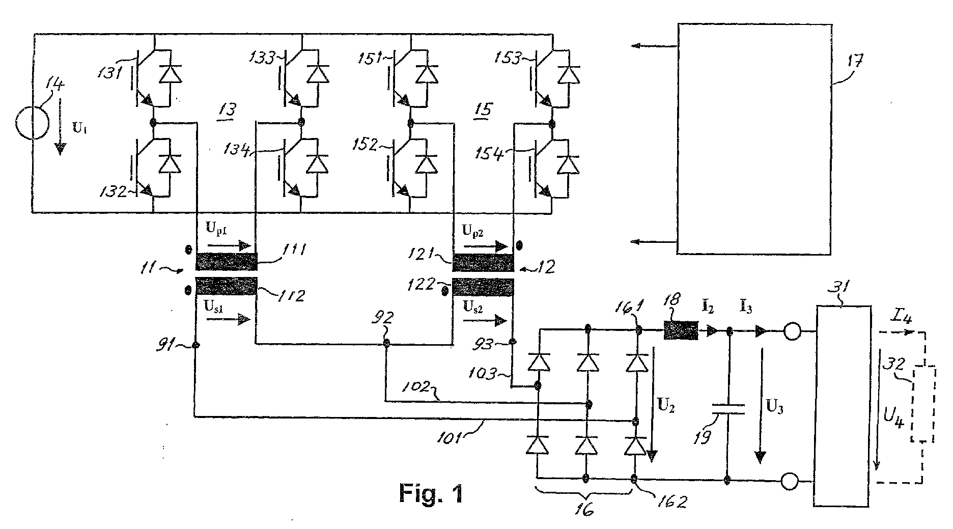
- Figure 1 shows the basic structure of a power supply according to the invention.
- Fig. 1 this power supply a DC-DC converter which comprises two transformers 11 and 22 having each one primary and one secondary winding, a 6-diode-bridge rectifier 16 and control means 17 for providing suitable control pulses which make possible a specified control sequence of two H-bridge switching circuits which thereby connect those transformers to a primary DC source 14 of electrical energy during selected time intervals.
- Fig. 2 shows a typical structure of primary DC source 14.
- Primary DC source 14 provides a voltage U 1 .
- Primary DC source 14 receives AC electrical energy through power lines 24, 25, 26, comprises e.g. a 6-diode bridge rectifier circuit, and a filter formed by an inductor 28 and a capacitor 29.
- this embodiment comprises a filtering inductor 18 connected in series with one of the terminal outputs of the bridge rectifier 16.
- the DC-DC converter of the power supply shown in Fig. 1 comprises:
- Each of the switching elements 131, 132, 133, 134, 151, 152, 153, 154, and switching elements 231, 232, 233, 234 mentioned below with reference to Fig. 5 is e.g. an IGBT or a MOSFET and is connected in parallel with a diode as shown in the accompanying drawings.
- First transformer 11 has a primary winding 111 and a secondary winding 112.
- the primary winding and the secondary winding of first transformer 11 have the same winding polarity.
- Second transformer 12 has a primary winding 121 and a secondary winding 122.
- the primary winding and the secondary winding of the second transformer 12 have opposite winding polarities.
- the secondary winding 112 of first transformer 11 has a terminal which is a first transformer output terminal 91.
- Another terminal of secondary winding 112 of first transformer 11 and a terminal of secondary winding 122 of second transformer 12 are connected with each other at a node which is a second transformer output terminal 92.
- the secondary winding of the second transformer 12 has a terminal which is a third transformer output terminal 93.
- the first H-bridge switching circuit 13 serves for selectively connecting the output of the primary DC source 14 to the primary winding 111 of the first transformer 11.
- the first H-bridge switching circuit 13 has a leading leg comprising switching elements 131, 132 and a lagging leg comprising switching elements 133, 134.
- the second H-bridge switching circuit 15 serves for selectively connecting the output of the primary DC source to the primary winding of the second transformer.
- the second H-bridge switching circuit 15 has a leading leg comprising switching elements 151, 152 and a lagging leg comprising switching elements 153, 154.
- the bridge rectifier circuit 16 is a 6-diode-bridge rectifier circuit having the configuration shown by Fig. 1.
- Bridge rectifier circuit 16 has a first input terminal 101 connected to the first transformer output terminal 91, a second input terminal 102 connected to the second transformer output terminal 92, a third input terminal 103 connected to the third transformer output terminal 93, and output terminals 161, 162 adapted to provide electrical energy to an electrical load 32, optionally via a filter formed e.g. by an inductor 18 and a capacitor 19, and a so called “arc control" circuit 31 which is designed to prevent the formation of electrical arcs during a DC plasma processing.
- arc control circuit 31 is a known circuit and is therefore not described in detail.
- Control circuit 17 is adapted to provide the following control pulses:
- this third phase delay is equal to the first phase delay, e.g. phase delay DELTA-1.
- control pulses of all above mentioned sets of control pulses have all one and the same predetermined duration.
- parallel mode a first mode of operation called parallel mode and a second mode of operation called parallel/serial mode, are described hereinafter.
- a smooth and practically continuous transition from the first mode into the second mode of operation is attainable by suitable selection and adjustment of the phases of the control pulses used to control the switching elements of the H-bridge switching circuits, the selection and adjustment being effected by means of the control circuit which provides the control pulses.
- the phases of the control pulses are adjusted e.g. by means of a so called pulse width modulation (PWM).
- PWM pulse width modulation
- Fig. 3 shows a representation of the control pulses used to control the switching elements of the first and second H-bridge switching circuits 13, 15 shown in Fig. 1, as well as a schematic representation of the corresponding waveforms of primary winding voltages U p1 of first transformer 11 and U p2 second transformer 12.
- the leading leg of the first H-bridge switching circuit comprises two switching elements 131, 132.
- a first set of control pulses 131a, 132a switch switching elements 131, 132 ON and OFF alternately with a duty cycle of about 50% (if a safety dead time between them is disregarded).
- the lagging leg of the first H-bridge switching circuit 13 comprises two switching elements 133, 134.
- a second set of control pulses 133a, 134a switch switching elements 133, 134 ON and OFF alternately also with a duty cycle of about 50% (if a safety dead time between them is disregarded).
- the second set of control pulses 133a, 134a has a phase delay DELTA-1 (phase delay ⁇ 1 shown in the drawings) with respect to the first set of control pulses 131a, 132a.
- the leading leg of the second H-bridge 15 switching circuit comprises two switching elements 151, 152.
- a third set of control pulses 151a, 152a switch switching elements 151, 152 ON and OFF alternately with a duty cycle of about 50% (if a safety dead time between them is disregarded).
- the lagging leg of the second H-bridge switching circuit comprises two switching elements 153, 154.
- the third set of control pulses 151a, 152a has a phase delay ALPHA-1 (phase delay ⁇ 1 shown in the drawings) with respect to the first set of control pulses 131a, 132a, and the fourth set of control pulses 153a, 154a has a phase delay DELTA-1 (phase delay ⁇ 1 shown in the drawings) with respect to the third set of control pulses 151a, 152a.
- the secondary windings 112 and 122 of transformers 11 and 12 are connected with each other and with 6-diode-bridge rectifier circuit 16 as shown in Fig. 1.
- the waveform of the output U 2 of bridge rectifier 16 is represented in Fig. 3 under the representation of the waveform of U p2 .
- the value of DELTA is chosen smaller than 90 degrees and the value of ALPHA is chosen equal to 90 degrees.
- phase delay DELTA-1 By continuously varying the value of the phase delay DELTA-1, it is possible to obtain a corresponding continuous variation of the average output voltage provided at the output of the bridge rectifier 16.
- phase delay ALPHA-1 equal to 90 degrees has for consequence that secondary voltages of transformers 11 and 12 are rectified one after the other and therefore the rectified voltage provided at the output of bridge rectifier 16 has a frequency which is four times the switching frequency of the H-bridge switching circuits 13, 15.
- This provides either a minimization of the ripple of the output current provided by the power supply or a reduction of the size of the filtering inductor used in a conventional power supply for the same amount of electrical power delivered to the load.
- the above described first mode of operation (parallel mode) is suitable when a relatively low output voltage is required.
- Fig. 4 shows diagrams similar and corresponding to those shown in Fig. 3, but for phase delays DELTA-2 ( ⁇ 2 shown in Fig. 4) and ALPHA-2 ( ⁇ 2 shown in Fig. 4) which differ from the values of the phase delays DELTA-1 and ALPHA-1 respectively shown in Fig. 3.
- the value of DELTA-2 is chosen between 90 and 180 degrees and the value of ALPHA-2 is chosen equal to DELTA-2.
- the first set of control pulses is 131b, 132b
- the second set of control pulses is 133b, 134b
- the third set of control pulses is 151b, 152b
- the fourth set of control pulses is 153b, 154b.
- phase delay ALPHA-2 delay is equal to phase delay DELTA-2 and is greater than 90 degrees the electrical energy sources represented by the secondary windings of the transformers 11 and 12 are in parallel during predetermined time intervals and in series during other predetermined time intervals.
- the secondary winding 122 of the second transformer 12 is of opposite polarity with respect to the primary winding 121 of the second transformer 12, and the primary and secondary windings of the first transformer 11 have the same polarity. Due to this arrangement, the voltages across the secondary windings of the first and second transformers 11, 12 have opposite polarity and the corresponding rectified voltages add together during predetermined time intervals. Due to this, the output voltage of the bridge rectifier will be the double of one of the voltages across a secondary winding of one of the transformers 11, 12 during those intervals.
- the ripple frequency is twice the switching frequency of the H-bridge switching circuits.
- the magnitude of the square voltage is twice lower than in the case of a conventional power supply.
- the ripple is lower than the ripple obtained with a conventional power supply having the same output filter.
- the above described second mode of operation (parallel/serial mode) is suitable when a higher output voltage is required than the one obtainable with the first mode of operation.
- Fig. 5 schematically shows the basic structure of this second embodiment which is a variant of the basic circuit structure of the first embodiment represented in Fig. 1.
- the embodiment shown by Fig. 5 comprises two half bridge switching circuits 23a and 23b and a primary winding terminal of each of transformers 11 and 12 is connected to a node which is a middle point of a capacitive voltage divider formed by capacitors 33 and 34.
- the output voltage obtained with this configuration is only half the value of the output voltage obtained with configuration with two H-bridge switching circuits of the type shown by Fig. 1.
- Half bridge switching circuits 23a and 23b serve for selectively connecting primary DC source 14 to the primary winding of the first transformer 11 and to the primary winding of the second transformer 12.
- Half bridge switching circuit 23a constitutes a first leg which includes switching elements 231 and 232 and half bridge switching circuit 23b constitutes a second leg which includes switching elements 231 and 232.
- a circuit formed by a series connection of a first capacitor 33 and a second capacitor 34 is connected in parallel with the first leg 231, 232 and with the second leg 233, 234, and that circuit has a node to which a terminal of capacitor 33 and a terminal of capacitor 34 are connected to.
- the latter node is connected to a terminal of each of the primary windings of transformers 11 and 12.
- Fig. 5 comprises a bridge rectifier circuit 16 of the same type described above with reference to Fig. 1 and a control circuit 17 which provides sets of control pulses shown in Figures 6 and 7.
- Control circuit provides e.g. the following sets of control pulses shown e.g. in Fig. 6:
- the adjustable duration of each of the control pulses of the second set of control pulses is equal to the adjustable duration of each of the control pulses of the first set of control pulses.
- the control of the switching elements shown in Fig. 5 is to some extent similar to the control of the switching elements shown in Fig. 1.
- the first set of control pulses is 231a, 232a and the second set of control pulses is 233a, 234a.
- the second set of control pulses 233a, 234a has a predetermined phase delay DELTA-3 ( ⁇ 3 in Fig. 6), with respect to the first set of control pulses 231a, 232a.
- the first set of control pulses is 231b, 232b and the second set of control pulses is 233b, 234b.
- the second set of control pulses 233b, 234b has a predetermined phase delay DELTA-4 ( ⁇ 4 in Fig. 7), with respect to the first set of control pulses 231b, 232b.
- DELTA-3 is chosen equal to 90 degrees
- DELTA-4 is chosen equal to TAU-2.
- Fig. 8 shows an example of a combination of a plurality of DC-DC converters having the basic structure described above with reference to Figures 1 to 4 or of a plurality of DC-DC converters having the basic structure described above with reference to Figures 5 to 7 in order to build a power supply having enhanced power supply capabilities, e.g. a higher range of output voltage and/or output current, and having the above mentioned inherent advantages of those basic structures.
- a power supply having enhanced power supply capabilities e.g. a higher range of output voltage and/or output current, and having the above mentioned inherent advantages of those basic structures.
- the combined structure can thus comprise 2, 4, 6 and in general 2N transformers.
- This embodiment has to a large part the basic structure described above with reference to Fig. 1, but differs therefrom in that it comprises two 4-diode bridge rectifiers 35, 36 instead of the 6-diode bridge rectifier 16 shown by Fig. 1.
- Bridge rectifier circuit 35 includes four diodes and has
- Bridge rectifier circuit 36 includes four diodes and has
- the combined bridge rectifier circuit 35-36 has output terminals 361, 362.
- Fig. 10 shows an example of a combination of a plurality of DC-DC converters having the basic structure described above with reference to Fig. 9 in order to build a power supply having enhanced power supply capabilities, e.g. a higher range of output voltage and/or output current, and having the above mentioned inherent advantages of those basic structures.
- one or more structures comprising each a transformer and a four-diode bridge rectifier are combined with the basic structure represented in Fig. 9 as shown by Fig. 10.
- the combined structure can thus comprise 2, 3, 4, and in general N transformers, the minimum number being 2 transformers.
- Fig. 11 shows a sixth embodiment which is a variant of the basic circuit structure of the first embodiment represented in Fig. 1 and differs therefrom in that it comprises an additional inductor 113, 123 (typical value 50 microhenry) connected in series with each of the primary windings 111, 121 of transformers 11 and 22, and a capacitor connected in parallel with each of the switching elements.
- these capacitors are designated with reference numbers 41 to 48.
- a typical value for each of these capacitors is 2 to 4 nanofarad.
- Inductors 113, 123 shown in Fig. 11 are used to achieve a so called Zero Voltage Switching (ZVS)
- inductors 113, 123 (so called ZVS inductors) needs some time to pass from the positive to the negative direction and vice versa.
- this embodiment also comprises a filtering inductor 11 connected in series with one of the terminal outputs of bridge rectifier 16.
- Fig. 12 schematically shows a seventh embodiment which is a variant of the circuit structure of the sixth embodiment represented in Fig. 11 and differs therefrom in that
- a first effect is that the leakage inductance 114 (124), now the ZVS inductance, of the transformer is used not only for the purpose of ZVS, but also for the performing the filtering of the output signal provided by the power supply.
- a second effect is that the voltage on capacitor 39 across the output of bridge rectifier 16 is the output voltage, that this voltage corresponds to the transformer secondary voltage and therefore also corresponds to the voltage across the primary winding of the transformer, then the primary winding is not anymore short-circuited. Therefore, eventually the resetting of the ZVS inductance current will be very short and therefore the loss in duty cycle capability is substantially reduced.
Landscapes
- Engineering & Computer Science (AREA)
- Power Engineering (AREA)
- Dc-Dc Converters (AREA)
- Plasma Technology (AREA)
- Generation Of Surge Voltage And Current (AREA)
- Arc Welding Control (AREA)
- Emergency Protection Circuit Devices (AREA)
Abstract
Description
- The invention concerns a power supply and in particular a power supply suitable for DC and pulsed DC plasma processing.
- A conventional power supply has the structure shown by Fig. 13 and comprises a H-
bridge switching circuit 51, atransformer 52, arectifier 54 and a filter formed by aninductor 55 and acapacitor 56. Fig. 18 shows a typical output characteristic of such a conventional power supply. As can be appreciated from Fig. 18 such an output characteristic is not suitable for applications in which the electrical load connected to the power supply varies in a broad range, like e.g. in the case of DC plasma processing where the electrical load represented by the plasma does indeed vary in a broad range. Fig. 18 shows that if the electrical load represented by the plasma requires a lower voltage and a higher current, the current capability of a conventional power supply of the type shown by Fig. 13 is relatively limited. - Prior art power supplies for DC plasma processing follow two different approaches in order to enhance the range of DC current delivered to the electrical load represented by the plasma and to obtain an output characteristic of the type represented by Fig. 19.
- In a first prior art approach illustrated by Figures 14 and 15, the power supply has e.g. the basic structure shown by Fig. 14 which only differs from the conventional power supply shown by Fig. 13 in that a
transformer 53 having aprimary winding 531 and several secondary windings, e.g. twosecondary windings transformer 52 in Fig. 13. -
Secondary windings - In order to increase the voltage range of the power supply shown by Fig. 14 it is necessary to change the connection of the
secondary windings - If the DC plasma processing requires to have two or more plasma types it is necessary to have two or more preconfigured power supplies in order to reduce time loss during the process. The first prior art approach is thus expensive.
- In a second prior art approach illustrated by Figures 16 and 17, the power supply has a similar structure as in Figures 14 and 15, but comprises in
addition switches secondary windings secondary windings - A main aim of the instant invention is to provide a power supply and in particular a power supply suitable for DC plasma processing.
- A further aim of the invention is to provide a power supply which is able to provide a constant electrical power to an electrical load which varies within a broad range without having to change the hardware configuration of the power supply or to use different arrangements of power supplies for different ranges of electrical power, voltage and current to be applied to such an electrical load.
- A further aim of the invention is to provide a power supply which is in particular able to provide a desired constant electrical power for any value of the variable voltage across the electrical load represented by a plasma.
- According to the invention the above aim is achieved with a power supply defined by
claims 1 or 4. Preferred embodiments of a power supply according to the invention are defined byclaims 2, 3 and 5 to 16. - A power supply according to the invention is apt to provide a constant electrical power to an electrical load which for a given voltage varies within a broad range in a ratio of 1 to 10 or more, e.g. the electrical load represented by a plasma. Thus for a given voltage, a power supply according to the invention is apt to satisfy a corresponding variation of the current to be supplied to such an electrical load.
- Moreover, a power supply according to the invention is in particular apt to provide a desired constant electrical power for any value of the variable voltage across a plasma.
- The subject invention will now be described in terms of its preferred embodiments. These embodiments are set forth to aid the understanding of the invention, but are not to be construed as limiting.
- Fig. 1 shows a first embodiment of a power supply according to the invention,
- Fig. 2 shows a circuit of a
primary DC source 14 shown in Fig. 1, - Fig. 3 shows in particular control pulses used for
controlling the switching elements of
bridges - Fig. 4 shows in particular control pulses used for
controlling the switching elements of
bridges - Fig. 5 shows a second embodiment of a power supply according to the invention,
- Fig. 6 shows in particular control pulses used for
controlling the switching elements of
half bridges - Fig. 7 shows in particular control pulses used for
controlling the switching elements of
half bridges - Fig. 8 shows a third embodiment of a power supply according to the invention,
- Fig. 9 shows a fourth embodiment of a power supply according to the invention,
- Fig. 10 shows a fifth embodiment of a power supply according to the invention,
- Fig. 11 shows a sixth embodiment of a power supply according to the invention,
- Fig. 12 shows a seventh embodiment of a power supply according to the invention,
- Fig. 13 shows the structure of a conventional power supply,
- Fig. 14 shows a first connection of secondary windings according to a first prior art approach for enhancing the capabilities of a conventional power supply,
- Fig. 15 shows a second connection of secondary windings according to the first prior art approach illustrated by Fig. 14,
- Fig. 16 shows a first connection of secondary windings according to a second prior art approach for enhancing the capabilities of a conventional power supply,
- Fig. 17 shows a second connection of secondary windings according to a second prior art approach for enhancing the capabilities of a conventional power supply,
- Fig. 18 shows a typical U-I output characteristic of a conventional power supply of the type shown by Fig. 13,
- Fig. 19 shows a typical U-I output characteristic of a power supply according to a first prior art approach represented in Figures 14 and 15, or according to a second prior art approach represented in Figures 16 and 17,
- Fig. 20 shows a typical U-I output characteristic of a power supply according to the invention.
-
- This embodiment is described with reference to Figures 1 to 4.
- Figure 1 shows the basic structure of a power supply according to the invention.
- As can be appreciated from Fig. 1 this power supply a DC-DC converter which comprises two
transformers bridge rectifier 16 and control means 17 for providing suitable control pulses which make possible a specified control sequence of two H-bridge switching circuits which thereby connect those transformers to aprimary DC source 14 of electrical energy during selected time intervals. Fig. 2 shows a typical structure ofprimary DC source 14.Primary DC source 14 provides a voltage U1. -
Primary DC source 14 receives AC electrical energy throughpower lines inductor 28 and acapacitor 29. - As can be appreciated from Fig. 1, this embodiment comprises a
filtering inductor 18 connected in series with one of the terminal outputs of thebridge rectifier 16. - As will become apparent from the following description the DC-DC converter shown in Fig. 1 makes possible
- to establish a parallel connection or a serial
connection of the energy sources represented by the outputs
of the
transformers - to effect a smooth and practically continuous transition from the parallel connection to the serial connection or vice versa.
- These effects obtained with the DC-DC converter shown in Fig. 1 give the power supply according to the invention the capability of providing a constant electrical power to an electrical load, e.g. a plasma, the impedance of which varies within a relatively broad range. This can be appreciated from Fig. 20 which shows a typical U-I output characteristic of a power supply according to the invention.
- The DC-DC converter of the power supply shown in Fig. 1 comprises:
- a
first transformer 11 and asecond transformer 12, - a first H-
bridge switching circuit 13 comprisingswitching elements - a second H-
bridge switching circuit 15 comprisingswitching elements - a
bridge rectifier circuit 16, and - a
control circuit 17. - Each of the switching
elements elements -
First transformer 11 has a primary winding 111 and a secondary winding 112. The primary winding and the secondary winding offirst transformer 11 have the same winding polarity. -
Second transformer 12 has a primary winding 121 and a secondary winding 122. The primary winding and the secondary winding of thesecond transformer 12 have opposite winding polarities. - The secondary winding 112 of
first transformer 11 has a terminal which is a firsttransformer output terminal 91. - Another terminal of secondary winding 112 of
first transformer 11 and a terminal of secondary winding 122 ofsecond transformer 12 are connected with each other at a node which is a secondtransformer output terminal 92. - The secondary winding of the
second transformer 12 has a terminal which is a thirdtransformer output terminal 93. - The first H-
bridge switching circuit 13 serves for selectively connecting the output of theprimary DC source 14 to the primary winding 111 of thefirst transformer 11. The first H-bridge switching circuit 13 has a leading leg comprising switchingelements elements - The second H-
bridge switching circuit 15 serves for selectively connecting the output of the primary DC source to the primary winding of the second transformer. The second H-bridge switching circuit 15 has a leading leg comprising switchingelements elements - The
bridge rectifier circuit 16 is a 6-diode-bridge rectifier circuit having the configuration shown by Fig. 1.Bridge rectifier circuit 16 has afirst input terminal 101 connected to the firsttransformer output terminal 91, a second input terminal 102 connected to the secondtransformer output terminal 92, athird input terminal 103 connected to the thirdtransformer output terminal 93, andoutput terminals electrical load 32, optionally via a filter formed e.g. by aninductor 18 and acapacitor 19, and a so called "arc control"circuit 31 which is designed to prevent the formation of electrical arcs during a DC plasma processing. Within the scope of the present description "arc control"circuit 31 is a known circuit and is therefore not described in detail. -
Control circuit 17 is adapted to provide the following control pulses: - a first set of control pulses,
e.g. pulses elements bridge switching circuit 13, - a second set of control pulses , e.g. pulses 133a
and 134a in Fig. 3 for effecting switching of switching
elements bridge switching circuit 13, this second set of control pulses having an adjustable first phase delay, e.g. phase delay DELTA-1 (δ1 shown in Fig. 3) with respect to the first set of control pulses, - a third set of control pulses,
e.g. pulses 151a, 152a in Fig. 3 for effecting switching of switchingelements bridge switching circuit 15,
this third set of control pulses having an adjustable second phase delay, e.g. (phase delay ALPHA-1, α1 shown in Fig. 3) with respect to the first set ofcontrol pulses - a fourth set of control pulses, e.g. pulses 153a,
154a in Fig. 3 for effecting switching of switching
elements bridge switching circuit 15,
this fourth set of control pulses having an adjustable third phase delay with respect to the third set of control pulses. - In a preferred embodiment, this third phase delay is equal to the first phase delay, e.g. phase delay DELTA-1.
- In a preferred embodiment, the control pulses of all above mentioned sets of control pulses have all one and the same predetermined duration.
- Two different modes of operation of the above described first embodiment, a first mode of operation called parallel mode and a second mode of operation called parallel/serial mode, are described hereinafter.
- As can be appreciated from the following description, a smooth and practically continuous transition from the first mode into the second mode of operation is attainable by suitable selection and adjustment of the phases of the control pulses used to control the switching elements of the H-bridge switching circuits, the selection and adjustment being effected by means of the control circuit which provides the control pulses. The phases of the control pulses are adjusted e.g. by means of a so called pulse width modulation (PWM).
- Fig. 3 shows a representation of the control pulses used to control the switching elements of the first and second H-
bridge switching circuits first transformer 11 and Up2second transformer 12. - The leading leg of the first H-bridge switching circuit comprises two switching
elements - A first set of
control pulses switch switching elements - The lagging leg of the first H-
bridge switching circuit 13 comprises two switchingelements switch switching elements - As can be appreciated from Fig. 3, the second set of control pulses 133a, 134a has a phase delay DELTA-1 (phase delay δ1 shown in the drawings) with respect to the first set of
control pulses - The above described switching of the switching elements of the first H-bridge switching circuit provides a voltage Up1 across the primary winding 111 of
first transformer 11. Voltage Up1 has a waveform which is schematically represented in Fig. 3. - The leading leg of the second H-
bridge 15 switching circuit comprises two switchingelements control pulses 151a, 152aswitch switching elements - The lagging leg of the second H-bridge switching circuit comprises two switching
elements switch switching elements - As can be appreciated from Fig. 3, the third set of
control pulses 151a, 152a has a phase delay ALPHA-1 (phase delay α1 shown in the drawings) with respect to the first set ofcontrol pulses control pulses 151a, 152a. - The above described switching of the switching elements of the second H-
bridge switching circuit 15 provides a voltage Up2 across the primary winding 121 ofsecond transformer 12. Voltage Up2 has a waveform which is schematically represented in Fig. 3. - The
secondary windings transformers bridge rectifier circuit 16 as shown in Fig. 1. - The waveform of the output U2 of
bridge rectifier 16 is represented in Fig. 3 under the representation of the waveform of Up2. - Fig. 3 illustrates the case where DELTA-1 = 45 degrees and ALPHA-1 = 90 degrees. In general for the first mode of operation (parallel mode) the value of DELTA is chosen smaller than 90 degrees and the value of ALPHA is chosen equal to 90 degrees.
- By continuously varying the value of the phase delay DELTA-1, it is possible to obtain a corresponding continuous variation of the average output voltage provided at the output of the
bridge rectifier 16. - The choice of a phase delay ALPHA-1 equal to 90 degrees has for consequence that secondary voltages of
transformers bridge rectifier 16 has a frequency which is four times the switching frequency of the H-bridge switching circuits - This provides either a minimization of the ripple of the output current provided by the power supply or a reduction of the size of the filtering inductor used in a conventional power supply for the same amount of electrical power delivered to the load.
- The above described first mode of operation (parallel mode) is suitable when a relatively low output voltage is required.
- An example of the sets of control pulses used to obtain this mode of operation is shown in Fig. 4 which shows diagrams similar and corresponding to those shown in Fig. 3, but for phase delays DELTA-2 (δ2 shown in Fig. 4) and ALPHA-2 (α2 shown in Fig. 4) which differ from the values of the phase delays DELTA-1 and ALPHA-1 respectively shown in Fig. 3.
- In the example illustrated by Fig. 4 DELTA-2 = 135 degrees and ALPHA-2 = 135 degrees. In general for the second mode of operation (parallel/serial mode) the value of DELTA-2 is chosen between 90 and 180 degrees and the value of ALPHA-2 is chosen equal to DELTA-2.
- In Fig. 4 the first set of control pulses is 131b, 132b, the second set of control pulses is 133b, 134b, the third set of control pulses is 151b, 152b, and the fourth set of control pulses is 153b, 154b.
- Fig. 4 also shows a schematic representation of the waveforms of primary winding voltages Up1 and Up2 of the first and the
second transformer - With this second mode of operation it is also possible to obtain a continuous variation of the average output voltage provided at the output of the bridge rectifier by effecting a corresponding continuous variation of the value of the phase delay DELTA-2 and of the phase delay ALPHA-2 = DELTA-2 and the average voltage obtainable at the output of the bridge rectifier is higher than for the first mode of operation and reaches a maximum of twice the voltage provided by a secondary winding of one of the
transformers - As can be appreciated from the example represented by Fig. 4, when phase delay ALPHA-2 delay is equal to phase delay DELTA-2 and is greater than 90 degrees the electrical energy sources represented by the secondary windings of the
transformers - As can be appreciated from Fig. 1, the secondary winding 122 of the
second transformer 12 is of opposite polarity with respect to the primary winding 121 of thesecond transformer 12, and the primary and secondary windings of thefirst transformer 11 have the same polarity. Due to this arrangement, the voltages across the secondary windings of the first andsecond transformers transformers - The ripple frequency is twice the switching frequency of the H-bridge switching circuits. The magnitude of the square voltage is twice lower than in the case of a conventional power supply. The ripple is lower than the ripple obtained with a conventional power supply having the same output filter.
- The above described second mode of operation (parallel/serial mode) is suitable when a higher output voltage is required than the one obtainable with the first mode of operation.
- As can be appreciated from the foregoing description, a smooth and practically continuous transition from the first mode into the second mode of operation is attainable by suitable selection and adjustment of the phases of the control pulses used to control the switching elements of the H-bridge switching circuits, the selection and adjustment being effected by means of the
control circuit 17 which provides the control pulses. - This embodiment is described with reference to Figures 5 to 7.
- Fig. 5 schematically shows the basic structure of this second embodiment which is a variant of the basic circuit structure of the first embodiment represented in Fig. 1.
- The embodiment shown by Fig. 5 comprises two half
bridge switching circuits transformers capacitors - The two half
bridge switching circuits primary DC source 14 to the primary winding of thefirst transformer 11 and to the primary winding of thesecond transformer 12. Halfbridge switching circuit 23a constitutes a first leg which includes switchingelements bridge switching circuit 23b constitutes a second leg which includes switchingelements - A circuit formed by a series connection of a
first capacitor 33 and asecond capacitor 34 is connected in parallel with thefirst leg second leg capacitor 33 and a terminal ofcapacitor 34 are connected to. The latter node is connected to a terminal of each of the primary windings oftransformers - The embodiment shown by Fig. 5 comprises a
bridge rectifier circuit 16 of the same type described above with reference to Fig. 1 and acontrol circuit 17 which provides sets of control pulses shown in Figures 6 and 7. - Control circuit provides e.g. the following sets of control pulses shown e.g. in Fig. 6:
- a first set of
control pulses elements bridge switching circuit 23a, each of the control pulses of the first set having an adjustable duration, - a second set of
control pulses elements bridge switching circuit 23b, each of the control pulses of the second set having an adjustable duration, - In a preferred embodiment the adjustable duration of each of the control pulses of the second set of control pulses is equal to the adjustable duration of each of the control pulses of the first set of control pulses.
- The control of the switching elements shown in Fig. 5 is to some extent similar to the control of the switching elements shown in Fig. 1.
- Fig 6 shows the sets of control pulses for the parallel mode of the embodiment shown by Fig. 5 with a control pulse duration TAU-1 = 45 degrees (τ1 = 45 degrees).
- In Fig. 6 the first set of control pulses is 231a, 232a and the second set of control pulses is 233a, 234a. The second set of
control pulses control pulses - Fig 7 shows the sets of control pulses for the parallel/serial mode of this embodiment with a control pulse duration TAU-2 = 135 degrees (τ2= 135 degrees) .
- In Fig. 7 the first set of control pulses is 231b, 232b and the second set of control pulses is 233b, 234b. The second set of
control pulses control pulses - In a preferred embodiment when TAU-1 is smaller than 90 degrees, then DELTA-3 is chosen equal to 90 degrees, and when TAU-2 is greater than 90 degrees, then DELTA-4 is chosen equal to TAU-2.
- This embodiment is described with reference to Fig. 8.
- Fig. 8 shows an example of a combination of a plurality of DC-DC converters having the basic structure described above with reference to Figures 1 to 4 or of a plurality of DC-DC converters having the basic structure described above with reference to Figures 5 to 7 in order to build a power supply having enhanced power supply capabilities, e.g. a higher range of output voltage and/or output current, and having the above mentioned inherent advantages of those basic structures. For this purpose one or more basic structures according to Fig. 1 or to Fig. 5 are combined as shown by Fig. 8. The combined structure can thus comprise 2, 4, 6 and in general 2N transformers.
- This embodiment is described with reference to Fig. 9.
- This embodiment has to a large part the basic structure described above with reference to Fig. 1, but differs therefrom in that it comprises two 4-
diode bridge rectifiers diode bridge rectifier 16 shown by Fig. 1. -
Bridge rectifier circuit 35 includes four diodes and has - a
first input terminal 101 connected to the firsttransformer output terminal 91, and - a second input terminal 102 connected to the second
transformer output terminal 92. -
-
Bridge rectifier circuit 36 includes four diodes and has - a
first input terminal 103 connected to the secondtransformer output terminal 92, and - a
second input terminal 104 connected to the thirdtransformer output terminal 93. -
- The combined bridge rectifier circuit 35-36 has
output terminals - This embodiment is described with reference to Fig. 10.
- Fig. 10 shows an example of a combination of a plurality of DC-DC converters having the basic structure described above with reference to Fig. 9 in order to build a power supply having enhanced power supply capabilities, e.g. a higher range of output voltage and/or output current, and having the above mentioned inherent advantages of those basic structures. For this purpose one or more structures comprising each a transformer and a four-diode bridge rectifier are combined with the basic structure represented in Fig. 9 as shown by Fig. 10. The combined structure can thus comprise 2, 3, 4, and in general N transformers, the minimum number being 2 transformers.
- This embodiment is described with reference to Fig. 11.
- Fig. 11 shows a sixth embodiment which is a variant of the basic circuit structure of the first embodiment represented in Fig. 1 and differs therefrom in that it comprises an additional inductor 113, 123 (typical value 50 microhenry) connected in series with each of the
primary windings transformers reference numbers 41 to 48. A typical value for each of these capacitors is 2 to 4 nanofarad. - Inductors 113, 123 shown in Fig. 11 are used to achieve a so called Zero Voltage Switching (ZVS)
- The current flowing through inductors 113, 123 (so called ZVS inductors) needs some time to pass from the positive to the negative direction and vice versa.
- Specially during the switching OFF of the leading leg of a H-bridge, the current flowing through the
inductance 18 will flow through therectifier bridge 16 that will free wheel and short circuit the secondary winding of the transformer and thereby also the primary of the transformer, and due to this effect a very long time is needed for resetting the current flowing through a ZVS inductor. This time requirement causes a loss in duty cycle capability and therefore a loss in output voltage capability. These phenomena do not allow the obtention of twice the output voltage across the secondary winding when the above mentioned the phase delay DELTA is equal to 180 degrees (loss in duty cycle capability). - As can be appreciated from Fig. 11, this embodiment also comprises a
filtering inductor 11 connected in series with one of the terminal outputs ofbridge rectifier 16. - This embodiment is described with reference to Fig. 12.
- Fig. 12 schematically shows a seventh embodiment which is a variant of the circuit structure of the sixth embodiment represented in Fig. 11 and differs therefrom in that
- each of the additional inductors L1 which are
connected in series with each of the primary windings of
transformers transformer 11 respectively 12, and
thefiltering inductor 18 connected to the output ofbridge rectifier 16 is eliminated, that is the output of the bridge rectifier is connected directly to anoutput capacitor 39 as shown by Fig. 12. - Removal of the
filtering inductor 18 and connection of the output capacitor 39 (typical value 0.5 microfarad) directly across the output ofbridge rectifier 16 has two effects. A first effect is that the leakage inductance 114 (124), now the ZVS inductance, of the transformer is used not only for the purpose of ZVS, but also for the performing the filtering of the output signal provided by the power supply. A second effect is that the voltage oncapacitor 39 across the output ofbridge rectifier 16 is the output voltage, that this voltage corresponds to the transformer secondary voltage and therefore also corresponds to the voltage across the primary winding of the transformer, then the primary winding is not anymore short-circuited. Therefore, eventually the resetting of the ZVS inductance current will be very short and therefore the loss in duty cycle capability is substantially reduced. -
- 11
- transformer
- 12
- transformer
- 13
- H-bridge switching circuit
- 14
- primary DC source
- 15
- H-bridge switching circuit
- 16
- bridge rectifier circuit
- 17
- control circuit
- 18
- inductor
- 19
- capacitor
- 20 21
- transformer
- 22
- transformer
- 23a
- half bridge switching circuit
- 23b
- half bridge switching circuit
- 24
- power line
- 25
- power line
- 26
- power line
- 27
- bridge rectifier circuit
- 28
- inductor
- 29
- capacitor
- 30 31
- "arc control" circuit
- 32
- electrical load
- 33
- capacitor
- 34
- capacitor
- 35
- bridge rectifier circuit
- 36
- bridge rectifier circuit
- 37 38 39
- capacitor
- 40 41
- capacitor
- 42
- capacitor
- 43
- capacitor
- 44
- capacitor
- 45
- capacitor
- 46
- capacitor
- 47
- capacitor
- 48
- capacitor
- 49 50 51
- H-bridge switching circuit
- 52
- transformer
- 53
- transformer
- 54
- rectifier
- 55
- inductor
- 56 57 58 59 60
- capacitor
- 91
- transformer output terminal
- 92
- transformer output terminal
- 93
- transformer output terminal
- 100 101
- input terminal of bridge rectifier
- 102
- input terminal of bridge rectifier
- 103
- input terminal of bridge rectifier
- 104
- input terminal of bridge rectifier
- 111
- primary winding
- 112
- secondary winding
- 113
- inductor
- 114
- leakage inductance of
transformer 11 seen from its primary winding - 121
- primary winding
- 122
- secondary winding
- 123
- inductor
- 124
- leakage inductance of
transformer 12 seen from its primary winding - 131
- switching element
- 132
- switching element
- 133
- switching element
- 134
- switching element
- 151
- switching element
- 152
- switching element
- 153
- switching element
- 154
- switching element
- 161
- output terminal
- 162
- output terminal
- 231
- switching element
- 232
- switching element
- 233
- switching element
- 234
- switching element
- 361
- output terminal
- 362
- output terminal
- 531
- primary winding
- 532
- secondary winding
- 533
- secondary winding
- U1
- DC output voltage of
primary DC source 14 - U2
- unfiltered output voltage of
bridge rectifier 16 - U3
- filtered output voltage of
bridge rectifier 16 - U4
- output voltage of "arc control" circuit
- n
- transformer ratio
- I2
- output current of bridge rectifier
- I3
- output current of DC-DC converter
- I4
- output current of "arc control" circuit
- δ
- DELTA, phase delay
- α
- ALPHA, phase delay
- τ
- TAU, duration expressed as a fraction of a period of 360 degrees
- Although a preferred embodiment of the invention has been described using specific terms, such description is for illustrative purposes only, and it is to be understood that changes and variations may be made without departing from the spirit or scope of the following claims.
Claims (16)
- A power supply comprising a DC-DC converter which comprisessaid secondary winding of said first transformer (11) having a terminal which is a first transformer output terminal,(a) a first transformer (11) having a primary winding and a secondary winding, said primary winding and said secondary winding of said first transformer having the same winding polarity;(b) a second transformer (12) having a primary winding and a secondary winding, said primary winding and said secondary winding of said second transformer having opposite winding polarities;
another terminal of said secondary winding of said first transformer (11) and a terminal of said secondary winding of said second transformer (12) being connected with each other at a node which is a second transformer output terminal, and
said secondary winding of said second transformer (12) having a terminal which is a third transformer output terminal;(c) a first H-bridge switching circuit (13) for selectively connecting a primary DC source (14) to the primary winding of said first transformer, said first H-bridge switching circuit (13) having a leading leg and a lagging leg, each of these legs including switching elements;(d) a second H-bridge (15) switching circuit for selectively connecting said primary DC source (14) to the primary winding of said second transformer (12), said second H-bridge switching circuit (15) having a leading leg and a lagging leg, each of these legs including switching elements;(e) a bridge rectifier circuit (16, 35-36) connected to the secondary windings of said first and second transformers (11, 12);(f) a control circuit (17) for providing(f.1) a first set of control pulses (131a, 132a) for effecting switching of switching elements (131, 132) of said leading leg of said first H-bridge switching circuit (13),(f.2) a second set of control pulses (133a, 134a) for effecting switching of switching elements (133, 134) of said lagging leg of said first H-bridge switching circuit (13),
said second set of control pulses having an adjustable first phase delay with respect to said first set of control pulses,(f.3) a third set of control pulses (151a, 152a) for effecting switching of switching elements (151, 152) of said leading leg of said second H-bridge switching circuit (15),
said third set of control pulses having an adjustable second phase delay with respect to said first set of control pulses,(f.4) a fourth set of control pulses (153a, 154a) for effecting switching of switching elements (153, 154) of said lagging leg of said second H-bridge switching circuit (15),
said fourth set of control pulses having an adjustable third phase delay with respect to said third set of control pulses. - A power supply according to claim 1, wherein said third phase delay is equal to said first phase delay.
- A power supply according to claim 1, wherein said control pulses of all said sets of control pulses have all one and the same predetermined duration.
- A power supply comprising a DC-DC converter which comprises
a DC-DC converter which comprisessecond set of control pulses having a predetermined phase delay with respect to said first set of control pulses.(a) a first transformer (11) having a primary winding and a secondary winding, said primary winding and said secondary winding of said first transformer having the same winding polarity;(b) a second transformer (12) having a primary winding and a secondary winding, said primary winding and said secondary winding of said second transformer having opposite winding polarities;
said secondary winding of said first transformer (11) having a terminal which is a first transformer output terminal,
another terminal of said secondary winding of said first transformer (11) and a terminal of said secondary winding of said second transformer (12) being connected with each other at a node which is a second transformer output terminal, and
said secondary winding of said second transformer (12) having a terminal which is a third transformer output terminal;(c) a first half bridge switching circuit (23a) and a second half bridge switching circuit (23b) for selectively connecting a primary DC source (14) to the primary winding of said first transformer (11) and to the primary winding of said second transformer (12), said first half bridge switching circuit (23a) forming a first leg, said second half bridge switching circuit (23b) forming a second leg, each of these legs including switching elements;(d) a circuit formed by a series connection of a first capacitor (33) and a second capacitor (34), said circuit being connected in parallel with said first leg and with said second leg,
said circuit formed by said series connection of said first capacitor (33) and said second capacitor (34) having a node to which a terminal of each of said first and second capacitors is connected to,
said node being connected to a terminal of each of said primary windings of said first and said second transformers (11, 12);(e) a bridge rectifier circuit (16, 35-36) connected to the secondary windings of said first and second transformers (11, 12);(f) a control circuit (17) for providing(f.1) a first set of control pulses for effecting switching of switching elements of said first leg formed by said first half bridge switching circuit (23a), each of said control pulses of said first set having an adjustable duration,(f.2) a second set of control pulses for effecting switching of switching elements of said second leg formed by said second half bridge switching circuit (23b), each of said control pulses of said second set having an adjustable duration, - A power supply according to claim 4, wherein said adjustable duration of each of the control pulses of said second set of control pulses is equal to said adjustable duration of each of the control pulses of said first set of control pulses.
- A power supply according to any of claims 1 to 5, wherein said bridge rectifier circuit (16) includes six diodes and hasa first input terminal (101) connected to said first transformer output terminal,a second input terminal (102) connected to said second transformer output terminal,a third input terminal (103) connected to said third transformer output terminal, andoutput terminals (161, 162).
- A power supply comprising a combination of a plurality of DC-DC converters of the kind defined claim 6.
- A power supply according to any of claims 1 to 5, wherein said bridge rectifier circuit (35-36) comprises(i) a first bridge rectifier circuit (35) including four diodes and havinga first input terminal (101) connected to said first transformer output terminal, anda second input terminal (102) connected to said second transformer output terminal,(ii) a second bridge rectifier circuit (36) including four diodes and havinga first input terminal (103) connected to said second transformer output terminal, anda second input terminal (104) connected to said third transformer output terminal, and(iii) output terminals (361, 362).
- A power supply comprising a combination of a plurality of DC-DC converters of the kind defined claim 8.
- A power supply according to any of the preceding claims 1 to 9, further comprising means for performing zero voltage switching of the switching elements of said H-bridge switching circuits (13, 15, 23).
- A power supply according to claim 10, wherein said means for performing zero voltage switching comprise the inductance of a first inductor (113) connected in series with the primary winding of said first transformer (11), the inductance of a second inductor (123) connected in series with the primary winding of said second transformer (12), and a capacitor (41 to 48) connected in parallel with each of the switching elements of each H-bridge switching circuit (13, 15, 23).
- A power supply according to claim 10, wherein the leakage inductance (114) of said first transformer (11) is used instead of said first inductor (113) and/or the leakage inductance (124) of said second transformer (12) is used instead of said second inductor (123).
- A power supply according to claim 12, wherein leakage inductances (114, 124) of said first transformer (11) and said second transformer (12) are exclusively used as inductances for performing said zero voltage switching.
- A power supply according to claim 12, wherein leakage inductances (114, 124) of said first transformer (11) and said second transformer (12) are exclusively used instead of an output filtering inductor (18) which would otherwise be connected in series with an output terminal of said bridge rectifier (16, 35-36).
- A power supply according to any of claims 11 to 14, wherein said means for performing said zero voltage switching further comprise a capacitor (39) connected across the output terminals of said bridge rectifier (16, 35-36), said capacitor (39) serving for reducing the resetting time of said inductances (113, 114, 123, 124) for performing said zero voltage switching.
- A power supply according to any of the preceding claims 1 to 15 characterized in that it is so configured and dimensioned that it is particularly suitable a power supply for plasma processing.
Priority Applications (4)
| Application Number | Priority Date | Filing Date | Title |
|---|---|---|---|
| AT01202697T ATE464692T1 (en) | 2001-07-16 | 2001-07-16 | AN ELECTRICAL POWER SUPPLY PARTICULARLY APPLICABLE FOR DIRECT CURRENT PLASMA TREATMENT |
| DE60141822T DE60141822D1 (en) | 2001-07-16 | 2001-07-16 | An electrical power supply that is particularly applicable for DC plasma treatment |
| EP01202697A EP1278294B9 (en) | 2001-07-16 | 2001-07-16 | An electrical power supply suitable in particular for dc plasma processing |
| US10/185,822 US6567278B2 (en) | 2001-07-16 | 2002-06-27 | Electrical power supply suitable in particular for DC plasma processing |
Applications Claiming Priority (1)
| Application Number | Priority Date | Filing Date | Title |
|---|---|---|---|
| EP01202697A EP1278294B9 (en) | 2001-07-16 | 2001-07-16 | An electrical power supply suitable in particular for dc plasma processing |
Publications (3)
| Publication Number | Publication Date |
|---|---|
| EP1278294A1 true EP1278294A1 (en) | 2003-01-22 |
| EP1278294B1 EP1278294B1 (en) | 2010-04-14 |
| EP1278294B9 EP1278294B9 (en) | 2010-09-01 |
Family
ID=8180642
Family Applications (1)
| Application Number | Title | Priority Date | Filing Date |
|---|---|---|---|
| EP01202697A Expired - Lifetime EP1278294B9 (en) | 2001-07-16 | 2001-07-16 | An electrical power supply suitable in particular for dc plasma processing |
Country Status (4)
| Country | Link |
|---|---|
| US (1) | US6567278B2 (en) |
| EP (1) | EP1278294B9 (en) |
| AT (1) | ATE464692T1 (en) |
| DE (1) | DE60141822D1 (en) |
Cited By (10)
| Publication number | Priority date | Publication date | Assignee | Title |
|---|---|---|---|---|
| WO2006099759A2 (en) | 2005-03-24 | 2006-09-28 | Oerlikon Trading Ag, Trübbach | Vacuum plasma generator |
| EP1727266A2 (en) * | 2005-05-27 | 2006-11-29 | TDK Corporation | Switching power supply unit and voltage converting method |
| WO2007057619A1 (en) * | 2005-11-21 | 2007-05-24 | Renault S.A.S | High-voltage power supply and a plasma reactor |
| EP1816735A2 (en) * | 2006-02-03 | 2007-08-08 | TDK Corporation | Switching power supply unit |
| JP2008533687A (en) * | 2005-03-24 | 2008-08-21 | エリコン・トレーディング・アクチェンゲゼルシャフト,トリュープバッハ | Vacuum plasma generator |
| EP2161823A1 (en) * | 2007-06-28 | 2010-03-10 | Shindengen Electric Manufacturing Co., Ltd. | Bidirectional dc/dc converter |
| CN103391005A (en) * | 2013-07-24 | 2013-11-13 | 深圳市航天新源科技有限公司 | Power-extensible variable-structure converter |
| EP1826895A3 (en) * | 2006-02-28 | 2016-01-13 | TDK Corporation | Switching power supply unit |
| CN110233579A (en) * | 2019-05-23 | 2019-09-13 | 北京动力源科技股份有限公司 | A kind of parallel connection rectification topology and a kind of LLC resonance circuit |
| US20220157581A1 (en) * | 2020-09-10 | 2022-05-19 | Impedans Ltd | Apparatus for ion energy analysis of plasma processes |
Families Citing this family (42)
| Publication number | Priority date | Publication date | Assignee | Title |
|---|---|---|---|---|
| TW591974B (en) * | 2002-11-14 | 2004-06-11 | Richtek Technology Corp | Two-phase H-bridge driving circuit and method |
| US7184146B2 (en) * | 2003-06-24 | 2007-02-27 | Cardinal Ig Company | Methods and apparatus for evaluating insulating glass units |
| DE10330473A1 (en) * | 2003-07-05 | 2005-01-27 | Alstom Technology Ltd | Frequency converter for high-speed generators |
| EP1501180A1 (en) * | 2003-07-23 | 2005-01-26 | ABB Schweiz AG | Converter circuit |
| US20050288739A1 (en) * | 2004-06-24 | 2005-12-29 | Ethicon, Inc. | Medical implant having closed loop transcutaneous energy transfer (TET) power transfer regulation circuitry |
| US20060262574A1 (en) * | 2005-05-20 | 2006-11-23 | David Kelly | DC high voltage to DC low voltage converter |
| US8514601B2 (en) | 2009-08-17 | 2013-08-20 | Ideal Power Converters, Inc. | Power conversion with added pseudo-phase |
| WO2011022442A2 (en) * | 2009-08-17 | 2011-02-24 | Ideal Power Converters Inc. | Power conversion with added pseudo-phase |
| EP2874297B1 (en) | 2006-06-06 | 2023-09-27 | Ideal Power Inc. | Buck-Boost power converter |
| NZ550043A (en) * | 2006-09-21 | 2008-01-31 | Eaton Power Quality Company | A switched mode power supply and method of production |
| US8133359B2 (en) | 2007-11-16 | 2012-03-13 | Advanced Energy Industries, Inc. | Methods and apparatus for sputtering deposition using direct current |
| US9039871B2 (en) | 2007-11-16 | 2015-05-26 | Advanced Energy Industries, Inc. | Methods and apparatus for applying periodic voltage using direct current |
| WO2011008567A2 (en) | 2009-06-29 | 2011-01-20 | Ideal Power Converters, Inc. | Power transfer devices, methods, and systems with crowbar switch shunting energy-transfer reactance |
| KR101073598B1 (en) | 2009-12-17 | 2011-10-14 | 부경대학교 산학협력단 | Multi-parallel Zero-Voltage Switching DC-DC converter and control method therefor |
| KR101140336B1 (en) | 2010-09-28 | 2012-05-03 | 한국전기연구원 | Isolated buck-boost dc-dc converter |
| WO2012075189A2 (en) | 2010-11-30 | 2012-06-07 | Ideal Power Converters Inc. | Photovoltaic array systems, methods, and devices with bidirectional converter |
| US8531858B2 (en) | 2011-02-18 | 2013-09-10 | Ideal Power, Inc. | Power conversion with current sensing coupled through saturating element |
| WO2014084925A1 (en) * | 2012-11-27 | 2014-06-05 | The Board Of Regents Of The University Of Texas System | Rail plasma actuator for high-authority flow control |
| US11539352B2 (en) | 2013-11-14 | 2022-12-27 | Eagle Harbor Technologies, Inc. | Transformer resonant converter |
| US9960763B2 (en) | 2013-11-14 | 2018-05-01 | Eagle Harbor Technologies, Inc. | High voltage nanosecond pulser |
| US10020800B2 (en) | 2013-11-14 | 2018-07-10 | Eagle Harbor Technologies, Inc. | High voltage nanosecond pulser with variable pulse width and pulse repetition frequency |
| US10892140B2 (en) | 2018-07-27 | 2021-01-12 | Eagle Harbor Technologies, Inc. | Nanosecond pulser bias compensation |
| US10978955B2 (en) | 2014-02-28 | 2021-04-13 | Eagle Harbor Technologies, Inc. | Nanosecond pulser bias compensation |
| US10483089B2 (en) | 2014-02-28 | 2019-11-19 | Eagle Harbor Technologies, Inc. | High voltage resistive output stage circuit |
| US11004660B2 (en) | 2018-11-30 | 2021-05-11 | Eagle Harbor Technologies, Inc. | Variable output impedance RF generator |
| US11430635B2 (en) | 2018-07-27 | 2022-08-30 | Eagle Harbor Technologies, Inc. | Precise plasma control system |
| CN115378264A (en) | 2017-02-07 | 2022-11-22 | 鹰港科技有限公司 | Transformer resonant converter |
| KR102208429B1 (en) | 2017-08-25 | 2021-01-29 | 이글 하버 테크놀로지스, 인코포레이티드 | Arbitrary waveform generation using nanosecond pulses |
| CN109873571A (en) * | 2017-12-04 | 2019-06-11 | 邹晓灵 | A kind of general inverter and its control method |
| US11302518B2 (en) | 2018-07-27 | 2022-04-12 | Eagle Harbor Technologies, Inc. | Efficient energy recovery in a nanosecond pulser circuit |
| US10607814B2 (en) * | 2018-08-10 | 2020-03-31 | Eagle Harbor Technologies, Inc. | High voltage switch with isolated power |
| US11532457B2 (en) | 2018-07-27 | 2022-12-20 | Eagle Harbor Technologies, Inc. | Precise plasma control system |
| US11222767B2 (en) | 2018-07-27 | 2022-01-11 | Eagle Harbor Technologies, Inc. | Nanosecond pulser bias compensation |
| KR20230025034A (en) | 2018-08-10 | 2023-02-21 | 이글 하버 테크놀로지스, 인코포레이티드 | Plasma sheath control for rf plasma reactors |
| TW202308306A (en) | 2019-01-08 | 2023-02-16 | 美商鷹港科技股份有限公司 | Method for creating high voltage pulses |
| CN110165896B (en) * | 2019-04-30 | 2020-05-05 | 东南大学 | Direct-current transformer based on centralized multi-winding transformer and control method |
| TWI778449B (en) | 2019-11-15 | 2022-09-21 | 美商鷹港科技股份有限公司 | High voltage pulsing circuit |
| WO2021134000A1 (en) | 2019-12-24 | 2021-07-01 | Eagle Harbor Technologies, Inc. | Nanosecond pulser rf isolation for plasma systems |
| CN114285285A (en) * | 2021-05-10 | 2022-04-05 | 华北电力大学(保定) | Novel wide-voltage gain direct-current transformer based on T-shaped bridge and double transformers |
| CN114244121A (en) * | 2021-11-18 | 2022-03-25 | 北京动力源科技股份有限公司 | DC-DC series-parallel topological structure |
| CN114244122A (en) * | 2021-11-24 | 2022-03-25 | 北京动力源科技股份有限公司 | Half-bridge LLC constant-power wide-range converter topology and circuit |
| CN114244123A (en) * | 2021-11-24 | 2022-03-25 | 北京动力源科技股份有限公司 | Full-bridge LLC constant-power wide-range converter topology and circuit |
Citations (2)
| Publication number | Priority date | Publication date | Assignee | Title |
|---|---|---|---|---|
| US5461297A (en) * | 1993-05-24 | 1995-10-24 | Analog Modules, Inc. | Series-parallel switchable capacitor charging system |
| US5930122A (en) * | 1997-09-17 | 1999-07-27 | Sansha Electric Manufacturing Co., Limited | Inverter and DC power supply apparatus with inverter used therein |
Family Cites Families (7)
| Publication number | Priority date | Publication date | Assignee | Title |
|---|---|---|---|---|
| GB2179477B (en) * | 1985-08-23 | 1989-03-30 | Ferranti Plc | Power supply circuit |
| US4686617A (en) * | 1986-06-06 | 1987-08-11 | Rca Corporation | Current limited constant frequency dc converter |
| US4761722A (en) * | 1987-04-09 | 1988-08-02 | Rca Corporation | Switching regulator with rapid transient response |
| US5448467A (en) * | 1992-04-13 | 1995-09-05 | Ferreira; Jan A. | Electrical power converter circuit |
| US5451962A (en) * | 1994-08-26 | 1995-09-19 | Martin Marietta Corporation | Boost regulated capacitor multiplier for pulse load |
| US5541827A (en) * | 1995-05-17 | 1996-07-30 | Doble Engineering Company | Reducing switching losses in a phase-modulated switch-mode amplifier |
| US6310785B1 (en) | 1999-09-01 | 2001-10-30 | Regents Of The University Of Minnesota | Zero voltage switching DC-DC converter |
-
2001
- 2001-07-16 EP EP01202697A patent/EP1278294B9/en not_active Expired - Lifetime
- 2001-07-16 AT AT01202697T patent/ATE464692T1/en not_active IP Right Cessation
- 2001-07-16 DE DE60141822T patent/DE60141822D1/en not_active Expired - Lifetime
-
2002
- 2002-06-27 US US10/185,822 patent/US6567278B2/en not_active Expired - Lifetime
Patent Citations (2)
| Publication number | Priority date | Publication date | Assignee | Title |
|---|---|---|---|---|
| US5461297A (en) * | 1993-05-24 | 1995-10-24 | Analog Modules, Inc. | Series-parallel switchable capacitor charging system |
| US5930122A (en) * | 1997-09-17 | 1999-07-27 | Sansha Electric Manufacturing Co., Limited | Inverter and DC power supply apparatus with inverter used therein |
Non-Patent Citations (4)
| Title |
|---|
| 30TH ANNUAL IEEE POWER ELECTRONICS SPECIALISTS CONFERENCE, PESC 99, RECORD, CHARLESTON, vol. 1, 1999, pages 433 - 438 |
| 31ST ANNUAL IEEE POWER ELECTRONICS SPECIALISTS CONFERENCE, PESC 00, CONFERENCE PROCEEDINGS, vol. 1-3, 2000, pages 179 - 184 |
| AYYANAR R ET AL: "AN IMPROVED FULL-ZVS-RANGE HYBRID DC-DC CONVERTER WITH LOW FILTER REQUIREMENT CAPABLE OF ADDING AND SUBTRACTING THE CONTROLLED AND UNCONTROLLED SECTIONS", 31ST.ANNUAL IEEE POWER ELECTRONICS SPECIALISTS CONFERENCE. PESC 00. CONFERENCE PROCEEDINGS. GALWAY, IRELAND, JUNE 18 - 23, 2000, ANNUAL POWER ELECTRONICS SPECIALISTS CONFERENCE, NEW YORK, NY: IEEE, US, vol. 1 OF 3. CONF. 31, 18 June 2000 (2000-06-18), pages 179 - 184, XP000987909, ISBN: 0-7803-5693-4 * |
| AYYNAR R ET AL: "A NOVEL SOFT-SWITCHING DC-DC CONVERTER WITH SIDE ZVS-RANGE AND REDUCED FILTER REQUIREMENT", 30TH ANNUAL IEEE POWER ELECTRONICS SPECIALISTS CONFERENCE. PESC 99. RECORD. CHARLESTON,, ANNUAL POWER ELECTRONICS SPECIALISTS CONFERENCE, NEW YORK, NY: IEEE, US, vol. 1, 1999, pages 433 - 438, XP000924765, ISBN: 0-7803-5422-2 * |
Cited By (15)
| Publication number | Priority date | Publication date | Assignee | Title |
|---|---|---|---|---|
| WO2006099759A3 (en) * | 2005-03-24 | 2008-04-10 | Oerlikon Trading Ag | Vacuum plasma generator |
| WO2006099759A2 (en) | 2005-03-24 | 2006-09-28 | Oerlikon Trading Ag, Trübbach | Vacuum plasma generator |
| JP2008533687A (en) * | 2005-03-24 | 2008-08-21 | エリコン・トレーディング・アクチェンゲゼルシャフト,トリュープバッハ | Vacuum plasma generator |
| EP1727266A2 (en) * | 2005-05-27 | 2006-11-29 | TDK Corporation | Switching power supply unit and voltage converting method |
| EP1727266A3 (en) * | 2005-05-27 | 2008-12-10 | TDK Corporation | Switching power supply unit and voltage converting method |
| FR2893788A1 (en) * | 2005-11-21 | 2007-05-25 | Renault Sas | HIGH VOLTAGE POWER SUPPLY AND PLASMA REACTOR |
| WO2007057619A1 (en) * | 2005-11-21 | 2007-05-24 | Renault S.A.S | High-voltage power supply and a plasma reactor |
| EP1816735A2 (en) * | 2006-02-03 | 2007-08-08 | TDK Corporation | Switching power supply unit |
| EP1816735A3 (en) * | 2006-02-03 | 2011-03-09 | TDK Corporation | Switching power supply unit |
| EP1826895A3 (en) * | 2006-02-28 | 2016-01-13 | TDK Corporation | Switching power supply unit |
| EP2161823A1 (en) * | 2007-06-28 | 2010-03-10 | Shindengen Electric Manufacturing Co., Ltd. | Bidirectional dc/dc converter |
| EP2161823A4 (en) * | 2007-06-28 | 2013-10-23 | Shindengen Electric Mfg | Bidirectional dc/dc converter |
| CN103391005A (en) * | 2013-07-24 | 2013-11-13 | 深圳市航天新源科技有限公司 | Power-extensible variable-structure converter |
| CN110233579A (en) * | 2019-05-23 | 2019-09-13 | 北京动力源科技股份有限公司 | A kind of parallel connection rectification topology and a kind of LLC resonance circuit |
| US20220157581A1 (en) * | 2020-09-10 | 2022-05-19 | Impedans Ltd | Apparatus for ion energy analysis of plasma processes |
Also Published As
| Publication number | Publication date |
|---|---|
| US20030021125A1 (en) | 2003-01-30 |
| ATE464692T1 (en) | 2010-04-15 |
| EP1278294B1 (en) | 2010-04-14 |
| EP1278294B9 (en) | 2010-09-01 |
| DE60141822D1 (en) | 2010-05-27 |
| US6567278B2 (en) | 2003-05-20 |
Similar Documents
| Publication | Publication Date | Title |
|---|---|---|
| EP1278294B9 (en) | An electrical power supply suitable in particular for dc plasma processing | |
| US5715155A (en) | Resonant switching power supply circuit | |
| CN110289777B (en) | Three-phase soft switching PFC rectifier | |
| EP3391526B1 (en) | Control circuit and method for controlling a resonant converter and power inverter comprising the resonant converter and the control circuit | |
| US11469674B2 (en) | Resonant DC-DC converter | |
| US20070086224A1 (en) | Multiphase DC to DC converter | |
| WO2009105734A2 (en) | Method and apparatus for power conversion with wide input voltage range | |
| US11601060B2 (en) | Switch-mode power supplies including three-level LLC circuits for low line and high line operation | |
| US6185111B1 (en) | Switching power supply apparatus | |
| US11146176B2 (en) | Switch-mode power supplies including three-level LLC circuits | |
| US11283365B2 (en) | Switch-mode power supplies including three-level LLC circuits | |
| US7586759B2 (en) | Power source apparatus | |
| US6166927A (en) | Push-pull power converter circuit | |
| US10164542B2 (en) | Electronic converter, and corresponding method for designing a magnetic component | |
| US20030123264A1 (en) | Half-bridge isolation stage topologies | |
| CN114391218A (en) | Wide voltage range DC-DC converter | |
| US7796409B2 (en) | Multilevel push pull power converter | |
| KR20190025196A (en) | Isolated DC-DC converter and driving method thereof | |
| JP2002112548A (en) | Constant power output dc power supply apparatus | |
| JP3341458B2 (en) | Power supply | |
| JP3400160B2 (en) | Switching power supply | |
| JP2001119934A (en) | Switching power supply | |
| JP3102985B2 (en) | Switching power supply | |
| Rana et al. | A Modified Soft-Switched Push-Pull Topology with Phase-shift Modulation | |
| JP2002218753A (en) | Switching power supply unit |
Legal Events
| Date | Code | Title | Description |
|---|---|---|---|
| PUAI | Public reference made under article 153(3) epc to a published international application that has entered the european phase |
Free format text: ORIGINAL CODE: 0009012 |
|
| AK | Designated contracting states |
Kind code of ref document: A1 Designated state(s): AT BE CH CY DE DK ES FI FR GB GR IE IT LI LU MC NL PT SE TR |
|
| AX | Request for extension of the european patent |
Free format text: AL;LT;LV;MK;RO;SI |
|
| 17P | Request for examination filed |
Effective date: 20030613 |
|
| AKX | Designation fees paid |
Designated state(s): AT BE CH CY DE DK ES FI FR GB GR IE IT LI LU MC NL PT SE TR |
|
| 17Q | First examination report despatched |
Effective date: 20070828 |
|
| GRAP | Despatch of communication of intention to grant a patent |
Free format text: ORIGINAL CODE: EPIDOSNIGR1 |
|
| GRAS | Grant fee paid |
Free format text: ORIGINAL CODE: EPIDOSNIGR3 |
|
| GRAA | (expected) grant |
Free format text: ORIGINAL CODE: 0009210 |
|
| AK | Designated contracting states |
Kind code of ref document: B1 Designated state(s): AT BE CH CY DE DK ES FI FR GB GR IE IT LI LU MC NL PT SE TR |
|
| REG | Reference to a national code |
Ref country code: GB Ref legal event code: FG4D |
|
| REG | Reference to a national code |
Ref country code: CH Ref legal event code: EP |
|
| REG | Reference to a national code |
Ref country code: CH Ref legal event code: NV Representative=s name: AMMANN PATENTANWAELTE AG BERN |
|
| REG | Reference to a national code |
Ref country code: IE Ref legal event code: FG4D |
|
| REF | Corresponds to: |
Ref document number: 60141822 Country of ref document: DE Date of ref document: 20100527 Kind code of ref document: P |
|
| RIN2 | Information on inventor provided after grant (corrected) |
Inventor name: MULLER, FREDERIC Inventor name: RUFER, ALFRED-CHRISTOPHE Inventor name: ZIMMERMANN, CLAUDIO Inventor name: BULLIARD, ALBERT |
|
| REG | Reference to a national code |
Ref country code: NL Ref legal event code: VDEP Effective date: 20100414 |
|
| PG25 | Lapsed in a contracting state [announced via postgrant information from national office to epo] |
Ref country code: SE Free format text: LAPSE BECAUSE OF FAILURE TO SUBMIT A TRANSLATION OF THE DESCRIPTION OR TO PAY THE FEE WITHIN THE PRESCRIBED TIME-LIMIT Effective date: 20100414 Ref country code: ES Free format text: LAPSE BECAUSE OF FAILURE TO SUBMIT A TRANSLATION OF THE DESCRIPTION OR TO PAY THE FEE WITHIN THE PRESCRIBED TIME-LIMIT Effective date: 20100725 Ref country code: NL Free format text: LAPSE BECAUSE OF FAILURE TO SUBMIT A TRANSLATION OF THE DESCRIPTION OR TO PAY THE FEE WITHIN THE PRESCRIBED TIME-LIMIT Effective date: 20100414 |
|
| PG25 | Lapsed in a contracting state [announced via postgrant information from national office to epo] |
Ref country code: AT Free format text: LAPSE BECAUSE OF FAILURE TO SUBMIT A TRANSLATION OF THE DESCRIPTION OR TO PAY THE FEE WITHIN THE PRESCRIBED TIME-LIMIT Effective date: 20100414 Ref country code: FI Free format text: LAPSE BECAUSE OF FAILURE TO SUBMIT A TRANSLATION OF THE DESCRIPTION OR TO PAY THE FEE WITHIN THE PRESCRIBED TIME-LIMIT Effective date: 20100414 |
|
| PG25 | Lapsed in a contracting state [announced via postgrant information from national office to epo] |
Ref country code: CY Free format text: LAPSE BECAUSE OF FAILURE TO SUBMIT A TRANSLATION OF THE DESCRIPTION OR TO PAY THE FEE WITHIN THE PRESCRIBED TIME-LIMIT Effective date: 20100414 Ref country code: GR Free format text: LAPSE BECAUSE OF FAILURE TO SUBMIT A TRANSLATION OF THE DESCRIPTION OR TO PAY THE FEE WITHIN THE PRESCRIBED TIME-LIMIT Effective date: 20100715 |
|
| PG25 | Lapsed in a contracting state [announced via postgrant information from national office to epo] |
Ref country code: DK Free format text: LAPSE BECAUSE OF FAILURE TO SUBMIT A TRANSLATION OF THE DESCRIPTION OR TO PAY THE FEE WITHIN THE PRESCRIBED TIME-LIMIT Effective date: 20100414 Ref country code: PT Free format text: LAPSE BECAUSE OF FAILURE TO SUBMIT A TRANSLATION OF THE DESCRIPTION OR TO PAY THE FEE WITHIN THE PRESCRIBED TIME-LIMIT Effective date: 20100816 |
|
| PLBE | No opposition filed within time limit |
Free format text: ORIGINAL CODE: 0009261 |
|
| STAA | Information on the status of an ep patent application or granted ep patent |
Free format text: STATUS: NO OPPOSITION FILED WITHIN TIME LIMIT |
|
| PG25 | Lapsed in a contracting state [announced via postgrant information from national office to epo] |
Ref country code: MC Free format text: LAPSE BECAUSE OF NON-PAYMENT OF DUE FEES Effective date: 20100731 Ref country code: BE Free format text: LAPSE BECAUSE OF FAILURE TO SUBMIT A TRANSLATION OF THE DESCRIPTION OR TO PAY THE FEE WITHIN THE PRESCRIBED TIME-LIMIT Effective date: 20100414 |
|
| 26N | No opposition filed |
Effective date: 20110117 |
|
| PG25 | Lapsed in a contracting state [announced via postgrant information from national office to epo] |
Ref country code: IT Free format text: LAPSE BECAUSE OF FAILURE TO SUBMIT A TRANSLATION OF THE DESCRIPTION OR TO PAY THE FEE WITHIN THE PRESCRIBED TIME-LIMIT Effective date: 20100414 |
|
| PG25 | Lapsed in a contracting state [announced via postgrant information from national office to epo] |
Ref country code: IE Free format text: LAPSE BECAUSE OF NON-PAYMENT OF DUE FEES Effective date: 20100716 |
|
| PG25 | Lapsed in a contracting state [announced via postgrant information from national office to epo] |
Ref country code: LU Free format text: LAPSE BECAUSE OF NON-PAYMENT OF DUE FEES Effective date: 20100716 |
|
| PG25 | Lapsed in a contracting state [announced via postgrant information from national office to epo] |
Ref country code: TR Free format text: LAPSE BECAUSE OF FAILURE TO SUBMIT A TRANSLATION OF THE DESCRIPTION OR TO PAY THE FEE WITHIN THE PRESCRIBED TIME-LIMIT Effective date: 20100414 |
|
| REG | Reference to a national code |
Ref country code: DE Ref legal event code: R082 Ref document number: 60141822 Country of ref document: DE Representative=s name: PUSCHMANN BORCHERT BARDEHLE PATENTANWAELTE PAR, DE |
|
| REG | Reference to a national code |
Ref country code: CH Ref legal event code: PUE Owner name: SOLVIX SA, CH Free format text: FORMER OWNER: CPAUTOMATION S.A., CH |
|
| REG | Reference to a national code |
Ref country code: DE Ref legal event code: R081 Ref document number: 60141822 Country of ref document: DE Owner name: SOLVIX SA, CH Free format text: FORMER OWNER: CPAUTOMATION S.A., VILLAZ-ST.-PIERRE, CH Effective date: 20121114 Ref country code: DE Ref legal event code: R082 Ref document number: 60141822 Country of ref document: DE Representative=s name: PUSCHMANN BORCHERT BARDEHLE PATENTANWAELTE PAR, DE Effective date: 20121114 |
|
| REG | Reference to a national code |
Ref country code: FR Ref legal event code: TP Owner name: SOLVIX SA, CH Effective date: 20130211 Ref country code: CH Ref legal event code: PK Free format text: BERICHTIGUNG INHABER |
|
| REG | Reference to a national code |
Ref country code: GB Ref legal event code: 732E Free format text: REGISTERED BETWEEN 20130221 AND 20130227 |
|
| REG | Reference to a national code |
Ref country code: FR Ref legal event code: PLFP Year of fee payment: 16 |
|
| REG | Reference to a national code |
Ref country code: FR Ref legal event code: PLFP Year of fee payment: 17 |
|
| REG | Reference to a national code |
Ref country code: FR Ref legal event code: PLFP Year of fee payment: 18 |
|
| PGFP | Annual fee paid to national office [announced via postgrant information from national office to epo] |
Ref country code: GB Payment date: 20200727 Year of fee payment: 20 Ref country code: FR Payment date: 20200721 Year of fee payment: 20 Ref country code: DE Payment date: 20200721 Year of fee payment: 20 |
|
| PGFP | Annual fee paid to national office [announced via postgrant information from national office to epo] |
Ref country code: CH Payment date: 20200721 Year of fee payment: 20 |
|
| REG | Reference to a national code |
Ref country code: DE Ref legal event code: R071 Ref document number: 60141822 Country of ref document: DE |
|
| REG | Reference to a national code |
Ref country code: GB Ref legal event code: PE20 Expiry date: 20210715 |
|
| PG25 | Lapsed in a contracting state [announced via postgrant information from national office to epo] |
Ref country code: GB Free format text: LAPSE BECAUSE OF EXPIRATION OF PROTECTION Effective date: 20210715 |