EP1073193B1 - Method of control for sensorless induction motor drives - Google Patents
Method of control for sensorless induction motor drives Download PDFInfo
- Publication number
- EP1073193B1 EP1073193B1 EP00115629A EP00115629A EP1073193B1 EP 1073193 B1 EP1073193 B1 EP 1073193B1 EP 00115629 A EP00115629 A EP 00115629A EP 00115629 A EP00115629 A EP 00115629A EP 1073193 B1 EP1073193 B1 EP 1073193B1
- Authority
- EP
- European Patent Office
- Prior art keywords
- high frequency
- zero
- voltage
- stator
- magnetic field
- Prior art date
- Legal status (The legal status is an assumption and is not a legal conclusion. Google has not performed a legal analysis and makes no representation as to the accuracy of the status listed.)
- Expired - Lifetime
Links
Images


Classifications
-
- H—ELECTRICITY
- H02—GENERATION; CONVERSION OR DISTRIBUTION OF ELECTRIC POWER
- H02P—CONTROL OR REGULATION OF ELECTRIC MOTORS, ELECTRIC GENERATORS OR DYNAMO-ELECTRIC CONVERTERS; CONTROLLING TRANSFORMERS, REACTORS OR CHOKE COILS
- H02P21/00—Arrangements or methods for the control of electric machines by vector control, e.g. by control of field orientation
- H02P21/14—Estimation or adaptation of machine parameters, e.g. flux, current or voltage
- H02P21/141—Flux estimation
-
- H—ELECTRICITY
- H02—GENERATION; CONVERSION OR DISTRIBUTION OF ELECTRIC POWER
- H02P—CONTROL OR REGULATION OF ELECTRIC MOTORS, ELECTRIC GENERATORS OR DYNAMO-ELECTRIC CONVERTERS; CONTROLLING TRANSFORMERS, REACTORS OR CHOKE COILS
- H02P21/00—Arrangements or methods for the control of electric machines by vector control, e.g. by control of field orientation
- H02P21/04—Arrangements or methods for the control of electric machines by vector control, e.g. by control of field orientation specially adapted for very low speeds
-
- H—ELECTRICITY
- H02—GENERATION; CONVERSION OR DISTRIBUTION OF ELECTRIC POWER
- H02P—CONTROL OR REGULATION OF ELECTRIC MOTORS, ELECTRIC GENERATORS OR DYNAMO-ELECTRIC CONVERTERS; CONTROLLING TRANSFORMERS, REACTORS OR CHOKE COILS
- H02P21/00—Arrangements or methods for the control of electric machines by vector control, e.g. by control of field orientation
- H02P21/14—Estimation or adaptation of machine parameters, e.g. flux, current or voltage
- H02P21/18—Estimation of position or speed
-
- H—ELECTRICITY
- H02—GENERATION; CONVERSION OR DISTRIBUTION OF ELECTRIC POWER
- H02P—CONTROL OR REGULATION OF ELECTRIC MOTORS, ELECTRIC GENERATORS OR DYNAMO-ELECTRIC CONVERTERS; CONTROLLING TRANSFORMERS, REACTORS OR CHOKE COILS
- H02P21/00—Arrangements or methods for the control of electric machines by vector control, e.g. by control of field orientation
- H02P21/24—Vector control not involving the use of rotor position or rotor speed sensors
- H02P21/26—Rotor flux based control
-
- H—ELECTRICITY
- H02—GENERATION; CONVERSION OR DISTRIBUTION OF ELECTRIC POWER
- H02P—CONTROL OR REGULATION OF ELECTRIC MOTORS, ELECTRIC GENERATORS OR DYNAMO-ELECTRIC CONVERTERS; CONTROLLING TRANSFORMERS, REACTORS OR CHOKE COILS
- H02P6/00—Arrangements for controlling synchronous motors or other dynamo-electric motors using electronic commutation dependent on the rotor position; Electronic commutators therefor
- H02P6/14—Electronic commutators
- H02P6/16—Circuit arrangements for detecting position
- H02P6/18—Circuit arrangements for detecting position without separate position detecting elements
- H02P6/185—Circuit arrangements for detecting position without separate position detecting elements using inductance sensing, e.g. pulse excitation
-
- H—ELECTRICITY
- H02—GENERATION; CONVERSION OR DISTRIBUTION OF ELECTRIC POWER
- H02P—CONTROL OR REGULATION OF ELECTRIC MOTORS, ELECTRIC GENERATORS OR DYNAMO-ELECTRIC CONVERTERS; CONTROLLING TRANSFORMERS, REACTORS OR CHOKE COILS
- H02P2203/00—Indexing scheme relating to controlling arrangements characterised by the means for detecting the position of the rotor
- H02P2203/11—Determination or estimation of the rotor position or other motor parameters based on the analysis of high frequency signals
Definitions
- the present invention relates to The present invention refers to a control method for sensorless drives with induction motors.
- induction motor drives are widely used in electric traction systems and in several industrial applications, such as machine tools, pumps, conveyor belts and others, wherein they are progressively replacing the traditional direct current motor drives, thanks to their improved robustness, reduced maintenance and to the lower production costs.
- induction motor drives may be divided into two categories: low performance drives and high performance drives.
- speed regulators may be open-loop type (constant Volt/Hertz technique) or closed-loop type (slip control technique), while flux and torque control are performed by scalar control approaches, acting only on the amplitude of the electric variables.
- scalar control approaches require the knowledge of the amplitude of the stator flux in order to determine the stator voltage as function of the frequency and the speed.
- induction motor vector control techniques In high performance induction motor drives speed and position controllers are of the closed loop type, while flux and torque control are performed by vector control approaches, acting on both the amplitude and the angular position of the rotating vectors representing the electric variables.
- field orientation is today the most widely diffused approach. It performs an independent regulation of flux and torque by acting on the stator current components according to a two phase rotating reference frame, synchronous with the rotor flux. Control techniques based on the field orientation principle require the knowledge of both the amplitude and the angular position of the rotor flux.
- the amplitude and the angular position of both the stator flux and the rotor flux can be obtained from the amplitude and the angular position of the airgap flux by adding proper corrective terms depending on the stator current and the induction machine parameters.
- the amplitude and the angular position of the airgap flux could be, in theory, directly measured using Hall effect flux sensors. Such sensors, however, do not provide in practice the required precision; further, their instalment inside the machine is often complex.
- the amplitude and the position of the rotor flux can be determined directly from measured stator voltages and currents (direct field orientation) or, more commonly, in an indirect way, by means of a mathematical model of the motor (indirect field orientation). This last technique is, by far, the most used, even though it requires an angular position transducer of the machine shaft, with a resolution equal at least to 8 bits, and although the so obtained results are extremely sensitive to rotor resistance variations caused by the temperature.
- More sophisticated sensorless type control techniques based on injecting suitable test signals and on measuring the high frequency current harmonics allow to noticeably reduce the minimum motor speed allowed by the control; however also such techniques do not completely solve the problem of torque and flux control at very low or zero speeds.
- the motor control at very low or zero speed is required very frequently and, in particular, it is useful in electric traction applications, in robotics, in many machine tools of the new generation, and, in general, in all those applications where it is required to balance a load at standstill or to bring a shaft back to a given position.
- a method for controlling an induction motor is known from US 5 559 419.
- a purpose of the present invention is therefore to realize a control system for low performance induction motor drives able to overcome the above mentioned disadvantages and, in particular, to define a control system to realise "sensorless type” electrical drive means, based on the constant Volt/Hertz technique, or on the slip control technique, able to properly work at very low speeds or even at zero speed.
- Another purpose of the present invention is to realize a control system for high performance induction motor drives able to overcome the above mentioned disadvantages and, in particular, to define a control system to realise "sensorless type” electrical drive means, based on the direct field orientation approach, able to properly work at very low speeds or even at zero speed.
- Another purpose of the present invention is to define a method for the measurement of the amplitude and/or the angular position of the airgap flux in induction motor drives, able to properly work at any stator voltage frequency and, in particular, at very low and zero frequency.
- Another purpose of the present invention is to indicate a system for the measurement of the amplitude and/or the angular position of the airgap flux, to be used in the realisation of high performance and low performance sensorless induction motor drives.
- a further purpose of the present invention is to define some control schemes for induction motor drives using said method and system of measurement, able to correctly work at very low and zero speed, irrespectively from load changes. Moreover, to indicate some exemplary implementation schemes using conventional circuits and computing devices easy to install and to use, at low costs compared to standard techniques and in consideration of the attained advantages.
- T3 indicates the third harmonic component of the airgap flux TF
- BS indicates the feeding bus of the inverter PWM
- ST1, ST2, ST3 indicate the windings of the three phases of the stator ST of the electric machine
- TV indicates a voltage transducer
- TA a current transducer
- PB indicates a band-pass filter
- EB indicates a notch filter
- CA indicates an electronic device, or a software procedure, to evaluate the amplitude FA of the airgap flux TF
- CP indicates an electronic device ,or a software procedure, to evaluate the angular position FP of the airgap flux TF
- RC indicates a stator current control system
- B0 indicates an electronic device, or a software procedure, to perform the machine control according to the constant Volt/Hertz technique
- XF indicates an electronic device, or a software procedure, to perform the machine control according to the field orientation principle.
- Induction motors in normal operating conditions and rated flux, work in the bend area of the curve B-H of the ferromagnetic material which represents the core; further, the ferromagnetic core of the machine is more saturated along the flux direction.
- the saturation causes a local anisotropy of the induction machine which, by itself, has a non salient magnetic structure.
- the space distribution of the airgap flux TF is not perfectly sinusoidal, due to saturation, with a harmonic content characterised by the presence of odd and zero sequence harmonics, but strongly influenced by the third harmonic component T3.
- the third harmonic T3 of the flux at the air gap TF induces, in the three phases F1, F2, F3 of the stator windings ST1, ST2, ST3, three third harmonic voltages V31, V32, V33, which are in phase among them, and form a zero sequence three phase voltage.
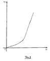
- Variation of the third harmonic flux T3 as a function of the main flux TF can be determined experimentally and is not linear, as shown in figure 1.
- the high frequency rotating field produces a change of the saturation level of the magnetic circuit of the machine which is a function of the position taken during its rotation; in particular, the saturation level will be maximum when such a high frequency field will be aligned and phased with the main field, it will be at the value determined only by the main airgap flux when the high frequency field is in quadrature with the main field, and finally it will be minimum when the high frequency flux is aligned in counter-phase with the main field.
- the zero sequence component of the flux at the air gap TF also includes a high frequency harmonic FOA at a frequency equal to the difference between the frequency of the additional voltage VHF and the frequency of the main rotating magnetic field.
- maximum and minimum points in the waveform of FOA respectively correspond to maximum and minimum values of the saturation level, that, in turn, occur when respectively the high frequency field is aligned in phase and in phase opposition with the main rotating field.
- the high frequency flux is 90° leading the additional high frequency voltage VHF, it is possible to univocally determine the angular position FP of the airgap flux TF, from the known angular position of the voltage VHF, at the time instants in which maximum, minimum and zero points of FOA take place.
- the amplitude of the zero sequence voltage harmonic VOA is strictly proportional to the amplitude of the zero sequence airgap flux component FOA, and related to the amplitude of the airgap flux TF by mean of the function drawn in Fig. 2. Moreover VOA is 90° leading the zero sequence airgap flux component FOA, thus the position FP of the airgap flux TF can be also univocally determined, from the known angular position of the voltage VHF, at the time instants in which maximum, minimum and zero points of VOA take place.
- a high frequency zero sequence component IOA of the stator current is generated, having the same frequency of the zero sequence airgap flux component FOA. Due to the features of the high frequency zero sequence current path, the amplitude of the zero sequence current component IOA is proportional to the amplitude of the zero sequence voltage component VOA. Moreover, a constant phase displacement exists between IOA and VOA, enabling the determination of the angular position FP of the airgap flux TF, from the known angular position of the voltage VHF, at the time instants in which maximum, minimum and zero points of IOA take place.
- the third harmonic phase voltages V31, V32, V33 and the high frequency zero sequence harmonic components can be picked up directly between the terminals of the stator ST and the star centre N of the stator windings, without any significant phase error. Then, the total zero sequence voltage VSM can be obtained by adding the three phase voltages of the machine at any time instant.
- the global zero sequence voltage VSM can be picked up between the star centre N of the stator windings ST1, ST2, ST3 and the central point O of the capacitors C1, C2 of the direct current bus BS, which feeds the inverter PWM with width impulse modulation.
- a voltage proportional to the global zero voltage VSM can be picked up between a fictitious star centre NF, obtained by connecting a star of three equal impedances in any point of the cable connecting the inverter at the machine, and the central point O of the capacitors C1, C2 of the direct current bus BS, which feeds the inverter PWM.
- a further alternative is to measure the total zero sequence current ISM.
- the third harmonic component of the zero sequence voltage VSM which is the output of the voltage transducer TV, or of the zero sequence current ISM, is eliminated by a band-pass filter PB that also eliminates further high frequency harmonics, as those produced by the inverter PWM and by the rotor slots, as well as high frequency noises.
- the amplitude FA of the airgap flux TF is obtained, using a computing device CA, from the amplitude of the voltage VOA, that is the output of the band-pass filter PB, according to the experimental function shown in Fig. 2.
- the angular position FP of the airgap flux TF is obtained, using a computing device CP, from the known angular position of the voltage VHF, by detecting the maximum, minimum and zero points of the voltage VOA.
- the angular position FP of the airgap flux TF can be obtained, using a suitable computing device, by integration of the difference between the known angular speed of the voltage VHF and the measurable angular speed of the zero frequency voltage component VOA.
- a high performance induction motor drive can be experimentally implemented in a simple and inexpensive way, as the one illustrated in the schematic diagram of figure 4, that exploits the method and the system for the measurement of the angular position of the airgap flux, according to the present invention.
- the injection of the set of three high frequency voltages VHF, the measurement of the zero sequence component VSM from the stator voltages V31, V32, V33, the filtering operation of the high frequency harmonics, the measurement of the maximum, minimum and zero points, using the computing device CP, can be carried out utilizing low cost analogue circuits and there are various schemes which can be realised, as the one of figure 4, which represents a non limiting example of embodiment of the system according to the invention. Note that in such a scheme also the block XF is shown, which performs the field oriented control of the motor in a predetermined reference system, as well as the block RC that performs the stator current control.
- the signal VSM obtained at the output of TV is then filtered and amplified in order to achieve a good signal/noise ratio.
- the block CP performs the estimation of the angular position of the airgap flux according to the invention.
- the estimated airgap flux angular position FP is then sent to the block XF performing the field orientation.
- the block XF receives as inputs the reference stator current components ID and IQ, then it makes a transformation from the two phase rotating reference frame synchronous with the flux, to a three phase fixed reference system, in order to generate the stator current reference IR.
- the actual stator current is measured by the current transducer TA, while the notch filter EB is used to eliminate the high frequency components in the current feedback loop.
- the current regulator device RC manages the reference stator voltage VR in order to minimise the error between the reference stator current IR and the feedback signal IF.
- stator reference voltage VR is then added to the high frequency component VHF and, finally, sent to the inverter PWM.
- a low performance induction motor drive can be also experimentally implemented in a simple and inexpensive way, as the one illustrated in the schematic diagram of figure 3, which represents a non limiting example of embodiment of the system according to the invention, that exploits the method and the system for the measurement of the amplitude of the airgap flux object of the present invention.
- CT, RT torque control
- XF field orientation
- TA, EB, RC stator current control
- CP angular position of the airgap flux
- the control of the amplitude of the airgap flux is performed by mean of the flux regulator RF that generates the stator voltage amplitude reference value VS, in order to minimise the error between the flux reference FR and the estimated flux amplitude FA.
- the inverter PWM reference signal VR is generated by the block BO according, for example, to a constant volt/hertz technique.
Landscapes
- Engineering & Computer Science (AREA)
- Power Engineering (AREA)
- Control Of Ac Motors In General (AREA)
- Control Of Multiple Motors (AREA)
- Control Of Electric Motors In General (AREA)
- Steering Control In Accordance With Driving Conditions (AREA)
Abstract
Description
- The present invention relates to The present invention refers to a control method for sensorless drives with induction motors.
- Currently induction motor drives are widely used in electric traction systems and in several industrial applications, such as machine tools, pumps, conveyor belts and others, wherein they are progressively replacing the traditional direct current motor drives, thanks to their improved robustness, reduced maintenance and to the lower production costs.
- According to their dynamic performance, induction motor drives, may be divided into two categories: low performance drives and high performance drives.
- In low performance induction motor drives speed regulators may be open-loop type (constant Volt/Hertz technique) or closed-loop type (slip control technique), while flux and torque control are performed by scalar control approaches, acting only on the amplitude of the electric variables. Such scalar control approaches require the knowledge of the amplitude of the stator flux in order to determine the stator voltage as function of the frequency and the speed.
- In high performance induction motor drives speed and position controllers are of the closed loop type, while flux and torque control are performed by vector control approaches, acting on both the amplitude and the angular position of the rotating vectors representing the electric variables. Among induction motor vector control techniques, field orientation is today the most widely diffused approach. It performs an independent regulation of flux and torque by acting on the stator current components according to a two phase rotating reference frame, synchronous with the rotor flux. Control techniques based on the field orientation principle require the knowledge of both the amplitude and the angular position of the rotor flux.
- The amplitude and the angular position of both the stator flux and the rotor flux can be obtained from the amplitude and the angular position of the airgap flux by adding proper corrective terms depending on the stator current and the induction machine parameters.
- The amplitude and the angular position of the airgap flux could be, in theory, directly measured using Hall effect flux sensors. Such sensors, however, do not provide in practice the required precision; further, their instalment inside the machine is often complex.
- In low performance drives, rather than measuring the amplitude of the airgap flux, an approximated constant value is instead used. In high performance drives, based on the field orientation principle, the amplitude and the position of the rotor flux can be determined directly from measured stator voltages and currents (direct field orientation) or, more commonly, in an indirect way, by means of a mathematical model of the motor (indirect field orientation). This last technique is, by far, the most used, even though it requires an angular position transducer of the machine shaft, with a resolution equal at least to 8 bits, and although the so obtained results are extremely sensitive to rotor resistance variations caused by the temperature.
- Sensitivity to parameter variation and the need to introduce within the drive a relatively expensive position sensor, have initiated the development of alternative techniques, of the "sensorless" type, suitable to determine the amplitude and the angular position of the rotor flux without using a position transducer.
- The most common sensorless control techniques are based on the direct field orientation approach, wherein the amplitude and the angular position of the rotor flux are obtained from the back electromotive force (EMF). Techniques based on such a principle can be easily implemented at a low cost, but they fail at low stator voltage frequencies.
- The lack of a correct estimation of the amplitude and/or the angular position of the airgap flux at low frequency causes strong restrictions to induction motor drives operations at low speed as well as at locked rotor.
- More sophisticated sensorless type control techniques, based on injecting suitable test signals and on measuring the high frequency current harmonics allow to noticeably reduce the minimum motor speed allowed by the control; however also such techniques do not completely solve the problem of torque and flux control at very low or zero speeds.
- On this regard, it has to be noted that the motor control at very low or zero speed is required very frequently and, in particular, it is useful in electric traction applications, in robotics, in many machine tools of the new generation, and, in general, in all those applications where it is required to balance a load at standstill or to bring a shaft back to a given position.
- A method for controlling an induction motor is known from US 5 559 419.
- A purpose of the present invention is therefore to realize a control system for low performance induction motor drives able to overcome the above mentioned disadvantages and, in particular, to define a control system to realise "sensorless type" electrical drive means, based on the constant Volt/Hertz technique, or on the slip control technique, able to properly work at very low speeds or even at zero speed.
- Another purpose of the present invention is to realize a control system for high performance induction motor drives able to overcome the above mentioned disadvantages and, in particular, to define a control system to realise "sensorless type" electrical drive means, based on the direct field orientation approach, able to properly work at very low speeds or even at zero speed.
- Another purpose of the present invention is to define a method for the measurement of the amplitude and/or the angular position of the airgap flux in induction motor drives, able to properly work at any stator voltage frequency and, in particular, at very low and zero frequency.
- Another purpose of the present invention is to indicate a system for the measurement of the amplitude and/or the angular position of the airgap flux, to be used in the realisation of high performance and low performance sensorless induction motor drives.
- A further purpose of the present invention is to define some control schemes for induction motor drives using said method and system of measurement, able to correctly work at very low and zero speed, irrespectively from load changes. Moreover, to indicate some exemplary implementation schemes using conventional circuits and computing devices easy to install and to use, at low costs compared to standard techniques and in consideration of the attained advantages.
- According to the present invention, those purposes are achieved by the method of claim 1.
- Further object, features and advantages of the induction motor drives realised according to the invention, will be better understood from the following detailed description, relative to an example of a preferred and explanatory, non limiting, implementation which refers to the accompaning attached schematic drawings, wherein:
- figure 1 shows the relationships between the third harmonic flux path and the airgap flux of an induction motor;
- figure 2 shows the relationships between the amplitude of the zero sequence stator voltage component generated by the interaction between the main rotating field and a suitable high frequency magnetic field, and the amplitude of the airgap flux.
- figure 3 is a schematic diagram of a first exemplary sensorless control system for low performance induction motor drives, where the amplitude of the airgap flux is estimated according to the present invention.
- figure 4 is a schematic diagram of a first exemplary sensorless control system for high performance induction motor drives, where the angular position of the airgap flux is estimated according to the present invention.
- figure 5 is a schematic diagram of a first exemplary sensorless control system for high performance induction motor drives, where the amplitude and the angular position of the airgap flux are estimated according to the present invention.
- With reference to the above mentioned figures, T3 indicates the third harmonic component of the airgap flux TF, BS indicates the feeding bus of the inverter PWM, ST1, ST2, ST3 indicate the windings of the three phases of the stator ST of the electric machine, TV indicates a voltage transducer, TA a current transducer, PB indicates a band-pass filter, EB indicates a notch filter, CA indicates an electronic device, or a software procedure, to evaluate the amplitude FA of the airgap flux TF, CP indicates an electronic device ,or a software procedure, to evaluate the angular position FP of the airgap flux TF, RC indicates a stator current control system, while B0 indicates an electronic device, or a software procedure, to perform the machine control according to the constant Volt/Hertz technique, and XF indicates an electronic device, or a software procedure, to perform the machine control according to the field orientation principle.
- Induction motors, in normal operating conditions and rated flux, work in the bend area of the curve B-H of the ferromagnetic material which represents the core; further, the ferromagnetic core of the machine is more saturated along the flux direction.
- As a consequence, the saturation causes a local anisotropy of the induction machine which, by itself, has a non salient magnetic structure.
- The space distribution of the airgap flux TF is not perfectly sinusoidal, due to saturation, with a harmonic content characterised by the presence of odd and zero sequence harmonics, but strongly influenced by the third harmonic component T3. The third harmonic T3 of the flux at the air gap TF induces, in the three phases F1, F2, F3 of the stator windings ST1, ST2, ST3, three third harmonic voltages V31, V32, V33, which are in phase among them, and form a zero sequence three phase voltage.
- Variation of the third harmonic flux T3 as a function of the main flux TF can be determined experimentally and is not linear, as shown in figure 1.
- If a direct or an inverse set of high frequency three-phase voltages VHF is added to the stator three-phase voltage, a high frequency rotating magnetic field will be produced, which interacts with the main magnetic field.
- The high frequency rotating field produces a change of the saturation level of the magnetic circuit of the machine which is a function of the position taken during its rotation; in particular, the saturation level will be maximum when such a high frequency field will be aligned and phased with the main field, it will be at the value determined only by the main airgap flux when the high frequency field is in quadrature with the main field, and finally it will be minimum when the high frequency flux is aligned in counter-phase with the main field.
- Because of the periodic change of saturation, due to interaction between the main field and the high frequency field, the zero sequence component of the flux at the air gap TF, usually characterised by the presence of the third harmonic component T3, also includes a high frequency harmonic FOA at a frequency equal to the difference between the frequency of the additional voltage VHF and the frequency of the main rotating magnetic field. Moreover, maximum and minimum points in the waveform of FOA, respectively correspond to maximum and minimum values of the saturation level, that, in turn, occur when respectively the high frequency field is aligned in phase and in phase opposition with the main rotating field. Since the high frequency flux is 90° leading the additional high frequency voltage VHF, it is possible to univocally determine the angular position FP of the airgap flux TF, from the known angular position of the voltage VHF, at the time instants in which maximum, minimum and zero points of FOA take place.
- The fact that the relation between the airgap flux and its third harmonic component is not linear, as it is shown in Fig.1, provides to enhance the phenomenon, thus making significant the high frequency harmonic of the flux and able to induce a zero sequence high frequency voltage component VOA, having the same frequency of FOA, superimposed to the third harmonic voltages V31, V32, V33.
- The amplitude of the zero sequence voltage harmonic VOA is strictly proportional to the amplitude of the zero sequence airgap flux component FOA, and related to the amplitude of the airgap flux TF by mean of the function drawn in Fig. 2. Moreover VOA is 90° leading the zero sequence airgap flux component FOA, thus the position FP of the airgap flux TF can be also univocally determined, from the known angular position of the voltage VHF, at the time instants in which maximum, minimum and zero points of VOA take place.
- If the zero sequence path is closed through the ground, then also a high frequency zero sequence component IOA of the stator current is generated, having the same frequency of the zero sequence airgap flux component FOA. Due to the features of the high frequency zero sequence current path, the amplitude of the zero sequence current component IOA is proportional to the amplitude of the zero sequence voltage component VOA. Moreover, a constant phase displacement exists between IOA and VOA, enabling the determination of the angular position FP of the airgap flux TF, from the known angular position of the voltage VHF, at the time instants in which maximum, minimum and zero points of IOA take place.
- These results can also be obtained by introducing a direct or inverse symmetric set of three high frequency currents or by introducing a high frequency voltage or current component along the direction of the airgap flux TF.
- The third harmonic phase voltages V31, V32, V33 and the high frequency zero sequence harmonic components can be picked up directly between the terminals of the stator ST and the star centre N of the stator windings, without any significant phase error. Then, the total zero sequence voltage VSM can be obtained by adding the three phase voltages of the machine at any time instant.
- Alternatively, the global zero sequence voltage VSM can be picked up between the star centre N of the stator windings ST1, ST2, ST3 and the central point O of the capacitors C1, C2 of the direct current bus BS, which feeds the inverter PWM with width impulse modulation.
- If the star centre N of the stator windings ST1, ST2, ST3 is not accessible, then a voltage proportional to the global zero voltage VSM can be picked up between a fictitious star centre NF, obtained by connecting a star of three equal impedances in any point of the cable connecting the inverter at the machine, and the central point O of the capacitors C1, C2 of the direct current bus BS, which feeds the inverter PWM.
- A further alternative is to measure the total zero sequence current ISM.
- The third harmonic component of the zero sequence voltage VSM, which is the output of the voltage transducer TV, or of the zero sequence current ISM, is eliminated by a band-pass filter PB that also eliminates further high frequency harmonics, as those produced by the inverter PWM and by the rotor slots, as well as high frequency noises.
- The amplitude FA of the airgap flux TF is obtained, using a computing device CA, from the amplitude of the voltage VOA, that is the output of the band-pass filter PB, according to the experimental function shown in Fig. 2.
- The angular position FP of the airgap flux TF is obtained, using a computing device CP, from the known angular position of the voltage VHF, by detecting the maximum, minimum and zero points of the voltage VOA.
- Alternatively, the angular position FP of the airgap flux TF can be obtained, using a suitable computing device, by integration of the difference between the known angular speed of the voltage VHF and the measurable angular speed of the zero frequency voltage component VOA.
- A high performance induction motor drive, according to the present invention, can be experimentally implemented in a simple and inexpensive way, as the one illustrated in the schematic diagram of figure 4, that exploits the method and the system for the measurement of the angular position of the airgap flux, according to the present invention.
- The injection of the set of three high frequency voltages VHF, the measurement of the zero sequence component VSM from the stator voltages V31, V32, V33, the filtering operation of the high frequency harmonics, the measurement of the maximum, minimum and zero points, using the computing device CP, can be carried out utilizing low cost analogue circuits and there are various schemes which can be realised, as the one of figure 4, which represents a non limiting example of embodiment of the system according to the invention. Note that in such a scheme also the block XF is shown, which performs the field oriented control of the motor in a predetermined reference system, as well as the block RC that performs the stator current control.
- In particular, the voltage VOA is obtained by measuring, through the transducer TV, the voltage VS1 between the star centre N of the stator windings ST1, ST2, ST3 and the central point O of the capacitors C1, C2 of the direct current bus BS of the inverter PWM.
- The signal VSM obtained at the output of TV is then filtered and amplified in order to achieve a good signal/noise ratio. The block CP performs the estimation of the angular position of the airgap flux according to the invention.
- The estimated airgap flux angular position FP is then sent to the block XF performing the field orientation. The block XF receives as inputs the reference stator current components ID and IQ, then it makes a transformation from the two phase rotating reference frame synchronous with the flux, to a three phase fixed reference system, in order to generate the stator current reference IR.
- The actual stator current is measured by the current transducer TA, while the notch filter EB is used to eliminate the high frequency components in the current feedback loop.
- The current regulator device RC manages the reference stator voltage VR in order to minimise the error between the reference stator current IR and the feedback signal IF.
- The stator reference voltage VR is then added to the high frequency component VHF and, finally, sent to the inverter PWM.
- From the given description, the system characteristics and the method of control for an induction motor drive, which are the object of the present invention, are clearly defined, as well as the advantages.
- An alternative scheme for high performance induction motor drives, according to the present invention, can be experimentally implemented in a simple and inexpensive way, as the one illustrated in the schematic diagram of figure 5, which represents a non limiting example of embodiment of the system according to the invention, that exploits the method and the system for the measurement of the amplitude and the angular position of the airgap flux object of the present invention.
- If compared with the scheme of Fig. 4, in the scheme of Fig. 5 it is evident the presence of the block CA that determines the amplitude FA of the airgap flux vector TF from the amplitude of the voltage VOA, according to the function shown in Fig. 2. A further difference consists in the presence of the block CT that estimates the electromagnetic torque TM according to the actual values of the stator current IF, as well as the amplitude FA and the angular position FP of the airgap flux. The knowledge of the actual values of the motor torque and flux allows to perform a closed loop control of such variables, by means of the torque regulator RT and the flux regulator RF. Such blocks generates the reference values ID and IQ of the stator current components according to a rotating reference frame synchronous with the flux, that in the scheme of Fig. 4 were imposed by an external device.
- A low performance induction motor drive, according to the present invention, can be also experimentally implemented in a simple and inexpensive way, as the one illustrated in the schematic diagram of figure 3, which represents a non limiting example of embodiment of the system according to the invention, that exploits the method and the system for the measurement of the amplitude of the airgap flux object of the present invention.
- If compared with the schemes of Fig. 4 and Fig. 5, in the scheme of Fig. 3 are not included the blocks that perform the torque control (CT, RT), the field orientation (XF), the stator current control (TA, EB, RC) and the estimation of the angular position of the airgap flux (CP). The control of the amplitude of the airgap flux is performed by mean of the flux regulator RF that generates the stator voltage amplitude reference value VS, in order to minimise the error between the flux reference FR and the estimated flux amplitude FA. Finally the inverter PWM reference signal VR is generated by the block BO according, for example, to a constant volt/hertz technique.
Claims (9)
- A control method for electric drive means with induction motors, wherein said induction motor includes a stator (ST) with a plurality of stator windings (ST1, ST2, ST3) thereon, a rotor mounted for rotation within the stator (ST) and a ferromagnetic core, said method comprising the steps of operating said motor with a main magnetic field in condition of magnetic saturation, with an air-gap flux (TF) having a space distribution with a harmonic content including at least one harmonic component (T3), which induces, in said stator windings (ST1, ST2, ST3), harmonic phase voltages (V31, V32, V33) forming a zero sequence stator voltage (VSM) or current (ISM), superposing to said main rotating magnetic field a high frequency rotating magnetic field generated by adding a set of direct or inverse symmetric high frequency voltages (VHF) or currents (IHF) to standard stator phase voltages of the motor, thereby causing variation of the saturation level of the ferromagnetic core of said induction motor and generating a high frequency zero-phase sequence component (T3) of the air-gap flux (TF), which induces, in said stator windings (ST1, ST2, ST3), high frequency zero sequence voltage (VSM) or current (ISM) harmonic components, said high frequency zero sequence voltage (VSM) or current (ISM) components being functions of the relative positions taken by said additional set of high frequency voltages (VHF) or currents (IHF) and said main rotating magnetic field (MRF), so that when said additional set of voltages (VHF) or currents (IHF) is in phase with the main rotating magnetic field (MRF), a maximum of the saturation level of the ferromagnetic core of the motor takes place, causing the occurrence of a local minimum on said high frequency zero-phase sequence component (T3) of the air-gap flux (TF), that is reflected as a local maximum on said induced high frequency zero-phase sequence stator voltage (VSM) or current (ISM) components; the method being further characterized in:detecting the zero sequence voltage or the zero voltage current,measuring the angular position and/or the amplitude of the air gap main magnetic flux from the high frequency zero sequence voltage or current harmonic components.
- A control method as claimed in claim 1, characterised in that it further comprises the step of filtering and amplifying said zero-phase sequence stator voltage (VSM) with means for filtering and amplifying, so as to obtain a ratio between signal and noise, and using a notch filter (EB), which is connected to a first signal processing and control block (RC) to eliminate undesirable high frequency components from a feedback loop (FA, FP) of current signals.
- A control method as claimed in claim 2, characterised in that said feedback loop (FA, FP) comprises at least one control device (RF) of said current signals, which sends a reference signal (VS) to a second processing and control block (BO), so as to generate a reference value (VR), with respect to a fixed axis system, and an electronic device of an inverter type (PWM), which receives said reference value (VR) added together with said set of high frequency voltages (VHF).
- A control method as claimed in claim 3, characterised in the step of adding said set of high frequency voltages (VHF) to a voltage reference signal (VR) or to an output of said current control device (RF).
- A control method as claimed in claim 1, characterised by comprising a step of measuring the amplitude of a component (VOA) of said high frequency zero-phase sequence stator voltage (VSM) having a frequency equal to the difference between the frequency of said additional magnetic field, generated by said additional set of high frequency voltages (VHF), and the frequency of said main rotating magnetic field (MRF) and a step of determining the amplitude of an air-gap flux component (FOA) from the amplitude of said component (VOA) of the high frequency zero-phase sequence stator voltage (VSM).
- A control method as claimed in claim 5, characterised in that the angular position of said air-gap flux (TF) is determined by integrating the difference between the angular frequency of said additional set of high frequency voltages (VHF) and said zero-phase sequence stator voltage (VSM) having a frequency equal to the difference between the frequency of said additional 1 magnetic field and the frequency of said main rotating magnetic field.
- A control method as claimed in claim 5, characterised in that the angular position of said air gap flux (TF) is determined by detecting the angular position of said additional set of high frequency voltages (VHF) in the time instants in which maximum, minimum and zero points occur in said zero-phase sequence stator voltage (VSM) having a frequency equal to the difference between the frequency of said additional magnetic field generated by said additional set of high frequency voltages (VHF) and the frequency of said main rotating magnetic field.
- A control method as claimed in claim 5, characterised in that a total zero-phase sequence stator voltage (VSM), including a third harmonic voltage component and high frequency harmonic components, is obtained as an arithmetical mean of said harmonic phase voltages (V31, V32, V33), said total zero-phase sequence stator voltage (VSM) being obtained by measuring a voltage between a star centre (N) of stator windings (ST1, ST2, ST3) and a central point (O) positioned between two capacitors (C1, C2) connected along a direct current electric line (BS), which feeds an electronic device of the inverter type (PWM).
- A control method as claimed in claim 8, characterised in that a total zero-phase sequence stator current (ISM) is directly determined through suitable sensors or indirectly determined through the measure of a zero-phase sequence voltage drop in any of the points of a connection line between said electronic device of the inverter type (PWM) and the electric motor, said voltage drop being measured by determining the voltage taken between a star centre (NF), obtained by connecting a three impedance star through a shunt to the supply conductors of the motor, and a central point (O) positioned between two capacitors (C1, C2) connected along a direct current electric line (DC) which feeds said electronic device of the inverter type (PWM).
Priority Applications (1)
| Application Number | Priority Date | Filing Date | Title |
|---|---|---|---|
| DK00115629T DK1073193T3 (en) | 1999-07-29 | 2000-07-20 | Method for controlling a sensorless induction motor |
Applications Claiming Priority (4)
| Application Number | Priority Date | Filing Date | Title |
|---|---|---|---|
| ITTO990669 | 1999-07-29 | ||
| IT1999TO000669A IT1310649B1 (en) | 1999-07-29 | 1999-07-29 | CONTROL SYSTEM AND METHOD FOR ELECTRIC DRIVES WITH ASYNCHRONOUS MOTOR. |
| US501056 | 2000-02-09 | ||
| US09/501,056 US6559618B1 (en) | 1999-07-29 | 2000-02-09 | System and method of control for sensorless induction motor drives |
Publications (3)
| Publication Number | Publication Date |
|---|---|
| EP1073193A2 EP1073193A2 (en) | 2001-01-31 |
| EP1073193A3 EP1073193A3 (en) | 2001-05-30 |
| EP1073193B1 true EP1073193B1 (en) | 2005-04-06 |
Family
ID=11418006
Family Applications (1)
| Application Number | Title | Priority Date | Filing Date |
|---|---|---|---|
| EP00115629A Expired - Lifetime EP1073193B1 (en) | 1999-07-29 | 2000-07-20 | Method of control for sensorless induction motor drives |
Country Status (7)
| Country | Link |
|---|---|
| US (1) | US6559618B1 (en) |
| EP (1) | EP1073193B1 (en) |
| AT (1) | ATE292856T1 (en) |
| DE (1) | DE60019208T8 (en) |
| DK (1) | DK1073193T3 (en) |
| ES (1) | ES2239973T3 (en) |
| IT (1) | IT1310649B1 (en) |
Families Citing this family (3)
| Publication number | Priority date | Publication date | Assignee | Title |
|---|---|---|---|---|
| US7778053B2 (en) * | 2006-02-13 | 2010-08-17 | American Superconductor Corp. | Power system having a voltage regulator with a notch filter |
| US10738784B2 (en) * | 2017-09-14 | 2020-08-11 | Unico, Llc | Power-loss ridethrough system and method |
| CN113965125B (en) * | 2021-10-12 | 2024-01-16 | 上海飒智智能科技有限公司 | Intelligent mobile robot hub motor servo driver parallel control method |
Family Cites Families (11)
| Publication number | Priority date | Publication date | Assignee | Title |
|---|---|---|---|---|
| US4011489A (en) * | 1974-11-20 | 1977-03-08 | General Electric Company | Apparatus for regulating magnetic flux in an AC motor |
| US4445080A (en) | 1981-11-25 | 1984-04-24 | The Charles Stark Draper Laboratory, Inc. | System for indirectly sensing flux in an induction motor |
| US5254918A (en) | 1990-06-08 | 1993-10-19 | Victor Company Of Japan, Ltd. | Detection of position of rotor in brushless dc motor |
| US5272429A (en) * | 1990-10-01 | 1993-12-21 | Wisconsin Alumni Research Foundation | Air gap flux measurement using stator third harmonic voltage and uses |
| US5334923A (en) * | 1990-10-01 | 1994-08-02 | Wisconsin Alumni Research Foundation | Motor torque control method and apparatus |
| EP0579694B1 (en) | 1991-04-11 | 1995-12-13 | Elin Energieanwendung Gesellschaft M.B.H. | Process and circuits for determining machine-related electromagnetic and mechanical state variables on electrodynamic induction machines supplied via converters |
| TW291623B (en) | 1993-04-28 | 1996-11-21 | Hitachi Ltd | |
| US5585709A (en) * | 1993-12-22 | 1996-12-17 | Wisconsin Alumni Research Foundation | Method and apparatus for transducerless position and velocity estimation in drives for AC machines |
| US5559419A (en) | 1993-12-22 | 1996-09-24 | Wisconsin Alumni Research Foundation | Method and apparatus for transducerless flux estimation in drives for induction machines |
| KR100264916B1 (en) * | 1997-08-05 | 2000-09-01 | 설승기 | Sensorless field orientation contorl of induction machine using high frequency injection method |
| US6137258A (en) * | 1998-10-26 | 2000-10-24 | General Electric Company | System for speed-sensorless control of an induction machine |
-
1999
- 1999-07-29 IT IT1999TO000669A patent/IT1310649B1/en active
-
2000
- 2000-02-09 US US09/501,056 patent/US6559618B1/en not_active Expired - Fee Related
- 2000-07-20 AT AT00115629T patent/ATE292856T1/en not_active IP Right Cessation
- 2000-07-20 ES ES00115629T patent/ES2239973T3/en not_active Expired - Lifetime
- 2000-07-20 EP EP00115629A patent/EP1073193B1/en not_active Expired - Lifetime
- 2000-07-20 DE DE60019208T patent/DE60019208T8/en not_active Expired - Fee Related
- 2000-07-20 DK DK00115629T patent/DK1073193T3/en active
Also Published As
| Publication number | Publication date |
|---|---|
| DE60019208D1 (en) | 2005-05-12 |
| ES2239973T3 (en) | 2005-10-16 |
| EP1073193A3 (en) | 2001-05-30 |
| US6559618B1 (en) | 2003-05-06 |
| IT1310649B1 (en) | 2002-02-19 |
| DE60019208T8 (en) | 2006-04-27 |
| DK1073193T3 (en) | 2005-08-08 |
| EP1073193A2 (en) | 2001-01-31 |
| ATE292856T1 (en) | 2005-04-15 |
| ITTO990669A0 (en) | 1999-07-29 |
| ITTO990669A1 (en) | 2001-01-29 |
| DE60019208T2 (en) | 2006-02-09 |
Similar Documents
| Publication | Publication Date | Title |
|---|---|---|
| Wang et al. | Rotor position estimation for permanent magnet synchronous motor using saliency-tracking self-sensing method | |
| EP1998435B1 (en) | Method and system for estimating rotor angular position and rotor angular velocity at low speeds or standstill | |
| Consoli et al. | A new zero-frequency flux-position detection approach for direct-field-oriented-control drives | |
| EP1876702B1 (en) | Motor control device | |
| Degner et al. | Using multiple saliencies for the estimation of flux, position, and velocity in AC machines | |
| EP2061147B1 (en) | Initial rotor position detection and start-up system for a dynamoelectric machine | |
| US8330403B2 (en) | Method for determining the position of the flux vector of a motor | |
| US7180262B2 (en) | Control system and method for electric drives with a.c. motors | |
| KR100264916B1 (en) | Sensorless field orientation contorl of induction machine using high frequency injection method | |
| KR101046802B1 (en) | Control device of AC rotor and electric constant measurement method of AC rotor using this controller | |
| US20090200974A1 (en) | Sensorless control apparatus of synchronous machine | |
| JP2008220096A (en) | Sensorless controller of synchronous electric motor | |
| Saitoh et al. | Adaptive signal injection method combined with EEMF-based position sensorless control of IPMSM drives | |
| JP5120621B2 (en) | Control device for permanent magnet type synchronous motor | |
| Brandstetter et al. | Sensorless control of permanent magnet synchronous motor using voltage signal injection | |
| US9331618B2 (en) | Magnetic pole position detector for synchronous motor | |
| JP4154149B2 (en) | Vector control inverter device | |
| JP5396741B2 (en) | Control device for permanent magnet type synchronous motor | |
| Hammel et al. | Operating point dependent anisotropies and assessment for position-sensorless control | |
| EP1073193B1 (en) | Method of control for sensorless induction motor drives | |
| CN112019114A (en) | Method for measuring zero offset angle of motor control system | |
| CN111512539A (en) | Method for determining the rotor position of an induction machine without a rotation sensor and device for regulating an alternating current machine without a rotation sensor | |
| JP2002272195A (en) | Synchronous motor control device | |
| Jing et al. | Optimization of speed loop control technology for permanent magnet synchronous motor servo system | |
| JP3405115B2 (en) | Measurement method of electric angle deviation of electric motor |
Legal Events
| Date | Code | Title | Description |
|---|---|---|---|
| PUAI | Public reference made under article 153(3) epc to a published international application that has entered the european phase |
Free format text: ORIGINAL CODE: 0009012 |
|
| AK | Designated contracting states |
Kind code of ref document: A2 Designated state(s): AT BE CH CY DE DK ES FI FR GB GR IE IT LI LU MC NL PT SE |
|
| AX | Request for extension of the european patent |
Free format text: AL;LT;LV;MK;RO;SI |
|
| PUAL | Search report despatched |
Free format text: ORIGINAL CODE: 0009013 |
|
| AK | Designated contracting states |
Kind code of ref document: A3 Designated state(s): AT BE CH CY DE DK ES FI FR GB GR IE IT LI LU MC NL PT SE |
|
| AX | Request for extension of the european patent |
Free format text: AL;LT;LV;MK;RO;SI |
|
| 17P | Request for examination filed |
Effective date: 20010821 |
|
| 17Q | First examination report despatched |
Effective date: 20011219 |
|
| AKX | Designation fees paid |
Free format text: AT BE CH CY DE DK ES FI FR GB GR IE IT LI LU MC NL PT SE |
|
| AXX | Extension fees paid |
Free format text: AL PAYMENT 20010821;LT PAYMENT 20010821;LV PAYMENT 20010821;RO PAYMENT 20010821;SI PAYMENT 20010821 |
|
| GRAP | Despatch of communication of intention to grant a patent |
Free format text: ORIGINAL CODE: EPIDOSNIGR1 |
|
| RTI1 | Title (correction) |
Free format text: METHOD OF CONTROL FOR SENSORLESS INDUCTION MOTOR DRIVES |
|
| GRAS | Grant fee paid |
Free format text: ORIGINAL CODE: EPIDOSNIGR3 |
|
| GRAA | (expected) grant |
Free format text: ORIGINAL CODE: 0009210 |
|
| AK | Designated contracting states |
Kind code of ref document: B1 Designated state(s): AT BE CH CY DE DK ES FI FR GB GR IE IT LI LU MC NL PT SE |
|
| AX | Request for extension of the european patent |
Extension state: AL LT LV RO SI |
|
| PG25 | Lapsed in a contracting state [announced via postgrant information from national office to epo] |
Ref country code: AT Free format text: LAPSE BECAUSE OF FAILURE TO SUBMIT A TRANSLATION OF THE DESCRIPTION OR TO PAY THE FEE WITHIN THE PRESCRIBED TIME-LIMIT Effective date: 20050406 Ref country code: FI Free format text: LAPSE BECAUSE OF FAILURE TO SUBMIT A TRANSLATION OF THE DESCRIPTION OR TO PAY THE FEE WITHIN THE PRESCRIBED TIME-LIMIT Effective date: 20050406 Ref country code: LI Free format text: LAPSE BECAUSE OF FAILURE TO SUBMIT A TRANSLATION OF THE DESCRIPTION OR TO PAY THE FEE WITHIN THE PRESCRIBED TIME-LIMIT Effective date: 20050406 Ref country code: BE Free format text: LAPSE BECAUSE OF FAILURE TO SUBMIT A TRANSLATION OF THE DESCRIPTION OR TO PAY THE FEE WITHIN THE PRESCRIBED TIME-LIMIT Effective date: 20050406 Ref country code: NL Free format text: LAPSE BECAUSE OF FAILURE TO SUBMIT A TRANSLATION OF THE DESCRIPTION OR TO PAY THE FEE WITHIN THE PRESCRIBED TIME-LIMIT Effective date: 20050406 Ref country code: CH Free format text: LAPSE BECAUSE OF FAILURE TO SUBMIT A TRANSLATION OF THE DESCRIPTION OR TO PAY THE FEE WITHIN THE PRESCRIBED TIME-LIMIT Effective date: 20050406 |
|
| REG | Reference to a national code |
Ref country code: GB Ref legal event code: FG4D |
|
| REG | Reference to a national code |
Ref country code: CH Ref legal event code: EP |
|
| REG | Reference to a national code |
Ref country code: IE Ref legal event code: FG4D |
|
| REF | Corresponds to: |
Ref document number: 60019208 Country of ref document: DE Date of ref document: 20050512 Kind code of ref document: P |
|
| PG25 | Lapsed in a contracting state [announced via postgrant information from national office to epo] |
Ref country code: SE Free format text: LAPSE BECAUSE OF FAILURE TO SUBMIT A TRANSLATION OF THE DESCRIPTION OR TO PAY THE FEE WITHIN THE PRESCRIBED TIME-LIMIT Effective date: 20050706 Ref country code: GR Free format text: LAPSE BECAUSE OF FAILURE TO SUBMIT A TRANSLATION OF THE DESCRIPTION OR TO PAY THE FEE WITHIN THE PRESCRIBED TIME-LIMIT Effective date: 20050706 |
|
| PG25 | Lapsed in a contracting state [announced via postgrant information from national office to epo] |
Ref country code: LU Free format text: LAPSE BECAUSE OF NON-PAYMENT OF DUE FEES Effective date: 20050720 Ref country code: CY Free format text: LAPSE BECAUSE OF FAILURE TO SUBMIT A TRANSLATION OF THE DESCRIPTION OR TO PAY THE FEE WITHIN THE PRESCRIBED TIME-LIMIT Effective date: 20050720 Ref country code: IE Free format text: LAPSE BECAUSE OF NON-PAYMENT OF DUE FEES Effective date: 20050720 |
|
| PG25 | Lapsed in a contracting state [announced via postgrant information from national office to epo] |
Ref country code: MC Free format text: LAPSE BECAUSE OF NON-PAYMENT OF DUE FEES Effective date: 20050731 |
|
| REG | Reference to a national code |
Ref country code: DK Ref legal event code: T3 |
|
| PG25 | Lapsed in a contracting state [announced via postgrant information from national office to epo] |
Ref country code: PT Free format text: LAPSE BECAUSE OF FAILURE TO SUBMIT A TRANSLATION OF THE DESCRIPTION OR TO PAY THE FEE WITHIN THE PRESCRIBED TIME-LIMIT Effective date: 20050908 |
|
| LTIE | Lt: invalidation of european patent or patent extension |
Effective date: 20050406 |
|
| NLV1 | Nl: lapsed or annulled due to failure to fulfill the requirements of art. 29p and 29m of the patents act | ||
| REG | Reference to a national code |
Ref country code: CH Ref legal event code: PL |
|
| REG | Reference to a national code |
Ref country code: ES Ref legal event code: FG2A Ref document number: 2239973 Country of ref document: ES Kind code of ref document: T3 |
|
| PLBE | No opposition filed within time limit |
Free format text: ORIGINAL CODE: 0009261 |
|
| STAA | Information on the status of an ep patent application or granted ep patent |
Free format text: STATUS: NO OPPOSITION FILED WITHIN TIME LIMIT |
|
| ET | Fr: translation filed | ||
| 26N | No opposition filed |
Effective date: 20060110 |
|
| REG | Reference to a national code |
Ref country code: IE Ref legal event code: MM4A |
|
| PGFP | Annual fee paid to national office [announced via postgrant information from national office to epo] |
Ref country code: DK Payment date: 20090714 Year of fee payment: 10 Ref country code: ES Payment date: 20090812 Year of fee payment: 10 Ref country code: FR Payment date: 20090710 Year of fee payment: 10 |
|
| PGFP | Annual fee paid to national office [announced via postgrant information from national office to epo] |
Ref country code: GB Payment date: 20090715 Year of fee payment: 10 Ref country code: DE Payment date: 20090716 Year of fee payment: 10 |
|
| GBPC | Gb: european patent ceased through non-payment of renewal fee |
Effective date: 20100720 |
|
| PG25 | Lapsed in a contracting state [announced via postgrant information from national office to epo] |
Ref country code: IT Free format text: LAPSE BECAUSE OF NON-PAYMENT OF DUE FEES Effective date: 20090720 |
|
| REG | Reference to a national code |
Ref country code: FR Ref legal event code: ST Effective date: 20110331 |
|
| PG25 | Lapsed in a contracting state [announced via postgrant information from national office to epo] |
Ref country code: DE Free format text: LAPSE BECAUSE OF NON-PAYMENT OF DUE FEES Effective date: 20110201 |
|
| REG | Reference to a national code |
Ref country code: DE Ref legal event code: R119 Ref document number: 60019208 Country of ref document: DE Effective date: 20110201 |
|
| PG25 | Lapsed in a contracting state [announced via postgrant information from national office to epo] |
Ref country code: FR Free format text: LAPSE BECAUSE OF NON-PAYMENT OF DUE FEES Effective date: 20100802 |
|
| PG25 | Lapsed in a contracting state [announced via postgrant information from national office to epo] |
Ref country code: GB Free format text: LAPSE BECAUSE OF NON-PAYMENT OF DUE FEES Effective date: 20100720 |
|
| PGFP | Annual fee paid to national office [announced via postgrant information from national office to epo] |
Ref country code: IT Payment date: 20090717 Year of fee payment: 10 |
|
| PGRI | Patent reinstated in contracting state [announced from national office to epo] |
Ref country code: IT Effective date: 20110616 |
|
| REG | Reference to a national code |
Ref country code: ES Ref legal event code: FD2A Effective date: 20110818 |
|
| REG | Reference to a national code |
Ref country code: DK Ref legal event code: EBP |
|
| PG25 | Lapsed in a contracting state [announced via postgrant information from national office to epo] |
Ref country code: ES Free format text: LAPSE BECAUSE OF NON-PAYMENT OF DUE FEES Effective date: 20100721 |
|
| PG25 | Lapsed in a contracting state [announced via postgrant information from national office to epo] |
Ref country code: DK Free format text: LAPSE BECAUSE OF NON-PAYMENT OF DUE FEES Effective date: 20100802 |
|
| PGRI | Patent reinstated in contracting state [announced from national office to epo] |
Ref country code: IT Effective date: 20110616 |