EP0302679A2 - Circuit and method for paralleling AC electrical power systems - Google Patents
Circuit and method for paralleling AC electrical power systems Download PDFInfo
- Publication number
- EP0302679A2 EP0302679A2 EP88307057A EP88307057A EP0302679A2 EP 0302679 A2 EP0302679 A2 EP 0302679A2 EP 88307057 A EP88307057 A EP 88307057A EP 88307057 A EP88307057 A EP 88307057A EP 0302679 A2 EP0302679 A2 EP 0302679A2
- Authority
- EP
- European Patent Office
- Prior art keywords
- load current
- current signal
- signal
- controllable
- voltage power
- Prior art date
- Legal status (The legal status is an assumption and is not a legal conclusion. Google has not performed a legal analysis and makes no representation as to the accuracy of the status listed.)
- Granted
Links
Images
Classifications
-
- H—ELECTRICITY
- H02—GENERATION; CONVERSION OR DISTRIBUTION OF ELECTRIC POWER
- H02J—CIRCUIT ARRANGEMENTS OR SYSTEMS FOR SUPPLYING OR DISTRIBUTING ELECTRIC POWER; SYSTEMS FOR STORING ELECTRIC ENERGY
- H02J3/00—Circuit arrangements for ac mains or ac distribution networks
- H02J3/38—Arrangements for parallely feeding a single network by two or more generators, converters or transformers
- H02J3/46—Controlling of the sharing of output between the generators, converters, or transformers
- H02J3/466—Scheduling the operation of the generators, e.g. connecting or disconnecting generators to meet a given demand
-
- H—ELECTRICITY
- H02—GENERATION; CONVERSION OR DISTRIBUTION OF ELECTRIC POWER
- H02J—CIRCUIT ARRANGEMENTS OR SYSTEMS FOR SUPPLYING OR DISTRIBUTING ELECTRIC POWER; SYSTEMS FOR STORING ELECTRIC ENERGY
- H02J3/00—Circuit arrangements for ac mains or ac distribution networks
- H02J3/38—Arrangements for parallely feeding a single network by two or more generators, converters or transformers
- H02J3/381—Dispersed generators
Definitions
- This invention relates to control circuits and methods for paralleling AC electrical power systems and, more particularly, to such circuits and methods which are applicable to parallel AC power systems having channels with different power ratings.
- AC electric power systems are generally connected in parallel to increase total system rating, or in certain cases such as airborne power systems, to increase reliability.
- Typical aircraft AC electrical power systems include two or more identical power channels. These channels may include a constant speed generator with a constant speed drive (CSD) for frequency control, or a variable speed generator with a constant frequency electronic inverter (VSCF).
- CSD constant speed drive
- VSCF constant frequency electronic inverter
- the total system load be divided equally among the paralleled generators. Load division among AC generators is accomplished by controlling, in a closed loop manner, individual generator voltages and phase angles.
- Controls for paralleling AC systems have been developed for paralleled AC electrical systems. These controls use current transformer loops to sense difference currents between channels. Frequency and voltage controls then drive the difference currents to zero. This type of control system will also work between channels of different power rating if appropriate current transformer ratios are chosen.
- Advanced electrical AC power systems will require that the generating channels have a programmable power rating. Programmability will be needed to accommodate degraded power sources caused by failed rotating rectifiers in brushless AC generators, reduced cooling capacity, damaged fuel cells, etc.
- An object of this invention is to provide a circuit and method for paralleling channels of an AC electric power system wherein individual channels have different and/or variable power ratings.
- Control circuits which perform the method of this invention produce a pair of load current signals which are representative of the load current delivered by two channels of a parallel source electric power system. At least one of these load current signals is scaled by a factor representative of the power rating of one of the power system channels. The scaled load current signal and the other load current signal are combined to produce a feedback signal which is used to modify the operation of one of the paralleled power sources such that the ratio of the load currents delivered by the paralleled power sources is proportional to the scaling factor.
- the scaling factor may be varied in accordance with the power rating of one of the individual power sources. It may also be controlled in order to reduce system transients during application or removal of one of the power sources from the system.
- the load current signals may be produced by current transformers and scaling can be accomplished by multiplying or dividing one of the load current signals by a digital or analog technique.
- the scaled load current signal and the other load current signal can be easily combined by applying them to opposite ends of a resistive branch circuit.
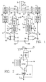
- Figure 1 is a schematic diagram, partially in block diagram form, of a parallel AC electric power system having a control circuit constructed in accordance with the present invention.
- the system contains first and second power sources 10 and 12, which may be variable frequency, variable voltage power sources such as electronic inverters.
- the first power source 10 produces a three phase AC output on lines 14, 16 and 18.
- the second power source 12 produces a three phase output on lines 20, 22 and 24.
- a plurality of power bus conductors 26, 28 and 30 can be connected to the individual phase conductors of the first and second power sources by way of contacts K1, K2, K3, K4, K5 and K6.
- a burden circuit 34 including resistor R1 and capacitor C1 is connected across the current transformer 32 to produce a voltage signal between lines 36 and 38 which is proportional to current flowing in phase conductor 18.
- a first scaling circuit 40 applies a scaling factor from line 42 to the first load current signal on lines 36 and 38 to produce a first scaled load current signal on line 44.
- a second current transformer 46 is inductively coupled to phase conductor 24 of the second power source.
- Burden circuit 48 includes resistor R2 and capacitor C2 and is connected across current transformer 46 such that a second voltage signal representative of load current flowing in conductor 24 is produced on lines 50 and 52.
- a second scaling circuit 54 applies a second scaling factor received on line 56 to the second load current signal on lines 50 and 52 to produce a second scaled load current signal on line 58.
- the first and second scaled load current signals are applied to opposite ends of a branch circuit including resistors R3 and R4 and auxiliary contacts K3A and K6A.
- the resulting voltages appearing across resistors R3 and R4 serve as first and second feedback signals respectively which are amplified by amplifiers 60 and 62.
- the amplified feedback signal on line 64 is applied to the first control circuit 66 which modifies the voltage magnitude and phase angle of the outputs of the first power source 10 in accordance with known circuits and techniques, as illustrated in U.S. Patent No. 4,510,399.
- the amplified feedback signal on line 68 is used by the second control circuit 70 to modify the voltage magnitude and phase angle of the outputs of the second power source 12.
- load current signal I LC1 is proportional to the current I1 flowing in phase conductor 18 and load current signal I LC2 is proportional to the current I2 flowing in phase conductor 24.
- P1 and P2 are scaling factors which are proportional to the power ratings (or desired power contributions) of the first and second power sources respectively. These scaling factors are applied to the load current signals to produce scaled load current signals I′ LC1 and I′ LC2 , which are the load current signals I LC1 and I LC2 divided by P1 and P2 respectively.
- scaling factor P2 is constant, the load sharing of the system will be proportional to scaling factor P1.
- This scaling factor may be either a digital or analog signal.
- FIG 2 is a schematic diagram of a portion of the first channel control circuit of Figure 1 which uses a digital scaling factor.
- This digital scaling factor P1 is impressed on data lines 72 of the multiplying digital to analog converter AD7523 which is connected as a divider.
- the outputs of the multiplying digital to analog converter are applied to an amplifier 5160 to produce the scaled load current signal I′ LC1 proportional to I LC1 divided by P1.
- One application of this invention is the reduction in system transients which occur when an unloaded generator is paralleled with a loaded generator. Even if the generators are fully synchronized, there will be a sudden load change on both machines, causing a transient. This transient can be eliminated using the programmable control circuit and method of this invention.
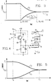
- Figure 3 is a plot of the currents in one channel of the system of Figure 1 as the scaling factor P1 is linearly increased from 0.01 to 1.0.
- the digital scaling circuit of Figure 2 can be replaced by a multiplier receiving an analog control signal Q1 as illustrated in Figure 4.
- an analog scaling signal is applied to terminal 74 and amplified by circuit 76 (comprising transistor TR1, capacitor C3 and resistors R5, R6, R7 and R8) to produce the analog scaling signal Q1.
- Multiplier 78 multiplies the load current signal I LC1 on line 36 by the analog scaling factor Q1 to obtain the scaled load current signal I′ LC1 .
- one of the power source channels could be uncontrolled. That is, the load current signal I LC2 could be applied directly to resistor R3 at an end opposite to the application of the scaled load current signal I′ LC1 . In that case, only the first channel would be adjusted by its control circuits to achieve the desired ratio of output currents between the first and second power sources.
- circuit of Figure 1 performs a method for controlling the operation of a parallel source electrical power system wherein a first load current signal, representative of a load current delivered by at least one phase of a first controlled, variable frequency, variable voltage power source is scaled by a scaling factor representative of the power rating of the first power source to obtain a scaled load current signal.
- the scaled load current signal is combined with a second load current signal, representative of the load current delivered by a second parallel power source to produce a feedback signal.
- the operation of the first power source is then modified in response to the feedback signal such that the ratio of the load currents delivered by the first and second power sources is proportional to the scale factor.
- control circuits are shown on only one phase conductor of the first and second power sources of Figure 1, identical control circuits can be added to each of the phase conductors to produce a multiplicity of feedback signals which can be used by the power source control circuits in accordance with known technology.
Abstract
Description
- This invention relates to control circuits and methods for paralleling AC electrical power systems and, more particularly, to such circuits and methods which are applicable to parallel AC power systems having channels with different power ratings.
- AC electric power systems are generally connected in parallel to increase total system rating, or in certain cases such as airborne power systems, to increase reliability. Typical aircraft AC electrical power systems include two or more identical power channels. These channels may include a constant speed generator with a constant speed drive (CSD) for frequency control, or a variable speed generator with a constant frequency electronic inverter (VSCF). To improve reliability and maximize efficiency, it is generally desired that the total system load be divided equally among the paralleled generators. Load division among AC generators is accomplished by controlling, in a closed loop manner, individual generator voltages and phase angles.
- Other types of electrical power systems which may be operated with parallel channels include photovoltaic, thermionic, fuel cell, or battery systems with inverter outputs such as used for space applications. All of these systems require active control of both real and reactive power flow between the paralleled channels. Controls for paralleling AC systems have been developed for paralleled AC electrical systems. These controls use current transformer loops to sense difference currents between channels. Frequency and voltage controls then drive the difference currents to zero. This type of control system will also work between channels of different power rating if appropriate current transformer ratios are chosen.
- Advanced electrical AC power systems will require that the generating channels have a programmable power rating. Programmability will be needed to accommodate degraded power sources caused by failed rotating rectifiers in brushless AC generators, reduced cooling capacity, damaged fuel cells, etc.
- An object of this invention is to provide a circuit and method for paralleling channels of an AC electric power system wherein individual channels have different and/or variable power ratings.
- Control circuits which perform the method of this invention produce a pair of load current signals which are representative of the load current delivered by two channels of a parallel source electric power system. At least one of these load current signals is scaled by a factor representative of the power rating of one of the power system channels. The scaled load current signal and the other load current signal are combined to produce a feedback signal which is used to modify the operation of one of the paralleled power sources such that the ratio of the load currents delivered by the paralleled power sources is proportional to the scaling factor.
- The scaling factor may be varied in accordance with the power rating of one of the individual power sources. It may also be controlled in order to reduce system transients during application or removal of one of the power sources from the system. The load current signals may be produced by current transformers and scaling can be accomplished by multiplying or dividing one of the load current signals by a digital or analog technique. The scaled load current signal and the other load current signal can be easily combined by applying them to opposite ends of a resistive branch circuit.
- The invention will become more readily apparent from the following description of the preferred embodiment thereof, shown by way of example only, in the accompanying drawings wherein:
- Figure 1 is a schematic diagram, partially in block diagram form, of a paralleled AC electric power system having a control circuit constructed in accordance with one embodiment of the present invention;
- Figure 2 is a schematic diagram of a portion of the control circuit of the system of Figure 1;
- Figure 3 is a plot of the currents produced in one channel of the circuit of Figures 1 and 2;
- Figure 4 is a schematic diagram of an alternative circuit which may be used in the control circuit of the system of Figure 1; and
- Figure 5 is a plot of the currents produced in one channel of the system of Figure 1 using the circuit of Figure 4.
- Referring to the drawings, Figure 1 is a schematic diagram, partially in block diagram form, of a parallel AC electric power system having a control circuit constructed in accordance with the present invention. The system contains first and
second power sources first power source 10 produces a three phase AC output onlines second power source 12 produces a three phase output onlines 20, 22 and 24. A plurality ofpower bus conductors -
Current transformer 32 is inductively coupled to thephase conductor 18 in one channel of the power system. A burden circuit 34 including resistor R1 and capacitor C1 is connected across thecurrent transformer 32 to produce a voltage signal betweenlines phase conductor 18. Afirst scaling circuit 40 applies a scaling factor fromline 42 to the first load current signal onlines line 44. - A second current transformer 46 is inductively coupled to phase conductor 24 of the second power source.
Burden circuit 48 includes resistor R2 and capacitor C2 and is connected across current transformer 46 such that a second voltage signal representative of load current flowing in conductor 24 is produced onlines second scaling circuit 54 applies a second scaling factor received online 56 to the second load current signal onlines - The first and second scaled load current signals are applied to opposite ends of a branch circuit including resistors R3 and R4 and auxiliary contacts K3A and K6A. The resulting voltages appearing across resistors R3 and R4 serve as first and second feedback signals respectively which are amplified by
amplifiers first control circuit 66 which modifies the voltage magnitude and phase angle of the outputs of thefirst power source 10 in accordance with known circuits and techniques, as illustrated in U.S. Patent No. 4,510,399. Similarly, the amplified feedback signal on line 68 is used by thesecond control circuit 70 to modify the voltage magnitude and phase angle of the outputs of thesecond power source 12. - In operation, load current signal ILC1 is proportional to the current I₁ flowing in
phase conductor 18 and load current signal ILC2 is proportional to the current I₂ flowing in phase conductor 24. P₁ and P₂ are scaling factors which are proportional to the power ratings (or desired power contributions) of the first and second power sources respectively. These scaling factors are applied to the load current signals to produce scaled load current signals I′LC1 and I′LC2, which are the load current signals ILC1 and ILC2 divided by P₁ and P₂ respectively. - When the scaled load current signals are applied to resistors R3 and R4 and auxiliary contacts K3A and K6A, the voltages appearing across resistors R3 and R4 are applied to the real and reactive control circuits of each channel. The action of these control circuits is to drive the voltages on resistors R3 and R4 to zero. This is possible only if:

- If scaling factor P₂ is constant, the load sharing of the system will be proportional to scaling factor P₁. This scaling factor may be either a digital or analog signal.
- Figure 2 is a schematic diagram of a portion of the first channel control circuit of Figure 1 which uses a digital scaling factor. This digital scaling factor P₁ is impressed on
data lines 72 of the multiplying digital to analog converter AD7523 which is connected as a divider. The outputs of the multiplying digital to analog converter are applied to anamplifier 5160 to produce the scaled load current signal I′LC1 proportional to ILC1 divided by P₁. - One application of this invention is the reduction in system transients which occur when an unloaded generator is paralleled with a loaded generator. Even if the generators are fully synchronized, there will be a sudden load change on both machines, causing a transient. This transient can be eliminated using the programmable control circuit and method of this invention.
- Consider the system of Figure 1 where the power sources are of equal rating and the generator in the
second power source 12 is fully loaded and the scaling factor P₂ = 1. Relay contact K1, K2, K3 and K3A are initially open. Scaling factor P₁ is initially set to a minimum value of 0.01. Assume that the two power sources are matched exactly in phase and amplitude before paralleling. This can be accomplished with known techniques which are not a part of this invention. When contacts K1, K2, K3 and K3A are closed to parallel the system channels, the generator inpower source 10 will pick up only 1% of the load. If scaling factor P₁ is slowly increased toward a value of 1.0, the generator inpower source 10 will pick up its share of the load as the scaling factor is increased. Since P₂ = 1; the load current IL is the sum of currents I₁ and I₂ ; and I₂ is equal to I₁ divided by scaling factor P₁ , then:
- The digital scaling circuit of Figure 2 can be replaced by a multiplier receiving an analog control signal Q1 as illustrated in Figure 4. In Figure 4, an analog scaling signal is applied to
terminal 74 and amplified by circuit 76 (comprising transistor TR1, capacitor C3 and resistors R5, R6, R7 and R8) to produce the analog scaling signal Q1.Multiplier 78 multiplies the load current signal ILC1 online 36 by the analog scaling factor Q1 to obtain the scaled load current signal I′LC1. For the circuit of Figure 4,
Q1 = 1 + 99e-t/.1 sec (5)
as the transistor TRI is turned off. Then the current inphase conductor 18 becomes:
- Other types of load applications may be obtained by varying the scaling factors. Of course, this invention can be used to eliminate transients as parallel systems are isolated at shutdown or during system configuration changes.
- Although the present invention has been described in terms of what are at present believed to be its preferred embodiments, it will be apparent to those skilled in the art that various changes may be made without departing from the scope of the invention. For example, in Figure 1, one of the power source channels could be uncontrolled. That is, the load current signal ILC2 could be applied directly to resistor R3 at an end opposite to the application of the scaled load current signal I′LC1. In that case, only the first channel would be adjusted by its control circuits to achieve the desired ratio of output currents between the first and second power sources.
- It should now be apparent that the circuit of Figure 1 performs a method for controlling the operation of a parallel source electrical power system wherein a first load current signal, representative of a load current delivered by at least one phase of a first controlled, variable frequency, variable voltage power source is scaled by a scaling factor representative of the power rating of the first power source to obtain a scaled load current signal. The scaled load current signal is combined with a second load current signal, representative of the load current delivered by a second parallel power source to produce a feedback signal. The operation of the first power source is then modified in response to the feedback signal such that the ratio of the load currents delivered by the first and second power sources is proportional to the scale factor.
- It should be further understood that although control circuits are shown on only one phase conductor of the first and second power sources of Figure 1, identical control circuits can be added to each of the phase conductors to produce a multiplicity of feedback signals which can be used by the power source control circuits in accordance with known technology.
Claims (19)
Applications Claiming Priority (2)
| Application Number | Priority Date | Filing Date | Title |
|---|---|---|---|
| US07/080,030 US4754161A (en) | 1987-07-31 | 1987-07-31 | Circuit and method for paralleling AC electrical power systems |
| US80030 | 1998-05-15 |
Publications (3)
| Publication Number | Publication Date |
|---|---|
| EP0302679A2 true EP0302679A2 (en) | 1989-02-08 |
| EP0302679A3 EP0302679A3 (en) | 1990-07-18 |
| EP0302679B1 EP0302679B1 (en) | 1994-06-15 |
Family
ID=22154804
Family Applications (1)
| Application Number | Title | Priority Date | Filing Date |
|---|---|---|---|
| EP88307057A Expired - Lifetime EP0302679B1 (en) | 1987-07-31 | 1988-07-29 | Circuit and method for paralleling AC electrical power systems |
Country Status (5)
| Country | Link |
|---|---|
| US (1) | US4754161A (en) |
| EP (1) | EP0302679B1 (en) |
| JP (1) | JPS6450718A (en) |
| KR (1) | KR890003083A (en) |
| DE (1) | DE3850182D1 (en) |
Cited By (2)
| Publication number | Priority date | Publication date | Assignee | Title |
|---|---|---|---|---|
| EP0435460A2 (en) * | 1989-12-28 | 1991-07-03 | AT&T Corp. | Current sharing control for paralleled power converters |
| EP0410866B1 (en) * | 1989-07-28 | 1994-06-08 | Bull S.A. | Multioutput power converter |
Families Citing this family (15)
| Publication number | Priority date | Publication date | Assignee | Title |
|---|---|---|---|---|
| GB2203868B (en) * | 1987-04-16 | 1991-06-26 | Case Group P L C | Power supply control systems |
| US4874961A (en) * | 1988-10-31 | 1989-10-17 | Sundstrand Corporation | Electrical power generating system having parallel generator control |
| US5142277A (en) * | 1990-02-01 | 1992-08-25 | Gulton Industries, Inc. | Multiple device control system |
| AU646957B2 (en) * | 1991-07-01 | 1994-03-10 | Superconductivity, Inc. | Shunt connected superconducting energy stabilizing system |
| US5317500A (en) * | 1992-08-06 | 1994-05-31 | Sundstrand Corporation | Active no-break power transfer control for a VSCF power generating system |
| US5729059A (en) * | 1995-06-07 | 1998-03-17 | Kilroy; Donald G. | Digital no-break power transfer system |
| US5770897A (en) * | 1996-09-16 | 1998-06-23 | Abb Power T&D Company Inc. | Hybrid solid state switch |
| US7269034B2 (en) | 1997-01-24 | 2007-09-11 | Synqor, Inc. | High efficiency power converter |
| DE19930678C2 (en) * | 1999-03-26 | 2003-03-27 | Metabowerke Gmbh | Electronic power control device, in particular as a welding energy source |
| US6664660B2 (en) * | 2002-01-04 | 2003-12-16 | Delta Electronics, Inc. | Parallel power supply system with over-voltage protection circuit |
| US6813403B2 (en) | 2002-03-14 | 2004-11-02 | Fiber Optic Systems Technology, Inc. | Monitoring of large structures using brillouin spectrum analysis |
| US7514813B2 (en) * | 2002-08-21 | 2009-04-07 | Ebara Corporation | Electric power supply system |
| US20060158807A1 (en) * | 2005-01-18 | 2006-07-20 | Lewis Gerber | Automatic power adapter |
| US7872376B2 (en) * | 2008-05-19 | 2011-01-18 | Zippy Technology Corp. | Multi-input power-switching circuit |
| US10199950B1 (en) | 2013-07-02 | 2019-02-05 | Vlt, Inc. | Power distribution architecture with series-connected bus converter |
Citations (4)
| Publication number | Priority date | Publication date | Assignee | Title |
|---|---|---|---|---|
| US2773994A (en) * | 1953-03-26 | 1956-12-11 | Leeds & Northrup Co | Control of electrical generation |
| FR1511877A (en) * | 1966-02-18 | 1968-02-02 | Licentia Gmbh | Method and device for the automatic balancing of input values at any variation |
| GB2012080A (en) * | 1978-01-09 | 1979-07-18 | Sundstrand Corp | Control system for power sources |
| US4510399A (en) * | 1982-10-07 | 1985-04-09 | Westinghouse Electric Corp. | Demodulator circuit for parallel AC power systems |
Family Cites Families (14)
| Publication number | Priority date | Publication date | Assignee | Title |
|---|---|---|---|---|
| US2862111A (en) * | 1957-12-10 | 1958-11-25 | Westinghouse Electric Corp | Automatic paralleling system |
| US3156828A (en) * | 1959-03-30 | 1964-11-10 | Gen Electric | Protective control for paralleled alternator systems |
| US3069556A (en) * | 1960-02-11 | 1962-12-18 | Westinghouse Electric Corp | Automatic paralleling system |
| US3210556A (en) * | 1962-08-09 | 1965-10-05 | Westinghouse Electric Corp | Automatic paralleling system |
| US3294976A (en) * | 1964-02-27 | 1966-12-27 | Westinghouse Electric Corp | Unbalanced load detection in alternating current systems |
| US3444387A (en) * | 1967-06-20 | 1969-05-13 | Westinghouse Electric Corp | Automatic paralleling system |
| US3539820A (en) * | 1968-01-10 | 1970-11-10 | Westinghouse Electric Corp | Real load unbalance protection circuit for alternating current power sources connected for parallel operation |
| US3588519A (en) * | 1969-08-21 | 1971-06-28 | Westinghouse Electric Corp | Automatic paralleling system |
| US3683199A (en) * | 1970-09-14 | 1972-08-08 | Westinghouse Electric Corp | Over-{11 and underexcitation protection circuit for alternating current power systems |
| JPS5527534B2 (en) * | 1973-03-12 | 1980-07-21 | ||
| DE2649087C2 (en) * | 1976-10-28 | 1983-02-24 | Siemens AG, 1000 Berlin und 8000 München | Power supply device with two regulated power supply devices connected in parallel on the output side |
| US4276590A (en) * | 1979-04-30 | 1981-06-30 | The Perkin-Elmer Corporation | Current sharing modular power system |
| DE3319306C2 (en) * | 1983-05-27 | 1985-04-04 | Siemens AG, 1000 Berlin und 8000 München | Error detection circuit for power supply devices feeding in parallel to a consumer |
| US4520275A (en) * | 1983-12-28 | 1985-05-28 | Rockwell International Corporation | Master and slave power supply control circuits |
-
1987
- 1987-07-31 US US07/080,030 patent/US4754161A/en not_active Expired - Fee Related
-
1988
- 1988-07-29 EP EP88307057A patent/EP0302679B1/en not_active Expired - Lifetime
- 1988-07-29 DE DE3850182T patent/DE3850182D1/en not_active Expired - Lifetime
- 1988-07-29 JP JP63191975A patent/JPS6450718A/en active Pending
- 1988-07-30 KR KR1019880009818A patent/KR890003083A/en not_active Application Discontinuation
Patent Citations (4)
| Publication number | Priority date | Publication date | Assignee | Title |
|---|---|---|---|---|
| US2773994A (en) * | 1953-03-26 | 1956-12-11 | Leeds & Northrup Co | Control of electrical generation |
| FR1511877A (en) * | 1966-02-18 | 1968-02-02 | Licentia Gmbh | Method and device for the automatic balancing of input values at any variation |
| GB2012080A (en) * | 1978-01-09 | 1979-07-18 | Sundstrand Corp | Control system for power sources |
| US4510399A (en) * | 1982-10-07 | 1985-04-09 | Westinghouse Electric Corp. | Demodulator circuit for parallel AC power systems |
Cited By (3)
| Publication number | Priority date | Publication date | Assignee | Title |
|---|---|---|---|---|
| EP0410866B1 (en) * | 1989-07-28 | 1994-06-08 | Bull S.A. | Multioutput power converter |
| EP0435460A2 (en) * | 1989-12-28 | 1991-07-03 | AT&T Corp. | Current sharing control for paralleled power converters |
| EP0435460A3 (en) * | 1989-12-28 | 1992-04-15 | American Telephone And Telegraph Company | Current sharing control for paralleled power converters |
Also Published As
| Publication number | Publication date |
|---|---|
| US4754161A (en) | 1988-06-28 |
| EP0302679A3 (en) | 1990-07-18 |
| DE3850182D1 (en) | 1994-07-21 |
| JPS6450718A (en) | 1989-02-27 |
| EP0302679B1 (en) | 1994-06-15 |
| KR890003083A (en) | 1989-04-12 |
Similar Documents
| Publication | Publication Date | Title |
|---|---|---|
| EP0302679B1 (en) | Circuit and method for paralleling AC electrical power systems | |
| US3718847A (en) | Adjustable speed polyphase a-c motor drive utilizing an in-phase current signal for motor control | |
| Zhang et al. | Operation of autonomous AC microgrid at constant frequency and with reactive power generation from grid-forming, grid-supporting and grid-feeding generators | |
| MY119456A (en) | Pulsed width modulation method for power transforming apparatus | |
| US4560917A (en) | Static VAR generator having reduced harmonics | |
| US6433520B1 (en) | Dc power regulator incorporating high power ac to dc converter with controllable dc voltage and method of use | |
| US4311920A (en) | Emergency power source | |
| JPS6045825A (en) | Method and circuit for controlling capacity of static type reactive power generator | |
| US3401327A (en) | Inverter circuit having increased frequency starting | |
| De Heredia et al. | Analysis of multi-resonant current control structures and tuning methods | |
| ES377339A1 (en) | Electric power apparatus comprising converter, filter, regulator, and means for dynamically stabilizing the filter | |
| Jyothish et al. | Load sharing control and circulating current minimization of parallel DC-DC converters based on droop index | |
| JP3259308B2 (en) | Inverter device and uninterruptible power supply using the same | |
| EP1128538A2 (en) | Control system adapted to control operation of an AC/DC converter | |
| US4225911A (en) | Apparatus and method for reducing overvoltage transients on the outputs of a VSCF system | |
| JPH02228296A (en) | Discharge circuit and discharge method of dc filter capacitor | |
| SU763923A1 (en) | Device for simulating energy systems | |
| US4383183A (en) | Control arrangement for a uniform load distribution of at least two power supply devices connected in parallel at the output side | |
| US2808521A (en) | Power supply system | |
| AU4304799A (en) | Method and device for reducing the current in the neutral conductor | |
| US4135126A (en) | Device for noncontact switching of loaded transformer tappings | |
| SU653676A1 (en) | Method of automatic regulation of voltage in electric circuits | |
| Khamooshpoor et al. | Comparison of Two Approaches of Resolving Power Sharing Error in Droop Based DC Microgrids. | |
| Han et al. | Cascaded H-Bridge Based Islanded Microgrid with Variable Magnitude Power Sharing and PCC Voltage Management | |
| JPS6194523A (en) | Load distribution system |
Legal Events
| Date | Code | Title | Description |
|---|---|---|---|
| PUAI | Public reference made under article 153(3) epc to a published international application that has entered the european phase |
Free format text: ORIGINAL CODE: 0009012 |
|
| AK | Designated contracting states |
Kind code of ref document: A2 Designated state(s): DE FR GB |
|
| PUAL | Search report despatched |
Free format text: ORIGINAL CODE: 0009013 |
|
| AK | Designated contracting states |
Kind code of ref document: A3 Designated state(s): DE FR GB |
|
| 17P | Request for examination filed |
Effective date: 19901228 |
|
| RAP1 | Party data changed (applicant data changed or rights of an application transferred) |
Owner name: SUNDSTRAND CORPORATION |
|
| 17Q | First examination report despatched |
Effective date: 19921103 |
|
| GRAA | (expected) grant |
Free format text: ORIGINAL CODE: 0009210 |
|
| AK | Designated contracting states |
Kind code of ref document: B1 Designated state(s): DE FR GB |
|
| PG25 | Lapsed in a contracting state [announced via postgrant information from national office to epo] |
Ref country code: FR Free format text: THE PATENT HAS BEEN ANNULLED BY A DECISION OF A NATIONAL AUTHORITY Effective date: 19940615 |
|
| ET | Fr: translation filed | ||
| REF | Corresponds to: |
Ref document number: 3850182 Country of ref document: DE Date of ref document: 19940721 |
|
| PG25 | Lapsed in a contracting state [announced via postgrant information from national office to epo] |
Ref country code: GB Effective date: 19940915 |
|
| PG25 | Lapsed in a contracting state [announced via postgrant information from national office to epo] |
Ref country code: DE Effective date: 19940916 |
|
| PLBE | No opposition filed within time limit |
Free format text: ORIGINAL CODE: 0009261 |
|
| STAA | Information on the status of an ep patent application or granted ep patent |
Free format text: STATUS: NO OPPOSITION FILED WITHIN TIME LIMIT |
|
| GBPC | Gb: european patent ceased through non-payment of renewal fee |
Effective date: 19940915 |
|
| 26N | No opposition filed |