DE69707704T3 - HYBRID GENERATOR DEVICE - Google Patents
HYBRID GENERATOR DEVICE Download PDFInfo
- Publication number
- DE69707704T3 DE69707704T3 DE69707704T DE69707704T DE69707704T3 DE 69707704 T3 DE69707704 T3 DE 69707704T3 DE 69707704 T DE69707704 T DE 69707704T DE 69707704 T DE69707704 T DE 69707704T DE 69707704 T3 DE69707704 T3 DE 69707704T3
- Authority
- DE
- Germany
- Prior art keywords
- output
- voltage
- speed
- current
- load
- Prior art date
- Legal status (The legal status is an assumption and is not a legal conclusion. Google has not performed a legal analysis and makes no representation as to the accuracy of the status listed.)
- Expired - Lifetime
Links
Images


Classifications
-
- H—ELECTRICITY
- H02—GENERATION; CONVERSION OR DISTRIBUTION OF ELECTRIC POWER
- H02P—CONTROL OR REGULATION OF ELECTRIC MOTORS, ELECTRIC GENERATORS OR DYNAMO-ELECTRIC CONVERTERS; CONTROLLING TRANSFORMERS, REACTORS OR CHOKE COILS
- H02P9/00—Arrangements for controlling electric generators for the purpose of obtaining a desired output
- H02P9/48—Arrangements for obtaining a constant output value at varying speed of the generator, e.g. on vehicle
-
- H—ELECTRICITY
- H02—GENERATION; CONVERSION OR DISTRIBUTION OF ELECTRIC POWER
- H02J—CIRCUIT ARRANGEMENTS OR SYSTEMS FOR SUPPLYING OR DISTRIBUTING ELECTRIC POWER; SYSTEMS FOR STORING ELECTRIC ENERGY
- H02J9/00—Circuit arrangements for emergency or stand-by power supply, e.g. for emergency lighting
- H02J9/04—Circuit arrangements for emergency or stand-by power supply, e.g. for emergency lighting in which the distribution system is disconnected from the normal source and connected to a standby source
- H02J9/06—Circuit arrangements for emergency or stand-by power supply, e.g. for emergency lighting in which the distribution system is disconnected from the normal source and connected to a standby source with automatic change-over, e.g. UPS systems
- H02J9/066—Circuit arrangements for emergency or stand-by power supply, e.g. for emergency lighting in which the distribution system is disconnected from the normal source and connected to a standby source with automatic change-over, e.g. UPS systems characterised by the use of dynamo-electric machines
-
- H—ELECTRICITY
- H02—GENERATION; CONVERSION OR DISTRIBUTION OF ELECTRIC POWER
- H02P—CONTROL OR REGULATION OF ELECTRIC MOTORS, ELECTRIC GENERATORS OR DYNAMO-ELECTRIC CONVERTERS; CONTROLLING TRANSFORMERS, REACTORS OR CHOKE COILS
- H02P9/00—Arrangements for controlling electric generators for the purpose of obtaining a desired output
- H02P9/04—Control effected upon non-electric prime mover and dependent upon electric output value of the generator
-
- H—ELECTRICITY
- H02—GENERATION; CONVERSION OR DISTRIBUTION OF ELECTRIC POWER
- H02P—CONTROL OR REGULATION OF ELECTRIC MOTORS, ELECTRIC GENERATORS OR DYNAMO-ELECTRIC CONVERTERS; CONTROLLING TRANSFORMERS, REACTORS OR CHOKE COILS
- H02P2101/00—Special adaptation of control arrangements for generators
- H02P2101/15—Special adaptation of control arrangements for generators for wind-driven turbines
-
- Y—GENERAL TAGGING OF NEW TECHNOLOGICAL DEVELOPMENTS; GENERAL TAGGING OF CROSS-SECTIONAL TECHNOLOGIES SPANNING OVER SEVERAL SECTIONS OF THE IPC; TECHNICAL SUBJECTS COVERED BY FORMER USPC CROSS-REFERENCE ART COLLECTIONS [XRACs] AND DIGESTS
- Y02—TECHNOLOGIES OR APPLICATIONS FOR MITIGATION OR ADAPTATION AGAINST CLIMATE CHANGE
- Y02B—CLIMATE CHANGE MITIGATION TECHNOLOGIES RELATED TO BUILDINGS, e.g. HOUSING, HOUSE APPLIANCES OR RELATED END-USER APPLICATIONS
- Y02B10/00—Integration of renewable energy sources in buildings
- Y02B10/70—Hybrid systems, e.g. uninterruptible or back-up power supplies integrating renewable energies
Landscapes
- Engineering & Computer Science (AREA)
- Power Engineering (AREA)
- Business, Economics & Management (AREA)
- Emergency Management (AREA)
- Control Of Eletrric Generators (AREA)
- Dc-Dc Converters (AREA)
- Regulating Braking Force (AREA)
- Rectifiers (AREA)
Description
HINTERGRUND DER ERFINDUNGBACKGROUND OF THE INVENTION
Die vorliegende Erfindung betrifft Generatorgeräte, die zur Lieferung von Leistungen verwendet werden können, die erheblichen zeitlichen Veränderungen unterworfen sind.The present invention relates to generator sets that can be used to provide services that are subject to significant temporal changes.
In herkömmlichen elektrischen Generatorgeräten betreibt ein Motor oder eine andere Antriebsvorrichtung einen synchronen Wechselstromgenerator mit nominell konstanter Drehzahl, die so berechnet ist, dass ein elektrischer Wechselstromausgang der richtigen Frequenz geliefert wird. Im praktischen Betrieb bleibt die Motordrehzahl nicht genau konstant, was zu unerwünschten Frequenzvariationen des elektrischen Ausgangs eines solchen Generatorgerätes führt.In conventional electrical generator sets, a motor or other drive device operates a nominally constant speed synchronous alternator that is calculated to provide an AC electrical output of the correct frequency. In practical operation, the engine speed does not remain exactly constant, which leads to undesirable frequency variations of the electrical output of such a generator device.
Um maximale Leistung erbringen zu können, muss ein solches Generatorgerät eine entsprechende Größe besitzen, was auf Grund der Tatsache, dass die durchschnittliche Belastung typischerweise nur etwa 20% der Spitzenlast beträgt, eine große Vergeudung bedeuten kann. Es gibt zahlreiche Anwendungen wie Schweißen, Batterieladen und Start/Betrieb elektrischer Motoren, wo die geforderte Leistung großen Schwankungen unterliegt und wo das Generatorgerät nur zeitweise starken Belastungen ausgesetzt ist. Es ist deshalb wünschenswert, ein Generatorgerät einzusetzen, das in seiner Anwendung effizient unter leichten Belastungsbedingungen arbeiten kann.To provide maximum performance, such a generator set must be of a size which, due to the fact that the average load is typically only about 20% of the peak load, can be a waste. There are numerous applications such as welding, battery charging and starting / operating electric motors, where the required power is subject to great fluctuations and where the generator unit is exposed only occasionally to heavy loads. It is therefore desirable to use a generator apparatus which can operate efficiently under light load conditions in its application.
Drehzahlvariable Generatorgeräte wurden vorgeschlagen, (siehe beispielsweise
”Development of an Experimental Hybrid Power System Incorporating a Variable Speed Diesel Generator” (Entwicklung eines experimentellen Hybridstromversorgungssystems mit einem Dieselgenerator mit veränderlicher Drehzahl), Stein et al., vorgestellt anlässlich der American Wind Energy Conference (Amerikanische Windenergiekonferenz) 1994, offenbart ein Dieselsystem mit veränderlicher Drehzahl. In diesem System wird die Leistung eines Diesel- und Synchrongenerators über einen Gleichrichter einem Boost-Schaltkreis und danach über einen Inverter einer Ladung zugeführt. Der Synchrongenerator und der Boost-Schaltkreis sind jeweils spannungsgeregelt. Ein Steuerungsrechner reagiert auf die an der Ladung geforderte Energie, um die Drehzahl des Dieselmotors zu ändern."Development of an Experimental Hybrid Power System Incorporating a Variable Speed Diesel Generator", developed by Stein et al., At the American Wind Energy Conference in 1994, discloses a diesel system with variable speed. In this system, the power of a diesel and synchronous generator is fed through a rectifier to a boost circuit and then through an inverter to a charge. The synchronous generator and the boost circuit are each voltage controlled. A control computer responds to the energy required at the charge to change the speed of the diesel engine.
Aufgabe der Erfindung ist die Schaffung eines Hybridgeneratorgerätes, welches erhebliche Lastschwankungen bei gleichzeitig gutem Wirkungsgrad bewältigen kann.The object of the invention is to provide a hybrid generator device which can cope with significant load fluctuations with good efficiency.
ZUSAMMENFASSUNG DER ERFINDUNGSUMMARY OF THE INVENTION
Erfindungsgemäß ist ein Stromversorgungsgerät gemäß Anspruch 1 vorgesehen.According to the invention, a power supply device according to
Das Gerät kann wenigstens eine erste Energiespeichereinrichtung umfassen, die zum Laden aus dem Gleichstromzwischenausgang und zum Entladen von Energie in den Gleichstromzwischenausgang angeordnet ist, wenn die Spannung des Gleichstromzwischenausgangs unter einen Nennwert abfällt.The apparatus may include at least a first energy storage device arranged to be charged from the DC intermediate output and to discharge energy into the DC intermediate output when the DC intermediate output voltage falls below a nominal value.
Stattdessen oder außerdem kann das Gerät eine Zusatzlast-Steuereinrichtung umfassen, die zum Feststellen des Anschlusses einer schweren Zusatzlast an die Ausgangseinrichtung und zur Steuerung der Kraftzufuhr für die Zusatzlast angeordnet ist, um dadurch eine übermäßige Belastung der Ausgangseinrichtung zu vermeiden.Instead, or in addition, the apparatus may include an auxiliary load control means arranged to detect the connection of a heavy additional load to the output means and to control the power supply for the additional load to thereby avoid excessive loading of the output means.
Vorzugsweise umfasst das Gerät wenigstens eine zweite Energiespeichereinrichtung, einen Ladekreis, der zum Laden der zweiten Energiespeichereinrichtung aus dem Gleichstromzwischenausgang der Wandlereinrichtung angeordnet ist, und einen Entladekreis, der zum Entladen der zweiten Energiespeichereinrichtung parallel zur ersten Energiespeichereinrichtung angeordnet ist, wenn die Spannung des Gleichstromzwischenausgangs unter eine zweite Spannungsschwelle unter der ersten Spannungsschwelle abfällt.Preferably, the apparatus comprises at least a second energy storage device, a charging circuit arranged to charge the second energy storage device from the DC intermediate output of the converter device, and a discharge circuit arranged to discharge the second energy storage device in parallel with the first energy storage device when the DC intermediate voltage output is below a second voltage threshold drops below the first voltage threshold.
In einer Ausführungsform umfasst das Gerät eine dritte Energiespeichereinrichtung, einen Ladekreis, der zum Laden der dritten Energiespeichereinrichtung aus einer elektrischen Quelle angeordnet ist, und eine Zusatzwandlereinrichtung, die zum Entladen der dritten Energiespeichereinrichtung parallel zur ersten und zweiten Energiespeichereinrichtung angeordnet ist, wenn die zweite Energiespeichereinrichtung wenigstens teilweise entladen ist.In one embodiment, the apparatus comprises a third energy storage device, a charging circuit arranged to charge the third energy storage device from an electrical source, and an auxiliary conversion device arranged to discharge the third energy storage device in parallel with the first and second energy storage devices when the second energy storage device is at least partially discharged.
Die ersten und zweiten Energiespeichereinrichtungen sind vorzugsweise Kondensatoren und die dritte Energiespeichereinrichtung ist vorzugsweise eine Batterie.The first and second energy storage devices are preferably capacitors and the third energy storage device is preferably a battery.
Das Gerät kann einen Drehzahlsensor zum Überwachen der Drehzahl des Motors/Generators und zum Erzeugen eines darauf bezogenen Drehzahlausgangssignals umfassen, und eine Funktionsgeneratoreinrichtung zum Erzeugen eines Stromsignals aus dem Drehzahlausgangssignal, wobei das Stromsignal eine Leistungs-/Drehzahlkennlinie des Motors darstellt und von der Steuereinrichtung zur Optimierung des Motorbetriebes genutzt wird.The apparatus may include a speed sensor for monitoring the speed of the motor / generator and for generating a related speed output signal, and function generator means for generating a current signal from the speed output signal, wherein the current signal represents a power / speed characteristic of the motor and the controller for optimization the engine operation is used.
Das Gerät kann ferner Umgebungsdruck- und Umgebungstemperatursensoren zum Überwachen des Umgebungsdrucks und der Umgebungstemperatur und zum Erzeugen von jeweiligen Druck- und Temperaturausgangssignalen umfassen, und kann des weiteren jeweilige Druck- und Temperaturfunktionsgeneratoren umfassen, zum Erzeugen von Ausgängen, umfassend Motorleistungsverlustkenngrößen zum Ausgleichen von Schwankungen in Umgebungsbetriebsdruck- und Umgebungstemperatur.The apparatus may further include ambient pressure and ambient temperature sensors for monitoring ambient pressure and temperature and generating respective pressure and temperature output signals, and may further comprise respective pressure and temperature function generators for generating outputs including engine power loss characteristics for compensating for variations in ambient operating pressure - and ambient temperature.
Das Gerät kann auch einen Abgastemperatursensor umfassen, der zum Überwachen der Temperatur der Motorabgase und zum Erzeugen eines Ausgangssignals für die Abgastemperatur angeordnet ist, einen Abgastemperaturfunktionsgenerator zum Erzeugen eines Kennkurvensignals für die Abgastemperatur/Drehzahl-Last aus dem Drehzahlausgangssignal, und ein Steuerelement zum Erzeugen eines Fehlersignals aus der Differenz zwischen dem Ausgangssignal für die Abgastemperatur und dem Kennkurvensignal für die Abgastemperatur/Drehzahl-Last, um dadurch Faktoren auszugleichen, die die Motorabgastemperatur beeinflussen.The apparatus may also include an exhaust gas temperature sensor arranged to monitor the temperature of the engine exhaust gases and to generate an exhaust temperature output signal, an exhaust temperature function generator to generate an exhaust gas temperature / speed load characteristic signal from the speed output signal, and a control signal to generate an error signal from the difference between the exhaust gas temperature output signal and the exhaust gas temperature / speed load characteristic curve signal to thereby compensate for factors affecting the engine exhaust temperature.
KURZE BESCHREIBUNG DER ZEICHNUNGENBRIEF DESCRIPTION OF THE DRAWINGS
BESCHREIBUNG DER AUSFÜHRUNGSBEISPIELEDESCRIPTION OF THE EMBODIMENTS
Die Entkopplungswandlereinrichtung
Die Entkopplungswandlereinrichtung
In
Ein erster Spannungssensor
Der Ausgang V_1 des Spannungssensors wird auch auf einen Steuerkreis
Das Gerät gemäß
Das Gerät gemäß
Gleichzeitig regelt der Wandler
Sobald die Größe VDC, gemessen vom ersten Spannungssensor
Sobald sich der Lastkraftbedarf verringert, wird das Gleichgewicht zwischen der Quelle und der Last wieder gestört. In dem Fall steigt die Spannung VDC an und die Spannungs-/Drehzahlsteuerschleife wird aktiv zur Verringerung der Ausgangsleistung der Quelle (z. B. die Motordrehzahl im Falle einer Motor/Generatoreinheit), Verringerung der Ausgangsleistung und Spannung der Quelle, wodurch es dem Wandler
In der oben beschriebenen Betriebsweise wird eine Art Stromsteuerung in Kombination mit dem Hauptspannungssteuerungssystem verwendet. Durch Steuerung oder Beschränkung des der Quelle entzogenen Stromes wird verursacht, dass die Spannung VDC des Gleichstromzwischenausgangs sich mit Änderungen im Lastbedarf ändert innerhalb eines festgelegten über den Wandler
Das Gerät gemäß
Erhöht sich der Laststrombedarf (das Produkt der Gleichstromspannung und des Gleichstrom-Stromes am Gleichstromzwischenausgang) muss sich der Strom im Wandler und somit der der Quelle
Wenn sich die Größe der Last erhöht, und da die Größe von VDC im Wesentlichen konstant gehalten wird, versucht der Wandler
Wenn umgekehrt der Laststrombedarf zurückgeht, verlangt der Wandler
In dieser Betriebsweise wird die Quelle durch den Wandler
In beiden oben beschriebenen Steuersystemen erweist sich die Verwendung des Entkopplungswandlers
Zahlreiche Varianten und Abänderungen des oben beschriebenen basischen Gerätes sind möglich. Numerous variants and modifications of the basic device described above are possible.
Zum Beispiel ist es möglich, zwei oder mehr zusätzliche Energiequellen anstelle der Energiespeichereinrichtung
Beim Feststellen einer Last schneidet der Schnittstellenkreis
Um ein Beispiel zu nennen, wenn die Zusatzlast ein Gleichstrom-Nebenschlussmotor ist, dann legt die Schnittstelle eine Spannung an die Nebenschlusswindung an und lässt dann die Spannung am Ankerkreis ansteigen bis zum Betriebsnennwert. Handelt es sich bei der Zusatzlast um einen Wechselstrommotor, kann die Schnittstelle entweder die aufgelegte Spannung reduzieren wie in einem Soft-Startkreis oder die Spannungs- und Frequenzproportionalität verringern wie in einem verstellbaren Drehzahlantrieb (ASD). Die Zusatzlast kann auch einfach abgeschnitten und wieder verbunden werden, wenn die Quelle ihr maximales Leistungsniveau erreicht hat.As an example, if the additional load is a DC shunt motor, then the interface applies a voltage to the shunt winding and then increases the voltage across the armature circuit to the rated operating value. If the auxiliary load is an AC motor, the interface can either reduce the applied voltage as in a soft-starting circuit or reduce the voltage and frequency proportionality as in an adjustable speed drive (ASD). The extra load can also be easily cut off and reconnected once the source has reached its maximum level of performance.
Der Mess- und Steuerkreis
Um auch solchen Kondensatoren zu genügen, die veränderliche Spannungseinrichtungen sind (d. h. die Kontaktspannung eines Kondensators ändert sich gemäß seinem Ladezustand), kann der Gleichstrom-Gleichstrom-Wandler
Die in
Die Batterie
Man sieht also, dass die oben beschriebene Ausführungsform der Erfindung mit mehrfach steuerbaren elektrischen Quellen ein Hybridgeneratorsystem darstellt, welches eine Last oder mehrere Lasten aus zwei oder mehreren verschiedenen Quellen beliefern kann, je nach dem festgelegten Steuersystem. Somit schafft die vorliegende Erfindung große Flexibilität im Aufbau von Hybridgeneratorsystemen für bestimmte Anwendungen.It will thus be seen that the multi-controllable electrical source embodiment of the invention described above is a hybrid generator system that can supply one or more loads from two or more different sources, depending on the control system established. Thus, the present invention provides great flexibility in designing hybrid generator systems for particular applications.
In der gezeigten Darstellung entlädt die erste Energiespeichereinrichtung
Obwohl die Batterie
In der Anordnung gemäß
Anstelle von Kondensatoren oder einer Batterie können auch andere Arten von Energiespeichereinrichtungen wie eine Schwungradmotor/generatoranordnung verwendet werden. Der wichtige Maßstab, abgesehen von der Verwendung entsprechender Schnittstellen, ist die Anpassung der Art der gewählten Energiespeichereinrichtung an sowohl die vorübergehenden als auch die langfristigen Energieerfordernisse, die von den zusätzlichen Speichereinrichtungen erfüllt werden müssen.Instead of capacitors or a battery, other types of energy storage devices such as a flywheel motor / generator assembly may be used. The important yardstick, apart from the use of appropriate interfaces, is the adaptation of the type of energy storage device chosen to both the transient and long-term energy needs that must be met by the additional storage devices.
Gemäß
Der Steuerkreis des Gerätes schließt einen Spannungssteuerkreis
Der Gleichstrom-Gleichstrom-Wandler
Das Drehzahlsignal Va2 wird auch dem Bezugsstromfunktionsgenerator
Wird die Größe der Last
Zusätzlich zur primären Energiespeichereinrichtung (Kondensator)
Der Lade-/Entladewandler
Der Entladeregler
Der Laderegler
Wegen des Vorhandenseins der Sperrdiode D5 kann die Reservebatterie BAT über den Lade-/Entladewandler
Der Batteriebezugsspannungsfunktionsgenerator
Im gezeigten Beispiel wird die Energie für den Batterieladewandler
Da die Steuerkreise des Lade-/Entladewandlers
Der Entladeregler
Ein Entladen über den Wandler
Obwohl man herkömmlicherweise annehmen würde, dass die Anbringung eines Gleichstrom-Gleichstrom-Wandlers zwischen dem Ausgang eines Generators und einer Last den Wirkungsgrad des Gerätes verringern würde, da der Wirkungsgrad des Wandlers geringer ist als 100%, wird trotzdem eine vorteilhafte Wirkung erzielt. Die Zwischenschaltung des Gleichstrom-Gleichstrom-Wandlers zwischen den Generator/Gleichrichter und die Last bewirkt eine ”Entkopplung” oder Isolierung des Generatorausganges vom Gleichstromzwischenausgang des Systems, wodurch das System in die Lage versetzt wird, in einem sehr viel größeren Bereich von Motor-/Generatordrehzahlen bei trotzdem gutem Wirkungsgrad betrieben zu werden. Dadurch kann das erfindungsgemäße Gerät selbst unter geringer Last effizient betrieben werden im Vergleich zu Systemen gemäß Stand der Technik, die mit dem Motor/Generator bei geringer Last nicht effizient wirksam arbeiten können und stattdessen für diesen Zweck eine Batterie verwenden müssen. Der Kostenaufwand, der sich aus den Verlusten des Wandlers ergibt, ist vernachlässigbar im Vergleich zum erhöhten Kraftstoffwirkungsgrad und dem elektrischen Gesamtwirkungsgrad des erfindungsgemäßen Gerätes.Although it would conventionally be assumed that the attachment of a DC-DC converter between the output of a generator and a load would reduce the efficiency of the device, since the efficiency of the converter is less than 100%, a beneficial effect is still achieved. Interposing the DC / DC converter between the generator / rectifier and the load effects "decoupling" or isolation of the generator output from the DC intermediate output of the system, thereby enabling the system to operate in a much wider range of motor / generator speeds to be operated in spite of good efficiency. Thereby, the device according to the invention can be operated efficiently even under low load compared to prior art systems that can not efficiently operate with the motor / generator under light load and instead have to use a battery for this purpose. The cost that results from the losses of the converter is negligible compared to the increased fuel efficiency and the overall electrical efficiency of the device according to the invention.
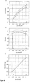
Die
Gemäß
Beim Punkt für Mindestdrehzahlbetrieb (A) lässt man die Lastkraft bis Punkt 1 steigen (siehe
Die Verwendung des steuerbaren Entkopplungswandlers zwischen dem Generator und dem Gleichstromzwischenausgang des Systems schafft die Möglichkeit, die Belastung des Motors im variablen Drehzahlbereich zwischen den Punkten 1 und 2 gemäß der gewünschten Kurve zu steuern, einschließlich der Grenzen an den Mindest- und Höchstdrehzahlbetriebspunkten A und B. Die Steuerung wird erreicht indem man den dem Generator entzogenen Strom gemäß einer gewünschten Bezugsstromkennzahlkurve bestimmt.
In
Die
In
Die oben gezeigten Figuren stellen ein verhältnismäßig einfaches Steuersystem für den optimalen Betrieb eines Motors entsprechend seiner Leistungskennzeichen wie Kraft gegen Drehzahl, die Lastminderungsfaktoren etc. dar. Die Motordrehzahl wird zwischen einer Mindestbetriebsdrehzahl und einer Höchstbetriebsdrehzahl so variiert, dass ihre Last einer optimalen Kraft-/Drehzahlkurve entspricht, die man aus den Leistungskurven des Motors entnimmt, wobei man jeweils, wenn die Last erhöht wird, eine Reservekapazität für die Beschleunigung zulässt.The figures shown above represent a relatively simple control system for optimum operation of an engine according to its performance characteristics such as force versus speed, load reduction factors, etc. The engine speed is varied between a minimum operating speed and a maximum operating speed such that its load is an optimum power / speed curve which is taken from the performance curves of the engine, wherein each, when the load is increased, a reserve capacity for the acceleration allows.
Betrachtet man die Kraft-/Drehzahlkennlinie des Motors als gegeben und wenn man ferner berücksichtigt, dass sich die Ausgangsspannung eines Dauermagnetgenerators linear mit der Drehzahl ändert, wird eine verhältnismäßig einfache Steuerung des Stromes gemäß der Kennzahlkurve (
In einem vereinfachten Steuersystem kann der Strom auf einfache Weise konstant eingestellt werden während der Motor in seinem variablen Drehzahlbetriebsbereich arbeitet. In dem Fall ist die Strom-/Drehzahlkurve in
In ähnlicher Weise wird gemäß
In
Die Abgastemperatur ist eine Bezugsgröße, welche der Umgebungstemperatur, Druck (einem Maß für die Höhe), Last und dem allgemeinen mechanischen Zustand des Motors und der Qualität des verwendeten Kraftstoffes proportional ist. Deshalb kann durch einfache Überwachung der Motorabgastemperatur und durch Korrektur für deren Variationen in Bezug auf ein Abgastemperaturbezugssignal die Leistungsherabsetzung des Motors bequem berücksichtigt werden indem man die Drehzahl für einen gegebenen Lastkraftbedarf erhöht, um für Bedingungen wie schlechte Treibstoffqualität, hohe Umgebungstemperatur, große Höhe oder schlechter Zustand oder Einstellung des Motors zu kompensieren.The exhaust gas temperature is a reference that is proportional to the ambient temperature, pressure (a measure of altitude), load and the general mechanical condition of the engine and the quality of the fuel used. Therefore, by simply monitoring the engine exhaust temperature and correcting for its variations in exhaust gas temperature reference signal, the power reduction of the engine can be conveniently accommodated by increasing the speed for a given load demand for conditions such as poor fuel quality, high ambient temperature, high altitude, or poor condition or adjusting the motor to compensate.
Gemäß
Das Motordrehmomentbezugssignal gemäß
Claims (9)
Applications Claiming Priority (4)
| Application Number | Priority Date | Filing Date | Title |
|---|---|---|---|
| ZA9610787 | 1996-12-20 | ||
| ZA9610787 | 1996-12-20 | ||
| EP97954466.5A EP0947042B2 (en) | 1996-12-20 | 1997-12-19 | Hybrid generator apparatus |
| PCT/EP1997/007273 WO1998028832A1 (en) | 1996-12-20 | 1997-12-19 | Hybrid generator apparatus |
Publications (3)
| Publication Number | Publication Date |
|---|---|
| DE69707704D1 DE69707704D1 (en) | 2001-11-29 |
| DE69707704T2 DE69707704T2 (en) | 2002-06-27 |
| DE69707704T3 true DE69707704T3 (en) | 2013-07-11 |
Family
ID=25586109
Family Applications (1)
| Application Number | Title | Priority Date | Filing Date |
|---|---|---|---|
| DE69707704T Expired - Lifetime DE69707704T3 (en) | 1996-12-20 | 1997-12-19 | HYBRID GENERATOR DEVICE |
Country Status (18)
| Country | Link |
|---|---|
| US (1) | US6175217B1 (en) |
| EP (1) | EP0947042B2 (en) |
| JP (1) | JP2001507199A (en) |
| KR (1) | KR100603245B1 (en) |
| CN (1) | CN1104077C (en) |
| AP (1) | AP1042A (en) |
| AT (1) | ATE207668T1 (en) |
| AU (1) | AU730833B2 (en) |
| BR (1) | BR9714496A (en) |
| CA (1) | CA2275617C (en) |
| DE (1) | DE69707704T3 (en) |
| ES (1) | ES2167809T5 (en) |
| MY (1) | MY124133A (en) |
| PL (1) | PL186824B1 (en) |
| PT (1) | PT947042E (en) |
| RU (1) | RU2216847C2 (en) |
| WO (1) | WO1998028832A1 (en) |
| ZA (1) | ZA9711503B (en) |
Families Citing this family (179)
| Publication number | Priority date | Publication date | Assignee | Title |
|---|---|---|---|---|
| US6600240B2 (en) * | 1997-08-08 | 2003-07-29 | General Electric Company | Variable speed wind turbine generator |
| US6420795B1 (en) * | 1998-08-08 | 2002-07-16 | Zond Energy Systems, Inc. | Variable speed wind turbine generator |
| JP4096430B2 (en) * | 1998-12-10 | 2008-06-04 | 松下電器産業株式会社 | Fuel cell device |
| JP4115629B2 (en) * | 1999-05-25 | 2008-07-09 | 本田技研工業株式会社 | Power supply system |
| FR2797535B1 (en) * | 1999-08-09 | 2001-10-12 | Leroy Somer | ELECTRICITY GENERATION DEVICE |
| JP2001095107A (en) * | 1999-09-21 | 2001-04-06 | Yamaha Motor Co Ltd | Method for controlling power source of hybrid-driven mobile |
| US6285089B1 (en) * | 1999-11-24 | 2001-09-04 | Siemens Westinghouse Power Corporation | Induction static start for a turbine generator with a brushless exciter and associated methods |
| US6456514B1 (en) | 2000-01-24 | 2002-09-24 | Massachusetts Institute Of Technology | Alternator jump charging system |
| US6912142B2 (en) | 2000-01-24 | 2005-06-28 | Massachusetts Institute Of Technology | Alternator control circuit and related techniques |
| EP2083498B1 (en) | 2000-01-28 | 2010-12-08 | Cummins Generator Technologies Limited | An AC power generating system |
| US6915185B2 (en) * | 2000-03-24 | 2005-07-05 | Matsushita Electric Industrial Co., Ltd. | Power supply system |
| US6651760B2 (en) * | 2000-04-05 | 2003-11-25 | Borealis Technical Limited | Thermionic automobile |
| US7419022B2 (en) * | 2000-04-05 | 2008-09-02 | Borealis Technical Limited | Thermionic power unit |
| US6428918B1 (en) * | 2000-04-07 | 2002-08-06 | Avista Laboratories, Inc. | Fuel cell power systems, direct current voltage converters, fuel cell power generation methods, power conditioning methods and direct current power conditioning methods |
| JP2002034179A (en) * | 2000-07-14 | 2002-01-31 | Toshiba Corp | Power controller |
| JP3724634B2 (en) * | 2000-08-28 | 2005-12-07 | 本田技研工業株式会社 | Engine power generator and cogeneration system |
| DE10044096A1 (en) * | 2000-09-07 | 2002-04-04 | Aloys Wobben | Off-grid and method for operating an off-grid |
| JP2002101560A (en) * | 2000-09-26 | 2002-04-05 | Honda Motor Co Ltd | Power generator |
| AU2002211584A1 (en) * | 2000-10-10 | 2002-04-22 | American Electric Power Company, Inc. | A power load-leveling system and packet electrical storage |
| EP1199784A1 (en) * | 2000-10-19 | 2002-04-24 | Abb Research Ltd. | Power generation plant and method for controlling and regulating the same |
| US6555929B1 (en) * | 2000-10-24 | 2003-04-29 | Kohler Co. | Method and apparatus for preventing excessive reaction to a load disturbance by a generator set |
| US7615008B2 (en) * | 2000-11-24 | 2009-11-10 | U-Systems, Inc. | Processing and displaying breast ultrasound information |
| JP2002171692A (en) * | 2000-12-06 | 2002-06-14 | Hitachi Ltd | Dc power supply |
| JP2002204597A (en) * | 2001-01-05 | 2002-07-19 | Honda Motor Co Ltd | Inverter-control type generator |
| US20020167174A1 (en) * | 2001-05-09 | 2002-11-14 | Haass Michael A. | Portable generator for commucications systems |
| JP4672183B2 (en) * | 2001-05-23 | 2011-04-20 | 本田技研工業株式会社 | Fuel cell control device and fuel cell vehicle control device |
| JP4082657B2 (en) * | 2001-07-19 | 2008-04-30 | ヤマハモーターパワープロダクツ株式会社 | Inverter generator |
| DE10143279B4 (en) * | 2001-09-04 | 2009-05-28 | Semikron Elektronik Gmbh & Co. Kg | frequency converter |
| US20040201218A1 (en) * | 2001-09-12 | 2004-10-14 | Hebert Lee A. | Increasing the efficiency of energy generation with distributed energy storage |
| US6427794B1 (en) * | 2001-09-17 | 2002-08-06 | Ford Global Technologies, Inc. | Adaptive demagnetization compensation for a motor in an electric or partially electric motor vehicle |
| US6919711B2 (en) | 2001-09-19 | 2005-07-19 | Newage International Limited | Electrical machine and an electrical power generating system |
| DE50110759D1 (en) * | 2001-09-25 | 2006-09-28 | Abb Schweiz Ag | Energy generator |
| WO2003028187A1 (en) * | 2001-09-26 | 2003-04-03 | Manuel Dos Santos Da Ponte | Power supply apparatus |
| JPWO2003034523A1 (en) * | 2001-10-11 | 2005-02-03 | 株式会社日立製作所 | Home fuel cell system |
| US6703718B2 (en) * | 2001-10-12 | 2004-03-09 | David Gregory Calley | Wind turbine controller |
| US6586914B2 (en) * | 2001-11-19 | 2003-07-01 | General Electric Company | Wound field synchronous machine control system and method |
| US6965818B2 (en) * | 2001-11-28 | 2005-11-15 | Onan Corporation | Mobile energy management system |
| JP3982247B2 (en) * | 2001-12-06 | 2007-09-26 | 株式会社デンソー | Control device for vehicle generator |
| WO2003052922A1 (en) * | 2001-12-07 | 2003-06-26 | Ebara Corporation | Turbine generator start method and turbine generation system |
| US6991051B2 (en) * | 2002-01-22 | 2006-01-31 | Swindell Edward Leroy | All electric motor vehicle |
| US7126294B2 (en) * | 2002-01-31 | 2006-10-24 | Ebara Corporation | Method and device for controlling photovoltaic inverter, and feed water device |
| US6798627B2 (en) | 2002-02-05 | 2004-09-28 | Onan Corporation | Engine generator set systems and methods providing load power fault protection |
| JP3840416B2 (en) * | 2002-02-18 | 2006-11-01 | 川崎重工業株式会社 | Turbine generator |
| US6747246B2 (en) * | 2002-03-04 | 2004-06-08 | Crandell, Iii John O. | Integrated mobile tool and welder power supply system |
| DE10210099A1 (en) * | 2002-03-08 | 2003-10-02 | Aloys Wobben | Stand-alone grid and method for operating a stand-alone grid |
| US6744237B2 (en) * | 2002-03-28 | 2004-06-01 | Ford Global Technologies, Llc | Hybrid power system for an electric vehicle |
| DE10223117B4 (en) * | 2002-05-24 | 2014-04-30 | Nucellsys Gmbh | Method and arrangement for controlling the power supply of an electric drive with a hybrid power supply system in a vehicle |
| US7087332B2 (en) * | 2002-07-31 | 2006-08-08 | Sustainable Energy Systems, Inc. | Power slope targeting for DC generators |
| US6844706B2 (en) * | 2002-08-30 | 2005-01-18 | Active Power, Inc. | Multiple path variable speed constant frequency device having automatic power path selection capability |
| US6801027B2 (en) * | 2002-09-26 | 2004-10-05 | Itt Manufacturing Enterprises, Inc. | Power conversion in variable load applications |
| EP1559179A4 (en) * | 2002-10-22 | 2006-07-12 | Youtility Inc | Hybrid variable speed generator/uninterruptible power supply power converter |
| US6879053B1 (en) * | 2002-10-22 | 2005-04-12 | Youtility, Inc. | Transformerless, load adaptive speed controller |
| US6960838B2 (en) | 2002-11-15 | 2005-11-01 | Sprint Communications Company L.P. | Power system for a telecommunication facility |
| US7394168B1 (en) * | 2002-11-15 | 2008-07-01 | Sprint Communications Company L.P. | Power system for a telecommunication facility |
| US7245032B2 (en) * | 2002-11-15 | 2007-07-17 | Sprint Communications Company L.P. | Mobile-power system utilizing propane generator, fuel cell and super capacitors |
| EP1561270A2 (en) * | 2002-11-15 | 2005-08-10 | Sprint Communications Company, L.P. | Proton exchange membrane based power system for a telecommunication facility |
| US6801020B2 (en) * | 2002-11-26 | 2004-10-05 | Dana Corporation | Current response controller for starter/alternator |
| CN1513691A (en) * | 2002-12-20 | 2004-07-21 | 株式会社日立制作所 | Mixed motor vehicle and its driving device, and mixed four-wheel driven vehicle and its controller |
| AU2003206751A1 (en) * | 2003-01-20 | 2004-08-13 | Impex Honsberg | Power supply system comprising a step-up converter |
| US20040155527A1 (en) * | 2003-02-10 | 2004-08-12 | Bryde Jan Henrik | Distributed power generation, conversion, and storage system |
| JP2004248432A (en) * | 2003-02-14 | 2004-09-02 | Toyota Motor Corp | Driving apparatus and automobile having the same |
| JP3548765B1 (en) * | 2003-03-11 | 2004-07-28 | オムロン株式会社 | Maximum power tracking controller |
| JP4073880B2 (en) * | 2003-03-31 | 2008-04-09 | セイコーインスツル株式会社 | Electronics |
| WO2004100337A1 (en) * | 2003-05-07 | 2004-11-18 | Ebara Densan Ltd. | Power supply including system interconnection inverter |
| US20040261525A1 (en) * | 2003-06-24 | 2004-12-30 | Jack Chen | Device for measuring the volume of fluid in a tank |
| SE525582C2 (en) * | 2003-06-30 | 2005-03-15 | Dometic Sweden Ab | An inverter and a method for powering an AC device in a vehicle |
| JP2005042684A (en) * | 2003-07-25 | 2005-02-17 | Denso Corp | Power control device for turbo charger with electric motor and motor-driven turbo charger device |
| US6995545B2 (en) * | 2003-08-18 | 2006-02-07 | Mks Instruments, Inc. | Control system for a sputtering system |
| US7019496B1 (en) * | 2003-12-09 | 2006-03-28 | Garretson Donald H | Demand responsive power generation system |
| US7188475B2 (en) * | 2003-12-18 | 2007-03-13 | Honeywell International, Inc. | Starting and controlling speed of a two spool gas turbine engine |
| DE10361215A1 (en) * | 2003-12-24 | 2005-07-28 | Daimlerchrysler Ag | Electrical device and operating method |
| JP4425006B2 (en) * | 2004-01-19 | 2010-03-03 | 三菱電機株式会社 | Rotating electric machine for vehicles |
| US6979913B2 (en) * | 2004-02-20 | 2005-12-27 | Contour Hardening, Inc. | Vehicle mounted electrical generator system |
| JP4525112B2 (en) * | 2004-03-08 | 2010-08-18 | 日産自動車株式会社 | Control device for fuel cell vehicle |
| US7038330B2 (en) * | 2004-04-23 | 2006-05-02 | Rwe Piller Gmbh | Protection for wind power station |
| US7378808B2 (en) * | 2004-05-25 | 2008-05-27 | Caterpillar Inc. | Electric drive system having DC bus voltage control |
| FI119579B (en) * | 2004-08-13 | 2008-12-31 | Abb Oy | Method in Voltage Intermediate Drive and Frequency Converter |
| CN100385408C (en) * | 2004-09-10 | 2008-04-30 | 英业达股份有限公司 | Backup control tube system and method |
| DE102004046701A1 (en) * | 2004-09-24 | 2006-04-06 | Aloys Wobben | Regenerative energy system |
| US7791216B2 (en) * | 2004-11-01 | 2010-09-07 | Ford Global Technologies, Llc | Method and system for use with a vehicle electric storage system |
| GB0502045D0 (en) | 2005-02-01 | 2005-03-09 | Newage Int Ltd | Control system for DC to AC inverters |
| JP2006217780A (en) * | 2005-02-07 | 2006-08-17 | Yamaha Motor Co Ltd | Inverter ac power plant |
| CA2597836C (en) | 2005-02-23 | 2014-07-15 | Arroyo Video Solutions, Inc. | Fast channel change with conditional return to multicasting |
| US7798268B2 (en) * | 2005-03-03 | 2010-09-21 | Borealis Technical Limited | Thermotunneling devices for motorcycle cooling and power generation |
| US7321209B2 (en) * | 2005-03-23 | 2008-01-22 | Microsoft Corporation | Power buffering for rotating media storage devices |
| DE102005020031A1 (en) * | 2005-04-29 | 2006-11-09 | ICEMASTER GmbH Generatoren und Kältetechnik | Power supply device, in particular for a motor vehicle |
| US9142844B2 (en) | 2005-05-18 | 2015-09-22 | Sprint Communications Company L.P. | Power system for a telecommunications network |
| US7436079B2 (en) | 2005-05-18 | 2008-10-14 | Sprint Communications Company L.P. | Power system for a telecommunications site |
| DE102005024777A1 (en) * | 2005-05-31 | 2006-12-07 | Bayerische Motoren Werke Ag | Energy storage device |
| KR20060125950A (en) * | 2005-06-01 | 2006-12-07 | 엘지전자 주식회사 | Apparatus and method for power controling |
| US7486053B2 (en) * | 2005-06-17 | 2009-02-03 | Hamilton Sundstrand Corporation | Power manager for an electrical power generator |
| EP1760294A1 (en) * | 2005-08-31 | 2007-03-07 | Siemens Aktiengesellschaft | Method and apparatus to increase the flexibility of operation of a power generation plant, in particular of a gas or steam turbine |
| US7680562B2 (en) * | 2005-09-08 | 2010-03-16 | General Electric Company | Power generation system |
| DE102005042817B3 (en) * | 2005-09-09 | 2006-12-14 | Eads Deutschland Gmbh | Combined power supply and air conditioner operating method for vehicle, involves controlling speed of prime mover and providing control mechanisms to ensure that mechanisms bring required power with adjusted consumption-optimized speed |
| US7568117B1 (en) * | 2005-10-03 | 2009-07-28 | Zilker Labs, Inc. | Adaptive thresholding technique for power supplies during margining events |
| US7327061B2 (en) * | 2005-10-25 | 2008-02-05 | Rogala Richard L | AC generator and method |
| FR2893787B1 (en) * | 2005-11-22 | 2007-12-21 | Schneider Toshiba Inverter | POWER FACTOR CORRECTION DEVICE FOR SPEED DRIVE |
| KR100806580B1 (en) * | 2005-12-06 | 2008-02-28 | 엘지전자 주식회사 | Power control apparatus and method for fuel cell system |
| US7443142B2 (en) * | 2005-12-21 | 2008-10-28 | Temic Automotive Of North America, Inc. | Active rectification of alternator output without using a position sensor |
| US8713195B2 (en) * | 2006-02-10 | 2014-04-29 | Cisco Technology, Inc. | Method and system for streaming digital video content to a client in a digital video network |
| EP2035270B1 (en) * | 2006-06-26 | 2013-08-07 | MOSAID Technologies Inc. | Method, apparatus, signals, and media, for selecting operating conditions of a genset |
| US7808125B1 (en) | 2006-07-31 | 2010-10-05 | Sustainable Energy Technologies | Scheme for operation of step wave power converter |
| US7710081B2 (en) * | 2006-10-27 | 2010-05-04 | Direct Drive Systems, Inc. | Electromechanical energy conversion systems |
| CN101647170B (en) * | 2006-11-16 | 2013-11-13 | 康明斯发电Ip公司 | Electric power generation system and methods |
| KR100906908B1 (en) * | 2006-12-11 | 2009-07-08 | 현대자동차주식회사 | Method for controlling battery charging of hybrid electric vehicle |
| FR2911015B1 (en) * | 2006-12-29 | 2009-05-01 | Peugeot Citroen Automobiles Sa | METHOD FOR MANAGING ENERGY FLOWS IN AN ELECTRIC POWER SUPPLY DEVICE |
| US7615875B1 (en) | 2007-02-02 | 2009-11-10 | Sprint Communications Company L.P. | Power system for a telecommunications facility |
| CA2689503C (en) * | 2007-06-04 | 2017-05-09 | Sustainable Energy Technologies | Prediction scheme for step wave power converter and inductive inverter topology |
| US8364287B2 (en) * | 2007-07-25 | 2013-01-29 | Trulite, Inc. | Apparatus, system, and method to manage the generation and use of hybrid electric power |
| US7863867B2 (en) * | 2007-09-25 | 2011-01-04 | Honeywell International Inc. | Overload control of an electric power generation system |
| EP2220734B1 (en) * | 2007-11-14 | 2020-01-22 | Renergyx Pty Limited | Electrical energy and distribution system |
| US8987939B2 (en) * | 2007-11-30 | 2015-03-24 | Caterpillar Inc. | Hybrid power system with variable speed genset |
| JP5260090B2 (en) * | 2008-03-10 | 2013-08-14 | 株式会社日立産機システム | Power converter |
| EP2284986A4 (en) * | 2008-04-28 | 2017-05-03 | Daikin Industries, Ltd. | Inverter control device and power conversion device |
| US8793027B2 (en) | 2008-06-30 | 2014-07-29 | Vestas Wind Systems A/S | Power curtailment of wind turbines |
| DE112009001695B4 (en) * | 2008-07-17 | 2021-08-12 | Mitsubishi Electric Corp. | Power supply device |
| US8253298B2 (en) * | 2008-07-28 | 2012-08-28 | Direct Drive Systems, Inc. | Slot configuration of an electric machine |
| US8138731B2 (en) * | 2009-03-25 | 2012-03-20 | Silergy Technology | Power regulation for large transient loads |
| US8294431B2 (en) * | 2009-07-13 | 2012-10-23 | Generac Power Systems, Inc. | Method of controlling a variable speed constant frequency generator |
| US8405001B2 (en) | 2009-07-13 | 2013-03-26 | Illinois Tool Works Inc | Hybrid welding systems and devices |
| CH701506A1 (en) * | 2009-07-30 | 2011-01-31 | Alstom Technology Ltd | The method for the early detection and proactive Mastering consumer end load shedding in an electrical network and apparatus for performing the method. |
| US20110056194A1 (en) * | 2009-09-10 | 2011-03-10 | Bucyrus International, Inc. | Hydraulic system for heavy equipment |
| US20110056192A1 (en) * | 2009-09-10 | 2011-03-10 | Robert Weber | Technique for controlling pumps in a hydraulic system |
| US9186743B2 (en) * | 2009-11-16 | 2015-11-17 | Illinois Tool Works Inc. | Welding and gouging systems with multiple power settings |
| US8569652B2 (en) * | 2009-11-17 | 2013-10-29 | Illinois Tool Works Inc. | Incremental hybrid welding systems and methods |
| US10421143B2 (en) | 2009-11-17 | 2019-09-24 | Illinois Tool Works Inc. | Energy storage caddy for a welding system |
| TWI413330B (en) * | 2010-01-26 | 2013-10-21 | Lite On Electronics Guangzhou | Battery protecting method and system |
| JP4965687B2 (en) * | 2010-04-23 | 2012-07-04 | 三菱電機株式会社 | Control device for vehicle alternator |
| JP5449014B2 (en) * | 2010-05-07 | 2014-03-19 | 本田技研工業株式会社 | Automatic start / stop device for generator |
| JP5542533B2 (en) * | 2010-06-15 | 2014-07-09 | 本田技研工業株式会社 | Hybrid generator |
| RU2453031C2 (en) * | 2010-07-20 | 2012-06-10 | Борис Петрович Курников | Generator plant of specified stable voltage and frequency |
| US8606451B2 (en) | 2010-10-06 | 2013-12-10 | Caterpillar Global Mining Llc | Energy system for heavy equipment |
| US8718845B2 (en) * | 2010-10-06 | 2014-05-06 | Caterpillar Global Mining Llc | Energy management system for heavy equipment |
| US8626403B2 (en) * | 2010-10-06 | 2014-01-07 | Caterpillar Global Mining Llc | Energy management and storage system |
| US9762086B1 (en) * | 2010-12-28 | 2017-09-12 | Amazon Technologies, Inc. | Switchless power source redundancy |
| CN102624312B (en) | 2011-01-27 | 2018-11-02 | 创科户外产品技术有限公司 | Mixed conversion generator |
| US20120203404A1 (en) * | 2011-02-04 | 2012-08-09 | GM Global Technology Operations LLC | Method for heating hybrid powertrain components |
| WO2012116378A2 (en) | 2011-02-25 | 2012-08-30 | Tesuco Services (Pty) Ltd | Power system and method for operating a power system |
| DE102011107269B4 (en) * | 2011-07-15 | 2021-06-02 | Volkswagen Aktiengesellschaft | Method and device for solar-assisted charging of a battery and charging device |
| US9789558B2 (en) * | 2011-08-18 | 2017-10-17 | Illinois Tool Works Inc. | System and device operating using a welding power bus |
| US20150318699A2 (en) * | 2011-09-29 | 2015-11-05 | James Frederick Wolter | Power generation system with integrated renewable energy generation, energy storage, and power control |
| EP2595278A1 (en) * | 2011-11-16 | 2013-05-22 | C.R.F. Società Consortile per Azioni | Management of operation of an automotive electrical system featuring a renewable electrical power source |
| US9425727B2 (en) | 2012-04-17 | 2016-08-23 | Kohler Co. | Charging an energy storage device with a variable speed generator |
| US8963508B2 (en) * | 2012-04-19 | 2015-02-24 | Kohler Co. | Method of controlling speed of a variable speed generator |
| DE102012207809A1 (en) * | 2012-05-10 | 2013-11-14 | Robert Bosch Gmbh | Range extender, drive and motor vehicle |
| WO2013167667A2 (en) * | 2012-05-10 | 2013-11-14 | Single Buoy Moorings Inc. | Increasing eap conversion efficiency by continuous current |
| RU2527056C2 (en) * | 2012-06-19 | 2014-08-27 | Общество с ограниченной ответственностью "СИБНАНОТЕХ" | Alternating current generation system |
| US9190852B2 (en) | 2012-09-21 | 2015-11-17 | Caterpillar Global Mining Llc | Systems and methods for stabilizing power rate of change within generator based applications |
| US20160241036A1 (en) * | 2012-09-27 | 2016-08-18 | James F. Wolter | Energy apparatuses, energy systems, and energy management methods including energy storage |
| US9312699B2 (en) | 2012-10-11 | 2016-04-12 | Flexgen Power Systems, Inc. | Island grid power supply apparatus and methods using energy storage for transient stabilization |
| US10289080B2 (en) | 2012-10-11 | 2019-05-14 | Flexgen Power Systems, Inc. | Multi-generator applications using variable speed and solid state generators for efficiency and frequency stabilization |
| US9553517B2 (en) | 2013-03-01 | 2017-01-24 | Fllexgen Power Systems, Inc. | Hybrid energy storage system and methods |
| US9399261B2 (en) * | 2013-03-13 | 2016-07-26 | Illinois Tool Works Inc. | Hybrid welding control technique |
| US8941961B2 (en) | 2013-03-14 | 2015-01-27 | Boulder Wind Power, Inc. | Methods and apparatus for protection in a multi-phase machine |
| US20140277791A1 (en) * | 2013-03-15 | 2014-09-18 | Planetary Power, Inc. | Hybrid generator |
| US10199950B1 (en) | 2013-07-02 | 2019-02-05 | Vlt, Inc. | Power distribution architecture with series-connected bus converter |
| DE102013014457A1 (en) * | 2013-08-30 | 2015-03-05 | Fraunhofer-Gesellschaft zur Förderung der angewandten Forschung e.V. | Method for driving a motor vehicle and drive system for a motor vehicle |
| WO2015187784A1 (en) * | 2014-06-04 | 2015-12-10 | Innovus Power, Inc. | A method and system of tracking the maximum efficiency of a variable speed engine-generator set |
| US9287701B2 (en) | 2014-07-22 | 2016-03-15 | Richard H. Sherratt and Susan B. Sherratt Revocable Trust Fund | DC energy transfer apparatus, applications, components, and methods |
| US10511242B2 (en) * | 2014-07-28 | 2019-12-17 | Meidensha Corporation | Method for autonomous operation of electricity-generating device |
| US10574055B2 (en) | 2014-12-30 | 2020-02-25 | Flexgen Power Systems, Inc. | Transient power stabilization device with active and reactive power control |
| US9780567B2 (en) | 2015-02-19 | 2017-10-03 | Cummins Power Generation Ip, Inc. | Energy storage system |
| US9812866B2 (en) | 2015-02-19 | 2017-11-07 | Cummins Power Generation Ip, Inc. | Energy storage system |
| US10166624B2 (en) * | 2015-04-17 | 2019-01-01 | Lincoln Global, Inc. | Hybrid welding supply |
| US9851736B2 (en) * | 2015-04-30 | 2017-12-26 | Caterpillar Inc. | System and method for controlling power output of a power source |
| US10283966B2 (en) | 2015-07-31 | 2019-05-07 | Bluvert Technologies Ltd. | System and methods for power generation |
| JP6268145B2 (en) * | 2015-11-16 | 2018-01-24 | オムロンオートモーティブエレクトロニクス株式会社 | Regenerative system and regenerative system control method |
| US10751827B2 (en) * | 2016-08-24 | 2020-08-25 | Illinois Tool Works Inc. | Variable speed engine driven generator for providing welding and auxiliary power |
| CA3091100A1 (en) * | 2017-02-21 | 2018-08-30 | Dynamo Micropower Corporation | Control of fuel flow for power generation based on dc link level |
| US10491145B2 (en) | 2017-08-11 | 2019-11-26 | Rolls-Royce North American Technologies Inc. | Gas turbine generator speed DC to DC converter control system |
| US10483887B2 (en) | 2017-08-11 | 2019-11-19 | Rolls-Royce North American Technologies, Inc. | Gas turbine generator temperature DC to DC converter control system |
| US10476417B2 (en) | 2017-08-11 | 2019-11-12 | Rolls-Royce North American Technologies Inc. | Gas turbine generator torque DC to DC converter control system |
| US10401885B2 (en) * | 2017-08-18 | 2019-09-03 | Rolls-Royce North American Technologies Inc. | DC to DC converter output bus voltage control system |
| KR101932374B1 (en) * | 2018-01-05 | 2018-12-24 | 석 영 정 | Power level shifting device of generation facility used renewable energy |
| US20190247946A1 (en) * | 2018-02-09 | 2019-08-15 | Lincoln Global, Inc. | Hybrid multi-tool engine welding systems |
| KR102051763B1 (en) * | 2018-12-04 | 2019-12-03 | 석 영 정 | Power level shifting device of generation facility used renewable energy |
| CN110843577B (en) * | 2019-11-20 | 2023-06-02 | 深圳市永联科技股份有限公司 | Intelligent charging pile power control method and device suitable for high altitude |
| US10833616B1 (en) * | 2019-11-22 | 2020-11-10 | Rolls-Royce Marine North America Inc. | Gas turbine engine generator power management control system |
| RU2723544C1 (en) * | 2020-02-06 | 2020-06-15 | Акционерное общество "Системный оператор Единой энергетической системы" (АО "СО ЕЭС") | Automatic emergency load control system in isolated power system |
Family Cites Families (15)
| Publication number | Priority date | Publication date | Assignee | Title |
|---|---|---|---|---|
| EP0098047B1 (en) * | 1982-05-25 | 1992-07-22 | Thamesmead Engineering Ltd | Electrical control systems |
| EP0250552A4 (en) * | 1985-12-23 | 1988-08-24 | Sundstrand Corp | Power converter for an electrically-compensated constant speed drive. |
| US4697090A (en) * | 1986-12-23 | 1987-09-29 | Sundstrand Corporation | Starting system for an electrically-compensated constant speed drive |
| US4908565A (en) * | 1987-02-18 | 1990-03-13 | Sundstrand Corporation | Power generating system |
| US5006781A (en) † | 1988-05-09 | 1991-04-09 | Onan Corporation | Microprocessor based integrated generator set controller apparatus and method |
| US5015941A (en) * | 1989-10-30 | 1991-05-14 | Sundstrand Corporation | Power conversion system with bi-directional power converter having prime mover start capability |
| US5198698A (en) * | 1991-02-11 | 1993-03-30 | Best Power Technology, Inc. | Auxiliary power supply system for providing dc power on demand |
| US5955809A (en) * | 1992-08-17 | 1999-09-21 | Intellectual Property Law Department Sundstrand Corporation | Permanent magnet generator with auxiliary winding |
| US5495162A (en) * | 1993-05-12 | 1996-02-27 | Sundstrand Corporation | Position-and-velocity sensorless control for starter generator electrical system using generator back-EMF voltage |
| US5493200A (en) * | 1993-05-12 | 1996-02-20 | Sundstrand Corporation | Control for a brushless generator |
| WO1995020836A1 (en) * | 1994-01-26 | 1995-08-03 | Onan Corporation | Generator power system and method |
| GB9408678D0 (en) * | 1994-04-30 | 1994-06-22 | Aisin Seiki | Gas turbine engine driven auxilliary electric power unit |
| US5625276A (en) † | 1994-09-14 | 1997-04-29 | Coleman Powermate, Inc. | Controller for permanent magnet generator |
| US5559685A (en) * | 1994-10-12 | 1996-09-24 | Electronic Power Conditioning, Inc. | Voltage clamped parallel resonant converter with controllable duty cycle |
| US5942818A (en) * | 1998-02-06 | 1999-08-24 | Isuzu Ceramics Research Institute Co., Ltd. | Control apparatus for engine-driven permanent magnet type synchronous generators |
-
1997
- 1997-12-19 AU AU58602/98A patent/AU730833B2/en not_active Ceased
- 1997-12-19 EP EP97954466.5A patent/EP0947042B2/en not_active Expired - Lifetime
- 1997-12-19 BR BR9714496A patent/BR9714496A/en not_active Application Discontinuation
- 1997-12-19 CA CA002275617A patent/CA2275617C/en not_active Expired - Fee Related
- 1997-12-19 JP JP52841798A patent/JP2001507199A/en active Pending
- 1997-12-19 AT AT97954466T patent/ATE207668T1/en not_active IP Right Cessation
- 1997-12-19 PL PL97334193A patent/PL186824B1/en unknown
- 1997-12-19 US US09/331,543 patent/US6175217B1/en not_active Expired - Lifetime
- 1997-12-19 WO PCT/EP1997/007273 patent/WO1998028832A1/en active IP Right Grant
- 1997-12-19 KR KR1019997005669A patent/KR100603245B1/en not_active IP Right Cessation
- 1997-12-19 PT PT97954466T patent/PT947042E/en unknown
- 1997-12-19 DE DE69707704T patent/DE69707704T3/en not_active Expired - Lifetime
- 1997-12-19 CN CN97181778.2A patent/CN1104077C/en not_active Expired - Fee Related
- 1997-12-19 ES ES97954466T patent/ES2167809T5/en not_active Expired - Lifetime
- 1997-12-19 RU RU99115749/09A patent/RU2216847C2/en not_active IP Right Cessation
- 1997-12-19 AP APAP/P/1999/001605A patent/AP1042A/en active
- 1997-12-20 MY MYPI97006218A patent/MY124133A/en unknown
- 1997-12-22 ZA ZA9711503A patent/ZA9711503B/en unknown
Also Published As
| Publication number | Publication date |
|---|---|
| KR20000069651A (en) | 2000-11-25 |
| AP9901605A0 (en) | 1999-09-30 |
| BR9714496A (en) | 2000-03-21 |
| EP0947042B2 (en) | 2013-04-10 |
| WO1998028832A1 (en) | 1998-07-02 |
| CN1246216A (en) | 2000-03-01 |
| AP1042A (en) | 2002-02-08 |
| DE69707704T2 (en) | 2002-06-27 |
| AU730833B2 (en) | 2001-03-15 |
| ZA9711503B (en) | 1998-06-24 |
| CA2275617A1 (en) | 1998-07-02 |
| DE69707704D1 (en) | 2001-11-29 |
| AU5860298A (en) | 1998-07-17 |
| CN1104077C (en) | 2003-03-26 |
| ES2167809T3 (en) | 2002-05-16 |
| EP0947042B1 (en) | 2001-10-24 |
| KR100603245B1 (en) | 2006-07-20 |
| ATE207668T1 (en) | 2001-11-15 |
| PL334193A1 (en) | 2000-02-14 |
| EP0947042A1 (en) | 1999-10-06 |
| CA2275617C (en) | 2007-05-29 |
| US6175217B1 (en) | 2001-01-16 |
| RU2216847C2 (en) | 2003-11-20 |
| ES2167809T5 (en) | 2013-06-20 |
| PT947042E (en) | 2002-04-29 |
| MY124133A (en) | 2006-06-30 |
| JP2001507199A (en) | 2001-05-29 |
| PL186824B1 (en) | 2004-03-31 |
Similar Documents
| Publication | Publication Date | Title |
|---|---|---|
| DE69707704T3 (en) | HYBRID GENERATOR DEVICE | |
| US10890160B2 (en) | Control system of a wind turbine generator | |
| EP2256340B1 (en) | Method for operating a wind energy plant | |
| EP1164691B1 (en) | Control method of a wind power station and wind power station | |
| EP1126576B1 (en) | Device for uninterrupted supply of a load with AC current | |
| EP2951903B1 (en) | Method and inverter for power distribution over multiple direct current sources which are connected jointly to a direct voltage input of a dc/ac transformer | |
| EP2909911B1 (en) | Method and apparatus for electrical power transfer | |
| EP2482442B2 (en) | Method and control system for controlling a brushless electric motor | |
| DE102008034532A1 (en) | Wind turbine with inverter control | |
| DE112014000545T5 (en) | Control device of a DC-DC converter | |
| EP2758268A1 (en) | Control device for a dc-to-dc converter of an electrical drive system, and a method for operating a dc-to-dc converter | |
| DE112011105135T5 (en) | Power supply system for a vehicle | |
| EP1852605A2 (en) | Adjusting pitch of wind turbine blades in emergency situation. | |
| DE102013008829B4 (en) | motor vehicle | |
| DE60011134T2 (en) | PORTABLE GENERATOR | |
| DE102009017502B4 (en) | Vehicle-mounted power supply | |
| EP1872469B1 (en) | Method for operating an inverter comprising an upstream step-up device and corresponding apparatus | |
| DE112021002525T5 (en) | working machine | |
| DE102011111210A1 (en) | A method of operating a wind turbine in the event of a mains failure with a voltage drop and such a wind turbine | |
| WO2014121995A2 (en) | Method for operating an energy supply unit for an on-board power system of a motor vehicle | |
| DE102010025647A1 (en) | Device for controlling electrical power supplied to e.g. press device, has interface to allow current flow between power supply network and intermediate circuit, when voltage value in intermediate circuit lies within target voltage range | |
| DE10309322B4 (en) | Method and arrangement for stabilizing the electrical supply of consumers in a motor vehicle | |
| DE10138399A1 (en) | Operating wind energy plant involves regulating power delivered from generator to electrical load, especially of electrical network, depending on current delivered to the load | |
| EP4070444B1 (en) | Method for operating an inverter and inverter for executing the method | |
| DE112015005097B4 (en) | Method for operating a device for supplying energy to an electrical consumer in an isolated operation and a corresponding device |
Legal Events
| Date | Code | Title | Description |
|---|---|---|---|
| 8363 | Opposition against the patent |