CN111447901A - Debridement wound dressing and system for using same - Google Patents
Debridement wound dressing and system for using same Download PDFInfo
- Publication number
- CN111447901A CN111447901A CN201880078817.7A CN201880078817A CN111447901A CN 111447901 A CN111447901 A CN 111447901A CN 201880078817 A CN201880078817 A CN 201880078817A CN 111447901 A CN111447901 A CN 111447901A
- Authority
- CN
- China
- Prior art keywords
- wound dressing
- contact layer
- debriding
- perforations
- matrix
- Prior art date
- Legal status (The legal status is an assumption and is not a legal conclusion. Google has not performed a legal analysis and makes no representation as to the accuracy of the status listed.)
- Pending
Links
- 238000001804 debridement Methods 0.000 title claims abstract description 83
- 239000011159 matrix material Substances 0.000 claims abstract description 96
- 238000000034 method Methods 0.000 claims abstract description 87
- 229920000642 polymer Polymers 0.000 claims abstract description 28
- 239000012530 fluid Substances 0.000 claims description 71
- 239000006260 foam Substances 0.000 claims description 43
- 239000000243 solution Substances 0.000 claims description 42
- 239000000945 filler Substances 0.000 claims description 29
- 239000003795 chemical substances by application Substances 0.000 claims description 27
- 239000000463 material Substances 0.000 claims description 23
- 239000011800 void material Substances 0.000 claims description 13
- 239000004365 Protease Substances 0.000 claims description 12
- 230000008878 coupling Effects 0.000 claims description 12
- 238000010168 coupling process Methods 0.000 claims description 12
- 238000005859 coupling reaction Methods 0.000 claims description 12
- 239000004433 Thermoplastic polyurethane Substances 0.000 claims description 8
- 150000004676 glycans Chemical class 0.000 claims description 8
- 229920001282 polysaccharide Polymers 0.000 claims description 8
- 239000005017 polysaccharide Substances 0.000 claims description 8
- 229920002725 thermoplastic elastomer Polymers 0.000 claims description 8
- 229920002803 thermoplastic polyurethane Polymers 0.000 claims description 8
- 238000013022 venting Methods 0.000 claims description 8
- PEDCQBHIVMGVHV-UHFFFAOYSA-N Glycerine Chemical compound OCC(O)CO PEDCQBHIVMGVHV-UHFFFAOYSA-N 0.000 claims description 7
- 239000002274 desiccant Substances 0.000 claims description 7
- 239000004744 fabric Substances 0.000 claims description 7
- 239000002562 thickening agent Substances 0.000 claims description 7
- 108010004032 Bromelains Proteins 0.000 claims description 6
- 102000029816 Collagenase Human genes 0.000 claims description 6
- 108060005980 Collagenase Proteins 0.000 claims description 6
- 102000016911 Deoxyribonucleases Human genes 0.000 claims description 6
- 108010053770 Deoxyribonucleases Proteins 0.000 claims description 6
- 108090000526 Papain Proteins 0.000 claims description 6
- 108090000631 Trypsin Proteins 0.000 claims description 6
- 102000004142 Trypsin Human genes 0.000 claims description 6
- 235000019835 bromelain Nutrition 0.000 claims description 6
- 239000011248 coating agent Substances 0.000 claims description 6
- 238000000576 coating method Methods 0.000 claims description 6
- 229960002424 collagenase Drugs 0.000 claims description 6
- 229940055729 papain Drugs 0.000 claims description 6
- 235000019834 papain Nutrition 0.000 claims description 6
- 239000012588 trypsin Substances 0.000 claims description 6
- 238000005520 cutting process Methods 0.000 claims description 5
- 238000007789 sealing Methods 0.000 claims description 5
- OSGAYBCDTDRGGQ-UHFFFAOYSA-L calcium sulfate Chemical compound [Ca+2].[O-]S([O-])(=O)=O OSGAYBCDTDRGGQ-UHFFFAOYSA-L 0.000 claims description 4
- 230000004044 response Effects 0.000 claims description 4
- VYPSYNLAJGMNEJ-UHFFFAOYSA-N Silicium dioxide Chemical compound O=[Si]=O VYPSYNLAJGMNEJ-UHFFFAOYSA-N 0.000 claims description 3
- 235000011187 glycerol Nutrition 0.000 claims description 3
- 239000004627 regenerated cellulose Substances 0.000 claims description 3
- 239000000741 silica gel Substances 0.000 claims description 3
- 229910002027 silica gel Inorganic materials 0.000 claims description 3
- 125000006850 spacer group Chemical group 0.000 claims description 3
- 229920002125 Sokalan® Polymers 0.000 claims description 2
- 108010023197 Streptokinase Proteins 0.000 claims description 2
- XSQUKJJJFZCRTK-UHFFFAOYSA-N Urea Chemical compound NC(N)=O XSQUKJJJFZCRTK-UHFFFAOYSA-N 0.000 claims description 2
- 229920001938 Vegetable gum Polymers 0.000 claims description 2
- SNAAJJQQZSMGQD-UHFFFAOYSA-N aluminum magnesium Chemical compound [Mg].[Al] SNAAJJQQZSMGQD-UHFFFAOYSA-N 0.000 claims description 2
- 239000007864 aqueous solution Substances 0.000 claims description 2
- BRPQOXSCLDDYGP-UHFFFAOYSA-N calcium oxide Chemical compound [O-2].[Ca+2] BRPQOXSCLDDYGP-UHFFFAOYSA-N 0.000 claims description 2
- 239000000292 calcium oxide Substances 0.000 claims description 2
- ODINCKMPIJJUCX-UHFFFAOYSA-N calcium oxide Inorganic materials [Ca]=O ODINCKMPIJJUCX-UHFFFAOYSA-N 0.000 claims description 2
- 239000004202 carbamide Substances 0.000 claims description 2
- 229920001223 polyethylene glycol Polymers 0.000 claims description 2
- 102000004169 proteins and genes Human genes 0.000 claims description 2
- 108090000623 proteins and genes Proteins 0.000 claims description 2
- 238000004513 sizing Methods 0.000 claims description 2
- 229960005202 streptokinase Drugs 0.000 claims description 2
- 229940045136 urea Drugs 0.000 claims description 2
- NIXOWILDQLNWCW-UHFFFAOYSA-N Acrylic acid Chemical compound OC(=O)C=C NIXOWILDQLNWCW-UHFFFAOYSA-N 0.000 claims 1
- 101710196208 Fibrinolytic enzyme Proteins 0.000 claims 1
- 239000002202 Polyethylene glycol Substances 0.000 claims 1
- 229960001631 carbomer Drugs 0.000 claims 1
- 239000003527 fibrinolytic agent Substances 0.000 claims 1
- 230000003480 fibrinolytic effect Effects 0.000 claims 1
- 230000002934 lysing effect Effects 0.000 claims 1
- 150000008054 sulfonate salts Chemical class 0.000 claims 1
- 210000001519 tissue Anatomy 0.000 description 191
- 206010052428 Wound Diseases 0.000 description 89
- 208000027418 Wounds and injury Diseases 0.000 description 89
- 238000011282 treatment Methods 0.000 description 69
- 238000002560 therapeutic procedure Methods 0.000 description 36
- 210000000416 exudates and transudate Anatomy 0.000 description 13
- 206010051814 Eschar Diseases 0.000 description 12
- 231100000333 eschar Toxicity 0.000 description 12
- 230000006378 damage Effects 0.000 description 11
- 208000015181 infectious disease Diseases 0.000 description 11
- 239000011148 porous material Substances 0.000 description 11
- 238000009581 negative-pressure wound therapy Methods 0.000 description 10
- 230000001338 necrotic effect Effects 0.000 description 9
- 206010033675 panniculitis Diseases 0.000 description 9
- 230000008569 process Effects 0.000 description 9
- 210000004304 subcutaneous tissue Anatomy 0.000 description 9
- 210000004027 cell Anatomy 0.000 description 8
- 230000008901 benefit Effects 0.000 description 7
- 238000006065 biodegradation reaction Methods 0.000 description 7
- 230000001225 therapeutic effect Effects 0.000 description 7
- 230000008859 change Effects 0.000 description 6
- 230000007423 decrease Effects 0.000 description 6
- LOKCTEFSRHRXRJ-UHFFFAOYSA-I dipotassium trisodium dihydrogen phosphate hydrogen phosphate dichloride Chemical compound P(=O)(O)(O)[O-].[K+].P(=O)(O)([O-])[O-].[Na+].[Na+].[Cl-].[K+].[Cl-].[Na+] LOKCTEFSRHRXRJ-UHFFFAOYSA-I 0.000 description 6
- 230000000694 effects Effects 0.000 description 6
- 230000035876 healing Effects 0.000 description 6
- 239000002953 phosphate buffered saline Substances 0.000 description 6
- 230000002829 reductive effect Effects 0.000 description 6
- 239000004020 conductor Substances 0.000 description 5
- 230000008602 contraction Effects 0.000 description 5
- 238000004090 dissolution Methods 0.000 description 5
- 238000009826 distribution Methods 0.000 description 5
- 230000002255 enzymatic effect Effects 0.000 description 5
- 230000003647 oxidation Effects 0.000 description 5
- 238000007254 oxidation reaction Methods 0.000 description 5
- 230000000699 topical effect Effects 0.000 description 5
- 229920002201 Oxidized cellulose Polymers 0.000 description 4
- FAPWRFPIFSIZLT-UHFFFAOYSA-M Sodium chloride Chemical compound [Na+].[Cl-] FAPWRFPIFSIZLT-UHFFFAOYSA-M 0.000 description 4
- 230000009286 beneficial effect Effects 0.000 description 4
- 238000010586 diagram Methods 0.000 description 4
- 208000014674 injury Diseases 0.000 description 4
- 239000007788 liquid Substances 0.000 description 4
- 239000000203 mixture Substances 0.000 description 4
- 229940107304 oxidized cellulose Drugs 0.000 description 4
- 230000037361 pathway Effects 0.000 description 4
- 239000011780 sodium chloride Substances 0.000 description 4
- -1 styrene-ethylene-butylene-styrene Chemical class 0.000 description 4
- 230000008733 trauma Effects 0.000 description 4
- 230000029663 wound healing Effects 0.000 description 4
- 108010088842 Fibrinolysin Proteins 0.000 description 3
- 208000025865 Ulcer Diseases 0.000 description 3
- 230000009471 action Effects 0.000 description 3
- 239000000853 adhesive Substances 0.000 description 3
- 230000001070 adhesive effect Effects 0.000 description 3
- 230000001580 bacterial effect Effects 0.000 description 3
- 210000002615 epidermis Anatomy 0.000 description 3
- 239000000499 gel Substances 0.000 description 3
- 230000000670 limiting effect Effects 0.000 description 3
- 229940012957 plasmin Drugs 0.000 description 3
- 210000003491 skin Anatomy 0.000 description 3
- 239000007787 solid Substances 0.000 description 3
- 238000003860 storage Methods 0.000 description 3
- 239000000758 substrate Substances 0.000 description 3
- 231100000397 ulcer Toxicity 0.000 description 3
- 238000009423 ventilation Methods 0.000 description 3
- 241000894006 Bacteria Species 0.000 description 2
- 102000004190 Enzymes Human genes 0.000 description 2
- 108090000790 Enzymes Proteins 0.000 description 2
- 206010017533 Fungal infection Diseases 0.000 description 2
- 206010020649 Hyperkeratosis Diseases 0.000 description 2
- 208000031888 Mycoses Diseases 0.000 description 2
- 229920005830 Polyurethane Foam Polymers 0.000 description 2
- 229920000297 Rayon Polymers 0.000 description 2
- 229920001247 Reticulated foam Polymers 0.000 description 2
- 230000015572 biosynthetic process Effects 0.000 description 2
- 239000001913 cellulose Substances 0.000 description 2
- 229920002678 cellulose Polymers 0.000 description 2
- 238000007906 compression Methods 0.000 description 2
- 230000006835 compression Effects 0.000 description 2
- 239000000356 contaminant Substances 0.000 description 2
- WFPZPJSADLPSON-UHFFFAOYSA-N dinitrogen tetraoxide Chemical compound [O-][N+](=O)[N+]([O-])=O WFPZPJSADLPSON-UHFFFAOYSA-N 0.000 description 2
- 208000037265 diseases, disorders, signs and symptoms Diseases 0.000 description 2
- 238000005553 drilling Methods 0.000 description 2
- 238000001035 drying Methods 0.000 description 2
- 229940088598 enzyme Drugs 0.000 description 2
- 238000001704 evaporation Methods 0.000 description 2
- 238000005469 granulation Methods 0.000 description 2
- 230000003179 granulation Effects 0.000 description 2
- 230000012010 growth Effects 0.000 description 2
- 230000002209 hydrophobic effect Effects 0.000 description 2
- WQYVRQLZKVEZGA-UHFFFAOYSA-N hypochlorite Chemical compound Cl[O-] WQYVRQLZKVEZGA-UHFFFAOYSA-N 0.000 description 2
- 230000001788 irregular Effects 0.000 description 2
- 150000002576 ketones Chemical group 0.000 description 2
- 239000006193 liquid solution Substances 0.000 description 2
- 230000033001 locomotion Effects 0.000 description 2
- 235000019645 odor Nutrition 0.000 description 2
- 230000036407 pain Effects 0.000 description 2
- 239000011496 polyurethane foam Substances 0.000 description 2
- 238000012545 processing Methods 0.000 description 2
- 235000021251 pulses Nutrition 0.000 description 2
- 239000002964 rayon Substances 0.000 description 2
- 229910052709 silver Inorganic materials 0.000 description 2
- 239000004332 silver Substances 0.000 description 2
- SQGYOTSLMSWVJD-UHFFFAOYSA-N silver(1+) nitrate Chemical compound [Ag+].[O-]N(=O)=O SQGYOTSLMSWVJD-UHFFFAOYSA-N 0.000 description 2
- 239000000126 substance Substances 0.000 description 2
- 238000001356 surgical procedure Methods 0.000 description 2
- 230000000451 tissue damage Effects 0.000 description 2
- 231100000827 tissue damage Toxicity 0.000 description 2
- 230000008467 tissue growth Effects 0.000 description 2
- XLYOFNOQVPJJNP-UHFFFAOYSA-N water Chemical compound O XLYOFNOQVPJJNP-UHFFFAOYSA-N 0.000 description 2
- 238000003466 welding Methods 0.000 description 2
- PYMYPHUHKUWMLA-UHFFFAOYSA-N 2,3,4,5-tetrahydroxypentanal Chemical compound OCC(O)C(O)C(O)C=O PYMYPHUHKUWMLA-UHFFFAOYSA-N 0.000 description 1
- 229920001817 Agar Polymers 0.000 description 1
- 102000009027 Albumins Human genes 0.000 description 1
- 108010088751 Albumins Proteins 0.000 description 1
- 241000193738 Bacillus anthracis Species 0.000 description 1
- 208000035143 Bacterial infection Diseases 0.000 description 1
- 229940123208 Biguanide Drugs 0.000 description 1
- 240000008886 Ceratonia siliqua Species 0.000 description 1
- 235000013912 Ceratonia siliqua Nutrition 0.000 description 1
- 102000008186 Collagen Human genes 0.000 description 1
- 108010035532 Collagen Proteins 0.000 description 1
- 206010056340 Diabetic ulcer Diseases 0.000 description 1
- 206010063560 Excessive granulation tissue Diseases 0.000 description 1
- 206010017711 Gangrene Diseases 0.000 description 1
- 108010010803 Gelatin Proteins 0.000 description 1
- 229920002907 Guar gum Polymers 0.000 description 1
- 206010061218 Inflammation Diseases 0.000 description 1
- GXCLVBGFBYZDAG-UHFFFAOYSA-N N-[2-(1H-indol-3-yl)ethyl]-N-methylprop-2-en-1-amine Chemical compound CN(CCC1=CNC2=C1C=CC=C2)CC=C GXCLVBGFBYZDAG-UHFFFAOYSA-N 0.000 description 1
- 206010028851 Necrosis Diseases 0.000 description 1
- 239000004372 Polyvinyl alcohol Substances 0.000 description 1
- 208000004210 Pressure Ulcer Diseases 0.000 description 1
- 239000004820 Pressure-sensitive adhesive Substances 0.000 description 1
- 235000011034 Rubus glaucus Nutrition 0.000 description 1
- 244000235659 Rubus idaeus Species 0.000 description 1
- 235000009122 Rubus idaeus Nutrition 0.000 description 1
- 208000003589 Spider Bites Diseases 0.000 description 1
- 229920002472 Starch Polymers 0.000 description 1
- NINIDFKCEFEMDL-UHFFFAOYSA-N Sulfur Chemical compound [S] NINIDFKCEFEMDL-UHFFFAOYSA-N 0.000 description 1
- 239000002253 acid Substances 0.000 description 1
- 239000003522 acrylic cement Substances 0.000 description 1
- 230000001154 acute effect Effects 0.000 description 1
- 210000000577 adipose tissue Anatomy 0.000 description 1
- 239000008272 agar Substances 0.000 description 1
- 238000011203 antimicrobial therapy Methods 0.000 description 1
- 239000012298 atmosphere Substances 0.000 description 1
- 230000002358 autolytic effect Effects 0.000 description 1
- 208000022362 bacterial infectious disease Diseases 0.000 description 1
- 230000004888 barrier function Effects 0.000 description 1
- 150000004283 biguanides Chemical class 0.000 description 1
- 230000005540 biological transmission Effects 0.000 description 1
- 230000000740 bleeding effect Effects 0.000 description 1
- 230000017531 blood circulation Effects 0.000 description 1
- 210000000988 bone and bone Anatomy 0.000 description 1
- 150000001720 carbohydrates Chemical group 0.000 description 1
- 125000002843 carboxylic acid group Chemical group 0.000 description 1
- 210000000845 cartilage Anatomy 0.000 description 1
- 125000002091 cationic group Chemical group 0.000 description 1
- 230000001413 cellular effect Effects 0.000 description 1
- 238000012412 chemical coupling Methods 0.000 description 1
- 238000001311 chemical methods and process Methods 0.000 description 1
- 238000006243 chemical reaction Methods 0.000 description 1
- 230000001684 chronic effect Effects 0.000 description 1
- 229940040387 citrus pectin Drugs 0.000 description 1
- 239000009194 citrus pectin Substances 0.000 description 1
- 238000004140 cleaning Methods 0.000 description 1
- 238000003776 cleavage reaction Methods 0.000 description 1
- 229920001436 collagen Polymers 0.000 description 1
- 210000002808 connective tissue Anatomy 0.000 description 1
- 229920001577 copolymer Polymers 0.000 description 1
- 230000001054 cortical effect Effects 0.000 description 1
- 238000000354 decomposition reaction Methods 0.000 description 1
- 230000003247 decreasing effect Effects 0.000 description 1
- 230000007547 defect Effects 0.000 description 1
- 230000002950 deficient Effects 0.000 description 1
- 230000000593 degrading effect Effects 0.000 description 1
- 210000004207 dermis Anatomy 0.000 description 1
- 238000011161 development Methods 0.000 description 1
- 229910003460 diamond Inorganic materials 0.000 description 1
- 239000010432 diamond Substances 0.000 description 1
- 238000007865 diluting Methods 0.000 description 1
- 201000010099 disease Diseases 0.000 description 1
- 208000035475 disorder Diseases 0.000 description 1
- 210000000981 epithelium Anatomy 0.000 description 1
- 230000008020 evaporation Effects 0.000 description 1
- 239000000835 fiber Substances 0.000 description 1
- 238000011049 filling Methods 0.000 description 1
- 239000010408 film Substances 0.000 description 1
- 238000005187 foaming Methods 0.000 description 1
- 230000006870 function Effects 0.000 description 1
- 239000008273 gelatin Substances 0.000 description 1
- 229920000159 gelatin Polymers 0.000 description 1
- 235000019322 gelatine Nutrition 0.000 description 1
- 235000011852 gelatine desserts Nutrition 0.000 description 1
- 210000001126 granulation tissue Anatomy 0.000 description 1
- 239000000665 guar gum Substances 0.000 description 1
- 235000010417 guar gum Nutrition 0.000 description 1
- 229960002154 guar gum Drugs 0.000 description 1
- 230000002439 hemostatic effect Effects 0.000 description 1
- 230000036571 hydration Effects 0.000 description 1
- 238000006703 hydration reaction Methods 0.000 description 1
- 239000000416 hydrocolloid Substances 0.000 description 1
- 239000000017 hydrogel Substances 0.000 description 1
- 230000002706 hydrostatic effect Effects 0.000 description 1
- 125000002887 hydroxy group Chemical group [H]O* 0.000 description 1
- 230000003100 immobilizing effect Effects 0.000 description 1
- 230000006872 improvement Effects 0.000 description 1
- 230000002458 infectious effect Effects 0.000 description 1
- 230000004054 inflammatory process Effects 0.000 description 1
- 230000000977 initiatory effect Effects 0.000 description 1
- 230000002262 irrigation Effects 0.000 description 1
- 238000003973 irrigation Methods 0.000 description 1
- 239000000644 isotonic solution Substances 0.000 description 1
- 230000029774 keratinocyte migration Effects 0.000 description 1
- 150000002596 lactones Chemical class 0.000 description 1
- 238000003698 laser cutting Methods 0.000 description 1
- 239000010410 layer Substances 0.000 description 1
- 210000003041 ligament Anatomy 0.000 description 1
- 238000004519 manufacturing process Methods 0.000 description 1
- 238000005259 measurement Methods 0.000 description 1
- 230000007246 mechanism Effects 0.000 description 1
- 238000002844 melting Methods 0.000 description 1
- 230000008018 melting Effects 0.000 description 1
- 239000012528 membrane Substances 0.000 description 1
- 229910052751 metal Inorganic materials 0.000 description 1
- 239000002184 metal Substances 0.000 description 1
- 150000002739 metals Chemical class 0.000 description 1
- 230000000813 microbial effect Effects 0.000 description 1
- 230000005012 migration Effects 0.000 description 1
- 238000013508 migration Methods 0.000 description 1
- 238000003801 milling Methods 0.000 description 1
- 238000012986 modification Methods 0.000 description 1
- 230000004048 modification Effects 0.000 description 1
- 238000012544 monitoring process Methods 0.000 description 1
- 238000000465 moulding Methods 0.000 description 1
- 210000003205 muscle Anatomy 0.000 description 1
- 230000017074 necrotic cell death Effects 0.000 description 1
- 230000001537 neural effect Effects 0.000 description 1
- 230000003287 optical effect Effects 0.000 description 1
- 229920000620 organic polymer Polymers 0.000 description 1
- 230000037325 pain tolerance Effects 0.000 description 1
- 230000036961 partial effect Effects 0.000 description 1
- 239000002245 particle Substances 0.000 description 1
- 239000006072 paste Substances 0.000 description 1
- 239000001814 pectin Substances 0.000 description 1
- 229920001277 pectin Polymers 0.000 description 1
- 235000010987 pectin Nutrition 0.000 description 1
- 230000000737 periodic effect Effects 0.000 description 1
- 229940021222 peritoneal dialysis isotonic solution Drugs 0.000 description 1
- 230000035699 permeability Effects 0.000 description 1
- 230000004962 physiological condition Effects 0.000 description 1
- 229920000570 polyether Polymers 0.000 description 1
- 229920000098 polyolefin Polymers 0.000 description 1
- 229920001296 polysiloxane Polymers 0.000 description 1
- 229920006264 polyurethane film Polymers 0.000 description 1
- 229920002451 polyvinyl alcohol Polymers 0.000 description 1
- 125000000075 primary alcohol group Chemical group 0.000 description 1
- 230000010349 pulsation Effects 0.000 description 1
- 230000009467 reduction Effects 0.000 description 1
- 230000007017 scission Effects 0.000 description 1
- 238000000926 separation method Methods 0.000 description 1
- 229910002028 silica xerogel Inorganic materials 0.000 description 1
- 229910001961 silver nitrate Inorganic materials 0.000 description 1
- 239000008107 starch Substances 0.000 description 1
- 235000019698 starch Nutrition 0.000 description 1
- 230000004936 stimulating effect Effects 0.000 description 1
- 238000007920 subcutaneous administration Methods 0.000 description 1
- 150000003871 sulfonates Chemical class 0.000 description 1
- 239000011593 sulfur Substances 0.000 description 1
- 229910052717 sulfur Inorganic materials 0.000 description 1
- 230000002195 synergetic effect Effects 0.000 description 1
- 210000002435 tendon Anatomy 0.000 description 1
- 238000012360 testing method Methods 0.000 description 1
- 231100000419 toxicity Toxicity 0.000 description 1
- 230000001988 toxicity Effects 0.000 description 1
- 239000003053 toxin Substances 0.000 description 1
- 231100000765 toxin Toxicity 0.000 description 1
- 230000000472 traumatic effect Effects 0.000 description 1
- 229960001322 trypsin Drugs 0.000 description 1
- 238000011144 upstream manufacturing Methods 0.000 description 1
- 230000002792 vascular Effects 0.000 description 1
- 201000002282 venous insufficiency Diseases 0.000 description 1
- 238000005406 washing Methods 0.000 description 1
- 239000002699 waste material Substances 0.000 description 1
- 230000003313 weakening effect Effects 0.000 description 1
- 229920001285 xanthan gum Polymers 0.000 description 1
- 239000000230 xanthan gum Substances 0.000 description 1
- 235000010493 xanthan gum Nutrition 0.000 description 1
- 229940082509 xanthan gum Drugs 0.000 description 1
Images


Classifications
-
- A61F13/05—
-
- A—HUMAN NECESSITIES
- A61—MEDICAL OR VETERINARY SCIENCE; HYGIENE
- A61F—FILTERS IMPLANTABLE INTO BLOOD VESSELS; PROSTHESES; DEVICES PROVIDING PATENCY TO, OR PREVENTING COLLAPSING OF, TUBULAR STRUCTURES OF THE BODY, e.g. STENTS; ORTHOPAEDIC, NURSING OR CONTRACEPTIVE DEVICES; FOMENTATION; TREATMENT OR PROTECTION OF EYES OR EARS; BANDAGES, DRESSINGS OR ABSORBENT PADS; FIRST-AID KITS
- A61F13/00—Bandages or dressings; Absorbent pads
- A61F13/00051—Accessories for dressings
- A61F13/00063—Accessories for dressings comprising medicaments or additives, e.g. odor control, PH control, debriding, antimicrobic
-
- A61F13/01008—
-
- A61F13/01029—
-
- A—HUMAN NECESSITIES
- A61—MEDICAL OR VETERINARY SCIENCE; HYGIENE
- A61F—FILTERS IMPLANTABLE INTO BLOOD VESSELS; PROSTHESES; DEVICES PROVIDING PATENCY TO, OR PREVENTING COLLAPSING OF, TUBULAR STRUCTURES OF THE BODY, e.g. STENTS; ORTHOPAEDIC, NURSING OR CONTRACEPTIVE DEVICES; FOMENTATION; TREATMENT OR PROTECTION OF EYES OR EARS; BANDAGES, DRESSINGS OR ABSORBENT PADS; FIRST-AID KITS
- A61F17/00—First-aid kits
-
- A—HUMAN NECESSITIES
- A61—MEDICAL OR VETERINARY SCIENCE; HYGIENE
- A61L—METHODS OR APPARATUS FOR STERILISING MATERIALS OR OBJECTS IN GENERAL; DISINFECTION, STERILISATION OR DEODORISATION OF AIR; CHEMICAL ASPECTS OF BANDAGES, DRESSINGS, ABSORBENT PADS OR SURGICAL ARTICLES; MATERIALS FOR BANDAGES, DRESSINGS, ABSORBENT PADS OR SURGICAL ARTICLES
- A61L15/00—Chemical aspects of, or use of materials for, bandages, dressings or absorbent pads
- A61L15/16—Bandages, dressings or absorbent pads for physiological fluids such as urine or blood, e.g. sanitary towels, tampons
- A61L15/42—Use of materials characterised by their function or physical properties
- A61L15/425—Porous materials, e.g. foams or sponges
-
- A—HUMAN NECESSITIES
- A61—MEDICAL OR VETERINARY SCIENCE; HYGIENE
- A61L—METHODS OR APPARATUS FOR STERILISING MATERIALS OR OBJECTS IN GENERAL; DISINFECTION, STERILISATION OR DEODORISATION OF AIR; CHEMICAL ASPECTS OF BANDAGES, DRESSINGS, ABSORBENT PADS OR SURGICAL ARTICLES; MATERIALS FOR BANDAGES, DRESSINGS, ABSORBENT PADS OR SURGICAL ARTICLES
- A61L15/00—Chemical aspects of, or use of materials for, bandages, dressings or absorbent pads
- A61L15/16—Bandages, dressings or absorbent pads for physiological fluids such as urine or blood, e.g. sanitary towels, tampons
- A61L15/42—Use of materials characterised by their function or physical properties
- A61L15/44—Medicaments
-
- A—HUMAN NECESSITIES
- A61—MEDICAL OR VETERINARY SCIENCE; HYGIENE
- A61L—METHODS OR APPARATUS FOR STERILISING MATERIALS OR OBJECTS IN GENERAL; DISINFECTION, STERILISATION OR DEODORISATION OF AIR; CHEMICAL ASPECTS OF BANDAGES, DRESSINGS, ABSORBENT PADS OR SURGICAL ARTICLES; MATERIALS FOR BANDAGES, DRESSINGS, ABSORBENT PADS OR SURGICAL ARTICLES
- A61L2300/00—Biologically active materials used in bandages, wound dressings, absorbent pads or medical devices
- A61L2300/20—Biologically active materials used in bandages, wound dressings, absorbent pads or medical devices containing or releasing organic materials
- A61L2300/252—Polypeptides, proteins, e.g. glycoproteins, lipoproteins, cytokines
- A61L2300/254—Enzymes, proenzymes
-
- A—HUMAN NECESSITIES
- A61—MEDICAL OR VETERINARY SCIENCE; HYGIENE
- A61L—METHODS OR APPARATUS FOR STERILISING MATERIALS OR OBJECTS IN GENERAL; DISINFECTION, STERILISATION OR DEODORISATION OF AIR; CHEMICAL ASPECTS OF BANDAGES, DRESSINGS, ABSORBENT PADS OR SURGICAL ARTICLES; MATERIALS FOR BANDAGES, DRESSINGS, ABSORBENT PADS OR SURGICAL ARTICLES
- A61L26/00—Chemical aspects of, or use of materials for, wound dressings or bandages in liquid, gel or powder form
- A61L26/0061—Use of materials characterised by their function or physical properties
- A61L26/0066—Medicaments; Biocides
-
- A—HUMAN NECESSITIES
- A61—MEDICAL OR VETERINARY SCIENCE; HYGIENE
- A61L—METHODS OR APPARATUS FOR STERILISING MATERIALS OR OBJECTS IN GENERAL; DISINFECTION, STERILISATION OR DEODORISATION OF AIR; CHEMICAL ASPECTS OF BANDAGES, DRESSINGS, ABSORBENT PADS OR SURGICAL ARTICLES; MATERIALS FOR BANDAGES, DRESSINGS, ABSORBENT PADS OR SURGICAL ARTICLES
- A61L26/00—Chemical aspects of, or use of materials for, wound dressings or bandages in liquid, gel or powder form
- A61L26/0061—Use of materials characterised by their function or physical properties
- A61L26/008—Hydrogels or hydrocolloids
Abstract
There is provided a wound dressing comprising: a contact layer having walls defining a plurality of perforations; and a debridement matrix comprising a polymer and at least one debriding agent. Systems, methods, and kits for debriding a tissue site using the wound dressing are also provided herein.
Description
RELATED APPLICATIONS
THE present application claims THE benefit of U.S. provisional patent application serial No. 62/576,484 entitled "DEBRIDEMENT WOUND DRESSINGS AND SYSTEMS AND METHODS USING SAME" filed in 2017, 10, 24, from 35 u.s.c. § 119(e), which is incorporated herein by reference for all purposes.
Technical Field
The present invention set forth in the appended claims relates generally to tissue treatment systems and more particularly, but not by way of limitation, to debridement wound dressings and methods and systems for debriding tissue using the same.
Background
A variety of materials and devices (often characterized as "dressings") are generally known in the art for use in treating wounds or other tissue damage. Such wounds may result from trauma, surgery or disease, and may affect the skin or other tissue. In general, dressings can control bleeding, absorb wound exudate, relieve pain, protect wound tissue from infection, or otherwise promote healing and protect the wound from further damage.
Debridement of tissue may also be beneficial for wound healing. For example, removal of necrotic tissue, biofilm, slough, eschar, and other debris from a wound may improve the efficacy and efficiency of various treatments and dressings, and reduce the risk of infection.
In addition, clinical studies and practices have shown that reducing pressure near a tissue site can enhance and accelerate new tissue growth at the tissue site. The applications of this phenomenon are numerous, but it has proven particularly advantageous for treating wounds. Regardless of whether the wound etiology is trauma, surgery, or other cause, proper care of the wound is important to the outcome. The treatment of wounds or other tissues with reduced pressure may be generally referred to as "negative pressure therapy," but other names are available, including, for example, "negative pressure wound therapy," reduced pressure therapy, "" vacuum assisted closure, "and" topical negative pressure. Negative pressure therapy can provide a number of benefits, including migration of epithelial and subcutaneous tissue, improved blood flow, and micro-deformation of tissue at the wound site. These benefits may collectively improve the development of granulation tissue and shorten healing time.
It is also widely accepted that cleaning a tissue site would be very beneficial for new tissue growth. For example, a flow of liquid solution may be used to clean a wound, or a liquid solution may be used to clean a cavity for therapeutic purposes. These practices are often referred to as "lavage" and "washing", respectively. "instillation" is another practice, generally referring to the process of slowly introducing fluid into a tissue site and allowing the fluid to remain for a specified period of time before the fluid is removed. For example, instillation of topical treatment solutions over a wound bed may be combined with negative pressure therapy to further facilitate wound healing by diluting soluble contaminants in the wound bed and removing infectious materials. As a result, the soluble bacterial burden can be reduced, contaminants removed, and the wound cleaned.
While the clinical benefits of negative pressure therapy, debridement, and instillation therapy are known, improvements in treatment systems, components, and processes can be beneficial to medical care providers and patients.
Disclosure of Invention
Wound dressings and systems, devices and methods for treating and debriding tissue in a negative pressure therapy environment are set forth in the appended claims. The illustrative embodiments are also provided to enable any person skilled in the art to make and use the claimed subject matter.
In some embodiments, a wound dressing may be provided. The wound dressing may include a contact layer and a debriding matrix. The contact layer may include a wall defining a plurality of perforations. The debriding matrix may include a polymer and at least one debriding agent. The debridement matrix may be operably coupled to the contact layer.
Additionally, in some embodiments, a system for debriding tissue may be provided, for example. The system may include a wound dressing as described herein, and a cover adapted to form a sealed environment over the contact layer and the tissue site.
Additionally, in some embodiments, a method for debriding tissue may be provided. As described herein, the method may include positioning the wound dressing layer adjacent to the tissue site. The method may further include positioning a cover over the contact layer and sealing the cover to tissue surrounding the tissue site to form a sealed environment enclosing the wound dressing. The method may also include fluidly coupling a source of negative pressure to the wound dressing, and supplying negative pressure to the wound dressing to draw tissue into the perforation to form a nodule.
Additionally, in some embodiments, a wound dressing kit may be provided. The kit includes a contact layer including a wall defining a plurality of perforations; and a debridement matrix comprising a polymer and at least one debriding agent. The contact layer and the debriding matrix may be separate or together.
The objects, advantages and preferred modes of making and using the claimed subject matter can best be understood by reference to the following detailed description of illustrative embodiments when read in conjunction with the accompanying drawings.
Drawings
FIG. 1 is a functional block diagram of an exemplary embodiment of a treatment system that may treat tissue according to the present description;
fig. 2 is a schematic cross-sectional view of an example of a dressing that may be associated with the exemplary embodiment of the treatment system of fig. 1;
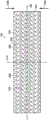
fig. 3 is a plan view of an example of a contact layer that may be associated with some embodiments of the dressing;
FIG. 4 is a detailed view of the contact layer of FIG. 3, illustrating additional details that may be associated with some embodiments;
FIG. 5 is another detailed view of a portion of the contact layer of FIG. 3, illustrating additional details that may be associated with some embodiments;
fig. 6 is a schematic diagram of an example of a therapy system 100, illustrating additional details that may be associated with some embodiments;
FIG. 7 is a plan view of the contact layer of FIG. 3 collapsed under negative pressure;
FIG. 8 is a detailed view of the treatment system of FIG. 6, illustrating additional details that may be associated with some embodiments of the contact layer and optional filler;
FIG. 9 is a plan view of another example of a contact layer, illustrating additional details that may be associated with some embodiments;
FIG. 10 is a plan view of another example of a contact layer, illustrating additional details that may be associated with some embodiments;
FIG. 11 is a plan view of another example of a contact layer, illustrating additional details that may be associated with some embodiments;
fig. 12 is a flowchart illustrating exemplary operations that may be associated with some embodiments of the therapy system of fig. 1; and
fig. 13 is a flow chart illustrating exemplary operations that may be associated with some embodiments of the therapy system of fig. 1.
Figure 14a is a photograph of the first surface of dressing 1 of example 1.
Figure 14b is a photograph of the second surface of dressing 1 of example 1.
Fig. 14c is a photograph of a side view of the dressing 1 of example 1.
Fig. 14d is a photograph of the first surface of dressing 1 of example 1 after two instillation cycles and two Negative Pressure Wound Therapy (NPWT) cycles.
Fig. 15a and 15b are photographs of the first surface of an exemplary dressing 1 prior to the instillation cycle and the NPWT cycle.
Fig. 15c is a photograph of the first surface of the example dressing 1 after the first drip cycle.
Fig. 15d is a photograph of the first surface of the example dressing 1 after a first NPWT cycle.
Fig. 15e is a photograph of the first surface of the example dressing 1 after a second instillation cycle.
Fig. 15f is a photograph of the first surface of the example dressing 1 after a second NPWT cycle.
Figure 16a is a series of photographs of simulated eschar at time zero (T0) with Phosphate Buffered Saline (PBS) and the following four debridement solutions (1% bromelain, 1% papain, 1% collagenase, and 1% trypsin).
Figure 16b is a series of photographs of simulated eschar applied with PBS and the following four debridement solutions (1% bromelain, 1% papain, 1% collagenase and 1% trypsin) at two hours (T2).
Figure 16c is a series of photographs of simulated eschar applied at four hours (T4) with PBS and the following four debridement solutions (1% bromelain, 1% papain, 1% collagenase, and 1% trypsin).
Detailed Description
The following description of exemplary embodiments provides information that enables one of ordinary skill in the art to make and use the subject matter recited in the appended claims, but may omit certain details that are already known in the art. The following detailed description is, therefore, to be regarded as illustrative rather than restrictive.
The exemplary embodiments may also be described herein with reference to the spatial relationships between different elements or the spatial orientations of different elements depicted in the figures. In general, such a relationship or orientation assumes a frame of reference that is consistent with or relative to a patient in a position to be treated. However, those skilled in the art will recognize that this frame of reference is merely a descriptive expedient and is not strictly necessary.
I. Treatment system
Fig. 1 is a simplified functional block diagram of an exemplary embodiment of a treatment system 100 that can provide negative pressure treatment to a tissue site and local instillation of a treatment solution in accordance with the present description.
In this context, the term "tissue site" broadly refers to a wound, defect, or other therapeutic target located on or within a tissue, including but not limited to bone tissue, adipose tissue, muscle tissue, neural tissue, skin tissue, vascular tissue, connective tissue, cartilage, tendons, or ligaments. Wounds may include, for example, chronic, acute, traumatic, subacute, and dehiscent wounds, partial cortical burns, ulcers (such as diabetic ulcers, pressure ulcers, or venous insufficiency ulcers), flaps, and grafts. The term "tissue site" may also refer to any area of tissue that is not necessarily wounded or defective, but rather an area in which it may be desirable to increase or facilitate the growth of additional tissue. For example, negative pressure may be applied to the tissue site to grow additional tissue that may be harvested and transplanted.
For example, therapy system 100 may include a negative pressure source or source (such as negative pressure source 105), a wound dressing 110, a fluid container (such as container 115), and a regulator or controller (such as controller 120). In addition, the therapy system 100 may include sensors for measuring operating parameters and providing feedback signals indicative of the operating parameters to the controller 120. For example, as shown in fig. 1, treatment system 100 may include a pressure sensor 125 coupled to controller 120, an electrical sensor 130, or both. As illustrated in the example of fig. 1, wound dressing 110 may include or consist essentially of one or more of debridement matrix 135, contact layer 140, and optionally cover 145.
The treatment system 100 may also include an instillation solution source. For example, the solution source 150 may be fluidly coupled to the wound dressing 110, as illustrated in the exemplary embodiment of fig. 1. In some embodiments, solution source 150 may be fluidly coupled to a positive pressure source (such as positive pressure source 155), a negative pressure source (such as negative pressure source 105), or both. A regulator, such as an instillation regulator 160, may also be fluidly coupled to the solution source 150 and the wound dressing 110 to ensure proper administration of instillation solution (e.g., saline) to the tissue site. For example, the instillation regulator 160 may include a piston that may be pneumatically actuated by the negative pressure source 105 to draw instillation solution from the solution source during the negative pressure interval and instill the solution to the wound dressing during the ventilation interval. Additionally or alternatively, the controller 120 can be coupled to the negative pressure source 105, the positive pressure source 155, or both, to control administration of the instillation solution to the tissue site. In some embodiments, the instillation regulator 160 may also be fluidly coupled to the negative pressure source 105 through the wound dressing 110, as illustrated by example in fig. 1.
Some components of treatment system 100 may be housed within or used in conjunction with other components, such as sensors, processing units, alarm indicators, memory, databases, software, display devices, or user interfaces that further facilitate treatment. For example, in some embodiments, the negative pressure source 105 may be combined with the solution source 150, the controller 120, and other components into a therapy unit.
In general, the components of treatment system 100 may be coupled directly or indirectly. For example, negative pressure source 105 may be coupled directly to container 115, and may be coupled indirectly to wound dressing 110 through container 115. In some cases, coupling may include fluidic coupling, mechanical coupling, thermal coupling, electrical coupling, or chemical coupling (such as a chemical bond), or some combination of couplings. For example, the negative pressure source 105 may be electrically coupled to the controller 120 and may be fluidly coupled to one or more distribution members to provide a fluid path to the tissue site. In some embodiments, the components may also be coupled by means of physical proximity, integral with a unitary structure, or formed from the same piece of material.
The distribution member is preferably removable and may be disposable, reusable or recyclable. Wound dressing 110 and container 115 are illustrations of distributed components. A fluid conductor is another illustrative example of a distribution member. In this context, a "fluid conductor" broadly includes a tube, pipe, hose, conduit, or other structure having one or more lumens or open passages adapted to convey fluid between two ends. Typically, the tube is an elongated cylindrical structure with some flexibility, but the geometry and rigidity may vary. Further, some fluid conductors may be molded into or otherwise integrally combined with other components. The distribution component may also contain or include interfaces or fluid ports to facilitate coupling and decoupling of other components. In some embodiments, for example, the wound dressing interface may facilitate coupling the fluid conductor to the wound dressing 110. For example, such a wound dressing interface may be sensat r.a.c. available from KCI corporation of San Antonio, Texas.TMA liner.
A. Negative pressure supply source
For example, the negative pressure supply source (such as negative pressure source 105) may be an air reservoir under negative pressure, or may be a manual or electric device, such as a vacuum pump, suction pump, wall mounted suction port available in many healthcare facilities, or a micro-pump. "negative pressure" generally refers to a pressure less than the local ambient pressure, which is the ambient pressure in the local environment, such as outside the sealed treatment environment. In many cases, the local ambient pressure may also be the atmospheric pressure at the location of the tissue site. Alternatively, the pressure may be less than a hydrostatic pressure associated with tissue at the tissue site. Unless otherwise stated, the values of pressure stated herein are gauge pressures. Reference to an increase in negative pressure generally refers to a decrease in absolute pressure, while a decrease in negative pressure generally refers to an increase in absolute pressure. While the amount and nature of the negative pressure applied to the tissue site may vary depending on the treatment requirements, the pressure is generally a low vacuum, also commonly referred to as a rough vacuum, between-5 mm Hg (-667Pa) and-500 mm Hg (-66.7 kPa). A typical treatment range is between-50 mm Hg (-6.7kPa) and-300 mm Hg (-39.9 kPa).
B. Container with a lid
The container 115 represents a container, canister, pouch, or other storage component that may be used to manage exudates and other fluids drawn from the tissue site. In many environments, a rigid container may be preferable or desirable for collecting, storing, and disposing of fluids. In other environments, the fluid may be properly disposed of without the need for rigid container storage, and the reusable container may reduce waste and costs associated with negative pressure therapy.
C. Controller
The controller (such as controller 120) may be a microprocessor or computer programmed to operate one or more components of the treatment system 100 (such as the negative pressure source 105). In some embodiments, for example, controller 120 may be a microcontroller that generally includes an integrated circuit including a processor core and memory programmed to directly or indirectly control one or more operating parameters of treatment system 100. For example, the operating parameters may include power applied to negative pressure source 105, pressure generated by negative pressure source 105, or pressure distributed to contact layer 140. The controller 120 is also preferably configured to receive one or more input signals (such as feedback signals) and is programmed to modify one or more operating parameters based on the input signals.
D. Sensor with a sensor element
A sensor, such as pressure sensor 125 or electrical sensor 130, is generally considered in the art to be any device operable to detect or measure a physical phenomenon or characteristic, and generally provides a signal indicative of the detected or measured phenomenon or characteristic. For example, pressure sensor 125 and electrical sensor 130 may be configured to measure one or more operating parameters of treatment system 100. In some embodiments, the pressure sensor 125 may be a transducer configured to measure the pressure in the pneumatic circuit and convert the measurement into a signal indicative of the measured pressure. In some embodiments, for example, the pressure sensor 125 may be a piezoresistive strain gauge. In some embodiments, electrical sensor 130 may optionally measure an operating parameter of negative pressure source 105, such as voltage or current. Preferably, the signals from pressure sensor 125 and electrical sensor 130 are suitable as input signals to controller 120, but in some embodiments, it may be suitable to make some signal adjustments. For example, the signal may need to be filtered or amplified before being processed by the controller 120. Typically, the signals are electrical signals, but may be represented in other forms, such as optical signals.
E. Wound dressing
A wound dressing, such as wound dressing 110, may be of any suitable configuration and composition. In some embodiments, wound dressing 110 may include a contact layer 140 and a debriding matrix 135. In some embodiments, debridement matrix 135 may be operably coupled to contact layer 140.
1. Contact layer
The contact layer 140 may generally be adapted to partially or fully contact the tissue site. The contact layer 140 may take many forms and may have many sizes, shapes, or thicknesses depending on a variety of factors, such as the type of treatment being performed or the nature and size of the tissue site. For example, the size and shape of the contact layer 140 may be adapted to the contours of a deep and irregularly shaped tissue site. Further, any or all surfaces of the contact layer 140 may have protrusions or uneven, rough, or jagged contours that may cause strain and stress at the tissue site, which may promote granulation growth at the tissue site.
In some embodiments, the contact layer 140 may be formed by a manifold. In this context, a "manifold" generally includes any substance or structure that provides a plurality of pathways adapted to collect or distribute fluid under pressure over a tissue site. For example, the manifold may be adapted to receive negative pressure from the source and distribute the negative pressure across the tissue site through the plurality of apertures, which may have the effect of collecting fluid from the tissue site and drawing the fluid toward the source. In some embodiments, the fluid path may be reversed, or an auxiliary fluid path may be provided to facilitate delivery of fluid (such as fluid from an instillation solution source) onto the tissue site.
In some illustrative embodiments, the passageways of the manifold may be interconnected in order to improve distribution or collection of fluid over the tissue site. In some illustrative embodiments, the manifold may be a porous material having interconnected cells or pores. For example, cellular foams, open-cell foams, reticulated foams, porous tissue aggregates, and other porous materials such as gauze or felted mats, typically include pores, edges, and/or walls adapted to form interconnected fluid channels. Liquids, gels, and other foams may also include or be cured to include pores and fluid pathways. In other embodiments, perforated closed cell foams may be suitable. For example, some embodiments of the contact layer 140 may include or consist of closed cell, cross-linked polyolefin foam with perforations. In some embodiments, the manifold may additionally or alternatively include a protrusion forming an interconnecting fluid passage. For example, the manifold may be molded to provide surface protrusions defining interconnected fluid passages.
The average cell size of the foam may vary according to the needs of the prescribed treatment. For example,in some embodiments, the contact layer 140 may be a foam having a pore size in the range of 400 microns to 600 microns. The tensile strength of the contact layer 140 may also vary according to the needs of the prescribed treatment. For example, the tensile strength of the foam may be increased to instill a topical treatment solution. In some examples, the contact layer 140 may be a GRANUFOAM such as available from KCI corporation of San Antonio, TexasTMDressing or v.a.c.veraf L OTMReticulated polyurethane foam found in dressings.
In some embodiments, the contact layer 140 may be formed of: the material is mechanically or chemically compressed to increase the density at ambient pressure. For example, the contact layer 140 may include or be composed of a compressible material, such as compressed foam. Compressed foams can be characterized by a hardness coefficient defined as the ratio of the density of the foam in a compressed state to the density of the same foam in an uncompressed state. In some embodiments, the contact layer 140 may have a hardness coefficient of about 1 to about 10. For example, a compressed foam having a density five times greater than the density of the same foam in an uncompressed state can be characterized as having a hardness coefficient of 5. Increasing the stiffness coefficient of the foam may increase the stiffness of the foam in a direction parallel to the thickness of the foam. For example, increasing the stiffness coefficient of the contact layer 140 may increase the stiffness of the contact layer 140 in a direction parallel to the thickness of the contact layer 140. In some embodiments, the contact layer 140 may include or be composed of compressed reticulated polyurethane foam, and may have a density of about 0.03 grams/centimeter 3(g/cm3) in its uncompressed state. If the foam is compressed to a durometer of 5, the foam may be compressed until the foam has a density of about 0.15g/cm 3. In some embodiments, the contact layer 140 may comprise or consist of a compressed foam having a thickness of between about 4 millimeters and about 15 millimeters, more specifically about 8 millimeters, at ambient pressure.
In general, compressed foams exhibit less deformation under negative pressure than similar uncompressed foams. The reduction in deformation may be caused by increased stiffness as reflected by the stiffness coefficient. If subjected to negative pressure stresses, compressed foam may be flatter than uncompressed foam of similar material. In some examples, if the thickness of the contact layer 140 is about 8 millimeters at ambient pressure, the thickness of the contact layer 140 may be between about 1 millimeter and about 5 millimeters, and typically greater than about 3 millimeters, at therapeutic levels of negative pressure. The stiffness of the compressed foam in a direction parallel to the thickness of the foam may allow the foam to be more compliant or compressible in other directions, such as in a direction perpendicular to the thickness.
The contact layer 140 may be hydrophobic or hydrophilic. In examples where the contact layer 140 may be hydrophilic, the contact layer 140 may also wick fluid from the tissue site while continuing to distribute negative pressure to the tissue site. The wicking properties of the contact layer 140 may draw fluid away from the tissue site via capillary flow or other wicking mechanisms. An example of a hydrophilic foam is a polyvinyl alcohol open-cell foam such as V.A.C. WHITEFOAM available from KCI corporation of San Antonio, TexasTMA dressing is provided. Other hydrophilic foams may include hydrophilic foams made from polyethers. Other foams that may exhibit hydrophilic characteristics include hydrophobic foams that have been treated or coated to provide hydrophilicity.
When the pressure within the sealed treatment environment is reduced, the contact layer 140 may further promote granulation at the tissue site. For example, any or all surfaces of the contact layer 140 may have uneven, rough, or jagged contours that may cause microstrains and stresses at the tissue site if negative pressure is applied through the contact layer 140.
As used herein, the term "resorbable" or "bioabsorbable" is synonymous and refers to the ability of at least a portion of a material to break down, degrade, or dissolve upon contact with physiological fluids or processes such that at least a portion of the material may be absorbed or assimilated at or within a tissue site, e.g., in a mammalian body.
In some embodiments, the contact layer 140 may be formed of a thermoplastic elastomer (TPE), such as a styrene-ethylene-butylene-styrene (SEBS) copolymer or a Thermoplastic Polyurethane (TPU), the contact layer 140 may be formed by combining sheets of TPE or TPU, in some embodiments, the sheets of TPE or TPU may be bonded, welded, adhered, or otherwise coupled to each other, for example, in some embodiments, the sheets of TPE or TPU may be welded using radiant heat, radio frequency welding, or laser welding, percoat, hexacoat, hercule (Hexcel Corp.), and Econocorp may produce suitable sheets of TPE or TPU for forming the contact layer 140. in some embodiments, sheets of TPE or TPU having a thickness between about 0.2mm and about 2.0mm may be used to form a structure suitable for the contact layer 140. in some embodiments, the contact layer 140 may be formed of a 3D fabric (also referred to as spacer fabric.) suitable 3D Fabrics may be formed of heschel (also referred to as spacer fabric), or fabric, fakeltex (r) and texatex fabric, or other beneficial metals such as silver, or silver.
Fig. 2 is a schematic cross-sectional view of an example of wound dressing 110 (including an example of debriding matrix 135 and an example of contact layer 140), illustrating additional details that may be associated with some embodiments.
In some embodiments, the contact layer 140 may have a substantially uniform thickness. A thickness between about 5.0mm to about 20mm or about 5.0mm to about 20mm may be suitable for some configurations. For example, some embodiments of the contact layer 140 may have a thickness of about 8 millimeters. In some embodiments, the thickness may not be strictly uniform. For example, a tolerance of about 2 millimeters may be suitable for some embodiments.
In some embodiments, the contact layer 140 may have one or more perforations 205. In general, the perforations 205 may extend through the contact layer 140. As shown in fig. 2, for example, the one or more perforations 205 may be through-holes extending from the first surface 210 through the contact layer 140 to the second surface 215.
In other embodiments, one or more of the perforations 205 may be blind holes that do not pass completely through the contact layer 140. For example, one or more of the perforations may extend from the first surface 210 into the contact layer 140 and have a depth that is less than the thickness of the contact layer 140.
The perforations 205 may form walls 220 in the contact layer 140. In some embodiments, the inner surface of the wall 220 may be substantially perpendicular to the first surface 210 and the second surface 215 of the contact layer 140. In still other embodiments, the wall 220 may have a substantially smooth surface between the first surface 210 and the second surface 215 of the contact layer 140. In still other embodiments, the perforations 205 may be tapered and may have a conical, pyramidal, or other irregular geometry. In some embodiments, the perforations 205 may be formed such that a central axis of each perforation 205 is orthogonal to the first surface 210, the second surface 215, or both. In other embodiments, one or more of the perforations 205 may be formed such that the central axis is oblique relative to the first surface 210, the second surface 215, or both.
Fig. 3 is a plan view of an example of a contact layer 140, illustrating additional details that may be associated with some embodiments. For example, some embodiments of the perforations 205 may have a circular cross-section, as shown in FIG. 3. In some embodiments, the perforations 205 may have an average diameter of greater than about 2.0mm, greater than about 4.0mm, greater than about 6.0mm, greater than about 10mm, or between about 5mm and about 20mm, and in some embodiments, the average diameter of the perforations 205 may be about 10 mm.
In some embodiments, the contact layer 140 may have a first alignment line 305 and a second alignment line 310 perpendicular to the first alignment line 305. The first and second alignment lines 305 and 310 may be lines of symmetry passing through the contact layer 140. In the example of fig. 3, the contact layer 140 has a generally rectangular shape, with longitudinal edges 315 and lateral edges 320. In some embodiments, first orientation line 305 may be parallel to longitudinal edge 315.
In some embodiments, the longitudinal edges 315 and the lateral edges 320 of the contact layer 140 may not be straight edges. For example, one or more of the perforations 205 may overlie the longitudinal edges 315 or the transverse edges 320, thereby causing the edges to have a non-linear profile, which may reduce disruption of keratinocyte migration and enhance re-epithelialization when negative pressure is applied to the wound dressing 110.
The contact layer 140 may also have a variety of other suitable shapes. For example, the contact layer 140 may have a diamond, square, or circular shape. In some embodiments, the shape of the contact layer 140 may be selected to accommodate the shape or type of tissue site. For example, the contact layer 140 may have an elliptical or circular shape to accommodate oval or circular tissue sites.
Fig. 4 is a detailed view of one of the perforations 205 of fig. 3, illustrating additional details that may be associated with some embodiments. As illustrated in the example of fig. 4, one or more of the perforations 205 may include a center 405 and a periphery 410. Each of the perforations 205 may also be characterized by a shape factor. The shape factor may represent the orientation of each of the perforations 205 relative to the first orientation line 305 and the second orientation line 310. In general, the form factor is the ratio of the 1/2 largest dimension parallel to the desired collapse direction to the 1/2 largest dimension perpendicular to the desired collapse direction. For example, the desired direction of contraction in fig. 4 may be parallel to second orientation line 310, as indicated by vector 415. First axis 420 may pass through center 405 parallel to first orientation line 305 and second axis 425 may pass through center 405 parallel to second orientation line 310. The shape factor of each of the perforations 205 may be defined as a ratio of a first line segment 430 extending from the center 405 to the perimeter 410 on the second axis 425 to a second line segment 435 extending from the center 405 to the perimeter 410 on the first axis 420. For example, if the length of the first line segment 430 is 2.5mm and the length of the second line segment 435 is 2.5mm, the form factor would be 1. In other embodiments, perforations 205 may have other shapes and orientations, such as oval, hexagonal, elliptical, circular, square, triangular, conical, or amorphous or irregular, or combinations thereof, and may be oriented relative to first orientation line 305 and second orientation line 310 such that the form factor may be in the range of about 0.5 to about 1.10.
Fig. 5 is a detailed view of a portion of the perforation 205 of fig. 3, illustrating additional details that may be associated with some embodiments. In some embodiments, the perforations 205 may be aligned in parallel rows, e.g., two or more parallel rows, to form an array, as illustrated in the example of fig. 5. For example, the array of perforations 205 may include a first row 505, a second row 510, and a third row 515. In some embodiments, the width of the wall 220 between the perimeters 410 of two or more of the perforations 205 in a row (such as the first row 505) may be about 5 millimeters. The center 405 of each of the perforations 205 in adjacent rows (e.g., first row 505 and second row 510) can be characterized as being offset along the first orientation line 305. In some embodiments, strut lines 520 passing through the center 405 of each of the perforations 205 in adjacent rows may define strut angles 525 with the first orientation line 305. In some embodiments, the strut angle 525 may be less than about 90 °. In other embodiments, the strut angle 525 may be between about 30 ° and about 70 °. In other embodiments, the strut angle 525 may be about 66 °. In general, as the pillar angle 525 decreases, the stiffness of the contact layer 140 in a direction parallel to the first orientation line 305 may increase. Increasing the stiffness of the contact layer 140 parallel to the first alignment lines 305 may increase the compressibility of the contact layer 140 perpendicular to the first alignment lines 305.
In some embodiments, the center 405 of each of the perforations 205 in alternating rows may be spaced parallel to the second orientation line 310 by a length 530. In some embodiments, length 530 may be greater than the effective diameter of perforations 205. In some embodiments, the length 530 may be between about 7mm and about 25 mm.
The contact layer 140 may additionally or alternatively be characterized by a void space percentage that reflects a ratio of void space in the first surface 210 created by the perforations 205 to an area defined by a perimeter of the contact layer 140. In general, the void space percentage can be designed to achieve a desired balance between processing characteristics and flexibility. For example, increasing the percentage of void space may increase the shrinkage characteristics of the perforations 205 and may also decrease the handling characteristics of the contact layer 140. A void space percentage between about 40% and about 75% may be suitable for some embodiments. For example, some embodiments may have a void space percentage of about 55%.
In some embodiments, the perforations 205 may have an effective diameter of between about 3 millimeters and about 20 millimeters. The effective diameter of the non-circular region is the diameter of the circular region having the same surface area as the non-circular region. In some embodiments, one or more of the perforations 205 have a non-circular cross-section with an effective diameter of about 3.5 mm. In other embodiments, the perforations 205 may have an effective diameter between about 5mm and about 20 mm.
In general, the perforations 205 are not formed by a foaming process and may be distinguished from the pores or cells of the material forming the contact layer 140. For example, individual pores or cells of the material are typically not large enough to extend completely through the contact layer 140. The effective diameter of the perforations 205 may be an order of magnitude greater than the effective diameter of the pores or cells of the material forming the contact layer 140. In some embodiments, the effective diameter of the perforations may be greater than about 1mm, while the material of the contact layer 140 may be a foam having a pore size of less than about 600 microns.
In some embodiments, the perforations 205 may be formed during the molding process of the contact layer 140. In other embodiments, the perforations 205 may be formed by cutting, melting, drilling, or evaporating the contact layer 140 after the contact layer 140 is formed. For example, the vias may be formed by reaming, drilling, or milling holes completely through the contact layer 140. Additionally or alternatively, perforations 205 may be laser cut in the contact layer 140.
In some embodiments, the formation of the perforations 205 may thermoform the material of the contact layer 140, resulting in the inner surface of the perforations 205 being non-porous. For example, laser cutting the perforation 205 into the contact layer 140 may plastically deform the material of the contact layer 140, thereby closing any pores on the inner surface of the perforation 205. Additionally or alternatively, the smooth inner surface of the perforations 205 may be formed by applying or coating a smooth material to the perforations 205. In some embodiments, the smooth inner surface may limit or otherwise inhibit the ingrowth of tissue into the contact layer 140 through the perforations 205.
2. Dressing matrix
As illustrated in the example of fig. 2, in some embodiments, debriding matrix 135 may be disposed adjacent to or adhered to a surface of contact layer 140. For example, debridement matrix 135 may be in the form of a continuous or discontinuous coating, film, gel, layer, and/or sheet that may be adhered, affixed, fastened, or bonded to contact layer 140. In some embodiments, debriding matrix 135 may be a coating on at least a portion of the surface of contact layer 140, for example, debriding matrix 135 may be coated on at least about 10%, at least about 25%, at least about 50%, at least about 75%, or at least about 95% of the surface of contact layer 140. In some embodiments, debriding matrix 135 may be a coating on substantially the entire surface of contact layer 140, for example, debriding matrix 135 may be coated on at least about 99%, 99.9%, or about 100% of the surface of contact layer 140.
In some embodiments, debriding matrix 135 may cover only a portion of perforations 205, and thus at least a portion of perforations 205 may not be covered by debriding matrix 135. In other embodiments, debridement matrix 135 may be a solid sheet covering perforations 205 as illustrated in the example of fig. 2. In other embodiments, debriding matrix 135 may at least partially fill at least a portion of perforations 205, or at least partially fill substantially all of perforations 205. Alternatively, debridement matrix 135 may fill at least a portion of perforations 205 substantially, or fill substantially all of perforations 205. In some embodiments, debriding matrix 135 may be at least partially removable or separable from contact layer 140. For example, debriding matrix 135 may be removed from contact layer 140 and applied directly to a tissue site.
The thickness of debridement matrix 135 may vary. Thicknesses in the range of about 1.0mm to about 10mm, about 1.0mm to about 5.0mm, or about 1.0mm to about 3.0mm may be suitable for some embodiments. In some embodiments, debridement matrix 135 may be porous, or may have perforations, slits, fenestrations, fluid passageways, or other means for fluid flow through debridement matrix 135.
In various embodiments, debriding matrix 135 may include at least one debriding agent and a polymer. In some embodiments, debriding matrix 135 may have a pH of about 2 to about 10 or lower, for example, a pH of about 1.0 to about 6.0, a pH of about 2.0 to about 5.0, or a pH of about 2.5 to about 4.0, wherein lower pH may further aid in wound healing. The debriding agent may be any enzyme capable of debriding a tissue site or wound. As used herein, the term "debridement" or "debridement" refers to softening, weakening, removal, separation, and/or destruction of tissue and/or cells (such as necrotic tissue, biofilm, slough, eschar, and other debris from a tissue site (e.g., a wound), which may promote healing and/or reduce the risk of infection in some embodiments, a debridement agent advantageously may be active (i.e., cause debridement or destruction of tissue) within a broad pH range (e.g., a pH value of about 2 to about 12, or about 2 to about 10) within a tissue site or wound, the debridement agent may be present in different concentrations and/or activities of USP units (USP units), e.g., about 0.25USP units to about 1,000USP units, about 0.25USP units to about 500USP units, about 0.25USP units to about 300USP units, or about 30 units to about 300USP units, in some embodiments, the debriding agent may advantageously be present in higher concentrations and/or USP activity units to enhance debridement. In some embodiments, the debriding agent may be selected from the group consisting of papain, urea, streptokinase, streptococcal deoxyribonuclease, trypsin, collagenase, plasmin, deoxyribonuclease (DNase), plasmin and DNase (plasmin/DNase), bromelain, and combinations thereof.
The polymer may be any suitable organic polymer for immobilizing the debriding agent therein. In addition, the polymer may be biodegradable. As used herein, the term "biodegradable" refers to a material that is capable of degrading or decomposing chemically and/or physically, such as upon contact with a tissue site and/or physiological fluid or process. "biodegradation" includes tearing, rupturing, severing, breaking, dissolving, dissociating, and the like. Terms such as "soluble", "decomposable", "tearable", "rupturable", "severable", "breakable", "destructible", and the like may be used and refer to materials that are capable of biodegradation. Biodegradation may be exhibited as a result of a chemical process or condition, a physical process or condition, or a combination thereof. Examples of suitable polymers include, but are not limited to, polysaccharides (e.g., citrus pectin, malt, starch, agar), proteins (e.g., collagen, gelatin, albumin), vegetable gums (e.g., xanthan gum, locust bean, guar gum), and combinations thereof. Additionally or alternatively, the polymer may be bioabsorbable.
Depending on the solubility desired during use, the polymer may have a soluble solids composition of at least about 10%, such as from about 10% to about 90% or from 10% to about 70%, for example, during a drip cycle. For example, at least about 10% of the polymer is soluble in aqueous solution, e.g., at a pH of about 2 to about 10. The polymer and/or debridement matrix 135 may be biodegradable or dissolvable during use, for example, upon contact with a tissue site to release a debriding agent that may debride the tissue site. Complete biodegradation or dissolution of the polymer is not necessary for debridement to occur at the tissue site. Rather, debridement of a tissue site may occur in one or more of the following situations: when debridement matrix 135 initially contacts the tissue site; upon biodegradation or dissolution of the polymer; once the polymer ceases to biodegrade or dissolve; and after the polymer has substantially biodegraded or dissolved. Following biodegradation or dissolution of the polymer, release of the debriding agent, and/or debridement of the tissue site, the debriding agent and any remaining polymer and any wound debris may advantageously be washed away at desired intervals, for example, between instillation therapy sessions. In some embodiments, the polymer and/or debridement matrix 135 may dissolve at different rates, e.g., fast or slow, as desired. For example, the polymer and/or debridement matrix 135 may dissolve within a few minutes (e.g., 1, 2, 3, 4, 5 minutes, etc.) within one treatment cycle, for example, or the polymer and/or debridement matrix 135 may dissolve over the course of one or more days, e.g., until the end of treatment.
In some embodiments, debriding matrix 135 may further include one or more of varying amounts of a desiccant, a thickening agent, and a slow release agent. Examples of suitable desiccants include, but are not limited to, silica gel (e.g., silica xerogel, silica gel fibers), magnesium aluminum silicate, calcium oxide, calcium sulfate, sulfonates, and combinations thereof. Examples of suitable thickeners include, but are not limited to, glycerin, carbomers, polyethylene glycols, and combinations thereof. Without being bound by theory, it is believed that the desiccant and/or thickener may help to break up, remove or separate wound debris by applying surface drying and/or denaturing effects. Such drying and/or denaturing activities, as well as the mechanical action of the wound dressing, may exhibit a co-or synergistic effect in disrupting, removing, or separating wound debris.
In other embodiments, debriding matrix 135 may further comprise oxidized cellulose. The term "oxidized cellulose" refers to any material produced by oxidation of cellulose, such as with dinitrogen tetroxide. Such oxidation converts primary alcohol groups on the saccharide residues to carboxylic acid groups, forming uronic acid residues within the cellulose chain. Oxidation does not generally proceed with complete selectivity, and therefore the hydroxyl groups on carbons 2 and 3 are occasionally converted to the ketone form. These ketone units introduce basic labile linkages which at pH 7 or higher initiate decomposition of the polymer via cleavage to form lactones and sugar rings. Thus, oxidized cellulose is biodegradable and resorbable or bioabsorbable under physiological conditions. In some embodimentsThe oxidized cellulose present in debridement matrix 135 may be Oxidized Regenerated Cellulose (ORC), which may be prepared by oxidation of regenerated cellulose, such as rayon. ORC is known to have hemostatic properties. ORC has been known since 1950 (Qiangsheng medical Co., Ltd. (Johnson)&Johnson Medical, Inc.). The product may be produced by oxidation of knitted rayon material.
In some embodiments, additional layers or components may be present in the wound dressing. For example, at least one additional layer or component may be present between contact layer 140 and debriding matrix 135, at least one additional layer or component may be present adjacent to a surface of debriding matrix 135 opposite a surface of debriding matrix 135 adjacent to contact layer 140, and/or at least one additional layer or component may be present adjacent to a surface of contact layer 140 opposite a surface of contact layer 140 adjacent to debriding matrix 135.
F. Covering element
Referring again to fig. 1, in some embodiments, a cover 145 may be provided in the wound dressing 110. The cover may provide a bacterial barrier as well as protection against physical trauma. In some embodiments, the cover 145 may also be constructed of a material that can reduce evaporation losses and provide a fluid seal between two components or two environments (such as between a therapeutic environment and a local external environment). The cover 145 may be, for example, an elastomeric film or membrane that may provide a seal sufficient to maintain negative pressure at the tissue site for a given source of negative pressure. In some applications, the cover 145 may have a high Moisture Vapor Transmission Rate (MVTR). For example, in some embodiments, the MVTR may be at least 300g/m every twenty-four hours2. In some exemplary embodiments, the cover 145 may be a water vapor permeable but liquid impermeable polymeric drape, such as a polyurethane film. Such drapes typically have a thickness in the range of 25 to 50 microns. For permeable materials, the permeability should generally be low enough so that the desired negative pressure can be maintained.
G. Attaching device
The cover 145 may be attached to an attachment surface, such as an undamaged skin, a pad, or another cover, using an attachment device. The attachment means may take a variety of forms. For example, the affixion device may be a medically acceptable pressure sensitive adhesive configured to bond the cover 145 to the epidermis surrounding the tissue site. In some embodiments, for example, a portion or all of the cover 145 may be coated with an adhesive, such as an acrylic adhesive, which may have a coat weight of between 25 to 65 grams per square meter (g.s.m). In some embodiments, a thicker adhesive or combination of adhesives may be applied to improve sealing and reduce leakage. Other exemplary embodiments of the attachment device may include double-sided tape, paste, hydrocolloid, hydrogel, silicone gel, or organogel.
H. Solution source
The solution source 150 may also represent a container, tank, pouch, bag, or other storage means that can provide a solution for instillation therapy. The composition of the solution may vary according to the prescribed treatment, but examples of solutions that may be suitable for some prescriptions include hypochlorite-based solutions, silver nitrate (0.5%), sulfur-based solutions, biguanides, cationic solutions, and isotonic solutions.
Methods of use
Methods of using the wound dressings and systems described herein are provided to debride tissue to aid in wound healing.
In some embodiments, a method for debriding a tissue site is provided. As described herein, the method may include positioning a wound dressing layer adjacent to a tissue site. The debriding matrix and the contact layer may be positioned separately or together such that the debriding matrix may be adjacent to the tissue site and the contact layer may be adjacent to the debriding matrix. For example, a separated debridement matrix or a debridement matrix that has been separated (e.g., peeled) from a contact layer may be positioned adjacent to a tissue site, and then the contact layer may be positioned adjacent to the debridement matrix. Alternatively, the wound dressing may be positioned adjacent to the site, wherein the debriding matrix is operably coupled to the contact layer. In other embodiments, the wound dressing (e.g., contact layer and/or debriding matrix) optionally may be customized prior to positioning adjacent the tissue site. Customization may include cutting and/or sizing the wound dressing as desired for the tissue site. For example, the contact layer and debridement matrix may be customized separately or together as desired and then positioned on the tissue site. Once positioned adjacent the tissue site, at least a portion of the debridement matrix may biodegrade or dissolve, and biodegradation or dissolution continues throughout the method. In some embodiments, substantially all of the debridement matrix may biodegrade or dissolve during the method.
In some embodiments, the method may further comprise positioning a sealing member (e.g., a cover) over the wound dressing. In some embodiments, the filler may optionally be positioned above or near the contact layer such that the filler may be disposed between the cover and the contact layer. Additionally, the method may further include sealing the cover to the tissue site, e.g., tissue surrounding the tissue site, to form a sealed environment enclosing the wound dressing. Negative pressure may be supplied to the wound dressing during the method, for example, to draw tissue into perforations present in the contact layer to form nodules.
In some embodiments, instillation therapy may be combined with negative pressure therapy. In some embodiments, the method may further include fluidly coupling a solution source to the sealed environment and providing a fluid to the sealed environment. For example, after a period of supplying negative pressure, fluid may be supplied to the sealed environment from a solution source. In some embodiments, the method may further comprise removing the fluid from the sealed environment. The removed fluid may include one or more of at least a portion of the one or more debriding agents, at least a portion of the polymer, and at least a portion of any other components of the debridement matrix, such as a thickening agent and/or a desiccant.
Fig. 6 is a schematic diagram of an example of treatment system 100, illustrating additional details that may be associated with some methods of using treatment system 100. In operation, debriding matrix 135, contact layer 140, or both may be placed within, over, on, or otherwise in close proximity to tissue site 605. The tissue site 605 may, for example, extend through the epidermis 610, the dermis 615, and into a portion of the subcutaneous tissue 620. In the example of fig. 6, debridement matrix 135 is positioned adjacent to tissue site 605, and contact layer 140 is disposed adjacent to debridement matrix 135. As shown in fig. 7, first alignment lines 305 and second alignment lines 310 may be used to orient a desired shrinkage direction of the contact layer 140. For example, the desired direction of contraction may be parallel to the second orientation line 310 and perpendicular to the first orientation line 305. In other embodiments, the desired direction of contraction may be parallel to the first orientation line 305 and perpendicular to the second orientation line 310. In still other embodiments, the desired direction of contraction may be at an oblique angle to the first orientation line 305 and the second orientation line 310. In other embodiments, the contact layer 140 may not have a desired direction of shrinkage. Optionally, a filler 625 may also be disposed adjacent to the contact layer 140, which may be useful for deep wounds. The filler 625 may be a manifold, such as reticulated foam. Cover 145 may be placed over debridement matrix 135 and contact layer 140 and may be sealed to the apposition surface near tissue site 605. For example, the cover 145 may seal to tissue surrounding the tissue site 605, such as undamaged epidermis surrounding the tissue site 605. Thus, the wound dressing 110 may provide a sealed environment 630 substantially isolated from the external environment near the tissue site 605.
The negative pressure source 105 may be fluidly coupled to the sealed environment 630 between the cover 145 and the tissue site 605. As illustrated in the example of fig. 6, in some embodiments, the negative pressure source 105 may be fluidly coupled to the contact layer 140 by a first fluid conductor 635 and a first dressing interface 640. The negative pressure source 105 may reduce the pressure in the sealed treatment environment. The negative pressure applied on the tissue site 605 through the contact layer 140 in the sealed therapeutic environment may induce macroscopic and microscopic strains in the tissue site 605 and remove contact layer polymers, at least one debridement agent, debris, exudates, and other fluids from the tissue site 605, which may be collected in the container 115.
The hydrodynamics of using a negative pressure source to reduce pressure in another component or location, such as within a sealed treatment environment, can be mathematically complex. However, the rationale for hydrodynamics applicable to negative pressure therapy and instillation is generally well known to those skilled in the art, and the process of reducing pressure can be illustratively described herein as, for example, "delivering," "distributing," or "generating" negative pressure.
Generally, exudates and other fluids flow along the fluid path toward lower pressures. Thus, the term "downstream" generally implies a location in the fluid path that is relatively closer to the negative pressure source or further from the positive pressure source. Conversely, the term "upstream" implies a relatively further distance from the negative pressure source or closer to the positive pressure source. Similarly, it may be convenient to describe certain features in this frame of reference in terms of fluid "inlets" or "outlets". This orientation is generally assumed to describe the different features and components herein. However, the fluid path may also be reversed in some applications (such as by replacing the negative pressure source with a positive pressure source), and this descriptive convention should not be construed as a limiting convention.
In some embodiments, the method may include providing cyclical therapy, such as alternately applying and venting negative pressure in the sealed environment 630 via the therapy system 100. Accordingly, in some embodiments, the method may further comprise venting the sealed environment 630. In some embodiments, negative pressure may be supplied to the sealed environment 630 until the pressure in the sealed environment 630 reaches a predetermined therapeutic pressure. The negative pressure may be supplied to the sealed environment 630 for any suitable amount of time (e.g., at least about 10 minutes, at least about 30 minutes, or less than about 60 minutes).
In some embodiments, negative pressure may be delivered to tissue site 605 through contact layer 140 or through contact layer 140 and debridement matrix 135. For example, debridement matrix 135 may be porous, or may have perforations, slits, fenestrations, or other fluid pathways through which fluid may be delivered to tissue site 605. Additionally or alternatively, debridement matrix 135 may be at least partially biodegradable or dissolvable by one or more of exudate, instillation solution, and negative pressure, which may create a fluid pathway.
In some embodiments, the sealed environment 630 may be maintained at the treatment pressure for a predetermined treatment period, such as about 10 minutes, about 30 minutes, or less than about 60 minutes. In other embodiments, the treatment period may be longer or shorter as needed to supply the appropriate negative pressure treatment to the tissue site 605.
After the treatment period, the treatment system 100 may ventilate the environment 630. For example, the treatment system 100 may fluidly couple the sealed environment 630 to the atmosphere, allowing the sealed environment 630 to return to ambient pressure. In some embodiments, for example, by maintaining the sealed environment at ambient pressure, treatment system 100 may ventilate sealed environment 630 for about 1 minute. In other embodiments, the treatment system 100 may ventilate the sealed environment 630 for longer or shorter periods of time. After venting the sealed environment 630, the negative pressure source 105 may begin another negative pressure treatment cycle. In some embodiments, the negative pressure may be supplied to the sealed environment 630 for about 1 minute, and the sealed environment may be vented for about 1 minute.
In some embodiments, instillation therapy may be combined with negative pressure therapy. For example, in some embodiments, the solution source 150 may be fluidly coupled to the contact layer 140 through the second fluid-conducting element 645 and the second dressing interface 650. After the negative pressure treatment period, the treatment system 100 may operate the solution source 150 to provide fluid to the sealed environment 630. In some embodiments, the solution source 150 may provide fluid while venting the sealed environment 630. In other embodiments, the sealed environment 630 may not be vented, and the negative pressure in the sealed environment 630 may draw instillation fluid from the solution source 150 into the sealed environment 630.
In some embodiments, the solution source 150 may provide a volume of fluid to the sealed environment 630. In some embodiments, the fluid volume may be the same as the volume of sealed environment 630. In other embodiments, the fluid volume may be less than or greater than the sealed environment 630. Pouring the solution into the sealed environment 630 may increase the pressure above ambient pressure, for example to between about 0mmHg and about 15mmHg, more specifically about 5 mmHg. In some embodiments, the fluid provided by the solution source 150 may be maintained in the sealed environment 630 for a specified residence time. In some embodiments, the residence time may be about 5 minutes. In other embodiments, the residence time may be longer or shorter, as specified. For example, the residence time may be zero.
At the end of the dwell time, the negative pressure source 105 may be operated to draw the instillation fluid into the container 115 to complete a treatment cycle. As instillation fluid is removed from the sealed environment 630 by the negative pressure, negative pressure may also be applied to the sealed environment 630, thereby initiating another treatment cycle.
In some examples, the tissue site 605 may include debris 655. For example, debris 655 may include one or more of biofilm, necrotic tissue, contused tissue, devitalized tissue, contaminated tissue, damaged tissue, infected tissue, exudate, hyperviscous exudate, and fibrous slough. As shown in fig. 6, the debris 655 may cover all or a portion of the tissue site 605.
The debris 655 may inhibit the efficacy of the tissue treatment and slow healing of the tissue site 605. For example, the biofilm may include a microbial infection, which may cover the tissue site 605 and impair healing of the tissue site 605. The biofilm may also reduce the effectiveness of the topical antimicrobial therapy by preventing the topical therapy from reaching the tissue site 605.
Necrotic tissue may be dead tissue caused by infection, toxin, or trauma that causes the tissue to die faster than tissue that may be removed by normal bodily processes that regulate the removal of dead tissue. Sometimes, the necrotic tissue may be in the form of slough, which may include a viscous liquid tissue mass. In general, slough is produced by bacterial and fungal infections that stimulate inflammatory reactions in tissues. The slough may be cream-colored in color and may also be referred to as pus. Necrotic tissue may also include eschar. The eschar may be a portion of necrotic tissue that has been dehydrated and hardened. Eschar may be the result of burns, gangrene, ulcers, fungal infections, spider bites or anthrax and may be difficult to remove.
Once positioned adjacent to tissue site 605, at least a portion of debriding matrix 135 may biodegrade or dissolve and continue to biodegrade or dissolve, e.g., throughout the instillation and/or negative pressure therapy. The one or more debriding agents may contact the tissue site 605 and advantageously debride at least a portion of the tissue site 605 (including debris 655 present therein), for example, by enzymatic debridement. In some embodiments, the debridement may include only enzymatic debridement.
In some embodiments, debris 655 may be removed, for example, from the surface of the tissue site 605 during dressing change. Advantageously, the time between dressing changes may be increased, for example, by controlling the rate at which the debridement matrix biodegrades or dissolves. For example, the wound dressing may remain adjacent the tissue site for greater than 1 day, greater than 3 days, greater than 5 days, or greater than 7 days prior to dressing change. In some embodiments, the wound dressing may remain adjacent to the tissue for about 1 to 7 days or about 3 to 5 days. In addition, the use of instillation therapy during these intervals between dressing changes may advantageously remove at least a portion of the debriding agent from the tissue site, which may minimize toxicity to the tissue site.
In some embodiments, the cover 145 may be removed from the contact layer 140, and the broken debris 655 may be removed by wiping off the debris 655. In other embodiments, the contact layer 140 may break the debris 655, such that the debris 655 may be removed by negative pressure. In some embodiments, the methods described herein, e.g., using treatment system 100, may be used in conjunction with other tissue removal and debridement techniques. For example, further mechanical and/or enzymatic debridement may be used to remove other portions of the debris 655, e.g., prior to placement of the wound dressing 110 and/or after supply of negative pressure and/or fluid to the tissue site 605. Additionally or alternatively, a sharp debridement may also be used to remove at least a portion of the debris 655, as desired, for example, prior to placement of the wound dressing 110 and/or after supply of negative pressure and/or fluid to the tissue site 605. Sharp debridement may include, but is not limited to, the use of a scalpel, scissors or other sharp instrument in debridement of a tissue site.
In some embodiments, the treatment system 100 may provide mechanical movement and debriding agents in conjunction with negative pressure, instillation solutions, or both to dissolve, debride, and/or remove debris 655. Thus, mechanical and enzymatic debridement may be provided in combination. In some embodiments, the periodic application of the instillation therapy and the negative pressure therapy can cause the contact layer 140 to float and change position relative to the debris 655. For example, negative pressure may be applied to the sealed environment 630 during a negative pressure treatment cycle. After the negative pressure therapy cycle is complete, an instillation fluid may be provided during the instillation therapy cycle. The instillation of the fluid may cause the contact layer 140 to float relative to the debris 655. The positional change may cause the contact layer 140 to engage a slightly different portion of the debris 655 during the next negative pressure therapy cycle, thereby facilitating the destruction of the debris 655.
Additionally or alternatively, in some embodiments, the negative pressure may cause the contact layer 140 to contract, thereby exerting a lateral force on the debris 655. The lateral force may be related to the compressive force generated by applying a negative pressure to the sealed environment 630. For example, the lateral force may be proportional to the product of the Treatment Pressure (TP) in the sealed environment 630, the Compression Factor (CF) of the contact layer 140, and the surface area (a) of the first surface 210 of the contact layer 140. The lateral force may be approximated as the product of TP CF a. In some embodiments, the treatment pressure TP is in N/m2Measured, the Compressibility Factor (CF) is dimensionless, the area (A) is in m2The Compression Factor (CF) resulting from the application of negative pressure to the contact layer 140 may be, for example, a dimensionless number that is proportional to the product of the percent Void Space (VS) of the contact layer 140, the stiffness factor (FF) of the contact layer 140, the Strut Angle (SA) of the contact layer 140, and the Shape Factor (SF) of the perforations 205 in the contact layer 140May result in the actual value of the lateral force being less than the calculated value of the lateral force.
Fig. 7 is a view of contact layer 140 of fig. 3 collapsed under negative pressure, illustrating additional details that may be associated with mechanical disruption of debris 655 in some embodiments. If the contact layer 140 is subjected to negative pressure, the perforations 205 may contract, which may damage the debris 655. For example, the edges of the perforations 205 may form cutting edges that may damage the debris 655. In some embodiments, the cutting edge may be defined by the perimeter 410 of each of the perforations 205. Upon removal of the negative pressure, for example by venting the negative pressure, the contact layer 140 may expand back to the relaxed position. The contact layer 140 may further mechanically break the debris 655 if the contact layer 140 cycles between a contracted position and a relaxed position. In some embodiments, the negative pressure applied by the negative pressure source 105 may be rapidly cycled. For example, negative pressure may be supplied for a few seconds and then vented for a few seconds, causing a negative pressure pulse in the sealed environment 630. The pulsation of the negative pressure may pulse the nodules 805, which may result in further destruction of the debris 655. This contraction of contact layer 140 and perforations 205 in combination with the action of the one or more debriding agents at tissue site 605 may not only advantageously allow for increased debridement at tissue site 605, but may also advantageously result in a co-action or synergy in debriding tissue site 605 and debris 655.
Shrinkage may refer to vertical shrinkage and lateral shrinkage. The material, percentage of void space, perforation shape factor, stiffness factor, size of the perforations 205, and strut angle may influence or control the direction of shrinkage. For example, in some embodiments, one or more of the void space percentage, perforation shape factor, and strut angle may cause the contact layer 140 to shrink along a second orientation line 310 that is perpendicular to the first orientation line 305, as shown in fig. 7. If the contact layer 140 is located on the tissue site 605, the contact layer 140 may contract in a direction 705 toward the first orientation line 305. In some embodiments, the perforations 205 may be circular, the strut angle may be about 37 °, the void space percentage may be about 54%, the stiffness coefficient may be about 5, the shape coefficient may be about 1, and the diameter may be about 5 millimeters. If contact layer 140 is subjected to a negative pressure of about-125 mmHg, contact layer 140 may exert a lateral force of about 11.9N in direction 705. If the diameter of the perforations 205 is increased to about 20 millimeters, the void space percentage is changed to about 52%, the strut angle is changed to about 52 °, and the perforation shape factor and stiffness factor remain unchanged, the lateral force can be reduced to about 6.5N.
Additionally or alternatively, in some embodiments, directing negative pressure in sealed environment 630, for example, through perforations 205, may cause concentrated stress on debris 655 adjacent perforations 205. The force applied to the debris 655 may be a function of the negative pressure supplied to the sealed environment 630 and the cross-sectional area of each of the perforations 205. For example, if the negative pressure is about 125mmHg and the perforations 205 are about 5 millimeters in diameter, the force applied at each of the perforations 205 may be about 0.07 lbs. If the diameter of each of the perforations is increased to about 8 millimeters, the force applied at each of the perforations 205 may be increased by up to 6 times. In general, the relationship between the diameter of each of the perforations 205 and the force applied at each of the perforations 205 is not linear and may increase exponentially as the diameter increases. In some embodiments, healthy tissue adjacent to the tissue site 605 may not be substantially damaged during the method.
Fig. 8 is a detailed view of the treatment system 100 of fig. 6, illustrating additional details that may be associated with the contact layer 140 and optional filler 625 under negative pressure used in the methods described herein. As shown in fig. 8, for example, by directing negative pressure through the perforations 205, the concentrated stress on the debris 655 adjacent the perforations 205 may create macroscopic deformation of the debris 655 and the subcutaneous tissue 620, which may draw the nodules 805 of the subcutaneous tissue 620 having the debris 655 thereon into the perforations 205. In some embodiments, the method may include debriding at least a portion of the debris 655 of the nodule 805. Portions of the filler 625 may also be drawn into the perforations 205 to form the protrusions 810. The protrusion 810 may have a shape corresponding to the shape of the perforation 205. The size of the protrusion 810 may depend on, for example, the magnitude of the negative pressure in the sealed environment 630, the size of the perforations 205, and the stiffness coefficient of the filler 625. At least a portion of debridement matrix 135 that may be at least partially biodegradable or dissolvable may be present adjacent to at least a portion of debris 655.
In some embodiments, supplying a negative force to the sealed environment 630 may create macro-pressure points in the debris 655 and portions of the subcutaneous tissue 620 in contact with the tissue-facing surface of the contact layer 140, resulting in wrinkling of the tissue and nodules 805 in the debris 655 and the subcutaneous tissue 620.
The height of the nodules 805 above the surrounding tissue can be controlled or limited to maximize the destruction of debris 655 and minimize damage to the subcutaneous tissue 620 or other desired tissue. In general, the negative pressure in the sealed environment 630 may exert a force proportional to the area to which the pressure is applied. At the perforations 205, the force may be concentrated because the resistance to the applied pressure is less than the resistance in the walls 220 of the contact layer 140. In response to the force generated by the pressure at the perforation 205, the debris 655 and subcutaneous tissue 620 forming the nodule 805 may be drawn into and through the perforation 205 until the force applied by the pressure is equalized by the reaction forces of the debris 655 and subcutaneous tissue 620. In some embodiments, the thickness 815 of the contact layer 140 may be selected to limit the height of the nodule 805 above the surrounding tissue. Additionally or alternatively, in some embodiments, if the contact layer 140 is compressible, the filler 625 may limit the height of the nodules 805 to the thickness 815 of the contact layer 140 under negative pressure. In other embodiments, the protrusions 810 may limit the height of the nodules 805 to a height that is less than the thickness 815 of the contact layer 140. The coefficient of hardness of the filler 625 may be selected to control the depth of the protrusion 810 into the perforation 205. The height of the nubs 805 may be limited to the difference between the thickness 815 and the height of the projections 810. In some embodiments, the depth of the protrusion 810 may vary from zero to a few millimeters. For example, in some embodiments, the thickness 815 of the contact layer 140 may be about 7 millimeters, and the height of the protrusions 810 may be between about 4 millimeters and about 5 millimeters, thereby limiting the height of the nodules to about 2 millimeters to about 3 millimeters. By controlling the height of the nodules 805, the aggressiveness of the damage and tearing to the debris 655 can be controlled.
In some embodiments, the contact layer 140 may have a first thickness at ambient pressure, and the method may further include compressing the contact layer 140 to a second thickness, which may be less than the first thickness. The nodules 805 can be formed with a height no greater than the second thickness. In some embodiments, the first thickness may be at least about 6mm, at least about 8mm, or about 6mm to about 10 mm. In some embodiments, the second thickness may be at least about 2mm, at least about 3mm, or about 2mm to about 4 mm.
In some embodiments, the height of the nodules 805 may also be controlled by controlling the compressibility of the contact layer 140. For example, if the contact layer 140 is formed of compressed foam, the contact layer 140 may have a higher stiffness coefficient than uncompressed foam. In some embodiments of compressed foam, the thickness 815 of the contact layer 140 may be about 8 millimeters. A negative pressure in sealed environment 630 of between about-50 mmHg and about-350 mmHg, between about-100 mmHg and about-250 mmHg, more specifically about-125 mmHg, may reduce thickness 815 of contact layer 140 from about 8 millimeters to about 3 millimeters. If the filler 625 is placed over the contact layer 140, the height of the nodules 805 may be limited to about 3 millimeters. By controlling the height of the nubs 805, the force applied by the debris 655 can be adjusted and the degree to which the debris 655 is stretched can be varied. In some embodiments, the cyclical application of negative pressure may lift debris 655 and other particles away from the surrounding tissue, operating in a piston-like manner, to move the debris 655 toward the filler 625 and away from the sealed environment 630. In some examples, the application and removal of negative pressure to the sealed environment 630 also ruptures the nodule 805.
In some embodiments, the size of the perforations 205 may be selected to allow the flow of particulates through the perforations 205. In some embodiments, for example, the effective diameter of the perforation 205 may be selected based on the expected size of the dissolved debris to be lifted from the tissue site. The size may also be selected to allow larger debris and to block smaller debris. In some examples, some or all of the debris 655 may be drawn through the perforations 205 and collected in the container 115. Alternatively, the perforations 205 may be different sizes upon successive applications of the wound dressing 110. For example, the size of the perforations 205 may decrease as the size of the debris 655 decreases. The sequentially decreasing size of the perforations 205 may also help to fine tune the level of tissue damage to the debris 655 during treatment of the tissue site 605.
The size of perforations 205 may also affect fluid movement in contact layer 140 and wound dressing 110. For example, the contact layer 140 may direct fluid in the wound dressing 110 toward the perforations 205 to help break debris 655 on the tissue site 605. The change in the size of the perforations 205 may change the manner in which fluid moves through the wound dressing 110 relative to both the removal of fluid and the application of negative pressure.
The shape of the perforations 205 may be varied in different embodiments of the contact layer 140 to vary the concentration of stress. For example, fig. 9 is a plan view of another embodiment of contact layer 140, showing additional details in which perforations 205 have a hexagonal cross-section and lateral forces 905. In the example of fig. 9, the stress on the debris 655 may be concentrated at the apex of the perforation 205. Suitable characteristics of the contact layer 140 of fig. 9 may include a pillar angle of about 66 °, a void space percentage of about 55%, a stiffness coefficient of about 5, a perforation shape coefficient of about 1.07, and an effective diameter of about 5 millimeters. If the contact layer 140 of fig. 9 is subjected to a negative pressure of about-125 mmHg, the lateral force 905 of the contact layer 140 may be about 13.3N. If the effective diameter of the perforation 205 is increased to 10 millimeters, the lateral force 905 may be reduced to about 7.5N. Fig. 10 is a plan view of another example of a contact layer 140, illustrating additional detail in which perforations 205 have an elliptical or oval cross-section and a transverse force 1005. Fig. 11 is a plan view of another example of a contact layer 140, showing additional detail in which the perforations 205 have a triangular cross-section and a lateral force 1105.
Fig. 12 is a flowchart illustrating exemplary operations that may be associated with some embodiments of treatment system 100. One or more operations may be implemented by a controller (such as controller 120) configured to perform the operations. At block 1205, a wound dressing 110 including a contact layer 140 and/or a debriding matrix 135 may be selected for use on the tissue site 605. At block 1210, the contact layer 140 and the debriding matrix 135 may be positioned at a tissue site, such as tissue site 605, separately or together. At block 1215, a filler may be selected for use on the tissue site. At block 1220, the selected filler may be positioned over the contact layer 140. For example, a filler 625 may be positioned over the contact layer 140. At block 1225, a cover may be positioned over the filler 625, the contact layer 140, and the tissue site 605, and at block 1230, the cover may be sealed to tissue surrounding the tissue site. For example, the cover 145 may be positioned over the tissue site 605 and sealed to tissue surrounding the tissue site 605.
At block 1235, a source of negative pressure may be fluidly coupled to the sealed space formed by the cover. For example, the negative pressure source 105 may be fluidly coupled to the sealed environment 630 formed by the cover 145. At block 1240, a negative pressure source may supply negative pressure to the sealed space. For example, the controller may actuate the negative pressure source 105 to supply negative pressure to the sealed environment 630 during a negative pressure therapy session.
At block 1245, the controller may determine whether the negative pressure therapy session has ended. For example, the controller of negative pressure source 105 may determine whether a timer started when the negative pressure source is actuated to supply negative pressure has reached a predetermined time. The predetermined time, which may be a time period selected by a user, may be based on an expected timer interval for negative pressure therapy. At block 1245, if the timer has not expired, the method may continue on the no path to block 1240 where the controller of the negative pressure source may continue to supply negative pressure to the sealed space.
At block 1245, if the timer has expired, the method may continue on the yes path to block 1250 where the controller of the negative pressure source may vent the negative pressure in the sealed space to the ambient environment. For example, the controller of the negative pressure source 105 may vent the sealed environment 630 to the ambient environment.
At block 1255, the method determines whether the treatment has ended. For example, the controller of negative pressure source 105 may determine whether a predetermined number of supply and ventilation cycles have been completed. The predetermined number of supply and ventilation cycles may be a standard number of cycles for treatment, or may be a number of cycles input by the user. If the treatment has not ended, the method can continue on the "no" path to block 1240 where the negative pressure source can be operated to supply negative pressure to the sealed space. If treatment has ended, the method may continue on the "yes" path, where the method ends.
Fig. 13 is a flowchart illustrating exemplary operations that may be associated with some embodiments of treatment system 100. One or more operations may be implemented by a controller (such as controller 120) configured to perform the operations. The operation may also be performed by a user, such as a clinician. At block 1305, a user may examine a tissue site. For example, the clinician may examine the tissue site 605.
At block 1310, a status of debris of the tissue site may be determined. For example, the clinician may determine that debris 655 covers the tissue site 605. The status may also include one or more of the following: the thickness of the debris 655, the consistency of the debris 655, the color of the debris 655, and the moisture level of the debris 655. For example, the clinician may determine that the debris 655 at the tissue site 605 may have a thin, thick, flowing, solid, rough, firm, smooth, heavy, or light consistency. The clinician may determine that the debris 655 at the tissue site 605 has a black, red, brown, green, yellow, gray, or other color that is indicative of the infection status of the tissue site 605. The clinician may also evaluate the debris 655 for example for moisture conditions on a scale ranging from no liquid present to saturation. In some embodiments, the determination of the moisture level may help the clinician understand the amount of exudate present in the tissue site 605.
At block 1315, other parameters that affect the treatment may be evaluated. For example, a clinician may determine a patient's pain tolerance, environment, preferences, age, comorbidities, quality of life, caregiver resources, and caregiver skills.
At block 1320, based on the information determined at blocks 1310 and 1315, a desired target for treating debris at the tissue site may be determined. For example, the clinician may determine whether debris 655 includes necrotic tissue, eschar, damaged tissue, other sources of infection, exudate, slough (including hyperkeratosis), pus, foreign bodies, biofilm, or other types of bioburden. The clinician may also determine whether the treatment will reduce the risk of unpleasant odors, excessive moisture, and infection of the debris 655 and tissue site 605.
At block 1325, a wound dressing including a contact layer and/or a debriding matrix may be selected in response to determining a desired goal for treating debris at the tissue site. For example, a contact layer based on a hardness factor, thickness, via shape, via size, and array pattern to achieve a desired therapeutic goal. For example, the polymer and optional thickening agent, desiccant, and slow release agent may be selected based on the desired dissolution rate of the debridement matrix and the type of wound, wound exudate, and/or bacteria present. For example, one or more debriding agents may be selected based on the wound, wound exudate, and/or the type of bacteria present. For example, the clinician may select a contact layer with cylindrical perforations to allow for the flow of debris 655 having a yellowish color, a thicker consistency, and a high humidity level. The clinician may further select a contact layer having perforations with a diameter greater than the size of the largest dissolved debris in the tissue site. In other embodiments, the clinician may select a contact layer with triangular perforations, for example where the debris is rough, black, and has a low moisture content.
At block 1330, an optional filler may be selected in response to determining a desired target for treating debris at the tissue site. For example, the clinician may select a filler based on the stiffness coefficient and the thickness. In general, the thickness of the filler may be selected to fill the tissue site. The clinician may also select a stiffness coefficient of the filler to limit the height of the nodule 805. For example, if the debris 655 is thinner, has a flowing consistency, and has a smooth surface than the contact layer 140, the clinician may select a filler with a low coefficient of stiffness. The lower durometer filler may allow the protrusion 810 to have a greater height than a filler with a high durometer, thereby reducing the height of the nodule 805. At block 1335, the tissue site may be treated with a wound dressing. For example, a clinician may utilize the contact layer 140 and the treatment system 100 to perform a treatment.
III. kit
In some embodiments, a contact layer (such as contact layer 140) and a debriding substrate (such as debriding substrate 135) may be provided as components of a wound dressing kit, where the contact layer and debriding substrate may be separate or together. In some embodiments, the contact layer may be provided without any perforations (such as perforations 205), and the kit may include a punch that may be used to form perforations in the contact layer. In some embodiments, a debridement matrix may be provided without any perforations. The kit provides a user (such as a clinician) with the ability to customize the contact layer and/or debridement matrix for a particular tissue site such that, for example, the perforations only destroy debris (such as debris 655) without destroying healthy tissue that may be near or surrounding the debris. In some embodiments, the kit may optionally include more or more different sized fillers, for example fillers 625 may be provided. For example, the thickness of the first filler layer may be between about 5 millimeters and about 15 millimeters, and more specifically about 8 millimeters. The thickness of the second filler layer may be between about 10 millimeters and about 20 millimeters, and more specifically about 16 millimeters. One or both of the filling layers may be selected as desired to fill the tissue site.
The systems, devices, methods, and kits described herein may provide significant advantages. For example, combining the mechanical action of the collapsible contact layer with the hydration and irrigation effects of instillation and negative pressure therapy can significantly reduce or eliminate the pain associated with debridement of the tissue site, and can allow for longer time intervals between dressing changes. Wound dressings such as wound dressing 110 may also require less monitoring by a clinician or other attendant than other mechanical and enzymatic debridement methods. In addition, the contact layer 140 is not interrupted by the removed necrotic tissue when performed during autolytic debridement of the tissue site. In addition, contact layer 140 and/or debridement matrix 135 may help remove necrosis, eschar, damaged tissue, sources of infection, exudate, slough (including hyperkeratosis), pus, foreign bodies, debris, and other types of bioburden or healing disorders. Contact layer 140 and/or debridement matrix 135 may also reduce the risk of odor, excess moisture, and infection while stimulating the formation of edges and epithelialization of the tissue site. Some embodiments of wound dressings such as wound dressing 110 may also provide improved removal of thick exudates, allow for earlier placement of instillation and negative pressure therapy devices, may limit or prevent the use of other debridement procedures, and may be used on tissue sites where debridement is difficult to perform.
The contact layer and/or debridement matrix may also be used with other layers or components that are not perforated. For example, the contact layer 140 may be provided and may be cut to fit debris of the tissue site, and other layers or components may be placed over the remaining area of the tissue site. Similarly, other layers or components may be placed between the contact layer and the debriding matrix or between the tissue site and the wound dressing without destruction.
While shown in some illustrative embodiments, one of ordinary skill in the art will appreciate that the systems, apparatus, and methods described herein are susceptible to various changes and modifications as fall within the scope of the appended claims. Moreover, the use of terms such as "or" does not require mutual exclusivity in describing the various alternatives unless the context clearly requires otherwise, and the indefinite article "a" or "an" does not limit the subject matter to a single instance unless the context clearly requires otherwise. Components may also be combined or eliminated in various configurations for purposes of sale, manufacture, assembly, or use. For example, in some configurations, wound dressing 110, container 115, or both may be eliminated or manufactured or sold separately from other components. In other exemplary configurations, the controller 120 may also be manufactured, configured, assembled, or sold independently of other components.
Examples
The benefits associated with the wound dressings, systems, and methods are further demonstrated by the following non-limiting examples. These embodiments may demonstrate one or more features associated with some embodiments of the wound dressings, systems, and methods.
EXAMPLE 1 solubility testing of polysaccharide matrices
A layer of 1mm polysaccharide-based matrix (a mixture of 16 ounces of mature raspberry, 10% pectin in water as a commercial source, mixed and baked until hard) was applied to a foam (V.A.C. VERAF L O C L EANSECHOICE) having perforations thereinTMDressing) contacts a surface of the layer to form a dressing 1 fig. 14a shows a first surface (bottom view) of the dressing 1 having a polysaccharide based matrix layer thereon, wherein the polysaccharide based matrix covers perforations in the foam contact layer fig. 14b shows a second surface (top view) opposite the first surface of the dressing 1 having perforations therein, having a polysaccharide based matrix on the second surface fig. 14c shows a side view of the dressing 1 fig. 1 is contacted over a first instillation cycle (using v.a.c.veraf L O)TMTherapeutic V.A.C.U L TATMTreatment unit) first with saline (1 minute dwell period), then a first NPWT period (3 minute period), then a second drip period with saline, then a second NPWT period. Fig. 15a and 15b show dressing 1 prior to instillation and NPWT cycles. Fig. 15c shows the first surface of the dressing 1 after the first drip cycle. Figure 15d shows the first surface of dressing 1 after the first NPWT cycle. Fig. 15e shows the first surface of the dressing 1 after the second instillation cycle. Figure 15f shows the first surface of dressing 1 after the second NPWT cycle. As shown in FIGS. 15 a-15 f, the polysaccharide-based matrix dissolved from the foam contact layer during treatment was demonstrated by unobstructed perforations
Example 2 comparison of debridement solution on simulated eschar
Four debriding solutions were prepared, 1% bromelain, 1% papain, 1% collagenase and 1% trypsin (enzymes are obtained from commercial sources and dissolved in saline at a concentration of 0.1g/10m L), applied to simulate eschar (charred pigskin), the degree of debridement of the four debriding solutions and PBS was captured via photographs at three different time points, time zero (T0), 2 hours (T2) and 4 hours (T4), fig. 16a, 16b and 16c show the results of the four debriding solutions and PBS for T0, T2 and T4, respectively.
The accompanying claims set forth novel and inventive aspects of the above-described subject matter, but the claims may also encompass additional subject matter that is not explicitly recited. For example, certain features, elements, or aspects may be omitted from the claims if not necessary to distinguish the novel and inventive features from features known to those of ordinary skill in the art. Features, elements, and aspects described in the context of several embodiments may also be omitted, combined, or replaced with alternative features for the same, equivalent, or similar purpose, without departing from the scope of the present invention, which is defined by the following claims.
Claims (67)
1. A wound dressing comprising:
a contact layer comprising walls defining a plurality of perforations; and
a debridement matrix comprising a polymer and at least one debriding agent, wherein the debridement matrix is operably coupled to the contact layer.
2. The wound dressing of claim 1, wherein the debriding matrix is a coating on at least a portion of a surface of the contact layer.
3. The wound dressing of claim 1 or 2, wherein the debriding matrix is a coating on substantially the entire surface of the contact layer.
4. The wound dressing of any one of the preceding claims, wherein at least a portion of the plurality of perforations are not covered by the debriding matrix.
5. The wound dressing of any one of the preceding claims, wherein the debriding matrix is present in at least a portion of the plurality of perforations.
6. The wound dressing of any one of the preceding claims, wherein the debriding matrix is at least partially removable from the contact layer.
7. The wound dressing of any one of the preceding claims, wherein the debriding matrix has a pH of about 2.0 to about 10.
8. The wound dressing of any one of the preceding claims, wherein the debriding matrix is in the form of a film.
9. The wound dressing of any one of the preceding claims, wherein at least about 10% of the debriding matrix is soluble in an aqueous solution having a pH of about 2 to about 10.
10. The wound dressing of any one of the preceding claims, wherein the debriding matrix has a thickness of about 1.0mm to about 10 mm.
11. The wound dressing of any one of the preceding claims, wherein the debriding matrix comprises perforations.
12. The wound dressing of any one of the preceding claims, wherein the debriding agent is active at a pH of about 2 to 12.
13. The wound dressing of any one of the preceding claims, wherein the debriding agent is present in the debridement matrix in an amount from about 0.25USP units to about 1,000USP units.
14. The wound dressing of any one of the preceding claims, wherein the debriding agent is selected from the group consisting of papain, urea, streptokinase, streptodesoxyribonuclease, trypsin, collagenase, fibrinolytic enzyme, fibrinolytic and deoxyribonuclease, bromelain, and combinations thereof.
15. The wound dressing of any one of the preceding claims, wherein the polymer is a polysaccharide, a protein, a vegetable gum, or a combination thereof.
16. The wound dressing of any one of the preceding claims, wherein the debriding matrix further comprises a desiccant and/or a thickening agent.
17. The wound dressing of claim 16, wherein the desiccant is selected from the group consisting of silica gel, magnesium aluminum silicate, calcium oxide, calcium sulfate, sulfonate salts, and combinations thereof.
18. The wound dressing of claim 16, wherein the thickening agent is selected from the group consisting of glycerol, glycerin, carbomer, polyethylene glycol, and combinations thereof.
19. The wound dressing of any one of the preceding claims, wherein the debriding matrix further comprises Oxidized Regenerated Cellulose (ORC).
20. The wound dressing of any one of the preceding claims, wherein the plurality of perforations have an average diameter of greater than about 4 mm.
21. The wound dressing of any one of the preceding claims, wherein the plurality of perforations have an average diameter of between about 5mm and about 20 mm.
22. The wound dressing of any one of the preceding claims, wherein the plurality of perforations are present in an array.
23. The wound dressing of claim 22, wherein the array comprises two or more parallel rows.
24. The wound dressing of any one of the preceding claims, wherein at least a portion of the perforations have a depth that is less than the thickness of the contact layer.
25. The wound dressing of any one of the preceding claims, wherein the contact layer has a thickness of about 5.0mm to about 20 mm.
26. The wound dressing of any one of the preceding claims, wherein the contact layer has a hardness coefficient of about 1 and about 10.
27. The wound dressing of any one of the preceding claims, wherein each of the perforations has a shape selected from the group consisting of hexagonal, elliptical, circular, triangular, square, conical, and combinations thereof.
28. The wound dressing of any one of the preceding claims, wherein the perforated wall has a substantially smooth surface between the first surface of the contact layer and the second surface of the contact layer.
29. The wound dressing of any one of the preceding claims, wherein the contact layer has a void space percentage of about 40% and about 75%.
30. The wound dressing of any one of the preceding claims, wherein the contact layer comprises a compressible material.
31. The wound dressing of any one of the preceding claims, wherein the contact layer is formed from compressed foam, felted foam, 3D spacer fabric, thermoplastic elastomer, and thermoplastic polyurethane.
32. A system for debriding a tissue site, comprising:
the wound dressing of any one of claims 1 to 31; and
a cover adapted to form a sealed environment over the contact layer and the tissue site.
33. The system of claim 32, further comprising a fluid source adapted to be fluidly coupled to the wound dressing.
34. A method for debriding a tissue site, the method comprising:
positioning a wound dressing of any one of claims 1-31 adjacent to the tissue site;
positioning a cover over the contact layer;
sealing the cover to tissue surrounding the tissue site to form a sealed environment enclosing the wound dressing;
fluidly coupling a source of negative pressure to the wound dressing; and
supplying negative pressure to the wound dressing to draw tissue into the perforations to form nodules.
35. The method of claim 34, further comprising lysing at least a portion of the debridement matrix at the tissue site.
36. The method of claim 34 or 35, further comprising positioning a filler over the contact layer.
37. The method of claim 36, further comprising:
drawing portions of the filler into the plurality of perforations of the contact layer to form bumps; and
the top of the nodule is contacted to limit the height of the nodule.
38. The method of any of claims 34 to 37, wherein the contact layer has a first thickness at ambient pressure, and the method further comprises:
compressing the contact layer to a second thickness less than the first thickness; and
forming nodules having a height no greater than the second thickness.
39. The method of claim 38, wherein the first thickness is between about 6mm and about 10 mm.
40. The method of claim 38, wherein the first thickness is at least about 8 mm.
41. The method of claim 38, wherein the second thickness is between about 2mm and about 4 mm.
42. The method of claim 38, wherein the second thickness is at least about 3 mm.
43. The method of any one of claims 34 to 42, further comprising debriding at least a portion of debris on the nodule.
44. The method of any one of claims 34 to 43, further comprising removing debris from a surface of the tissue site.
45. The method of any one of claims 34 to 44, further comprising applying a force to the tissue site through the perforation.
46. The method of any one of claims 34 to 45, further comprising debriding the nodule.
47. A method as claimed in any one of claims 34 to 45, wherein healthy tissue is substantially undamaged.
48. The method of any one of claims 34 to 47, further comprising directing a negative pressure through a plurality of perforations of the contact layer to create a concentrated stress in tissue adjacent the plurality of perforations.
49. The method of any one of claims 34 to 48, further comprising distributing negative pressure to the tissue site through the contact layer.
50. The method of any one of claims 34 to 49, wherein supplying negative pressure comprises: supplying negative pressure to the sealed environment for greater than about 10 minutes.
51. The method of any one of claims 34 to 50, wherein supplying negative pressure comprises supplying negative pressure to the sealed environment for less than about 60 minutes.
52. The method of any one of claims 34 to 51, further comprising venting the sealed environment.
53. The method of claim 52, wherein venting the sealed environment comprises maintaining the sealed environment at about ambient pressure for at least about 1 minute.
54. The method of any one of claims 34 to 53, further comprising fluidly coupling a source of solution to the sealed environment.
55. The method of claim 54, further comprising supplying a fluid from the solution source to the sealed environment.
56. The method of claim 55, wherein supplying a fluid to the sealed environment further comprises allowing the fluid to reside in the sealed environment for about 5 minutes.
57. The method of claim 55 or 56, further comprising micro-floating the contact layer within the sealed environment in response to supplying a fluid to the sealed environment.
58. The method of any one of claims 55 to 57, further comprising removing the fluid from the sealed environment.
59. The method of claim 58, wherein the fluid removed from the sealed environment comprises at least a portion of the debriding agent and/or at least a portion of the polymer.
60. The method of claim 52, further comprising supplying negative pressure to the sealed environment for about 1 minute and venting the sealed environment for about 1 minute.
61. The method of any one of claims 34 to 60, further comprising removing at least a portion of the debris using a sharp debridement procedure.
62. The method of claim 61, wherein the sharp debridement procedure occurs prior to positioning the wound dressing.
63. The method of claim 61, wherein the sharp debridement procedure occurs after negative pressure is supplied to the sealed environment.
64. The method of any one of claims 34 to 63, wherein the wound dressing is present adjacent the tissue site for more than about 5 days.
65. The method of any one of claims 34 to 64, further comprising customizing the wound dressing prior to positioning the wound dressing adjacent to the tissue site.
66. A method according to claim 65, wherein customizing the wound dressing comprises cutting and/or sizing the wound dressing.
67. A wound dressing kit comprising:
a contact layer comprising walls defining a plurality of perforations; and
a debridement matrix comprising a polymer and at least one debriding agent;
wherein the contact layer and the debridement matrix are separate or together.
Applications Claiming Priority (3)
| Application Number | Priority Date | Filing Date | Title |
|---|---|---|---|
| US201762576484P | 2017-10-24 | 2017-10-24 | |
| US62/576,484 | 2017-10-24 | ||
| PCT/US2018/056638 WO2019083827A1 (en) | 2017-10-24 | 2018-10-19 | Debridement wound dressings and systems using the same |
Publications (1)
| Publication Number | Publication Date |
|---|---|
| CN111447901A true CN111447901A (en) | 2020-07-24 |
Family
ID=64267933
Family Applications (1)
| Application Number | Title | Priority Date | Filing Date |
|---|---|---|---|
| CN201880078817.7A Pending CN111447901A (en) | 2017-10-24 | 2018-10-19 | Debridement wound dressing and system for using same |
Country Status (5)
| Country | Link |
|---|---|
| US (1) | US11850124B2 (en) |
| EP (1) | EP3700482A1 (en) |
| JP (1) | JP7288901B2 (en) |
| CN (1) | CN111447901A (en) |
| WO (1) | WO2019083827A1 (en) |
Families Citing this family (19)
| Publication number | Priority date | Publication date | Assignee | Title |
|---|---|---|---|---|
| GB0808376D0 (en) | 2008-05-08 | 2008-06-18 | Bristol Myers Squibb Co | Wound dressing |
| GB0817796D0 (en) | 2008-09-29 | 2008-11-05 | Convatec Inc | wound dressing |
| GB201020236D0 (en) | 2010-11-30 | 2011-01-12 | Convatec Technologies Inc | A composition for detecting biofilms on viable tissues |
| US9526816B2 (en) | 2010-12-08 | 2016-12-27 | Convatec Technologies Inc. | Wound exudate monitor accessory |
| WO2012078781A1 (en) | 2010-12-08 | 2012-06-14 | Convatec Technologies Inc. | Integrated system for assessing wound exudates |
| GB201115182D0 (en) | 2011-09-02 | 2011-10-19 | Trio Healthcare Ltd | Skin contact material |
| GB2497406A (en) | 2011-11-29 | 2013-06-12 | Webtec Converting Llc | Dressing with a perforated binder layer |
| KR20150099776A (en) | 2012-12-20 | 2015-09-01 | 컨바텍 테크놀러지스 인크 | Processing of chemically modified cellulosic fibres |
| KR20190008199A (en) | 2016-03-30 | 2019-01-23 | 시노보 게엠베하 | Detection of microbial infection in wound |
| CN109310528B (en) | 2016-03-30 | 2021-07-20 | 康沃特克科技公司 | Detecting microbial infection in a wound |
| WO2018009873A1 (en) | 2016-07-08 | 2018-01-11 | Convatec Technologies Inc. | Fluid collection apparatus |
| EP3481360B1 (en) | 2016-07-08 | 2022-03-09 | ConvaTec Technologies Inc. | Fluid flow sensing |
| ES2882336T3 (en) | 2016-07-08 | 2021-12-01 | Convatec Technologies Inc | Flexible negative pressure system |
| CN115645640A (en) * | 2017-10-23 | 2023-01-31 | 3M创新知识产权公司 | Regional management of tissue sites on joints |
| WO2021111369A1 (en) * | 2019-12-04 | 2021-06-10 | Kci Licensing, Inc. | Tissue interface for negative pressure and instillation therapy |
| US11771819B2 (en) | 2019-12-27 | 2023-10-03 | Convatec Limited | Low profile filter devices suitable for use in negative pressure wound therapy systems |
| US11331221B2 (en) | 2019-12-27 | 2022-05-17 | Convatec Limited | Negative pressure wound dressing |
| WO2021140468A1 (en) * | 2020-01-09 | 2021-07-15 | Kci Licensing, Inc. | Systems and apparatuses for wound cleansing and tissue deformation |
| US11160917B2 (en) * | 2020-01-22 | 2021-11-02 | J&M Shuler Medical Inc. | Negative pressure wound therapy barrier |
Citations (8)
| Publication number | Priority date | Publication date | Assignee | Title |
|---|---|---|---|---|
| CN1874806A (en) * | 2003-10-28 | 2006-12-06 | 史密夫及内修公开有限公司 | Wound cleansing apparatus in-situ |
| WO2007128985A2 (en) * | 2006-04-06 | 2007-11-15 | Insense Limited | Skin dressing |
| US20090069760A1 (en) * | 2007-09-12 | 2009-03-12 | Finklestein Jerome L | Systems and methods for providing a debriding wound vacuum |
| US20100030178A1 (en) * | 2008-08-01 | 2010-02-04 | Macmeccan Robert M | Composite article suitable for use as a wound dressing |
| CN102223858A (en) * | 2008-10-02 | 2011-10-19 | L.R.R.&D.有限公司 | Interface layer wound dressing |
| US9227000B2 (en) * | 2006-09-28 | 2016-01-05 | Smith & Nephew, Inc. | Portable wound therapy system |
| CN105848615A (en) * | 2013-09-19 | 2016-08-10 | 美德耐工业公司 | Wound dressing containing polysaccharides |
| CN106413594A (en) * | 2014-05-09 | 2017-02-15 | 凯希特许有限公司 | Disruptive dressing for use with negative pressure and fluid instillation |
Family Cites Families (151)
| Publication number | Priority date | Publication date | Assignee | Title |
|---|---|---|---|---|
| US1355846A (en) | 1920-02-06 | 1920-10-19 | David A Rannells | Medical appliance |
| US2547758A (en) | 1949-01-05 | 1951-04-03 | Wilmer B Keeling | Instrument for treating the male urethra |
| US2632443A (en) | 1949-04-18 | 1953-03-24 | Eleanor P Lesher | Surgical dressing |
| GB692578A (en) | 1949-09-13 | 1953-06-10 | Minnesota Mining & Mfg | Improvements in or relating to drape sheets for surgical use |
| US2682873A (en) | 1952-07-30 | 1954-07-06 | Johnson & Johnson | General purpose protective dressing |
| NL189176B (en) | 1956-07-13 | 1900-01-01 | Hisamitsu Pharmaceutical Co | PLASTER BASED ON A SYNTHETIC RUBBER. |
| US2969057A (en) | 1957-11-04 | 1961-01-24 | Brady Co W H | Nematodic swab |
| US3066672A (en) | 1960-09-27 | 1962-12-04 | Jr William H Crosby | Method and apparatus for serial sampling of intestinal juice |
| US3367332A (en) | 1965-08-27 | 1968-02-06 | Gen Electric | Product and process for establishing a sterile area of skin |
| US3520300A (en) | 1967-03-15 | 1970-07-14 | Amp Inc | Surgical sponge and suction device |
| US3568675A (en) | 1968-08-30 | 1971-03-09 | Clyde B Harvey | Fistula and penetrating wound dressing |
| US3682180A (en) | 1970-06-08 | 1972-08-08 | Coilform Co Inc | Drain clip for surgical drain |
| BE789293Q (en) | 1970-12-07 | 1973-01-15 | Parke Davis & Co | MEDICO-SURGICAL DRESSING FOR BURNS AND SIMILAR LESIONS |
| US3826254A (en) | 1973-02-26 | 1974-07-30 | Verco Ind | Needle or catheter retaining appliance |
| DE2527706A1 (en) | 1975-06-21 | 1976-12-30 | Hanfried Dr Med Weigand | DEVICE FOR THE INTRODUCTION OF CONTRAST AGENTS INTO AN ARTIFICIAL INTESTINAL OUTLET |
| DE2640413C3 (en) | 1976-09-08 | 1980-03-27 | Richard Wolf Gmbh, 7134 Knittlingen | Catheter monitor |
| NL7710909A (en) | 1976-10-08 | 1978-04-11 | Smith & Nephew | COMPOSITE STRAPS. |
| GB1562244A (en) | 1976-11-11 | 1980-03-05 | Lock P M | Wound dressing materials |
| US4080970A (en) | 1976-11-17 | 1978-03-28 | Miller Thomas J | Post-operative combination dressing and internal drain tube with external shield and tube connector |
| US4139004A (en) | 1977-02-17 | 1979-02-13 | Gonzalez Jr Harry | Bandage apparatus for treating burns |
| US4184510A (en) | 1977-03-15 | 1980-01-22 | Fibra-Sonics, Inc. | Valued device for controlling vacuum in surgery |
| US4165748A (en) | 1977-11-07 | 1979-08-28 | Johnson Melissa C | Catheter tube holder |
| US4245637A (en) | 1978-07-10 | 1981-01-20 | Nichols Robert L | Shutoff valve sleeve |
| SE414994B (en) | 1978-11-28 | 1980-09-01 | Landstingens Inkopscentral | VENKATETERFORBAND |
| GB2047543B (en) | 1978-12-06 | 1983-04-20 | Svedman Paul | Device for treating tissues for example skin |
| US4266545A (en) | 1979-04-06 | 1981-05-12 | Moss James P | Portable suction device for collecting fluids from a closed wound |
| US4284079A (en) | 1979-06-28 | 1981-08-18 | Adair Edwin Lloyd | Method for applying a male incontinence device |
| US4261363A (en) | 1979-11-09 | 1981-04-14 | C. R. Bard, Inc. | Retention clips for body fluid drains |
| US4569348A (en) | 1980-02-22 | 1986-02-11 | Velcro Usa Inc. | Catheter tube holder strap |
| US4480638A (en) | 1980-03-11 | 1984-11-06 | Eduard Schmid | Cushion for holding an element of grafted skin |
| US4297995A (en) | 1980-06-03 | 1981-11-03 | Key Pharmaceuticals, Inc. | Bandage containing attachment post |
| US4333468A (en) | 1980-08-18 | 1982-06-08 | Geist Robert W | Mesentery tube holder apparatus |
| US4465485A (en) | 1981-03-06 | 1984-08-14 | Becton, Dickinson And Company | Suction canister with unitary shut-off valve and filter features |
| US4392853A (en) | 1981-03-16 | 1983-07-12 | Rudolph Muto | Sterile assembly for protecting and fastening an indwelling device |
| US4373519A (en) | 1981-06-26 | 1983-02-15 | Minnesota Mining And Manufacturing Company | Composite wound dressing |
| US4392858A (en) | 1981-07-16 | 1983-07-12 | Sherwood Medical Company | Wound drainage device |
| US4419097A (en) | 1981-07-31 | 1983-12-06 | Rexar Industries, Inc. | Attachment for catheter tube |
| AU550575B2 (en) | 1981-08-07 | 1986-03-27 | Richard Christian Wright | Wound drainage device |
| SE429197B (en) | 1981-10-14 | 1983-08-22 | Frese Nielsen | SAR TREATMENT DEVICE |
| DE3146266A1 (en) | 1981-11-21 | 1983-06-01 | B. Braun Melsungen Ag, 3508 Melsungen | COMBINED DEVICE FOR A MEDICAL SUCTION DRAINAGE |
| US4551139A (en) | 1982-02-08 | 1985-11-05 | Marion Laboratories, Inc. | Method and apparatus for burn wound treatment |
| US4475909A (en) | 1982-05-06 | 1984-10-09 | Eisenberg Melvin I | Male urinary device and method for applying the device |
| DE3361779D1 (en) | 1982-07-06 | 1986-02-20 | Dow Corning | Medical-surgical dressing and a process for the production thereof |
| NZ206837A (en) | 1983-01-27 | 1986-08-08 | Johnson & Johnson Prod Inc | Thin film adhesive dressing:backing material in three sections |
| US4548202A (en) | 1983-06-20 | 1985-10-22 | Ethicon, Inc. | Mesh tissue fasteners |
| US4540412A (en) | 1983-07-14 | 1985-09-10 | The Kendall Company | Device for moist heat therapy |
| US4543100A (en) | 1983-11-01 | 1985-09-24 | Brodsky Stuart A | Catheter and drain tube retainer |
| US4525374A (en) | 1984-02-27 | 1985-06-25 | Manresa, Inc. | Treating hydrophobic filters to render them hydrophilic |
| GB2157958A (en) | 1984-05-03 | 1985-11-06 | Ernest Edward Austen Bedding | Ball game net support |
| US4897081A (en) | 1984-05-25 | 1990-01-30 | Thermedics Inc. | Percutaneous access device |
| US5215522A (en) | 1984-07-23 | 1993-06-01 | Ballard Medical Products | Single use medical aspirating device and method |
| GB8419745D0 (en) | 1984-08-02 | 1984-09-05 | Smith & Nephew Ass | Wound dressing |
| US4872450A (en) | 1984-08-17 | 1989-10-10 | Austad Eric D | Wound dressing and method of forming same |
| US4826494A (en) | 1984-11-09 | 1989-05-02 | Stryker Corporation | Vacuum wound drainage system |
| US4655754A (en) | 1984-11-09 | 1987-04-07 | Stryker Corporation | Vacuum wound drainage system and lipids baffle therefor |
| US4605399A (en) | 1984-12-04 | 1986-08-12 | Complex, Inc. | Transdermal infusion device |
| US5037397A (en) | 1985-05-03 | 1991-08-06 | Medical Distributors, Inc. | Universal clamp |
| US4640688A (en) | 1985-08-23 | 1987-02-03 | Mentor Corporation | Urine collection catheter |
| US4710165A (en) | 1985-09-16 | 1987-12-01 | Mcneil Charles B | Wearable, variable rate suction/collection device |
| US4846813A (en) * | 1985-09-25 | 1989-07-11 | Kimberly-Clark Corporation | Self-sealing fluid absorbent article |
| US4758220A (en) | 1985-09-26 | 1988-07-19 | Alcon Laboratories, Inc. | Surgical cassette proximity sensing and latching apparatus |
| US4733659A (en) | 1986-01-17 | 1988-03-29 | Seton Company | Foam bandage |
| WO1987004626A1 (en) | 1986-01-31 | 1987-08-13 | Osmond, Roger, L., W. | Suction system for wound and gastro-intestinal drainage |
| US4838883A (en) | 1986-03-07 | 1989-06-13 | Nissho Corporation | Urine-collecting device |
| JPS62281965A (en) | 1986-05-29 | 1987-12-07 | テルモ株式会社 | Catheter and catheter fixing member |
| GB8621884D0 (en) | 1986-09-11 | 1986-10-15 | Bard Ltd | Catheter applicator |
| GB2195255B (en) | 1986-09-30 | 1991-05-01 | Vacutec Uk Limited | Apparatus for vacuum treatment of an epidermal surface |
| US4743232A (en) | 1986-10-06 | 1988-05-10 | The Clinipad Corporation | Package assembly for plastic film bandage |
| DE3634569A1 (en) | 1986-10-10 | 1988-04-21 | Sachse Hans E | CONDOM CATHETER, A URINE TUBE CATHETER FOR PREVENTING RISING INFECTIONS |
| JPS63135179A (en) | 1986-11-26 | 1988-06-07 | 立花 俊郎 | Subcataneous drug administration set |
| GB8628564D0 (en) | 1986-11-28 | 1987-01-07 | Smiths Industries Plc | Anti-foaming agent suction apparatus |
| GB8706116D0 (en) | 1987-03-14 | 1987-04-15 | Smith & Nephew Ass | Adhesive dressings |
| US4787888A (en) | 1987-06-01 | 1988-11-29 | University Of Connecticut | Disposable piezoelectric polymer bandage for percutaneous delivery of drugs and method for such percutaneous delivery (a) |
| US4863449A (en) | 1987-07-06 | 1989-09-05 | Hollister Incorporated | Adhesive-lined elastic condom cathether |
| US5176663A (en) | 1987-12-02 | 1993-01-05 | Pal Svedman | Dressing having pad with compressibility limiting elements |
| US4906240A (en) * | 1988-02-01 | 1990-03-06 | Matrix Medica, Inc. | Adhesive-faced porous absorbent sheet and method of making same |
| US4985019A (en) | 1988-03-11 | 1991-01-15 | Michelson Gary K | X-ray marker |
| GB8812803D0 (en) | 1988-05-28 | 1988-06-29 | Smiths Industries Plc | Medico-surgical containers |
| US4919654A (en) | 1988-08-03 | 1990-04-24 | Kalt Medical Corporation | IV clamp with membrane |
| US5000741A (en) | 1988-08-22 | 1991-03-19 | Kalt Medical Corporation | Transparent tracheostomy tube dressing |
| EP0379416B1 (en) | 1989-01-16 | 1995-03-08 | Roussel-Uclaf | Azabicycloheptene derivatives and their salts, process for their preparation, their use as medicaments and compositions containing them |
| GB8906100D0 (en) | 1989-03-16 | 1989-04-26 | Smith & Nephew | Laminates |
| US5261893A (en) | 1989-04-03 | 1993-11-16 | Zamierowski David S | Fastening system and method |
| US5527293A (en) | 1989-04-03 | 1996-06-18 | Kinetic Concepts, Inc. | Fastening system and method |
| US4969880A (en) | 1989-04-03 | 1990-11-13 | Zamierowski David S | Wound dressing and treatment method |
| US5100396A (en) | 1989-04-03 | 1992-03-31 | Zamierowski David S | Fluidic connection system and method |
| JP2719671B2 (en) | 1989-07-11 | 1998-02-25 | 日本ゼオン株式会社 | Wound dressing |
| US5358494A (en) | 1989-07-11 | 1994-10-25 | Svedman Paul | Irrigation dressing |
| US5232453A (en) | 1989-07-14 | 1993-08-03 | E. R. Squibb & Sons, Inc. | Catheter holder |
| GB2235877A (en) | 1989-09-18 | 1991-03-20 | Antonio Talluri | Closed wound suction apparatus |
| US5134994A (en) | 1990-02-12 | 1992-08-04 | Say Sam L | Field aspirator in a soft pack with externally mounted container |
| US5092858A (en) | 1990-03-20 | 1992-03-03 | Becton, Dickinson And Company | Liquid gelling agent distributor device |
| US5149331A (en) | 1991-05-03 | 1992-09-22 | Ariel Ferdman | Method and device for wound closure |
| US5278100A (en) | 1991-11-08 | 1994-01-11 | Micron Technology, Inc. | Chemical vapor deposition technique for depositing titanium silicide on semiconductor wafers |
| US5636643A (en) | 1991-11-14 | 1997-06-10 | Wake Forest University | Wound treatment employing reduced pressure |
| US5645081A (en) | 1991-11-14 | 1997-07-08 | Wake Forest University | Method of treating tissue damage and apparatus for same |
| US5279550A (en) | 1991-12-19 | 1994-01-18 | Gish Biomedical, Inc. | Orthopedic autotransfusion system |
| US5167613A (en) * | 1992-03-23 | 1992-12-01 | The Kendall Company | Composite vented wound dressing |
| FR2690617B1 (en) | 1992-04-29 | 1994-06-24 | Cbh Textile | TRANSPARENT ADHESIVE DRESSING. |
| GB9302970D0 (en) * | 1993-02-15 | 1993-03-31 | Smith & Nephew | Absorbant dressing,manufacture and use |
| DE4306478A1 (en) | 1993-03-02 | 1994-09-08 | Wolfgang Dr Wagner | Drainage device, in particular pleural drainage device, and drainage method |
| US6241747B1 (en) | 1993-05-03 | 2001-06-05 | Quill Medical, Inc. | Barbed Bodily tissue connector |
| US5342376A (en) | 1993-05-03 | 1994-08-30 | Dermagraphics, Inc. | Inserting device for a barbed tissue connector |
| US5344415A (en) | 1993-06-15 | 1994-09-06 | Deroyal Industries, Inc. | Sterile system for dressing vascular access site |
| US5437651A (en) | 1993-09-01 | 1995-08-01 | Research Medical, Inc. | Medical suction apparatus |
| US5549584A (en) | 1994-02-14 | 1996-08-27 | The Kendall Company | Apparatus for removing fluid from a wound |
| US5556375A (en) | 1994-06-16 | 1996-09-17 | Hercules Incorporated | Wound dressing having a fenestrated base layer |
| US5607388A (en) | 1994-06-16 | 1997-03-04 | Hercules Incorporated | Multi-purpose wound dressing |
| US5664270A (en) | 1994-07-19 | 1997-09-09 | Kinetic Concepts, Inc. | Patient interface system |
| WO1996005873A1 (en) | 1994-08-22 | 1996-02-29 | Kinetic Concepts Inc. | Wound drainage equipment |
| DE29504378U1 (en) | 1995-03-15 | 1995-09-14 | Mtg Medizinisch Tech Geraeteba | Electronically controlled low-vacuum pump for chest and wound drainage |
| GB9523253D0 (en) | 1995-11-14 | 1996-01-17 | Mediscus Prod Ltd | Portable wound treatment apparatus |
| US6135116A (en) | 1997-07-28 | 2000-10-24 | Kci Licensing, Inc. | Therapeutic method for treating ulcers |
| AU755496B2 (en) | 1997-09-12 | 2002-12-12 | Kci Licensing, Inc. | Surgical drape and suction head for wound treatment |
| GB9719520D0 (en) | 1997-09-12 | 1997-11-19 | Kci Medical Ltd | Surgical drape and suction heads for wound treatment |
| US6071267A (en) | 1998-02-06 | 2000-06-06 | Kinetic Concepts, Inc. | Medical patient fluid management interface system and method |
| US6488643B1 (en) | 1998-10-08 | 2002-12-03 | Kci Licensing, Inc. | Wound healing foot wrap |
| US6287316B1 (en) | 1999-03-26 | 2001-09-11 | Ethicon, Inc. | Knitted surgical mesh |
| US7799004B2 (en) | 2001-03-05 | 2010-09-21 | Kci Licensing, Inc. | Negative pressure wound treatment apparatus and infection identification system and method |
| US6856821B2 (en) | 2000-05-26 | 2005-02-15 | Kci Licensing, Inc. | System for combined transcutaneous blood gas monitoring and vacuum assisted wound closure |
| US6991643B2 (en) | 2000-12-20 | 2006-01-31 | Usgi Medical Inc. | Multi-barbed device for retaining tissue in apposition and methods of use |
| WO2001062328A1 (en) | 2000-02-24 | 2001-08-30 | Venetec International, Inc. | Universal catheter anchoring system |
| US6540705B2 (en) | 2001-02-22 | 2003-04-01 | Core Products International, Inc. | Ankle brace providing upper and lower ankle adjustment |
| AU2002315027A1 (en) * | 2001-05-15 | 2002-11-25 | Children's Medical Center Corporation | Methods and apparatus for application of micro-mechanical forces to tissues |
| US7846141B2 (en) | 2002-09-03 | 2010-12-07 | Bluesky Medical Group Incorporated | Reduced pressure treatment system |
| GB0224986D0 (en) | 2002-10-28 | 2002-12-04 | Smith & Nephew | Apparatus |
| GB0325126D0 (en) | 2003-10-28 | 2003-12-03 | Smith & Nephew | Apparatus with heat |
| GB0325120D0 (en) | 2003-10-28 | 2003-12-03 | Smith & Nephew | Apparatus with actives |
| US8062661B2 (en) * | 2003-12-11 | 2011-11-22 | Teikoku Pharma Usa, Inc. | Methods and compositions for treating skin wounds |
| US7909805B2 (en) | 2004-04-05 | 2011-03-22 | Bluesky Medical Group Incorporated | Flexible reduced pressure treatment appliance |
| US7884258B2 (en) * | 2004-04-13 | 2011-02-08 | Boehringer Technologies, L.P. | Wound contact device |
| US8529548B2 (en) | 2004-04-27 | 2013-09-10 | Smith & Nephew Plc | Wound treatment apparatus and method |
| EP2708216B1 (en) * | 2005-09-07 | 2016-04-06 | Smith & Nephew, Inc. | Self contained wound dressing apparatus |
| CA2641485C (en) * | 2006-02-07 | 2015-04-07 | Tyco Healthcare Group Lp | Surgical wound dressing |
| EP2059204A4 (en) | 2006-07-07 | 2010-12-01 | Boehringer Technologies Lp | Growth stimulating wound dressing with improved contact surfaces |
| US8021347B2 (en) | 2008-07-21 | 2011-09-20 | Tyco Healthcare Group Lp | Thin film wound dressing |
| US8007481B2 (en) | 2008-07-17 | 2011-08-30 | Tyco Healthcare Group Lp | Subatmospheric pressure mechanism for wound therapy system |
| US8216198B2 (en) | 2009-01-09 | 2012-07-10 | Tyco Healthcare Group Lp | Canister for receiving wound exudate in a negative pressure therapy system |
| US8251979B2 (en) | 2009-05-11 | 2012-08-28 | Tyco Healthcare Group Lp | Orientation independent canister for a negative pressure wound therapy device |
| US20100324516A1 (en) * | 2009-06-18 | 2010-12-23 | Tyco Healthcare Group Lp | Apparatus for Vacuum Bridging and/or Exudate Collection |
| MX2012006661A (en) * | 2009-12-08 | 2012-11-12 | Healthpoint Ltd | Enzymatic wound debriding compositions with enhanced enzymatic activity. |
| JP5967675B2 (en) | 2011-08-31 | 2016-08-10 | ケーシーアイ ライセンシング インコーポレイテッド | System and method for reduced pressure treatment and debridement |
| US9393354B2 (en) * | 2011-11-01 | 2016-07-19 | J&M Shuler Medical, Inc. | Mechanical wound therapy for sub-atmospheric wound care system |
| JP6184969B2 (en) * | 2011-11-11 | 2017-08-23 | ケーシーアイ ライセンシング インコーポレイテッド | Depressurized tunnel wound dressing, system and method |
| US20160120706A1 (en) * | 2013-03-15 | 2016-05-05 | Smith & Nephew Plc | Wound dressing sealant and use thereof |
| EP3527180B1 (en) * | 2014-05-09 | 2021-01-06 | 3M Innovative Properties Company | Debriding dressing for use with negative pressure and fluid instillation |
| US10076587B2 (en) | 2014-08-11 | 2018-09-18 | Kci Licensing, Inc. | Protease modulating wound interface layer for use with negative pressure wound therapy |
| US10238719B2 (en) * | 2014-10-10 | 2019-03-26 | Rochal Industries, Llc | Compositions and kits for enzymatic debridement and methods of using the same |
| US10912679B2 (en) * | 2016-02-17 | 2021-02-09 | Clear Care Products, Inc. | Transparent tourniquet and bandage material system utilizing absorbing components and treatment gas |
| US20190328824A1 (en) * | 2017-04-12 | 2019-10-31 | University Of Toronto | Hydrogel composition and associated method of use |
| US20180310566A1 (en) * | 2017-04-29 | 2018-11-01 | Nevada Naturals Inc. | Biofilm Penetrating Compositions and Methods |
-
2018
- 2018-10-19 JP JP2020522358A patent/JP7288901B2/en active Active
- 2018-10-19 WO PCT/US2018/056638 patent/WO2019083827A1/en unknown
- 2018-10-19 EP EP18800399.0A patent/EP3700482A1/en active Pending
- 2018-10-19 CN CN201880078817.7A patent/CN111447901A/en active Pending
- 2018-10-19 US US16/165,457 patent/US11850124B2/en active Active
Patent Citations (8)
| Publication number | Priority date | Publication date | Assignee | Title |
|---|---|---|---|---|
| CN1874806A (en) * | 2003-10-28 | 2006-12-06 | 史密夫及内修公开有限公司 | Wound cleansing apparatus in-situ |
| WO2007128985A2 (en) * | 2006-04-06 | 2007-11-15 | Insense Limited | Skin dressing |
| US9227000B2 (en) * | 2006-09-28 | 2016-01-05 | Smith & Nephew, Inc. | Portable wound therapy system |
| US20090069760A1 (en) * | 2007-09-12 | 2009-03-12 | Finklestein Jerome L | Systems and methods for providing a debriding wound vacuum |
| US20100030178A1 (en) * | 2008-08-01 | 2010-02-04 | Macmeccan Robert M | Composite article suitable for use as a wound dressing |
| CN102223858A (en) * | 2008-10-02 | 2011-10-19 | L.R.R.&D.有限公司 | Interface layer wound dressing |
| CN105848615A (en) * | 2013-09-19 | 2016-08-10 | 美德耐工业公司 | Wound dressing containing polysaccharides |
| CN106413594A (en) * | 2014-05-09 | 2017-02-15 | 凯希特许有限公司 | Disruptive dressing for use with negative pressure and fluid instillation |
Also Published As
| Publication number | Publication date |
|---|---|
| JP2021500138A (en) | 2021-01-07 |
| EP3700482A1 (en) | 2020-09-02 |
| US11850124B2 (en) | 2023-12-26 |
| JP7288901B2 (en) | 2023-06-08 |
| WO2019083827A1 (en) | 2019-05-02 |
| US20190117465A1 (en) | 2019-04-25 |
Similar Documents
| Publication | Publication Date | Title |
|---|---|---|
| JP7288901B2 (en) | Wound dressing for debridement and system using same | |
| CN113543755B (en) | Dressing with a protruding layer allowing removal of macroscopic deformations of the wound bed | |
| AU2020203649B2 (en) | Disruptive dressing for use with negative pressure and fluid instillation | |
| EP3876885B1 (en) | Wound dressing with semi-rigid support to increase disruption using perforated dressing and negative pressure wound therapy | |
| US11752039B2 (en) | Dressings for reduced tissue ingrowth | |
| CN106456848B (en) | Debridement dressings for use with negative pressure and fluid instillation | |
| JP5911066B2 (en) | Re-epithelial wound medical material and system | |
| JP2022518043A (en) | Variable density dressing | |
| US20220249291A1 (en) | Antimicrobial/antibacterial disruptive dressing for use with negative pressure and fluid instillation | |
| CN116075283A (en) | Tissue interface for tissue debridement | |
| CN116367800A (en) | Low ingrowth tissue interface | |
| CN116669670A (en) | Prolonged wearing dressing with clean holes for preserved beancurd |
Legal Events
| Date | Code | Title | Description |
|---|---|---|---|
| PB01 | Publication | ||
| PB01 | Publication | ||
| SE01 | Entry into force of request for substantive examination | ||
| SE01 | Entry into force of request for substantive examination | ||
| TA01 | Transfer of patent application right |
Effective date of registration: 20210508 Address after: American Minnesota Applicant after: 3M innovation intellectual property Co. Address before: Texas, USA Applicant before: KCI LICENSING, Inc. |
|
| TA01 | Transfer of patent application right | ||
| RJ01 | Rejection of invention patent application after publication |
Application publication date: 20200724 |
|
| RJ01 | Rejection of invention patent application after publication |