JP6184969B2 - Depressurized tunnel wound dressing, system and method - Google Patents
Depressurized tunnel wound dressing, system and method Download PDFInfo
- Publication number
- JP6184969B2 JP6184969B2 JP2014541374A JP2014541374A JP6184969B2 JP 6184969 B2 JP6184969 B2 JP 6184969B2 JP 2014541374 A JP2014541374 A JP 2014541374A JP 2014541374 A JP2014541374 A JP 2014541374A JP 6184969 B2 JP6184969 B2 JP 6184969B2
- Authority
- JP
- Japan
- Prior art keywords
- reduced pressure
- wound dressing
- tunnel wound
- longitudinal
- concentric member
- Prior art date
- Legal status (The legal status is an assumption and is not a legal conclusion. Google has not performed a legal analysis and makes no representation as to the accuracy of the status listed.)
- Expired - Fee Related
Links
- 238000000034 method Methods 0.000 title claims description 12
- 206010052428 Wound Diseases 0.000 claims description 268
- 208000027418 Wounds and injury Diseases 0.000 claims description 268
- 239000006260 foam Substances 0.000 claims description 44
- 239000000463 material Substances 0.000 claims description 42
- 230000006837 decompression Effects 0.000 claims description 24
- 206010016717 Fistula Diseases 0.000 claims description 23
- 230000003890 fistula Effects 0.000 claims description 23
- 239000012530 fluid Substances 0.000 claims description 23
- 239000007788 liquid Substances 0.000 claims description 10
- 230000008878 coupling Effects 0.000 claims description 2
- 238000010168 coupling process Methods 0.000 claims description 2
- 238000005859 coupling reaction Methods 0.000 claims description 2
- 238000004519 manufacturing process Methods 0.000 claims description 2
- 239000000853 adhesive Substances 0.000 claims 5
- 230000001070 adhesive effect Effects 0.000 claims 5
- 239000000155 melt Substances 0.000 claims 1
- 238000007789 sealing Methods 0.000 description 13
- 210000001519 tissue Anatomy 0.000 description 9
- 239000007789 gas Substances 0.000 description 8
- 210000000056 organ Anatomy 0.000 description 6
- 239000011148 porous material Substances 0.000 description 5
- KAKZBPTYRLMSJV-UHFFFAOYSA-N Butadiene Chemical compound C=CC=C KAKZBPTYRLMSJV-UHFFFAOYSA-N 0.000 description 4
- 230000008901 benefit Effects 0.000 description 4
- 230000006870 function Effects 0.000 description 4
- 210000003491 skin Anatomy 0.000 description 4
- 210000002615 epidermis Anatomy 0.000 description 3
- 230000004048 modification Effects 0.000 description 3
- 238000012986 modification Methods 0.000 description 3
- -1 polyethylene vinyl acetate Polymers 0.000 description 3
- 239000004814 polyurethane Substances 0.000 description 3
- 229920002635 polyurethane Polymers 0.000 description 3
- 229920002725 thermoplastic elastomer Polymers 0.000 description 3
- IJGRMHOSHXDMSA-UHFFFAOYSA-N Atomic nitrogen Chemical compound N#N IJGRMHOSHXDMSA-UHFFFAOYSA-N 0.000 description 2
- 229920002367 Polyisobutene Polymers 0.000 description 2
- 239000004793 Polystyrene Substances 0.000 description 2
- 239000004372 Polyvinyl alcohol Substances 0.000 description 2
- FAPWRFPIFSIZLT-UHFFFAOYSA-M Sodium chloride Chemical compound [Na+].[Cl-] FAPWRFPIFSIZLT-UHFFFAOYSA-M 0.000 description 2
- PPBRXRYQALVLMV-UHFFFAOYSA-N Styrene Chemical compound C=CC1=CC=CC=C1 PPBRXRYQALVLMV-UHFFFAOYSA-N 0.000 description 2
- 230000001413 cellular effect Effects 0.000 description 2
- 238000005520 cutting process Methods 0.000 description 2
- 239000003814 drug Substances 0.000 description 2
- 229940079593 drug Drugs 0.000 description 2
- 230000000694 effects Effects 0.000 description 2
- 229920001971 elastomer Polymers 0.000 description 2
- 239000000806 elastomer Substances 0.000 description 2
- 229920002313 fluoropolymer Polymers 0.000 description 2
- 239000004811 fluoropolymer Substances 0.000 description 2
- 230000035876 healing Effects 0.000 description 2
- 238000003780 insertion Methods 0.000 description 2
- 230000037431 insertion Effects 0.000 description 2
- 230000037361 pathway Effects 0.000 description 2
- 229920001195 polyisoprene Polymers 0.000 description 2
- 229920001296 polysiloxane Polymers 0.000 description 2
- 229920002223 polystyrene Polymers 0.000 description 2
- 229920002451 polyvinyl alcohol Polymers 0.000 description 2
- 230000000717 retained effect Effects 0.000 description 2
- 229920002379 silicone rubber Polymers 0.000 description 2
- 238000004513 sizing Methods 0.000 description 2
- 239000011780 sodium chloride Substances 0.000 description 2
- 239000000126 substance Substances 0.000 description 2
- 229920005830 Polyurethane Foam Polymers 0.000 description 1
- 239000004820 Pressure-sensitive adhesive Substances 0.000 description 1
- 229920001247 Reticulated foam Polymers 0.000 description 1
- 230000002159 abnormal effect Effects 0.000 description 1
- 206010000269 abscess Diseases 0.000 description 1
- 230000002745 absorbent Effects 0.000 description 1
- 239000002250 absorbent Substances 0.000 description 1
- NIXOWILDQLNWCW-UHFFFAOYSA-N acrylic acid group Chemical group C(C=C)(=O)O NIXOWILDQLNWCW-UHFFFAOYSA-N 0.000 description 1
- 239000004599 antimicrobial Substances 0.000 description 1
- 239000011324 bead Substances 0.000 description 1
- 239000003795 chemical substances by application Substances 0.000 description 1
- 230000007423 decrease Effects 0.000 description 1
- 230000007547 defect Effects 0.000 description 1
- 210000004207 dermis Anatomy 0.000 description 1
- 238000010586 diagram Methods 0.000 description 1
- 238000009826 distribution Methods 0.000 description 1
- 239000013013 elastic material Substances 0.000 description 1
- 239000013536 elastomeric material Substances 0.000 description 1
- 210000000416 exudates and transudate Anatomy 0.000 description 1
- 238000001914 filtration Methods 0.000 description 1
- 238000011010 flushing procedure Methods 0.000 description 1
- 239000006261 foam material Substances 0.000 description 1
- 239000000499 gel Substances 0.000 description 1
- 239000003102 growth factor Substances 0.000 description 1
- 230000036541 health Effects 0.000 description 1
- 239000012943 hotmelt Substances 0.000 description 1
- 239000000416 hydrocolloid Substances 0.000 description 1
- 239000000017 hydrogel Substances 0.000 description 1
- 230000002209 hydrophobic effect Effects 0.000 description 1
- 230000002706 hydrostatic effect Effects 0.000 description 1
- 238000011065 in-situ storage Methods 0.000 description 1
- 239000011261 inert gas Substances 0.000 description 1
- 208000014674 injury Diseases 0.000 description 1
- 235000013372 meat Nutrition 0.000 description 1
- 239000012528 membrane Substances 0.000 description 1
- 230000003446 memory effect Effects 0.000 description 1
- 239000000203 mixture Substances 0.000 description 1
- 229910052757 nitrogen Inorganic materials 0.000 description 1
- 206010033675 panniculitis Diseases 0.000 description 1
- 239000006072 paste Substances 0.000 description 1
- 230000035699 permeability Effects 0.000 description 1
- 229920000728 polyester Polymers 0.000 description 1
- 229920000642 polymer Polymers 0.000 description 1
- 229920000098 polyolefin Polymers 0.000 description 1
- 239000004810 polytetrafluoroethylene Substances 0.000 description 1
- 229920001343 polytetrafluoroethylene Polymers 0.000 description 1
- 229920006264 polyurethane film Polymers 0.000 description 1
- 239000011496 polyurethane foam Substances 0.000 description 1
- 239000003566 sealing material Substances 0.000 description 1
- 210000004872 soft tissue Anatomy 0.000 description 1
- 239000002195 soluble material Substances 0.000 description 1
- 210000004304 subcutaneous tissue Anatomy 0.000 description 1
- 238000006467 substitution reaction Methods 0.000 description 1
- 230000008961 swelling Effects 0.000 description 1
- 230000008733 trauma Effects 0.000 description 1
Images


Classifications
-
- A61F13/05—
-
- A—HUMAN NECESSITIES
- A61—MEDICAL OR VETERINARY SCIENCE; HYGIENE
- A61M—DEVICES FOR INTRODUCING MEDIA INTO, OR ONTO, THE BODY; DEVICES FOR TRANSDUCING BODY MEDIA OR FOR TAKING MEDIA FROM THE BODY; DEVICES FOR PRODUCING OR ENDING SLEEP OR STUPOR
- A61M1/00—Suction or pumping devices for medical purposes; Devices for carrying-off, for treatment of, or for carrying-over, body-liquids; Drainage systems
- A61M1/71—Suction drainage systems
-
- A—HUMAN NECESSITIES
- A61—MEDICAL OR VETERINARY SCIENCE; HYGIENE
- A61M—DEVICES FOR INTRODUCING MEDIA INTO, OR ONTO, THE BODY; DEVICES FOR TRANSDUCING BODY MEDIA OR FOR TAKING MEDIA FROM THE BODY; DEVICES FOR PRODUCING OR ENDING SLEEP OR STUPOR
- A61M1/00—Suction or pumping devices for medical purposes; Devices for carrying-off, for treatment of, or for carrying-over, body-liquids; Drainage systems
- A61M1/90—Negative pressure wound therapy devices, i.e. devices for applying suction to a wound to promote healing, e.g. including a vacuum dressing
- A61M1/91—Suction aspects of the dressing
- A61M1/915—Constructional details of the pressure distribution manifold
-
- A—HUMAN NECESSITIES
- A61—MEDICAL OR VETERINARY SCIENCE; HYGIENE
- A61M—DEVICES FOR INTRODUCING MEDIA INTO, OR ONTO, THE BODY; DEVICES FOR TRANSDUCING BODY MEDIA OR FOR TAKING MEDIA FROM THE BODY; DEVICES FOR PRODUCING OR ENDING SLEEP OR STUPOR
- A61M1/00—Suction or pumping devices for medical purposes; Devices for carrying-off, for treatment of, or for carrying-over, body-liquids; Drainage systems
- A61M1/90—Negative pressure wound therapy devices, i.e. devices for applying suction to a wound to promote healing, e.g. including a vacuum dressing
- A61M1/91—Suction aspects of the dressing
- A61M1/916—Suction aspects of the dressing specially adapted for deep wounds
-
- A—HUMAN NECESSITIES
- A61—MEDICAL OR VETERINARY SCIENCE; HYGIENE
- A61F—FILTERS IMPLANTABLE INTO BLOOD VESSELS; PROSTHESES; DEVICES PROVIDING PATENCY TO, OR PREVENTING COLLAPSING OF, TUBULAR STRUCTURES OF THE BODY, e.g. STENTS; ORTHOPAEDIC, NURSING OR CONTRACEPTIVE DEVICES; FOMENTATION; TREATMENT OR PROTECTION OF EYES OR EARS; BANDAGES, DRESSINGS OR ABSORBENT PADS; FIRST-AID KITS
- A61F13/00—Bandages or dressings; Absorbent pads
- A61F2013/00361—Plasters
- A61F2013/00365—Plasters use
- A61F2013/0054—Plasters use for deep wounds
-
- A—HUMAN NECESSITIES
- A61—MEDICAL OR VETERINARY SCIENCE; HYGIENE
- A61M—DEVICES FOR INTRODUCING MEDIA INTO, OR ONTO, THE BODY; DEVICES FOR TRANSDUCING BODY MEDIA OR FOR TAKING MEDIA FROM THE BODY; DEVICES FOR PRODUCING OR ENDING SLEEP OR STUPOR
- A61M1/00—Suction or pumping devices for medical purposes; Devices for carrying-off, for treatment of, or for carrying-over, body-liquids; Drainage systems
- A61M1/90—Negative pressure wound therapy devices, i.e. devices for applying suction to a wound to promote healing, e.g. including a vacuum dressing
- A61M1/92—Negative pressure wound therapy devices, i.e. devices for applying suction to a wound to promote healing, e.g. including a vacuum dressing with liquid supply means
Description
関連出願の相互参照
本出願は、開示内容が全体として参照により本明細書に組み込まれる、「REDUCED−PRESSURE,TUNNEL−WOUND DRESSING,SYSTEM,AND METHODS」と題する2011年11月11日に出願された米国仮特許出願第61/558,642号明細書に対する優先権を主張する。
CROSS REFERENCE TO RELATED APPLICATIONS This application was filed on November 11, 2011, entitled “REDUCED-PRESSURE, TUNEL-WOUND DRESSING, SYSTEM, AND METHODS,” the disclosure of which is incorporated herein by reference in its entirety. Claims priority to US Provisional Patent Application No. 61 / 558,642.
本開示は、概して医療システムに関し、より詳細には、ただし限定としてではなく、減圧トンネル創(tunnel−wound)ドレッシング、システムおよび方法に関する。 The present disclosure relates generally to medical systems, and more specifically, but not exclusively, to a reduced-pressure tunnel-wound dressing, system and method.
患者を介護する際に遭遇する1つのタイプの創傷は、トンネル創または洞管(sinus tract)である。トンネル創は、患者の肉の中に開口およびトンネルを有する。トンネル創は、複雑な形状または入り組んだ形状を含むことが多い。本文書を通して使用される「または」は、相互の排他性を必要としない。トンネル創は、創床の上にある場合もあるがない場合もある近位開口を有し、遠位端に底部がある。トンネル創は、皮膚の下の軟組織を通してあらゆる方向に伸びる可能性がある。トンネル創は、トンネル創から滲出物または他の流体を除去することが困難であるために合併症の危険性の原因となる。 One type of wound encountered when caring for a patient is a tunnel wound or sinus tract. Tunnel wounds have openings and tunnels in the patient's meat. Tunnel wounds often include complex or intricate shapes. “Or” as used throughout this document does not require mutual exclusivity. The tunnel wound has a proximal opening that may or may not be above the wound bed and has a bottom at the distal end. Tunnel wounds can extend in all directions through the soft tissue under the skin. Tunnel wounds pose a risk of complications due to the difficulty in removing exudates or other fluids from the tunnel wound.
時に発生する別の医療問題は望ましくない瘻孔(fistula)である。一般論として、「瘻孔」は、膿瘍、中空臓器あるいは器官から体表までまたは1つの中空臓器あるいは器官から別の中空臓器あるいは器官まで至る異常な通路である。形状および関連する流体が、瘻孔の治療を同様に困難にする可能性がある。 Another medical problem that sometimes occurs is an undesired fistula. In general terms, a “fistula” is an abscess, an abnormal passage from a hollow organ or organ to the body surface or from one hollow organ or organ to another hollow organ or organ. The shape and associated fluid can make fistula treatment equally difficult.
例示的な実施形態によれば、トンネル創または瘻孔を治療するための減圧トンネル創ドレッシングは、独立気泡発泡体から形成されかつ減圧下で膨張するように動作可能な長手方向コア部材と、マニホールド材料から形成された第1長手方向同心部材とを含む。第1長手方向同心部材は、長手方向コア部材の周囲に同心状に配置されている。第1長手方向同心部材は、減圧下で圧縮されるように動作可能である。 According to an exemplary embodiment, a reduced pressure tunnel wound dressing for treating a tunnel wound or fistula is formed from a closed cell foam and is operable to expand under reduced pressure and a manifold material A first longitudinal concentric member formed from The first longitudinal concentric member is concentrically disposed around the longitudinal core member. The first longitudinal concentric member is operable to be compressed under reduced pressure.
別の例示的な実施形態によれば、患者のトンネル創または瘻孔を治療するための減圧システムは、減圧トンネル創ドレッシングを含む。減圧トンネル創ドレッシングは、独立気泡発泡体から形成されかつ減圧下で膨張するように動作可能な長手方向コア部材と、連続気泡発泡体から形成された第1長手方向同心部材とを含む。第1長手方向同心部材は、長手方向コア部材の周囲に同心状に配置されている。第1長手方向同心部材は、減圧下で圧縮されるように動作可能である。本システムはまた、減圧トンネル創ドレッシングの上に封止空間を形成するように患者の皮膚の一部を覆うドレープと、減圧トンネル創ドレッシングに流体結合された減圧源とを含む。 According to another exemplary embodiment, a reduced pressure system for treating a patient's tunnel wound or fistula includes a reduced pressure tunnel wound dressing. The reduced pressure tunnel wound dressing includes a longitudinal core member formed from a closed cell foam and operable to expand under reduced pressure, and a first longitudinal concentric member formed from an open cell foam. The first longitudinal concentric member is concentrically disposed around the longitudinal core member. The first longitudinal concentric member is operable to be compressed under reduced pressure. The system also includes a drape that covers a portion of the patient's skin to form a sealed space above the reduced pressure tunnel wound dressing and a reduced pressure source fluidly coupled to the reduced pressure tunnel wound dressing.
別の例示的な実施形態によれば、トンネル創または瘻孔を治療する方法は、減圧トンネル創ドレッシングを提供するステップを含む。減圧トンネル創ドレッシングは、独立気泡発泡体から形成されかつ減圧下で膨張するように動作可能な長手方向コア部材と、連続気泡発泡体から形成された第1長手方向同心部材とを含む。第1長手方向同心部材は、長手方向コア部材の周囲に同心状に配置される。第1長手方向同心部材は、減圧下で圧縮されるように動作可能である。本方法は、トンネル創または瘻孔の中に減圧トンネル創ドレッシングを挿入するステップと、減圧トンネル創ドレッシングに減圧を送達して、トンネル縁と減圧トンネル創ドレッシングとの間に密接した接触をもたらすステップとをさらに含む。長手方向コア部材は、減圧下で膨張し、第1長手方向同心部材は圧縮される。本方法は、減圧を解除するステップであって、それにより、減圧トンネル創ドレッシングが収縮し、減圧トンネル創ドレッシングと患者の創縁との間に間隙が形成される、ステップをさらに含む。 According to another exemplary embodiment, a method of treating a tunnel wound or fistula includes providing a reduced pressure tunnel wound dressing. The reduced pressure tunnel wound dressing includes a longitudinal core member formed from a closed cell foam and operable to expand under reduced pressure, and a first longitudinal concentric member formed from an open cell foam. The first longitudinal concentric member is concentrically disposed around the longitudinal core member. The first longitudinal concentric member is operable to be compressed under reduced pressure. The method includes inserting a reduced pressure tunnel wound dressing into the tunnel wound or fistula, delivering reduced pressure to the reduced pressure tunnel wound dressing to provide intimate contact between the tunnel edge and the reduced pressure tunnel wound dressing. Further included. The longitudinal core member expands under reduced pressure and the first longitudinal concentric member is compressed. The method further includes releasing the reduced pressure, whereby the reduced pressure tunnel wound dressing contracts and a gap is formed between the reduced pressure tunnel wound dressing and the patient's wound edge.
別の例示的な実施形態によれば、減圧トンネル創ドレッシングを製造する方法は、独立気泡発泡体から長手方向コア部材を押出成形するステップと、連続気泡発泡体から第1長手方向同心部材を、第1長手方向同心部材が長手方向コア部材の周囲に形成されるように押出成形するステップと、第1長手方向同心部材の周囲に第2長手方向同心部材をあてがうステップであって、第2長手方向同心部材が複数の穴を有する不浸透性材料を含む、ステップとを含む。 According to another exemplary embodiment, a method of manufacturing a reduced pressure tunnel wound dressing includes extruding a longitudinal core member from a closed cell foam, and a first longitudinal concentric member from the open cell foam. Extruding to form a first longitudinal concentric member around the longitudinal core member, and applying a second longitudinal concentric member around the first longitudinal concentric member, the second longitudinal concentric member The directional concentric member includes an impermeable material having a plurality of holes.
別の例示的な実施形態によれば、トンネル創または瘻孔を治療するための減圧トンネル創ドレッシングは、マニホールド材料から形成されかつ減圧下で圧縮されるように動作可能な長手方向コア部材と、独立気泡発泡体から形成された第1長手方向同心部材とを含む。第1長手方向同心部材は、長手方向コア部材の周囲に同心状に配置さている。第1長手方向同心部材は、減圧下で膨張するように動作可能である。減圧トンネル創ドレッシングは、長手方向コア部材および第1長手方向同心部材を流体結合する複数の流体導管をさらに備えている。 According to another exemplary embodiment, a reduced pressure tunnel wound dressing for treating a tunnel wound or fistula is formed of a manifold material and is independent of a longitudinal core member operable to be compressed under reduced pressure. And a first longitudinal concentric member formed from a cellular foam. The first longitudinal concentric member is disposed concentrically around the longitudinal core member. The first longitudinal concentric member is operable to expand under reduced pressure. The reduced pressure tunnel wound dressing further includes a plurality of fluid conduits that fluidly couple the longitudinal core member and the first longitudinal concentric member.
別の例示的な実施形態によれば、トンネル創または瘻孔を治療するための減圧トンネル創ドレッシングは、気体が充填される円柱状シェルブラダを含む。円柱状シェルブラダは、外面、近位端および遠位端を有している。減圧トンネル創ドレッシングは、円柱状シェルブラダの外面を覆う連続気泡発泡体層をさらに備えている。円柱状シェルブラダの遠位端は、円柱状シェルブラダ内に折り返されて、減圧に晒されると広がるように動作可能な部分を形成する。 According to another exemplary embodiment, a reduced pressure tunnel wound dressing for treating a tunnel wound or fistula includes a cylindrical shell bladder that is filled with a gas. The cylindrical shell bladder has an outer surface, a proximal end and a distal end. The reduced pressure tunnel wound dressing further comprises an open cell foam layer covering the outer surface of the cylindrical shell bladder. The distal end of the cylindrical shell bladder is folded back into the cylindrical shell bladder to form a portion operable to expand upon exposure to reduced pressure.
例示的な実施形態の他の態様、特徴および利点は、図面および以下の詳細な説明を参照して明らかとなろう。 Other aspects, features and advantages of the exemplary embodiments will become apparent with reference to the drawings and the following detailed description.
例示的な限定しない実施形態の以下の詳細な説明では、実施形態の一部を形成する添付図面を参照する。これらの実施形態は、当業者が本明細書における主題を実施することができるように十分詳細に記載されており、他の実施形態を利用することができること、および本明細書の範囲から逸脱することなく論理構造的変更、機械的変更、電気的変更および化学的変更を行うことができることが理解される。当業者が本明細書に記載されている実施形態を実施するのを可能にするために必要ではない詳細を避けるために、説明は、当業者に既知であるいくつかの情報を省略している場合がある。以下の詳細な説明は、限定する意味で解釈されるべきではなく、例示的な実施形態の範囲は添付の特許請求の範囲によってのみ定義される。 In the following detailed description of exemplary non-limiting embodiments, reference is made to the accompanying drawings that form a part of the embodiments. These embodiments are described in sufficient detail to enable those skilled in the art to practice the subject matter herein, and other embodiments may be utilized and depart from the scope of the specification. It is understood that logical structural changes, mechanical changes, electrical changes, and chemical changes can be made without any changes. To avoid details not necessary to enable one of ordinary skill in the art to practice the embodiments described herein, the description omits some information known to those skilled in the art. There is a case. The following detailed description is not to be taken in a limiting sense, and the scope of the exemplary embodiments is defined only by the appended claims.
本明細書の実施形態は、減圧を使用してトンネル創または瘻孔を治療することを含む。本明細書のドレッシング、方法およびシステムは、トンネルまたは瘻孔内にドレッシングを容易に配置することを可能にし、組織のドレッシングへの付着を回避し、トンネル創に異物が保持されることなく除去することを可能にし、またはトンネルあるいは瘻孔の内面に減圧を均一に加えることができるという点で特に有利であり得る。本明細書に提示するシステム、装置および方法がなければ、ドレッシング内の組織の内部成長、付着、またはドレッシングが除去された後にトンネル内に残る異物に関する問題がある可能性がある。 Embodiments herein include treating tunnel wounds or fistulas using reduced pressure. The dressing, method and system herein allow for easy placement of the dressing within a tunnel or fistula, avoids adherence of tissue to the dressing, and removes foreign matter without being retained in the tunnel wound Or may be particularly advantageous in that a reduced pressure can be applied uniformly to the inner surface of the tunnel or borehole. Without the systems, devices and methods presented herein, there may be problems with foreign material remaining in the tunnel after tissue ingrowth, attachment, or dressing in the dressing is removed.
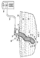
ここで主に図1〜図4、最初に図1を参照すると、トンネル創104または瘻孔を治療するための減圧トンネル創ドレッシング102を有する減圧治療システム100が提示されている。トンネル創傷104は、開口105を有し、図示するように表皮106、真皮108を通り、皮下組織110内に伸びる場合があり、または創床から伸びる場合がある。減圧トンネル創傷ドレッシング102は、トンネル創104内への挿入を可能にするのに十分堅いが、トンネル創104の経路に一致するのに十分可撓性を有している。これは、トンネル創が、頻繁に起こるように10cmより深く伸びる場合に重要である。減圧トンネル創ドレッシング102は、トンネル創104より直径が小さいようにサイズが決められており、それにより、トンネル創縁114と減圧トンネル創ドレッシング102との間に間隙112(図6A)が存在する。減圧トンネル創ドレッシング102に減圧が加えられると、トンネル創縁114は、減圧トンネル創ドレッシング102の外面116と密接に接触する。密接な接触は、減圧トンネル創ドレッシング102が減圧の影響下で膨張するか、または後述するように、減圧によりトンネル創縁114が減圧トンネル創ドレッシング102まで引っ張られることによる。
Referring primarily to FIGS. 1-4 and initially FIG. 1, a reduced
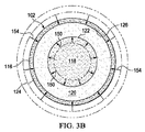
減圧トンネル創ドレッシング102は、独立気泡発泡体から形成されかつ減圧下で膨張するように動作可能な、長手方向コア部材118を含む。減圧トンネル創ドレッシング102はまた、連続気泡発泡体または他のマニホールド材料から形成された第1長手方向同心部材120も含む。第1長手方向同心部材120は、長手方向コア部材118の周囲122すなわち長手方向部分の外面に同心状に配置されている。第1長手方向同心部材120は、減圧下で圧縮されかつ流体を送るように動作可能である。減圧トンネル創ドレッシング102はまた、細孔またはより大きい開口部であり得る複数の穴を有する非粘着性材料から形成された第2長手方向同心部材124も含むことができる。第2長手方向同心部材124は、第1長手方向同心部材120の周囲126に同心状に配置され、第1長手方向同心部材120の遠位端128をさらに覆っている。これらの構成要素についてはさらに後述する。
The reduced pressure tunnel wound dressing 102 includes a
長手方向コア部材118は、減圧トンネル創ドレッシング102の配置に役立つ剛性を提供する独立気泡発泡体から形成されている。長手方向コア部材118は、トンネル創104(さらに深いトンネル創)内への挿入を容易にするのに十分堅いが、トンネル創104に湾曲または折返しがあってもトンネル創104の経路をたどるのに十分な可撓性がある。長手方向コア部材118は、減圧下で膨張する。言い換えれば、長手方向コア部材118は、減圧のない状態では有効横径がDAであるが、長手方向コア部材118の周囲に減圧が加えられると、独立気泡内の捕捉された気体により、長手方向コア部材118が径DB(DB>DA)となるまで膨張する。この膨張は、減圧トンネル創ドレッシング102の外面116とトンネル縁114との間の密接な接触を形成するかまたは形成するのに役立つ。一実施形態では、長手方向コア部材118は、第1閾値減圧より大きい減圧下で膨張することができる。第1閾値減圧を、長手方向コア部材118を形成する独立気泡発泡体の材料特性、たとえば弾性特性、および/または独立気泡発泡体内に保持される気体の組成によって確定することができる。長手方向コア部材118は、減圧トンネル創ドレッシング102の最内部分である。長手方向コア部材を、ポリウレタン、熱可塑性エラストマー、ポリエチレンビニルアセテート(EVA)、ポリイソプレン、ポリスチレンブタジエン、ポリイソブチレン、フルオロポリマー、シリコーンエラストマーまたは他の材料等、弾性発泡材料から形成することができる。
The
第1長手方向同心部材120は、長手方向コア部材118の外側に配置されている。第1長手方向同心部材120は、多孔質の連続気泡発泡体、または減圧および流体を送るように動作可能な他の材料から形成されている。言い換えれば、第1長手方向同心部材120はマニホールドとして機能する。第1長手方向同心部材120を、たとえば、San Antonio,TexasのKCI Inc.から入手可能なGRANUFOAM発泡体、ポリビニルアルコール発泡体、たとえば同様にKCI Inc.から入手可能なWHITEFOAM、ポリウレタン発泡体、ポリビニルアルコール発泡体、連続気泡ポリオレフィン発泡体、熱可塑性エラストマー、ポリエチレンビニルアセテート(EVA)、ポリイソプレン、ポリスチレンブタジエン、ポリイソブチレン、フルオロポリマー、シリコーンエラストマーまたは他の同様の材料から形成することができる。可撓性の維持に役立つように発泡体を可塑化することができる。
The first longitudinal
第2長手方向同心部材124は、減圧トンネル創ドレッシング102の最も外側の部材である。第2長手方向同心部材124は、組織の内部成長を阻止する部材である。第2長手方向同心部材124は、トンネル創104内での減圧トンネル創ドレッシング102の配置を容易にするように滑らかであり得る。第2長手方向同心部材124は、親水性の滑りやすい部材、微多孔性ろ過膜部材、たとえばPTFE部材、GORE材料、穿孔ポリウレタンフィルム、穴のある焼結ポリマー、親水性微多孔性あるいは微細穿孔シリコーンエラストマー、微多孔性あるいは微細穿孔ポリエステル、または親水性特性を与えるようにコーティングまたはプラズマ処理されたアクリル膜であり得る。第2長手方向同心部材124の穴(明示的に示さず)は、10ミクロン〜20ミクロンの細孔であり得るか、またはそれより大きい穴であり得る。
The second longitudinal
第2長手方向同心部材124は、トンネル創104の深さを測定するのに役立つように、長手方向長さに沿ってマーキングを有することができる。トンネル創104から除去する際にいかなる欠損部分も特定するのに役立つように、第2長手方向同心部材124の色または凹凸もまた使用することができる。これに関して、長手方向コア部材118、第1長手方向同心部材120または第2長手方向同心部材124を、トンネル創104内に保持することができる減圧トンネル創ドレッシング102のいかなる部分も位置特定するかまたは識別するのに役立つようにX線不透過性マーカが施されるように形成することができる。
The second longitudinal
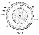
第2長手方向同心部材124および第1長手方向同心部材120は、図3Aに示すように平滑な丸い表面を形成することができ、または図5に示すように複数の小面146のある表面を形成することができる。複数の小面146は、トンネル縁において減圧を分配するのに役立つ。複数の小面146は、特に減圧を加える初期段階中に流体移動を可能にするのに役立ち、かつ流体が遠位端130に通されるのを確実にするのに役立つ。流体は、小面146に近接する領域内に引き込まれる。
The second longitudinal
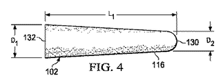
減圧トンネル創ドレッシング102は、遠位端130および近位端132を有している。遠位端130を、トンネル創104の底部134に近接して位置決めすることができる。近位端132は、表皮106(または創床)と同一平面であり得るか、または表皮106(または創床)を越えて延在することができる。近位端132の上に封止部材136が配置されて封止空間138が形成される。近位端132は封止空間138内にある。封止部材136は、流体シールを提供するいかなる材料でもあり得る。流体シールは、関連する特定の減圧源またはサブシステムを考慮して所望の部位において減圧を維持するのに適している。封止部材136は、たとえば不浸透性または半浸透性エラストマー材料であり得る。半浸透性材料の場合、浸透性は、所与の減圧源に対して所望の減圧が維持され得るように十分低くなければならない。トンネル創104が創床から伸びている場合、封止部材136で覆う前に創床および近位端132の上にマニホールド部材を配置することができる。したがって、マニホールド部材および近位端132は封止空間138内にある。
The reduced pressure tunnel wound dressing 102 has a
封止部材136は、患者に面する面に取付装置137を含む。取付装置137は、周辺部、一部または全体的な封止部材136の周囲に延在する医学的に許容可能な感圧接着剤、両面ドレープテープ、ペースト、親水コロイド、ヒドロゲルまたは他の封止装置あるいは要素であり得る。
The sealing
マニホールドという用語は、概して、創床に減圧を加えるか、創床に流体を送達するか、または創床から流体を除去するのに役立つように提供される物質または構造体を指す。マニホールドは、典型的には、マニホールドの周囲の創床に提供されかつ創床から除去される流体を分配する複数の流路または経路を含む。1つの例示的な実施形態では、流路または経路は、創床に提供されかつ創床から除去される流体の分配を促進するように相互接続されている。マニホールドの例としては、限定されないが、たとえば、流路を含むかまたは含むように硬化する、気泡質発泡体、連続気泡発泡体、多孔質組織収集体、液体、ゲルおよび発泡体、特定の生物学的用途に適した発泡体、ガーゼ、フェルトマットまたは他のあらゆる材料、流路として作用する複数の相互接続された気泡または細孔を含むことができる多孔質発泡体、たとえば、San Antonio,TexasのKinetic Concepts,Incorporatedによって製造されるGranuFoam(登録商標)材料等のポリウレタン、連続気泡、網状発泡体等、流路を形成するように配置された構造的要素を有するデバイスが挙げられる。状況によっては、マニホールドを使用して、薬剤、抗菌薬、成長因子およびさまざまな溶液等の流体を組織部位に分配することも可能である。吸収性材料、ウィッキング材料、疎水性材料および親水性材料等、他の層を、マニホールド内にまたはその上に含めることができる。 The term manifold generally refers to a substance or structure that is provided to help apply reduced pressure to the wound bed, deliver fluid to the wound bed, or remove fluid from the wound bed. The manifold typically includes a plurality of channels or pathways that distribute fluid that is provided to and removed from the wound bed around the manifold. In one exemplary embodiment, the channels or pathways are interconnected to facilitate the distribution of fluid that is provided to and removed from the wound bed. Examples of manifolds include, but are not limited to, for example, cellular foams, open cell foams, porous tissue collections, liquids, gels and foams, certain organisms that contain or harden to contain channels. Foams, gauze, felt mats or any other material suitable for biological applications, porous foams that can include a plurality of interconnected bubbles or pores that act as channels, eg, San Antonio, Texas Devices having structural elements arranged to form a flow path, such as polyurethane, open cell, reticulated foam, such as GranuFoam® material manufactured by Kinetic Concepts, Incorporated. In some situations, manifolds can be used to distribute fluids such as drugs, antimicrobial agents, growth factors and various solutions to tissue sites. Other layers, such as absorbent materials, wicking materials, hydrophobic materials and hydrophilic materials can be included in or on the manifold.
減圧インタフェース140を使用して、減圧導管142を封止空間138に流体結合することができる。1つの例示的な実施形態では、減圧インタフェース140は、San Antonio,TexasのKCIから入手可能なT.R.A.C.(登録商標)PadまたはSensa T.R.A.C.(登録商標)Padである。別法として、減圧導管142を、封止部材136を通して封止空間138内に挿入することができる。
A
減圧導管142はまた、減圧源144にも流体結合されている。減圧源144は減圧を提供する。減圧源144は、真空ポンプ、壁面吸込み、マイクロポンプまたは他の供給源等、減圧を供給するいかなる装置でもあり得る。組織部位に加えられる減圧の量および特質は、通常、用途に従って変化するが、減圧は、典型的には、−5mmHg(−667Pa)と−500mmHg(−66.7kPa)との間、より典型的には、−75mmHg(−9.9kPa)と−300mmHg(−39.9kPa)との間、より典型的にはさらに−25mm(−3.33kPa)と−200mmHg(26.6kPa)との間となる。減圧の量を使用して、減圧トンネル創ドレッシング102の外面116とトンネル縁114との間の力を制御することができる。
The
減圧とは、治療を受けている組織部位において周囲圧力より低い圧力を指す。大部分の場合、減圧は、患者が位置する大気圧より低くなる。別法として、減圧は、組織部位における静水圧より低い場合もある。特に示さない限り、本明細書で述べる圧力の定量値はゲージ圧である。送達される減圧は、一定であるかまたは変化する(パターン化されるかまたはランダム)場合があり、連続的にあるいは断続的に送達される場合がある。 Depressurization refers to a pressure below ambient pressure at the tissue site undergoing treatment. In most cases, the reduced pressure will be lower than the atmospheric pressure where the patient is located. Alternatively, the reduced pressure may be lower than the hydrostatic pressure at the tissue site. Unless otherwise indicated, the quantitative values of pressure described herein are gauge pressures. The reduced pressure delivered can be constant or variable (patterned or random) and can be delivered continuously or intermittently.
主に図3Aを参照すると、横断面図で示す構成要素の相対的な面積および寸法を変更することができる。減圧トンネル創ドレッシング102の全直径は、トンネル創104の共通サイズに従って変更することができ、たとえば0.25センチメートルから8センチメートルの長さである。全体的な所望のサイズに応じて、第2長手方向同心部材124は、厚さが0ミクロンから20ミクロンの範囲となる可能性があり、典型的には10ミクロンから15ミクロンの範囲である。第1長手方向同心部材120は、厚さが2mmから4cmの範囲となる可能性がある。長手方向コア部材118は、直径が1cmから5cmの範囲であり得る。これらの寸法は、例として示されており、限定するように意図されていない。減圧トンネル創ドレッシング102を、異なるサイズのトンネル創に適応するように要求に応じて変更することができる。横断面における相対的な面積に関して、長手方向コア部材118は、典型的には、20%から90%の範囲となる。第1長手方向同心部材120は、典型的には、10%から60%の範囲となる。第2長手方向同心部材124を、0%から10%、より典型的には0%と2%との間で変更することができる。
Referring primarily to FIG. 3A, the relative areas and dimensions of the components shown in the cross-sectional view can be varied. The overall diameter of the reduced pressure tunnel wound dressing 102 can vary according to the common size of the tunnel wound 104, for example, 0.25 centimeters to 8 centimeters long. Depending on the overall desired size, the second longitudinal
図4に示すように、減圧トンネル創ドレッシング102を、その長手方向輪郭において近位端132と遠位端130またはそのいずれかの部分との間で先細りにすることができる。大きい方の径は、通常近位端132である。たとえば、近位端132は、有効断面径D1を有することができ、遠位端130(または実際には遠位端130に近いが長手方向長さL1のわずかな距離、たとえば5%内側である)は、有効断面径がD2(D1はD2より大きい)であり得る。底部から外側に治癒が発生するため、先細りは、この治癒のパターンに役立つことができる。いくつかの実施形態では、減圧トンネル創ドレッシング102を先細りにされなくてもよく、その長手方向側面図において一定輪郭を有することができる。
As shown in FIG. 4, the reduced pressure tunnel wound dressing 102 can taper between the
いくつかの実施形態では、第2長手方向同心部材124を省略することができる。こうした場合、第1長手方向同心部材120を、組織内部成長を阻止するように、細孔サイズが1インチ辺り少なくとも160細孔(ppi)である連続気泡発泡体から形成することができる。さらに、第2長手方向同心部材124なしにより密度の高い発泡体を使用することにより、内部成長の問題なしに遠位端130を切断することが容易になる。
In some embodiments, the second longitudinal
図1〜図4および図6A〜図6Bを参照すると、動作時、1つの例示的な実施形態によれば、初期ステップとして減圧トンネル創ドレッシング102のサイズが決められる。減圧トンネル創ドレッシング102のサイズ決めは、最も広い部分がトンネル創104の直径より小さい有効径であるドレッシングを選択することを含むことができる。言い換えれば、減圧トンネル創ドレッシング102は、外面116とトンネル縁114との間に間隙112(図6A)が存在するように選択される。サイズ決めはまた、遠位端130が底部134にまたはその近くにあり、近位端132が表皮106あるいは創床と同一平面にあるかまたはわずかにのみ、たとえば減圧トンネル創ドレッシング102の長さの5%−10%を越えて延在するように、適切な長さの減圧トンネル創ドレッシング102を選択することを含むことができる。長さを、近位端132または場合によっては遠位端130を切断することによっても調整することができる。遠位端130が切断される場合、遠位端130を、穿孔封止材料で覆う必要がある場合がある。
1-4 and 6A-6B, in operation, according to one exemplary embodiment, the reduced pressure tunnel wound dressing 102 is sized as an initial step. Sizing the reduced-pressure tunnel wound dressing 102 may include selecting a dressing whose widest portion is an effective diameter that is smaller than the diameter of the tunnel wound 104. In other words, the reduced pressure tunnel wound dressing 102 is selected such that there is a gap 112 (FIG. 6A) between the
サイズが決められた減圧トンネル創ドレッシング102は、遠位端130がトンネル創104の底部134に近接するまでトンネル創104内に挿入される。瘻孔が治療されている場合、減圧トンネル創ドレッシング102は、瘻孔を充填するように推定される距離だけ挿入される。トンネル創104の開口105が創床にある場合、マニホールド部材を、創床および減圧トンネル創ドレッシング102の近位端132の上に配置することができる。
The sized reduced pressure tunnel wound dressing 102 is inserted into the tunnel wound 104 until the
減圧トンネル創ドレッシング102および適用可能な場合はマニホールド部材が封止部材136によって覆われることにより封止空間138が生成される。封止部材136は、取付装置137によって無傷の表皮106に対して保持される。
A reduced pressure tunnel wound dressing 102 and, where applicable, a manifold member is covered by a sealing
減圧導管142が封止空間138に流体結合される。これを、封止部材136の下に減圧インタフェース140を付与し、そこに減圧導管142を結合することによって達成することができる。別法として、封止部材136に穴を形成することができ、その穴に減圧導管142の端部を挿入して封止することができる。流体結合されると、減圧は、減圧導管142を通して封止空間138に送達される。
A
図3A〜図3Bおよび図6A〜図6Bを参照して、減圧の効果を説明する。減圧が加えられる前(図3Aおよび図6A)、減圧トンネル創ドレッシング102は、直径Daを有し、トンネル縁114と減圧トンネル創ドレッシング102の外面116との間に間隙112があって、トンネル創104に嵌まる。減圧が加えられると(図3Bおよび図6B)、長手方向コア部材118は矢印150によって示唆されるように膨張し、その膨張は、周囲圧が絶対圧力スケールで低下する際に独立気泡内の気体が膨張することによる。減圧はまた、矢印152(図6B)によって示唆されるように、トンネル縁114を減圧トンネル創ドレッシング102に向かって付勢する。さらに、第1長手方向同心部材120は、矢印154によって示唆されるように圧縮される(図3B)。これらの動きのうちの1つまたは複数により、減圧トンネル創ドレッシング102とトンネル縁114との間に密接な接触がもたらされる。減圧は、治療が望まれる限り加えられる。減圧治療時間の後、減圧が解除される。トンネル創104に対する外傷を回避するために、減圧を段階的に解除することが望ましい場合がある。
The effect of decompression will be described with reference to FIGS. 3A to 3B and FIGS. 6A to 6B. Before vacuum is applied (FIGS. 3A and FIG. 6A), vacuum tunnel wound dressing 102 has a diameter D a, there is a
減圧を解除した結果、長手方向コア部材118は、その元のサイズまたはおよそその元のサイズまで収縮し、第1長手方向同心部材120は、その元のサイズまたはおよそその元のサイズまで膨張する。さらに、トンネル縁と減圧トンネル創ドレッシング102との間の間隙112または間隙112の一部が回復する。これらの変化のうちの1つまたは複数により、トンネル創104からの減圧トンネル創ドレッシング102の引出しが容易になる。いくつかの実施形態では、トンネル創104から減圧トンネル創ドレッシング102の除去を容易にするために、減圧トンネル創ドレッシング102内に陽圧下で生理食塩水または別の液体を送ることができる。また、図8の実施形態に関連して考察するように、治療中に流体を導入することができる。
As a result of releasing the vacuum, the
減圧トンネル創ドレッシング102を、多くの技法を使用して製造することができる。1つの例示的な実施形態によれば、構成要素またはそれらの合計は同時押出成形される。長手方向コア部材118を、独立気泡発泡体から押出成形することができ、その後、長手方向コア部材118の周囲に連続気泡発泡体を押出成形して第1長手方向同心部材120を形成することができる。第2長手方向同心部材124を、第1長手方向同心部材120の周囲126にあてがうことができる。第2長手方向同心部材124が十分に多孔質でない場合、ピンを使用して、第2長手方向同心部材124を穿孔することができ、またはレーザを使用して穴を生成することができる。レーザが使用される場合、長手方向コア部材118を穿孔するのを避けるように、レーザの電力印加を制限することができ、またはレーザを接線で与えることができる。別法として、長手方向コア部材118を押出成形し、その後、第1長手方向同心部材120を形成する材料でコーティングすることができる。別法として、気体で充填されたスチレンビードを加熱して長手方向コア部材118を形成することができ、その後、長手方向コア部材118の上に連続気泡発泡体を押出成形して第1長手方向同心部材120を形成することができる。
The reduced pressure tunnel wound dressing 102 can be manufactured using a number of techniques. According to one exemplary embodiment, the components or their sum are coextruded. The
第2長手方向同心部材124を、ラップ剤によって形成するかまたはある巻き角(wind angle)で形成することができる。ホットメルトを使用していくつかの部分を溶融することができる。第2長手方向同心部材124を、第1長手方向同心部材120の外側に押出成形することも可能である。
The second longitudinal
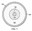
ここで主に図7を参照すると、減圧トンネル創ドレッシング102が、半剛性内部コア部材155があるように横断面図で示されている。この半剛性内部コア部材155の追加により、減圧トンネル創ドレッシング102に剛性が追加される。追加の剛性は、減圧トンネル創ドレッシング102を入り組んだトンネル創104内に配置するのにさらに役立つことができる。半剛性内部コア部材155を、たとえば適合性のあるシリコーン、ポリウレタン、熱可塑性エラストマー、架橋エラストマーまたは他の同様の材料から形成することができる。
Referring now primarily to FIG. 7, the reduced pressure tunnel wound dressing 102 is shown in cross-section with a semi-rigid
ここで図8を参照すると、減圧トンネル創ドレッシング102が、複数の液体導管158が追加されて示されている。液体導管158を使用して、トンネル創104にフラッシング液等の薬剤を提供することができる。明示的には示さないが、液体導管158は、その長手方向長さに沿って、トンネル創104を通して液体を分配するように複数の穴を有することができる。
Referring now to FIG. 8, a reduced pressure tunnel wound dressing 102 is shown with a plurality of
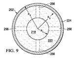
ここで主に図9を参照すると、減圧トンネル創ドレッシング202の別の実施形態が提示されている。減圧トンネル創ドレッシング202は、連続気泡発泡体から形成されかつ横方向外半径Riを有する、長手方向コア部材218を有している。第1長手方向同心部材220が、長手方向コア部材218を包囲し、横方向外半径Riiを有している。第2長手方向個同心部材224が、第1長手方向同心部材220を包囲することができる。第2長手方向同心部材224は、横方向外半径Riiiを有している。この実施形態における長手方向コア部材218は、図1の長手方向同心部材120と同様の材料から作製され、同様の寸法および機能を有している。第1長手方向同心部材220は、図1の長手方向コア部材118と同様の材料から作製され、同様の寸法および機能を有している。複数の導管256が、第2長手方向同心部材を長手方向コア部材218に流体結合して、この実施形態ではマニホールドとして機能する。減圧トンネル創ドレッシング202では、図5に示すもののような小面のある第2長手方向同心部材224を使用することが有利であり得る。小面は、減圧をトンネル縁に分配するのに役立つ。
Referring now primarily to FIG. 9, another embodiment of a reduced pressure tunnel wound dressing 202 is presented. The reduced pressure tunnel wound dressing 202 has a
長手方向コア部材218は、減圧を、減圧トンネル創ドレッシング202の中心を下って導管256にまたは端部開口部(図示せず)に送る。減圧は、長手方向コア部材218を移動する際にこのように最小限に制限される。したがって、遠位端においてより顕著な圧力差を達成することができる。このように減圧を減圧トンネル創ドレッシング202で送ることにより、減圧トンネル創ドレッシング202をトンネル創の最も遠いリーチまたは部分から引き戻すことによって、底部134からトンネル創104(図1)の縫合(閉鎖)を促進することができる。これが、トンネル創104の底部104を収縮させ、三次縫合の形態でトンネル壁の一方の側が他方の側に付着するのを促進するのに役立つ。減圧トンネル創ドレッシング202の存在により、創傷が底部から閉鎖されるまで一次縫合を遷延させることができる。
図10Aおよび図10Bを参照すると、代替的な現圧トンネル創ドレッシング302が提示されている。この実施形態では、減圧トンネル創ドレッシング302は、不浸透性弾性材料から形成された円柱状シェルブラダ304を含む。円柱状シェルブラダ304は、モデリングバルーンに形態が類似している。円柱状シェルブラダ304の外側305は、第1同心部材306によって包囲されており、第1同心部材306は、連続気泡発泡体、または第1長手方向同心部材120に関連して上述した他の材料等、マニホールド材料から形成されている。第1同心部材306を、第2同心部材(図示しないが第2同心部材124に類似する)によって包囲することができる。
Referring to FIGS. 10A and 10B, an alternative current pressure tunnel wound dressing 302 is presented. In this embodiment, the reduced pressure tunnel wound dressing 302 includes a
円柱状シェルブラダ304が、その近位端308および遠位端310の両方において封止されて内部空間312を形成している。内部空間312は、空気、窒素または他の不活性ガス等の気体で充填されている。円柱状シェルブラダ304の遠位端310は、円柱状シェルブラダ304内に折り返されて、減圧に晒された時に広がるように動作可能な部分314を形成している。図10Aは、たたまれた状態をもたらすように折り込まれた円柱状シェルブラダ304を示す。減圧が加えられると、円柱状シェルブラダ304内の気体の相対圧力が上昇して、部分314が、長手方向外側方向において展開または拡張する。したがって、図10Bに示すように、減圧が加えられ、矢印316によって示唆されるように、減圧トンネル創ドレッシング302が初期長手方向長さL1(図10A)から長さL2(図10B)まで膨張する。減圧トンネル創ドレッシング302は、遠位端310が完全に広がるまで膨張し続けることができる。
A
減圧トンネル創ドレッシング302がトンネル創(たとえば図1のトンネル創104)内に挿入される。トンネル創が、封止部材(たとえば図1の封止部材136)で覆われて、トンネル創および減圧トンネル創ドレッシング302の上に封止空間(たとえば図1の封止空間138)が形成される。そして、減圧導管(たとえば図1の減圧導管142)によって封止空間に減圧が加えられる。減圧が加えられると、減圧トンネル創ドレッシング302は、減圧トンネル創ドレッシング302がトンネル創の底部(たとえば図1の底部134)等の障害物に達するまで広がる。さらに、減圧トンネル創ドレッシング302の外側318が膨張して、トンネル創のトンネル縁との密接な接触を形成するかまたは形成するのに役立つ。言い換えれば、減圧トンネル創ドレッシング302は、初期径D1から膨張径D2(D2>D1)になる。減圧はまた、トンネル縁を外面318に向かって引っ張る。減圧を、所望の治療時間、第1同心部材306を用いてトンネル創のトンネル縁に加えることができる。
A reduced pressure tunnel wound dressing 302 is inserted into the tunnel wound (eg, tunnel wound 104 of FIG. 1). The tunnel wound is covered with a sealing member (eg, sealing
治療後、減圧が解除され、トンネル縁が減圧トンネル創ドレッシング302から後退し、それにより、減圧トンネル創ドレッシング302のトンネル創からの後退が容易になる。中心ブラダ310は、圧力が解除されると、中心ブラダ310が元の位置まで後退するように記憶効果があるように成形されている。減圧トンネル創ドレッシング302の外側の周囲圧力が、減圧トンネル創ドレッシング302を元の位置に戻るように付勢する。
After treatment, the reduced pressure is released and the tunnel edge retracts from the reduced pressure tunnel wound dressing 302, thereby facilitating the reduced pressure tunnel wound dressing 302 to retract from the tunnel wound. The
さらに別の代替実施形態では、減圧トンネル創ドレッシング302を、内部空間312に陽圧を提供する流体源に結合することができる。医療提供者は、減圧トンネル創ドレッシング302を挿入し、その後、要求に応じて流体源を使用して減圧トンネル創ドレッシング302を手動で膨張させることができる。流体源は、たとえば加圧された生理食塩水源であり得る。
In yet another alternative embodiment, the reduced pressure tunnel wound dressing 302 can be coupled to a fluid source that provides positive pressure to the
再び図1〜図4を参照すると、一実施形態では、減圧トンネル創ドレッシング102を、ともに生体吸収性(bioresorbable)材料または溶解性材料から作製される、長手方向コア部材118および第1長手方向同心部材120(ただし第2長手方向同心部材124はない)で形成することができる。この実施形態では、減圧トンネル創ドレッシング102を、減圧トンネル創ドレッシング102が溶解するまでトンネル創104内に残すことができる。同様の実施形態では、減圧トンネル創ドレッシング102は、同様に形成されるが、図7の半剛性内部コア部材155が追加されている。半剛性内部コア部材155は、取外し可能であり得る。こうした倍、半剛性内部コア部材155は、減圧トンネル創ドレッシング102を配置するために使用され、その後取り外される。減圧は所望の治療時間、加えられる。そして、減圧トンネル創ドレッシング102は、溶解するまで適所に残ることができる。
1-4, in one embodiment, the reduced pressure tunnel wound dressing 102 and the
1つの例示的な実施形態では、長手方向コア部材118は、治療範囲で減圧下(たとえば−75mmHg − −200mmHg)で、減圧トンネル創ドレッシング102の全直径が、減圧源が加えられる前の直径より大きいように、十分に膨張する。言い換えれば、直径を、減圧トンネル創ドレッシングのD2がD1の100%を超える、たとえばD2=101%D1、D2=102%D1、D2=103%D1、D2=104%D1、D2=105%D1、D2=106%D1、D2=110%D1、D2=115%D1等(またはそれらの間のあらゆる範囲)であるようにすることができる。
In one exemplary embodiment, the
本明細書の実施形態は、トンネル創が減圧下でつぶれないようにするのに役立つ。減圧トンネル創ドレッシングは、減圧下で膨張している部分によってこうしたつぶれに能動的に抵抗する。本明細書における減圧トンネル創ドレッシングは、その長さに沿ったトンネル縁とドレッシングとの間の均一な密接した接触を促進する。本明細書における減圧トンネル創ドレッシングは、トンネル創の種々の深さに対して容易にサイズが決められる。減圧トンネル創ドレッシングは、曲がりくねって入り組んだ経路のある多くのトンネル創における配置を可能にするように剛性および可撓性を提供し、ドレッシングの膨張は、トンネル創のそれらの長さに沿った開口の変動に適応する。減圧の解除により、トンネル縁から減圧トンネル創ドレッシングが能動的に後退する。 Embodiments herein help to prevent tunnel wounds from collapsing under reduced pressure. The reduced pressure tunnel wound dressing actively resists such collapse by the part expanding under reduced pressure. The reduced pressure tunnel wound dressing herein promotes uniform intimate contact between the tunnel edge and the dressing along its length. The reduced pressure tunnel wound dressing herein is easily sized for various depths of the tunnel wound. Depressurized tunnel wound dressings provide rigidity and flexibility to allow placement in many tunnel wounds with tortuous and intricate paths, with the expansion of the dressing opening along their length of the tunnel wound Adapt to fluctuations. Release of the decompression actively retracts the decompression tunnel wound dressing from the tunnel edge.
本明細書の主題およびその利点を、いくつかの例示的な限定しない実施形態の文脈で開示したが、添付の特許請求の範囲によって定義される本発明の範囲から逸脱することなく、さまざまな変更、置換、並べ替えおよび改変を行うことができることが理解されるべきである。いずれか1つの実施形態に関連して記載されているあらゆる特徴を他のいずれの実施形態にも適用可能であり得ることが理解されよう。たとえば、図7の半剛性内部コア部材155および図8の導管を、本明細書の他のいずれの実施形態にも追加することができる。
While the subject matter of this specification and its advantages have been disclosed in the context of some exemplary non-limiting embodiments, various modifications can be made without departing from the scope of the invention as defined by the appended claims. It should be understood that substitutions, permutations and modifications can be made. It will be understood that any feature described in connection with any one embodiment may be applicable to any other embodiment. For example, the semi-rigid
上述した利益および利点は、1つの実施形態に関連する場合があり、またはいくつかの実施形態に関連する場合があることが理解されよう。「1つの」項目を参照する場合、それはそれらの項目のうちの1つまたは複数を参照することがさらに理解されよう。 It will be appreciated that the benefits and advantages described above may relate to one embodiment or may relate to several embodiments. It will be further understood that when referring to “a” item, it refers to one or more of those items.
本明細書に記載した方法のステップを、あらゆる好適な順序で、または適切な場合は同時に行うことができる。 The steps of the methods described herein can be performed in any suitable order or, where appropriate, simultaneously.
適切な場合は、上述した実施形態のうちのいずれかの態様を、記載した他の実施形態のいずれかの態様に結合して、相当するかまたは異なる特性を有しかつ同じかまたは異なる問題に対処するさらなる例を形成することができる。 Where appropriate, any aspect of the above-described embodiments may be combined with any aspect of the other described embodiments to have the same or different characteristics and the same or different problems. Additional examples can be formed to address.
実施形態の上記説明は、単に例として与えられ、当業者によってさまざまな変更を行うことができることが理解されよう。上記明細書、例およびデータは、構造の完全な説明および本明細書の主題の例示的な実施形態の使用を提供する。さまざまな実施形態を、ある程度の特殊性をもって、または1つあるいは複数の個々の実施形態に関連して上述したが、当業者は、特許請求の範囲の範囲から逸脱することなく開示した実施形態に多数の変更を行うことができる。 It will be appreciated that the above description of embodiments is given by way of example only and various modifications can be made by those skilled in the art. The above specification, examples and data provide a complete description of the structure and use of exemplary embodiments of the subject matter herein. While various embodiments have been described above with a certain degree of particularity or in connection with one or more individual embodiments, those skilled in the art will recognize the disclosed embodiments without departing from the scope of the claims. Many changes can be made.
Claims (38)
独立気泡発泡体から形成されかつ第1閾値より大きい減圧下で膨張するように動作可能な長手方向コア部材と、
マニホールド材料から形成された第1長手方向同心部材であって、前記長手方向コア部材の周囲に同心状に配置され、前記第1閾値より大きい減圧下で圧縮されるように動作可能な第1長手方向同心部材と、
を具備することを特徴とする減圧トンネル創ドレッシング。 In decompression tunnel wound dressing to treat tunnel wounds or fistulas,
A longitudinal core member formed of closed cell foam and operable to expand under reduced pressure greater than a first threshold;
A first longitudinal concentric member formed from a manifold material, the first longitudinal concentric member disposed concentrically around the longitudinal core member and operable to be compressed under a reduced pressure greater than the first threshold. Directional concentric members;
A reduced pressure tunnel wound dressing characterized by comprising:
減圧トンネル創ドレッシングであって、
独立気泡発泡体から形成されかつ第1閾値より大きい減圧下で膨張するように動作可能な長手方向コア部材と、
マニホールド材料から形成された第1長手方向同心部材であって、前記長手方向コア部材の周囲に同心状に配置され、前記第1閾値より大きい減圧下で圧縮されるように動作可能な第1長手方向同心部材と、
を備える減圧トンネル創ドレッシングと、
前記減圧トンネル創ドレッシングの上に封止空間を形成するように患者の皮膚の一部を覆うドレープと、
前記減圧トンネル創ドレッシングに流体結合された減圧源と、
を具備することを特徴とするシステム。 In a decompression system to treat a patient's tunnel wound or fistula,
Decompression tunnel wound dressing,
A longitudinal core member formed of closed cell foam and operable to expand under reduced pressure greater than a first threshold;
A first longitudinal concentric member formed from a manifold material, the first longitudinal concentric member disposed concentrically around the longitudinal core member and operable to be compressed under a reduced pressure greater than the first threshold. Directional concentric members;
A decompression tunnel wound dressing comprising:
A drape covering a portion of the patient's skin to form a sealed space above the reduced pressure tunnel wound dressing;
A reduced pressure source fluidly coupled to the reduced pressure tunnel wound dressing;
The system characterized by comprising.
第1閾値より大きい減圧下で膨張するように動作可能な独立気泡発泡体から長手方向コア部材を押出成形するステップと、
前記第1閾値より大きい減圧下で圧縮するように動作可能な連続気泡発泡体から第1長手方向同心部材を、前記第1長手方向同心部材が前記長手方向コア部材の周囲に形成されるように押出成形するステップと、
前記第1長手方向同心部材の周囲に第2長手方向同心部材をあてがうステップであって、前記第2長手方向同心部材が複数の穴を有する不浸透性材料を含む、ステップと、
を含むことを特徴とする方法。 In a method of manufacturing a reduced pressure tunnel wound dressing,
Extruding a longitudinal core member from a closed cell foam operable to expand under reduced pressure greater than a first threshold;
A first longitudinal concentric member is formed from an open cell foam operable to compress under reduced pressure greater than the first threshold, such that the first longitudinal concentric member is formed around the longitudinal core member. Extruding, and
Applying a second longitudinal concentric member around the first longitudinal concentric member, the second longitudinal concentric member comprising an impermeable material having a plurality of holes;
A method comprising the steps of:
マニホールド材料から形成され、かつ第1閾値より大きい減圧下で圧縮されるように動作可能な長手方向コア部材と、
独立気泡発泡体から形成された第1長手方向同心部材であって、前記長手方向コア部材の周囲に同心状に配置され、前記第1閾値より大きい減圧下で膨張するように動作可能な第1長手方向同心部材と、
前記長手方向コア部材および第2長手方向同心部材を流体結合する複数の流体導管と、
を具備することを特徴とする減圧トンネル創ドレッシング。 In decompression tunnel wound dressing to treat tunnel wounds or fistulas,
A longitudinal core member formed from a manifold material and operable to be compressed under a reduced pressure greater than a first threshold;
A first longitudinal concentric member formed from closed cell foam, the first longitudinally concentric member being concentrically disposed around the longitudinal core member and operable to expand under reduced pressure greater than the first threshold. A longitudinal concentric member;
A plurality of fluid conduits fluidly coupling the longitudinal core member and the second longitudinal concentric member;
A reduced pressure tunnel wound dressing characterized by comprising:
気体が充填される円柱状シェルブラダであって、外面、近位端および遠位端を有する円柱状シェルブラダと、
前記円柱状シェルブラダの前記外面を覆う連続気泡発泡体層と、
を具備し、
前記円柱状シェルブラダの前記遠位端が、前記円柱状シェルブラダ内に折り返されて、減圧に晒されると広がるように動作可能な部分を形成することを特徴とする減圧トンネル創ドレッシング。 In decompression tunnel wound dressing to treat tunnel wounds or fistulas,
A cylindrical shell bladder filled with gas, the cylindrical shell bladder having an outer surface, a proximal end and a distal end;
An open-cell foam layer covering the outer surface of the cylindrical shell bladder;
Comprising
A reduced pressure tunnel wound dressing wherein the distal end of the cylindrical shell bladder is folded back into the cylindrical shell bladder to form a portion operable to expand when exposed to reduced pressure.
減圧下で膨張するように適合された、独立気泡発泡体から形成された長手方向コア部材と、
マニホールド材料から形成された第1長手方向同心部材であって、前記長手方向コア部材の周囲に同心状に配置されている第1長手方向同心部材と、
を具備することを特徴とする減圧トンネル創ドレッシング。 In decompression tunnel wound dressing to treat tunnel wounds or fistulas,
A longitudinal core member formed of closed cell foam adapted to expand under reduced pressure;
A first longitudinal concentric member formed from a manifold material, the first longitudinal concentric member disposed concentrically around the longitudinal core member;
A reduced pressure tunnel wound dressing characterized by comprising:
マニホールド材料から形成されかつ第1閾値より大きい減圧下で圧縮されるように動作可能な長手方向コア部材と、
独立気泡発泡体から形成された第1長手方向同心部材であって、前記長手方向コア部材の周囲に同心状に配置され、前記第1閾値より大きい減圧下で膨張するように動作可能な第1長手方向同心部材と、
前記長手方向コア部材に流体結合された、前記第1長手方向同心部材の複数の流体導管と、
を具備することを特徴とする減圧トンネル創ドレッシング。 In decompression tunnel wound dressing to treat tunnel wounds or fistulas,
A longitudinal core member formed from a manifold material and operable to be compressed under a reduced pressure greater than a first threshold;
A first longitudinal concentric member formed from closed cell foam, the first longitudinally concentric member being concentrically disposed around the longitudinal core member and operable to expand under reduced pressure greater than the first threshold. A longitudinal concentric member;
A plurality of fluid conduits of the first longitudinal concentric member fluidly coupled to the longitudinal core member;
A reduced pressure tunnel wound dressing characterized by comprising:
気体が充填される円柱状シェルブラダであって、外面、近位端および遠位端を有する円柱状シェルブラダと、
前記円柱状シェルブラダの前記外面を覆う連続気泡発泡体層と、
を具備し、
前記円柱状シェルブラダの前記遠位端が、前記円柱状シェルブラダ内に折り返されて、減圧に晒されると広がるように動作可能な部分を形成する
ことを特徴とする減圧トンネル創ドレッシング。 In decompression tunnel wound dressing to treat tunnel wounds or fistulas,
A cylindrical shell bladder filled with gas, the cylindrical shell bladder having an outer surface, a proximal end and a distal end;
An open-cell foam layer covering the outer surface of the cylindrical shell bladder;
Comprising
A reduced pressure tunnel wound dressing wherein the distal end of the cylindrical shell bladder is folded back into the cylindrical shell bladder to form a portion operable to expand when exposed to reduced pressure.
請求項24乃至37の何れか一項に記載の減圧トンネル創ドレッシングと、
患者の皮膚の一部を覆って、前記減圧トンネル創ドレッシングの上に封止空間を形成するドレープと、
前記減圧トンネル創ドレッシングに流体結合された減圧源と、
を具備することを特徴とする減圧システム。 In a decompression system to treat a patient's tunnel wound or fistula,
A reduced pressure tunnel wound dressing according to any one of claims 24 to 37;
A drape that covers a portion of the patient's skin and forms a sealed space over the reduced pressure tunnel wound dressing;
A reduced pressure source fluidly coupled to the reduced pressure tunnel wound dressing;
A decompression system comprising:
Applications Claiming Priority (3)
| Application Number | Priority Date | Filing Date | Title |
|---|---|---|---|
| US201161558642P | 2011-11-11 | 2011-11-11 | |
| US61/558,642 | 2011-11-11 | ||
| PCT/US2012/064689 WO2013071243A2 (en) | 2011-11-11 | 2012-11-12 | Reduced-pressure, tunnel-wound dressings, systems, and methods |
Publications (3)
| Publication Number | Publication Date |
|---|---|
| JP2014534891A JP2014534891A (en) | 2014-12-25 |
| JP2014534891A5 JP2014534891A5 (en) | 2016-01-07 |
| JP6184969B2 true JP6184969B2 (en) | 2017-08-23 |
Family
ID=47326333
Family Applications (1)
| Application Number | Title | Priority Date | Filing Date |
|---|---|---|---|
| JP2014541374A Expired - Fee Related JP6184969B2 (en) | 2011-11-11 | 2012-11-12 | Depressurized tunnel wound dressing, system and method |
Country Status (7)
| Country | Link |
|---|---|
| US (3) | US10137037B2 (en) |
| EP (1) | EP2776084B1 (en) |
| JP (1) | JP6184969B2 (en) |
| CN (1) | CN103889477B (en) |
| AU (1) | AU2012334990B2 (en) |
| CA (1) | CA2850956C (en) |
| WO (1) | WO2013071243A2 (en) |
Families Citing this family (52)
| Publication number | Priority date | Publication date | Assignee | Title |
|---|---|---|---|---|
| US20130096518A1 (en) | 2007-12-06 | 2013-04-18 | Smith & Nephew Plc | Wound filling apparatuses and methods |
| US11253399B2 (en) | 2007-12-06 | 2022-02-22 | Smith & Nephew Plc | Wound filling apparatuses and methods |
| CN106974683B (en) | 2011-02-04 | 2020-02-21 | 马萨诸塞州大学 | Negative pressure wound closure device |
| US9421132B2 (en) | 2011-02-04 | 2016-08-23 | University Of Massachusetts | Negative pressure wound closure device |
| WO2013066426A2 (en) | 2011-06-24 | 2013-05-10 | Kci Licensing, Inc. | Reduced-pressure dressings employing tissue-fixation elements |
| USD733896S1 (en) | 2012-05-04 | 2015-07-07 | Genadyne Biotechnologies, Inc. | Abdominal dressing |
| WO2013175310A2 (en) | 2012-05-22 | 2013-11-28 | Smith & Nephew Plc | Apparatuses and methods for wound therapy |
| CA2874396A1 (en) | 2012-05-22 | 2014-01-23 | Smith & Nephew Plc | Wound closure device |
| CA2874581C (en) | 2012-05-24 | 2022-06-07 | Smith & Nephew Inc. | Devices and methods for treating and closing wounds with negative pressure |
| AU2013290346B2 (en) | 2012-07-16 | 2018-06-07 | Smith & Nephew, Inc. | Negative pressure wound closure device |
| DE102013002497A1 (en) | 2013-02-13 | 2014-08-14 | Paul Hartmann Ag | Bandage kit for the treatment of wound cavities |
| EP2968016B1 (en) | 2013-03-13 | 2018-07-11 | Smith&Nephew, Inc. | Negative pressure wound closure device and systems and methods of use in treating wounds with negative pressure |
| US10159771B2 (en) | 2013-03-14 | 2018-12-25 | Smith & Nephew Plc | Compressible wound fillers and systems and methods of use in treating wounds with negative pressure |
| CA2901882C (en) * | 2013-03-14 | 2021-04-13 | Kci Licensing, Inc. | Micro-porous conduit |
| AU2014291873B2 (en) | 2013-07-16 | 2019-01-24 | Smith & Nephew Plc | Apparatus for wound therapy |
| JP6723917B2 (en) | 2013-10-21 | 2020-07-15 | スミス アンド ネフュー インコーポレイテッド | Negative pressure wound closure device |
| JP6742908B2 (en) | 2014-01-21 | 2020-08-19 | スミス アンド ネフュー ピーエルシーSmith & Nephew Public Limited Company | Crushable negative pressure wound dressing |
| US10179073B2 (en) | 2014-01-21 | 2019-01-15 | Smith & Nephew Plc | Wound treatment apparatuses |
| US10226566B2 (en) | 2014-04-23 | 2019-03-12 | Genadyne Biotechnologies, Inc. | System and process for removing bodily fluids from a body opening |
| JP6749248B2 (en) * | 2014-05-09 | 2020-09-02 | ケーシーアイ ライセンシング インコーポレイテッド | Dressing with shrink layer for linear tissue sites |
| EP3354241B1 (en) | 2014-05-09 | 2020-12-30 | 3M Innovative Properties Company | Disruptive dressing for use with negative pressure and fluid instillation |
| US10898217B2 (en) | 2014-05-09 | 2021-01-26 | Kci Licensing, Inc. | Dressing providing apertures with multiple orifice sizes for negative-pressure therapy |
| AU2015292343B2 (en) * | 2014-07-24 | 2020-05-07 | Solventum Intellectual Properties Company | Combination fluid instillation and negative pressure dressing |
| DE102014216139A1 (en) * | 2014-08-13 | 2016-02-18 | Paul Hartmann Ag | Wound dressing kit for the treatment of wound cavities |
| EP3288509B1 (en) | 2015-04-29 | 2022-06-29 | Smith & Nephew, Inc | Negative pressure wound closure device |
| TWI597075B (en) * | 2015-05-12 | 2017-09-01 | Hydrophilic polyurethane, hydrophilic polyurethane foam and its preparation Wet wound dressing | |
| CN106310497A (en) * | 2015-07-01 | 2017-01-11 | 泰升国际科技股份有限公司 | Negative pressure therapeutic apparatus |
| US10575991B2 (en) | 2015-12-15 | 2020-03-03 | University Of Massachusetts | Negative pressure wound closure devices and methods |
| US11471586B2 (en) | 2015-12-15 | 2022-10-18 | University Of Massachusetts | Negative pressure wound closure devices and methods |
| US10814049B2 (en) | 2015-12-15 | 2020-10-27 | University Of Massachusetts | Negative pressure wound closure devices and methods |
| AU2017256692B2 (en) | 2016-04-26 | 2022-03-03 | Smith & Nephew Plc | Wound dressings and methods of use with integrated negative pressure source having a fluid ingress inhibition component |
| US11135351B2 (en) | 2016-08-30 | 2021-10-05 | Smith & Nephew Plc | Systems and methods for applying reduced pressure therapy |
| EP3290062A1 (en) * | 2016-08-31 | 2018-03-07 | B. Braun Surgical, S.A. | Medical device, in particular for treating fistulas |
| EP3518847B1 (en) | 2016-09-27 | 2023-03-01 | Smith & Nephew plc | Wound closure devices with dissolvable portions |
| WO2018085457A1 (en) | 2016-11-02 | 2018-05-11 | Smith & Nephew Inc. | Wound closure devices |
| US11819387B2 (en) * | 2017-06-07 | 2023-11-21 | Kci Licensing, Inc. | Composite dressings for improved granulation and reduced maceration with negative-pressure treatment |
| US11324876B2 (en) | 2017-06-13 | 2022-05-10 | Smith & Nephew Plc | Collapsible structure and method of use |
| AU2018285236B2 (en) | 2017-06-13 | 2024-02-29 | Smith & Nephew Plc | Wound closure device and method of use |
| US11583623B2 (en) | 2017-06-14 | 2023-02-21 | Smith & Nephew Plc | Collapsible structure for wound closure and method of use |
| JP2020523052A (en) | 2017-06-14 | 2020-08-06 | スミス アンド ネフュー インコーポレイテッド | Fluid removal management and control of wound closure in wound care |
| EP3638173A1 (en) | 2017-06-14 | 2020-04-22 | Smith & Nephew, Inc | Control of wound closure and fluid removal management in wound therapy |
| JP7419072B2 (en) | 2017-06-14 | 2024-01-22 | スミス アンド ネフュー ピーエルシー | Foldable sheet for wound closure and method of use |
| EP3658090B1 (en) | 2017-07-27 | 2021-11-10 | Smith & Nephew PLC | Customizable wound closure device |
| EP3664756B1 (en) | 2017-08-07 | 2024-01-24 | Smith & Nephew plc | Wound closure device with protective layer |
| WO2019040656A1 (en) * | 2017-08-23 | 2019-02-28 | Cor Medical Ventures LLC | Post-operative surgical site wound treatment and method for device removal |
| WO2019042790A1 (en) | 2017-08-29 | 2019-03-07 | Smith & Nephew Plc | Systems and methods for monitoring wound closure |
| JP7288901B2 (en) * | 2017-10-24 | 2023-06-08 | スリーエム イノベイティブ プロパティズ カンパニー | Wound dressing for debridement and system using same |
| GB201718014D0 (en) * | 2017-11-01 | 2017-12-13 | Smith & Nephew | Dressing for negative pressure wound therapy with filter |
| CN112512469A (en) * | 2018-07-18 | 2021-03-16 | 凯希特许有限公司 | Wound viewing dressing and customization kit |
| WO2020264132A1 (en) * | 2019-06-28 | 2020-12-30 | Kci Licensing, Inc. | Wound inserts for treatment of tunneling wounds |
| CN115397482A (en) * | 2020-02-28 | 2022-11-25 | 波士顿科学国际有限公司 | Medical systems, devices and related methods |
| WO2022263938A1 (en) * | 2021-06-15 | 2022-12-22 | Kci Manufacturing Unlimited Company | Fistula ring |
Family Cites Families (152)
| Publication number | Priority date | Publication date | Assignee | Title |
|---|---|---|---|---|
| US1355846A (en) | 1920-02-06 | 1920-10-19 | David A Rannells | Medical appliance |
| US2547758A (en) | 1949-01-05 | 1951-04-03 | Wilmer B Keeling | Instrument for treating the male urethra |
| US2632443A (en) | 1949-04-18 | 1953-03-24 | Eleanor P Lesher | Surgical dressing |
| GB692578A (en) | 1949-09-13 | 1953-06-10 | Minnesota Mining & Mfg | Improvements in or relating to drape sheets for surgical use |
| US2682873A (en) | 1952-07-30 | 1954-07-06 | Johnson & Johnson | General purpose protective dressing |
| NL189176B (en) | 1956-07-13 | 1900-01-01 | Hisamitsu Pharmaceutical Co | PLASTER BASED ON A SYNTHETIC RUBBER. |
| US2969057A (en) | 1957-11-04 | 1961-01-24 | Brady Co W H | Nematodic swab |
| US3066672A (en) | 1960-09-27 | 1962-12-04 | Jr William H Crosby | Method and apparatus for serial sampling of intestinal juice |
| US3367332A (en) | 1965-08-27 | 1968-02-06 | Gen Electric | Product and process for establishing a sterile area of skin |
| US3520300A (en) | 1967-03-15 | 1970-07-14 | Amp Inc | Surgical sponge and suction device |
| US3568675A (en) | 1968-08-30 | 1971-03-09 | Clyde B Harvey | Fistula and penetrating wound dressing |
| US3682180A (en) | 1970-06-08 | 1972-08-08 | Coilform Co Inc | Drain clip for surgical drain |
| BE789293Q (en) | 1970-12-07 | 1973-01-15 | Parke Davis & Co | MEDICO-SURGICAL DRESSING FOR BURNS AND SIMILAR LESIONS |
| US3826254A (en) | 1973-02-26 | 1974-07-30 | Verco Ind | Needle or catheter retaining appliance |
| DE2527706A1 (en) | 1975-06-21 | 1976-12-30 | Hanfried Dr Med Weigand | DEVICE FOR THE INTRODUCTION OF CONTRAST AGENTS INTO AN ARTIFICIAL INTESTINAL OUTLET |
| DE2640413C3 (en) | 1976-09-08 | 1980-03-27 | Richard Wolf Gmbh, 7134 Knittlingen | Catheter monitor |
| NL7710909A (en) | 1976-10-08 | 1978-04-11 | Smith & Nephew | COMPOSITE STRAPS. |
| GB1562244A (en) | 1976-11-11 | 1980-03-05 | Lock P M | Wound dressing materials |
| US4080970A (en) | 1976-11-17 | 1978-03-28 | Miller Thomas J | Post-operative combination dressing and internal drain tube with external shield and tube connector |
| US4139004A (en) | 1977-02-17 | 1979-02-13 | Gonzalez Jr Harry | Bandage apparatus for treating burns |
| US4184510A (en) | 1977-03-15 | 1980-01-22 | Fibra-Sonics, Inc. | Valued device for controlling vacuum in surgery |
| US4165748A (en) | 1977-11-07 | 1979-08-28 | Johnson Melissa C | Catheter tube holder |
| US4245637A (en) | 1978-07-10 | 1981-01-20 | Nichols Robert L | Shutoff valve sleeve |
| SE414994B (en) | 1978-11-28 | 1980-09-01 | Landstingens Inkopscentral | VENKATETERFORBAND |
| GB2047543B (en) | 1978-12-06 | 1983-04-20 | Svedman Paul | Device for treating tissues for example skin |
| US4266545A (en) | 1979-04-06 | 1981-05-12 | Moss James P | Portable suction device for collecting fluids from a closed wound |
| US4284079A (en) | 1979-06-28 | 1981-08-18 | Adair Edwin Lloyd | Method for applying a male incontinence device |
| US4261363A (en) | 1979-11-09 | 1981-04-14 | C. R. Bard, Inc. | Retention clips for body fluid drains |
| US4569348A (en) | 1980-02-22 | 1986-02-11 | Velcro Usa Inc. | Catheter tube holder strap |
| US4480638A (en) | 1980-03-11 | 1984-11-06 | Eduard Schmid | Cushion for holding an element of grafted skin |
| US4297995A (en) | 1980-06-03 | 1981-11-03 | Key Pharmaceuticals, Inc. | Bandage containing attachment post |
| US4333468A (en) | 1980-08-18 | 1982-06-08 | Geist Robert W | Mesentery tube holder apparatus |
| US4465485A (en) | 1981-03-06 | 1984-08-14 | Becton, Dickinson And Company | Suction canister with unitary shut-off valve and filter features |
| US4392853A (en) | 1981-03-16 | 1983-07-12 | Rudolph Muto | Sterile assembly for protecting and fastening an indwelling device |
| US4373519A (en) | 1981-06-26 | 1983-02-15 | Minnesota Mining And Manufacturing Company | Composite wound dressing |
| US4392858A (en) | 1981-07-16 | 1983-07-12 | Sherwood Medical Company | Wound drainage device |
| US4419097A (en) | 1981-07-31 | 1983-12-06 | Rexar Industries, Inc. | Attachment for catheter tube |
| AU550575B2 (en) | 1981-08-07 | 1986-03-27 | Richard Christian Wright | Wound drainage device |
| SE429197B (en) | 1981-10-14 | 1983-08-22 | Frese Nielsen | SAR TREATMENT DEVICE |
| DE3146266A1 (en) | 1981-11-21 | 1983-06-01 | B. Braun Melsungen Ag, 3508 Melsungen | COMBINED DEVICE FOR A MEDICAL SUCTION DRAINAGE |
| US4551139A (en) | 1982-02-08 | 1985-11-05 | Marion Laboratories, Inc. | Method and apparatus for burn wound treatment |
| US4475909A (en) | 1982-05-06 | 1984-10-09 | Eisenberg Melvin I | Male urinary device and method for applying the device |
| DE3361779D1 (en) | 1982-07-06 | 1986-02-20 | Dow Corning | Medical-surgical dressing and a process for the production thereof |
| NZ206837A (en) | 1983-01-27 | 1986-08-08 | Johnson & Johnson Prod Inc | Thin film adhesive dressing:backing material in three sections |
| US4548202A (en) | 1983-06-20 | 1985-10-22 | Ethicon, Inc. | Mesh tissue fasteners |
| US4540412A (en) | 1983-07-14 | 1985-09-10 | The Kendall Company | Device for moist heat therapy |
| US4543100A (en) | 1983-11-01 | 1985-09-24 | Brodsky Stuart A | Catheter and drain tube retainer |
| US4525374A (en) | 1984-02-27 | 1985-06-25 | Manresa, Inc. | Treating hydrophobic filters to render them hydrophilic |
| GB2157958A (en) | 1984-05-03 | 1985-11-06 | Ernest Edward Austen Bedding | Ball game net support |
| US4897081A (en) | 1984-05-25 | 1990-01-30 | Thermedics Inc. | Percutaneous access device |
| US5215522A (en) | 1984-07-23 | 1993-06-01 | Ballard Medical Products | Single use medical aspirating device and method |
| GB8419745D0 (en) | 1984-08-02 | 1984-09-05 | Smith & Nephew Ass | Wound dressing |
| US4872450A (en) | 1984-08-17 | 1989-10-10 | Austad Eric D | Wound dressing and method of forming same |
| US4826494A (en) | 1984-11-09 | 1989-05-02 | Stryker Corporation | Vacuum wound drainage system |
| US4655754A (en) | 1984-11-09 | 1987-04-07 | Stryker Corporation | Vacuum wound drainage system and lipids baffle therefor |
| US4605399A (en) | 1984-12-04 | 1986-08-12 | Complex, Inc. | Transdermal infusion device |
| US5037397A (en) | 1985-05-03 | 1991-08-06 | Medical Distributors, Inc. | Universal clamp |
| US4640688A (en) | 1985-08-23 | 1987-02-03 | Mentor Corporation | Urine collection catheter |
| US4710165A (en) | 1985-09-16 | 1987-12-01 | Mcneil Charles B | Wearable, variable rate suction/collection device |
| US4758220A (en) | 1985-09-26 | 1988-07-19 | Alcon Laboratories, Inc. | Surgical cassette proximity sensing and latching apparatus |
| US4733659A (en) | 1986-01-17 | 1988-03-29 | Seton Company | Foam bandage |
| WO1987004626A1 (en) | 1986-01-31 | 1987-08-13 | Osmond, Roger, L., W. | Suction system for wound and gastro-intestinal drainage |
| US4838883A (en) | 1986-03-07 | 1989-06-13 | Nissho Corporation | Urine-collecting device |
| JPS62281965A (en) | 1986-05-29 | 1987-12-07 | テルモ株式会社 | Catheter and catheter fixing member |
| GB8621884D0 (en) | 1986-09-11 | 1986-10-15 | Bard Ltd | Catheter applicator |
| GB2195255B (en) | 1986-09-30 | 1991-05-01 | Vacutec Uk Limited | Apparatus for vacuum treatment of an epidermal surface |
| US4743232A (en) | 1986-10-06 | 1988-05-10 | The Clinipad Corporation | Package assembly for plastic film bandage |
| DE3634569A1 (en) | 1986-10-10 | 1988-04-21 | Sachse Hans E | CONDOM CATHETER, A URINE TUBE CATHETER FOR PREVENTING RISING INFECTIONS |
| JPS63135179A (en) | 1986-11-26 | 1988-06-07 | 立花 俊郎 | Subcataneous drug administration set |
| GB8628564D0 (en) | 1986-11-28 | 1987-01-07 | Smiths Industries Plc | Anti-foaming agent suction apparatus |
| GB8706116D0 (en) | 1987-03-14 | 1987-04-15 | Smith & Nephew Ass | Adhesive dressings |
| US4787888A (en) | 1987-06-01 | 1988-11-29 | University Of Connecticut | Disposable piezoelectric polymer bandage for percutaneous delivery of drugs and method for such percutaneous delivery (a) |
| US4863449A (en) | 1987-07-06 | 1989-09-05 | Hollister Incorporated | Adhesive-lined elastic condom cathether |
| US5176663A (en) | 1987-12-02 | 1993-01-05 | Pal Svedman | Dressing having pad with compressibility limiting elements |
| US4906240A (en) | 1988-02-01 | 1990-03-06 | Matrix Medica, Inc. | Adhesive-faced porous absorbent sheet and method of making same |
| US4985019A (en) | 1988-03-11 | 1991-01-15 | Michelson Gary K | X-ray marker |
| GB8812803D0 (en) | 1988-05-28 | 1988-06-29 | Smiths Industries Plc | Medico-surgical containers |
| US5374261A (en) * | 1990-07-24 | 1994-12-20 | Yoon; Inbae | Multifunctional devices for use in endoscopic surgical procedures and methods-therefor |
| US4919654A (en) | 1988-08-03 | 1990-04-24 | Kalt Medical Corporation | IV clamp with membrane |
| US5000741A (en) | 1988-08-22 | 1991-03-19 | Kalt Medical Corporation | Transparent tracheostomy tube dressing |
| EP0379416B1 (en) | 1989-01-16 | 1995-03-08 | Roussel-Uclaf | Azabicycloheptene derivatives and their salts, process for their preparation, their use as medicaments and compositions containing them |
| GB8906100D0 (en) | 1989-03-16 | 1989-04-26 | Smith & Nephew | Laminates |
| US5100396A (en) | 1989-04-03 | 1992-03-31 | Zamierowski David S | Fluidic connection system and method |
| US4969880A (en) | 1989-04-03 | 1990-11-13 | Zamierowski David S | Wound dressing and treatment method |
| US5527293A (en) | 1989-04-03 | 1996-06-18 | Kinetic Concepts, Inc. | Fastening system and method |
| US5261893A (en) | 1989-04-03 | 1993-11-16 | Zamierowski David S | Fastening system and method |
| US5358494A (en) | 1989-07-11 | 1994-10-25 | Svedman Paul | Irrigation dressing |
| JP2719671B2 (en) | 1989-07-11 | 1998-02-25 | 日本ゼオン株式会社 | Wound dressing |
| US5232453A (en) | 1989-07-14 | 1993-08-03 | E. R. Squibb & Sons, Inc. | Catheter holder |
| GB2235877A (en) | 1989-09-18 | 1991-03-20 | Antonio Talluri | Closed wound suction apparatus |
| US5134994A (en) | 1990-02-12 | 1992-08-04 | Say Sam L | Field aspirator in a soft pack with externally mounted container |
| US5092858A (en) | 1990-03-20 | 1992-03-03 | Becton, Dickinson And Company | Liquid gelling agent distributor device |
| JP2941918B2 (en) | 1990-09-19 | 1999-08-30 | テルモ株式会社 | Weighing device |
| US5149331A (en) | 1991-05-03 | 1992-09-22 | Ariel Ferdman | Method and device for wound closure |
| US5278100A (en) | 1991-11-08 | 1994-01-11 | Micron Technology, Inc. | Chemical vapor deposition technique for depositing titanium silicide on semiconductor wafers |
| US5645081A (en) | 1991-11-14 | 1997-07-08 | Wake Forest University | Method of treating tissue damage and apparatus for same |
| US5636643A (en) | 1991-11-14 | 1997-06-10 | Wake Forest University | Wound treatment employing reduced pressure |
| US5279550A (en) | 1991-12-19 | 1994-01-18 | Gish Biomedical, Inc. | Orthopedic autotransfusion system |
| US5167613A (en) | 1992-03-23 | 1992-12-01 | The Kendall Company | Composite vented wound dressing |
| FR2690617B1 (en) | 1992-04-29 | 1994-06-24 | Cbh Textile | TRANSPARENT ADHESIVE DRESSING. |
| DE4306478A1 (en) | 1993-03-02 | 1994-09-08 | Wolfgang Dr Wagner | Drainage device, in particular pleural drainage device, and drainage method |
| US5342376A (en) | 1993-05-03 | 1994-08-30 | Dermagraphics, Inc. | Inserting device for a barbed tissue connector |
| US6241747B1 (en) | 1993-05-03 | 2001-06-05 | Quill Medical, Inc. | Barbed Bodily tissue connector |
| US5344415A (en) | 1993-06-15 | 1994-09-06 | Deroyal Industries, Inc. | Sterile system for dressing vascular access site |
| US5437651A (en) | 1993-09-01 | 1995-08-01 | Research Medical, Inc. | Medical suction apparatus |
| US5549584A (en) | 1994-02-14 | 1996-08-27 | The Kendall Company | Apparatus for removing fluid from a wound |
| US5556375A (en) | 1994-06-16 | 1996-09-17 | Hercules Incorporated | Wound dressing having a fenestrated base layer |
| US5607388A (en) | 1994-06-16 | 1997-03-04 | Hercules Incorporated | Multi-purpose wound dressing |
| US5664270A (en) | 1994-07-19 | 1997-09-09 | Kinetic Concepts, Inc. | Patient interface system |
| WO1996005873A1 (en) | 1994-08-22 | 1996-02-29 | Kinetic Concepts Inc. | Wound drainage equipment |
| DE29504378U1 (en) | 1995-03-15 | 1995-09-14 | Mtg Medizinisch Tech Geraeteba | Electronically controlled low-vacuum pump for chest and wound drainage |
| GB9523253D0 (en) | 1995-11-14 | 1996-01-17 | Mediscus Prod Ltd | Portable wound treatment apparatus |
| US6135116A (en) | 1997-07-28 | 2000-10-24 | Kci Licensing, Inc. | Therapeutic method for treating ulcers |
| AU755496B2 (en) | 1997-09-12 | 2002-12-12 | Kci Licensing, Inc. | Surgical drape and suction head for wound treatment |
| GB9719520D0 (en) | 1997-09-12 | 1997-11-19 | Kci Medical Ltd | Surgical drape and suction heads for wound treatment |
| US6071267A (en) | 1998-02-06 | 2000-06-06 | Kinetic Concepts, Inc. | Medical patient fluid management interface system and method |
| US6488643B1 (en) | 1998-10-08 | 2002-12-03 | Kci Licensing, Inc. | Wound healing foot wrap |
| US6287316B1 (en) | 1999-03-26 | 2001-09-11 | Ethicon, Inc. | Knitted surgical mesh |
| US7799004B2 (en) | 2001-03-05 | 2010-09-21 | Kci Licensing, Inc. | Negative pressure wound treatment apparatus and infection identification system and method |
| US6856821B2 (en) | 2000-05-26 | 2005-02-15 | Kci Licensing, Inc. | System for combined transcutaneous blood gas monitoring and vacuum assisted wound closure |
| US6991643B2 (en) | 2000-12-20 | 2006-01-31 | Usgi Medical Inc. | Multi-barbed device for retaining tissue in apposition and methods of use |
| WO2001062328A1 (en) | 2000-02-24 | 2001-08-30 | Venetec International, Inc. | Universal catheter anchoring system |
| US6855135B2 (en) * | 2000-11-29 | 2005-02-15 | Hill-Rom Services, Inc. | Vacuum therapy and cleansing dressing for wounds |
| US6540705B2 (en) | 2001-02-22 | 2003-04-01 | Core Products International, Inc. | Ankle brace providing upper and lower ankle adjustment |
| JP2005536275A (en) * | 2002-08-21 | 2005-12-02 | ヒル−ロム サービシズ,インコーポレイテッド | Wound packing to prevent wound closure |
| US7846141B2 (en) | 2002-09-03 | 2010-12-07 | Bluesky Medical Group Incorporated | Reduced pressure treatment system |
| GB0224986D0 (en) | 2002-10-28 | 2002-12-04 | Smith & Nephew | Apparatus |
| GB0325126D0 (en) | 2003-10-28 | 2003-12-03 | Smith & Nephew | Apparatus with heat |
| GB0325120D0 (en) | 2003-10-28 | 2003-12-03 | Smith & Nephew | Apparatus with actives |
| US7909805B2 (en) | 2004-04-05 | 2011-03-22 | Bluesky Medical Group Incorporated | Flexible reduced pressure treatment appliance |
| US7708724B2 (en) | 2004-04-05 | 2010-05-04 | Blue Sky Medical Group Incorporated | Reduced pressure wound cupping treatment system |
| US8529548B2 (en) | 2004-04-27 | 2013-09-10 | Smith & Nephew Plc | Wound treatment apparatus and method |
| US20050276965A1 (en) * | 2004-06-14 | 2005-12-15 | Etchells Marc D | Stabilized foam for medical PSA substrate |
| EP1876965B1 (en) * | 2005-04-29 | 2018-09-12 | Cook Biotech, Inc. | Volumetric grafts for treatment of fistulae and related systems |
| US8030534B2 (en) | 2006-11-28 | 2011-10-04 | Boehringer Technologies, L.P. | Tunnel dressing for use with negative pressure wound therapy system |
| US20080161778A1 (en) | 2007-01-02 | 2008-07-03 | Brent Steward | Fluid isolation device and method for treatment of fistulas |
| US8771243B2 (en) | 2007-02-01 | 2014-07-08 | University Of Cincinnati | Wound treatment system |
| AU2008216787B2 (en) * | 2007-02-09 | 2012-03-08 | Solventum Intellectual Properties Company | Apparatus and method for administering reduced pressure treatment to a tissue site |
| US8267908B2 (en) * | 2007-02-09 | 2012-09-18 | Kci Licensing, Inc. | Delivery tube, system, and method for storing liquid from a tissue site |
| WO2009021523A1 (en) * | 2007-08-14 | 2009-02-19 | Coloplast A/S | Pressure-distributing element of closed cell foam |
| US8021347B2 (en) | 2008-07-21 | 2011-09-20 | Tyco Healthcare Group Lp | Thin film wound dressing |
| JP2011516170A (en) * | 2008-04-04 | 2011-05-26 | スリーエム イノベイティブ プロパティズ カンパニー | Medical care product including a valve and kit including the same |
| BRPI0906527A2 (en) * | 2008-04-04 | 2016-09-06 | 3Mm Innovative Properties Company | apparatus for applying bandages to wounds and medical bandages |
| CA2722671A1 (en) * | 2008-04-30 | 2009-11-05 | Amy Mcnulty | Use of nucleic acids with reduced pressure therapy |
| US8007481B2 (en) | 2008-07-17 | 2011-08-30 | Tyco Healthcare Group Lp | Subatmospheric pressure mechanism for wound therapy system |
| WO2010017437A1 (en) * | 2008-08-08 | 2010-02-11 | Tyco Healthcare Group Lp | Wound dressing of continuous fibers |
| US8216198B2 (en) | 2009-01-09 | 2012-07-10 | Tyco Healthcare Group Lp | Canister for receiving wound exudate in a negative pressure therapy system |
| US8251979B2 (en) | 2009-05-11 | 2012-08-28 | Tyco Healthcare Group Lp | Orientation independent canister for a negative pressure wound therapy device |
| AU2009289474B2 (en) * | 2008-09-04 | 2015-09-03 | Curaseal Inc. | Inflatable devices for enteric fistula treatment |
| JP5788323B2 (en) * | 2008-10-02 | 2015-09-30 | エル.アール. アールアンドディー リミテッド | Interfacial layer wound dressing |
| US20110015619A1 (en) * | 2009-07-16 | 2011-01-20 | Pal Svedman | Wound dressings for negative pressure therapy in deep wounds and method of using |
| US9078990B1 (en) | 2012-02-03 | 2015-07-14 | Andrew Thomas Obst | Devices and methods for treatment of fistulas and complex wounds |
-
2012
- 2012-11-12 JP JP2014541374A patent/JP6184969B2/en not_active Expired - Fee Related
- 2012-11-12 CA CA2850956A patent/CA2850956C/en active Active
- 2012-11-12 AU AU2012334990A patent/AU2012334990B2/en active Active
- 2012-11-12 CN CN201280051273.8A patent/CN103889477B/en active Active
- 2012-11-12 EP EP12798936.6A patent/EP2776084B1/en active Active
- 2012-11-12 WO PCT/US2012/064689 patent/WO2013071243A2/en active Application Filing
- 2012-11-12 US US13/674,804 patent/US10137037B2/en active Active
-
2018
- 2018-10-24 US US16/169,773 patent/US11083630B2/en active Active
-
2021
- 2021-07-08 US US17/370,965 patent/US20210330508A1/en active Pending
Also Published As
| Publication number | Publication date |
|---|---|
| AU2012334990A1 (en) | 2014-04-10 |
| US10137037B2 (en) | 2018-11-27 |
| CN103889477A (en) | 2014-06-25 |
| US20210330508A1 (en) | 2021-10-28 |
| CN103889477B (en) | 2017-03-29 |
| EP2776084A2 (en) | 2014-09-17 |
| CA2850956A1 (en) | 2013-05-16 |
| US20130123723A1 (en) | 2013-05-16 |
| AU2012334990B2 (en) | 2016-10-13 |
| WO2013071243A3 (en) | 2013-11-28 |
| JP2014534891A (en) | 2014-12-25 |
| EP2776084B1 (en) | 2015-10-28 |
| WO2013071243A2 (en) | 2013-05-16 |
| US11083630B2 (en) | 2021-08-10 |
| US20190053954A1 (en) | 2019-02-21 |
| CA2850956C (en) | 2020-06-02 |
Similar Documents
| Publication | Publication Date | Title |
|---|---|---|
| JP6184969B2 (en) | Depressurized tunnel wound dressing, system and method | |
| JP6951508B2 (en) | Vascular occlusion and drug delivery devices, systems and methods | |
| JP7458446B2 (en) | Integrated aqueous shunt for glaucoma treatment | |
| JP6285421B2 (en) | Device and method for treating and closing wounds with negative pressure | |
| CN109561994B (en) | Absorbent negative pressure wound therapy dressing | |
| EP2340065B1 (en) | Reduced-pressure, deep-tissue closure systems and methods | |
| JP6704346B2 (en) | Wound treatment device | |
| CA2866454C (en) | Wound care arrangement and covering unit therefor | |
| JP5963207B2 (en) | Epithelialization method, dressing, and system | |
| AU2015208299B2 (en) | Collapsible dressing for negative pressure wound treatment | |
| CN105007870B (en) | Compressible wound fillers, systems and methods for use in treating wounds with negative pressure | |
| EP2815731A1 (en) | Fluid transport dressing | |
| US20120046587A1 (en) | Film for covering a wound | |
| TW201221167A (en) | Reduced-pressure systems, devices, and methods for treating a tissue site that includes a fistula | |
| TW201233373A (en) | Wound healing apparatus for promoting granulation and epithelialisation at a tissue site | |
| KR20140049582A (en) | Reduced-pressure wound dressings | |
| KR20100129763A (en) | Offloading and reduced-pressure treatment systems and methods | |
| TW201136625A (en) | Epithelialization methods, dressings, and systems |
Legal Events
| Date | Code | Title | Description |
|---|---|---|---|
| A521 | Request for written amendment filed |
Free format text: JAPANESE INTERMEDIATE CODE: A523 Effective date: 20151111 |
|
| A621 | Written request for application examination |
Free format text: JAPANESE INTERMEDIATE CODE: A621 Effective date: 20151111 |
|
| A131 | Notification of reasons for refusal |
Free format text: JAPANESE INTERMEDIATE CODE: A131 Effective date: 20160823 |
|
| A601 | Written request for extension of time |
Free format text: JAPANESE INTERMEDIATE CODE: A601 Effective date: 20161124 |
|
| A521 | Request for written amendment filed |
Free format text: JAPANESE INTERMEDIATE CODE: A523 Effective date: 20170123 |
|
| TRDD | Decision of grant or rejection written | ||
| A01 | Written decision to grant a patent or to grant a registration (utility model) |
Free format text: JAPANESE INTERMEDIATE CODE: A01 Effective date: 20170704 |
|
| A61 | First payment of annual fees (during grant procedure) |
Free format text: JAPANESE INTERMEDIATE CODE: A61 Effective date: 20170726 |
|
| R150 | Certificate of patent or registration of utility model |
Ref document number: 6184969 Country of ref document: JP Free format text: JAPANESE INTERMEDIATE CODE: R150 |
|
| R250 | Receipt of annual fees |
Free format text: JAPANESE INTERMEDIATE CODE: R250 |
|
| S111 | Request for change of ownership or part of ownership |
Free format text: JAPANESE INTERMEDIATE CODE: R313113 |
|
| R360 | Written notification for declining of transfer of rights |
Free format text: JAPANESE INTERMEDIATE CODE: R360 |
|
| R360 | Written notification for declining of transfer of rights |
Free format text: JAPANESE INTERMEDIATE CODE: R360 |
|
| R371 | Transfer withdrawn |
Free format text: JAPANESE INTERMEDIATE CODE: R371 |
|
| S111 | Request for change of ownership or part of ownership |
Free format text: JAPANESE INTERMEDIATE CODE: R313113 |
|
| R350 | Written notification of registration of transfer |
Free format text: JAPANESE INTERMEDIATE CODE: R350 |
|
| R250 | Receipt of annual fees |
Free format text: JAPANESE INTERMEDIATE CODE: R250 |
|
| LAPS | Cancellation because of no payment of annual fees |