CN107106742B - Systems and methods for applying reduced pressure therapy - Google Patents
Systems and methods for applying reduced pressure therapy Download PDFInfo
- Publication number
- CN107106742B CN107106742B CN201580072019.XA CN201580072019A CN107106742B CN 107106742 B CN107106742 B CN 107106742B CN 201580072019 A CN201580072019 A CN 201580072019A CN 107106742 B CN107106742 B CN 107106742B
- Authority
- CN
- China
- Prior art keywords
- pump
- controller
- signal
- occlusion
- activity level
- Prior art date
- Legal status (The legal status is an assumption and is not a legal conclusion. Google has not performed a legal analysis and makes no representation as to the accuracy of the status listed.)
- Active
Links
- 238000002560 therapeutic procedure Methods 0.000 title claims description 19
- 238000000034 method Methods 0.000 title abstract description 43
- 230000000694 effects Effects 0.000 claims abstract description 112
- 239000012530 fluid Substances 0.000 claims abstract description 77
- 238000005259 measurement Methods 0.000 claims description 27
- 230000004044 response Effects 0.000 claims description 26
- 230000008859 change Effects 0.000 claims description 20
- 229920006395 saturated elastomer Polymers 0.000 claims description 7
- 238000004891 communication Methods 0.000 claims description 4
- 230000005355 Hall effect Effects 0.000 claims description 3
- 230000009471 action Effects 0.000 claims description 3
- 230000000630 rising effect Effects 0.000 claims description 3
- 238000009738 saturating Methods 0.000 claims description 3
- 206010052428 Wound Diseases 0.000 abstract description 96
- 208000027418 Wounds and injury Diseases 0.000 abstract description 96
- 238000009581 negative-pressure wound therapy Methods 0.000 abstract description 4
- 238000012544 monitoring process Methods 0.000 abstract description 3
- 230000008569 process Effects 0.000 description 26
- 238000001514 detection method Methods 0.000 description 11
- 210000000416 exudates and transudate Anatomy 0.000 description 9
- 239000000945 filler Substances 0.000 description 9
- 230000035876 healing Effects 0.000 description 7
- 239000000463 material Substances 0.000 description 7
- 238000012545 processing Methods 0.000 description 6
- 210000001519 tissue Anatomy 0.000 description 6
- 238000010586 diagram Methods 0.000 description 5
- 230000004913 activation Effects 0.000 description 4
- 230000008901 benefit Effects 0.000 description 4
- 230000001960 triggered effect Effects 0.000 description 4
- 238000012935 Averaging Methods 0.000 description 3
- 230000001976 improved effect Effects 0.000 description 3
- 239000004033 plastic Substances 0.000 description 3
- 229920003023 plastic Polymers 0.000 description 3
- 229920001296 polysiloxane Polymers 0.000 description 3
- 230000000699 topical effect Effects 0.000 description 3
- 230000000007 visual effect Effects 0.000 description 3
- 208000034656 Contusions Diseases 0.000 description 2
- 206010030113 Oedema Diseases 0.000 description 2
- 239000002250 absorbent Substances 0.000 description 2
- 230000000845 anti-microbial effect Effects 0.000 description 2
- 230000001580 bacterial effect Effects 0.000 description 2
- 230000009286 beneficial effect Effects 0.000 description 2
- 230000017531 blood circulation Effects 0.000 description 2
- 230000009519 contusion Effects 0.000 description 2
- 238000013480 data collection Methods 0.000 description 2
- 230000003247 decreasing effect Effects 0.000 description 2
- 229920001971 elastomer Polymers 0.000 description 2
- 239000006260 foam Substances 0.000 description 2
- 208000015181 infectious disease Diseases 0.000 description 2
- 208000014674 injury Diseases 0.000 description 2
- 238000003825 pressing Methods 0.000 description 2
- 230000001737 promoting effect Effects 0.000 description 2
- 206010056340 Diabetic ulcer Diseases 0.000 description 1
- 206010063560 Excessive granulation tissue Diseases 0.000 description 1
- 241001465754 Metazoa Species 0.000 description 1
- 239000004677 Nylon Substances 0.000 description 1
- 239000004698 Polyethylene Substances 0.000 description 1
- 208000004210 Pressure Ulcer Diseases 0.000 description 1
- 241000098700 Sarcocheilichthys parvus Species 0.000 description 1
- 208000002847 Surgical Wound Diseases 0.000 description 1
- 208000000558 Varicose Ulcer Diseases 0.000 description 1
- 230000003187 abdominal effect Effects 0.000 description 1
- 238000005299 abrasion Methods 0.000 description 1
- 230000002745 absorbent Effects 0.000 description 1
- 230000003213 activating effect Effects 0.000 description 1
- 230000001154 acute effect Effects 0.000 description 1
- 239000004599 antimicrobial Substances 0.000 description 1
- 230000006399 behavior Effects 0.000 description 1
- 230000015572 biosynthetic process Effects 0.000 description 1
- 238000009530 blood pressure measurement Methods 0.000 description 1
- 239000003795 chemical substances by application Substances 0.000 description 1
- 230000001684 chronic effect Effects 0.000 description 1
- 239000003086 colorant Substances 0.000 description 1
- 230000006378 damage Effects 0.000 description 1
- 230000007547 defect Effects 0.000 description 1
- 238000001704 evaporation Methods 0.000 description 1
- 230000008020 evaporation Effects 0.000 description 1
- 238000001914 filtration Methods 0.000 description 1
- 230000006870 function Effects 0.000 description 1
- 210000001126 granulation tissue Anatomy 0.000 description 1
- 230000002209 hydrophobic effect Effects 0.000 description 1
- 230000001788 irregular Effects 0.000 description 1
- 239000007788 liquid Substances 0.000 description 1
- 230000007246 mechanism Effects 0.000 description 1
- 239000012528 membrane Substances 0.000 description 1
- 238000012986 modification Methods 0.000 description 1
- 230000004048 modification Effects 0.000 description 1
- 229920001778 nylon Polymers 0.000 description 1
- 230000003287 optical effect Effects 0.000 description 1
- 230000002572 peristaltic effect Effects 0.000 description 1
- 230000035699 permeability Effects 0.000 description 1
- -1 polyethylene Polymers 0.000 description 1
- 229920000573 polyethylene Polymers 0.000 description 1
- 229920002635 polyurethane Polymers 0.000 description 1
- 239000004814 polyurethane Substances 0.000 description 1
- 229920000915 polyvinyl chloride Polymers 0.000 description 1
- 239000004800 polyvinyl chloride Substances 0.000 description 1
- 230000001012 protector Effects 0.000 description 1
- APTZNLHMIGJTEW-UHFFFAOYSA-N pyraflufen-ethyl Chemical compound C1=C(Cl)C(OCC(=O)OCC)=CC(C=2C(=C(OC(F)F)N(C)N=2)Cl)=C1F APTZNLHMIGJTEW-UHFFFAOYSA-N 0.000 description 1
- 230000004936 stimulating effect Effects 0.000 description 1
- 238000006467 substitution reaction Methods 0.000 description 1
- 230000008093 supporting effect Effects 0.000 description 1
- 230000009772 tissue formation Effects 0.000 description 1
- 238000012546 transfer Methods 0.000 description 1
- 239000012780 transparent material Substances 0.000 description 1
- 230000008733 trauma Effects 0.000 description 1
- 230000000472 traumatic effect Effects 0.000 description 1
- 230000035899 viability Effects 0.000 description 1
- XLYOFNOQVPJJNP-UHFFFAOYSA-N water Chemical compound O XLYOFNOQVPJJNP-UHFFFAOYSA-N 0.000 description 1
Images

Classifications
-
- A—HUMAN NECESSITIES
- A61—MEDICAL OR VETERINARY SCIENCE; HYGIENE
- A61M—DEVICES FOR INTRODUCING MEDIA INTO, OR ONTO, THE BODY; DEVICES FOR TRANSDUCING BODY MEDIA OR FOR TAKING MEDIA FROM THE BODY; DEVICES FOR PRODUCING OR ENDING SLEEP OR STUPOR
- A61M1/00—Suction or pumping devices for medical purposes; Devices for carrying-off, for treatment of, or for carrying-over, body-liquids; Drainage systems
- A61M1/71—Suction drainage systems
- A61M1/74—Suction control
-
- A61F13/05—
-
- A—HUMAN NECESSITIES
- A61—MEDICAL OR VETERINARY SCIENCE; HYGIENE
- A61M—DEVICES FOR INTRODUCING MEDIA INTO, OR ONTO, THE BODY; DEVICES FOR TRANSDUCING BODY MEDIA OR FOR TAKING MEDIA FROM THE BODY; DEVICES FOR PRODUCING OR ENDING SLEEP OR STUPOR
- A61M1/00—Suction or pumping devices for medical purposes; Devices for carrying-off, for treatment of, or for carrying-over, body-liquids; Drainage systems
- A61M1/71—Suction drainage systems
- A61M1/74—Suction control
- A61M1/743—Suction control by changing the cross-section of the line, e.g. flow regulating valves
-
- A—HUMAN NECESSITIES
- A61—MEDICAL OR VETERINARY SCIENCE; HYGIENE
- A61M—DEVICES FOR INTRODUCING MEDIA INTO, OR ONTO, THE BODY; DEVICES FOR TRANSDUCING BODY MEDIA OR FOR TAKING MEDIA FROM THE BODY; DEVICES FOR PRODUCING OR ENDING SLEEP OR STUPOR
- A61M1/00—Suction or pumping devices for medical purposes; Devices for carrying-off, for treatment of, or for carrying-over, body-liquids; Drainage systems
- A61M1/90—Negative pressure wound therapy devices, i.e. devices for applying suction to a wound to promote healing, e.g. including a vacuum dressing
- A61M1/96—Suction control thereof
-
- A—HUMAN NECESSITIES
- A61—MEDICAL OR VETERINARY SCIENCE; HYGIENE
- A61M—DEVICES FOR INTRODUCING MEDIA INTO, OR ONTO, THE BODY; DEVICES FOR TRANSDUCING BODY MEDIA OR FOR TAKING MEDIA FROM THE BODY; DEVICES FOR PRODUCING OR ENDING SLEEP OR STUPOR
- A61M1/00—Suction or pumping devices for medical purposes; Devices for carrying-off, for treatment of, or for carrying-over, body-liquids; Drainage systems
- A61M1/90—Negative pressure wound therapy devices, i.e. devices for applying suction to a wound to promote healing, e.g. including a vacuum dressing
- A61M1/98—Containers specifically adapted for negative pressure wound therapy
- A61M1/982—Containers specifically adapted for negative pressure wound therapy with means for detecting level of collected exudate
-
- A—HUMAN NECESSITIES
- A61—MEDICAL OR VETERINARY SCIENCE; HYGIENE
- A61M—DEVICES FOR INTRODUCING MEDIA INTO, OR ONTO, THE BODY; DEVICES FOR TRANSDUCING BODY MEDIA OR FOR TAKING MEDIA FROM THE BODY; DEVICES FOR PRODUCING OR ENDING SLEEP OR STUPOR
- A61M1/00—Suction or pumping devices for medical purposes; Devices for carrying-off, for treatment of, or for carrying-over, body-liquids; Drainage systems
- A61M1/71—Suction drainage systems
- A61M1/73—Suction drainage systems comprising sensors or indicators for physical values
-
- A—HUMAN NECESSITIES
- A61—MEDICAL OR VETERINARY SCIENCE; HYGIENE
- A61M—DEVICES FOR INTRODUCING MEDIA INTO, OR ONTO, THE BODY; DEVICES FOR TRANSDUCING BODY MEDIA OR FOR TAKING MEDIA FROM THE BODY; DEVICES FOR PRODUCING OR ENDING SLEEP OR STUPOR
- A61M1/00—Suction or pumping devices for medical purposes; Devices for carrying-off, for treatment of, or for carrying-over, body-liquids; Drainage systems
- A61M1/90—Negative pressure wound therapy devices, i.e. devices for applying suction to a wound to promote healing, e.g. including a vacuum dressing
- A61M1/96—Suction control thereof
- A61M1/962—Suction control thereof having pumping means on the suction site, e.g. miniature pump on dressing or dressing capable of exerting suction
-
- A—HUMAN NECESSITIES
- A61—MEDICAL OR VETERINARY SCIENCE; HYGIENE
- A61M—DEVICES FOR INTRODUCING MEDIA INTO, OR ONTO, THE BODY; DEVICES FOR TRANSDUCING BODY MEDIA OR FOR TAKING MEDIA FROM THE BODY; DEVICES FOR PRODUCING OR ENDING SLEEP OR STUPOR
- A61M1/00—Suction or pumping devices for medical purposes; Devices for carrying-off, for treatment of, or for carrying-over, body-liquids; Drainage systems
- A61M1/90—Negative pressure wound therapy devices, i.e. devices for applying suction to a wound to promote healing, e.g. including a vacuum dressing
- A61M1/98—Containers specifically adapted for negative pressure wound therapy
- A61M1/984—Containers specifically adapted for negative pressure wound therapy portable on the body
-
- A—HUMAN NECESSITIES
- A61—MEDICAL OR VETERINARY SCIENCE; HYGIENE
- A61M—DEVICES FOR INTRODUCING MEDIA INTO, OR ONTO, THE BODY; DEVICES FOR TRANSDUCING BODY MEDIA OR FOR TAKING MEDIA FROM THE BODY; DEVICES FOR PRODUCING OR ENDING SLEEP OR STUPOR
- A61M2205/00—General characteristics of the apparatus
- A61M2205/15—Detection of leaks
-
- A—HUMAN NECESSITIES
- A61—MEDICAL OR VETERINARY SCIENCE; HYGIENE
- A61M—DEVICES FOR INTRODUCING MEDIA INTO, OR ONTO, THE BODY; DEVICES FOR TRANSDUCING BODY MEDIA OR FOR TAKING MEDIA FROM THE BODY; DEVICES FOR PRODUCING OR ENDING SLEEP OR STUPOR
- A61M2205/00—General characteristics of the apparatus
- A61M2205/18—General characteristics of the apparatus with alarm
-
- A—HUMAN NECESSITIES
- A61—MEDICAL OR VETERINARY SCIENCE; HYGIENE
- A61M—DEVICES FOR INTRODUCING MEDIA INTO, OR ONTO, THE BODY; DEVICES FOR TRANSDUCING BODY MEDIA OR FOR TAKING MEDIA FROM THE BODY; DEVICES FOR PRODUCING OR ENDING SLEEP OR STUPOR
- A61M2205/00—General characteristics of the apparatus
- A61M2205/33—Controlling, regulating or measuring
- A61M2205/3331—Pressure; Flow
-
- A—HUMAN NECESSITIES
- A61—MEDICAL OR VETERINARY SCIENCE; HYGIENE
- A61M—DEVICES FOR INTRODUCING MEDIA INTO, OR ONTO, THE BODY; DEVICES FOR TRANSDUCING BODY MEDIA OR FOR TAKING MEDIA FROM THE BODY; DEVICES FOR PRODUCING OR ENDING SLEEP OR STUPOR
- A61M2205/00—General characteristics of the apparatus
- A61M2205/33—Controlling, regulating or measuring
- A61M2205/3365—Rotational speed
-
- A—HUMAN NECESSITIES
- A61—MEDICAL OR VETERINARY SCIENCE; HYGIENE
- A61M—DEVICES FOR INTRODUCING MEDIA INTO, OR ONTO, THE BODY; DEVICES FOR TRANSDUCING BODY MEDIA OR FOR TAKING MEDIA FROM THE BODY; DEVICES FOR PRODUCING OR ENDING SLEEP OR STUPOR
- A61M2205/00—General characteristics of the apparatus
- A61M2205/58—Means for facilitating use, e.g. by people with impaired vision
- A61M2205/581—Means for facilitating use, e.g. by people with impaired vision by audible feedback
Landscapes
- Health & Medical Sciences (AREA)
- Heart & Thoracic Surgery (AREA)
- Vascular Medicine (AREA)
- Engineering & Computer Science (AREA)
- Anesthesiology (AREA)
- Biomedical Technology (AREA)
- Hematology (AREA)
- Life Sciences & Earth Sciences (AREA)
- Animal Behavior & Ethology (AREA)
- General Health & Medical Sciences (AREA)
- Public Health (AREA)
- Veterinary Medicine (AREA)
- External Artificial Organs (AREA)
- Media Introduction/Drainage Providing Device (AREA)
Abstract
Embodiments of a negative pressure wound therapy system and methods of operating the system are disclosed. In some embodiments, a system includes a pump assembly and a wound dressing configured to be positioned over a wound. The pump assembly and wound dressing may be fluidly connected to facilitate delivery of negative pressure to the wound via the fluid flow path. The system may be configured to effectively deliver negative pressure and detect and indicate the presence of a condition, such as an occlusion in the fluid flow path. The monitoring of the condition may be performed by detecting an activity level of a pump of the pump assembly.
Description
Technical Field
Embodiments of the present disclosure relate to methods and apparatus for dressing and treating wounds using reduced pressure therapy or Topical Negative Pressure (TNP) therapy. In particular, but not limited to, embodiments disclosed herein relate to negative pressure therapy devices, methods for controlling the operation of TNP systems, and methods of using TNP systems.
Background
Many different types of wound dressings are known to assist in the healing process of humans or animals. These different types of wound dressings include many different types of materials and layers, such as gauze, pads, foam pads, or multi-layer wound dressings. Topical Negative Pressure (TNP) therapy, sometimes referred to as vacuum assisted closure, negative pressure wound therapy or reduced pressure wound therapy, is widely recognized as a beneficial mechanism for improving the healing rate of wounds. Such treatment is applicable to a wide range of wounds, such as incision wounds, open wounds, abdominal wounds, and the like.
TNP therapy aids in wound closure and healing by reducing tissue edema, promoting blood flow, stimulating the formation of granulation tissue, removing excess exudate, and may reduce bacterial load and thus infection of the wound. Furthermore, TNP therapy allows for less external disturbance of the wound and promotes faster healing.
Disclosure of Invention
In some embodiments, an apparatus for applying negative pressure therapy is disclosed. The apparatus includes a housing and a controller. The housing includes a source of negative pressure. The negative pressure source includes a pump configured to be in fluid communication with the wound dressing via a fluid flow path. The controller is configured to operate a negative pressure source. Further, the controller is configured to (i) determine an activity level of the pump, (ii) detect the presence of an occlusion in the fluid flow path using the activity level of the pump and without using pressure in the fluid flow path, and (iii) provide an indication of the occlusion in the fluid flow path in response to detecting the presence of the occlusion in the fluid flow path.
The apparatus described in the previous section may include one or more of the following features: the controller is configured to determine an activity level of the pump using a signal from the tachometer, and the signal is indicative of operation of a motor of the pump. The controller is configured to (i) maintain a value in the memory in response to the signal, the value saturating when an activity level of the pump is at or below a threshold activity level, and (ii) detect the presence of an occlusion in response to determining that the value is saturating. The controller is configured to detect the presence of an occlusion in response to determining that the value is saturated for a period of time. The controller is configured to maintain the value in memory by periodically adjusting the value in response to the signal. The tachometer is external to the pump. The controller is configured to determine the activity level of the pump from a duration between at least two consecutive pulses of the signal. The controller is configured to detect the presence of an occlusion in response to determining that a duration between the at least two consecutive pulses satisfies a condition indicative of an occlusion. The state is an occlusion threshold and the controller is further configured to detect the presence of an occlusion in response to determining that a duration between the at least two consecutive pulses exceeds the occlusion threshold. The controller is configured to determine the activity level of the pump from a duration of time between consecutive rising edges of the signal or consecutive falling edges of the signal. The controller is configured to (i) determine a duration between at least two pulses of the signal, and (ii) determine a level of activity of the pump from the determined duration. The controller is configured to (i) determine a change in time between at least three pulses of the signal, and (ii) determine an activity level of the pump using the determined change in time. The controller is configured to determine the activity level of the pump from a change in a period of the pulses of the signal. The controller is configured to (i) count a number of pulses of the signal for which a duration between consecutive pulses of the signal satisfies a condition, and (ii) determine a level of activity of the pump based on the count. The state is a threshold and the controller is configured to count the number of pulses of the signal for which the duration between consecutive pulses of the signal exceeds the threshold. The controller is configured to detect the presence of an occlusion from comparing (i) a distribution pattern indicative of an occlusion and (ii) a distribution of pulses of the signal over a period of time or over several pulses of the signal. The tachometer includes a hall effect sensor. The controller is configured to detect the presence of an occlusion in response to determining that the activity level of the pump indicates increased instability in operation of a motor of the pump. The controller is configured to detect the activity level without using a measured value output of the pump. The controller is configured to determine the activity level of the pump using a signal from a tachometer internal to the pump, and the signal is a coded motor signal indicative of the action of the motor of the pump. The controller is configured to determine an activity level of the pump from a pulse width modulated signal of a motor for driving the pump. The controller is configured to determine the activity level of the pump from an indication of use of a motor of the pump. The controller is configured to further use the change in activity level of the pump to detect the presence of an occlusion. The apparatus further comprises a flow control valve disposed between the pump and either the inlet or the outlet of the housing, and the flow control valve is configured to allow fluid flow through the flow control valve in only one direction. The flow control valve is not disposed between the pump and either the inlet or the outlet of the housing. The indication of the blockage comprises an alarm, and the controller is configured to activate the alarm in response to detecting the presence of the blockage in the fluid flow path. The apparatus further comprises a canister configured to collect fluid drawn under the wound dressing, and the blockage in the fluid flow path comprises the canister being substantially full. The level of activity of the pump includes an operating speed of the pump motor. The apparatus further includes a wound dressing configured to be placed over the wound.
In some embodiments, a method of operating the apparatus of either of the preceding two paragraphs is disclosed.
Drawings
Embodiments of the present disclosure will now be described below, by way of example only, with reference to the accompanying drawings, in which:
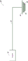
figure 1 illustrates a reduced-pressure wound treatment system according to some embodiments.
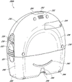
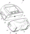
Fig. 2A-2C illustrate a pump assembly and a canister according to some embodiments.
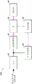
Fig. 3A-3C illustrate block diagrams of components of a pump assembly according to some embodiments.
Fig. 4 illustrates a process of providing an indication of congestion in accordance with some embodiments.
Fig. 5A-5C show plots illustrating when an activity level of a pump according to some embodiments may indicate an occlusion.
FIG. 6 shows a plot illustrating the effect of a flow control valve in a fluid flow path, according to some embodiments.
FIG. 7 shows a plot illustrating the effect of flow control valves at various positions in a fluid flow path, according to some embodiments.
Fig. 8A-8B and 9A-9B show exemplary plots illustrating when the activity level of a pump according to some embodiments may indicate an occlusion.
Detailed Description
SUMMARY
Embodiments disclosed herein relate to systems and methods for treating wounds using reduced pressure. As used herein, a reduced or negative pressure level, such as-X mmHg, represents a pressure level relative to normal ambient atmospheric pressure, which may correspond to 760mmHg (or 1 atm, 29.93 inHg, 101.325 kPa, 14.696 psi, etc.). Accordingly, the negative pressure value of-X mmHg reflects a relative pressure lower than 760mmHg by X mmHg, or in other words, reflects an absolute pressure of (760-X) mmHg. Further, a negative pressure that is "less than" or "less than" X mmHg corresponds to a pressure that is closer to atmospheric pressure (e.g., -40mmHg less than-60 mmHg). A negative pressure "greater than" or "greater than" -X mmHg corresponds to a pressure further away from atmospheric pressure (e.g., -80mmHg greater than-60 mmHg). In some embodiments, the local ambient atmospheric pressure is used as a reference point, and such local atmospheric pressure may not necessarily be, for example, 760 mmHg.
Embodiments of the present disclosure are generally suitable for use in a Topical Negative Pressure (TNP) or reduced pressure treatment system. In short, negative pressure wound therapy facilitates closure and healing of many forms of "refractory" wounds by reducing tissue edema, promoting blood flow and granular tissue formation, or removing excess exudate, and can reduce bacterial loads (and thus, reduce infection risk). Furthermore, such treatment allows less interference with the wound, resulting in a more rapid healing. TNP therapy systems can also aid in the healing of surgically closed wounds by removing fluid. In some embodiments, TNP treatment helps stabilize the tissue in a closed, aligned position. Another beneficial use of TNP therapy can be found in grafts and flaps where removal of excess fluid is important and where close proximity of the graft to the tissue is required in order to ensure tissue viability.
Negative pressure system
Fig. 1 illustrates an embodiment of a negative or reduced pressure wound treatment (or TNP) system 100 that includes a wound filler 130 placed within a wound cavity 110, the wound cavity 110 being sealed by a wound cover 120. The wound filler 130 in combination with the wound cover 120 may be referred to as a wound dressing. A single or multi-lumen tube or conduit 140 connects the wound cover 120 with a pump assembly 150 configured to supply reduced pressure. The wound cover 120 may be in fluid communication with the wound cavity 110. In any of the system embodiments disclosed herein, as in the embodiment shown in fig. 1, the pump assembly may be a canister-less pump assembly (meaning exudate is collected in the wound dressing or transferred via tubing 140 for collection to another location). However, any of the pump assembly embodiments disclosed herein can be configured to include or support a canister. Further, in any of the system embodiments disclosed herein, any of the pump assembly embodiments can be mounted to or supported by or adjacent to the dressing. The wound filler 130 may be of any suitable type, such as hydrophilic or hydrophobic foam, gauze, an air-filled bag, and the like. The wound filler 130 may conform to the wound cavity 110 such that it substantially fills the cavity. The wound cover 120 may provide a substantially fluid impermeable seal over the wound cavity 110. Wound cover 120 may have a top side and a bottom side, and the bottom side is adhesively (or in any other suitable manner) sealed with wound cavity 110. The catheter 140 or lumen or any other catheter or lumen disclosed herein may be formed of polyurethane, PVC, nylon, polyethylene, silicone, or any other suitable material.
Some embodiments of the wound cover 120 may have a port (not shown) configured to receive an end of the conduit 140. In other embodiments, the conduit 140 can otherwise pass through or under the wound cover 120 to supply reduced pressure to the wound cavity 110 in order to maintain a desired level of reduced pressure in the wound cavity. The conduit 140 may be any suitable article configured to provide an at least substantially sealed fluid flow path between the pump assembly 150 and the wound cover 120 for supplying reduced pressure provided by the pump assembly 150 to the wound cavity 110.
The wound cover 120 and the wound filler 130 may be provided as a single article or as an integral, single unit. In some embodiments, no wound filler is provided, and the wound cover itself may be considered a wound dressing. The wound dressing may then be connected to a source of negative pressure, such as a pump assembly 150, via conduit 140. The pump assembly 150 can be miniaturized and portable, but larger conventional pumps can also be used.
Some embodiments of the system are designed to operate without the use of an exudate canister. Some embodiments may be configured to support an exudate canister. In some embodiments, configuring the pump assembly 150 and the conduit 140 such that the conduit 140 can be quickly and easily removed from the pump assembly 150 can facilitate or improve the process of dressing or pump change, if desired. Any of the pump embodiments disclosed herein can be configured to have any suitable connection between the tubing and the pump.
In some embodiments, the pump assembly 150 can be configured to deliver a negative pressure of about-80 mmHg, or between about-20 mmHg and-200 mmHg. Note that these pressures are relative to normal ambient atmospheric pressure, so in practice-200 mmHg may be about 560mmHg in practice. The pressure may range from about-40 mmHg to-150 mmHg. Alternatively, pressure ranges up to-75 mmHg, up to-80 mmHg, or above-80 mmHg can also be used. Pressure ranges below-75 mmHg may also be used. Alternatively, a pressure range in excess of about-100 mmHg or even 150mmHg may be supplied by the pump assembly 150.
In some embodiments, the pump assembly 150 is configured to provide continuous or intermittent negative pressure therapy. Continuous treatment can be delivered at greater than-25 mmHg, -40mmHg, -50mmHg, -60mmHg, -70mmHg, -80mmHg, -90mmHg, -100mmHg, -120mmHg, -140mmHg, -160mmHg, -180mmHg, -200mmHg, or less than-200 mmHg. Intermittent therapy may be delivered between a low negative pressure set point and a high negative pressure set point. The low set point can be set above 0mmHg, -25mmHg, -40mmHg, -50mmHg, -60mmHg, -70mmHg, -80mmHg, -90mmHg, -100mmHg, -120mmHg, -140mmHg, -160mmHg, -180mmHg, or below-180 mmHg. The high set point can be set above-25 mmHg, -40mmHg, -50mmHg, -60mmHg, -70mmHg, -80mmHg, -90mmHg, -100mmHg, -120mmHg, -140mmHg, -160mmHg, -180mmHg, -200mmHg, or below-200 mmHg. During the intermittent treatment, negative pressure at the low set point may be delivered for a first duration, and upon expiration of the first duration, negative pressure at the high set point may be delivered for a second duration. At the expiration of the second duration, the negative pressure at the low set point may be delivered. The first and second durations may be the same or different values. The first and second durations may be selected from the following ranges, namely: less than 2 minutes, 3 minutes, 4 minutes, 6 minutes, 8 minutes, 10 minutes, or greater than 10 minutes. In some embodiments, switching between low and high set points and vice versa may be performed in a stepped waveform, a square waveform, a sinusoidal waveform, and the like.
In operation, the wound filler 130 is inserted into the wound cavity 110 and the wound cover 120 is placed to seal the wound cavity 110. The pump assembly 150 provides a source of negative pressure to the wound cover 120, which is transmitted to the wound cavity 110 via the wound filler 130. Fluid (e.g., wound exudate) is drawn through the conduit 140 and may be stored in a canister. In some embodiments, the fluid is absorbed by the wound filler 130 or one or more absorbent layers (not shown).
Wound Dressings that may be used with the pump assembly and other embodiments of the present application include Renasys-F, Renasys-G, Renasys AB, and Pico Dressings available from Smith & Nephew. Additional descriptions of other components of such wound dressings and negative pressure wound therapy systems that may be used with the pump assembly and other embodiments of the present application are found in U.S. patent publication nos. 2011/0213287, 2011/0282309, 2012/0116334, 2012/0136325, and 2013/0110058, which are incorporated by reference herein in their entirety. In other embodiments, other suitable wound dressings may be utilized.
Pump assembly and canister
Fig. 2A illustrates a front view 200A of a pump assembly 230 (such as pump assembly 150) and a canister 220, according to some embodiments. As illustrated, the pump assembly 230 and the canister 220 are connected, thereby forming a device. The pump assembly 230 includes one or more indicators, such as a visual indicator 202 configured to indicate an alarm and a visual indicator 204 configured to indicate a status of the TNP system. Indicators 202 and 204 may be configured to notify a user (e.g., a patient or medical care provider) of various operational or fault conditions of the system, including notifying a user of a normal or proper operational state, a pump failure, a failure of power or power supplied to the pump, detection of a leak in the wound cover or flow path, an inhalation blockage, or any other similar or suitable condition, or combinations thereof. The pump assembly 230 can include additional indicators. The pump assembly may use a single indicator or multiple indicators. Any suitable indicator may be used, such as visual, audio, tactile, and the like. The indicator 202 may be configured to signal an alarm condition, such as a canister full, low power, conduit 140 broken, seal break in the wound seal 120, and the like. The indicator 202 may be configured to display a red flash to attract the attention of the user. The indicator 204 may be configured to signal the state of the TNP system, e.g., that therapy delivery is good, that a leak is detected, etc. The indicator 204 may be configured to display one or more different colors of light, such as green, yellow, and the like. For example, a green light may be emitted when the TNP system is operating normally and a yellow light may be emitted to indicate a warning.
The pump assembly 230 includes a display or screen 206 mounted in a recess 208 formed in the housing of the pump assembly. The display 206 may be a touch screen display. The display 206 may support playback of Audiovisual (AV) content, such as instructional video. As explained below, the display 206 may be configured to render a number of screens or Graphical User Interfaces (GUIs) for configuring, controlling and monitoring the operation of the TNP system. The pump assembly 230 includes a grip portion 210 formed in a housing of the pump assembly. The grip portion 210 may be configured to assist a user in gripping the pump assembly 230, for example during removal of the canister 220. For example, when the canister 220 is filled with fluid, the canister 220 may be replaced with another canister.
The pump assembly 230 includes one or more keys or buttons 212 configured to allow a user to operate and monitor the operation of the TNP system. As shown, buttons 212a, 212b, and 212c are included. The button 212a may be configured as a power button to turn the pump assembly 230 on/off. Button 212b may be configured as a run/pause button for delivering negative pressure therapy. For example, pressing button 212b may cause treatment to begin, and then pressing button 212b may cause treatment to pause or end. Button 212c may be configured to lock display 206 or button 212. For example, button 212c may be pressed so that the user does not inadvertently change the delivery of therapy. Button 212c may be pressed to unlock the controls. In other embodiments, additional buttons may be used, or one or more of the illustrated buttons 212a, 212b, or 212c may be omitted. A plurality of keys or key sequences may be used to operate the pump assembly 230.
The pump assembly 230 includes one or more latch recesses 222 formed in the cover. In the illustrated embodiment, two latch recesses 222 can be formed on the side of the pump assembly 230. The latch recess 222 may be configured to allow the use of one or more tank latches 221 to attach and detach the tank 220. The pump assembly 230 includes an air outlet 224 for allowing air removed from the wound cavity 110 to escape. Air entering the pump assembly may pass through one or more suitable filters, such as an antimicrobial filter or the like. This may maintain the reusability of the pump assembly. The pump assembly 230 includes one or more strap mounts 226 for connecting the carrier strap to the pump assembly 230 or for attaching a bracket. In the illustrated embodiment, two band mounts 226 may be formed on the sides of the pump assembly 230. In some embodiments, various of these features are omitted, or various additional features are added to the pump assembly 230.
The canister 220 is configured to contain fluid (e.g., exudate) removed from the wound cavity 110. The canister 220 includes one or more latches 221 for attaching the canister to the pump assembly 230. In the illustrated embodiment, the canister 220 includes two latches 221 on the sides of the canister. The exterior of the can 220 may be formed of frosted plastic such that the can is substantially opaque and the contents of the can are substantially hidden from plan view. The canister 220 includes a grip portion 214 formed in the housing of the canister. The gripping portion 214 may be configured to allow a user to grip the pump assembly 220, for example during removal of the canister from the device 230. The canister 220 includes a substantially transparent window 216, which may also include a scale for volume. For example, the illustrated 300mL canister 220 includes graduations of 50mL, 100mL, 150mL, 200mL, 250mL, and 300 mL. Other embodiments of the canister may contain different volumes of fluid and may include different scales. For example, the canister may be an 800mL canister. The canister 220 includes a conduit channel 218 for connection to the conduit 140. In some embodiments, various of these features, such as the grip portion 214, are omitted, or various additional features are added to the canister 220. Any of the disclosed canisters may include or may omit a curing agent.
Fig. 2B illustrates a rear view 200B of the pump assembly 230 and the canister 220, according to some embodiments. The pump assembly 230 includes a speaker port 232 for generating sound. The pump assembly 230 includes a filter access door 234 for accessing and replacing one or more filters (e.g., antimicrobial filters). The pump assembly 230 includes a grip portion 236 formed in a housing of the pump assembly 230. The gripping portion 236 may be configured to allow a user to grip the pump assembly 230, for example during removal of the canister 220. The pump assembly 230 includes one or more covers 238 configured as threaded covers or feet or protectors for placing the pump assembly 230 on a surface. The cover 230 may be formed of rubber, silicone, or any other suitable material. The pump assembly 230 includes a power jack 239 for charging and recharging the internal battery of the pump assembly. Power jack 239 may be a Direct Current (DC) jack. In some embodiments, the pump assembly 230 may include a disposable power source, such as a battery, so that a power jack is not required.
The tank 220 includes one or more feet 244 for placing the tank on a surface. The feet 244 may be formed of rubber, silicone, or any other suitable material, and may be angled at a suitable angle so that the canister 220 remains stable when placed on a surface. The canister 220 includes a tube mounting relief (tube mount relief) 246 configured to allow one or more tubes to exit to the front of the device. The canister 220 includes a stand or support 248 for supporting the canister when it is placed on a surface. As explained below, the seat 248 may pivot between an open position and a closed position. In the closed position, the seat 248 may be latched to the canister 220. In some embodiments, the standoffs 248 may be made of an opaque material, such as plastic. In other embodiments, the standoffs 248 can be made of a transparent material. The seat 248 includes a gripping portion 242 formed therein. The grip portion 242 may be configured to allow a user to place the seat 248 in a closed position. The holder 248 includes an aperture 249 to allow a user to place the holder in an open position. The hole 249 may be sized to allow a user to pull out the holder using a finger.
Fig. 2C illustrates a view 200C of the pump assembly 230 separated from the canister 220, according to some embodiments. The pump assembly 230 includes a vacuum attachment, connector or inlet 252 through which a vacuum pump communicates negative pressure to the canister 220. The pump assembly draws fluid, such as gas, from the wound via the inlet 252. The pump assembly 230 includes a USB access door 256 configured to allow access to one or more USB ports. In some embodiments, the USB access gate is omitted and the USB port is accessed through gate 234. The pump assembly 230 may include additional access doors configured to allow access to additional serial, parallel, or hybrid data transfer interfaces, such as SD, Compact Disc (CD), DVD, FireWire, Thunderbolt, PCI Express, and the like. In other embodiments, one or more of these additional ports are accessed through the gate 234.
Additional description of the pump assembly 230 is disclosed in U.S. patent publication No. 2015/0025482, which is incorporated herein by reference in its entirety.
Pump assembly component
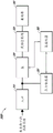
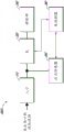
Fig. 3A illustrates a block diagram of certain components 300A of a pump assembly, such as the pump assembly 150, according to some embodiments. The component 300A includes an inlet 310 (such as inlet 252), a flow control valve 320, a pump 330, a drain 340, a pressure sensor 350, and a pump controller 360.
The pump controller 360 may control the operation of the pump 330. The pump 330 may provide negative pressure in a fluid flow path connecting the inlet 310, the flow control valve 320, and the pump 330 such that negative pressure is provided to the inlet 310 and then to the wound (e.g., through the canister). The pump 330 may be a suitable pump such as a diaphragm pump, a peristaltic pump, a rotary vane pump, a scroll pump, a screw pump, a liquid ring pump, a diaphragm pump operated by a piezoelectric transducer, a voice coil pump, or the like. The flow control valve 320 may be a valve such as a non-return valve, such as those commercially available from Value Plastics, inc. In the illustration of fig. 3A, the flow control valve 320 may allow fluid to flow in a fluid flow path from the inlet 310 to the drain 340, but not from the drain 340 to the inlet 310.
In some embodiments, the pump controller 360 can measure the pressure near the inlet 310 or at the inlet 310 (or at any other location in the fluid flow path, such as at a wound) in the fluid flow path using data received from one or more pressure sensors (such as pressure sensor 350), calculate the fluid flow rate, and control the pump. In some embodiments, the pump controller 360 controls an actuator, such as a pump motor of the pump 330, such that a desired level of negative pressure is achieved in the wound cavity 110. The desired negative pressure level (or negative pressure set point) may be a pressure set or selected by a user. In various embodiments, pump controller 360 uses Pulse Width Modulation (PWM) to control pump 330, such as by controlling a pump motor of pump 330 using PWM. The control signal for driving the pump 330 may be a PWM signal with a 0-100% duty cycle. The pump controller 360 can perform flow rate calculations and detect alarm conditions. The pump controller 360 can include an internal memory (not shown) or utilize an external memory (not shown), and the pump controller 360 can be a low power processor.
In some embodiments, pump controller 360 can control pump 330, perform flow rate calculations, or detect an alarm condition in at least some cases without measuring or using measurements of pressure in the fluid flow path or without using measurements output by pump 330 (such as in response to rotation of the pump motor of the pump, a signal from an internal tachometer of pump 330). For example, without measuring or using the pressure measured in the fluid flow path, the pump controller 360 may, at least in some cases, use at least or only the activity level of the pump 330 to control the pump 330, perform a flow rate calculation, or detect an alarm condition. As another example, the pump controller 360 can use at least or only a measurement of pressure in the fluid flow path to control the pump 330, perform a flow rate calculation, or detect an alarm condition without determining or using a determined activity level of the pump. This may be performed, for example, by comparing the magnitude of the detected pressure signal to one or more thresholds (such as an occlusion threshold) to determine an occlusion or obstruction in the fluid flow path. One or more pulses detected or sensed by the pressure sensor may be determined to exceed (or meet or fall below) the occlusion threshold. When the number of such pulses meets a threshold (such as exceeding, becoming equal to, or falling below), an occlusion may be determined. Another state may be the time between pulses that meet the occlusion threshold. When such times meet a threshold (such as exceeding, becoming equal to, or falling below), congestion may be determined. Using the activity level of the pump to determine or estimate flow may be contrasted with directly measuring the flow rate (such as using a flow meter). In various embodiments, a canister full, leak, etc. may additionally or alternatively be determined.
The component 300A may further include one or more additional sensors (not shown), such as a tachometer, positioned to detect or determine the activity level of the pump 330 and provide an indication to the pump controller 360 in response to the activity level of the pump 330. For example, a tachometer may be separate from the pump 330 (e.g., external to the pump) and positioned near or coupled to the pump 330, and the tachometer may detect rotation (such as partial rotation, full rotation, or multiple partial or full rotations) of the pump motor of the pump 330. The tachometer can output a signal (or signals) to the pump controller 360 that provides an indication, such as a pulse (e.g., a high signal indication in a series of other low signal indications), in response to rotation of the pump motor. In some implementations, the tachometer may be a hall effect sensor or an opto-isolator sensor.
The pump controller 360 performs flow rate monitoring for the fluid flow path using the indications from the one or more additional sensors. The pump controller 360 can continuously or periodically monitor the indication from the one or more additional sensors to monitor the flow rate. For example, the pump controller 360 may receive a signal including an indication from a tachometer and thereby determine a rotational speed (sometimes referred to as an operating speed) of a pump motor of the pump 330. If the rotational speed can be below a certain level, at a certain level, or above a certain level, for example, it can be determined that a blockage (sometimes referred to as a restricted volume condition) can exist in the fluid flow path. The blockage may be due to blockage in the tube or lumen, canister filling, or the like. In such a case, the alarm may be triggered by the pump controller 360, and the pump controller 360 may wait for the user to take one or more actions to resolve the occlusion. In some embodiments, pump controller 360 can use an indication responsive to the activity level of pump 330 to control the pump, perform a flow rate calculation, or detect an alarm condition, at least in some cases, without using a measurement of pressure in the fluid flow path or without using a measurement output by pump 330.
Fig. 3B illustrates a block diagram of certain components 300B of a pump assembly, such as the pump assembly 150, according to some embodiments. The component 300B may be the same as the component 300A of fig. 3A, except that the positions of the flow control valve 320 and the pump 330 in the fluid flow path may be swapped. Accordingly, the flow control valve 320 may be positioned at the discharge portion side of the pump 330 in the fluid flow path as shown in fig. 3B, instead of the inlet side of the pump 330 in the fluid flow path as shown in fig. 3A.
Fig. 3C illustrates a block diagram of components 300C of a pump assembly, such as the pump assembly 150, according to some embodiments. The component 300C may be the same as the component 300A of fig. 3A, except that the flow control valve 320 may not be included in the fluid flow path as shown in fig. 3C. In some embodiments, the flow control valve may be integrated into the pump 330.
Occlusion detection
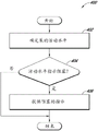
Fig. 4 illustrates a process 400 of providing an indication of a blockage in a fluid flow path, according to some implementations. The process 400 may be performed, for example, by the pump controller 360. The process 400 may be performed continuously or periodically or at any other suitable frequency. Advantageously, in certain embodiments, the process 400 may enable providing an indication of an occlusion in the fluid flow path to detect the occlusion without using the pressure in the fluid flow path or without using measurements output by the pump.
At block 402, the process 400 may determine an activity level of a pump (such as the pump 330). The activity level of the pump may be determined continuously or periodically or at any other suitable frequency. In one example, the activity level of the pump may be determined from the activity level of a pump motor of the pump, which is detected by a sensor (such as a tachometer). The tachometer may detect rotation of the pump motor and provide a signal in response thereto, the signal including an indication, such as a pulse. In another example, the activity level of the pump may be determined using a PWM signal for driving the pump motor, a coded signal output by the pump, or a pressure in the fluid flow path. In some embodiments, one or more of these or other determinations may be combined to calculate the activity level.
In some embodiments, the activity level of the pump may be determined using a signal (e.g., a signal output by a tachometer) by determining whether one or more conditions have been met or satisfied. In some embodiments, one or more of the following may be determined: (1) a duration between consecutive features of the signal, (2) a plurality of durations between a plurality of features of the signal, (3) a change in time between features of the signal (e.g., an averaging period), (4) a count of the number of features of the signal for which the duration between consecutive features of the signal exceeds (or meets or falls below) a threshold, and (5) a time range between features of the signal. The characteristics of the signal (sometimes referred to as pulses) may be, for example, one or more of a rising edge of the signal, a falling edge of the signal, a peak of the signal, and a valley of the signal. In another example, the activity level of the pump may be determined from a PWM signal used to drive the pump motor or a coded motor signal output by the pump. In some embodiments, the process 400 may further determine a change in activity level of the pump over time at block 402. The change in the activity level of the pump may be determined continuously or periodically or at any other suitable frequency. In some embodiments, the activity level or the change in activity level may be further processed, such as averaging, filtering, and the like.
At block 404, the process 400 may determine whether the activity level of the pump indicates a blockage in the fluid flow path. The fluid flow path may provide fluid communication between a wound dressing (such as wound cover 120) and a pump, and the occlusion may be a condition indicating a substantially full canister or dressing, or the canister or dressing filter may be clogged or occluded. In one example, the activity level of the pump may indicate occlusion when the activity level or a change in the activity level of the pump meets (e.g., meets, falls below, or exceeds) one or more thresholds or matches one or more patterns, such as (i) a certain number of the final total number of pulses of the signal exceeds a limit, (ii) a long delay of repetition in a pulse of the signal followed by a short delay in one or more pulses of the signal, or (iii) a value tracked by and responsive to a pulse of the signal by a processor, such as the pump controller 360, remains constant or substantially constant (e.g., the signal becomes saturated because the frequency in the pulse of the signal is so low that the data collection capability of the sensor(s) or processor prevents the processor from further adjusting the value). In another example, the activity level of the pump may indicate an occlusion when the activity level shows increased instability in the operation of the pump. Increased instability may be evidenced, for example, in pump control behavior as the pump repeatedly exceeds, decays from, or accelerates from the pump control set point. As another example, as explained herein, increased instability may be evidenced via an unstable level of pump activity, such as when a measured change in pump activity meets (such as exceeds or falls below) a threshold.
Exemplary activity levels or changes in activity levels of a blocked pump over time that may or may not be indicated are described at least with respect to fig. 5A-5C. Changes in activity level of an obstructed pump over time, or other exemplary activity levels, which may or may not be indicated, will be apparent from reviewing at least the exemplary levels described or the changes described herein.
If the activity level of the pump over time does not indicate an occlusion in the fluid flow path, the process 400 may end, or in some embodiments, one or more other checks may be performed using different methods to determine if an occlusion exists. On the other hand, if the activity level of the pump over time indicates a blockage in the fluid flow path, the process 400 may move to block 406. At block 406, the process 400 may provide an indication of the blockage. The indication of occlusion may for example comprise activating an alarm indicating occlusion. The alarm may then guide the user to investigate or resolve the blockage. In some cases, the indication of congestion may represent a potential congestion state rather than a definite indication of a congestion state. In some embodiments, process 400 may also perform one or more other checks using different methods to confirm the presence of a blockage. In another example, the indication of an occlusion may include changing a mode of operation of the pump, such as deactivating the pump, triggering a countdown timer for deactivating the pump if the occlusion is not resolved within a time period, or increasing or decreasing a level of activity of the pump.
In some embodiments, performing process 400 may provide one or more different advantages. In one example, the process 400 may be desired for use with a pump or pump controller that is relatively inexpensive, simple, or has limited capabilities. This may be because process 400 may use relatively straightforward techniques (e.g., determining the duration between features of the signal, counting the features of the signal, and then comparing the duration or count to a threshold, or detecting saturation in the tracked values for a period of time in response to a pulse of the signal) to determine whether to provide an occlusion indication, and thus may be included in a relatively inexpensive and simple pump or pump controller. In another example, the use process 400 may be desirable because a pump assembly (such as the pump assembly 150) may not include a pressure sensor (such as the pressure sensor 350) to determine whether to provide an indication of an occlusion, or may not include a pump that outputs a signal indicative of an activity level of the pump. Accordingly, the cost of the pump assembly can be reduced, and the size of the pump assembly can also be reduced. In yet another example, using process 400 may be desirable for increasing the accuracy or robustness of determining whether to provide an indication of congestion. The process 400 may be used, for example, in combination with or independent of one or more other occlusion determinations (e.g., occlusion determinations based on pressure measurements, weight measurements, or optical detection in a fluid flow path or tank) to make a final determination of whether to provide an indication of occlusion. Process 400 may also be advantageous because process 400 may detect an occlusion when one or more other occlusion determinations may fail to detect an occlusion. For example, when performing other processing (e.g., averaging) on measurements from sensors that detect the activity level (e.g., operating speed) of the pump, such processing may smooth or mask an occlusion from being noticed from the processed signal, which may be readily detected using the methods provided herein. In one illustration, six tachometer pulses every 60 seconds may yield the same calculated average as five tachometer pulses separated by 180 seconds, 20 seconds, 40 seconds, 60 seconds, and 60 seconds, respectively. However, the five tachometer pulses may indicate an occlusion as described herein, while the six tachometer pulses may not indicate an occlusion. In some embodiments, the process 400 may distinguish between various types of occlusion states, such as distinguishing between canister (or dressing) filling and occlusions in other portions of the flow path.
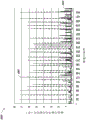
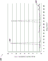
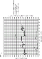
Fig. 5A shows an exemplary plot 500A illustrating when an activity level of a pump (such as pump 330) may indicate an occlusion according to some embodiments. Plot 500A may be a plot for a pump assembly (such as pump assembly 230) that includes components 300A, 300B, or 300C discussed with respect to fig. 3A-3C, and a tachometer configured to provide pulses indicative of rotation of a pump motor of the pump. The y-axis of plot 500A provides the time between consecutive tacho pulses in seconds, and the x-axis of plot 500A provides the assigned number for about 450 consecutive tacho pulses. Curve 502A illustrates data obtained for a flow path without a blockage, while curve 504A illustrates data obtained from a flow path with a blockage.
Fig. 5B shows an exemplary plot 500B illustrating when an activity level of a pump (such as pump 330) may indicate an occlusion according to some embodiments. Plot 500B may be a plot for a pump assembly (such as pump assembly 230) that includes components 300A, 300B, or 300C discussed with respect to fig. 3A-3C, and a tachometer configured to provide pulses indicative of rotation of a pump motor of the pump. The y-axis of plot 500B provides the time between consecutive tacho pulses in seconds, and the x-axis of plot 500B provides the assigned number for about 50 consecutive tacho pulses (as opposed to about 450 pulses in fig. 5A). Curve 502B illustrates data obtained for a flow path without a blockage, while curve 504B illustrates data obtained from a flow path with a blockage.
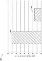
Fig. 5C shows an exemplary plot 500C illustrating when the activity level of a pump according to some embodiments may indicate an occlusion. Plot 500C may be a plot for a pump assembly (such as pump assembly 230) that includes components 300A, 300B, or 300C discussed with respect to fig. 3A-3C, and a tachometer configured to provide pulses indicative of rotation of a pump motor of the pump. The y-axis of plot 500C provides the minimum observed time between tachometer pulses in seconds, and the x-axis of plot 500C shows either a restricted or empty tank condition. Curve 502C illustrates data obtained for a flow path without a blockage, while curve 504C illustrates data obtained from a flow path with a blockage.
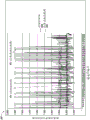
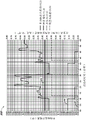
Fig. 6 shows an exemplary plot 600 illustrating the effect of a flow control valve in a fluid flow path on a detected signal that may be used to determine an activity level of a pump according to some embodiments. The plot 600 may be a plot for a pump assembly (such as the pump assembly 230) that includes the component 300A or 300B with the line of flow control valves and the component 300C without the line of flow control valves, and a tachometer configured to provide pulses indicative of rotation of a pump motor of the pump. The y-axis of plot 600 provides the time between consecutive tacho pulses in seconds, and the x-axis of plot 600 provides the assigned number for about 850 consecutive tacho pulses. Plot 602 illustrates data obtained for a pump assembly without a flow control valve, while plot 604 illustrates data obtained for a pump assembly with a flow control valve. Plot 600 further depicts a moving average for curves 602, 604, which may be processed in addition to curves 602, 604 or instead of curves 602, 604 in some embodiments.
The plot 600 illustrates, for example, how including a flow control valve in a fluid flow path may, in certain embodiments, result in more stable pump activity and, in turn, more stable or accurate measurements from a sensor, such as a tachometer, positioned to detect or determine a level of activity of the pump. Further, in addition to the flow direction control benefits of the flow control valve, the flow control valve may reduce pressure waves in the fluid flow path by providing a pressure drop and acting as a low pass filter for the pressure signal traveling to the pump. The inclusion of a flow control valve may further help prevent nuisance to the user due to false activation of the pump assembly alarm. In various embodiments, the duration between non-consecutive pulses may be utilized. In some embodiments, a measure of the change in activity level of the pump, such as an average tachometer period, may be used in addition to or in place of the duration between features of the activity level (such as the duration between consecutive tachometer pulses). This is described, for example, in connection with fig. 8A-8B and 9A-9B.
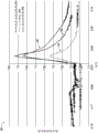
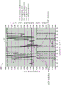
Fig. 7 shows an exemplary plot 700 illustrating the effect of flow control valves at various positions in a fluid flow path on a detected signal that may be used to determine an activity level of a pump according to some embodiments. The plot 700 may be a plot for a pump assembly (such as the pump assembly 230) that includes an arrangement of the component 300A in the case of a line 704 for an inlet-side valve, an arrangement of the component 300B in the case of a line 706 for a drain-side valve, an arrangement of the component 300C in the case of a line 702 without a flow control valve, and a tachometer configured to provide pulses indicative of rotation of a pump motor of the pump. The y-axis of plot 700 provides pressure sensor voltage for a pressure sensor (such as pressure sensor 350), and the x-axis of plot 700 provides time.
The plot 700 illustrates, for example, how, in certain embodiments, including a flow control valve in the fluid flow path results in a damped or reduced pressure wave (e.g., by providing a pressure drop and acting as a low pass filter for the pressure signal traveling to the sensor). As illustrated by diagram 704 (which corresponds to the arrangement of components 300A of fig. 3A), including a flow control valve at the inlet may advantageously reduce pressure waves and result in more accurate, stable, larger signal amplitude measurements from one or more sensors, such as activity sensors (e.g., tachometers), as compared to other arrangements or combinations of components. As explained in connection with fig. 8A-8B and 9A-9B, this may provide improved discrimination during processing of the sensed signals. The inclusion of a flow control valve may further help prevent nuisance to the user due to false activation of the pump assembly alarm.
Occlusion detection using clamping status detection
Fig. 8A shows an exemplary plot 800A illustrating when an activity level of a pump (such as pump 330) may indicate an occlusion according to some embodiments. Plot 800A may be a plot for a pump assembly (such as pump assembly 230) that includes component 300C discussed with respect to fig. 3C, and a tachometer configured to provide pulses indicative of rotation of a pump motor of the pump. The pump assembly may be operated at a set point of-40 mmHg. The y-axis of plot 800A provides the average time period (or frequency) between consecutive tachometer pulses in seconds (scale to the left), the mass flow measurement in Standard Liters Per Minute (SLPM) (scale to the right), and a scaled alarm (scaled alarm) indication (high corresponding to "on"). The x-axis of plot 800A provides elapsed time in minutes. Plot 800A depicts an average tachometer cycle 802, a choke threshold setting 804, a mass flow measurement 806 (e.g., a flow rate directly measured using a flow meter, such as a mass flow meter), and a measured alarm 808 over time. A weighted alarm 808, when high, may indicate an alarm state, such as a blocked state. The measured alarm 808 may be, for example, (i) used to activate and deactivate an alarm, which may be audible or visually perceptible, (ii) an alarm flag in memory, or (iii) include or trigger a change in operation of the pump.
The plot 800A, for example, illustrates how the measured alarm 808 may not be activated when the average tachometer period 802 does not meet the occlusion threshold 804. As can be seen, the average tachometer period 802 remains below the occlusion threshold 804 such that the measured alarm 808 remains deactivated. However, the mass flow measurement 806 illustrates little to no flow in the fluid flow path, which is indicative of a blockage condition.
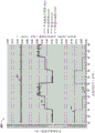
Fig. 8B shows an exemplary plot 800B illustrating when an activity level of a pump (such as pump 330) may indicate an occlusion according to some embodiments. Plot 800B may be a plot for a pump assembly (such as pump assembly 230) that includes component 300A discussed with respect to fig. 3A, and a tachometer configured to provide pulses indicative of rotation of a pump motor of the pump. The pump assembly may be operated at a set point of-40 mmHg. The y-axis of plot 800B provides the average time period between consecutive tachometer pulses in seconds (scale to the left), the mass flow measurement in SLPM (scale to the right), and the measured alarm indication (high corresponds to "on"). The x-axis of plot 800B provides elapsed time in minutes. Plot 800B depicts average tachometer cycle 812, occlusion threshold setting 814, pinch status threshold 815, mass flow measurement 816, and measured alarm 818 over time. A weighted alarm 818, when high, may indicate an alarm state, such as a blocked state. The measured alarm 818 may be, for example, (i) used to activate and deactivate an alarm, which may be audible or visually perceptible, (ii) an alarm flag in memory, or (iii) include or trigger a change in operation of the pump. The average tachometer period 812 has a larger, more accurate amplitude or dynamic range than the average tachometer period 802 of fig. 8A (which is obtained from a pump that does not include a fluid control valve), such that the accuracy of processing and detection is improved. In some embodiments, the time period between consecutive tachometer pulses (such as in fig. 5A-5C and 6, for example) or other measurements of activity level may be utilized instead of or in addition to the average tachometer period.
The plot 800B illustrates how a measured alarm 818 may be activated, for example, when an average tachometer cycle 812 meets at least one of a jam threshold setting 814 or a clamp status threshold setting 815 instantaneously or for a period of time (e.g., 10 seconds, 20 seconds, 30 seconds, 45 seconds, 1 minute, 1.5 minutes, 2 minutes, 3 minutes, etc.). As can be seen, the measured alarm 818 may not be activated at about 4 minutes because the average tachometer period 812 may not have met the jam threshold setting 814 or the clamp status threshold setting 815. On the other hand, when the average tachometer cycle 812 satisfies the jam threshold setting 814, the measured alarm 818 may be activated at approximately 12 minutes and 17 minutes. Activation of the alarm 818 measured at approximately 12 minutes and 17 minutes may thus be used to trigger an occlusion threshold alarm. When the average tachometer cycle 812 no longer satisfies the jam threshold setting 814, the weighted alarm 818 that was activated at about 12 and 17 minutes may be deactivated at about 14 and 18 minutes. Further, when the average tachometer cycle 812 meets the clamped state threshold setting 815, the measured alarm 818 may be activated at about 23 minutes. Activation of the alarm 818 measured at about 23 minutes may thus be used to trigger a clamp status threshold alarm. When the average tachometer cycle 812 no longer satisfies one or both of the jam threshold setting 814 or the clamp status threshold setting 815, the weighted alarm 818 that was activated at about 23 minutes may be deactivated at about 32 minutes. This operation may be confirmed by mass flow measurements 816, which mass flow measurements 816 illustrate little to no flow in the fluid flow path, which is indicative of a blockage condition. Further, the mass flow measurement 816 at between about 0-10 minutes and between about 30-40 minutes may represent a minimum allowable flow rate for the pump assembly. Thus, an alarm during between about 0-10 minutes and between about 30-40 minutes may be considered a nuisance alarm. Further, the mass flow measurement 816 at between about 10-30 minutes and between about 40-60 minutes may be less than the minimum allowable flow for the pump assembly, so an alarm may be expected and triggered as described herein. After the alarm is triggered, the mass flow measurement 816 may return to a minimum allowable state, and the alarm may then be cleared, as illustrated at about 31 minutes.
The clamp status detection may be performed using a clamp status threshold setting 815, which clamp status threshold setting 815 may be a threshold for the pump that depends on the data collection capability of the pump. The pump may track a value, such as an average tachometer period 812 (or count of tachometer pulses, etc.), in response to the activity level of the pump. In some cases, however, the sensed indication of pump activity may become unreliable because the pump may be operated slowly due to a blockage in the flow path (e.g., the pump motor may run slowly). For example, due to an occlusion, the time between tachometer pulses may become so long that it meets (e.g., exceeds or falls below) a threshold value corresponding to a truncation for collecting meaningful data. This state may be referred to as recording a saturation value or reaching a "clamped state". The clamped state may be reached for a variety of reasons, including, for example, because one or more sensors or pump controllers of the pump (e.g., pump controller 360) are relatively inexpensive, simple, or have limited capabilities (e.g., processing speed, storage, etc.). In the clamped state, the determined value corresponding to the activity level may saturate and remain constant for a period of time, since the value may not be able to increase or decrease further (in other words, the value becomes saturated), even if the value should change further in response to the activity level of the pump, depending on the function used to adjust the value. Advantageously, in certain embodiments, saturation of such a value may provide an indication of an irregular condition for the pump, as well as an indication of a more reliable and faster occlusion than some other methods.
In one example, a pump controller of a pump may have the ability to track the activity level of the pump using values stored with 8-bit data (i.e., the activity level may be tracked using 256 levels of granularity (granularity) ranging from level 0 to level 255), where level 255 may indicate the lowest assigned activity level and level 0 may indicate the highest assigned activity level. In this example, the activity level of the pump may drop below the lowest dispensed activity level, and thus the pump controller may consider the activity level to remain at a 255 level even though the activity level has dropped below the lowest dispensed activity level. Thus, when the value remains at the 255 level and is therefore saturated, the saturation of the value may indicate an unconventional operating state for the pump and may be used as an alarm state indicating a blockage. In some embodiments, to prevent intermittent alarms (which may frustrate the user), once the value remains saturated for a period of time, such as 30 seconds, 1 minute, 2 minutes, etc., the saturation of the value may be considered an alarm condition.
In some embodiments, checking the gripping status using the gripping status threshold results in more accurate and reliable occlusion detection than using the occlusion threshold alone. This is because meeting the pinch threshold can reliably indicate that the pump is operating very slowly due to a permanent blockage in the fluid flow path. Conversely, relying solely on an occlusion threshold may result in less stable and less accurate detection, at least because the pump controller may not distinguish between (i) temporary occlusions (which may be cleared and should not trigger an occlusion alarm) and (ii) permanent occlusions in the fluid flow path. On the other hand, compliance with the grip state threshold, which is selected to signal very low activity of the pump compared to the occlusion threshold, may indicate that there is severe occlusion and that such occlusion is unlikely to be a temporary occlusion. Thus, when using the gripping state threshold, the occlusion state can be triggered more accurately and reliably. Although the plot 800B illustrates the simultaneous use of the occlusion threshold 814 and the clamp state threshold 815, the occlusion threshold 814 and the clamp state threshold 815 may each be implemented independently or without one threshold or another. Further, in some embodiments, the weighted alarms 808 and 818 may be used alone or in combination with one or more other states or indications (e.g., such as those disclosed herein) to determine whether to activate an alarm.
Fig. 9A shows an exemplary plot 900A illustrating when an activity level of a pump (such as pump 330) may indicate an occlusion according to some embodiments. Plot 900A may be a plot for a pump assembly (such as pump assembly 230) that includes component 300C discussed with respect to fig. 3C, and a tachometer configured to provide pulses indicative of rotation of a pump motor of the pump. The pump assembly may be operated at a set point of-120 mmHg. The y-axis of plot 900A provides the average time period between consecutive tachometer pulses in seconds (scale to the left), the mass flow measurement in SLPM (scale to the right), and the measured alarm indication (high corresponds to "on"). The x-axis of plot 900A provides elapsed time in minutes. Plot 900A depicts an average tachometer cycle 902, an occlusion threshold setting 904, a mass flow measurement 906, and a measured alarm 908 over time. A weighted alarm 908, when high, may indicate an alarm state, such as a blocked state. The measured alarms 908 may be, for example, (i) used to activate and deactivate alarms, which may be audible or visually perceptible, (ii) alarm flags in memory, or (iii) include altered operation of the pump.
Fig. 9B shows an exemplary plot 900B illustrating when an activity level of a pump (such as pump 330) may indicate an occlusion according to some embodiments. Plot 900B may be a plot for a pump assembly (such as pump assembly 230) that includes component 300A discussed with respect to fig. 3A, and a tachometer configured to provide pulses indicative of rotation of a pump motor of the pump. The pump assembly may be operated at a set point of-120 mmHg. The y-axis of plot 900B provides the average time period between consecutive tachometer pulses in seconds (scale to the left), the mass flow measurement in SLPM (scale to the right), and the measured alarm indication (high corresponds to "on"). The x-axis of plot 900B provides elapsed time in minutes. Plot 900B depicts average tachometer period 912, occlusion threshold setting 914, mass flow measurement 916, and measured alarm 918 over time. A weighted alarm 918 when high may indicate an alarm state, such as a blocked state. The measured alarms 918 may be, for example, (i) used to activate and deactivate alarms, which may be audible or visually perceptible, (ii) alarm flags in memory, or (iii) include or trigger altered operation of the pump. The average tachometer period 912 has a larger, more accurate amplitude or dynamic range than the average tachometer period 902 of fig. 9A (which is obtained from a pump that does not include a fluid control valve), so that the accuracy of processing and detection is improved.
The clamped state threshold is not illustrated in fig. 9B because it is set at an average tacho period that exceeds the maximum of 0.40 seconds on the y-axis (scale to the left). For example, the clamped state threshold setting 815 is set to about 0.825 seconds in fig. 8B. However, in some embodiments, the average tachometer period 912 is substantially less than the average tachometer period 812 because the negative pressure set point in FIG. 9B is set to a greater value (-120 mmHg) than the set point (-40 mmHg) in FIG. 8B, which results in the pump having a higher activity level (e.g., the pump motor runs faster) to reach and maintain the lower negative pressure set point. Thus, selecting the clamp state threshold for fig. 9B to be the same as or similar to the clamp state threshold setting 815 (which is selected for the lower negative pressure set point) may result in occlusion detection relying only on the occlusion threshold 914. Plot 900B illustrates, for example, how a measured alarm 918 may be activated when an average tachometer cycle 912 meets an occlusion threshold setting 914, either instantaneously or for a period of time (e.g., 10 seconds, 20 seconds, 30 seconds, 45 seconds, 1 minute, 1.5 minutes, 2 minutes, 3 minutes, etc.). As can be seen, the measured alarms 918 may be activated at approximately 12 and 42 minutes when the average tachometer cycle 912 satisfies the jam threshold setting 914 for the period of time. A weighted alarm 918 activated at approximately 12 and 42 minutes may thus be used to trigger an occlusion threshold alarm. When the average tachometer cycle 912 no longer meets the jam threshold setting 914, the weighted alarm 918 activated at about 12 and 42 minutes may thus be deactivated at about 31 minutes.
By comparing plots 800A and 800B with plots 900A and 900B, it can further be seen that as the set point increases, the average tachometer period is less likely to meet the grip state threshold because the average tachometer period may be less likely to increase to the level of the grip state threshold and reach saturation. In some embodiments, the grip state threshold may be selected from a plurality of grip state thresholds based at least on the negative pressure set point. For example, a decreasing value of the grip state threshold may be selected when the negative pressure set point increases. A similar selection for the occlusion threshold may be performed in various embodiments.
Other variants
Any values provided herein for thresholds, limits, durations, and the like, are not intended to be absolute, and thus may be approximate. Further, any thresholds, limits, durations, etc. provided herein may be fixed or changed automatically or by a user. Further, as used herein, relative terms such as over, greater than, less than, and the like with respect to a reference value are also intended to include being equal to the reference value. For example, exceeding the reference value as positive may include being equal to or greater than the reference value. Further, as used herein, relative terms such as above, greater than, less than, and the like with respect to a reference value are also intended to encompass an inverse of the disclosed relationship, such as below, less than, greater than, and the like with respect to the reference value.
Features, materials, characteristics or groups described in connection with a particular aspect, embodiment or example are to be understood as applicable to any other aspect, embodiment or example described herein unless incompatible therewith. All of the features disclosed in this specification (including any accompanying claims, abstract and drawings), or all of the steps of any method or process so disclosed, may be combined in any combination, except combinations where at least some of such features or steps are mutually exclusive. The protection is not restricted to the details of any of the foregoing embodiments. Any novel one, or any novel combination, of the features disclosed in this specification (including any accompanying claims, abstract and drawings), or any novel one, or any novel combination, of the steps of any method or process so disclosed, is/are protected.
While certain embodiments have been described, these embodiments have been presented by way of example only, and are not intended to limit the scope of protection. Indeed, the novel methods and systems described herein may be embodied in a variety of other forms. Furthermore, various omissions, substitutions and changes in the form of the methods and systems described herein may be made. Those skilled in the art will appreciate that in some embodiments, the actual steps taken in the illustrated or disclosed processes may differ from those shown in the figures. According to embodiments, some of the steps described above may be removed, and other steps may be added. For example, the actual steps or sequence of steps taken in the disclosed processes may differ from that shown in the figures. According to embodiments, some of the steps described above may be eliminated, and other steps may be added. For example, the various components shown in the figures may be implemented as software or firmware on a processor, controller, ASIC, FPGA, or dedicated hardware. Hardware components such as processors, ASICs, FPGAs, and the like may include logic circuitry. Furthermore, the features and attributes of the specific embodiments disclosed above can be combined in different ways to form additional embodiments, all of which fall within the scope of the present disclosure.
The user interface screens illustrated and described herein may include additional or alternative components. These components may include menus, lists, buttons, text boxes, tabs, radio buttons, scroll bars, sliders, check boxes, combo boxes, status bars, dialog boxes, windows, and the like. The user interface screen may include additional information or alternative information. The components may be arranged, grouped, displayed in any suitable order.
Conditional language used herein, such as "may," "e.g.," and similar language, unless expressly stated otherwise or otherwise understood in the context of usage, is generally intended to convey that certain embodiments include certain features, elements, or states but other embodiments do not. Thus, such conditional language is not generally intended to imply that features, elements, or states are in any way required for one or more embodiments or that one or more embodiments necessarily include logic for deciding, with or without author input or prompting, whether these features, elements, or states are to be included or performed in any particular embodiment. The terms "comprising," "including," "having," and the like, are synonymous and are used inclusively, in an open-ended fashion, and do not exclude additional elements, features, acts, operations, and the like. Furthermore, the term "or" is used in its inclusive sense (and not in its exclusive sense) such that when used, for example, to connect a series of elements, the term "or" means one, some or all of the elements in the series. Further, the term "each," as used herein, in addition to having its original meaning, can also mean any subgroup of the set of elements to which the term "each" applies.
Disjunctive languages, such as the phrase "X, Y and at least one of Z," unless otherwise expressly stated, are understood to convey that items, terms, etc., may be X, Y or Z, or a combination thereof, in the context of their common usage. Thus, such disjunctive language is not generally intended to imply that particular embodiments require the presence of each of at least one X, at least one Y, and at least one Z.
Unless otherwise expressly stated, articles such as "a" or "an" should generally be read to include one or more of the described items. Thus, phrases such as "an apparatus is configured to" are intended to include one or more of the recited apparatus. Such one or more recited means may also be collectively configured to carry out the recited recitations. For example, "a processor configured to execute references A, B and C" may include a first processor configured to execute reference a working in conjunction with a second processor configured to execute references B and C.
While the present disclosure includes certain embodiments, examples, and applications, it will be understood by those skilled in the art that the present disclosure extends beyond the specifically disclosed embodiments to other alternative embodiments or uses and obvious modifications and equivalents thereof, including embodiments that do not provide all of the features and advantages set forth herein. Accordingly, the scope of the present disclosure is not intended to be limited by the specific disclosure of the preferred embodiments herein, and may be defined by the claims presented herein or hereafter.
Claims (29)
1. An apparatus for applying negative pressure therapy, comprising:
a housing comprising a negative pressure source comprising a pump configured to be in fluid communication with a wound dressing via a fluid flow path; and
a controller configured to operate the negative pressure source, the controller further configured to:
the level of activity of the pump is determined,
maintaining a value in memory in response to a level of activity of a pump, the value saturating when the level of activity of the pump is at or below a threshold activity level,
detecting the presence of an occlusion in the fluid flow path using the activity level of the pump and without using the pressure in the fluid flow path, an
In response to detecting the presence of an obstruction in the fluid flow path, providing an indication of the obstruction in the fluid flow path,
wherein the controller is configured to detect the presence of an occlusion in response to determining that the value is saturated.
2. The apparatus of claim 1, wherein the controller is configured to determine the activity level of the pump using a signal from a tachometer, the signal indicating operation of a motor of the pump.
3. The apparatus of claim 2, wherein the controller is configured to:
a value in a memory is maintained in response to the signal.
4. The apparatus of claim 3, wherein the controller is configured to detect the presence of an occlusion in response to determining that the value is saturated for a period of time.
5. The apparatus of claim 4, wherein the controller is configured to maintain the value in memory by periodically adjusting the value in response to the signal.
6. The apparatus of claim 2, wherein the tachometer is external to the pump.
7. The apparatus of claim 2, wherein the controller is configured to determine the activity level of the pump from a duration between at least two consecutive pulses of the signal.
8. The apparatus of claim 7, wherein the controller is configured to detect the presence of an occlusion in response to determining that a duration between the at least two consecutive pulses satisfies a condition indicative of an occlusion.
9. The device of claim 8, wherein the state is an occlusion threshold, and wherein the controller is further configured to detect the presence of an occlusion in response to determining that a duration between the at least two consecutive pulses exceeds an occlusion threshold.
10. The apparatus of claim 2, wherein the controller is configured to determine the activity level of the pump from a duration of time between consecutive rising edges of the signal or consecutive falling edges of the signal.
11. The apparatus of claim 2, wherein the controller is configured to:
determining a duration between at least two pulses of the signal; and
the activity level of the pump is determined from the determined duration.
12. The apparatus of claim 2, wherein the controller is configured to:
determining a change in time between at least three pulses of the signal; and
the determined change in time is used to determine the activity level of the pump.
13. The apparatus of claim 2, wherein the controller is configured to determine the activity level of the pump from a change in a period of a pulse of the signal.
14. The apparatus of claim 2, wherein the controller is configured to:
counting a number of pulses of the signal for which a duration between consecutive pulses of the signal satisfies a condition; and
determining a level of activity of the pump based on the count.
15. The apparatus of claim 14, wherein the state is a threshold and the controller is configured to count a number of pulses of the signal for which a duration between consecutive pulses of the signal exceeds the threshold.
16. The apparatus of claim 2, wherein the controller is configured to detect the presence of an occlusion from comparing (1) a distribution pattern indicative of an occlusion with (2) a distribution of pulses of the signal over a period of time or over a number of pulses of the signal.
17. The apparatus of claim 2, wherein the tachometer comprises a hall effect sensor.
18. The apparatus of claim 1, wherein the controller is configured to detect the presence of an occlusion in response to determining that the activity level of the pump indicates increased instability in operation of a motor of the pump.
19. The apparatus of claim 1, wherein the controller is configured to not use a measurement output by the pump to detect the activity level.
20. The apparatus of claim 1, wherein the controller is configured to determine the activity level of the pump using a signal from a tachometer internal to the pump, the signal being a coded motor signal indicative of an action of a motor of the pump.
21. The apparatus of claim 1, wherein the controller is configured to determine the activity level of the pump from a pulse width modulated signal of a motor used to drive the pump.
22. The apparatus of claim 1, wherein the controller is configured to determine the activity level of the pump from an indication of use of a motor of the pump.
23. The apparatus of claim 1, wherein the controller is configured to detect the presence of an occlusion further using a change in an activity level of the pump.
24. The apparatus of claim 1, further comprising a flow control valve disposed between the pump and either the inlet or the outlet of the housing, the flow control valve configured to allow fluid flow through the flow control valve in only one direction.
25. The apparatus of claim 1, wherein a flow control valve is not disposed between the pump and either the inlet or the outlet of the housing, the flow control valve configured to allow fluid flow through the flow control valve in only one direction.
26. The apparatus of claim 1, wherein the indication of the blockage comprises an alarm, and the controller is configured to activate the alarm in response to detecting the presence of the blockage in the fluid flow path.
27. The apparatus of claim 1, further comprising a canister configured to collect fluid drawn from under the wound dressing, wherein an occlusion in the fluid flow path comprises the canister being substantially full.
28. The apparatus of claim 1, wherein the level of activity of the pump comprises an operating speed of a pump motor.
29. The apparatus of claim 1, further comprising a wound dressing configured to be placed over a wound.
Applications Claiming Priority (5)
| Application Number | Priority Date | Filing Date | Title |
|---|---|---|---|
| US201462098130P | 2014-12-30 | 2014-12-30 | |
| US62/098130 | 2014-12-30 | ||
| US201562211430P | 2015-08-28 | 2015-08-28 | |
| US62/211430 | 2015-08-28 | ||
| PCT/US2015/061430 WO2016109048A1 (en) | 2014-12-30 | 2015-11-18 | Systems and methods for applying reduced pressure therapy |
Publications (2)
| Publication Number | Publication Date |
|---|---|
| CN107106742A CN107106742A (en) | 2017-08-29 |
| CN107106742B true CN107106742B (en) | 2020-12-15 |
Family
ID=54771207
Family Applications (1)
| Application Number | Title | Priority Date | Filing Date |
|---|---|---|---|
| CN201580072019.XA Active CN107106742B (en) | 2014-12-30 | 2015-11-18 | Systems and methods for applying reduced pressure therapy |
Country Status (8)
| Country | Link |
|---|---|
| US (3) | US10549016B2 (en) |
| EP (1) | EP3240586A1 (en) |
| JP (1) | JP6813489B2 (en) |
| CN (1) | CN107106742B (en) |
| AU (1) | AU2015374639B2 (en) |
| CA (1) | CA2972701A1 (en) |
| SG (1) | SG11201704639WA (en) |
| WO (1) | WO2016109048A1 (en) |
Families Citing this family (32)
| Publication number | Priority date | Publication date | Assignee | Title |
|---|---|---|---|---|
| GB0808376D0 (en) | 2008-05-08 | 2008-06-18 | Bristol Myers Squibb Co | Wound dressing |
| GB0817796D0 (en) | 2008-09-29 | 2008-11-05 | Convatec Inc | wound dressing |
| GB201020236D0 (en) | 2010-11-30 | 2011-01-12 | Convatec Technologies Inc | A composition for detecting biofilms on viable tissues |
| WO2012078781A1 (en) | 2010-12-08 | 2012-06-14 | Convatec Technologies Inc. | Integrated system for assessing wound exudates |
| US9526816B2 (en) | 2010-12-08 | 2016-12-27 | Convatec Technologies Inc. | Wound exudate monitor accessory |
| GB201115182D0 (en) | 2011-09-02 | 2011-10-19 | Trio Healthcare Ltd | Skin contact material |
| GB2497406A (en) | 2011-11-29 | 2013-06-12 | Webtec Converting Llc | Dressing with a perforated binder layer |
| KR20150099776A (en) | 2012-12-20 | 2015-09-01 | 컨바텍 테크놀러지스 인크 | Processing of chemically modified cellulosic fibres |
| SG11201704639WA (en) * | 2014-12-30 | 2017-07-28 | Smith & Nephew Inc | Systems and methods for applying reduced pressure therapy |
| EP3297697B1 (en) | 2015-05-18 | 2022-05-11 | Smith & Nephew plc | Negative pressure wound therapy apparatus |
| CA2995469C (en) | 2015-08-13 | 2023-10-03 | Smith & Nephew, Inc. | Systems and methods for applying reduced pressure therapy |
| KR20190008199A (en) | 2016-03-30 | 2019-01-23 | 시노보 게엠베하 | Detection of microbial infection in wound |
| CN109310528B (en) | 2016-03-30 | 2021-07-20 | 康沃特克科技公司 | Detecting microbial infection in a wound |
| EP3452132B1 (en) * | 2016-05-04 | 2024-01-24 | Parasol Medical LLC | Portable pump for negative pressure wound therapy |
| WO2018009873A1 (en) | 2016-07-08 | 2018-01-11 | Convatec Technologies Inc. | Fluid collection apparatus |
| EP3481360B1 (en) | 2016-07-08 | 2022-03-09 | ConvaTec Technologies Inc. | Fluid flow sensing |
| ES2882336T3 (en) | 2016-07-08 | 2021-12-01 | Convatec Technologies Inc | Flexible negative pressure system |
| US11439797B2 (en) | 2017-02-10 | 2022-09-13 | Medtronic Advanced Energy Llc. | Surgical drain system and container |
| WO2018150263A1 (en) | 2017-02-15 | 2018-08-23 | Smith & Nephew Pte. Limited | Negative pressure wound therapy apparatuses and methods for using the same |
| WO2019063467A1 (en) | 2017-09-29 | 2019-04-04 | T.J.Smith And Nephew,Limited | Negative pressure wound therapy apparatus with removable panels |
| GB201813282D0 (en) | 2018-08-15 | 2018-09-26 | Smith & Nephew | System for medical device activation and opertion |
| AU2019232735A1 (en) * | 2018-03-06 | 2020-10-22 | Centese, Inc. | Devices and methods for managing chest drainage |
| GB201804347D0 (en) | 2018-03-19 | 2018-05-02 | Smith & Nephew Inc | Securing control of settings of negative pressure wound therapy apparatuses and methods for using the same |
| GB201806988D0 (en) | 2018-04-30 | 2018-06-13 | Quintanar Felix Clarence | Power source charging for negative pressure wound therapy apparatus |
| US11559619B2 (en) | 2018-04-30 | 2023-01-24 | Smith & Nephew Asia Pacific Pte. Limited | Systems and methods for controlling dual mode negative pressure wound therapy apparatus |
| USD888225S1 (en) | 2018-04-30 | 2020-06-23 | Smith & Nephew Asia Pacific Pte. Limited | Pump and canister assembly for negative pressure wound therapy |
| GB201808438D0 (en) * | 2018-05-23 | 2018-07-11 | Smith & Nephew | Systems and methods for determining blockages in a negative pressure wound therapy system |
| GB201903778D0 (en) * | 2019-03-20 | 2019-05-01 | Smith & Nephew | Exhaust blockage detection for negative pressure wound treatment apparatuses |
| US11712386B2 (en) * | 2019-07-15 | 2023-08-01 | Hill-Rom Services, Inc. | Pneumatic system blockage detection |
| US11331221B2 (en) | 2019-12-27 | 2022-05-17 | Convatec Limited | Negative pressure wound dressing |
| US11771819B2 (en) | 2019-12-27 | 2023-10-03 | Convatec Limited | Low profile filter devices suitable for use in negative pressure wound therapy systems |
| WO2023107528A1 (en) * | 2021-12-07 | 2023-06-15 | Tessefi Innovations, Inc. | Automated catheter and chest tube devices and related systems |
Citations (2)
| Publication number | Priority date | Publication date | Assignee | Title |
|---|---|---|---|---|
| CN103429281A (en) * | 2011-04-20 | 2013-12-04 | 凯希特许有限公司 | System and method for managing reduced pressure delivered to a tissue site |
| WO2014151930A2 (en) * | 2013-03-14 | 2014-09-25 | Smith & Nephew Inc. | Systems and methods for applying reduced pressure therapy |
Family Cites Families (207)
| Publication number | Priority date | Publication date | Assignee | Title |
|---|---|---|---|---|
| US6241704B1 (en) | 1901-11-22 | 2001-06-05 | Sims Deltec, Inc. | Drug pump systems and methods |
| US4832299A (en) | 1987-12-04 | 1989-05-23 | Pacesetter Infusion, Ltd. | Clamp fixture |
| GB2235877A (en) | 1989-09-18 | 1991-03-20 | Antonio Talluri | Closed wound suction apparatus |
| US5219428A (en) | 1992-04-29 | 1993-06-15 | Becton, Dickinson And Company | Pole camp |
| DE4301524A1 (en) | 1993-01-21 | 1994-07-28 | Jostra Medizintechnik | Medical unit or device for operating theaters, in particular heart-lung machine |
| US5466229A (en) | 1993-08-06 | 1995-11-14 | Davstar, Inc. | Fluid collection system |
| CA2178329C (en) | 1993-12-27 | 2004-10-12 | Alan P. Keogh | Overfill protection for suction drainage system |
| US5584824A (en) | 1994-06-08 | 1996-12-17 | Syntec, Inc. | Controlled vacuum cassette in ophthalmic retinal surgery |
| US5449347A (en) | 1994-07-05 | 1995-09-12 | The United States Of America As Represented By The Secretary Of The Air Force | Patient transport, plural power source suction apparatus |
| WO1996005873A1 (en) | 1994-08-22 | 1996-02-29 | Kinetic Concepts Inc. | Wound drainage equipment |
| US5582601A (en) | 1994-09-12 | 1996-12-10 | Surgin Surgical Instrumentation, Inc. | Cassette for receiving aspirated fluids |
| CA2208036C (en) | 1994-12-20 | 2005-06-14 | The Boeing Company | Hand assisted lamination system |
| DE19502305C2 (en) | 1995-01-26 | 2002-01-17 | Geuder Hans Gmbh | Apparatus for aspirating lens debris in cataract surgery |
| US6652495B1 (en) | 1995-04-10 | 2003-11-25 | Kenneth Gordon Walker | System for disposal of fluids |
| US5656027A (en) | 1995-06-06 | 1997-08-12 | Cobe Laboratories, Inc. | Surgical fluid suction accumulator and volume measurement device |
| GB9523253D0 (en) | 1995-11-14 | 1996-01-17 | Mediscus Prod Ltd | Portable wound treatment apparatus |
| US5813972A (en) | 1996-09-30 | 1998-09-29 | Minnesota Mining And Manufacturing Company | Medical perfusion system with data communications network |
| US7214202B1 (en) | 1997-07-28 | 2007-05-08 | Kci Licensing, Inc. | Therapeutic apparatus for treating ulcers |
| AU9787498A (en) | 1997-10-02 | 1999-04-27 | Micromed Technology, Inc. | Implantable pump system |
| DE69842053D1 (en) | 1997-12-27 | 2011-01-27 | Jms Co Ltd | BLOOD CIRCULATION ASSISTANCE DEVICE WITH A CONTINUOUS BLOOD FLOW PUMP |
| US7647237B2 (en) | 1998-04-29 | 2010-01-12 | Minimed, Inc. | Communication station and software for interfacing with an infusion pump, analyte monitor, analyte meter, or the like |
| US6458109B1 (en) | 1998-08-07 | 2002-10-01 | Hill-Rom Services, Inc. | Wound treatment apparatus |
| GB9822341D0 (en) | 1998-10-13 | 1998-12-09 | Kci Medical Ltd | Negative pressure therapy using wall suction |
| US6540672B1 (en) | 1998-12-09 | 2003-04-01 | Novo Nordisk A/S | Medical system and a method of controlling the system for use by a patient for medical self treatment |
| SE9902971L (en) | 1999-08-23 | 2001-02-24 | Two Inventors Hb | Method and apparatus for treating and adding an additive in the collection of a liquid |
| US6241739B1 (en) | 1999-11-12 | 2001-06-05 | Altair Instruments, Inc. | Microdermabrasion device and method of treating the skin surface |
| CA2390131C (en) | 1999-11-29 | 2009-06-23 | Hill-Rom Services, Inc. | Wound treatment apparatus |
| JP4627353B2 (en) | 2000-06-19 | 2011-02-09 | 株式会社群馬コイケ | Multiple liquid waste treatment equipment |
| US6976977B2 (en) | 2000-12-06 | 2005-12-20 | Sherwood Services Ag | Vacuum setting and indication system for a drainage device |
| US6955664B2 (en) | 2001-07-17 | 2005-10-18 | D'antonio Consultants International, Inc. | Suction regulator and fluid drainage system |
| US7004915B2 (en) * | 2001-08-24 | 2006-02-28 | Kci Licensing, Inc. | Negative pressure assisted tissue treatment system |
| WO2003030966A1 (en) | 2001-10-11 | 2003-04-17 | Hill-Rom Services, Inc. | Waste container for negative pressure therapy |
| US7723560B2 (en) | 2001-12-26 | 2010-05-25 | Lockwood Jeffrey S | Wound vacuum therapy dressing kit |
| US6893425B2 (en) | 2002-03-04 | 2005-05-17 | Dornoch Medical Systems, Inc. | High volume liquid waste collection and disposal system |
| EP1565219B2 (en) | 2002-05-31 | 2021-11-03 | KCI Licensing, Inc. | Wound treatment apparatus |
| AU2003251127A1 (en) | 2002-06-14 | 2003-12-31 | Margaret Pamela Richardson | Improvements in and relating to control of liquid flow into or out of a human or animal body |
| EP1389476A1 (en) | 2002-08-14 | 2004-02-18 | Precimedix S.A. | Programming device for a pump for injecting medicaments |
| US7846141B2 (en) | 2002-09-03 | 2010-12-07 | Bluesky Medical Group Incorporated | Reduced pressure treatment system |
| US6979324B2 (en) | 2002-09-13 | 2005-12-27 | Neogen Technologies, Inc. | Closed wound drainage system |
| US7815616B2 (en) | 2002-09-16 | 2010-10-19 | Boehringer Technologies, L.P. | Device for treating a wound |
| US7998107B2 (en) | 2002-09-24 | 2011-08-16 | Kensey Nash Corporation | Interventional procedure drive and control system |
| FR2845888B1 (en) | 2002-10-16 | 2005-07-15 | Promepla Sam | DEVICE FOR SINGLE USE OF INFORMATION TRANSMISSIONS, USED IN MEDICAL AND SURGICAL FIELDS |
| US7300418B2 (en) | 2003-03-10 | 2007-11-27 | Siemens Medical Solutions Health Services Corporation | Healthcare system supporting multiple network connected fluid administration pumps |
| US7361184B2 (en) | 2003-09-08 | 2008-04-22 | Joshi Ashok V | Device and method for wound therapy |
| US20050065471A1 (en) | 2003-09-23 | 2005-03-24 | Charles Kuntz | Continuous safe suction device |
| US7896572B2 (en) | 2003-10-30 | 2011-03-01 | Hospira, Inc. | Medical device system |
| US7887510B2 (en) | 2003-12-08 | 2011-02-15 | Boehringer Laboratories, Inc. | Suction control apparatus and methods for maintaining fluid flow without compromising sterile lines |
| EP1703922B2 (en) | 2003-12-22 | 2019-12-04 | Medela Holding AG | Drainage apparatus |
| US7128735B2 (en) | 2004-01-02 | 2006-10-31 | Richard Scott Weston | Reduced pressure wound treatment appliance |
| US20050187528A1 (en) | 2004-02-25 | 2005-08-25 | Ent By The Sea, Llc | Self-cleaning apparatus for material transfer, collection and disposal |
| US7811255B2 (en) | 2004-03-22 | 2010-10-12 | Alcon, Inc. | Method of controlling a surgical system based on a rate of change of an operating parameter |
| US7776028B2 (en) | 2004-04-05 | 2010-08-17 | Bluesky Medical Group Incorporated | Adjustable overlay reduced pressure wound treatment system |
| CA2574927A1 (en) | 2004-07-26 | 2006-02-09 | Kci Licensing, Inc. | Method for coating substrate with antimicrobial agent and product formed thereby |
| US7357142B2 (en) | 2004-12-31 | 2008-04-15 | Md Technologies Inc. | Apparatus for continuously aspirating a fluid from a fluid source |
| DE102005001868A1 (en) | 2005-01-14 | 2006-07-20 | Inmeditec Medizintechnik Gmbh | Medical pump system operating method, e.g. for bedsore prevention system, uses controller to record data , and transfers data to data centre for storage and statistical analysis via two-way interface |
| US7945452B2 (en) | 2005-04-11 | 2011-05-17 | Hospira, Inc. | User interface improvements for medical devices |
| CN101185079A (en) | 2005-04-11 | 2008-05-21 | 霍夫曼-拉罗奇有限公司 | Web-enabled portable medical device |
| DE102005025516A1 (en) | 2005-06-03 | 2006-12-07 | Fresenius Medical Care Deutschland Gmbh | Medical treatment system with a device for providing patient-related data |
| US20070005030A1 (en) | 2005-06-21 | 2007-01-04 | Hopkins Mark A | Aspiration control via flow or impedance |
| US7438705B2 (en) | 2005-07-14 | 2008-10-21 | Boehringer Technologies, L.P. | System for treating a wound with suction and method detecting loss of suction |
| US20110077605A1 (en) | 2005-07-14 | 2011-03-31 | Boehringer Technologies, L.P. | Pump system for negative pressure wound therapy |
| US7857806B2 (en) | 2005-07-14 | 2010-12-28 | Boehringer Technologies, L.P. | Pump system for negative pressure wound therapy |
| US7503910B2 (en) | 2006-02-01 | 2009-03-17 | Carmeli Adahan | Suctioning system, method and kit |
| US7867173B2 (en) | 2005-08-05 | 2011-01-11 | Devicor Medical Products, Inc. | Biopsy device with replaceable probe and incorporating vibration insertion assist and static vacuum source sample stacking retrieval |
| US7837673B2 (en) | 2005-08-08 | 2010-11-23 | Innovative Therapies, Inc. | Wound irrigation device |
| US7608066B2 (en) | 2005-08-08 | 2009-10-27 | Innovative Therapies, Inc. | Wound irrigation device pressure monitoring and control system |
| WO2007062024A1 (en) | 2005-11-21 | 2007-05-31 | Joshua David Smith | Wound care system |
| AU2006321892B2 (en) | 2005-12-06 | 2010-06-17 | 3M Innovative Properties Company | Wound exudate removal and isolation system |
| JP2009525088A (en) | 2006-02-02 | 2009-07-09 | コロプラスト アクティーゼルスカブ | Suction system |
| US20070180904A1 (en) | 2006-02-06 | 2007-08-09 | Alcon, Inc. | Fluid level sensor |
| CA2641569C (en) | 2006-02-09 | 2015-10-06 | Deka Products Limited Partnership | Fluid delivery systems and methods |
| US8579884B2 (en) * | 2006-02-09 | 2013-11-12 | Deka Products Limited Partnership | Infusion pump assembly |
| US20070219585A1 (en) | 2006-03-14 | 2007-09-20 | Cornet Douglas A | System for administering reduced pressure treatment having a manifold with a primary flow passage and a blockage prevention member |
| US7779625B2 (en) * | 2006-05-11 | 2010-08-24 | Kalypto Medical, Inc. | Device and method for wound therapy |
| US7615036B2 (en) | 2006-05-11 | 2009-11-10 | Kalypto Medical, Inc. | Device and method for wound therapy |
| US20080015526A1 (en) | 2006-05-23 | 2008-01-17 | Solomon Reiner | Suction canister |
| US7933817B2 (en) | 2006-06-14 | 2011-04-26 | Boehringer Technologies, L.P. | Billing method for pump usage |
| WO2008021306A2 (en) | 2006-08-15 | 2008-02-21 | Bio-Innovative Operations, Inc. | Computer adjusted pressure wound care devices, systems & methods |
| EP1891998B1 (en) | 2006-08-24 | 2019-03-13 | Alka Kumar | Surgical aspiration system |
| EP1897568B1 (en) | 2006-09-08 | 2010-06-23 | Carl Zeiss Surgical GmbH | Surgical system |
| US8652086B2 (en) | 2006-09-08 | 2014-02-18 | Abbott Medical Optics Inc. | Systems and methods for power and flow rate control |
| US8465467B2 (en) | 2006-09-14 | 2013-06-18 | Novartis Ag | Method of controlling an irrigation/aspiration system |
| US8025634B1 (en) | 2006-09-18 | 2011-09-27 | Baxter International Inc. | Method and system for controlled infusion of therapeutic substances |
| US8061360B2 (en) | 2006-09-19 | 2011-11-22 | Kci Licensing, Inc. | System and method for locating fluid leaks at a drape of a reduced pressure delivery system |
| US8366690B2 (en) | 2006-09-19 | 2013-02-05 | Kci Licensing, Inc. | System and method for determining a fill status of a canister of fluid in a reduced pressure treatment system |
| ES2642043T3 (en) | 2006-09-19 | 2017-11-15 | Kci Licensing, Inc. | Reduced pressure treatment system that has possibilities of clearing obstruction and double zone pressure protection |
| EP2064479B1 (en) | 2006-09-19 | 2013-07-31 | KCI Licensing, Inc. | Hanging apparatus for fixing a medical device to a substantially horizontal or substantially vertical support structure |
| US7862339B2 (en) | 2006-09-21 | 2011-01-04 | Tyco Healthcare Group Lp | Negative wound pressure therapy test system |
| MX2009003284A (en) * | 2006-09-26 | 2010-02-09 | Boehringer Technologies Lp | Pump system for negative pressure wound therapy. |
| US20080082077A1 (en) | 2006-09-29 | 2008-04-03 | David Lloyd Williams | System and method for flow rate control |
| US20080243096A1 (en) | 2006-10-05 | 2008-10-02 | Paul Svedman | Device For Active Treatment and Regeneration of Tissues Such as Wounds |
| EP2438935B1 (en) | 2006-10-13 | 2014-01-15 | BlueSky Medical Group Incorporated | Pressure control of a medical vacuum pump |
| EP2109472B2 (en) * | 2007-02-09 | 2022-05-11 | KCI Licensing, Inc. | System for managing reduced pressure at a tissue site |
| US7927319B2 (en) | 2007-02-20 | 2011-04-19 | Kci Licensing, Inc. | System and method for distinguishing leaks from a disengaged canister condition in a reduced pressure treatment system |
| GB0706382D0 (en) | 2007-04-02 | 2007-05-09 | Huntleigh Technology Plc | Fluid level sensor |
| GB0715210D0 (en) | 2007-08-06 | 2007-09-12 | Smith & Nephew | Apparatus |
| GB0715259D0 (en) | 2007-08-06 | 2007-09-12 | Smith & Nephew | Canister status determination |
| GB0712759D0 (en) | 2007-07-02 | 2007-08-08 | Smith & Nephew | Measuring pressure |
| GB0715264D0 (en) | 2007-08-06 | 2007-09-12 | Smith & Nephew | Determining flow rate |
| US9408954B2 (en) | 2007-07-02 | 2016-08-09 | Smith & Nephew Plc | Systems and methods for controlling operation of negative pressure wound therapy apparatus |
| GB0715276D0 (en) | 2007-08-06 | 2007-09-12 | Smith & Nephew | Pump control |
| GB0712739D0 (en) | 2007-07-02 | 2007-08-08 | Smith & Nephew | Apparatus |
| GB0712736D0 (en) | 2007-07-02 | 2007-08-08 | Smith & Nephew | Apparatus |
| GB0715211D0 (en) | 2007-08-06 | 2007-09-12 | Smith & Nephew | Apparatus |
| GB0712737D0 (en) | 2007-07-02 | 2007-08-08 | Smith & Nephew | Apparatus |
| GB0712760D0 (en) | 2007-07-02 | 2007-08-08 | Smith & Nephew | Status indication |
| GB0715263D0 (en) | 2007-08-06 | 2007-09-12 | Smith & Nephew | Determining pressure |
| GB2450926A (en) | 2007-07-12 | 2009-01-14 | Talley Group Ltd | Medical apparatus for collecting fluid |
| WO2009021047A2 (en) | 2007-08-06 | 2009-02-12 | Ohio Medical Corporation | Wound treatment system and suction regulator for use therewith |
| CN101821743A (en) | 2007-08-10 | 2010-09-01 | 施曼信医疗Asd公司 | Be used to control the system of Medical Devices |
| GB2491065B (en) | 2007-10-04 | 2013-01-09 | Dornoch Medical Systems Inc | Medical waste fluid collection and disposal system |
| WO2009047524A2 (en) | 2007-10-10 | 2009-04-16 | Talley Group Limited | Medical apparatus for use in negative pressure wound therapy |
| GB0723855D0 (en) | 2007-12-06 | 2008-01-16 | Smith & Nephew | Apparatus and method for wound volume measurement |
| GB0723876D0 (en) | 2007-12-06 | 2008-01-16 | Smith & Nephew | Apparatus and method for topical negative pressure therapy |
| GB0724836D0 (en) | 2007-12-20 | 2008-01-30 | Smith & Nephew | Waste control apparatus |
| US7892423B2 (en) | 2008-02-14 | 2011-02-22 | Baxter International Inc. | Dialysis system including multi-heater power coordination |
| US8449508B2 (en) | 2008-03-05 | 2013-05-28 | Kci Licensing, Inc. | Dressing and method for applying reduced pressure to and collecting and storing fluid from a tissue site |
| WO2009113060A2 (en) | 2008-03-10 | 2009-09-17 | Medingo Ltd. | Infusion and sensing device with battery charging and data transferring mechanisms |
| WO2009137194A2 (en) | 2008-04-01 | 2009-11-12 | Ohio Medical Corporation | Wound treatment system |
| ITMI20080584A1 (en) | 2008-04-04 | 2009-10-05 | Gambro Lundia Ab | MEDICAL EQUIPMENT |
| ITMI20080585A1 (en) | 2008-04-04 | 2009-10-05 | Gambro Lundia Ab | MEDICAL EQUIPMENT |
| WO2009141820A1 (en) | 2008-05-21 | 2009-11-26 | Morris Topaz | Wound healing device |
| US8048046B2 (en) | 2008-05-21 | 2011-11-01 | Tyco Healthcare Group Lp | Wound therapy system with housing and canister support |
| WO2009151645A2 (en) | 2008-06-13 | 2009-12-17 | Premco Medical Systems, Inc. | Wound treatment apparatus and method |
| AU2009268997B2 (en) | 2008-07-08 | 2015-04-02 | Smith & Nephew Inc. | Portable negative pressure wound therapy device |
| US20100022990A1 (en) | 2008-07-25 | 2010-01-28 | Boehringer Technologies, L.P. | Pump system for negative pressure wound therapy and improvements thereon |
| US20100036333A1 (en) | 2008-08-06 | 2010-02-11 | Schenk Iii Albert A | Fluid level sensor for a container of a negative pressure wound treatment system |
| ES2653414T3 (en) | 2008-08-08 | 2018-02-07 | Kci Licensing, Inc. | Treatment systems with reduced pressure with deposit control |
| US8827983B2 (en) | 2008-08-21 | 2014-09-09 | Smith & Nephew, Inc. | Sensor with electrical contact protection for use in fluid collection canister and negative pressure wound therapy systems including same |
| RU2011107112A (en) | 2008-09-18 | 2012-10-27 | КейСиАй Лайсензинг, Инк. (US) | SYSTEMS AND METHODS FOR MANAGING AN INFLAMMATORY ANSWER |
| JP5599803B2 (en) | 2008-10-03 | 2014-10-01 | ケーシーアイ ライセンシング インコーポレイテッド | System and method for healing a wound using a microelectromechanical system (MEMS) |
| US8613719B2 (en) | 2008-11-03 | 2013-12-24 | Calibra Medical, Inc. | Dosage sensing unit with tactile feedback |
| US8469050B2 (en) | 2008-11-07 | 2013-06-25 | Abbott Medical Optics Inc. | Capacitive fluid level sensing |
| EP2376035B1 (en) | 2008-11-07 | 2016-12-14 | Abbott Medical Optics Inc. | Automatically switching different aspiration levels and/or pumps to an ocular probe |
| CA2750407C (en) | 2009-01-07 | 2018-12-04 | Enlighten Technologies, Inc. | Tissue removal devices |
| US8167869B2 (en) | 2009-02-10 | 2012-05-01 | Tyco Healthcare Group Lp | Wound therapy system with proportional valve mechanism |
| US8882678B2 (en) | 2009-03-13 | 2014-11-11 | Atrium Medical Corporation | Pleural drainage system and method of use |
| CN201379831Y (en) | 2009-03-28 | 2010-01-13 | 苏东晴 | Microcomputer wound negative pressure therapeutic machine |
| US8591485B2 (en) | 2009-04-23 | 2013-11-26 | Prospera Technologies, LLC | System, method, and pump to prevent pump contamination during negative pressure wound therapy |
| SE533726C2 (en) | 2009-04-30 | 2010-12-14 | Moelnlycke Health Care Ab | Apparatus with negative pressure for treatment of wounds |
| US20100305523A1 (en) | 2009-05-27 | 2010-12-02 | Tyco Healthcare Group Lp | Active Exudate Control System |
| US20110196321A1 (en) | 2009-06-10 | 2011-08-11 | Tyco Healthcare Group Lp | Fluid Collection Canister Including Canister Top with Filter Membrane and Negative Pressure Wound Therapy Systems Including Same |
| US20100318071A1 (en) | 2009-06-10 | 2010-12-16 | Tyco Healthcare Group Lp | Fluid Collection Canister Including Canister Top with Filter Membrane and Negative Pressure Wound Therapy Systems Including Same |
| US20100318043A1 (en) | 2009-06-10 | 2010-12-16 | Tyco Healthcare Group Lp | Negative Pressure Wound Therapy Systems Capable of Vacuum Measurement Independent of Orientation |
| DE102009025003A1 (en) | 2009-06-16 | 2010-12-23 | Vcs Medical Technology Gmbh | A method of operating a therapeutic device to promote wound healing |
| US20110015587A1 (en) | 2009-07-14 | 2011-01-20 | Tumey David M | Irrigation Device and Method Using Same |
| US8758291B2 (en) | 2009-08-07 | 2014-06-24 | Acute Ideas, Inc. | Wound ventilation system |
| DE102009038131A1 (en) | 2009-08-12 | 2011-02-17 | ATMOS Medizin Technik GmbH & Co. KG | A user portable device for providing negative pressure for medical applications |
| DE102009038130A1 (en) | 2009-08-12 | 2011-02-17 | ATMOS Medizin Technik GmbH & Co. KG | A user portable device for providing negative pressure for medical applications |
| KR101648975B1 (en) | 2009-09-22 | 2016-08-17 | 묄른뤼케 헬스 케어 에이비 | An apparatus and method for controlling the negative pressure in a wound |
| US8529526B2 (en) | 2009-10-20 | 2013-09-10 | Kci Licensing, Inc. | Dressing reduced-pressure indicators, systems, and methods |
| CH702195A1 (en) | 2009-11-05 | 2011-05-13 | Medela Holding Ag | Drainage pump unit |
| CN102049069B (en) * | 2009-11-10 | 2012-10-03 | 杨克训 | Wound surface closing device, and wound comprehensive treatment control system |
| EP2515961B1 (en) * | 2009-12-22 | 2019-04-17 | Smith & Nephew, Inc. | Apparatuses for negative pressure wound therapy |
| IT1398683B1 (en) | 2010-03-05 | 2013-03-08 | Ergon Sutramed S P A | PULMONARY DRAINAGE SYSTEM. |
| US8814842B2 (en) | 2010-03-16 | 2014-08-26 | Kci Licensing, Inc. | Delivery-and-fluid-storage bridges for use with reduced-pressure systems |
| WO2011124388A1 (en) | 2010-04-09 | 2011-10-13 | Gesundheitsmanager Gmbh | Extraction system for extracting a body fluid |
| US8702665B2 (en) | 2010-04-16 | 2014-04-22 | Kci Licensing, Inc. | Reduced-pressure sources, systems, and methods employing a polymeric, porous, hydrophobic material |
| DE102010022201A1 (en) | 2010-05-20 | 2011-11-24 | Fresenius Medical Care Deutschland Gmbh | Medical treatment arrangement |
| DE102010036405A1 (en) | 2010-07-14 | 2012-01-19 | Philippe Vogt | tripod head |
| CN101884575A (en) | 2010-07-23 | 2010-11-17 | 惠州市华阳多媒体电子有限公司 | Negative pressure wound treating system capable of detecting liquid volume in liquid collecting bottle |
| WO2012027342A1 (en) | 2010-08-23 | 2012-03-01 | Rashmi Sharma | Timing arrangement for medical devices |
| CN101947349B (en) | 2010-09-03 | 2013-03-06 | 惠州市华阳医疗电子有限公司 | Negative pressure wound treatment system based on wound exudate management |
| CN101940804B (en) | 2010-09-03 | 2012-08-29 | 惠州市华阳医疗电子有限公司 | Negative pressure wound therapeutic system capable of detecting and displaying transudate volume |
| CN101947348B (en) | 2010-09-03 | 2012-03-07 | 惠州市华阳医疗电子有限公司 | Negative pressure wound therapy system capable of detecting colors of exudates |
| CN101940805B (en) | 2010-09-03 | 2012-05-30 | 惠州市华阳医疗电子有限公司 | Negative pressure wound treating system capable of detecting transparency of wound percolate |
| WO2012067921A2 (en) | 2010-11-17 | 2012-05-24 | Kci Licensing, Inc. | Systems and methods for subcutaneous administration of reduced pressure employing reconfigurable lumens |
| US9364591B2 (en) | 2010-11-17 | 2016-06-14 | Kci Licensing, Inc. | Systems and methods for managing reduced pressure at a plurality of wound sites |
| WO2012078781A1 (en) | 2010-12-08 | 2012-06-14 | Convatec Technologies Inc. | Integrated system for assessing wound exudates |
| US20120157941A1 (en) | 2010-12-15 | 2012-06-21 | James Luckemeyer | Occluder to Prevent Fluid Flow Through Pump with Vacuum at Output |
| US8694600B2 (en) | 2011-03-01 | 2014-04-08 | Covidien Lp | Remote monitoring systems for monitoring medical devices via wireless communication networks |
| US20120181405A1 (en) | 2011-01-14 | 2012-07-19 | Doug Zlatic | Bottle mounting system including separable bottle and clamp |
| CH704423A1 (en) | 2011-01-17 | 2012-07-31 | Medela Holding Ag | Drainage pump unit. |
| CN102068750B (en) | 2011-01-26 | 2013-05-15 | 惠州市华阳医疗电子有限公司 | System equipment management-based negative pressure wound therapy system |
| US8361031B2 (en) | 2011-01-27 | 2013-01-29 | Carefusion 303, Inc. | Exchanging information between devices in a medical environment |
| US9610389B2 (en) | 2011-02-28 | 2017-04-04 | The United States Of America As Represented By The Secretary Of The Navy | Self-contained cryothetrapy and suction system |
| EP2495009A1 (en) | 2011-03-02 | 2012-09-05 | Lohmann & Rauscher GmbH | Wound treatment assembly and suction attachment for same |
| GR20110100184A (en) | 2011-03-28 | 2012-09-15 | Αχιλλεας Τσουκαλης | Liquid-exchanging system for medical use |
| US8708959B2 (en) | 2011-04-07 | 2014-04-29 | Medtronic, Inc. | Detecting fill status for medical pump reservoir |
| DE102011075844A1 (en) | 2011-05-13 | 2012-11-15 | Paul Hartmann Ag | Device for providing negative pressure for the negative pressure treatment of wounds |
| DE102011075842A1 (en) | 2011-05-13 | 2012-11-15 | Paul Hartmann Ag | Device for providing negative pressure for medical negative pressure treatment of wounds |
| GB2490745B (en) | 2011-05-13 | 2013-12-11 | Bioquell Uk Ltd | Improvements in apparatus for disinfecting a surface |
| CA2837181A1 (en) | 2011-05-24 | 2012-11-29 | Kalypto Medical, Inc. | Device with controller and pump modules for providing negative pressure for wound therapy |
| JP6325440B2 (en) | 2011-06-23 | 2018-05-16 | メデラ ホールディング アーゲー | System for aspirating fluids from the body by means of negative pressure |
| US9114054B2 (en) | 2011-07-24 | 2015-08-25 | Oakwell Distribution, Inc. | System for monitoring the use of medical devices |
| CN202236824U (en) | 2011-08-29 | 2012-05-30 | 惠州市华阳医疗电子有限公司 | Negative-pressure wound treatment system with extravasate flow rate alarming function |
| CN102357276B (en) | 2011-10-31 | 2014-02-26 | 惠州市华阳医疗电子有限公司 | Negative pressure wound therapy system for detecting transudate level by photoelectric total reflection |
| US9393354B2 (en) | 2011-11-01 | 2016-07-19 | J&M Shuler Medical, Inc. | Mechanical wound therapy for sub-atmospheric wound care system |
| US9084845B2 (en) | 2011-11-02 | 2015-07-21 | Smith & Nephew Plc | Reduced pressure therapy apparatuses and methods of using same |
| CA2854478C (en) | 2011-11-23 | 2020-07-28 | Kci Licensing, Inc. | Reduced-pressure systems, methods, and devices for simultaneously treating a plurality of tissue sites |
| US20130165877A1 (en) | 2011-12-21 | 2013-06-27 | University Of Pittsburgh-Of The Commonwealth System Of Higher Education | Augmented chest tube drainage system and method with volume sensing, automated alerts and messaging capability |
| WO2013136181A2 (en) | 2012-03-12 | 2013-09-19 | Smith & Nephew Plc | Reduced pressure apparatus and methods |
| US8858517B2 (en) | 2012-04-05 | 2014-10-14 | Oakwell Distribution, Inc. | Power saving control system for negative pressure wound therapy pumps |
| US20130267918A1 (en) | 2012-04-05 | 2013-10-10 | Li Pan | Negative Pressure Wound Therapy Pump with Tilt and Fill Sensors |
| US9662427B2 (en) | 2012-08-13 | 2017-05-30 | Kci Licensing, Inc. | Intelligent therapy system with evaporation management |
| US9119701B2 (en) | 2012-10-22 | 2015-09-01 | Alcon Research, Ltd. | Pressure control in phacoemulsification system |
| US9119699B2 (en) | 2012-10-22 | 2015-09-01 | Alcon Research, Ltd. | Pressure control in phacoemulsification system |
| US9737649B2 (en) | 2013-03-14 | 2017-08-22 | Smith & Nephew, Inc. | Systems and methods for applying reduced pressure therapy |
| WO2014144769A1 (en) | 2013-03-15 | 2014-09-18 | Atrium Medical Corporation | Fluid analyzer and associated methods |
| WO2014168985A1 (en) | 2013-04-08 | 2014-10-16 | Iogyn, Inc | Medical systems and methods |
| CA2920850C (en) | 2013-08-13 | 2022-08-30 | Smith & Nephew, Inc. | Systems and methods for applying reduced pressure therapy |
| EP3052158B1 (en) | 2013-10-02 | 2017-11-22 | KCI Licensing, Inc. | Disposable reduced-pressure therapy system with mechanical feedback |
| EP3052156B1 (en) | 2013-10-02 | 2020-12-23 | 3M Innovative Properties Company | Diposable reduced-pressure therapy system with electronic feedback |
| US20150261920A1 (en) | 2014-03-12 | 2015-09-17 | Kenneth BLICK | Apparatus, method, and system for cumulative reporting of medical information |
| AU2015230980A1 (en) | 2014-03-21 | 2016-10-06 | Leonard Ginsburg | Medical services tracking system and method |
| SG11201704639WA (en) * | 2014-12-30 | 2017-07-28 | Smith & Nephew Inc | Systems and methods for applying reduced pressure therapy |
| US10095649B2 (en) | 2015-07-01 | 2018-10-09 | Covidien Lp | Medical device connectivity interface system and method |
-
2015
- 2015-11-18 SG SG11201704639WA patent/SG11201704639WA/en unknown
- 2015-11-18 AU AU2015374639A patent/AU2015374639B2/en active Active
- 2015-11-18 EP EP15804276.2A patent/EP3240586A1/en active Pending
- 2015-11-18 CN CN201580072019.XA patent/CN107106742B/en active Active
- 2015-11-18 US US15/540,988 patent/US10549016B2/en active Active
- 2015-11-18 WO PCT/US2015/061430 patent/WO2016109048A1/en active Application Filing
- 2015-11-18 JP JP2017534997A patent/JP6813489B2/en active Active
- 2015-11-18 CA CA2972701A patent/CA2972701A1/en not_active Abandoned
-
2020
- 2020-01-31 US US16/778,318 patent/US11524106B2/en active Active
-
2022
- 2022-12-09 US US18/078,830 patent/US20230191016A1/en active Pending
Patent Citations (2)
| Publication number | Priority date | Publication date | Assignee | Title |
|---|---|---|---|---|
| CN103429281A (en) * | 2011-04-20 | 2013-12-04 | 凯希特许有限公司 | System and method for managing reduced pressure delivered to a tissue site |
| WO2014151930A2 (en) * | 2013-03-14 | 2014-09-25 | Smith & Nephew Inc. | Systems and methods for applying reduced pressure therapy |
Also Published As
| Publication number | Publication date |
|---|---|
| EP3240586A1 (en) | 2017-11-08 |
| US11524106B2 (en) | 2022-12-13 |
| JP6813489B2 (en) | 2021-01-13 |
| SG11201704639WA (en) | 2017-07-28 |
| WO2016109048A1 (en) | 2016-07-07 |
| AU2015374639A1 (en) | 2017-06-29 |
| US20170354768A1 (en) | 2017-12-14 |
| US10549016B2 (en) | 2020-02-04 |
| JP2018504190A (en) | 2018-02-15 |
| US20200237974A1 (en) | 2020-07-30 |
| US20230191016A1 (en) | 2023-06-22 |
| CA2972701A1 (en) | 2016-07-07 |
| CN107106742A (en) | 2017-08-29 |
| AU2015374639B2 (en) | 2020-09-10 |
Similar Documents
| Publication | Publication Date | Title |
|---|---|---|
| CN107106742B (en) | Systems and methods for applying reduced pressure therapy | |
| JP7171640B2 (en) | Systems and methods for delivering reduced pressure therapy | |
| CN107106743B (en) | Systems and methods for applying reduced pressure therapy | |
| JP6968857B2 (en) | A device for giving negative pressure therapy | |
| JP6773773B2 (en) | Systems and Methods for Negative Pressure Wound Therapy | |
| JP5043946B2 (en) | Negative pressure wound therapy pump system | |
| CA3023932A1 (en) | Automatic wound coupling detection in negative pressure wound therapy systems | |
| US11744932B2 (en) | Systems and methods for determining blockages in a negative pressure wound therapy system | |
| WO2020011690A1 (en) | Negative pressure wound therapy device with primary and auxiliary systems | |
| JP6244143B2 (en) | Negative pressure therapy device | |
| CN116981489A (en) | Negative pressure wound treatment device | |
| JP2016049318A (en) | Negative pressure treatment device |
Legal Events
| Date | Code | Title | Description |
|---|---|---|---|
| PB01 | Publication | ||
| PB01 | Publication | ||
| SE01 | Entry into force of request for substantive examination | ||
| GR01 | Patent grant | ||
| GR01 | Patent grant |