CN107106743B - Systems and methods for applying reduced pressure therapy - Google Patents
Systems and methods for applying reduced pressure therapy Download PDFInfo
- Publication number
- CN107106743B CN107106743B CN201580072035.9A CN201580072035A CN107106743B CN 107106743 B CN107106743 B CN 107106743B CN 201580072035 A CN201580072035 A CN 201580072035A CN 107106743 B CN107106743 B CN 107106743B
- Authority
- CN
- China
- Prior art keywords
- pressure
- pump
- negative pressure
- controller
- wound
- Prior art date
- Legal status (The legal status is an assumption and is not a legal conclusion. Google has not performed a legal analysis and makes no representation as to the accuracy of the status listed.)
- Active
Links
Images


Classifications
-
- A—HUMAN NECESSITIES
- A61—MEDICAL OR VETERINARY SCIENCE; HYGIENE
- A61M—DEVICES FOR INTRODUCING MEDIA INTO, OR ONTO, THE BODY; DEVICES FOR TRANSDUCING BODY MEDIA OR FOR TAKING MEDIA FROM THE BODY; DEVICES FOR PRODUCING OR ENDING SLEEP OR STUPOR
- A61M1/00—Suction or pumping devices for medical purposes; Devices for carrying-off, for treatment of, or for carrying-over, body-liquids; Drainage systems
- A61M1/71—Suction drainage systems
- A61M1/73—Suction drainage systems comprising sensors or indicators for physical values
-
- A—HUMAN NECESSITIES
- A61—MEDICAL OR VETERINARY SCIENCE; HYGIENE
- A61M—DEVICES FOR INTRODUCING MEDIA INTO, OR ONTO, THE BODY; DEVICES FOR TRANSDUCING BODY MEDIA OR FOR TAKING MEDIA FROM THE BODY; DEVICES FOR PRODUCING OR ENDING SLEEP OR STUPOR
- A61M1/00—Suction or pumping devices for medical purposes; Devices for carrying-off, for treatment of, or for carrying-over, body-liquids; Drainage systems
- A61M1/71—Suction drainage systems
- A61M1/74—Suction control
-
- A—HUMAN NECESSITIES
- A61—MEDICAL OR VETERINARY SCIENCE; HYGIENE
- A61M—DEVICES FOR INTRODUCING MEDIA INTO, OR ONTO, THE BODY; DEVICES FOR TRANSDUCING BODY MEDIA OR FOR TAKING MEDIA FROM THE BODY; DEVICES FOR PRODUCING OR ENDING SLEEP OR STUPOR
- A61M1/00—Suction or pumping devices for medical purposes; Devices for carrying-off, for treatment of, or for carrying-over, body-liquids; Drainage systems
- A61M1/90—Negative pressure wound therapy devices, i.e. devices for applying suction to a wound to promote healing, e.g. including a vacuum dressing
- A61M1/96—Suction control thereof
-
- A—HUMAN NECESSITIES
- A61—MEDICAL OR VETERINARY SCIENCE; HYGIENE
- A61M—DEVICES FOR INTRODUCING MEDIA INTO, OR ONTO, THE BODY; DEVICES FOR TRANSDUCING BODY MEDIA OR FOR TAKING MEDIA FROM THE BODY; DEVICES FOR PRODUCING OR ENDING SLEEP OR STUPOR
- A61M1/00—Suction or pumping devices for medical purposes; Devices for carrying-off, for treatment of, or for carrying-over, body-liquids; Drainage systems
- A61M1/90—Negative pressure wound therapy devices, i.e. devices for applying suction to a wound to promote healing, e.g. including a vacuum dressing
- A61M1/98—Containers specifically adapted for negative pressure wound therapy
- A61M1/982—Containers specifically adapted for negative pressure wound therapy with means for detecting level of collected exudate
-
- A—HUMAN NECESSITIES
- A61—MEDICAL OR VETERINARY SCIENCE; HYGIENE
- A61M—DEVICES FOR INTRODUCING MEDIA INTO, OR ONTO, THE BODY; DEVICES FOR TRANSDUCING BODY MEDIA OR FOR TAKING MEDIA FROM THE BODY; DEVICES FOR PRODUCING OR ENDING SLEEP OR STUPOR
- A61M2205/00—General characteristics of the apparatus
- A61M2205/15—Detection of leaks
-
- A—HUMAN NECESSITIES
- A61—MEDICAL OR VETERINARY SCIENCE; HYGIENE
- A61M—DEVICES FOR INTRODUCING MEDIA INTO, OR ONTO, THE BODY; DEVICES FOR TRANSDUCING BODY MEDIA OR FOR TAKING MEDIA FROM THE BODY; DEVICES FOR PRODUCING OR ENDING SLEEP OR STUPOR
- A61M2205/00—General characteristics of the apparatus
- A61M2205/18—General characteristics of the apparatus with alarm
-
- A—HUMAN NECESSITIES
- A61—MEDICAL OR VETERINARY SCIENCE; HYGIENE
- A61M—DEVICES FOR INTRODUCING MEDIA INTO, OR ONTO, THE BODY; DEVICES FOR TRANSDUCING BODY MEDIA OR FOR TAKING MEDIA FROM THE BODY; DEVICES FOR PRODUCING OR ENDING SLEEP OR STUPOR
- A61M2205/00—General characteristics of the apparatus
- A61M2205/33—Controlling, regulating or measuring
- A61M2205/3331—Pressure; Flow
- A61M2205/3337—Controlling, regulating pressure or flow by means of a valve by-passing a pump
-
- A—HUMAN NECESSITIES
- A61—MEDICAL OR VETERINARY SCIENCE; HYGIENE
- A61M—DEVICES FOR INTRODUCING MEDIA INTO, OR ONTO, THE BODY; DEVICES FOR TRANSDUCING BODY MEDIA OR FOR TAKING MEDIA FROM THE BODY; DEVICES FOR PRODUCING OR ENDING SLEEP OR STUPOR
- A61M2205/00—General characteristics of the apparatus
- A61M2205/33—Controlling, regulating or measuring
- A61M2205/3331—Pressure; Flow
- A61M2205/3341—Pressure; Flow stabilising pressure or flow to avoid excessive variation
-
- A—HUMAN NECESSITIES
- A61—MEDICAL OR VETERINARY SCIENCE; HYGIENE
- A61M—DEVICES FOR INTRODUCING MEDIA INTO, OR ONTO, THE BODY; DEVICES FOR TRANSDUCING BODY MEDIA OR FOR TAKING MEDIA FROM THE BODY; DEVICES FOR PRODUCING OR ENDING SLEEP OR STUPOR
- A61M2205/00—General characteristics of the apparatus
- A61M2205/33—Controlling, regulating or measuring
- A61M2205/3331—Pressure; Flow
- A61M2205/3344—Measuring or controlling pressure at the body treatment site
-
- A—HUMAN NECESSITIES
- A61—MEDICAL OR VETERINARY SCIENCE; HYGIENE
- A61M—DEVICES FOR INTRODUCING MEDIA INTO, OR ONTO, THE BODY; DEVICES FOR TRANSDUCING BODY MEDIA OR FOR TAKING MEDIA FROM THE BODY; DEVICES FOR PRODUCING OR ENDING SLEEP OR STUPOR
- A61M2205/00—General characteristics of the apparatus
- A61M2205/33—Controlling, regulating or measuring
- A61M2205/3365—Rotational speed
-
- A—HUMAN NECESSITIES
- A61—MEDICAL OR VETERINARY SCIENCE; HYGIENE
- A61M—DEVICES FOR INTRODUCING MEDIA INTO, OR ONTO, THE BODY; DEVICES FOR TRANSDUCING BODY MEDIA OR FOR TAKING MEDIA FROM THE BODY; DEVICES FOR PRODUCING OR ENDING SLEEP OR STUPOR
- A61M2205/00—General characteristics of the apparatus
- A61M2205/50—General characteristics of the apparatus with microprocessors or computers
- A61M2205/502—User interfaces, e.g. screens or keyboards
-
- A—HUMAN NECESSITIES
- A61—MEDICAL OR VETERINARY SCIENCE; HYGIENE
- A61M—DEVICES FOR INTRODUCING MEDIA INTO, OR ONTO, THE BODY; DEVICES FOR TRANSDUCING BODY MEDIA OR FOR TAKING MEDIA FROM THE BODY; DEVICES FOR PRODUCING OR ENDING SLEEP OR STUPOR
- A61M2205/00—General characteristics of the apparatus
- A61M2205/58—Means for facilitating use, e.g. by people with impaired vision
- A61M2205/581—Means for facilitating use, e.g. by people with impaired vision by audible feedback
-
- A—HUMAN NECESSITIES
- A61—MEDICAL OR VETERINARY SCIENCE; HYGIENE
- A61M—DEVICES FOR INTRODUCING MEDIA INTO, OR ONTO, THE BODY; DEVICES FOR TRANSDUCING BODY MEDIA OR FOR TAKING MEDIA FROM THE BODY; DEVICES FOR PRODUCING OR ENDING SLEEP OR STUPOR
- A61M2205/00—General characteristics of the apparatus
- A61M2205/58—Means for facilitating use, e.g. by people with impaired vision
- A61M2205/587—Lighting arrangements
-
- A—HUMAN NECESSITIES
- A61—MEDICAL OR VETERINARY SCIENCE; HYGIENE
- A61M—DEVICES FOR INTRODUCING MEDIA INTO, OR ONTO, THE BODY; DEVICES FOR TRANSDUCING BODY MEDIA OR FOR TAKING MEDIA FROM THE BODY; DEVICES FOR PRODUCING OR ENDING SLEEP OR STUPOR
- A61M2205/00—General characteristics of the apparatus
- A61M2205/70—General characteristics of the apparatus with testing or calibration facilities
- A61M2205/702—General characteristics of the apparatus with testing or calibration facilities automatically during use
-
- A—HUMAN NECESSITIES
- A61—MEDICAL OR VETERINARY SCIENCE; HYGIENE
- A61M—DEVICES FOR INTRODUCING MEDIA INTO, OR ONTO, THE BODY; DEVICES FOR TRANSDUCING BODY MEDIA OR FOR TAKING MEDIA FROM THE BODY; DEVICES FOR PRODUCING OR ENDING SLEEP OR STUPOR
- A61M2205/00—General characteristics of the apparatus
- A61M2205/82—Internal energy supply devices
- A61M2205/8206—Internal energy supply devices battery-operated
-
- A—HUMAN NECESSITIES
- A61—MEDICAL OR VETERINARY SCIENCE; HYGIENE
- A61M—DEVICES FOR INTRODUCING MEDIA INTO, OR ONTO, THE BODY; DEVICES FOR TRANSDUCING BODY MEDIA OR FOR TAKING MEDIA FROM THE BODY; DEVICES FOR PRODUCING OR ENDING SLEEP OR STUPOR
- A61M2209/00—Ancillary equipment
- A61M2209/08—Supports for equipment
- A61M2209/084—Supporting bases, stands for equipment
Abstract
Embodiments of a negative pressure wound therapy system and methods of operating the system are disclosed. In some embodiments, a system includes a pump assembly, a canister, and a wound dressing configured to be positioned over a wound. The pump assembly, canister, and wound dressing may be fluidly connected to facilitate delivery of negative pressure to the wound. The system may be configured to deliver negative pressure based at least on a sensed pressure in a fluid flow path connecting a pump of the pump assembly and the wound dressing. In some embodiments, the sensed pressure may be sampled synchronously with the operation of the pump and may be used to control the pump. Increased efficiency, reduced noise and vibration due to operation of the pump, reduced energy usage, and better patient comfort may be achieved.
Description
Technical Field
Embodiments of the present disclosure relate to methods and apparatus for dressing and treating wounds using reduced pressure therapy or Topical Negative Pressure (TNP) therapy. In particular, but not limited to, embodiments disclosed herein relate to negative pressure therapy devices, methods for controlling the operation of TNP systems, and methods of using TNP systems.
Background
Many different types of wound dressings are known to assist in the healing process of humans or animals. These different types of wound dressings include many different types of materials and layers, such as gauze, pads, foam pads, or multi-layer wound dressings. Topical Negative Pressure (TNP) therapy, sometimes referred to as vacuum assisted closure, negative pressure wound therapy or reduced pressure wound therapy, is widely recognized as a beneficial mechanism for improving the healing rate of wounds. Such treatment is applicable to a wide range of wounds, such as incision wounds, open wounds, abdominal wounds, and the like.
TNP therapy aids in wound closure and healing by reducing tissue edema, promoting blood flow, stimulating the formation of granulation tissue, removing excess exudate, and may reduce bacterial load and thus infection of the wound. Furthermore, TNP therapy allows for less external disturbance of the wound and promotes faster healing.
Disclosure of Invention
In some embodiments, an apparatus for applying negative pressure therapy to a wound includes a housing, a pressure sensor, and a controller. The housing may include a source of negative pressure in fluid communication with the wound dressing. The negative pressure source may include a motor configured to operate one or more valves to open and close to draw fluid from the wound. A pressure sensor may measure a pressure in a fluid flow path that fluidly connects the wound dressing and the negative pressure source. The controller may operate the negative pressure source (e.g., motor) using the drive signal. Additionally, the controller may receive measurements of pressure in the fluid flow path from the pressure sensor, cause sampling of the measurements or sampling of the measurements in synchronization with the opening and/or closing of at least one of the one or more valves, determine an estimated pressure level in the fluid flow path based at least on the sampled measurements, and generate the drive signal based at least on the estimated pressure level.
In some embodiments, an apparatus for applying negative pressure therapy to a wound includes a housing, a pressure sensor, and a controller. The housing may include a negative pressure source configured to be in fluid communication with the wound dressing. The negative pressure source may comprise at least one valve. A pressure sensor may measure a pressure in a fluid flow path configured to fluidly connect the wound dressing and the negative pressure source. The controller may operate the negative pressure source using the drive signal. Additionally, the controller may determine a pressure measurement based on the pressure measured by the pressure sensor and generate the drive signal based at least on the determined pressure. The controller may perform the determination of the pressure measurement in synchronization with the operation of the negative pressure source.
The apparatus described in the previous section may include one or more of the following features: the controller may determine the pressure in synchronization with the opening and/or closing of the at least one valve. The pressure measured by the pressure sensor may include one or more components of the pressure transient due to the opening and/or closing by the at least one valve, and the one or more components may be substantially excluded from the determination of the pressure measurement. The pressure transient may be generated periodically by the at least one valve. The controller may determine the pressure measurement in synchronism with the opening and/or closing of the at least one valve by sampling the measurement at a frequency exceeding the at least one valve opening and/or closing frequency. The sampling frequency may be proportional to the frequency at which the at least one valve opens and/or closes. The controller may determine the pressure measurements synchronously with operation of the negative pressure source based on one or more measurements obtained at a time when the at least one valve may be in the first position and not based on one or more measurements obtained at a time when the at least one valve may be in the second position. The negative pressure source may include a vacuum pump having a motor, and the controller may determine the pressure measurement synchronously with operation of the negative pressure source based at least on a speed of the motor. The apparatus may further include a tachometer configured to measure a speed of the motor and generate a signal indicative of the measured speed of the motor, and the controller may determine the pressure measurement in synchronization with operation of the negative pressure source based on the signal received from the tachometer. The controller may determine the pressure measurement in synchronization with operation of the negative pressure source in response to a rising edge of the speed signal and in response to a falling edge of the speed signal. The controller may determine the pressure measurement in synchronization with operation of the negative pressure source based on a signal received from the negative pressure source. The at least one valve may comprise an inlet valve and an outlet valve. The controller may determine the pressure measurements in synchronization with operation of the negative pressure source by applying a low pass filter to a plurality of measurements obtained from the pressure sensor. The controller may determine the pressure measurement asynchronously from operation of the negative pressure source in response to determining that activity of the negative pressure source falls below an activity threshold. The controller may use Pulse Width Modulation (PWM) to control the negative pressure source and use a proportional-integral-derivative (PID) calculation to generate the drive signal based at least on a difference between the pressure set point and the determined pressure. The controller may generate a drive signal having a duty cycle of 0% in response to determining that the determined pressure exceeds a first threshold. The controller may generate the drive signal having a duty cycle of 100% in response to determining that the proportional term calculated by the PID exceeds a first threshold. The controller may generate the drive signal having a duty cycle of 100% in response to determining that a sum of the proportional term calculated by the PID and the integral term calculated by the PID exceeds a first threshold. The controller may set the integral term of the PID calculation to 0 and the accumulated error of the PID calculation to 0 in response to determining that the accumulated error is less than 0. The controller may set the accumulated error calculated by the PID to be greater than a sum of the accumulated error and the difference in response to determining that the difference is negative. The controller may determine the pressure measurement by sampling the pressure measured by the pressure sensor.
A method of operating the device of any of the three preceding paragraphs may be performed.
Drawings
Embodiments of the present disclosure will now be described below, by way of example only, with reference to the accompanying drawings, in which:
figure 1 illustrates a reduced-pressure wound treatment system according to some embodiments.
Fig. 2A-2C illustrate a pump assembly and a canister according to some embodiments.
FIG. 3 illustrates a schematic diagram of electrical components of a pump assembly according to some embodiments.
FIG. 4 illustrates an electrical component schematic of components of a pump control processor according to some embodiments.
Fig. 5 illustrates a process of providing negative pressure wound therapy according to some embodiments.
FIG. 6 illustrates pressure pulses according to some embodiments.
Fig. 7 illustrates a process of providing negative pressure wound therapy according to some embodiments.
Fig. 8 illustrates a process for determining a duty cycle of a control signal for a negative pressure source, in accordance with some embodiments.
Figures 9A-9B and 10A-10B illustrate plots of operating pressures for a simulated reduced pressure wound therapy system according to some embodiments.
Detailed Description
SUMMARY
Embodiments disclosed herein relate to systems and methods for treating wounds using reduced pressure. As used herein, a reduced or negative pressure level, such as-X mmHg, represents a pressure level relative to normal ambient atmospheric pressure, which may correspond to 760mmHg (or 1 atm, 29.93 inHg, 101.325 kPa, 14.696 psi, etc.). Accordingly, the negative pressure value of-XmmHg reflects an absolute pressure lower than 760mmHg by X mmHg, or in other words, reflects an absolute pressure of (760-X) mmHg. Further, a negative pressure that is "less than" or "less than" X mmHg corresponds to a pressure that is closer to atmospheric pressure (e.g., -40mmHg less than-60 mmHg). A negative pressure "greater than" or "greater than" -X mmHg corresponds to a pressure further away from atmospheric pressure (e.g., -80mmHg greater than-60 mmHg). In some embodiments, the local ambient atmospheric pressure is used as a reference point, and such local atmospheric pressure may not necessarily be, for example, 760 mmHg.
Embodiments of the present disclosure are generally suitable for use in a Topical Negative Pressure (TNP) or reduced pressure treatment system. In short, negative pressure wound therapy facilitates the closure and healing of many forms of "refractory" wounds by reducing tissue edema, promoting blood flow and granular tissue formation, and/or removing excess exudate, and can reduce bacterial loads (and thus, reduce the risk of infection). Furthermore, such treatment allows less interference with the wound, resulting in a more rapid healing. TNP therapy systems can also aid in the healing of surgically closed wounds by removing fluid. In some embodiments, TNP treatment helps stabilize the tissue in a closed, aligned position. Another beneficial use of TNP therapy can be found in grafts and flaps where removal of excess fluid is important and where close proximity of the graft to the tissue is required in order to ensure tissue viability.
Negative pressure system
Fig. 1 illustrates an embodiment of a negative or reduced pressure wound treatment (or TNP) system 100 that includes a wound filler 130 placed within a wound cavity 110, the wound cavity 110 being sealed by a wound cover 120. The wound filler 130 in combination with the wound cover 120 may be referred to as a wound dressing. A single or multi-lumen tube or conduit 140 connects the wound cover 120 with a pump assembly 150 configured to supply reduced pressure. The wound cover 120 may be in fluid communication with the wound cavity 110. In any of the system embodiments disclosed herein, as in the embodiment shown in fig. 1, the pump assembly may be a canister-less pump assembly (meaning exudate is collected in the wound dressing or transferred via tubing 140 for collection to another location). However, any of the pump assembly embodiments disclosed herein can be configured to include or support a canister. Further, in any of the system embodiments disclosed herein, any of the pump assembly embodiments can be mounted to or supported by or adjacent to the dressing. The wound filler 130 may be of any suitable type, such as hydrophilic or hydrophobic foam, gauze, an air-filled bag, and the like. The wound filler 130 may conform to the wound cavity 110 such that it substantially fills the cavity. The wound cover 120 may provide a substantially fluid impermeable seal over the wound cavity 110. Wound cover 120 may have a top side and a bottom side, and the bottom side is adhesively (or in any other suitable manner) sealed with wound cavity 110. The catheter 140 or lumen or any other catheter or lumen disclosed herein may be formed of polyurethane, PVC, nylon, polyethylene, silicone, or any other suitable material.
Some embodiments of the wound cover 120 may have a port (not shown) configured to receive an end of the conduit 140. In other embodiments, the conduit 140 can otherwise pass through the wound cover 120 and/or beneath the wound cover 120 to supply reduced pressure to the wound cavity 110 in order to maintain a desired level of reduced pressure in the wound cavity. The conduit 140 may be any suitable article configured to provide an at least substantially sealed fluid flow path between the pump assembly 150 and the wound cover 120 for supplying reduced pressure provided by the pump assembly 150 to the wound cavity 110.
The wound cover 120 and the wound filler 130 may be provided as a single article or as an integral, single unit. In some embodiments, no wound filler is provided, and the wound cover itself may be considered a wound dressing. The wound dressing may then be connected to a source of negative pressure, such as a pump assembly 150, via conduit 140. The pump assembly 150 can be miniaturized and portable, but larger conventional pumps can also be used.
Some embodiments of the system are designed to operate without the use of an exudate canister. Some embodiments may be configured to support an exudate canister. In some embodiments, configuring the pump assembly 150 and the conduit 140 such that the conduit 140 can be quickly and easily removed from the pump assembly 150 can facilitate or improve the process of dressing or pump change, if desired. Any of the pump embodiments disclosed herein can be configured to have any suitable connection between the tubing and the pump.
In some embodiments, the pump assembly 150 can be configured to deliver a negative pressure of about-80 mmHg, or between about-20 mmHg and-200 mmHg. Note that these pressures are relative to normal ambient atmospheric pressure, so in practice-200 mmHg may be about 560mmHg in practice. The pressure may range from about-40 mmHg to-150 mmHg. Alternatively, pressure ranges up to-75 mmHg, up to-80 mmHg, or above-80 mmHg can also be used. Pressure ranges below-75 mmHg may also be used. Alternatively, a pressure range in excess of about-100 mmHg or even 150mmHg may be supplied by the pump assembly 150.
In some embodiments, the pump assembly 150 is configured to provide continuous or intermittent negative pressure therapy. Continuous treatment can be delivered at greater than-25 mmHg, -40mmHg, -50mmHg, -60mmHg, -70mmHg, -80mmHg, -90mmHg, -100mmHg, -120mmHg, -140mmHg, -160mmHg, -180mmHg, -200mmHg, or less than-200 mmHg. Intermittent therapy may be delivered between a low negative pressure set point and a high negative pressure set point. The low set point can be set above 0mmHg, -25mmHg, -40mmHg, -50mmHg, -60mmHg, -70mmHg, -80mmHg, -90mmHg, -100mmHg, -120mmHg, -140mmHg, -160mmHg, -180mmHg, or below-180 mmHg. The high set point can be set above-25 mmHg, -40mmHg, -50mmHg, -60mmHg, -70mmHg, -80mmHg, -90mmHg, -100mmHg, -120mmHg, -140mmHg, -160mmHg, -180mmHg, -200mmHg, or below-200 mmHg. During the intermittent treatment, negative pressure at the low set point may be delivered for a first duration, and upon expiration of the first duration, negative pressure at the high set point may be delivered for a second duration. At the expiration of the second duration, the negative pressure at the low set point may be delivered. The first and second durations may be the same or different values. The first and second durations may be selected from the following ranges, namely: less than 2 minutes, 3 minutes, 4 minutes, 6 minutes, 8 minutes, 10 minutes, or greater than 10 minutes. In some embodiments, switching between low and high set points and vice versa may be performed in a stepped waveform, a square waveform, a sinusoidal waveform, and the like.
In operation, the wound filler 130 is inserted into the wound cavity 110 and the wound cover 120 is placed to seal the wound cavity 110. The pump assembly 150 provides a source of negative pressure to the wound cover 120, which is transmitted to the wound cavity 110 via the wound filler 130. Fluid (e.g., wound exudate) is drawn through the conduit 140 and may be stored in a canister. In some embodiments, the fluid is absorbed by the wound filler 130 or one or more absorbent layers (not shown).
Wound Dressings that may be used with the pump assembly and other embodiments of the present application include Renasys-F, Renasys-G, Renasys AB, and Pico Dressings available from Smith & Nephew. Additional descriptions of other components of such wound dressings and negative pressure wound therapy systems that may be used with the pump assembly and other embodiments of the present application are found in U.S. patent publication nos. 2011/0213287, 2011/0282309, 2012/0116334, 2012/0136325, and 2013/0110058, which are incorporated by reference herein in their entirety. In other embodiments, other suitable wound dressings may be utilized.
Pump assembly and canister
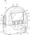
Fig. 2A illustrates a front view 200A of a pump assembly 230 (such as pump assembly 150) and a canister 220, according to some embodiments. As illustrated, the pump assembly 230 and the canister 220 are connected, thereby forming a device. The pump assembly 230 includes one or more indicators, such as a visual indicator 202 configured to indicate an alarm and a visual indicator 204 configured to indicate a status of the TNP system. Indicators 202 and 204 may be configured to notify a user (e.g., a patient or medical care provider) of various operational and/or fault conditions of the system, including notifying a user of a normal or proper operational state, a pump failure, a failure of power or power supplied to the pump, detection of a leak in the wound cover or flow path, an inhalation blockage, or any other similar or suitable condition, or combinations thereof. The pump assembly 230 can include additional indicators. The pump assembly may use a single indicator or multiple indicators. Any suitable indicator may be used, such as visual, audio, tactile, and the like. The indicator 202 may be configured to signal an alarm condition, such as a canister full, low power, conduit 140 broken, seal break in the wound seal 120, and the like. The indicator 202 may be configured to display a red flash to attract the attention of the user. The indicator 204 may be configured to signal the state of the TNP system, e.g., that therapy delivery is good, that a leak is detected, etc. The indicator 204 may be configured to display one or more different colors of light, such as green, yellow, and the like. For example, a green light may be emitted when the TNP system is operating normally and a yellow light may be emitted to indicate a warning.
The pump assembly 230 includes a display or screen 206 mounted in a recess 208 formed in the housing of the pump assembly. The display 206 may be a touch screen display. The display 206 may support playback of Audiovisual (AV) content, such as instructional video. As explained below, the display 206 may be configured to render a number of screens or Graphical User Interfaces (GUIs) for configuring, controlling and monitoring the operation of the TNP system. The pump assembly 230 includes a grip portion 210 formed in a housing of the pump assembly. The grip portion 210 may be configured to assist a user in gripping the pump assembly 230, for example during removal of the canister 220. For example, when the canister 220 is filled with fluid, the canister 220 may be replaced with another canister.
The pump assembly 230 includes one or more keys or buttons 212 configured to allow a user to operate and monitor the operation of the TNP system. As shown, buttons 212a, 212b, and 212c are included. The button 212a may be configured as a power button to turn the pump assembly 230 on/off. Button 212b may be configured as a run/pause button for delivering negative pressure therapy. For example, pressing button 212b may cause treatment to begin, and then pressing button 212b may cause treatment to pause or end. Button 212c may be configured to lock display 206 and/or button 212. For example, button 212c may be pressed so that the user does not inadvertently change the delivery of therapy. Button 212c may be pressed to unlock the controls. In other embodiments, additional buttons may be used, or one or more of the illustrated buttons 212a, 212b, or 212c may be omitted. A plurality of keys and/or key sequences may be used to operate the pump assembly 230.
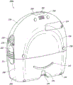
The pump assembly 230 includes one or more latch recesses 222 formed in the cover. In the illustrated embodiment, two latch recesses 222 can be formed on the side of the pump assembly 230. The latch recess 222 may be configured to allow the use of one or more tank latches 221 to attach and detach the tank 220. The pump assembly 230 includes an air outlet 224 for allowing air removed from the wound cavity 110 to escape. Air entering the pump assembly may pass through one or more suitable filters, such as an antimicrobial filter or the like. This may maintain the reusability of the pump assembly. The pump assembly 230 includes one or more strap mounts 226 for connecting the carrier strap to the pump assembly 230 or for attaching a bracket. In the illustrated embodiment, two band mounts 226 may be formed on the sides of the pump assembly 230. In some embodiments, various of these features are omitted, and/or various additional features are added to the pump assembly 230.
The canister 220 is configured to contain fluid (e.g., exudate) removed from the wound cavity 110. The canister 220 includes one or more latches 221 for attaching the canister to the pump assembly 230. In the illustrated embodiment, the canister 220 includes two latches 221 on the sides of the canister. The exterior of the can 220 may be formed of frosted plastic such that the can is substantially opaque and the contents of the can are substantially hidden from plan view. The canister 220 includes a grip portion 214 formed in the housing of the canister. The gripping portion 214 may be configured to allow a user to grip the pump assembly 220, for example during removal of the canister from the device 230. The canister 220 includes a substantially transparent window 216, which may also include a scale for volume. For example, the illustrated 300mL canister 220 includes graduations of 50mL, 100mL, 150mL, 200mL, 250mL, and 300 mL. Other embodiments of the canister may contain different volumes of fluid and may include different scales. For example, the canister may be an 800mL canister. The canister 220 includes a conduit channel 218 for connection to the conduit 140. In some embodiments, various of these features, such as the grip portion 214, are omitted, and/or various additional features are added to the canister 220. Any of the disclosed canisters may include or may omit a curing agent.
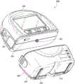
Fig. 2B illustrates a rear view 200B of the pump assembly 230 and the canister 220, according to some embodiments. The pump assembly 230 includes a speaker port 232 for generating sound. The pump assembly 230 includes a filter access door 234 for accessing and replacing one or more filters (e.g., antimicrobial filters). The pump assembly 230 includes a grip portion 236 formed in a housing of the pump assembly 230. The gripping portion 236 may be configured to allow a user to grip the pump assembly 230, for example during removal of the canister 220. The pump assembly 230 includes one or more covers 238 configured as threaded covers and/or feet or protectors for placing the pump assembly 230 on a surface. The cover 230 may be formed of rubber, silicone, or any other suitable material. The pump assembly 230 includes a power jack 239 for charging and recharging the internal battery of the pump assembly. Power jack 239 may be a Direct Current (DC) jack. In some embodiments, the pump assembly 230 may include a disposable power source, such as a battery, so that a power jack is not required.
The tank 220 includes one or more feet 244 for placing the tank on a surface. The feet 244 may be formed of rubber, silicone, or any other suitable material, and may be angled at a suitable angle so that the canister 220 remains stable when placed on a surface. The canister 220 includes a tube mounting relief (tube mount relief) 246 configured to allow one or more tubes to exit to the front of the device. The canister 220 includes a stand or support 248 for supporting the canister when it is placed on a surface. As explained below, the seat 248 may pivot between an open position and a closed position. In the closed position, the seat 248 may be latched to the canister 220. In some embodiments, the standoffs 248 may be made of an opaque material, such as plastic. In other embodiments, the standoffs 248 can be made of a transparent material. The seat 248 includes a gripping portion 242 formed therein. The grip portion 242 may be configured to allow a user to place the seat 248 in a closed position. The holder 248 includes an aperture 249 to allow a user to place the holder in an open position. The hole 249 may be sized to allow a user to pull out the holder using a finger.
Fig. 2C illustrates a view 200C of the pump assembly 230 separated from the canister 220, according to some embodiments. The pump assembly 230 includes a vacuum attachment, connector or inlet 252 through which a vacuum pump communicates negative pressure to the canister 220. The pump assembly draws fluid, such as gas, from the wound via the inlet 252. The pump assembly 230 includes a USB access door 256 configured to allow access to one or more USB ports. In some embodiments, the USB access gate is omitted and the USB port is accessed through gate 234. The pump assembly 230 may include additional access doors configured to allow access to additional serial, parallel, and/or hybrid data transfer interfaces, such as SD, Compact Disc (CD), DVD, FireWire, Thunderbolt, PCI Express, and the like. In other embodiments, one or more of these additional ports are accessed through the gate 234.
Additional description of the pump assembly 230 is disclosed in U.S. patent application No. 14/210,062, filed 3/13/2014, entitled "SYSTEMS AND METHODS FOR APPLYING pressure reducing pump heat, which is incorporated herein by reference in its entirety.
Electronic device and software
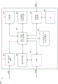
FIG. 3 illustrates an electrical component schematic 300 of a pump assembly, such as pump assembly 230, according to some embodiments. The electrical components may be operable to accept user input, provide output to a user, operate the pump assembly and TNP system, provide a network connection, and the like. The electrical components may be mounted on one or more Printed Circuit Boards (PCBs). As shown, the pump assembly may include multiple processors. It may be advantageous to utilize multiple processors in order to allocate or assign various tasks to different processors. The first processor may be responsible for user activity and the second processor may be responsible for controlling the pump. In this way, activities controlling the pump that may require a higher level of responsiveness (corresponding to a higher level of risk) may be offloaded to a dedicated processor and, thus, will not be interrupted by user interface tasks, which may take longer to complete due to interaction with the user.
The pump assembly may include a user interface processor or controller 310, such as a display 206, buttons 212, etc., configured to operate one or more components for accepting user input and providing output to a user. Inputs to and outputs from the pump assembly may be controlled by an input/output (I/O) module 320. For example, an I/O module may receive data from one or more ports, such as serial, parallel, mixed port, and the like. The processor 310 also receives data from and provides data to one or more expansion modules 360, such as one or more USB ports, SD ports, Compact Disc (CD) drives, DVD drives, FireWire ports, Thunderbolt ports, PCI Express ports, and the like, for example. The processor 310, along with other controllers or processors, stores data in one or more memory modules 350, which one or more memory modules 350 may be internal and/or external to the processor 310. Any suitable type of memory may be used, including volatile and/or non-volatile memory, such as RAM, ROM, magnetic memory, solid state memory, Magnetoresistive Random Access Memory (MRAM), and the like.
In some embodiments, the processor 310 may be a general purpose controller, such as a low power processor. In other embodiments, processor 310 may be a dedicated processor. The processor 310 can be configured as a "central" processor in the electronic architecture of the pump assembly, and the processor 310 can coordinate the activities of other processors, such as the pump control processor 370, the communication processor 330, and one or more additional processors 380 (e.g., a processor for controlling the display 206, a processor for controlling the buttons 212, etc.). The processor 310 may run a suitable operating system such as Linux, Windows CE, VxWorks, or the like.
The pump control processor 370 may be configured to control the operation of the negative pressure pump 390. The pump 390 may be a suitable pump such as a diaphragm pump, a peristaltic pump, a rotary vane pump, a scroll pump, a screw pump, a liquid ring pump, a diaphragm pump operated by a piezoelectric transducer, a voice coil pump, or the like. The pump may include one or more valves, such as inlet and outlet (or discharge) valves. The valve may be configured to open and close to enable the pump to draw fluid from the wound cavity 110. The pump control processor 370 can use data received from one or more pressure sensors to measure pressure in the fluid flow path, calculate the rate of fluid flow, and control the pump. The pump control processor 370 may control the pump motor such that a desired level of negative pressure is achieved in the wound cavity 110. The desired negative pressure level may be a pressure set or selected by the user. In various embodiments, the pump control processor 370 controls the pump (e.g., pump motor) using Pulse Width Modulation (PWM). The control signal for driving the pump may be a PWM signal of 0-100% duty cycle. The pump control processor 370 can perform flow rate calculations and detect various conditions in the flow path. The pump control processor 370 can communicate information to the processor 310. Pump control processor 370 can include internal memory and/or can utilize memory 350. The pump control processor 370 may be a low power processor. In some embodiments, the processor 310 is configured to control the pump 390 and the pump control processor 370 is not used.
The communication processor 330 may be configured to provide wired and/or wireless connectivity. The communication processor 330 may utilize one or more antennas 340 to transmit and receive data. The communication processor 330 may provide one or more of the following types of connections: global Positioning System (GPS) technology, cellular connections (e.g., 2G, 3G, LTE, 4G), WiFi connections, Internet connections, and the like. The connections may be used for various activities such as pump assembly location tracking, resource tracking, compliance monitoring, remote selection, uploading logs, alarms and other operational data, and adjustment of therapy settings, upgrading of software and/or firmware, etc. The communication processor 330 may provide dual GPS/cellular functionality. The cellular functionality may be, for example, 3G functionality. In such a case, if the GPS module is unable to establish a satellite connection due to various factors including atmospheric conditions, building or terrain interference, satellite geometry, etc., the 3G network connection may be used to determine the device location, for example, by using cell identification (cellidenitiation), triangulation, forward link timing (forward link timing), etc. The pump assembly can include a SIM card, and the SIM-based location information can be obtained.
The communication processor 330 may communicate information to the processor 310. The communication processor 330 may include internal memory and/or may utilize memory 350. The communication processor 330 may be a low power processor.
In some embodiments, the pump assembly can track and store various data, such as one or more of positioning data, treatment parameters, logs, device data, and the like. The pump assembly can track and record treatment and other operational data. The data may be stored, for example, in memory 350.
In some embodiments, using the connection provided by the communication processor 330, the device can upload any data stored, maintained, and/or tracked by the pump assembly. For example, the following information may be uploaded to a remote computer or server, namely: an activity log including therapy delivery information, such as therapy duration; an alarm log comprising an alarm type and an occurrence time; an error log including internal error information, transmission errors, and the like; treatment duration information, which may be calculated on an hourly basis, a daily basis, etc.; a total treatment time comprising a treatment duration from a first administration of one or more specific treatment regimens; lifelong treatment information; device information such as serial number, software version, battery level, etc.; device location information; patient information, etc. The device may also download various operational data such as treatment options and parameters, firmware and software patches, upgrades, and the like. The pump assembly can provide Internet browsing functionality using one or more browser programs, mail programs, application software (e.g., an app), and the like.
Controlling operation of a negative pressure source using synchronous sampling
Fig. 4 illustrates an electrical component schematic 400 of example components of a pump control processor, such as pump control processor 370, according to some embodiments. Although the components may be part of the pump control processor, in other embodiments, one or more components may be separate from the pump control processor. Components of the pump control processor can be used to sample a pressure signal provided by a pressure sensor of a pump assembly, such as pump assembly 230. The pressure sensor may sense pressure in or near an inlet of the pump assembly (or tank connection), such as inlet 252, to generate a pressure signal. The pressure sensor may measure the pressure in the canister (or in or near the dressing in a canister-less system). Additionally, although the components are described in the context of sampling pressure signals, in other embodiments, one or more other signals (e.g., motor voltage or current signals) may be similarly sampled using the components or sampled according to similar or identical timing.
In some embodiments, the opening (or closing) of the inlet valve results in a pressure transient in the fluid flow path. Opening (or closing) of the outlet valve may also result in the transmission of pressure transients. Measuring the pressure value when there is a transient and using the measured pressure value to control the pump can cause errors and mistakes. Therefore, it is advantageous to synchronize the pressure measurement (and pump control) with the duration when no pressure transients are present in the fluid flow path. In certain embodiments, pressure measurements of the pressure sensors are read (e.g., sampled) to be synchronized to "leak-through" pressure transients caused by operation of the pump (such as due to closing and/or opening of the at least one valve). This may be referred to as "synchronous" sampling. In contrast, reading pressure sensor measurements regardless of pump operation (e.g., opening and/or closing of a valve) may be referred to as "asynchronous" sampling. Whether the sampling is synchronized or unsynchronized, the measured pressure can be used to control the pump as explained below.
In some embodiments, synchronous sampling may be performed as follows. The pressure sensor may provide a pressure signal to a sampler module or sampler 412 of an analog-to-digital (a/D) processor 410. The sampler may be a sample and hold device. The sampler 412 may sample the pressure signal at a frequency, such as 500 Hz, 1 kHz, 2 kHz, or 10 kHz, such that the sampler 412 provides an analog value indicative of the pressure signal to the a/D converter 414 of the a/D processor 410 at the selected frequency. The sampler 412 may operate, for example, in a sampling mode or a DSP scan mode. The sampler may also perform anti-aliasing filtering (such as low-pass filtering at a suitable frequency) before the analog data is converted to digital form. The a/D converter 414 may convert the analog values received from the sampler 412 to digital values and store the digital values in an output buffer 416 of the a/D processor 410.
The filter 420 may access the digital values stored in the output buffer 416 and perform a filtering operation on the digital values. For example, the filter 420 may be an Infinite Impulse Response (IIR) filter (or Finite Impulse Response (FIR) filter) and perform a Low Pass Filtering (LPF) operation on the digital values to reduce higher frequency noise or smooth rapid changes in the sampled pressure signal due to pressure transients. Filter 420 may thus, for example, maintain a running average of digital values over one or more cycles or portions of cycles of opening and/or closing of a motor of a pump (such as pump 390) or one or more valves. In an exemplary embodiment, the filtering operation performed by filter 420 may be based on the following equation:

whereinrawSampleMay be a digital value removed from the output buffer 416,iirBitShiftit may be a constant weight factor and,averagermay be a variable for maintaining the intermediate filtering result, andfilteredSamplemay be the output value of filter 420. Filter 420 may store filtered digital values from the filtering operation in filter buffer 430. Filter 420 may, for example, operate at the same frequency as sampler 412, such that filter 420 provides the filtered values for each digital value to filter buffer 430 at the same frequency.
The storage processor 440 can access the filtered values stored in the filter buffer 430 and communicate the filtered values to a measurement buffer 450 (e.g., a ring buffer) for further processing by the pump control processor (e.g., for additional averaging to determine an estimated pressure near the inlet of the pump assembly, or to determine whether to trigger an alarm). In some embodiments, storage processor 440 may sample the filtered values stored in filter buffer 430 and transfer the sampled values to measurement buffer 450. Thus, storage processor 440 may not access all of the filtered values stored in filter buffer 430 in some cases, but may access a selected subset of the filtered values for further processing. In one example, the storage processor 440 may access the filtered values and communicate sampled values synchronized with the operation of the pump (such as after one or more valves of the pump are opened and/or closed). Advantageously, in certain embodiments, by sampling and transmitting filtered values synchronously with the operation of the pump, the storage processor 440 may avoid further processing of the filtered values corresponding to pressure transients generated in the flow path as each of the one or more valves of the pump opens and/or closes.
The filtered values corresponding to pressure transients may include more noise than other filtered values and are therefore undesirable for use in further processing by the pump control processor. In some embodiments, when the operating speed of the pump drops below a threshold (e.g., the rotational speed of the pump drops below 1Hz or 2 Hz) or the pump has been idling for at least a threshold period of time (e.g., 100ms or 500 ms), the storage processor 440 may sample the filtered values according to a timer (e.g., periodically, such as every 2 ms) and asynchronously from the operation of the pump and transmit the sampled values to the measurement buffer 450. That is, asynchronous sampling may be utilized when the pump is operated slowly (e.g., when the activity of the pump falls below an activity threshold). The storage processor 440 may further transfer the pump's system voltage and motor current (and/or any other measurements of the operation of the negative pressure device) from the filter buffer 430 to the measurement buffer 450.
The pump may include a tachometer or any other suitable device below (as described) for measuring rotation of the pump motor. For example, the pump may be a diaphragm pump operated by a DC motor and having inlet and outlet valves. One cycle of the pump may correspond to four revolutions of the motor (or any other suitable number of revolutions), and the tachometer may provide an indication for each revolution of the motor. The pressure sensor readings may be sampled by sampler 412 and converted to digital data by an a/D converter at a frequency or rate that exceeds the frequency rate of pump operation (e.g., as measured by a tachometer). The pressure is sampled (or oversampled) at a higher frequency than the opening and/or closing of one or both of the inlet and outlet valves and the speed of the pump motor (as measured by the tachometer). Oversampling allows for removal (e.g., by filter 420) of contributions due to pressure transients caused by opening and/or closing of the valve. The filtered pressure value may be removed from the filter buffer 430 in synchronization with an indication from the tachometer that the pump motor has been running (e.g., when the indication is reached or detected). This enables synchronous sampling.
In certain embodiments, the synchronized sampling may be performed by directly identifying the duration of the at least one pump valve opening and/or closing. For example, a pump (such as pump 390) may utilize one or more sensors that sense the opening and/or closing of the at least one valve. The information provided by the one or more sensors may be used to provide synchronous sampling. For example, the pressure may be sampled at some time after the opening and/or closing of the valve as indicated by the one or more sensors. This time may be determined based on one or more threshold intervals, such as, for example, 100ms (or any other suitable time) after the at least one valve is opened.
In some embodiments, a pump assembly (such as pump assembly 230) controls a vacuum pump according to a selected or programmed protocol to deliver negative pressure therapy to a wound. Control of the pump may be performed by the pump control processor 370 alone or in combination with the processor 310. For example, as explained above, the user may choose to operate continuously at a desired pressure (or negative pressure set point). The pump assembly may activate the vacuum pump, thereby reducing or lowering the pressure at the wound site (e.g., under the dressing) to reach the set point. As explained below, the decrease (draw down) may be performed by increasing the negative pressure at the wound until a set point is reached, the increase in negative pressure being limited by the maximum negative pressure change per unit time called compression. Wound reduction (wounddrawdown) may be defined as the period of time immediately after therapy has been initiated during which the wound has not reached the set point. As explained below, at the end of the time to reach the set point, the flow rate in the fluid flow path should be below the leak (or high flow) threshold and above the low vacuum threshold, otherwise an appropriate alarm will be activated.
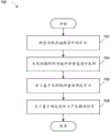
Fig. 5 illustrates a process 500 for providing negative pressure wound therapy, according to some embodiments. The process 500 may be performed by the pump control processor 370 alone or in combination with the processor 310. Process 500 may be performed periodically, for example, every 100 milliseconds (or 10 times per second) or at any other suitable frequency. Alternatively or additionally, process 500 may be performed continuously.
The process 500 may begin at block 502, and the process 500 may transition to block 502 when therapy is initiated or when the set point changes during the therapy being delivered. In block 502, the process 500 compares the wound pressure, which may be determined as explained below, to a set point. If the wound pressure is below the set point, the process 500 may transition to block 504. Conversely, if the wound pressure exceeds or equals the set point, the process 500 may transition to block 506.
In block 504 (pressure rise), the process 500 may increase the pump slant (ramp) set point by an amount that is dependent on the compression setting, as explained below. The vacuum pump will then attempt to reduce the wound pressure to reach the current value of the pump bias set point. For example, a suitable pump drive signal, such as a voltage or current signal, may be generated and provided to the pump motor in order to increase the speed of the pump motor to effect wound reduction. For efficiency purposes, the pump motor may be driven using PWM or any other suitable method. The process 500 may continue to increase the pump ramping setpoint until it reaches the user selected setpoint. When the wound pressure has nearly reached or reached the set point, the process 500 may transition to block 508. For example, the process 500 may transition to block 508 when the wound pressure is within an elevated threshold pressure of the set point, such as within 2mmHg of the set point or any other suitable value.
In block 506 (pressure drop), the process 500 may set the pump tilt setpoint to the user-selected setpoint. The process 500 may deactivate the pump so that the wound pressure is allowed to decay, for example due to one or more leaks in the fluid flow path, to reach or nearly reach the set point. At this point, process 500 may transition to block 508. For example, the process 500 may transition to block 508 when the wound pressure is within a reduced threshold pressure of the set point, such as within 5mmHg of the set point or within any other suitable value. In some cases, the falling threshold pressure may be the same as the rising threshold pressure.
In block 508 (steady state), the pump tilt setpoint may be set to a user-selected setpoint. The process 500 may control the vacuum pump to maintain a desired negative pressure at the wound site. One or more conditions, such as high vacuum, low vacuum, leaks, etc., may be detected in block 508, as explained below. If the user changes the setpoint to more negative or positive, or if delivery of therapy is suspended, the process 500 may transition to block 502.
In some embodiments, the pump assembly controls the vacuum pump to lower the wound by utilizing compression (e.g., as explained above in connection with block 504). The use of compression may be beneficial in avoiding rapid changes in wound pressure, which may minimize patient discomfort, reduce noise generated by operating the pump, maintain efficient delivery of negative pressure, maintain efficient use of power (e.g., battery power), and the like. The compression may be performed by the process 500, which in turn may be performed by the pump control processor 370 alone or in combination with the processor 310. The compression may correspond to a maximum desired increase in negative pressure per unit time at the wound site. The compression may be determined based on the negative pressure set point and the selected compression setting (e.g., low, medium, or high).
In some embodiments, the pump assembly monitors various parameters, such as pressure and flow rate in the fluid flow path, in order to control the pump in connection with the delivery of negative pressure wound therapy. Parameter monitoring and pump control may be performed by the pump control processor 370 alone or in combination with the processor 310. Monitoring flow rates may be used to ensure that therapy is properly delivered to the wound, to detect leaks, blockages, high and low vacuum, canister fill, and the like, among others.
The pump assembly may be configured to indirectly measure a flow rate in the fluid flow path. For example, the pump assembly may measure the speed (e.g., frequency) of the vacuum pump motor by using a tachometer. Alternatively or additionally, the pump assembly may use any suitable method to measure the activity level or duty cycle of the pump, such as by monitoring the voltage or current supplied to the pump (e.g., by sensing pump speed (e.g., by using a hall sensor), measuring the back emf generated by the pump motor, monitoring the duty cycle of the pump (e.g., the pump motor or actuator), and so forth. The tachometer readings may be averaged (e.g., by applying a low pass filter as explained above) to mitigate the effect of one or more erroneous readings. A number of most recent tachometer readings (e.g., over the past 2.5 seconds or any other suitable period of time) may be averaged to obtain a short tachometer average. A number of less recent tacho readings (e.g., over the past 30 seconds or any other suitable period of time) may be averaged to obtain a long tacho average. Short and long tachometer averages may be used for pump control. Additionally or alternatively, the pump assembly may measure the flow rate directly, for example by using a flow meter.
Additionally, one or more sensors may be used to determine and monitor the pressure in the flow path. In some embodiments, the pump assembly includes a pressure sensor in or near the inlet 252 (or tank connector) of the pump assembly 230. This pressure sensor may measure the pressure in the tank or in any other part of the fluid flow path (or in or near any other part of the fluid flow path of the adjunct or tankless system). An arrangement of one or more PRESSURE sensors is disclosed in U.S. patent application No. 14/210,062, filed 3/13/2014, entitled "SYSTEMS AND method for APPLYING PRESSURE REDUCED PRESSURE sensor, which is incorporated herein by reference in its entirety. The pump assembly may measure the pressure in the tank continuously, for example every millisecond or any other suitable duration. An appropriate number of the most recent pressure sensor readings may be averaged to mitigate the effect of one or more erroneous readings.
Wound pressure may be estimated using measured canister pressure and pump speed. The wound pressure may be different than the canister pressure due to the presence of one or more leaks in the flow path.
Based on the determined flow rate, canister pressure, and wound pressure values, the pump assembly monitors and detects various operating conditions and may control the pump. When the process is in block 508, one or more of these states may be detected by process 500. A blockage in the fluid flow path may be determined by comparing the flow rate reflected by the long tachometer average to a particular blockage threshold over a period of time or duration (e.g., 2 minutes or any other suitable duration). The occlusion threshold may be selected or determined based on a particular pressure set point. That is, to detect an occlusion, the pump assembly may utilize multiple occlusion thresholds corresponding to a particular pressure set point. As explained above, the flow rate may be determined indirectly by detecting and monitoring the pump speed. The long tachometer average may be compared to a jam threshold. Alternatively or additionally, the short tachometer average or any other suitable measurement of flow rate may be compared to the occlusion threshold.
During operation, the pump generates pressure pulses (e.g., pressure transients) that propagate through the fluid flow path. According to some embodiments, the pressure pulses that may be detected by the pressure sensor are illustrated by the pressure curve 602 of fig. 6. As illustrated in region 604, the pressure in the fluid flow path varies or oscillates about a particular pressure set point 608 during normal operation of the system. Region 606 illustrates a pressure pulse in the flow path that is present away from the blockage of the pump. For example, the canister (or dressing) becomes full, and/or the canister (or dressing) filter becomes clogged or clogged. As illustrated in region 606, the presence of the distal occlusion causes a reduced volume to be seen upstream of the canister (or dressing) and the amplitude of the pressure pulse to change (e.g., increase). The frequency of the pressure signal also changes (e.g., slows down or decreases). The observed change in one or more parameters of the pressure signal may be used to identify the type of distal occlusion present, for example to distinguish between canister (or dressing) fill and other types of occlusions in the fluid flow path. The change in the amplitude of the pressure signal may be measured using various techniques, such as by measuring peak-to-valley variations.
Fig. 7 illustrates a process 700 of providing negative pressure wound therapy according to some embodiments. The process 700 may be performed by the pump control processor 370 alone or in combination with the processor 310. Process 700 may be performed periodically or at any other suitable frequency. Alternatively or additionally, process 700 may be performed continuously. Advantageously, in certain embodiments, the process 700 may enable pressure measurements to be synchronized with the operation of the pump such that the effects of pressure measurements corresponding to pressure transients generated in the flow path due to the opening and/or closing of one or more valves of the pump may be reduced or eliminated.
At block 702, the process 700 may read a measurement of pressure in the fluid flow path. The measurements may have been received from a pressure sensor positioned to sense pressure at or near the inlet of a pump assembly, such as pump assembly 230, or at any other suitable portion of the fluid flow path. In one example, the measurement values may be obtained from the output buffer 416, which may be further filtered (such as by filter 420) before being stored in the filter buffer 430.
At block 704, the process 700 may sample the identified measurements in synchronization with the opening and/or closing of one or more valves (e.g., inlet or outlet valves) of a pump of the pump assembly, such as the pump 390. The measurement values may thus be sampled such that one or more of the identified measurement values are excluded from the sampled measurement values. For example, the measurements may be affected by pressure transients resulting from the periodic opening and/or closing of one or more valves of the pump, and the process 700 may sample the measurements so that one or more measurements that are more affected by the pressure transients than other measurements may be excluded from the sampled measurements. In some embodiments, the process 700 may determine the opening and/or closing of the one or more valves using signals from the pump or a sensor associated with the pump.
In one example, the process 700 may sample the measurement values at a sampling frequency corresponding to (e.g., proportional to) the opening and/or closing frequency of one or more valves of the pump. In another example, the process 700 may sample the measurement values such that the measurement values measured when one or more valves of the pump are at one position in an open and/or closed cycle are included in the sampled measurement values and the measurement values measured when one or more valves are at another position in an open and/or closed cycle are excluded from the sampled measurement values.
In yet another example, the process 700 may sample the measurement based at least on a frequency or ratio of signals received from a tachometer associated with the pump. The tachometer may be positioned to measure the speed of the pump's motor. Sampling of the measurements may include accessing and transmitting the pressure measurements for further processing, for example, in response to detecting one or either of a rising edge and a falling edge of the tachometer signal, such that the sampling is synchronized with the rotation of the motor (or operation of the pump).
At block 706, the process 700 may determine a pressure in the fluid flow path based at least on the sampled measurement. The pressure may, for example, be determined such that one or more measurements reflecting contributions due to pressure transients are excluded from the sampled measurements. The pressure may be more accurate than if the pressure were estimated based on both the sampled measurements and measurements excluded from the sampled measurements, because by not considering the measurements excluded from the sampled measurements in the determination of the pressure, the effects of pressure transients generated on each opening and/or closing of one or more valves of the pump may be reduced or eliminated.
At block 708, the process 700 may generate a drive signal to control operation of the pump based at least on the estimated pressure. For example, the drive signal may be a PWM signal, and the duty cycle of the drive signal may be varied to increase or decrease the speed of the pump based at least on the estimated pressure. In some embodiments, the duty cycle of the drive signal may be controlled using a proportional-integral-derivative (PID) calculation that is based at least on a difference between the pressure set point and the estimated pressure, as described with respect to process 800 of fig. 8.
Although process 700 is described as using sampling to reduce or eliminate the effects of pressure transients generated by one or more valves of a pump, in some embodiments one or more additional or other methods may be used to reduce or eliminate the effects of pressure transients generated by one or more valves of a pump. For example, the process 700 may weigh the measurement based at least on the synchronization of the measurement with the opening and/or closing of one or more valves of the pump. Measurements that are more affected by pressure transients resulting from the opening and/or closing of one or more valves of the pump than other measurements may be given less weight relative to the other measurements, such that measurements that are more affected by pressure transients are less affected than the other measurements in the determined estimated pressure.
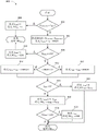
Fig. 8 illustrates a process for determining a duty cycle of a PWM control signal for a negative pressure source, in accordance with some embodiments. The process 800 may be performed by the pump control processor 370 alone or in combination with the processor 310. Process 800 may be performed periodically or at any other suitable frequency. Advantageously, in certain embodiments, the process 800 may enable the pump control processor 370 to determine an appropriate duty cycle for controlling a pump (such as the pump 390) such that the pump is ramped or controlled to a set point without: (1) significantly above the set point, or (2) control the pump to operate at a level different from the set point in a full tank condition.
The process 800 may be based on PID calculations and used as a control loop feedback mechanism. The control loop feedback mechanism may provide up to three controls based on an error value calculated based on the difference between the measured pressure and the set point pressure. The up to three controls may be controlled by a proportional control term (P)TERM) Integral control term (I)TERM) Or a differential control term (D)TERM) To be determined. In some embodiments, the output of the PID calculation (PID)OUT) May depend on PTERM、ITERMAnd DTERMThe sum of (1). In addition, ITERMCan be summed with the integral sum (I)SUM) In connection with this, the integrated sum may also depend on the accumulation of past errors. PIDOUTCan be provided withThe allowable range from 0 to 100 is determined such that 0 corresponds to a PWM control signal of 0% duty ratio and 100 corresponds to a PWM control signal of 100% duty ratio. As illustrated by process 800, in some embodiments, D is during process 800TERMMay be set to 0.
The process 800 may be similar in some respects to a standard PID calculation. However, the process 800 may include modifications to the standard PID calculations that improve the response of the PID calculations to various states in negative pressure wound therapy. For example, process 800 may include the following modifications:
● if the measured pressure exceeds the high vacuum alarm threshold, then ISUMCan be set to 0.
● if PTERMOver 100, then ISUMCan be set to 0 and PIDOUTMay be set to 100.
● if the difference between the pressure set point and the measured pressure is negative, then ISUMCan be set as ISUMThe sum is greater than the sum of the values of the differences.
● if ISUMLess than 0, then ISUMCan be set to 0, and PIDOUTCan be set to PTERMIt can avoid long PID restart delays after a pressure release period.
● if PTERMAnd ITERMIf the sum of (1) exceeds 100, PIDOUTCan be set to 100 and ISUMMay be reduced, such as in proportion to the sum exceeding 100.
Although process 800 may include all of the modifications referenced above, in some embodiments, process 800 may instead include one or more of the modifications without including one or more of the others, or may include different modifications.
At block 802, the process 800 may determine a measured pressure (P) in the flow pathMEASURED) Whether or not a high vacuum threshold (T) is exceededHIGH). The measured pressure may be a pressure measurement received from a pressure sensor positioned at or near an inlet of a pump assembly (such as pump assembly 230), and, in some instancesIn an embodiment, samples may have been taken from a set of measurements as discussed with respect to process 700. If the measured pressure exceeds the high vacuum threshold, at block 804, the process 800 may compare ISUMSet to 0, and set PIDOUTSet to 0 and the process 800 may proceed by returning the PIDOUTThe value of (2) ends.
If the measured pressure does not exceed the high vacuum threshold, at block 806, the process 800 may set ERROR to the difference between the pressure set point and the measured pressure, and P will be setTERMIs set to proportional gain (K)p) Multiplied by ERROR. The pressure set point may be set, for example, by a user of the pump assembly by setting a mode of operation or a desired pressure corresponding to the pressure set point. In some embodiments, the proportional gain may be set during test operation of the pump assembly or at the manufacture of the pump assembly using one or more control loop modulation methods. The proportional gain may be set, for example, to a value ranging from 0 to 1, ranging from 0.3 to 0.9, ranging from 0.5 to 0.7, or to 0.6.
At block 808, the process 800 may determine PTERMWhether it is equal to or exceeds 100. If P isTERMEqual to or above 100, at block 810, the process 800 may compare ISUMSet to 0, and set PIDOUTSet to 100 and process 800 may return the PIDOUTThe value of (2) ends. If P isTERMNot equal to or exceeding 100, at block 812, the process 800 may determine whether ERROR is less than 0. If ERROR is not less than 0, process 800 may couple I at block 814SUMIs set to be ISUMAnd 2 times ERROR. If ERROR is less than 0, process 800 may couple I at block 816SUMIs set to be ISUMAnd the sum of ERROR. At block 818, the process 800 may determine ISUMWhether less than 0. If ISUMLess than 0, at block 820, the process 800 may divide ISUMSet to 0, and set PIDOUTIs set to PTERMAnd the process 800 may return the PIDOUTThe value of (2) ends.
If ISUMNot less than 0, at block 822, process 800 may couple ITERMIs set to integral gain (K)I) Multiplied by ISUMAnd will PIDOUTIs set to PTERMAnd ITERMAnd (4) summing. In some embodiments, the proportional gain may be set to a value ranging from 0 to 1, ranging from 0.0001 to 0.0003, or to 0.0002. At block 824, the process 800 may determine a PIDOUTWhether it exceeds 100. If PIDOUTNot more than 100, then the process 800 may proceed by returning the PIDOUTThe value of (2) ends. If PIDOUTBeyond 100, at block 826, process 800 may scale ISUM(e.g., by an amount that depends on the PIDOUTBy more than 100 or with PIDOUTIn proportion to an amount exceeding 100), and the PID is adjustedOUTSet to 100 and process 800 may return the PIDOUTThe value of (2) ends.
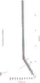
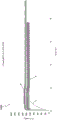
Figures 9A-9B and 10A-10B illustrate plots of operating pressures for a simulated reduced pressure wound therapy system according to some embodiments. Fig. 9A-9B depict exemplary plots of operating pressures for a simulation system that does not implement at least some of the teachings provided by the present disclosure, such as the teachings described with respect to process 700 (e.g., using sampled pressure values) and process 800 (e.g., a PID-calculation-based control process). 10A-10B depict exemplary plots of operating pressures for a simulation system that does not use at least some of the teachings provided by the present disclosure, such as the teachings described with respect to processes 700 and 800.
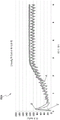
FIG. 9A shows an exemplary plot 900A for control and reduction operation of a pump to attempt to reduce pressure at a wound to 120mmHg without using synchronous sampling. Lines A, B and C of plot 900A illustrate simulated operating pressures for a system having a full tank, a nearly full tank, and an empty tank, respectively. At the time of 0 seconds, the pump starts operating to reduce the pressure. At a time of about 3 seconds, the pump has completed the lowering operation and entered steady state operation. As can be seen from lines a and B of plot 900A, the pressure in the simulated system indicates a transient between 0 seconds and 0.5 seconds (which is not removed because synchronous sampling is not used) or the presence of a significant pressure pulse. Operating the pump without removing or mitigating the contribution due to such pressure pulses or transients at pump start-up may be undesirable in some situations and may be uncomfortable or painful to the patient, for example. Additionally, as can be seen from line a of plot 900A, a canister full condition may also result in a pump reduction of 100mmHg instead of 120mmHg as desired. Thus, the pump may also not work well when the tank is full (or even when the tank is empty or relatively empty).
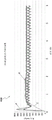
Fig. 9B shows an exemplary plot 900B for controlling a pump in the presence of a pressure transient of 120mmHg without the use of synchronous sampling. Lines A, B and C of plot 900B illustrate simulated operating pressures for a system having a full tank, a nearly full tank, and an empty tank, respectively. At the 0 second time, the pump begins to operate to reduce the pressure at the wound site. The time between 0 and 1 second illustrates the occurrence of a pressure transient (which is not removed since synchronous sampling is not used). At a time of about 1 second, the pressure transient has ceased or ended. As can be seen from lines a and B of plot 900B, the pressure in the simulated system may show a significant pressure overshoot between 0 seconds and 0.3 seconds due to the pressure transient. Operating the pump without removing or mitigating the contribution due to such pressure overshoot may be undesirable in some situations and may be uncomfortable or painful to the patient, for example. Additionally, as can be seen from line a of plot 900B, a canister full condition may cause the pump to adjust the pressure by 100mmHg instead of 120mmHg as desired. Thus, the pump may not work well when the tank is full (or even when the tank is empty or relatively empty).
Fig. 10A shows an exemplary plot 1000A for control and derate operation of the pump to attempt to derate the pressure by 120mmHg, and fig. 10B shows an exemplary plot 1000B for control and transient operation of the pump with a pressure transient of 120 mmHg. In both plots 1000A and 1000B, synchronous sampling is utilized. In comparison to fig. 9A-9B, fig. 10A-10B show a smooth decrease in pressure, minimal overshoot after a transient event, relatively fast adjustment to reach the pressure set point, and effective adjustment of pressure independent of the remaining capacity of the tank, as can be seen from lines A, B and C of plots 1000A and 1000B. Additionally, as can be seen from line a of plots 1000A and 1000B, the pressure may be adjusted closer to the pressure set point than is achievable in the system depicted by plots 900A and 900B. Thus, the use of synchronous sampling for controlling the pump results in, for example, increased efficiency, reduced noise and vibration due to operation of the pump, reduced use of energy, and better comfort for the patient.
Other variants
Any values provided herein for thresholds, limits, durations, and the like, are not intended to be absolute, and thus may be approximate. Further, any thresholds, limits, durations, etc. provided herein may be fixed or changed automatically or by a user. Further, as used herein, relative terms such as over, greater than, less than, and the like with respect to a reference value are also intended to include being equal to the reference value. For example, exceeding the reference value as positive may include being equal to or greater than the reference value. Further, as used herein, relative terms such as above, greater than, less than, and the like with respect to a reference value are also intended to encompass an inverse of the disclosed relationship, such as below, less than, greater than, and the like with respect to the reference value.
Features, materials, characteristics or groups described in connection with a particular aspect, embodiment or example are to be understood as applicable to any other aspect, embodiment or example described herein unless incompatible therewith. All of the features disclosed in this specification (including any accompanying claims, abstract and drawings), and/or all of the steps of any method or process so disclosed, may be combined in any combination, except combinations where at least some of such features and/or steps are mutually exclusive. The protection is not restricted to the details of any of the foregoing embodiments. Any novel one, or any novel combination, of the features disclosed in this specification (including any accompanying claims, abstract and drawings), or any novel one, or any novel combination, of the steps of any method or process so disclosed, is/are protected.
While certain embodiments have been described, these embodiments have been presented by way of example only, and are not intended to limit the scope of protection. Indeed, the novel methods and systems described herein may be embodied in a variety of other forms. Furthermore, various omissions, substitutions and changes in the form of the methods and systems described herein may be made. Those of skill in the art will understand that in some embodiments, the actual steps taken in the processes shown and/or disclosed may differ from those shown in the figures. According to embodiments, some of the steps described above may be removed, and other steps may be added. For example, the actual steps and/or order of steps taken in the disclosed processes may differ from those shown in the figures. According to embodiments, some of the steps described above may be eliminated, and other steps may be added. For example, the various components shown in the figures may be implemented as software and/or firmware on a processor, controller, ASIC, FPGA, and/or dedicated hardware. Hardware components such as processors, ASICs, FPGAs, and the like may include logic circuitry. Furthermore, the features and attributes of the specific embodiments disclosed above can be combined in different ways to form additional embodiments, all of which fall within the scope of the present disclosure.
While the present disclosure includes certain embodiments, examples, and applications, it will be understood by those skilled in the art that the present disclosure extends beyond the specifically disclosed embodiments to other alternative embodiments and/or uses and obvious modifications and equivalents thereof, including embodiments that do not provide all of the features and advantages set forth herein. Accordingly, the scope of the present disclosure is not intended to be limited by the specific disclosure of the preferred embodiments herein, and may be defined by the claims presented herein or hereafter.
Claims (20)
1. An apparatus for applying negative pressure therapy to a wound, comprising:
a housing comprising a negative pressure source configured to be in fluid communication with a wound dressing, the negative pressure source comprising at least one valve;
a pressure sensor configured to measure pressure in a fluid flow path configured to fluidly connect the wound dressing and the negative pressure source; and
a controller configured to operate the negative pressure source using a drive signal, the controller further configured to:
determining a pressure measurement value based on the pressure measured by the pressure sensor, wherein the determination is performed in synchronization with the operation of the negative pressure source, and
generating a drive signal based at least on the determined pressure;
wherein the pressure measured by the pressure sensor comprises one or more components of the pressure transient due to the opening and/or closing by the at least one valve and the one or more components are substantially excluded from the determination of the pressure measurement.
2. The apparatus of claim 1, wherein the controller is configured to determine the pressure in synchronization with the opening and/or closing of the at least one valve.
3. The apparatus of claim 1, wherein the pressure transient is generated periodically by the at least one valve.
4. The apparatus of claim 2, wherein the controller is configured to determine the pressure measurement synchronously with the opening and/or closing of the at least one valve by sampling the measurement at a frequency that exceeds the at least one valve opening and/or closing frequency.
5. The apparatus of claim 4, wherein the sampling frequency is proportional to a frequency at which the at least one valve opens and/or closes.
6. The apparatus of claim 1, wherein the controller is configured to determine the pressure measurement synchronously with operation of the negative pressure source based on one or more measurements obtained while the at least one valve is in the first position and not based on one or more measurements obtained while the at least one valve is in the second position.
7. The apparatus of claim 1, wherein the negative pressure source comprises a vacuum pump having a motor, and the controller is configured to determine the pressure measurement synchronously with operation of the negative pressure source based at least on a speed of the motor.
8. The apparatus of claim 7, further comprising a tachometer configured to measure a speed of the motor and generate a signal indicative of the measured speed of the motor, and wherein the controller is configured to determine the pressure measurement based on the signal received from the tachometer in synchronization with operation of the negative pressure source.
9. The apparatus of claim 8, wherein the controller is configured to determine the pressure measurement in synchronization with operation of the negative pressure source in response to a rising edge of the speed signal and in response to a falling edge of the speed signal.
10. The apparatus of claim 1, wherein the controller is configured to determine the pressure measurement value synchronously with operation of the negative pressure source based on a signal received from the negative pressure source.
11. The apparatus of claim 1, wherein the at least one valve comprises an inlet valve and an outlet valve.
12. The apparatus of claim 1, wherein the controller is configured to determine the pressure measurements synchronously with operation of the negative pressure source by applying a low pass filter to a plurality of measurements obtained from the pressure sensor.
13. The apparatus of claim 1, wherein the controller is further configured to determine the pressure measurement value asynchronously to operation of the negative pressure source in response to determining that activity of the negative pressure source falls below an activity threshold.
14. The apparatus of claim 1, wherein the controller is configured to control the negative pressure source using Pulse Width Modulation (PWM) and to generate the drive signal using a proportional-integral-derivative (PID) calculation based at least on a difference between the pressure set point and the determined pressure.
15. The apparatus of claim 14, wherein the controller is configured to generate the drive signal having a duty cycle of 0% in response to determining that the determined pressure exceeds a first threshold.
16. The apparatus of claim 14, wherein the controller is configured to generate the drive signal having a duty cycle of 100% in response to determining that the proportional term calculated by the PID exceeds a first threshold.
17. The apparatus of claim 14, wherein the controller is configured to generate the drive signal having a duty cycle of 100% in response to determining that a sum of a proportional term calculated by the PID and an integral term calculated by the PID exceeds a first threshold.
18. The apparatus of claim 14, wherein the controller is configured to set an integral term of the PID calculation to 0 and set an accumulated error of the PID calculation to 0 in response to determining that the accumulated error is less than 0.
19. The apparatus of claim 14, wherein the controller is configured to set a cumulative error of the PID calculation to be greater than a sum of the cumulative error and the difference in response to determining that the difference is negative.
20. The apparatus of claim 1, wherein the controller is configured to determine the pressure measurement by sampling a pressure measured by the pressure sensor.
Applications Claiming Priority (3)
| Application Number | Priority Date | Filing Date | Title |
|---|---|---|---|
| US201462097765P | 2014-12-30 | 2014-12-30 | |
| US62/097,765 | 2014-12-30 | ||
| PCT/US2015/061165 WO2016109041A1 (en) | 2014-12-30 | 2015-11-17 | Systems and methods for applying reduced pressure therapy |
Publications (2)
| Publication Number | Publication Date |
|---|---|
| CN107106743A CN107106743A (en) | 2017-08-29 |
| CN107106743B true CN107106743B (en) | 2020-06-05 |
Family
ID=54780463
Family Applications (1)
| Application Number | Title | Priority Date | Filing Date |
|---|---|---|---|
| CN201580072035.9A Active CN107106743B (en) | 2014-12-30 | 2015-11-17 | Systems and methods for applying reduced pressure therapy |
Country Status (8)
| Country | Link |
|---|---|
| US (2) | US10556045B2 (en) |
| EP (1) | EP3240587B1 (en) |
| JP (1) | JP6698091B2 (en) |
| CN (1) | CN107106743B (en) |
| AU (1) | AU2015374632B2 (en) |
| CA (1) | CA2972691C (en) |
| SG (1) | SG11201704636RA (en) |
| WO (1) | WO2016109041A1 (en) |
Families Citing this family (29)
| Publication number | Priority date | Publication date | Assignee | Title |
|---|---|---|---|---|
| JP6991067B2 (en) | 2014-12-22 | 2022-01-12 | スミス アンド ネフュー ピーエルシー | Negative pressure closure therapy equipment and methods |
| US10556045B2 (en) | 2014-12-30 | 2020-02-11 | Smith & Nephew, Inc. | Synchronous pressure sampling and supply of negative pressure in negative pressure wound therapy |
| EP3297697B1 (en) | 2015-05-18 | 2022-05-11 | Smith & Nephew plc | Negative pressure wound therapy apparatus |
| CA2995469C (en) | 2015-08-13 | 2023-10-03 | Smith & Nephew, Inc. | Systems and methods for applying reduced pressure therapy |
| US11771820B2 (en) | 2016-03-04 | 2023-10-03 | Smith & Nephew Plc | Negative pressure wound therapy apparatus for post breast surgery wounds |
| CA3035134A1 (en) * | 2016-08-31 | 2018-03-08 | Smith & Nephew Plc | Systems and methods for controlling operation of a reduced pressure therapy system to detect leaks |
| US11369730B2 (en) | 2016-09-29 | 2022-06-28 | Smith & Nephew, Inc. | Construction and protection of components in negative pressure wound therapy systems |
| WO2018150263A1 (en) | 2017-02-15 | 2018-08-23 | Smith & Nephew Pte. Limited | Negative pressure wound therapy apparatuses and methods for using the same |
| JP2018134353A (en) * | 2017-02-24 | 2018-08-30 | 三鷹光器株式会社 | Drape exhaust structure of surgical microscope apparatus |
| JP2020508767A (en) | 2017-02-28 | 2020-03-26 | ティージェイ スミス アンド ネフュー リミテッド | Multiple dressings negative pressure wound therapy system |
| JP7063912B2 (en) | 2017-03-07 | 2022-05-09 | スミス アンド ネフュー インコーポレイテッド | Decompression therapy system and method including antenna |
| WO2018170151A1 (en) * | 2017-03-15 | 2018-09-20 | Smith & Nephew, Inc. | Pressure control in negative pressure wound therapy systems |
| EP3612242A1 (en) | 2017-04-19 | 2020-02-26 | Smith & Nephew, Inc | Negative pressure wound therapy canisters |
| WO2019063467A1 (en) | 2017-09-29 | 2019-04-04 | T.J.Smith And Nephew,Limited | Negative pressure wound therapy apparatus with removable panels |
| EP3482782A1 (en) * | 2017-11-14 | 2019-05-15 | Medela Holding AG | Medical suction pump |
| GB201813282D0 (en) | 2018-08-15 | 2018-09-26 | Smith & Nephew | System for medical device activation and opertion |
| US10624794B2 (en) | 2018-02-12 | 2020-04-21 | Healyx Labs, Inc. | Negative pressure wound therapy systems, devices, and methods |
| AU2019232735A1 (en) * | 2018-03-06 | 2020-10-22 | Centese, Inc. | Devices and methods for managing chest drainage |
| GB201804347D0 (en) | 2018-03-19 | 2018-05-02 | Smith & Nephew Inc | Securing control of settings of negative pressure wound therapy apparatuses and methods for using the same |
| GB201806988D0 (en) | 2018-04-30 | 2018-06-13 | Quintanar Felix Clarence | Power source charging for negative pressure wound therapy apparatus |
| USD888225S1 (en) | 2018-04-30 | 2020-06-23 | Smith & Nephew Asia Pacific Pte. Limited | Pump and canister assembly for negative pressure wound therapy |
| US11559619B2 (en) * | 2018-04-30 | 2023-01-24 | Smith & Nephew Asia Pacific Pte. Limited | Systems and methods for controlling dual mode negative pressure wound therapy apparatus |
| GB201808438D0 (en) * | 2018-05-23 | 2018-07-11 | Smith & Nephew | Systems and methods for determining blockages in a negative pressure wound therapy system |
| CN112654387B (en) * | 2018-07-02 | 2023-08-15 | 米奈特朗尼克斯神经有限公司 | Systems, catheters, and methods for treatment along the central nervous system |
| GB201814158D0 (en) | 2018-08-31 | 2018-10-17 | Smith & Nephew | Blockage and leak detection in multiple dressing reduced pressure wound therapy systems |
| CA3115799A1 (en) * | 2018-11-26 | 2020-06-04 | Alcon Inc. | Methods and systems for controlling aspiration flow rate |
| GB201914283D0 (en) * | 2019-10-03 | 2019-11-20 | Smith & Nephew | Apparatuses and methods for negative pressure wound therapy |
| GB202002338D0 (en) * | 2020-02-20 | 2020-04-08 | Convatec Ltd | A method and control system for a wound therapy apparatus |
| SE2051209A1 (en) * | 2020-10-19 | 2022-04-20 | Thoragen Ab | Improved body drainage apparatus |
Citations (1)
| Publication number | Priority date | Publication date | Assignee | Title |
|---|---|---|---|---|
| CN1571682A (en) * | 2001-08-24 | 2005-01-26 | Kci特许公司 | Vacuum assisted tissue treatment system |
Family Cites Families (157)
| Publication number | Priority date | Publication date | Assignee | Title |
|---|---|---|---|---|
| US6241704B1 (en) | 1901-11-22 | 2001-06-05 | Sims Deltec, Inc. | Drug pump systems and methods |
| GB2235877A (en) | 1989-09-18 | 1991-03-20 | Antonio Talluri | Closed wound suction apparatus |
| US5419768A (en) | 1991-03-07 | 1995-05-30 | Aeros Instruments, Inc. | Electrical medical vacuum regulator |
| DE4301524A1 (en) | 1993-01-21 | 1994-07-28 | Jostra Medizintechnik | Medical unit or device for operating theaters, in particular heart-lung machine |
| US5449347A (en) | 1994-07-05 | 1995-09-12 | The United States Of America As Represented By The Secretary Of The Air Force | Patient transport, plural power source suction apparatus |
| GB9523253D0 (en) | 1995-11-14 | 1996-01-17 | Mediscus Prod Ltd | Portable wound treatment apparatus |
| US5813972A (en) | 1996-09-30 | 1998-09-29 | Minnesota Mining And Manufacturing Company | Medical perfusion system with data communications network |
| AU9787498A (en) | 1997-10-02 | 1999-04-27 | Micromed Technology, Inc. | Implantable pump system |
| DE69842053D1 (en) | 1997-12-27 | 2011-01-27 | Jms Co Ltd | BLOOD CIRCULATION ASSISTANCE DEVICE WITH A CONTINUOUS BLOOD FLOW PUMP |
| US7647237B2 (en) | 1998-04-29 | 2010-01-12 | Minimed, Inc. | Communication station and software for interfacing with an infusion pump, analyte monitor, analyte meter, or the like |
| GB9822341D0 (en) | 1998-10-13 | 1998-12-09 | Kci Medical Ltd | Negative pressure therapy using wall suction |
| US6540672B1 (en) | 1998-12-09 | 2003-04-01 | Novo Nordisk A/S | Medical system and a method of controlling the system for use by a patient for medical self treatment |
| SE9902971L (en) | 1999-08-23 | 2001-02-24 | Two Inventors Hb | Method and apparatus for treating and adding an additive in the collection of a liquid |
| US6241739B1 (en) | 1999-11-12 | 2001-06-05 | Altair Instruments, Inc. | Microdermabrasion device and method of treating the skin surface |
| US6824533B2 (en) | 2000-11-29 | 2004-11-30 | Hill-Rom Services, Inc. | Wound treatment apparatus |
| CA2390131C (en) | 1999-11-29 | 2009-06-23 | Hill-Rom Services, Inc. | Wound treatment apparatus |
| US6764462B2 (en) | 2000-11-29 | 2004-07-20 | Hill-Rom Services Inc. | Wound treatment apparatus |
| US20010049609A1 (en) | 2000-03-09 | 2001-12-06 | Michael Girouard | System for assisting wound treatment management |
| US6976977B2 (en) | 2000-12-06 | 2005-12-20 | Sherwood Services Ag | Vacuum setting and indication system for a drainage device |
| ATE465707T1 (en) | 2001-07-12 | 2010-05-15 | Kci Medical Resources | CONTROL OF VACUUM CHANGE RATE |
| US6955664B2 (en) | 2001-07-17 | 2005-10-18 | D'antonio Consultants International, Inc. | Suction regulator and fluid drainage system |
| US7723560B2 (en) | 2001-12-26 | 2010-05-25 | Lockwood Jeffrey S | Wound vacuum therapy dressing kit |
| EP1565219B2 (en) | 2002-05-31 | 2021-11-03 | KCI Licensing, Inc. | Wound treatment apparatus |
| AU2003251127A1 (en) | 2002-06-14 | 2003-12-31 | Margaret Pamela Richardson | Improvements in and relating to control of liquid flow into or out of a human or animal body |
| EP1389476A1 (en) | 2002-08-14 | 2004-02-18 | Precimedix S.A. | Programming device for a pump for injecting medicaments |
| US7846141B2 (en) | 2002-09-03 | 2010-12-07 | Bluesky Medical Group Incorporated | Reduced pressure treatment system |
| US7815616B2 (en) | 2002-09-16 | 2010-10-19 | Boehringer Technologies, L.P. | Device for treating a wound |
| US7998107B2 (en) | 2002-09-24 | 2011-08-16 | Kensey Nash Corporation | Interventional procedure drive and control system |
| FR2845888B1 (en) | 2002-10-16 | 2005-07-15 | Promepla Sam | DEVICE FOR SINGLE USE OF INFORMATION TRANSMISSIONS, USED IN MEDICAL AND SURGICAL FIELDS |
| GB0224986D0 (en) | 2002-10-28 | 2002-12-04 | Smith & Nephew | Apparatus |
| US7300418B2 (en) | 2003-03-10 | 2007-11-27 | Siemens Medical Solutions Health Services Corporation | Healthcare system supporting multiple network connected fluid administration pumps |
| US8353857B2 (en) | 2003-06-23 | 2013-01-15 | Codman & Shurtleff, Inc. | Implantable medical device having pressure sensors for diagnosing the performance of an implanted medical device |
| US8137305B2 (en) | 2007-01-22 | 2012-03-20 | Kelly Patricia A | Programmable electric breast pump |
| US7361184B2 (en) | 2003-09-08 | 2008-04-22 | Joshi Ashok V | Device and method for wound therapy |
| US20050065471A1 (en) | 2003-09-23 | 2005-03-24 | Charles Kuntz | Continuous safe suction device |
| US8062272B2 (en) | 2004-05-21 | 2011-11-22 | Bluesky Medical Group Incorporated | Flexible reduced pressure treatment appliance |
| US7776028B2 (en) | 2004-04-05 | 2010-08-17 | Bluesky Medical Group Incorporated | Adjustable overlay reduced pressure wound treatment system |
| US7708724B2 (en) | 2004-04-05 | 2010-05-04 | Blue Sky Medical Group Incorporated | Reduced pressure wound cupping treatment system |
| US7753894B2 (en) | 2004-04-27 | 2010-07-13 | Smith & Nephew Plc | Wound cleansing apparatus with stress |
| GB0409446D0 (en) | 2004-04-28 | 2004-06-02 | Smith & Nephew | Apparatus |
| CA2574927A1 (en) | 2004-07-26 | 2006-02-09 | Kci Licensing, Inc. | Method for coating substrate with antimicrobial agent and product formed thereby |
| US7612247B2 (en) | 2004-09-29 | 2009-11-03 | Oyaski Michael F | Wound alternative treatment system |
| DE102005001868A1 (en) | 2005-01-14 | 2006-07-20 | Inmeditec Medizintechnik Gmbh | Medical pump system operating method, e.g. for bedsore prevention system, uses controller to record data , and transfers data to data centre for storage and statistical analysis via two-way interface |
| CN101185079A (en) | 2005-04-11 | 2008-05-21 | 霍夫曼-拉罗奇有限公司 | Web-enabled portable medical device |
| US7945452B2 (en) | 2005-04-11 | 2011-05-17 | Hospira, Inc. | User interface improvements for medical devices |
| DE102005025516A1 (en) | 2005-06-03 | 2006-12-07 | Fresenius Medical Care Deutschland Gmbh | Medical treatment system with a device for providing patient-related data |
| US20070005030A1 (en) | 2005-06-21 | 2007-01-04 | Hopkins Mark A | Aspiration control via flow or impedance |
| US7438705B2 (en) | 2005-07-14 | 2008-10-21 | Boehringer Technologies, L.P. | System for treating a wound with suction and method detecting loss of suction |
| US20110077605A1 (en) * | 2005-07-14 | 2011-03-31 | Boehringer Technologies, L.P. | Pump system for negative pressure wound therapy |
| US7857806B2 (en) | 2005-07-14 | 2010-12-28 | Boehringer Technologies, L.P. | Pump system for negative pressure wound therapy |
| US7503910B2 (en) | 2006-02-01 | 2009-03-17 | Carmeli Adahan | Suctioning system, method and kit |
| US7837673B2 (en) | 2005-08-08 | 2010-11-23 | Innovative Therapies, Inc. | Wound irrigation device |
| US7608066B2 (en) | 2005-08-08 | 2009-10-27 | Innovative Therapies, Inc. | Wound irrigation device pressure monitoring and control system |
| WO2007062024A1 (en) | 2005-11-21 | 2007-05-31 | Joshua David Smith | Wound care system |
| CA2641569C (en) | 2006-02-09 | 2015-10-06 | Deka Products Limited Partnership | Fluid delivery systems and methods |
| US8852149B2 (en) | 2006-04-06 | 2014-10-07 | Bluesky Medical Group, Inc. | Instructional medical treatment system |
| US7933817B2 (en) | 2006-06-14 | 2011-04-26 | Boehringer Technologies, L.P. | Billing method for pump usage |
| WO2008021306A2 (en) | 2006-08-15 | 2008-02-21 | Bio-Innovative Operations, Inc. | Computer adjusted pressure wound care devices, systems & methods |
| US8025634B1 (en) | 2006-09-18 | 2011-09-27 | Baxter International Inc. | Method and system for controlled infusion of therapeutic substances |
| US8061360B2 (en) | 2006-09-19 | 2011-11-22 | Kci Licensing, Inc. | System and method for locating fluid leaks at a drape of a reduced pressure delivery system |
| US7876546B2 (en) | 2006-09-19 | 2011-01-25 | Kci Licensing Inc. | Component module for a reduced pressure treatment system |
| US8366690B2 (en) | 2006-09-19 | 2013-02-05 | Kci Licensing, Inc. | System and method for determining a fill status of a canister of fluid in a reduced pressure treatment system |
| US7862339B2 (en) | 2006-09-21 | 2011-01-04 | Tyco Healthcare Group Lp | Negative wound pressure therapy test system |
| MX2009003284A (en) | 2006-09-26 | 2010-02-09 | Boehringer Technologies Lp | Pump system for negative pressure wound therapy. |
| DE602007004546D1 (en) | 2006-09-28 | 2010-03-18 | Tyco Healthcare | Portable wound therapy system |
| EP2438935B1 (en) | 2006-10-13 | 2014-01-15 | BlueSky Medical Group Incorporated | Pressure control of a medical vacuum pump |
| CA2666797C (en) * | 2006-10-17 | 2017-06-20 | Bluesky Medical Group Inc. | Auxiliary powered negative pressure wound therapy apparatuses and methods |
| US8377016B2 (en) | 2007-01-10 | 2013-02-19 | Wake Forest University Health Sciences | Apparatus and method for wound treatment employing periodic sub-atmospheric pressure |
| EP2109472B2 (en) | 2007-02-09 | 2022-05-11 | KCI Licensing, Inc. | System for managing reduced pressure at a tissue site |
| US7927319B2 (en) | 2007-02-20 | 2011-04-19 | Kci Licensing, Inc. | System and method for distinguishing leaks from a disengaged canister condition in a reduced pressure treatment system |
| GB0715211D0 (en) | 2007-08-06 | 2007-09-12 | Smith & Nephew | Apparatus |
| US9408954B2 (en) | 2007-07-02 | 2016-08-09 | Smith & Nephew Plc | Systems and methods for controlling operation of negative pressure wound therapy apparatus |
| GB0712739D0 (en) | 2007-07-02 | 2007-08-08 | Smith & Nephew | Apparatus |
| GB0712760D0 (en) | 2007-07-02 | 2007-08-08 | Smith & Nephew | Status indication |
| GB0715276D0 (en) | 2007-08-06 | 2007-09-12 | Smith & Nephew | Pump control |
| GB0712757D0 (en) * | 2007-07-02 | 2007-08-08 | Smith & Nephew | Pressure control |
| GB0715264D0 (en) | 2007-08-06 | 2007-09-12 | Smith & Nephew | Determining flow rate |
| GB0715259D0 (en) | 2007-08-06 | 2007-09-12 | Smith & Nephew | Canister status determination |
| GB0712759D0 (en) | 2007-07-02 | 2007-08-08 | Smith & Nephew | Measuring pressure |
| WO2009021047A2 (en) | 2007-08-06 | 2009-02-12 | Ohio Medical Corporation | Wound treatment system and suction regulator for use therewith |
| CN101821743A (en) | 2007-08-10 | 2010-09-01 | 施曼信医疗Asd公司 | Be used to control the system of Medical Devices |
| WO2009047524A2 (en) | 2007-10-10 | 2009-04-16 | Talley Group Limited | Medical apparatus for use in negative pressure wound therapy |
| US20090105670A1 (en) | 2007-10-23 | 2009-04-23 | Boehringer Technologies, L.P. | Thin film wound cover, suction assisted wound treatment system using the same, method of using the thin film wound cover and method of making the same |
| CA2705896C (en) | 2007-11-21 | 2019-01-08 | Smith & Nephew Plc | Wound dressing |
| GB0723876D0 (en) | 2007-12-06 | 2008-01-16 | Smith & Nephew | Apparatus and method for topical negative pressure therapy |
| GB0723855D0 (en) | 2007-12-06 | 2008-01-16 | Smith & Nephew | Apparatus and method for wound volume measurement |
| ATE546174T1 (en) | 2008-01-08 | 2012-03-15 | Bluesky Medical Group Inc | CONTINUOUS VARIABLE NEGATIVE PRESSURE WOUND TREATMENT AND CONTROL METHOD THEREOF |
| US9314553B2 (en) | 2008-01-10 | 2016-04-19 | Alcon Research, Ltd. | Surgical system |
| WO2009093116A1 (en) | 2008-01-25 | 2009-07-30 | The University Of Cape Town | Wound dressing system and method |
| US7892423B2 (en) | 2008-02-14 | 2011-02-22 | Baxter International Inc. | Dialysis system including multi-heater power coordination |
| US8449508B2 (en) | 2008-03-05 | 2013-05-28 | Kci Licensing, Inc. | Dressing and method for applying reduced pressure to and collecting and storing fluid from a tissue site |
| WO2009113060A2 (en) | 2008-03-10 | 2009-09-17 | Medingo Ltd. | Infusion and sensing device with battery charging and data transferring mechanisms |
| WO2009137194A2 (en) | 2008-04-01 | 2009-11-12 | Ohio Medical Corporation | Wound treatment system |
| ITMI20080585A1 (en) | 2008-04-04 | 2009-10-05 | Gambro Lundia Ab | MEDICAL EQUIPMENT |
| ITMI20080584A1 (en) | 2008-04-04 | 2009-10-05 | Gambro Lundia Ab | MEDICAL EQUIPMENT |
| CA2726814C (en) | 2008-05-27 | 2014-05-20 | Kalypto Medical, Inc. | Control unit with pump module for a negative pressure wound therapy device |
| WO2009151645A2 (en) | 2008-06-13 | 2009-12-17 | Premco Medical Systems, Inc. | Wound treatment apparatus and method |
| US20100022990A1 (en) | 2008-07-25 | 2010-01-28 | Boehringer Technologies, L.P. | Pump system for negative pressure wound therapy and improvements thereon |
| US20100036333A1 (en) | 2008-08-06 | 2010-02-11 | Schenk Iii Albert A | Fluid level sensor for a container of a negative pressure wound treatment system |
| GB0817041D0 (en) | 2008-09-17 | 2008-10-22 | Smith & Nephew | Power generation |
| RU2011107112A (en) | 2008-09-18 | 2012-10-27 | КейСиАй Лайсензинг, Инк. (US) | SYSTEMS AND METHODS FOR MANAGING AN INFLAMMATORY ANSWER |
| JP5599803B2 (en) | 2008-10-03 | 2014-10-01 | ケーシーアイ ライセンシング インコーポレイテッド | System and method for healing a wound using a microelectromechanical system (MEMS) |
| US8613719B2 (en) | 2008-11-03 | 2013-12-24 | Calibra Medical, Inc. | Dosage sensing unit with tactile feedback |
| GB0900423D0 (en) | 2009-01-12 | 2009-02-11 | Smith & Nephew | Negative pressure device |
| US8167869B2 (en) | 2009-02-10 | 2012-05-01 | Tyco Healthcare Group Lp | Wound therapy system with proportional valve mechanism |
| GB0902368D0 (en) | 2009-02-13 | 2009-04-01 | Smith & Nephew | Wound packing |
| US8193944B2 (en) * | 2009-04-10 | 2012-06-05 | Richard Brand Caso | System and method for measuring fluid pressure |
| SE533726C2 (en) | 2009-04-30 | 2010-12-14 | Moelnlycke Health Care Ab | Apparatus with negative pressure for treatment of wounds |
| DE102009025003A1 (en) | 2009-06-16 | 2010-12-23 | Vcs Medical Technology Gmbh | A method of operating a therapeutic device to promote wound healing |
| US20110015587A1 (en) | 2009-07-14 | 2011-01-20 | Tumey David M | Irrigation Device and Method Using Same |
| US8758291B2 (en) | 2009-08-07 | 2014-06-24 | Acute Ideas, Inc. | Wound ventilation system |
| DE102009038130A1 (en) | 2009-08-12 | 2011-02-17 | ATMOS Medizin Technik GmbH & Co. KG | A user portable device for providing negative pressure for medical applications |
| DE102009038131A1 (en) | 2009-08-12 | 2011-02-17 | ATMOS Medizin Technik GmbH & Co. KG | A user portable device for providing negative pressure for medical applications |
| DE102009039515A1 (en) | 2009-08-31 | 2011-03-03 | Vcs Medical Technology Gmbh | Vacuum therapy device |
| EP2515961B1 (en) | 2009-12-22 | 2019-04-17 | Smith & Nephew, Inc. | Apparatuses for negative pressure wound therapy |
| FR2955499B1 (en) * | 2010-01-28 | 2013-06-14 | Fineheart | "AUTONOMOUS CARDIAC PUMP AND METHOD USED IN SUCH A PUMP". |
| US8791315B2 (en) | 2010-02-26 | 2014-07-29 | Smith & Nephew, Inc. | Systems and methods for using negative pressure wound therapy to manage open abdominal wounds |
| US8814842B2 (en) | 2010-03-16 | 2014-08-26 | Kci Licensing, Inc. | Delivery-and-fluid-storage bridges for use with reduced-pressure systems |
| DE102010012521A1 (en) | 2010-03-17 | 2011-09-22 | Aesculap Ag | Medical kit for use in vacuum sealing therapy |
| US9061095B2 (en) | 2010-04-27 | 2015-06-23 | Smith & Nephew Plc | Wound dressing and method of use |
| DE102010022201A1 (en) | 2010-05-20 | 2011-11-24 | Fresenius Medical Care Deutschland Gmbh | Medical treatment arrangement |
| WO2012027342A1 (en) | 2010-08-23 | 2012-03-01 | Rashmi Sharma | Timing arrangement for medical devices |
| CN101947349B (en) | 2010-09-03 | 2013-03-06 | 惠州市华阳医疗电子有限公司 | Negative pressure wound treatment system based on wound exudate management |
| CN101940804B (en) | 2010-09-03 | 2012-08-29 | 惠州市华阳医疗电子有限公司 | Negative pressure wound therapeutic system capable of detecting and displaying transudate volume |
| GB201015656D0 (en) | 2010-09-20 | 2010-10-27 | Smith & Nephew | Pressure control apparatus |
| BR112013008059A2 (en) | 2010-09-20 | 2016-06-14 | Smith & Nephew | negative pressure device |
| AU2011333538C1 (en) | 2010-11-25 | 2015-07-30 | Bluestar Silicones France Sas | Composition I-II and products and uses thereof |
| WO2012078781A1 (en) | 2010-12-08 | 2012-06-14 | Convatec Technologies Inc. | Integrated system for assessing wound exudates |
| US20120157941A1 (en) | 2010-12-15 | 2012-06-21 | James Luckemeyer | Occluder to Prevent Fluid Flow Through Pump with Vacuum at Output |
| US8694600B2 (en) | 2011-03-01 | 2014-04-08 | Covidien Lp | Remote monitoring systems for monitoring medical devices via wireless communication networks |
| CN102068750B (en) | 2011-01-26 | 2013-05-15 | 惠州市华阳医疗电子有限公司 | System equipment management-based negative pressure wound therapy system |
| US8361031B2 (en) | 2011-01-27 | 2013-01-29 | Carefusion 303, Inc. | Exchanging information between devices in a medical environment |
| AU2012245443B2 (en) | 2011-04-20 | 2016-06-09 | Kci Licensing, Inc. | System and method for managing reduced pressure delivered to a tissue site |
| DE102011075844A1 (en) | 2011-05-13 | 2012-11-15 | Paul Hartmann Ag | Device for providing negative pressure for the negative pressure treatment of wounds |
| CA2837181A1 (en) | 2011-05-24 | 2012-11-29 | Kalypto Medical, Inc. | Device with controller and pump modules for providing negative pressure for wound therapy |
| US9067003B2 (en) | 2011-05-26 | 2015-06-30 | Kalypto Medical, Inc. | Method for providing negative pressure to a negative pressure wound therapy bandage |
| US9114054B2 (en) | 2011-07-24 | 2015-08-25 | Oakwell Distribution, Inc. | System for monitoring the use of medical devices |
| DE102011052196B4 (en) | 2011-07-27 | 2017-06-08 | MAQUET GmbH | Device for aspirating liquids and / or particles from body orifices |
| US9393354B2 (en) | 2011-11-01 | 2016-07-19 | J&M Shuler Medical, Inc. | Mechanical wound therapy for sub-atmospheric wound care system |
| US9084845B2 (en) | 2011-11-02 | 2015-07-21 | Smith & Nephew Plc | Reduced pressure therapy apparatuses and methods of using same |
| CA2854478C (en) | 2011-11-23 | 2020-07-28 | Kci Licensing, Inc. | Reduced-pressure systems, methods, and devices for simultaneously treating a plurality of tissue sites |
| US20150159066A1 (en) | 2011-11-25 | 2015-06-11 | Smith & Nephew Plc | Composition, apparatus, kit and method and uses thereof |
| WO2013136181A2 (en) | 2012-03-12 | 2013-09-19 | Smith & Nephew Plc | Reduced pressure apparatus and methods |
| US9901664B2 (en) | 2012-03-20 | 2018-02-27 | Smith & Nephew Plc | Controlling operation of a reduced pressure therapy system based on dynamic duty cycle threshold determination |
| US20130267919A1 (en) | 2012-04-05 | 2013-10-10 | Richard Brand Caso | Solenoid activated vacuum control device |
| US9757501B2 (en) * | 2012-04-13 | 2017-09-12 | Board Of Regents, The University Of Texas System | Methods and apparatus for lowering intracranial and intraspinal cord pressure |
| US10328184B2 (en) | 2012-05-08 | 2019-06-25 | John M Gvodas, Jr. | Wound treatment device |
| US9427505B2 (en) | 2012-05-15 | 2016-08-30 | Smith & Nephew Plc | Negative pressure wound therapy apparatus |
| US20130317463A1 (en) | 2012-05-22 | 2013-11-28 | Apex Medical Corp. | Negative pressure wound therapy system with a buffering unit |
| US9125770B2 (en) | 2012-06-12 | 2015-09-08 | George Brennan | Portable, adjustable disposable medical suction system and method of use |
| US9737649B2 (en) | 2013-03-14 | 2017-08-22 | Smith & Nephew, Inc. | Systems and methods for applying reduced pressure therapy |
| AU2014236701B2 (en) | 2013-03-14 | 2018-07-19 | Smith & Nephew Inc. | Systems and methods for applying reduced pressure therapy |
| CA2920850C (en) | 2013-08-13 | 2022-08-30 | Smith & Nephew, Inc. | Systems and methods for applying reduced pressure therapy |
| US20150261920A1 (en) | 2014-03-12 | 2015-09-17 | Kenneth BLICK | Apparatus, method, and system for cumulative reporting of medical information |
| AU2015230980A1 (en) | 2014-03-21 | 2016-10-06 | Leonard Ginsburg | Medical services tracking system and method |
| US10556045B2 (en) | 2014-12-30 | 2020-02-11 | Smith & Nephew, Inc. | Synchronous pressure sampling and supply of negative pressure in negative pressure wound therapy |
| US10095649B2 (en) | 2015-07-01 | 2018-10-09 | Covidien Lp | Medical device connectivity interface system and method |
-
2015
- 2015-11-17 US US15/540,979 patent/US10556045B2/en active Active
- 2015-11-17 WO PCT/US2015/061165 patent/WO2016109041A1/en active Application Filing
- 2015-11-17 CA CA2972691A patent/CA2972691C/en active Active
- 2015-11-17 SG SG11201704636RA patent/SG11201704636RA/en unknown
- 2015-11-17 AU AU2015374632A patent/AU2015374632B2/en active Active
- 2015-11-17 JP JP2017534998A patent/JP6698091B2/en active Active
- 2015-11-17 EP EP15804650.8A patent/EP3240587B1/en active Active
- 2015-11-17 CN CN201580072035.9A patent/CN107106743B/en active Active
-
2020
- 2020-02-07 US US16/784,699 patent/US20200171219A1/en active Pending
Patent Citations (1)
| Publication number | Priority date | Publication date | Assignee | Title |
|---|---|---|---|---|
| CN1571682A (en) * | 2001-08-24 | 2005-01-26 | Kci特许公司 | Vacuum assisted tissue treatment system |
Also Published As
| Publication number | Publication date |
|---|---|
| EP3240587A1 (en) | 2017-11-08 |
| US10556045B2 (en) | 2020-02-11 |
| US20170354767A1 (en) | 2017-12-14 |
| CA2972691A1 (en) | 2016-07-07 |
| AU2015374632B2 (en) | 2020-09-10 |
| JP2018506330A (en) | 2018-03-08 |
| AU2015374632A1 (en) | 2017-06-22 |
| CA2972691C (en) | 2023-02-21 |
| SG11201704636RA (en) | 2017-07-28 |
| US20200171219A1 (en) | 2020-06-04 |
| JP6698091B2 (en) | 2020-05-27 |
| EP3240587B1 (en) | 2020-05-27 |
| CN107106743A (en) | 2017-08-29 |
| WO2016109041A1 (en) | 2016-07-07 |
Similar Documents
| Publication | Publication Date | Title |
|---|---|---|
| CN107106743B (en) | Systems and methods for applying reduced pressure therapy | |
| US11707385B2 (en) | Systems and methods for applying reduced negative pressure therapy | |
| US10912870B2 (en) | Canister fluid level detection in reduced pressure therapy systems | |
| US11524106B2 (en) | Blockage detection in reduced pressure therapy | |
| EP3334472B1 (en) | Systems and methods for applying reduced pressure therapy | |
| CN106687154B (en) | Systems and methods for administering reduced pressure therapy | |
| US20220313892A1 (en) | Pressure control in negative pressure wound therapy systems | |
| US20230054181A1 (en) | Systems and methods for measuring and tracking wound volume | |
| GB2586557A (en) | Systems and methods for applying reduced pressure therapy |
Legal Events
| Date | Code | Title | Description |
|---|---|---|---|
| PB01 | Publication | ||
| PB01 | Publication | ||
| SE01 | Entry into force of request for substantive examination | ||
| GR01 | Patent grant | ||
| GR01 | Patent grant |