CN100466446C - Method of converting a direct current voltage from a source of direct current voltage into a alternating current voltage - Google Patents
Method of converting a direct current voltage from a source of direct current voltage into a alternating current voltage Download PDFInfo
- Publication number
- CN100466446C CN100466446C CNB2005100799231A CN200510079923A CN100466446C CN 100466446 C CN100466446 C CN 100466446C CN B2005100799231 A CNB2005100799231 A CN B2005100799231A CN 200510079923 A CN200510079923 A CN 200510079923A CN 100466446 C CN100466446 C CN 100466446C
- Authority
- CN
- China
- Prior art keywords
- circuit
- switch element
- current voltage
- bridge
- triggered
- Prior art date
- Legal status (The legal status is an assumption and is not a legal conclusion. Google has not performed a legal analysis and makes no representation as to the accuracy of the status listed.)
- Active
Links
Images


Classifications
-
- H—ELECTRICITY
- H02—GENERATION; CONVERSION OR DISTRIBUTION OF ELECTRIC POWER
- H02M—APPARATUS FOR CONVERSION BETWEEN AC AND AC, BETWEEN AC AND DC, OR BETWEEN DC AND DC, AND FOR USE WITH MAINS OR SIMILAR POWER SUPPLY SYSTEMS; CONVERSION OF DC OR AC INPUT POWER INTO SURGE OUTPUT POWER; CONTROL OR REGULATION THEREOF
- H02M7/00—Conversion of ac power input into dc power output; Conversion of dc power input into ac power output
- H02M7/42—Conversion of dc power input into ac power output without possibility of reversal
- H02M7/44—Conversion of dc power input into ac power output without possibility of reversal by static converters
- H02M7/48—Conversion of dc power input into ac power output without possibility of reversal by static converters using discharge tubes with control electrode or semiconductor devices with control electrode
-
- H—ELECTRICITY
- H02—GENERATION; CONVERSION OR DISTRIBUTION OF ELECTRIC POWER
- H02J—CIRCUIT ARRANGEMENTS OR SYSTEMS FOR SUPPLYING OR DISTRIBUTING ELECTRIC POWER; SYSTEMS FOR STORING ELECTRIC ENERGY
- H02J2300/00—Systems for supplying or distributing electric power characterised by decentralized, dispersed, or local generation
- H02J2300/20—The dispersed energy generation being of renewable origin
- H02J2300/22—The renewable source being solar energy
- H02J2300/24—The renewable source being solar energy of photovoltaic origin
-
- H—ELECTRICITY
- H02—GENERATION; CONVERSION OR DISTRIBUTION OF ELECTRIC POWER
- H02J—CIRCUIT ARRANGEMENTS OR SYSTEMS FOR SUPPLYING OR DISTRIBUTING ELECTRIC POWER; SYSTEMS FOR STORING ELECTRIC ENERGY
- H02J3/00—Circuit arrangements for ac mains or ac distribution networks
- H02J3/38—Arrangements for parallely feeding a single network by two or more generators, converters or transformers
- H02J3/381—Dispersed generators
-
- Y—GENERAL TAGGING OF NEW TECHNOLOGICAL DEVELOPMENTS; GENERAL TAGGING OF CROSS-SECTIONAL TECHNOLOGIES SPANNING OVER SEVERAL SECTIONS OF THE IPC; TECHNICAL SUBJECTS COVERED BY FORMER USPC CROSS-REFERENCE ART COLLECTIONS [XRACs] AND DIGESTS
- Y02—TECHNOLOGIES OR APPLICATIONS FOR MITIGATION OR ADAPTATION AGAINST CLIMATE CHANGE
- Y02E—REDUCTION OF GREENHOUSE GAS [GHG] EMISSIONS, RELATED TO ENERGY GENERATION, TRANSMISSION OR DISTRIBUTION
- Y02E10/00—Energy generation through renewable energy sources
- Y02E10/50—Photovoltaic [PV] energy
- Y02E10/56—Power conversion systems, e.g. maximum power point trackers
Landscapes
- Engineering & Computer Science (AREA)
- Power Engineering (AREA)
- Inverter Devices (AREA)
- Dc-Dc Converters (AREA)
Abstract
An inverter is devised to avoid high-frequency voltages at input terminals and to allow good efficiency thanks to its simple and cost-optimized circuit layout. This is achieved by a method of converting a direct current voltage, more specifically from a photovoltaic source of direct current voltage, into an alternating current voltage at a frequency through a bridge circuit comprising switching elements (V 1 -V 4 ) and free-wheeling elements (D 1 -D 4 ), said switching elements (V 1 -V 4 ) being on the one side gated at the frequency and on the other side clocked at a high clock rate, a direct current voltage circuit, an alternating current voltage circuit and a plurality of free-wheeling phases being provided. It is provided that, during the free-wheeling phases, the alternating current voltage circuit is decoupled from the direct current voltage circuit by means of a switching element disposed in the direct current voltage circuit, a free-wheeling current flowing through one of the free-wheeling elements (D 1 ) in the bridge circuit when in the decoupled state.
Description
Technical field
The present invention relates to a kind of method that is used for the converting direct-current voltage into alternating-current voltage of direct voltage source, and the circuit configuration and the inverter that are used to implement this method.
Background technology
DE 197 32 218 C1 have illustrated a kind of transformerless inverter circuit layout, have an anti-phase step-up/down converter circuit and a noninverting converter circuit.This inverter is used for being connected with electrooptical device.Described circuit has the direct connection of a fixed potential, promptly has a conductor that remains on the fixed potential and connects.Described direct connection can be connected thereon as the zero line of system and at the negative terminal of for example direct voltage source where necessary between one in two direct voltage terminal one and the alternating voltage terminal, this is very favorable being avoided on EMV (Electro Magnetic Compatibility) problem.Can realize providing a kind of transformerless inverter by described circuit arrangement, the weight and the structural volume of this inverter are lower, and personal security is higher, and the EMV problem is less.
By known a kind of semiconductor bridge, a solar generator and the inverter circuit that is connected the switch element between described solar generator and the described semiconductive bridge of comprising of DE 10312921 A1.The sort circuit layout design becomes, when surpassing the direct voltage of a definite solar generator, described switch element disconnects, and described switch element engages when generator voltage is lower than (determined value), thereby the scope that can be used for the input voltage of inverter circuit or customer improves.Can not realize avoiding high frequency voltage or eliminate the EMV problem by such circuit design.
DE 102 21 592 A1 disclose a kind of transless inverter with a bridge circuit.In this circuit arrangement, be provided with two electrical connection approach that separate, wherein be respectively equipped with the rectifier diode of a switch and series connection.Described switch is connected each with diode along conducting direction and is connected in the approach.Different with doublet impulse triggering (takten), arrange the current fluctuation (Stromrippel) that can obviously reduce in the output current by sort circuit.Additional free wheeling diode (Freilaufdiode) allows to utilize between a solar generator and alternating voltage terminal resistance to break away from connection.The voltage jump of high frequency can be prevented from the connection line of generator, to occur thus, the EMV performance can be improved thus.
Known in addition a kind of H-bridge circuit that has four semiconductor switchs is used for transformerless photovoltaic inverter, described semiconductor switch so alternately connects, thereby forms alternating voltage by the direct voltage that is loaded between the branch of electric bridge half one.Described for this reason switch element is that doublet impulse triggers.Here the lower switches of the upper switches of electric bridge half one and another electric bridge half one synchronously utilizes high impulse frequency pulse width modulated earth pulse to trigger together.
For the resonance of the alternating voltage that reduces such generation has adopted choke/reactor (Drossel).In order to keep the resonance (Oberschwingung) in the described alternating voltage less, the size of described choke must be selected greatlyyer.In this solution, the higher loss of magnetic reversals can in choke, occur, thereby the efficient of circuit reduces.
Also have other loss in addition, because want two switch elements of switch simultaneously, and electric current flows into intermediate DC circuit by two free wheeling diodes under self-oscillation/idle running (Freilauf) state.Direct voltage in the intermediate circuit plays counter voltage at the self-oscillation state, and this causes higher current fluctuation and power loss is raise.
In order to reduce described loss, known electric bridge is carried out asymmetric pulse-triggered.That is to say that for example upper switches triggers control with frequency of supply, and lower switches triggers control with high pulse frequency.Eliminated the counter voltage in the intermediate circuit under the self-oscillation state thus, because electric current is only by a diode and a switch transition/commutation.This can make current fluctuation less and reduce the wastage.But because the potential fluctuation of high frequency appears in this asymmetric triggering control meeting on the terminal of photoelectric generator, this can make the EMV degradation of generator.
Shown in document DE 102 21 592 A1 and a kind of measure that is used to prevent the shortcoming of above-mentioned two solutions has been described.Here also additionally there are two connection approach in imagination between the output of a bridge circuit or a H-electric bridge.Four semiconductor elements are arranged in described connection approach, and also have another to have switch element and a diode in series of affiliated driving stage respectively.
Avoiding described two shortcomings is with because much higher the number of components and complicated circuit structure is a cost, the reliability decrease of circuit thus, and material cost raises.
Summary of the invention
The objective of the invention is, a kind of method that starts described type is provided, avoid on the one hand the high frequency voltage component on the generator terminal in the method, on the other hand can be and provide a kind of simple circuit configuration with higher efficient thus with low-loss enforcement.Should reduce material cost in addition and improve reliability.
Described purpose realized the method that the direct voltage of a photoelectricity DC power supply converts the alternating voltage with certain frequency to by a bridge circuit with four switch elements and four self-oscillation elements by a kind of being used for, wherein said switch element frequency of supply Pulse-trigger control, or trigger by high-frequency impulse, in the method, use a DC circuit, one alternating current circuit and a plurality of self-oscillation stage, wherein, during the described self-oscillation stage, described alternating current circuit breaks away from described DC circuit by means of an additional switch element that is arranged in the described DC circuit and is connected, the state next one self-oscillation electric current that wherein connects in described disengaging in described bridge circuit flows through in the described self-oscillation element, and come to trigger the described switch element of the described bridge circuit of control so asymmetricly, so that the switch element of electric bridge half one on top is by the frequency of supply Pulse-trigger control, and the switch element of electric bridge half one of bottom is triggered by described high-frequency impulse, the additional switch element that is arranged in described DC circuit of electric bridge half one of a half-wave and bottom by pulsed switch element synchronously by pulse-triggered, and in another half-wave with another switch element of electric bridge half one of bottom synchronously by pulse-triggered, wherein, wherein, under the state that break away to connect, the self-oscillation electric current flows through in the self-oscillation element of electric bridge half one on top.The self-oscillation electric current flows through the inner member of electric bridge in bridge circuit according to the present invention, thereby because described two circuit break away from the state of connection by the additional switch of opening, the interference that is produced by the pulse-triggered process of high frequency can not appear in DC circuit.
By the method according to this invention in simple mode and only utilize an additional member (different) just can avoid high frequency voltage component on the terminal of direct-flow intermediate circuit with simple H-electric bridge with four switch elements and four free wheeling diodes.And have the additional H-electric bridge that is connected approach (having six switch elements and six free wheeling diodes) and compare according to DE 102 21 592 A1, the complexity of circuit reduces, because replace two additional thyristors that comprise the actuation control unit and two additional diodes, only need be provided with a thyristor (having only five switch elements altogether) with five free wheeling diodes with attached actuation control unit.Fringe cost and the probability that breaks down are reduced to minimum thus.
In addition, in solution according to the present invention, under the situation that does not spend the surcharge that is used for trigger control circuit, can also be by the triggering control signal of logic connection by the switch element that obtains in the triggering control signal of the lower switches element of for example H-electric bridge to be used to add.
Can advantageously not have to carry out asymmetric operation under the situation of High-frequency Interference by the method according to this invention, if particularly trigger the described bridge circuit of control like this according to a favourable form of implementation of the present invention, so that the additional switch element that is arranged in DC circuit in the lower switches of a half-wave and described electric bridge half one synchronously by pulse-triggered, and in the lower switches of another half-wave and another electric bridge half one synchronously by pulse-triggered.Therefore described extra switch always only with a unique switch simultaneously by pulse-triggered.
Because it is minimum that described asymmetric running wastage is reduced to, and the efficient of circuit improves.Promptly according to a favourable form of implementation, because spending, member seldom has the advantage of the pulsed H-electric bridge of asymmetry pulse by method of the present invention, promptly has high efficiency, also have one and simply have the advantage of the H-electric bridge of doublet impulse triggering, promptly avoid on the generator terminal, high-frequency signal occurring.
It is different that same and symmetry trigger, and under the situation of asymmetric triggering, a zero-voltage state can occur, because the voltage of the lead-out terminal of inverter is at+U, and zero, change back and forth between the-U.The loss of magnetic reversals in the power choke coil reduces thus, and particularly fractional load efficient also can be improved.
If the respective switch element of bridge circuit in the scope of kHz by pulse-triggered, then conduction loss is important not as switching loss, thereby because additional switch element, efficient is almost identical with the H-electric bridge that has the additional connection approach between the output of bridge circuit.
Because be actually conversion back and forth between a positive potential, negative potential of zero-sum by the voltage on one aspect of the present invention alternating voltage terminal, pulse by pulse width modulation can adapt with load on the other hand, so the present invention for example can be applicable in the transformerless photovoltaic inverter.
Owing to be provided with the inverse parallel diode of an extra switch, described diode does not play free wheeling diode, perhaps can not be interfered, just under normal circumstances same interference-free as the bottom free wheeling diode of the switch that for example is triggered, therefore there is the possibility that the semiconductor that is adopted is optimized.Can adopt such semiconductor component thus,, have good switching characteristic and low conduction loss but then although this member has disadvantageous diode characteristic.Can adopt up-to-date MOSFET semiconductor component for switch element to be triggered thus, this semiconductor component is further optimized on making and can and reducing cost in efficient.
Described purpose also realizes that by a kind of circuit configuration that is used to implement described method this circuit configuration has a bridge circuit and an additional switch element.
Described purpose also realizes that by being used to implement inverter described method or that have described circuit configuration this inverter has transformerless design.
Description of drawings
By accompanying drawing the present invention and advantage thereof are described now.
Wherein:
Fig. 1 illustrates the layout in a circuit according to the invention of an inverter;
Fig. 2 illustrates a switch figure who has CURRENT DISTRIBUTION during the positive half wave;
Fig. 3 illustrates a switch figure who has CURRENT DISTRIBUTION during the negative half-wave; With
Fig. 4 illustrates a switch figure who has CURRENT DISTRIBUTION who breaks away under the connection status.
Embodiment
Fig. 1 illustrates the inverter 1 that has a solar generator SG or a photoelectric generator according to of the present invention.Described circuit arrangement allows to implement a direct voltage that is used for a photoelectricity DC source and converts the method that for example has for the alternating voltage of 50Hz frequency to.
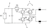
On the input terminal 2 of inverter 1, be connected a filtering capacitor C or holding capacitor in parallel with described solar generator.Described solar generator SG and capacitor C form intermediate DC circuit DC-circuit in other words.Described inverter has a H-electric bridge 3 that has four thyristor V1-V4 and an extra switch V5.Be connected with free wheeling diode D1-D5 in parallel with described switch element V1-V5.In electric bridge branch, be provided with two choke L1 and L2 at AC portion.
With frequency of supply for example 50Hz the switch element V1 and the V3 on top triggered control, to the switch element V2 of bottom and V4 then with one in the kHz scope high impulse frequency of the 16kHz pulse-triggered of carrying out pulse width modulation for example.
The additional thyristor V5 that particularly also can be designed to the MOSFET member with the lower switches element receive the 16kHz of high impulse frequency-for example-pulse (triggerings) act on.Described switch element V5 switch element V1 insert in the half-wave of supply power voltage wherein with switch element V4 synchronously with pulse width modulation be subjected to pulse-triggered, as shown in Figure 2.Load current forms by switch element V5, V1 and V4 like this.If semiconductor switch V5 and V4 with dither synchronously close, then load current turns to/changes by V1 with self-oscillation approach that the antiparallel diode D3 of V3 constitutes along one.
As shown in Figure 3, in another half-wave of supply power voltage (negative half-wave), wherein switch element V3 connects, and switch element V5 and switch element V2 synchronously and pulse width modulation be subjected to pulse-triggered.This moment, load current formed by switch element V5, V3 and V2.If disconnect switch element V5 and V2 that high-frequency impulse triggers synchronously, then load current turns on the free wheeling diode D1 in parallel of switch element V1, as shown in Figure 4.
The terminal of load circuit from generator is separated from by means of a switch element V5 who is arranged in the DC circuit according to the present invention thus, avoids the component of voltage of high frequency to occur on the described terminal circuit thus.Therefore described switch element V5 is also as the additional disconnect of dc terminal with respect to the interchange end.Another dc terminal can break away from alternating current circuit by switch V2 or V4 similarly and be connected.
Here importantly, the distribution voltage by switch element V5 and V2 or V4 symmetry.Preferred thus switch element or the diode element that use with identical characteristics.
By this self-oscillation, reduce the current fluctuation among power choke coil L1 and the L2 and reduce the loss of magnetic reversals thus in addition.
Can realize the inverter of a kind of low-loss, transless and cost optimum simply by the present invention, described inverter can not cause High-frequency Interference in DC circuit.
The reference number table
1 inverter
2 input terminals
3 electric bridges
The SG solar engine
The switch element of V1-V4 bridge circuit
The self-oscillation element of D1-D4 bridge circuit
The D5 diode
V5 disconnect (switch element)
The C commutation condenser
The L1-L2 power choke coil
R
LastLoad resistance
L
LastLoad inductance
Claims (11)
1. method that is used for the direct voltage of one photoelectricity DC power supply being converted to alternating voltage with certain frequency by a bridge circuit with four switch elements (V1-V4) and four self-oscillation elements (D1-D4), wherein said switch element (V1-V4) is used the frequency of supply Pulse-trigger control, or trigger by high-frequency impulse, in the method, use a DC circuit, one alternating current circuit and a plurality of self-oscillation stage, it is characterized in that, during the described self-oscillation stage, described alternating current circuit breaks away from described DC circuit by means of an additional switch element that is arranged in the described DC circuit and is connected, wherein the next self-oscillation electric current of the state that connects in described disengaging in described bridge circuit flows through (D1-D4) in the described self-oscillation element, come to trigger the described switch element (V1-V4) of the described bridge circuit of control so asymmetricly, so that the switch element (V1 or V3) of electric bridge half one on top is by the frequency of supply Pulse-trigger control, and the switch element (V2 or V4) of electric bridge half one of bottom is triggered by described high-frequency impulse, the additional switch element (V5) that is arranged in described DC circuit of electric bridge half one of a half-wave and bottom by pulsed switch element (V2) synchronously by pulse-triggered, and in another half-wave with another switch element (V4) of electric bridge half one of bottom synchronously by pulse-triggered, wherein, under the state that break away to connect, the self-oscillation electric current flows through in the self-oscillation element (D1 or D3) of electric bridge half one on top.
2. method according to claim 1 is characterized in that, realizes reducing resonance by at least one choke in described alternating current circuit.
3. method according to claim 2 is characterized in that, realizes reducing resonance by two series connection and choke (L1, L2) that be arranged on the different bridge tap heads in described alternating current circuit.
4. method according to claim 1 and 2 is characterized in that, described method is applied in the transformerless photovoltaic inverter (1).
5. method according to claim 1 is characterized in that, the switch element (V2, V4, V5) that described bridge circuit is triggered by high-frequency impulse accordingly in the scope of kHZ by pulse-triggered.
6. method according to claim 1 is characterized in that, the switch element (V2, V4, V5) that described bridge circuit is triggered by high-frequency impulse accordingly in the mode of pulse width modulation by pulse-triggered.
7. be used for implementing circuit configuration, have a bridge circuit and an additional switch element (V5) according to each described method of aforesaid right requirement.
8. circuit configuration according to claim 7 is characterized in that, described additional switch element (V5) is provided with an antiparallel diode (D5).
9. according to claim 7 or 8 described circuit configurations, it is characterized in that the switch element of described bridge circuit (V1-V4) is designed to the MOSFET semiconductor component.
10. circuit configuration according to claim 9 is characterized in that, the switch element (V2, V4) and the described additional switch element (V5) that have only high-frequency impulse to trigger are designed to the MOSFET semiconductor component.
Be used for implementing it is characterized in that having transformerless design 11. have according to the structure of each described method of claim 1 to 6 or according to the inverter of each circuit configuration in the claim 7 to 10.
Applications Claiming Priority (2)
| Application Number | Priority Date | Filing Date | Title |
|---|---|---|---|
| DE102004030912.4 | 2004-06-25 | ||
| DE102004030912A DE102004030912B3 (en) | 2004-06-25 | 2004-06-25 | Method for converting a direct electrical voltage of a DC voltage source, in particular a photovoltaic DC voltage source into an AC voltage |
Publications (2)
| Publication Number | Publication Date |
|---|---|
| CN1713503A CN1713503A (en) | 2005-12-28 |
| CN100466446C true CN100466446C (en) | 2009-03-04 |
Family
ID=35063393
Family Applications (1)
| Application Number | Title | Priority Date | Filing Date |
|---|---|---|---|
| CNB2005100799231A Active CN100466446C (en) | 2004-06-25 | 2005-06-27 | Method of converting a direct current voltage from a source of direct current voltage into a alternating current voltage |
Country Status (8)
| Country | Link |
|---|---|
| US (1) | US7411802B2 (en) |
| EP (2) | EP1626494B1 (en) |
| JP (1) | JP4258739B2 (en) |
| CN (1) | CN100466446C (en) |
| AT (1) | ATE489767T1 (en) |
| DE (2) | DE102004030912B3 (en) |
| ES (1) | ES2354614T3 (en) |
| HK (1) | HK1084248A1 (en) |
Cited By (1)
| Publication number | Priority date | Publication date | Assignee | Title |
|---|---|---|---|---|
| CN102624274A (en) * | 2011-01-30 | 2012-08-01 | 上海康威特吉能源技术有限公司 | Interleaving parallel grid-connected inverter and control method thereof |
Families Citing this family (84)
| Publication number | Priority date | Publication date | Assignee | Title |
|---|---|---|---|---|
| ES2541772T3 (en) * | 2006-07-31 | 2015-07-24 | Ingeteam Power Technology, S.A. | Single phase inverter circuit for conditioning and converting direct current electrical energy into alternating current electrical energy |
| DE102007028077B4 (en) | 2007-06-15 | 2009-04-16 | Sma Solar Technology Ag | Device for feeding electrical energy into a power supply network and DC-DC converter for such a device |
| DE102007028078B4 (en) | 2007-06-15 | 2009-04-16 | Sma Solar Technology Ag | Device for feeding electrical energy into a power supply network and DC-DC converter for such a device |
| DE102007030577A1 (en) | 2007-06-29 | 2009-01-02 | Sma Solar Technology Ag | Inverter for feeding electrical energy into a power supply network |
| EP2023475B1 (en) | 2007-08-04 | 2016-10-12 | SMA Solar Technology AG | Inversion for a grounded DC source, in particular a photovoltaic generator |
| DE102007038959A1 (en) | 2007-08-14 | 2009-02-26 | Sma Solar Technology Ag | inverter |
| DE102007038960A1 (en) | 2007-08-14 | 2009-02-26 | Sma Solar Technology Ag | inverter |
| DE102007058633B4 (en) | 2007-10-19 | 2009-12-24 | Diehl Ako Stiftung & Co. Kg | Method for operating an inverter |
| EP2051364A3 (en) | 2007-10-19 | 2016-08-10 | Diehl AKO Stiftung & Co. KG | Method for operating an inverter |
| EP2051357B1 (en) * | 2007-10-19 | 2009-12-16 | SMA Solar Technology AG | Inverter, in particular for solar panel assemblies |
| ITMI20080463A1 (en) * | 2008-03-19 | 2009-09-20 | Unaohm Technology Srl | MEASUREMENT INSTRUMENT FOR PHOTOVOLTAIC SYSTEMS |
| EP2107672A1 (en) * | 2008-03-31 | 2009-10-07 | SMA Solar Technology AG | Three-phase inverter without connection between the neutral conductor of the grid and the mid-point of the intermediate circuit |
| AU2008357911B2 (en) | 2008-06-17 | 2013-10-17 | Ingeteam Power Technology, S.A. | Control method for a structure converting direct current into alternating current |
| EP2136465B1 (en) | 2008-06-18 | 2017-08-09 | SMA Solar Technology AG | Inverter realized by a bridge circuit comprising slow and fast clocked switches |
| EP2342807B1 (en) | 2008-09-24 | 2015-03-18 | SMA Solar Technology AG | Converter with at least one normally-on switch |
| DE102008048841B8 (en) * | 2008-09-25 | 2010-06-10 | Fraunhofer-Gesellschaft zur Förderung der angewandten Forschung e.V. | Isolating circuit for inverter |
| WO2010061392A1 (en) * | 2008-11-30 | 2010-06-03 | Shaul Ozeri | Apparatus and method for processing power signals |
| DE502008001346D1 (en) | 2008-12-23 | 2010-10-28 | Sma Solar Technology Ag | Electric circuit with self-conducting semiconductor switch |
| DE102008063201A1 (en) | 2008-12-29 | 2010-07-22 | Martin Weinmann | Method and circuit arrangement for feeding the voltage intermediate circuit of an inverter |
| US20100191489A1 (en) * | 2009-01-28 | 2010-07-29 | Uqm Technologies, Inc. | Distributed Generation Power System |
| CA2655007C (en) | 2009-02-20 | 2017-06-27 | Queen's University At Kingston | Photovoltaic cell inverter |
| EP2226926A1 (en) | 2009-03-02 | 2010-09-08 | ABB Research Ltd. | Five-level inverter |
| EP2237403A1 (en) * | 2009-03-30 | 2010-10-06 | SMA Solar Technology AG | Inverter with two asymmetric bridges and a free-wheeling path decoupling the DC input from the AC output |
| DE102009002856A1 (en) * | 2009-05-06 | 2015-03-26 | Robert Bosch Gmbh | Inverter assembly |
| DE102009002860A1 (en) * | 2009-05-06 | 2010-11-18 | Robert Bosch Gmbh | Inverter arrangement with a decoupling switching element |
| BRPI0903548B1 (en) * | 2009-06-05 | 2019-06-25 | Indústria De Motores Anauger S.a | FEEDING SYSTEM FOR AN INDUCTIVE LOAD FROM AN ENERGY SOURCE WITH VARIABLE POWER AND FEEDING SYSTEM FOR A VIBRATING PUMP FROM SOLAR CELLS |
| IT1394558B1 (en) * | 2009-06-08 | 2012-07-05 | Ca To Bo S N C Di Cavalleretti Lavia & Tondelloni Daniele | DC-AC CONVERTER, IN PARTICULAR TO PROVIDE ELECTRIC ENERGY FROM A SOLAR PANEL TO AN ELECTRIC NETWORK |
| EP2270971A1 (en) * | 2009-07-02 | 2011-01-05 | ABB Research Ltd. | Three-stage multilevel DC to AC converter |
| TWI385509B (en) * | 2009-07-23 | 2013-02-11 | Feeling Technology Corp | Control circuit for power supplying |
| DE102009029387A1 (en) | 2009-09-11 | 2011-03-24 | Robert Bosch Gmbh | DC-AC inverter arrangement, in particular solar cell inverter |
| EP2309639B1 (en) | 2009-10-09 | 2016-02-10 | SMA Solar Technology AG | Reactive power-capable inverter |
| US7990743B2 (en) * | 2009-10-20 | 2011-08-02 | General Electric Company | System and method for decreasing solar collector system losses |
| US7855906B2 (en) * | 2009-10-26 | 2010-12-21 | General Electric Company | DC bus voltage control for two stage solar converter |
| DE102010008426B4 (en) * | 2010-02-18 | 2011-09-01 | Hochschule Konstanz | 3-stage pulse inverter with discharge network |
| US8050062B2 (en) * | 2010-02-24 | 2011-11-01 | General Electric Company | Method and system to allow for high DC source voltage with lower DC link voltage in a two stage power converter |
| CN102934346A (en) | 2010-06-07 | 2013-02-13 | Abb公司 | Inverter for solar cell array |
| US9035626B2 (en) | 2010-08-18 | 2015-05-19 | Volterra Semiconductor Corporation | Switching circuits for extracting power from an electric power source and associated methods |
| CN101951193A (en) * | 2010-09-16 | 2011-01-19 | 薛韬 | Cellular photovoltaic power station |
| DE102011003859A1 (en) * | 2011-02-09 | 2012-08-09 | Robert Bosch Gmbh | System for charging an energy storage and method for operating the charging system |
| DE102011017601A1 (en) * | 2011-04-27 | 2012-10-31 | Robert Bosch Gmbh | Control method for an inverter and inverter arrangement, in particular solar cell inverter |
| US8937822B2 (en) | 2011-05-08 | 2015-01-20 | Paul Wilkinson Dent | Solar energy conversion and utilization system |
| US11901810B2 (en) | 2011-05-08 | 2024-02-13 | Koolbridge Solar, Inc. | Adaptive electrical power distribution panel |
| US11460488B2 (en) | 2017-08-14 | 2022-10-04 | Koolbridge Solar, Inc. | AC electrical power measurements |
| CN102185511B (en) * | 2011-05-09 | 2013-04-24 | 浙江金贝能源科技有限公司 | Noninsulated type converting circuit from direct-current voltage to alternating-current voltage |
| DE102011077160A1 (en) * | 2011-06-07 | 2012-12-13 | Semikron Elektronik Gmbh & Co. Kg | Solar module and method for its operation |
| TWI436574B (en) * | 2011-07-13 | 2014-05-01 | Delta Electronics Inc | Dc to ac converter |
| CN102882398B (en) * | 2011-07-13 | 2016-02-03 | 台达电子工业股份有限公司 | DC-AC converter |
| CN103036463A (en) * | 2011-10-10 | 2013-04-10 | 艾伏新能源科技(上海)股份有限公司 | High efficiency single-phase photovoltaic grid-connected inverter |
| DE102011116593B4 (en) | 2011-10-21 | 2014-11-13 | Diehl Ako Stiftung & Co. Kg | Inverter with asymmetrical chokes and a control unit for asymmetric operation of the chokes |
| CN102437766A (en) * | 2011-10-25 | 2012-05-02 | 阳光电源股份有限公司 | Single-phase inverter |
| US8867248B2 (en) | 2011-12-20 | 2014-10-21 | Kohler Co. | High-efficiency, three-level, single-phase inverter |
| TW201340537A (en) | 2012-03-21 | 2013-10-01 | Ind Tech Res Inst | Method of controlling photovoltaic apparatus for AC output and AC photovoltaic apparatus |
| CN104170226A (en) | 2012-05-22 | 2014-11-26 | 株式会社安川电机 | Power conversion apparatus |
| WO2014004575A1 (en) | 2012-06-25 | 2014-01-03 | Arizona Board Of Regents, For And On Behalf Of Arizona State University | Circuits and methods for photovoltaic inverters |
| US9595888B2 (en) | 2012-11-29 | 2017-03-14 | General Electric Company | System and method to avoid reverse recovery in a power converter |
| CN103051224B (en) * | 2012-12-24 | 2015-03-04 | 江苏兆伏新能源有限公司 | Reactive power control method of contravariant topology circuit |
| CN103326606B (en) * | 2013-06-09 | 2015-08-26 | 浙江大学 | A kind of one-phase five-level inverter |
| DE102013211121A1 (en) | 2013-06-14 | 2014-12-18 | Robert Bosch Gmbh | inverter |
| CN104079227B (en) * | 2014-07-16 | 2016-09-07 | 浙江大学 | A kind of have the electric system reducing common mode disturbances ability |
| CN104242719B (en) * | 2014-08-07 | 2016-11-09 | 东南大学 | The full-bridge non-isolated grid-connected inverter of type without switching loss and switch control time sequence |
| US9584034B2 (en) | 2014-09-08 | 2017-02-28 | Infineon Technologies Austria Ag | Power converter circuit and method with asymmetrical half bridge |
| US9837921B2 (en) | 2014-09-08 | 2017-12-05 | Infineon Technologies Austria Ag | Multi-cell power conversion method and multi-cell power converter |
| US9762134B2 (en) | 2014-09-08 | 2017-09-12 | Infineon Technologies Austria Ag | Multi-cell power conversion method and multi-cell power converter |
| US9929662B2 (en) | 2014-09-08 | 2018-03-27 | Infineon Technologies Austria Ag | Alternating average power in a multi-cell power converter |
| CN104158427B (en) * | 2014-09-10 | 2016-10-19 | 哈尔滨工业大学 | Single-phase transless isolated form Z source photovoltaic combining inverter and modulator approach |
| CN104218839B (en) * | 2014-09-28 | 2017-09-29 | 四川长虹电源有限责任公司 | Multi-electrical level inverter |
| US9755537B2 (en) | 2015-03-04 | 2017-09-05 | Infineon Technologies Austria Ag | Multi-cell power conversion method with failure detection and multi-cell power converter |
| US10749430B2 (en) | 2015-03-13 | 2020-08-18 | Positec Power Tools (Suzhou) Co., Ltd. | Power transmission apparatus and control method therefor, and power supply system |
| PL229067B1 (en) | 2015-04-24 | 2018-06-29 | Spirvent Spolka Z Ograniczona Odpowiedzialnoscia | Circuit of the DC/DC/AC converter |
| CN104901572A (en) * | 2015-06-05 | 2015-09-09 | 上海大学 | High-power-density and long-life fly-back micro photovoltaic grid-connected inverter |
| DE102015113247A1 (en) * | 2015-08-11 | 2017-02-16 | Sma Solar Technology Ag | Inverter with a discharge capacitor and photovoltaic system comprising an inverter |
| WO2017096355A1 (en) | 2015-12-04 | 2017-06-08 | Arizona Board Of Regents On Behalf Of Arizona State University | Power converter circuitry for photovoltaic devices |
| DE102015122636B4 (en) | 2015-12-22 | 2017-07-13 | Sma Solar Technology Ag | Inverter with mains separation point and insulation resistance measurement as well as method for measuring an insulation resistance |
| CN105471300B (en) * | 2015-12-25 | 2017-12-29 | 北京交通大学 | H5 D types non-isolated grid-connected inverters and its modulator approach |
| US10381953B2 (en) | 2016-10-26 | 2019-08-13 | The University Of Manitoba | Bi-directional electric power conversion circuit with bridgeless buck-boost circuit and reconfigurable capacitor-inductor filter circuit |
| CN106655972B (en) * | 2016-12-26 | 2019-06-18 | 华中科技大学 | A kind of converter system and the stator DC excitation electromotor with the system |
| US10153697B2 (en) * | 2017-04-10 | 2018-12-11 | Infineon Technologies Austria Ag | Multiphase power supply and failure mode protection |
| CN107612394B (en) | 2017-09-12 | 2019-11-22 | 爱士惟新能源技术(江苏)有限公司 | Control processing method for the DC-to-AC converter with H5 topological structure |
| EP3462593A1 (en) | 2017-10-02 | 2019-04-03 | ABB Schweiz AG | Electrical inverter with low common mode voltage |
| US10038393B1 (en) * | 2017-11-02 | 2018-07-31 | National Chung-Shan Institute Of Science & Technology | Single-phase non-isolated inverter |
| CN109617493A (en) * | 2018-11-30 | 2019-04-12 | 展鹏科技股份有限公司 | A kind of switch controlling device and frequency converter of frequency conversion output |
| CN109765960B (en) * | 2019-03-04 | 2020-08-28 | 上海数明半导体有限公司 | Maximum power tracking power generation device and system |
| CN110707952A (en) * | 2019-11-05 | 2020-01-17 | 武汉武水电气技术有限责任公司 | Photovoltaic grid-connected inverter |
| WO2023219595A1 (en) | 2022-05-12 | 2023-11-16 | Aselsan Elektroni̇k Sanayi̇ Ve Ti̇caret Anoni̇m Şi̇rketi̇ | Transformerless 3-phase, 3-level t-type npc unfolding inverter with 3 hf switches on dc side |
Citations (3)
| Publication number | Priority date | Publication date | Assignee | Title |
|---|---|---|---|---|
| CN1008867B (en) * | 1986-01-13 | 1990-07-18 | 株式会社日立制作所 | The control device of pulse width modulated inverter |
| US5896282A (en) * | 1996-03-21 | 1999-04-20 | Amsdell Inc. | Inverter circuit and integrated uninterruptible power supply protection system |
| US6256209B1 (en) * | 1997-10-28 | 2001-07-03 | Nada Electronics Limited | AC to DC conversion arrangement |
Family Cites Families (9)
| Publication number | Priority date | Publication date | Assignee | Title |
|---|---|---|---|---|
| GB2179477B (en) * | 1985-08-23 | 1989-03-30 | Ferranti Plc | Power supply circuit |
| JP2680345B2 (en) * | 1988-05-09 | 1997-11-19 | 株式会社東芝 | Power supply device by PWM control |
| DE19732218C1 (en) * | 1997-07-26 | 1999-03-18 | Dirk Schekulin | Transformerless ac. inverter circuit, for coupling photovoltaic systems or wind generator systems, esp. in the low power range, to current networks |
| US6031749A (en) * | 1999-03-31 | 2000-02-29 | Vari-Lite, Inc. | Universal power module |
| EP1442512A2 (en) * | 2001-11-05 | 2004-08-04 | Siemens AG Österreich | Voltage converter |
| US7126294B2 (en) * | 2002-01-31 | 2006-10-24 | Ebara Corporation | Method and device for controlling photovoltaic inverter, and feed water device |
| JP3833133B2 (en) * | 2002-02-19 | 2006-10-11 | 株式会社ダイヘン | Power supply device for arc machining |
| DE10221592A1 (en) * | 2002-05-15 | 2003-12-04 | Fraunhofer Ges Forschung | Current inverter for direct/alternating currents, has direct and alternating connections with an intermediate power store, a bridge circuit, rectifier diodes and a inductive choke |
| DE10312921A1 (en) * | 2003-03-22 | 2004-10-14 | Sma Regelsysteme Gmbh | Circuit arrangement, additional module and solar system |
-
2004
- 2004-06-25 DE DE102004030912A patent/DE102004030912B3/en active Active
-
2005
- 2005-06-01 EP EP05011807A patent/EP1626494B1/en active Active
- 2005-06-01 DE DE502005010571T patent/DE502005010571D1/en active Active
- 2005-06-01 EP EP10183310.1A patent/EP2290797B1/en active Active
- 2005-06-01 ES ES05011807T patent/ES2354614T3/en active Active
- 2005-06-01 AT AT05011807T patent/ATE489767T1/en active
- 2005-06-16 US US11/154,094 patent/US7411802B2/en active Active
- 2005-06-23 JP JP2005182954A patent/JP4258739B2/en active Active
- 2005-06-27 CN CNB2005100799231A patent/CN100466446C/en active Active
-
2006
- 2006-04-07 HK HK06104248.6A patent/HK1084248A1/en unknown
Patent Citations (3)
| Publication number | Priority date | Publication date | Assignee | Title |
|---|---|---|---|---|
| CN1008867B (en) * | 1986-01-13 | 1990-07-18 | 株式会社日立制作所 | The control device of pulse width modulated inverter |
| US5896282A (en) * | 1996-03-21 | 1999-04-20 | Amsdell Inc. | Inverter circuit and integrated uninterruptible power supply protection system |
| US6256209B1 (en) * | 1997-10-28 | 2001-07-03 | Nada Electronics Limited | AC to DC conversion arrangement |
Cited By (1)
| Publication number | Priority date | Publication date | Assignee | Title |
|---|---|---|---|---|
| CN102624274A (en) * | 2011-01-30 | 2012-08-01 | 上海康威特吉能源技术有限公司 | Interleaving parallel grid-connected inverter and control method thereof |
Also Published As
| Publication number | Publication date |
|---|---|
| ES2354614T3 (en) | 2011-03-16 |
| EP1626494B1 (en) | 2010-11-24 |
| US7411802B2 (en) | 2008-08-12 |
| EP1626494A3 (en) | 2007-08-08 |
| EP2290797A3 (en) | 2013-10-23 |
| EP2290797B1 (en) | 2015-01-28 |
| JP4258739B2 (en) | 2009-04-30 |
| HK1084248A1 (en) | 2006-07-21 |
| EP2290797A2 (en) | 2011-03-02 |
| DE502005010571D1 (en) | 2011-01-05 |
| CN1713503A (en) | 2005-12-28 |
| JP2006014591A (en) | 2006-01-12 |
| ATE489767T1 (en) | 2010-12-15 |
| EP1626494A2 (en) | 2006-02-15 |
| US20050286281A1 (en) | 2005-12-29 |
| DE102004030912B3 (en) | 2006-01-19 |
Similar Documents
| Publication | Publication Date | Title |
|---|---|---|
| CN100466446C (en) | Method of converting a direct current voltage from a source of direct current voltage into a alternating current voltage | |
| CN101180787B (en) | Bi-directional battery power inverter | |
| KR100963725B1 (en) | Matrix converter apparatus | |
| JP4727882B2 (en) | Converter for converting electrical energy | |
| US7239530B1 (en) | Apparatus for isolated switching power supply with coupled output inductors | |
| US8009443B2 (en) | DC/DC converter and AC/DC converter | |
| JP5065188B2 (en) | Series resonant converter | |
| US5694307A (en) | Integrated AC/DC and DC/DC converter | |
| KR20090085023A (en) | Device for feeding electric energy into a power grid and dc converter for such a device | |
| CN104242709A (en) | Multi-level inverter | |
| JP2009539337A (en) | Inverter circuit | |
| CN112117903A (en) | Single-stage isolation DC-DC converter | |
| CN103299530A (en) | Assembly for converting an input AC voltage to an output AC voltage | |
| CN102055365A (en) | Converter device and uninterruptible power supply comprising such a device | |
| CN115868105A (en) | Soft switching pulse width modulation DC-DC power converter | |
| JP2014522231A (en) | Inverter with coupling inductance | |
| KR20140096260A (en) | Double rectifier for multi-phase contactless energy transfer system | |
| US20140286059A1 (en) | Sparse and ultra-sparse partial resonant converters | |
| JP5040585B2 (en) | Power conversion system | |
| KR101595927B1 (en) | Dc-dc converter circuit | |
| US20180309357A1 (en) | System for converting a dc electric power into an ac electric power with an energy recovery module | |
| JP2013516153A (en) | Groundable DC / DC converter | |
| US20110140681A1 (en) | Direct dc converter (dc chopper) | |
| JP4939819B2 (en) | Three-phase rectifier | |
| US20240055858A1 (en) | Method and circuit for an integrated dc converter in an ac battery |
Legal Events
| Date | Code | Title | Description |
|---|---|---|---|
| C06 | Publication | ||
| PB01 | Publication | ||
| C10 | Entry into substantive examination | ||
| SE01 | Entry into force of request for substantive examination | ||
| REG | Reference to a national code |
Ref country code: HK Ref legal event code: DE Ref document number: 1084248 Country of ref document: HK |
|
| C14 | Grant of patent or utility model | ||
| GR01 | Patent grant | ||
| REG | Reference to a national code |
Ref country code: HK Ref legal event code: GR Ref document number: 1084248 Country of ref document: HK |