WO2019131229A1 - Power control device, power control method, and program - Google Patents
Power control device, power control method, and program Download PDFInfo
- Publication number
- WO2019131229A1 WO2019131229A1 PCT/JP2018/046185 JP2018046185W WO2019131229A1 WO 2019131229 A1 WO2019131229 A1 WO 2019131229A1 JP 2018046185 W JP2018046185 W JP 2018046185W WO 2019131229 A1 WO2019131229 A1 WO 2019131229A1
- Authority
- WO
- WIPO (PCT)
- Prior art keywords
- power
- frequency
- storage system
- discharging
- storage
- Prior art date
Links
Images


Classifications
-
- H—ELECTRICITY
- H02—GENERATION; CONVERSION OR DISTRIBUTION OF ELECTRIC POWER
- H02J—CIRCUIT ARRANGEMENTS OR SYSTEMS FOR SUPPLYING OR DISTRIBUTING ELECTRIC POWER; SYSTEMS FOR STORING ELECTRIC ENERGY
- H02J3/00—Circuit arrangements for ac mains or ac distribution networks
- H02J3/28—Arrangements for balancing of the load in a network by storage of energy
- H02J3/32—Arrangements for balancing of the load in a network by storage of energy using batteries with converting means
-
- H—ELECTRICITY
- H02—GENERATION; CONVERSION OR DISTRIBUTION OF ELECTRIC POWER
- H02J—CIRCUIT ARRANGEMENTS OR SYSTEMS FOR SUPPLYING OR DISTRIBUTING ELECTRIC POWER; SYSTEMS FOR STORING ELECTRIC ENERGY
- H02J13/00—Circuit arrangements for providing remote indication of network conditions, e.g. an instantaneous record of the open or closed condition of each circuitbreaker in the network; Circuit arrangements for providing remote control of switching means in a power distribution network, e.g. switching in and out of current consumers by using a pulse code signal carried by the network
Definitions
- the present disclosure relates to a power control apparatus that controls power, a power control method, and a program.
- the apparatus includes, for example, a solar battery, a storage battery, a distributed power supply such as a fuel cell, and a home appliance.
- a control device is connected to the upper level smart server.
- the smart server centrally manages a plurality of consumers (see, for example, Patent Document 1).
- the power management system controls the storage system connected to the power system in the customer, but when the group management system further controls a plurality of power management systems, the group management system goes through the power management system according to the increase or decrease of the power demand. Charge and discharge each storage system. However, if a plurality of power storage systems are charged and discharged together, power fluctuations may become large and the power system may become unstable. Therefore, control of the fluctuation speed of the power according to the fluctuation of the power demand is required.
- the present disclosure has been made in view of such circumstances, and an object thereof is to provide a technique for controlling the rate of change of power according to the change in power demand.
- a power control apparatus is connected to a group management system that transmits a control command to a storage system group including a storage system installed in each of a plurality of customers.
- Another aspect of the present disclosure is a power control method.
- This method is connected to a group management system for transmitting a control command to a storage system group including a storage system installed in each of a plurality of customers, and a power control apparatus for controlling the storage system installed in the customers. And detecting the difference between the frequency of the electric power system or the frequency of the electric power system with respect to the reference frequency, the electric power to be charged and discharged to the electric storage system based on the detected frequency or the difference, and Generating information regarding a time to start charging and discharging.
- FIG. 1 is a diagram showing a configuration of a VPP system according to a first embodiment. It is a figure which shows the structure of the consumer of FIG. It is a figure which shows the data structure of the table memorize
- FIG. 7 is a diagram showing a data structure of a table stored in a storage unit according to a second embodiment.
- An embodiment relates to a power management system that controls charging and discharging of a storage system connected to a power system according to an increase or decrease in power demand in the power system.
- the storage system is installed in each customer along with devices such as a solar power generation system and a fuel cell system.
- the customer is a facility receiving power supply from a power company or the like, and is, for example, a house, an office, a store, a factory, a park, or the like.
- the power management system discharges the storage system in a time zone in which the consumer consumes a large amount of power, or charges the storage system at night when the electricity bill of the power system is inexpensive.
- VPP Virtual Power Plant
- VPP integrates and controls equipment such as small-scale solar power generation systems, power storage systems, fuel cell systems, etc., which are scattered, with power demand suppression.
- the VPP controls devices such as a photovoltaic power generation system, a storage system, and a fuel cell system via a network to make them function as a single power plant.
- VPP multiple power management systems are connected to a group management system.
- the group management system is connected to a host system which is an aggregator that integrates a plurality of group management systems.
- a VPP is equivalent to the upper system and the group management system plus equipment such as a storage system installed in the customer.
- the higher-level system trades power in the market or in a relative contract with the business operator.
- the higher-level system provides integrated coordination power to the power exchange market, the power transmission and distribution department of the power company, the retail power company, and the like. Therefore, the higher-level system determines the coordination power to be provided to the market or each business operator, and distributes the coordination power to each group management system.
- Each group management system further distributes coordination to each customer.
- the group management system instructs each of the plurality of power management systems to control to sell or buy power in response to a request from the upper system. For example, the group management system requests the power management system to control the storage system to be discharged or to reduce the power consumption of the customer when the power generated by the power plant becomes tight.
- a plurality of power management systems are connected to the group management system, and one or more power storage systems are connected to each power management system, which are arranged hierarchically. Therefore, it can be said that the group management system controls fluctuations in power due to a plurality of power storage systems (hereinafter also referred to as "power storage system group").
- the fluctuation of the power demand in the electric power system is indicated by the combination of a minute fluctuation, a short cycle component and a long cycle component in which fluctuation cycles are mutually different. The proportions of these combinations vary depending on the situation, for example, the power demand fluctuates and increases.
- the group management system charges and discharges a plurality of power storage systems simultaneously in response to the increase and decrease of the power demand, the fluctuation of the power becomes large and the power system becomes unstable. Therefore, it is desirable that the rate of change of the power be adjusted according to the rate of increase or decrease of the power demand.
- each power management system in this embodiment determines the charge / discharge start time of charge / discharge so that the number of charge / discharge power storage systems changes with the passage of time, Charge / discharge power is adjusted based on the detected power system frequency.
- Each power management system causes the storage system to execute charge / discharge of charge / discharge power when charge / discharge start time of charge / discharge comes.
- the power system frequency detected in each power management system is common, and uses a table generated in the upper system or the group management server. Therefore, control in each power management system is common.
- FIG. 1 shows the configuration of the VPP system 100.
- the VPP system 100 includes a host system server 10 and a group management system server 12 collectively referred to as a first group management system server 12a, a second group management system server 12b, an Mth group management system server 12m and a power management system server 14 generically.
- the first power management system server 14a is installed in the first customer 16a
- the second power management system server 14b is installed in the second customer 16b
- the Nth power management system server 14n is the Nth customer 16n.
- the first customer 16a, the second customer 16b, and the N-th customer 16n are collectively referred to as the customer 16.
- the number of group management system servers 12 is not limited to "M”
- the number of power management system servers 14 and customers 16 is not limited to "N".
- the customer 16 is, for example, a single-family house, an apartment house such as an apartment, a store such as a convenience store or a supermarket, a commercial facility such as a building, a factory. It is an existing facility.
- the customer 16 is provided with equipment such as an air conditioner (air conditioner), a television receiver (television), a lighting device, a storage system, and a heat pump water heater. These devices receive the supply of commercial power and consume power by being connected to a power system such as a power company.
- a power system such as a power company.
- the device may include a renewable energy generator such as a solar cell system or a fuel cell system.
- the power management system server 14 is a computer for executing the processing of the power management system, and is installed, for example, in the customer 16.
- the power management system server 14 has, for example, a function as a home energy management system (HEMS) controller. Therefore, the power management system server 14 can communicate with various devices in the customer 16 by HAN (Home Area Network), and controls these devices.
- the power management system server 14 controls the operation of the storage system, for example, discharge and charge.
- the power management system server 14 may control the interconnection between the devices installed in the customer 16 and the power system.
- the power management system server 14 disconnects between the device and the power system at the time of power failure, and interconnects between the device and the power system at the time of power recovery.
- the group management system server 12 is a computer for executing the processing of the group management system.
- the group management system server 12 manages a plurality of power management system servers 14 by connecting a plurality of power management system servers 14.
- the group management system server 12 centrally manages a plurality of devices connected to each of the plurality of power management system servers 14.
- the group management system server 12 may transmit a control command to a storage system group including a storage system installed in each of the plurality of customers 16.
- the plurality of group management system servers 12 are connected to the upper system server 10.
- the upper system server 10 is a computer for executing the processing of the upper system which is an aggregator.
- the VPP including the upper system and the group management system trades power in the market or in a relative contract with the business operator, and the upper system server 10 sends the group management system server 12 a request according to the contract. Output.
- One group management system server 12 may be connected to a plurality of upper system servers 10.
- the group management system server 12 when the power demand in the power system is tight, the group management system server 12 causes the power discharged from the storage system to be consumed in the customer 16 or suppresses the power consumption in the customer 16. Control the power management system server 14 to In addition, when the power supply in the power system exceeds the power demand, the group management system server 12 increases the charge to the storage system or increases the demand in the customer 16. Control.
- FIG. 2 shows the configuration of the customer 16.
- the customer 16 is provided with a power system 30, a smart meter 32, a distribution board 34, a load 36, a storage system 40, and a power management system server 14, for example, a first power management system server 14a.
- the storage system 40 includes a storage battery (SB) 210, a DC / DC 212 for SB, a bi-directional DC / AC inverter 214, and a control device 216.
- the first power management system server 14a includes a service cooperation unit 300 and a control unit 302.
- the service cooperation unit 300 includes a reception unit 510 and a transmission unit 512.
- the control unit 302 includes a frequency detection unit 600, a storage unit 602, A generation unit 604, a transmission unit 606, and a reception unit 608 are included. Furthermore, a group management system server 12, for example, a first group management system server 12a is connected to the first power management system server 14a via the network 18. Although a solar cell system, a heat pump water heater, etc. may be installed in the customer 16, these are omitted here.
- the power demand in the power system 30 is indicated by the combination of a minute variation, a short period component, and a long period component, which have different variation cycles.
- the minute change component has a change period of about several tens of seconds
- the short period component has a change period of about several minutes
- the long period component has a change period of about several tens of minutes. That is, the variation period of the minute variation is the shortest, and the variation period of the long period component is the longest.
- the smart meter 32 is connected to the power system 30 and is a digital power meter.
- the smart meter 32 can measure the amount of power of the current flowing from the power system 30 and the amount of power of the reverse current flowing out of the power system 30.
- the smart meter 32 has a communication function and can communicate with the power management system server 14.
- the distribution line 42 connects the smart meter 32 and the distribution board 34.
- the distribution board 34 is connected to the distribution line 42 and also connects the load 36.
- the distribution board 34 supplies power to the load 36.
- the load 36 is a device that consumes the power supplied via the distribution line 42.
- the load 36 includes equipment such as a refrigerator, an air conditioner, and lighting.
- one load 36 is connected to the distribution board 34, a plurality of loads 36 may be connected to the distribution board 34.
- the SB 210 is a storage battery capable of charging and discharging electric power, and includes a lithium ion storage battery, a nickel hydrogen storage battery, a lead storage battery, an electric double layer capacitor, a lithium ion capacitor, and the like.
- the SB 210 is connected to the DC / DC 212 for SB.
- the SB DC / DC 212 is a DC-DC converter, and performs conversion between the DC power on the SB 210 side and the DC power on the bidirectional DC / AC inverter 214 side.
- the bi-directional DC / AC inverter 214 is connected between the DC / DC 212 for SB and the distribution board 34.
- the bidirectional DC / AC inverter 214 converts AC power from the distribution board 34 into DC power, and outputs the converted DC power to the SB DC / DC 212.
- the bidirectional DC / AC inverter 214 converts the DC power from the SB DC / DC 212 into AC power, and outputs the converted AC power to the distribution board 34. That is, the SB 210 is charged and discharged by the bi-directional DC / AC inverter 214.
- the control of the bi-directional DC / AC inverter 214 is performed by the controller 216.
- the SB 210, the SB DC / DC 212, the bidirectional DC / AC inverter 214, and the control device 216 may be stored in one case, and even in that case, this is referred to as a storage system 40.
- the first power management system server 14 a is connected to the smart meter 32 and the storage system 40 via a network such as HAN, can communicate with each other, and controls the storage system 40 connected to the power system 30. It can be said that such a first power management system server 14a is a power control device. In the following, the communication between the first power management system server 14a and the smart meter 32 will not be described.
- the frequency detection unit 600 is connected to the power system 30.
- Frequency detection unit 600 detects the frequency of AC power in power system 30 (hereinafter, also referred to as “frequency of power system 30”).
- the frequency of the power system 30 becomes lower than the commercial power frequency when the power demand increases and runs short of power, and becomes higher than the commercial power frequency when the power demand decreases and the power becomes excessive.
- the commercial power supply frequency is, for example, a reference frequency defined at 50 Hz and 60 Hz.
- the frequency detection unit 600 may detect the difference in frequency of the power system 30 with respect to the commercial power supply frequency.
- the frequency detection unit 600 may be connected to the smart meter 32 or the distribution line 42 to detect the frequency of the power system 30.
- the frequency detection unit 600 may be provided in the storage system 40, and may transmit the detected frequency to the first power management system server 14a.
- Storage unit 602 holds related information in which the power to be charged / discharged to / from storage system 40 is associated with the frequency of power system 30.
- the related information instead of the frequency of the power system 30, the difference of the frequency of the power system 30 with respect to the commercial power supply frequency may be used.
- the related information is held, for example, in the form of a table, but may be held in the form of a relational expression.
- FIG. 3 shows the data structure of a table stored in the storage unit 602. As shown, the relationship of charge and discharge power to the detection frequency is shown.
- the commercial power supply frequency is 60 Hz.
- charge / discharge power When the detection frequency is higher than 60 Hz, that is, when the frequency of the power system 30 is higher than the commercial power supply frequency, charge / discharge power is defined that causes the storage system 40 to perform charging.
- charge / discharge power is defined that causes storage system 40 to perform discharge.
- the absolute value of charge / discharge power increases as the absolute value of the difference between the frequency of power system 30 and the commercial power source frequency increases, but the reason will be described later.
- the generation unit 604 refers to the table held in the storage unit 602 based on the frequency or difference detected by the frequency detection unit 600 to charge / discharge the power of the storage system 40 and charge / discharge the storage system 40. Information on the time to be started (hereinafter also referred to as “charge / discharge start time”) is generated. Even when the frequency of the power system 30 detected by the frequency detection unit 600 is lower than the commercial power supply frequency, the degree of the power shortage differs according to the magnitude of the deviation of these frequencies. For example, when the deviation of these frequencies is large, it can be said that the degree of the power shortage is larger than when the deviation of these frequencies is small.
- generation unit 604 Based on the frequency or difference detected by frequency detection unit 600, generation unit 604 extracts charge / discharge power to be charged / discharged by storage system 40 by referring to the related information stored in storage unit 602.
- the number of power storage systems 40 performing charging and discharging in the power storage system group is adjusted. Specifically, by increasing the number of power storage systems 40 being charged and discharged with the passage of time, it becomes possible to increase the power of charging and discharging with the passage of time. For example, 10 storage systems 40 are discharged at a predetermined charge / discharge start time, and an additional 10 storage systems 40 are discharged after a predetermined interval elapses, and an additional 10 storage systems after a predetermined interval elapses By discharging the storage system 40 of the above, the power to be discharged is increased.
- the storage system group achieves the target power after a predetermined period (hereinafter, referred to as “charging and discharging period”) has elapsed. Furthermore, even in the case where approximately the same number of storage systems 40 start discharging in order at regular intervals, if the discharge power of one storage system 40 increases, the speed of change of the power increases.
- the case of charging is similar to the case of discharging.
- the charging and discharging period until the storage system group reaches the target power is assumed to be a fixed value.
- a plurality of charge and discharge timings are arranged at regular intervals.
- the number of charge / discharge timings is also assumed to be a fixed value. This corresponds to the fact that the fixed interval is also a fixed value. Therefore, it is assumed that the timing which becomes the starting point of the charge and discharge period, the charge and discharge period, and the number of charge and discharge timings are determined in advance.
- the generation unit 604 generates a random number, for example, a pseudo random number. A well-known technique may be used to generate the random number, so the description is omitted here.
- the generation unit 604 in the plurality of power management system servers 14 generates a random number by a common method. Among the plurality of charge / discharge timings defined during the charge / discharge period, generation unit 604 specifies charge / discharge timing by using random numbers generated with a predetermined probability, thereby causing charge / discharge of storage system 40 to start charging. Generate discharge start time.
- the generation unit 604 When the charge / discharge period is 1 second and the number of charge / discharge timings is "10", the fixed interval is 0.1 second.
- the generation unit 604 generates a value between 0 and 1 as a random number. Moreover, while being divided into ten groups of [0 to 0.1], [0.1 to 0.2], ..., [0.9 to 1] between 0 and 1, Groups and charge / discharge timings are associated on a one-to-one basis. Therefore, the first group starts charging and discharging at the first charging and discharging timing, and the second group starts charging and discharging at the second charging and discharging timing. If the generated random number is 0.28, it belongs to the third group [0.2 to 0.3].
- the generation unit 604 determines the charge / discharge timing of 14: 15: 0.2.
- the charge / discharge timing at which the time is specifically determined corresponds to the “charge / discharge start time”.
- a plurality of charge and discharge periods may be defined. For example, two types of charge / discharge periods having different lengths are defined, such as an adjustment power type A of “1 second” and an adjustment power type B of “0.5 second”. At this time, which of the adjustment power type A and the adjustment power type B is used is set in the generation unit 604 in advance.
- the generation unit 604 outputs the generated information to the transmission unit 606. Transmission unit 606 outputs a message including the generated information to power storage system 40.
- the control device 216 in the storage system 40 charges or discharges the charge / discharge power at the charge / discharge start time in accordance with the message from the first power management system server 14 a.
- the controller 216 may transmit a message indicating completion to the first power management system server 14a when performing charging or discharging according to the message. This message is received by the receiver 608 in the controller 302 of the first power management system server 14a.
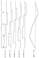
- FIG. 4 shows an example of control of the storage system group.
- the first storage system 40a to the fifth storage system 40e are included in the storage system group.
- the first power storage system 40a to the fifth power storage system 40e are controlled by the first power management system server 14a to the fifth power management system server 14e, respectively.
- the charge / discharge period is "0.5 seconds”
- the number of charge / discharge points is "5".
- Each power management system server 14 determines charge / discharge power "+2 kW" in "0.0" seconds. "+” Indicates discharge and "-" indicates charge.
- the first power storage system 40a performs "+2 kW” charge / discharge in “0.0" seconds
- the second power storage system 40 b performs “+2 kW” charge / discharge in “0.1” seconds
- the fifth power storage system 40e performs "+2 kW” charge and discharge in “0.4” seconds.
- each power management system server 14 determines the charge / discharge power “ ⁇ 1 kW” in “0.5” seconds.
- the first power storage system 40a performs "-1" kW charge / discharge in "0.5” seconds
- the second power storage system 40b performs “-1" kW charge / discharge in "0.6” seconds
- the fifth The storage system 40 e performs “ ⁇ 1 kW” charge / discharge in “0.9” seconds.
- the service linkage unit 300 of the first power management system server 14a is connected to the first group management system server 12a via the network 18, and executes communication with the first group management system server 12a.
- the receiving unit 510 receives a message from the first group management system server 12a.
- the message includes, for example, a table to be held in the storage unit 602.
- This table is generated in the first group management system server 12a, and is updated when the number of the plurality of power storage systems 40 managed by the first group management system server 12a changes.
- the group management system server 12 collectively manages a plurality of devices connected to each of the plurality of power management system servers 14.
- the table may be generated in the upper system server 10. In that case, it can be said that the receiving unit 510 receives a message including a table from the upper system server 10 via the first group management system server 12a.
- the message received by the receiving unit 510 may include information for specifying one of the adjustment power type A and the adjustment power type B to be used.
- the generation unit 604 uses the adjustment power type A or the adjustment power type B based on the designated information included in the message.
- the message received by the receiving unit 510 may include information on the number of charge and discharge points, and information on timing to be a starting point of the charge and discharge period.
- the transmission unit 512 transmits a message to the first group management system server 12a.
- the subject matter of the apparatus, system or method in the present disclosure comprises a computer.
- the computer executes the program to implement the functions of the apparatus, system, or method in the present disclosure.
- the computer includes, as a main hardware configuration, a processor that operates according to a program.
- the processor may be of any type as long as the function can be realized by executing a program.
- the processor is configured of one or more electronic circuits including a semiconductor integrated circuit (IC) or an LSI (Large Scale Integration).
- the plurality of electronic circuits may be integrated on one chip or may be provided on a plurality of chips.
- the plurality of chips may be integrated into one device or may be provided to a plurality of devices.
- the program is recorded in a non-transitory recording medium such as a computer readable ROM, an optical disc, a hard disk drive and the like.
- the program may be stored in advance in a recording medium, or may be supplied to the recording medium via a wide area communication network including the Internet and the like.
- FIG. 5 is a flowchart showing a control procedure by the first power management system server 14a.
- the frequency detection unit 600 detects the frequency of the power system 30 (S10).
- the generation unit 604 specifies charge / discharge power based on the detected frequency (S12).
- the generation unit 604 generates a random number (S14), and specifies the charge / discharge start time based on the random number during the charge / discharge period (S16).
- the transmitting unit 606 outputs an instruction including the charge and discharge power and the charge and discharge start time to the storage system 40 (S18).
- the frequency of the power system 30 is detected, and based on this, the power to be charged and discharged to the storage system 40 and the information on the time to start charging and discharging to the storage system 40 are generated. It is possible to control the rate of change of power according to the fluctuation of demand. Further, the difference between the frequency of power system 30 with respect to the reference frequency is detected, and based on this, the power to charge / discharge storage system 40 and information on the time to start charge / discharge to storage system 40 are generated. It is possible to control the rate of change of power according to the fluctuation of demand. Further, since the rate of change of the power is controlled according to the change of the power demand, it is possible to suppress the power system becoming unstable.
- the related information in which the power to be charged and discharged to the storage system 40 is associated with the frequency of the power system 30 or the difference in the frequency of the power system 30 with respect to the reference frequency is held, the process can be simplified. Further, since the related information in which the power to be charged and discharged to the storage system 40 is associated with the frequency of the power system 30 or the difference in the frequency of the power system 30 from the reference frequency is received, the related information can be updated. Further, since the related information is updated, even if the configuration of the VPP system 100 changes, the related information suitable for it can be used.
- one charge / discharge timing is specified by a random number generated with a predetermined probability, so the charge / discharge timings of the plurality of power storage systems 40 are uniformly distributed. It can be done.
- the outline of one aspect of the present disclosure is as follows.
- the power management system server 14 according to an aspect of the present disclosure is connected to a group management system server 12 that transmits a control command to a power storage system group including a power storage system 40 installed in each of a plurality of customers 16
- a power management system server 14 for controlling a power storage system 40 installed in a house 16, comprising: a frequency detection unit 600 for detecting a difference between the frequency of the power system 30 or the frequency of the power system 30 with respect to a reference frequency;
- the system includes the power for charging / discharging the storage system 40 based on the frequency or the difference detected at 600, and the generation unit 604 for generating information on the time for starting the charging / discharging of the storage system 40.
- the storage unit 602 may further include related information in which the power stored in the storage system 40 is associated with the frequency of the power system 30 or the difference in the frequency of the power system 30 with respect to the reference frequency.
- Generation unit 604 generates power to be charged / discharged to storage system 40 based on (1) the frequency or difference detected by frequency detection unit 600 and related information stored in storage unit 602, and (2) each During the period from when the storage system group starts charging / discharging to the target power of the storage system group to be achieved by charging / discharging the storage system 40, a time is generated to cause the storage system 40 to start charging / discharging.
- the generation unit 604 generates a time for causing the storage system 40 to start charging and discharging by specifying one timing with a random number generated with a predetermined probability among the plurality of timings defined during the period.
- Reception unit that receives related information that relates power to be charged / discharged to the storage system 40 with respect to the frequency of the power system 30 or the difference in frequency of the power system 30 with respect to the reference frequency from the upper system monitoring the power system 30 It further comprises 510.
- Another aspect of the present disclosure is a power control method.
- This method is connected to a group management system server 12 that transmits a control command to a storage system group including a storage system 40 installed in each of a plurality of customers 16 and also installed in the customer 16.
- a control method in the power management system server 14 for controlling the frequency of the power system 30 or the difference in the frequency of the power system 30 with respect to the reference frequency, and the storage system based on the detected frequency or the difference.
- Example 2 Next, Example 2 will be described.
- the present invention relates to a power management system that controls charging and discharging of a power storage system connected to a power system in accordance with an increase or decrease in power demand in the power system.
- the first embodiment even if the magnitude of the deviation between the frequency of the power system and the frequency of the commercial power source changes, the length of the charge / discharge period does not change.
- the second embodiment when the magnitude of the deviation between the frequency of the power system and the commercial power source frequency changes, the length of the charge and discharge period also changes.
- the configurations of the VPP system 100 and the customer 16 according to the second embodiment are the same as those shown in FIGS. 1 and 3. Here, differences from the first embodiment will be mainly described.
- the storage unit 602 in FIG. 2 holds related information in which the power to be charged / discharged to the storage system 40 and the charge / discharge period are associated with the frequency of the power system 30.
- the charge / discharge period is a period from when the storage system group starts charging / discharging to the target power of the storage system group to be achieved by charging / discharging of each storage system 40 until it reaches.
- the related information instead of the frequency of the power system 30, the difference of the frequency of the power system 30 with respect to the commercial power supply frequency may be used.
- the related information is held, for example, in the form of a table, but may be held in the form of a relational expression.
- FIG. 6 shows the data structure of a table stored in the storage unit 602. As illustrated, the relationship between the charge / discharge power and the charge / discharge period with respect to the detection frequency is shown. Here, it is assumed that the commercial power supply frequency is 60 Hz. The charge / discharge power is shown as in the first embodiment. In addition, as the absolute value of the difference between the frequency of power system 30 and the commercial power supply frequency increases, the charge and discharge period is extended. Return to FIG.
- the generation unit 604 extracts the charge and discharge power and the charge and discharge period by referring to the related information held in the storage unit 602 based on the frequency or the difference detected by the frequency detection unit 600. Further, as in the first embodiment, the generation unit 604 generates a random number to generate a charge / discharge start time that causes the storage system 40 to start charging / discharging during the charge / discharge period. The subsequent processing is the same as that described above, so the description is omitted here.
- the receiving unit 510 may receive a message including the table to be held in the storage unit 602 from the first group management system server 12a, as in the first embodiment.
- the charge / discharge period is changed according to the frequency of the power system 30 or the difference in frequency of the power system 30 with respect to the reference frequency, it is possible to adjust the speed of fluctuation of power.
- the related information in which the power to be charged / discharged to storage system 40 is associated with the charge / discharge period is held. You can In addition, the related information in which the power for charging / discharging the storage system 40 and the charging / discharging period are associated with the frequency of the power system 30 or the difference in the frequency of the power system 30 with respect to the reference frequency is received. It can be updated.
- one charge / discharge timing is specified by a random number generated with a predetermined probability, so the charge / discharge timings of the plurality of power storage systems 40 are uniformly distributed. It can be done.
- the outline of one aspect of the present disclosure is as follows. With respect to the frequency of the power system 30 or the difference in the frequency of the power system 30 with respect to the reference frequency, the power stored in the storage system 40 and the target power of the storage system group to be achieved by charging and discharging each storage system 40
- the system may further include a storage unit 602 that holds related information associated with a period from when the system group starts charging to discharging. (1) Based on the frequency or difference detected in the frequency detection unit 600 and the related information stored in the storage unit 602, the generation unit 604 generates power for charging and discharging the storage system 40 and a period ( 2) During the period, a time is generated to cause the storage system 40 to start charging and discharging.
- the power stored in the storage system 40 and the target power of the storage system group to be achieved by charging and discharging each storage system 40
- the system further includes a reception unit 510 that receives related information associated with a period from when the system group starts charging and discharging until it reaches from the upper system monitoring the power system 30.
- the frequency detection unit 600 to the transmission unit 606 are included in the first power management system server 14a.
- the frequency detection unit 600 to the transmission unit 606 may be included in the control device 216 of the storage system 40. In that case, it can be said that the control device 216 is a power control device. According to this modification, the degree of freedom of the configuration can be expanded.
- the number of charge and discharge timings is defined.
- fixed intervals may be defined.
- the fixed interval is fixed as 1/6 seconds. Therefore, since the charge / discharge timing is arranged at intervals of 1 ⁇ 6 second and the charge / discharge period ends in one second, the number of charge / discharge timings becomes “6”.
- each group becomes [0 to 0.166], [0.167 to 0.334],..., [0.835 to 1].
- 0.336 is generated as a random number, it is included in the third group. If the generated random number is 0.336, it belongs to the third group. Assuming that the charge / discharge timing of the first group is 14:15:00, the generation unit 604 determines the charge / discharge timing of 14: 15: 1/3 second. According to this modification, the degree of freedom of the configuration can be expanded.
Landscapes
- Engineering & Computer Science (AREA)
- Power Engineering (AREA)
- Supply And Distribution Of Alternating Current (AREA)
- Remote Monitoring And Control Of Power-Distribution Networks (AREA)
- Charge And Discharge Circuits For Batteries Or The Like (AREA)
Abstract
A power management system server 14 is connected to a group management system server 12 that transmits a control command to an electricity storage system group including an electricity storage system 40 installed at each of a plurality of consumers 16, and controls the electricity storage system 40 installed at a consumer 16. A frequency detection unit 600 detects the frequency of a power system 30 or the difference of the frequency of the power system 30 from a reference frequency. A generation unit 604, on the basis of the frequency or difference detected in the frequency detection unit 600, generates information about a power to be charged into or discharged from the electricity storage system 40, and a time at which the electricity storage system 40 is caused to start charging or discharging.
Description
本開示は、電力を制御する電力制御装置、電力制御方法、プログラムに関する。
The present disclosure relates to a power control apparatus that controls power, a power control method, and a program.
需要家に設置された機器を制御する制御装置を備える電力管理システムが提案されている。機器は、例えば、太陽電池、蓄電池、燃料電池等の分散電源、家電機器を含む。このような制御装置は、上位のスマートサーバに接続される。スマートサーバは、複数の需要家を統括的に管理する(例えば、特許文献1参照)。
There has been proposed a power management system provided with a control device that controls equipment installed at a customer. The apparatus includes, for example, a solar battery, a storage battery, a distributed power supply such as a fuel cell, and a home appliance. Such a control device is connected to the upper level smart server. The smart server centrally manages a plurality of consumers (see, for example, Patent Document 1).
需要家において電力系統に接続された蓄電システムを電力管理システムが制御するが、さらに複数の電力管理システムを群管理システムが制御する場合、電力需要の増減に応じて群管理システムは電力管理システム経由で各蓄電システムを充放電させる。しかしながら、複数の蓄電システムをまとめて充放電させると、電力の変動が大きくなって電力系統が不安定になる可能性がある。そのため、電力需要の変動に応じた電力の変動速度の制御が求められる。
The power management system controls the storage system connected to the power system in the customer, but when the group management system further controls a plurality of power management systems, the group management system goes through the power management system according to the increase or decrease of the power demand. Charge and discharge each storage system. However, if a plurality of power storage systems are charged and discharged together, power fluctuations may become large and the power system may become unstable. Therefore, control of the fluctuation speed of the power according to the fluctuation of the power demand is required.
本開示はこうした状況に鑑みなされたものであり、その目的は、電力需要の変動に応じて電力の変動速度を制御する技術を提供することにある。
The present disclosure has been made in view of such circumstances, and an object thereof is to provide a technique for controlling the rate of change of power according to the change in power demand.
上記課題を解決するために、本開示のある態様の電力制御装置は、複数の需要家の各々に設置された蓄電システムを含む蓄電システム群に制御指令を送信する群管理システムに接続されるとともに、需要家に設置された蓄電システムを制御する電力制御装置であって、電力系統の周波数、あるいは基準周波数に対する電力系統の周波数の差異を検出する周波数検出部と、周波数検出部において検出した周波数あるいは差異をもとに、蓄電システムに充放電させる電力と、蓄電システムに充放電を開始させる時刻に関する情報を生成する生成部と、を備える。
In order to solve the above problems, a power control apparatus according to an aspect of the present disclosure is connected to a group management system that transmits a control command to a storage system group including a storage system installed in each of a plurality of customers. A power control device for controlling a power storage system installed in a customer, the frequency detection unit detecting a difference between the frequency of the power system or the frequency of the power system with respect to the reference frequency, the frequency detected by the frequency detection unit Based on the difference, a power generation unit that charges and discharges the storage system and a generation unit that generates information related to the time at which the storage system starts charging and discharging is provided.
本開示の別の態様は、電力制御方法である。この方法は、複数の需要家の各々に設置された蓄電システムを含む蓄電システム群に制御指令を送信する群管理システムに接続されるとともに、需要家に設置された蓄電システムを制御する電力制御装置における制御方法であって、電力系統の周波数、あるいは基準周波数に対する電力系統の周波数の差異を検出するステップと、検出した周波数あるいは差異をもとに、蓄電システムに充放電させる電力と、蓄電システムに充放電を開始させる時刻に関する情報を生成するステップと、を備える。
Another aspect of the present disclosure is a power control method. This method is connected to a group management system for transmitting a control command to a storage system group including a storage system installed in each of a plurality of customers, and a power control apparatus for controlling the storage system installed in the customers. And detecting the difference between the frequency of the electric power system or the frequency of the electric power system with respect to the reference frequency, the electric power to be charged and discharged to the electric storage system based on the detected frequency or the difference, and Generating information regarding a time to start charging and discharging.
なお、以上の構成要素の任意の組合せ、本開示の表現を方法、装置、システム、コンピュータプログラム、またはコンピュータプログラムを記録した記録媒体などの間で変換したものもまた、本開示の態様として有効である。
It is to be noted that any combination of the above-described components, and the expression of the present disclosure converted between a method, an apparatus, a system, a computer program, or a recording medium having a computer program recorded thereon is also effective as an aspect of the present disclosure. is there.
本開示によれば、電力需要の変動に応じて電力の変動速度を制御できる。
According to the present disclosure, it is possible to control the rate of change of power according to the change in power demand.
(実施例1)
本開示の実施例を具体的に説明する前に、本実施例の概要を説明する。実施例は、電力系統における電力需要の増減に応じて、電力系統に接続された蓄電システムの充放電を制御する電力管理システムに関する。蓄電システムは、太陽光発電システム、燃料電池システム等の機器とともに各需要家に設置される。需要家は、電力会社等からの電力の供給を受けている施設であり、例えば、住宅、事務所、店舗、工場、公園などである。電力管理システムは、需要家における電力の消費量が大きい時間帯において蓄電システムを放電させたり、電力系統の電気料金が安価である夜間において蓄電システムを充電させたりする。ここでは、電力管理システムがVPP(Virtual Power Plant)に含まれることを想定する。VPPは、点在する小規模な太陽光発電システム、蓄電システム、燃料電池システム等の機器と、電力の需要抑制を統合して制御する。VPPは、太陽光発電システム、蓄電システム、燃料電池システム等の機器をネットワークを介して制御することによって、これらを1つの発電所のようにまとめて機能させる。 Example 1
Before specifically describing the embodiments of the present disclosure, an outline of the present embodiment will be described. An embodiment relates to a power management system that controls charging and discharging of a storage system connected to a power system according to an increase or decrease in power demand in the power system. The storage system is installed in each customer along with devices such as a solar power generation system and a fuel cell system. The customer is a facility receiving power supply from a power company or the like, and is, for example, a house, an office, a store, a factory, a park, or the like. The power management system discharges the storage system in a time zone in which the consumer consumes a large amount of power, or charges the storage system at night when the electricity bill of the power system is inexpensive. Here, it is assumed that the power management system is included in a VPP (Virtual Power Plant). VPP integrates and controls equipment such as small-scale solar power generation systems, power storage systems, fuel cell systems, etc., which are scattered, with power demand suppression. The VPP controls devices such as a photovoltaic power generation system, a storage system, and a fuel cell system via a network to make them function as a single power plant.
このようなVPPを実現するために、複数の電力管理システムは、群管理システムに接続される。また、群管理システムは、複数の群管理システムを統合するアグリゲータである上位システムに接続される。上位システムと群管理システムに、需要家に設置された蓄電システム等の機器を加えたものがVPPに相当する。上位システムは、市場で、あるいは事業者と相対契約で電力を取引する。また、上位システムは、電力取引市場や電力会社の送配電部門、小売電気事業者等に集約した調整力を提供する。そのため、上位システムは、市場あるいは各事業者に提供する調整力を決定し、調整力を各群管理システムに配分する。各群管理システムは、さらに調整力を各需要家に配分する。これより、群管理システムは、上位システムからの要求に応じて売電あるいは買電するように、複数の電力管理システムのそれぞれに対して制御を指示する。例えば、群管理システムは、発電所において発電される電力が逼迫する場合、蓄電システムを放電させたり、需要家における電力消費を抑制させたりするように制御することを電力管理システムに要求する。
In order to realize such VPP, multiple power management systems are connected to a group management system. In addition, the group management system is connected to a host system which is an aggregator that integrates a plurality of group management systems. A VPP is equivalent to the upper system and the group management system plus equipment such as a storage system installed in the customer. The higher-level system trades power in the market or in a relative contract with the business operator. In addition, the higher-level system provides integrated coordination power to the power exchange market, the power transmission and distribution department of the power company, the retail power company, and the like. Therefore, the higher-level system determines the coordination power to be provided to the market or each business operator, and distributes the coordination power to each group management system. Each group management system further distributes coordination to each customer. Thus, the group management system instructs each of the plurality of power management systems to control to sell or buy power in response to a request from the upper system. For example, the group management system requests the power management system to control the storage system to be discharged or to reduce the power consumption of the customer when the power generated by the power plant becomes tight.
群管理システムに複数の電力管理システムが接続され、各電力管理システムに1つ以上の蓄電システムが接続されることによって、これらは階層的に配置されている。そのため、複数の蓄電システム(以下、「蓄電システム群」ともいう)による電力の変動を群管理システムが制御するといえる。一方、電力系統における電力需要の変動は、変動周期が互いに異なった微少変動分、短周期成分、長周期成分の合成によって示される。これらの合成の割合は状況に応じて異なり、例えば、電力需要は変動しながら増加する。電力需要の増減に応じて、群管理システムが複数の蓄電システムを一斉に充放電させると、電力の変動が大きくなり電力系統が不安定となる。そのため、電力需要の増減の速度に応じて、電力の変動速度も調節されることが望ましい。
A plurality of power management systems are connected to the group management system, and one or more power storage systems are connected to each power management system, which are arranged hierarchically. Therefore, it can be said that the group management system controls fluctuations in power due to a plurality of power storage systems (hereinafter also referred to as "power storage system group"). On the other hand, the fluctuation of the power demand in the electric power system is indicated by the combination of a minute fluctuation, a short cycle component and a long cycle component in which fluctuation cycles are mutually different. The proportions of these combinations vary depending on the situation, for example, the power demand fluctuates and increases. When the group management system charges and discharges a plurality of power storage systems simultaneously in response to the increase and decrease of the power demand, the fluctuation of the power becomes large and the power system becomes unstable. Therefore, it is desirable that the rate of change of the power be adjusted according to the rate of increase or decrease of the power demand.
このような状況に対応するために、本実施例における各電力管理システムは、時間の経過とともに充放電している蓄電システムの数が変わるように、充放電の充放電開始時刻を決定するとともに、検出した電力系統の周波数をもとに充放電電力を調節する。各電力管理システムは、充放電の充放電開始時刻が到来した場合に、充放電電力の充放電を蓄電システムに実行させる。各電力管理システムにおいて独立した制御がなされるが、各電力管理システムにおいて検出される電力系統の周波数は共通であり、かつ上位システムあるいは群管理サーバにおいて生成されたテーブルを使用する。そのため、各電力管理システムにおける制御は共通になる。
In order to cope with such a situation, each power management system in this embodiment determines the charge / discharge start time of charge / discharge so that the number of charge / discharge power storage systems changes with the passage of time, Charge / discharge power is adjusted based on the detected power system frequency. Each power management system causes the storage system to execute charge / discharge of charge / discharge power when charge / discharge start time of charge / discharge comes. Although independent control is performed in each power management system, the power system frequency detected in each power management system is common, and uses a table generated in the upper system or the group management server. Therefore, control in each power management system is common.
図1は、VPPシステム100の構成を示す。VPPシステム100は、上位システムサーバ10、群管理システムサーバ12と総称される第1群管理システムサーバ12a、第2群管理システムサーバ12b、第M群管理システムサーバ12m、電力管理システムサーバ14と総称される第1電力管理システムサーバ14a、第2電力管理システムサーバ14b、第N電力管理システムサーバ14nを含む。ここで、第1電力管理システムサーバ14aは第1需要家16aに設置され、第2電力管理システムサーバ14bは第2需要家16bに設置され、第N電力管理システムサーバ14nは第N需要家16nに設置され、第1需要家16a、第2需要家16b、第N需要家16nは需要家16と総称される。群管理システムサーバ12の数は「M」に限定されず、電力管理システムサーバ14と需要家16の数は「N」に限定されない。
FIG. 1 shows the configuration of the VPP system 100. The VPP system 100 includes a host system server 10 and a group management system server 12 collectively referred to as a first group management system server 12a, a second group management system server 12b, an Mth group management system server 12m and a power management system server 14 generically. First power management system server 14a, a second power management system server 14b, and an Nth power management system server 14n. Here, the first power management system server 14a is installed in the first customer 16a, the second power management system server 14b is installed in the second customer 16b, and the Nth power management system server 14n is the Nth customer 16n. The first customer 16a, the second customer 16b, and the N-th customer 16n are collectively referred to as the customer 16. The number of group management system servers 12 is not limited to "M", and the number of power management system servers 14 and customers 16 is not limited to "N".
需要家16は、例えば、一戸建ての住宅、マンションなどの集合住宅、コンビニエンスストアまたはスーパーマーケットなどの店舗、ビルなどの商用施設、工場であり、前述のごとく、電力会社等からの電力の供給を受けている施設である。需要家16には、空調機器(エアコン)、テレビジョン受信装置(テレビ)、照明装置、蓄電システム、ヒートポンプ給湯機等の機器が設置される。これらの機器は、電力事業者等の電力系統に接続されることによって、商用電力の供給を受けて、電力を消費する。機器として、電力使用の削減量が比較的大きいと想定されるものが有用であるが、削減量があまり大きくないと想定されてもよい。機器に、太陽電池システム、燃料電池システム等の再生可能エネルギー発電装置が含まれてもよい。
The customer 16 is, for example, a single-family house, an apartment house such as an apartment, a store such as a convenience store or a supermarket, a commercial facility such as a building, a factory. It is an existing facility. The customer 16 is provided with equipment such as an air conditioner (air conditioner), a television receiver (television), a lighting device, a storage system, and a heat pump water heater. These devices receive the supply of commercial power and consume power by being connected to a power system such as a power company. As an apparatus, although what is assumed that the reduction amount of electric power consumption is comparatively large is useful, it may be assumed that the reduction amount is not so large. The device may include a renewable energy generator such as a solar cell system or a fuel cell system.
電力管理システムサーバ14は、電力管理システムの処理を実行するためのコンピュータであり、例えば、需要家16内に設置される。電力管理システムサーバ14は、例えば、HEMS(Home Energy Management System)コントローラとしての機能を有する。そのため、電力管理システムサーバ14は、HAN(Home Area Network)により需要家16内の各種機器と通信可能であり、これらの機器を制御する。電力管理システムサーバ14は、蓄電システムの動作、例えば、放電、充電を制御する。また、電力管理システムサーバ14は、需要家16に設置された機器と電力系統との間の連系を制御してもよい。電力管理システムサーバ14は、停電時に機器と電力系統との間を解列し、復電時に機器と電力系統との間を連系する。
The power management system server 14 is a computer for executing the processing of the power management system, and is installed, for example, in the customer 16. The power management system server 14 has, for example, a function as a home energy management system (HEMS) controller. Therefore, the power management system server 14 can communicate with various devices in the customer 16 by HAN (Home Area Network), and controls these devices. The power management system server 14 controls the operation of the storage system, for example, discharge and charge. In addition, the power management system server 14 may control the interconnection between the devices installed in the customer 16 and the power system. The power management system server 14 disconnects between the device and the power system at the time of power failure, and interconnects between the device and the power system at the time of power recovery.
群管理システムサーバ12は、群管理システムの処理を実行するためのコンピュータである。群管理システムサーバ12は、複数の電力管理システムサーバ14を接続することによって、複数の電力管理システムサーバ14を管理する。その結果、群管理システムサーバ12は、複数の電力管理システムサーバ14のそれぞれに接続される複数の機器を統括的に管理する。例えば、群管理システムサーバ12は、複数の需要家16の各々に設置された蓄電システムを含む蓄電システム群に制御指令を送信してもよい。複数の群管理システムサーバ12は、上位システムサーバ10に接続される。上位システムサーバ10は、アグリゲータである上位システムの処理を実行するためのコンピュータである。前述のごとく、上位システムと群管理システムを含むVPPは、市場で、あるいは事業者と相対契約で電力を取引しており、上位システムサーバ10は、契約に応じた要求を群管理システムサーバ12に出力する。1つの群管理システムサーバ12が複数の上位システムサーバ10に接続されてもよい。
The group management system server 12 is a computer for executing the processing of the group management system. The group management system server 12 manages a plurality of power management system servers 14 by connecting a plurality of power management system servers 14. As a result, the group management system server 12 centrally manages a plurality of devices connected to each of the plurality of power management system servers 14. For example, the group management system server 12 may transmit a control command to a storage system group including a storage system installed in each of the plurality of customers 16. The plurality of group management system servers 12 are connected to the upper system server 10. The upper system server 10 is a computer for executing the processing of the upper system which is an aggregator. As described above, the VPP including the upper system and the group management system trades power in the market or in a relative contract with the business operator, and the upper system server 10 sends the group management system server 12 a request according to the contract. Output. One group management system server 12 may be connected to a plurality of upper system servers 10.
このような構成によって、電力系統における電力需要が逼迫する場合、群管理システムサーバ12は、蓄電システムから放電した電力を需要家16内で消費させたり、需要家16内での電力消費を抑制させたりするように電力管理システムサーバ14を制御する。また、電力系統における電力供給が電力需要を上まわる場合、群管理システムサーバ12は、蓄電システムへの充電を増やしたり、需要家16内での需要を増大させたりするように電力管理システムサーバ14を制御する。
With such a configuration, when the power demand in the power system is tight, the group management system server 12 causes the power discharged from the storage system to be consumed in the customer 16 or suppresses the power consumption in the customer 16. Control the power management system server 14 to In addition, when the power supply in the power system exceeds the power demand, the group management system server 12 increases the charge to the storage system or increases the demand in the customer 16. Control.
図2は、需要家16の構成を示す。需要家16には、電力系統30、スマートメータ32、分電盤34、負荷36、蓄電システム40、電力管理システムサーバ14、例えば第1電力管理システムサーバ14aが設置される。また、蓄電システム40は、SB(Storage Battery)210、SB用DC/DC212、双方向DC/ACインバータ214、制御装置216を含む。第1電力管理システムサーバ14aは、サービス連携部300、制御部302を含み、サービス連携部300は、受信部510、送信部512を含み、制御部302は、周波数検出部600、記憶部602、生成部604、送信部606、受信部608を含む。さらに、第1電力管理システムサーバ14aには、ネットワーク18を介して群管理システムサーバ12、例えば第1群管理システムサーバ12aが接続される。需要家16には、太陽電池システム、ヒートポンプ給湯機等が設置されてもよいが、ここではこれらを省略する。
FIG. 2 shows the configuration of the customer 16. The customer 16 is provided with a power system 30, a smart meter 32, a distribution board 34, a load 36, a storage system 40, and a power management system server 14, for example, a first power management system server 14a. Further, the storage system 40 includes a storage battery (SB) 210, a DC / DC 212 for SB, a bi-directional DC / AC inverter 214, and a control device 216. The first power management system server 14a includes a service cooperation unit 300 and a control unit 302. The service cooperation unit 300 includes a reception unit 510 and a transmission unit 512. The control unit 302 includes a frequency detection unit 600, a storage unit 602, A generation unit 604, a transmission unit 606, and a reception unit 608 are included. Furthermore, a group management system server 12, for example, a first group management system server 12a is connected to the first power management system server 14a via the network 18. Although a solar cell system, a heat pump water heater, etc. may be installed in the customer 16, these are omitted here.
電力系統30における電力需要は、変動周期が互いに異なった微少変動分、短周期成分、長周期成分の合成によって示される。微少変動分は数十秒程度の変動周期を有し、短周期成分は数分程度の変動周期を有し、長周期成分は数十分程度の変動周期を有する。つまり、微少変動分の変動周期が最も短く、長周期成分の変動周期が最も長い。スマートメータ32は、電力系統30に接続され、デジタル式の電力量計である。スマートメータ32は、電力系統30から入ってくる潮流の電力量と、電力系統30へ出て行く逆潮流の電力量とを計測可能である。スマートメータ32は、通信機能を有し、電力管理システムサーバ14と通信可能である。
The power demand in the power system 30 is indicated by the combination of a minute variation, a short period component, and a long period component, which have different variation cycles. The minute change component has a change period of about several tens of seconds, the short period component has a change period of about several minutes, and the long period component has a change period of about several tens of minutes. That is, the variation period of the minute variation is the shortest, and the variation period of the long period component is the longest. The smart meter 32 is connected to the power system 30 and is a digital power meter. The smart meter 32 can measure the amount of power of the current flowing from the power system 30 and the amount of power of the reverse current flowing out of the power system 30. The smart meter 32 has a communication function and can communicate with the power management system server 14.
配電線42は、スマートメータ32と分電盤34とを結ぶ。分電盤34は、配電線42に接続されるとともに、負荷36を接続する。分電盤34は、負荷36に電力を供給する。負荷36は、配電線42を介して供給される電力を消費する機器である。負荷36は、冷蔵庫、エアコン、照明等の機器を含む。ここでは、分電盤34に1つの負荷36が接続されているが、分電盤34に複数の負荷36が接続されてもよい。
The distribution line 42 connects the smart meter 32 and the distribution board 34. The distribution board 34 is connected to the distribution line 42 and also connects the load 36. The distribution board 34 supplies power to the load 36. The load 36 is a device that consumes the power supplied via the distribution line 42. The load 36 includes equipment such as a refrigerator, an air conditioner, and lighting. Here, although one load 36 is connected to the distribution board 34, a plurality of loads 36 may be connected to the distribution board 34.
SB210は、電力を充放電可能な蓄電池であり、リチウムイオン蓄電池、ニッケル水素蓄電池、鉛蓄電池、電気二重層キャパシタ、リチウムイオンキャパシタ等を含む。SB210はSB用DC/DC212に接続される。SB用DC/DC212は、DC-DCコンバータであり、SB210側の直流電力と、双方向DC/ACインバータ214側の直流電力との間の変換を実行する。
The SB 210 is a storage battery capable of charging and discharging electric power, and includes a lithium ion storage battery, a nickel hydrogen storage battery, a lead storage battery, an electric double layer capacitor, a lithium ion capacitor, and the like. The SB 210 is connected to the DC / DC 212 for SB. The SB DC / DC 212 is a DC-DC converter, and performs conversion between the DC power on the SB 210 side and the DC power on the bidirectional DC / AC inverter 214 side.
双方向DC/ACインバータ214は、SB用DC/DC212と分電盤34との間に接続される。双方向DC/ACインバータ214は、分電盤34からの交流電力を直流電力に変換し、変換した直流電力をSB用DC/DC212に出力する。また、双方向DC/ACインバータ214は、SB用DC/DC212からの直流電力を交流電力に変換し、変換した交流電力を分電盤34に出力する。つまり、双方向DC/ACインバータ214によってSB210は充放電される。このような双方向DC/ACインバータ214の制御は制御装置216によってなされる。ここで、SB210、SB用DC/DC212、双方向DC/ACインバータ214、制御装置216は1つの筐体に格納されてもよく、その場合であっても、これを蓄電システム40と呼ぶ。
The bi-directional DC / AC inverter 214 is connected between the DC / DC 212 for SB and the distribution board 34. The bidirectional DC / AC inverter 214 converts AC power from the distribution board 34 into DC power, and outputs the converted DC power to the SB DC / DC 212. The bidirectional DC / AC inverter 214 converts the DC power from the SB DC / DC 212 into AC power, and outputs the converted AC power to the distribution board 34. That is, the SB 210 is charged and discharged by the bi-directional DC / AC inverter 214. The control of the bi-directional DC / AC inverter 214 is performed by the controller 216. Here, the SB 210, the SB DC / DC 212, the bidirectional DC / AC inverter 214, and the control device 216 may be stored in one case, and even in that case, this is referred to as a storage system 40.
第1電力管理システムサーバ14aは、HAN等のネットワークを介して、スマートメータ32、蓄電システム40に接続され、それぞれと通信可能であり、電力系統30に接続された蓄電システム40を制御する。このような第1電力管理システムサーバ14aは電力制御装置であるといえる。以下では、第1電力管理システムサーバ14aとスマートメータ32との間の通信は説明を省略する。
The first power management system server 14 a is connected to the smart meter 32 and the storage system 40 via a network such as HAN, can communicate with each other, and controls the storage system 40 connected to the power system 30. It can be said that such a first power management system server 14a is a power control device. In the following, the communication between the first power management system server 14a and the smart meter 32 will not be described.
周波数検出部600は、電力系統30に接続される。周波数検出部600は、電力系統30における交流電力の周波数(以下、「電力系統30の周波数」ともいう)を検出する。電力系統30の周波数は、電力需要が増加して電力が不足すると商用電源周波数より低くなり、電力需要が減少して電力が過剰になると商用電源周波数より高くなる。商用電源周波数は、例えば、50Hz、60Hzに定められる基準周波数である。周波数検出部600は、商用電源周波数に対する電力系統30の周波数の差異を検出してもよい。周波数検出部600は、スマートメータ32あるいは配電線42に接続されて、電力系統30の周波数を検出してもよい。さらに、周波数検出部600は蓄電システム40内に設けられ、検出した周波数を第1電力管理システムサーバ14aに送信してもよい。
The frequency detection unit 600 is connected to the power system 30. Frequency detection unit 600 detects the frequency of AC power in power system 30 (hereinafter, also referred to as “frequency of power system 30”). The frequency of the power system 30 becomes lower than the commercial power frequency when the power demand increases and runs short of power, and becomes higher than the commercial power frequency when the power demand decreases and the power becomes excessive. The commercial power supply frequency is, for example, a reference frequency defined at 50 Hz and 60 Hz. The frequency detection unit 600 may detect the difference in frequency of the power system 30 with respect to the commercial power supply frequency. The frequency detection unit 600 may be connected to the smart meter 32 or the distribution line 42 to detect the frequency of the power system 30. Furthermore, the frequency detection unit 600 may be provided in the storage system 40, and may transmit the detected frequency to the first power management system server 14a.
記憶部602は、電力系統30の周波数に対して、蓄電システム40に充放電させる電力を関連づけた関連情報を保持する。関連情報では、電力系統30の周波数の代わりに、商用電源周波数に対する電力系統30の周波数の差異が使用されてもよい。関連情報は例えばテーブルの形式で保持されるが、関係式の形式で保持されてもよい。図3は、記憶部602に記憶されるテーブルのデータ構造を示す。図示のごとく、検出周波数に対する充放電電力の関連が示される。ここでは、商用電源周波数が60Hzであるとされる。検出周波数が60Hzよりも高い場合、つまり電力系統30の周波数が商用電源周波数よりも高い場合、蓄電システム40に充電を実行させるような充放電電力が規定される。一方、検出周波数が60Hzよりも低い場合、つまり電力系統30における交流電力の周波数が商用電源周波数よりも低い場合、蓄電システム40に放電を実行させるような充放電電力が規定される。ここで、電力系統30の周波数と商用電源周波数との差異の絶対値が大きくなるほど、充放電電力の絶対値は大きくなるが、その理由については後述する。図2に戻る。
Storage unit 602 holds related information in which the power to be charged / discharged to / from storage system 40 is associated with the frequency of power system 30. In the related information, instead of the frequency of the power system 30, the difference of the frequency of the power system 30 with respect to the commercial power supply frequency may be used. The related information is held, for example, in the form of a table, but may be held in the form of a relational expression. FIG. 3 shows the data structure of a table stored in the storage unit 602. As shown, the relationship of charge and discharge power to the detection frequency is shown. Here, it is assumed that the commercial power supply frequency is 60 Hz. When the detection frequency is higher than 60 Hz, that is, when the frequency of the power system 30 is higher than the commercial power supply frequency, charge / discharge power is defined that causes the storage system 40 to perform charging. On the other hand, when the detection frequency is lower than 60 Hz, that is, when the frequency of AC power in power system 30 is lower than the commercial power source frequency, charge / discharge power is defined that causes storage system 40 to perform discharge. Here, the absolute value of charge / discharge power increases as the absolute value of the difference between the frequency of power system 30 and the commercial power source frequency increases, but the reason will be described later. Return to FIG.
生成部604は、周波数検出部600において検出した周波数または差異をもとに、記憶部602において保持したテーブルを参照することによって、蓄電システム40に充放電させる電力と、蓄電システム40に充放電を開始させる時刻(以下、「充放電開始時刻」ともいう)に関する情報を生成する。周波数検出部600において検出された電力系統30の周波数が商用電源周波数よりも低い場合であっても、これらの周波数のずれの大きさに応じて、電力不足の程度が異なる。例えば、これらの周波数のずれが大きい場合は、これらの周波数のずれが小さい場合よりも、電力不足の程度が大きいといえる。つまり、これらの周波数のずれが大きい場合には、これらの周波数のずれが小さい場合よりも、充放電電力の絶対値を大きくするとともに、蓄電システム群による電力の変動速度を速くしなければならない。そのため、前述のごとく、電力系統30の周波数と商用電源周波数との差異の絶対値が大きくなるほど、充放電電力の絶対値が大きくなるような規定がなされる。生成部604は、周波数検出部600において検出した周波数あるいは差異をもとに、記憶部602において保持した関連情報を参照することによって、蓄電システム40に充放電させる充放電電力を抽出する。
The generation unit 604 refers to the table held in the storage unit 602 based on the frequency or difference detected by the frequency detection unit 600 to charge / discharge the power of the storage system 40 and charge / discharge the storage system 40. Information on the time to be started (hereinafter also referred to as “charge / discharge start time”) is generated. Even when the frequency of the power system 30 detected by the frequency detection unit 600 is lower than the commercial power supply frequency, the degree of the power shortage differs according to the magnitude of the deviation of these frequencies. For example, when the deviation of these frequencies is large, it can be said that the degree of the power shortage is larger than when the deviation of these frequencies is small. That is, when these frequency deviations are large, it is necessary to increase the absolute value of the charge / discharge power and to increase the rate of change of the power of the storage system group more than when the frequency deviations are small. Therefore, as described above, it is defined that the absolute value of charge / discharge power increases as the absolute value of the difference between the frequency of power system 30 and the commercial power source frequency increases. Based on the frequency or difference detected by frequency detection unit 600, generation unit 604 extracts charge / discharge power to be charged / discharged by storage system 40 by referring to the related information stored in storage unit 602.
また、電力の変動速度を調節するために、蓄電システム群において充放電を実行する蓄電システム40の数が調節される。具体的には、時間の経過とともに充放電している蓄電システム40の数を増加させることによって、時間の経過とともに充放電の電力を増加させることが可能になる。例えば、所定の充放電開始時刻において10台の蓄電システム40に放電させ、一定の間隔が経過した後に追加の10台の蓄電システム40に放電させ、さらに一定の間隔が経過した後に追加の10台の蓄電システム40に放電させることによって、放電される電力が増加する。つまり、各蓄電システム40が順に充放電を開始することによって、一定期間(以下、「充放電期間」という)経過後に、蓄電システム群が目標電力に達成することになる。さらに、一定間隔でほぼ同一数の蓄電システム40が順に放電を開始する場合であっても、1台の蓄電システム40の放電電力が大きくなれば、電力の変動速度が速くなる。充電がなされる場合も放電がなされる場合と同様である。
Further, in order to adjust the change speed of the power, the number of power storage systems 40 performing charging and discharging in the power storage system group is adjusted. Specifically, by increasing the number of power storage systems 40 being charged and discharged with the passage of time, it becomes possible to increase the power of charging and discharging with the passage of time. For example, 10 storage systems 40 are discharged at a predetermined charge / discharge start time, and an additional 10 storage systems 40 are discharged after a predetermined interval elapses, and an additional 10 storage systems after a predetermined interval elapses By discharging the storage system 40 of the above, the power to be discharged is increased. That is, when each storage system 40 starts charging and discharging in order, the storage system group achieves the target power after a predetermined period (hereinafter, referred to as “charging and discharging period”) has elapsed. Furthermore, even in the case where approximately the same number of storage systems 40 start discharging in order at regular intervals, if the discharge power of one storage system 40 increases, the speed of change of the power increases. The case of charging is similar to the case of discharging.
このような処理を実現するために、一定間隔でほぼ同一数の蓄電システム40を充放電を開始させる必要がある。特に、充放電の開始は自律的になされるべきである。ここでは、蓄電システム群が充放電を開始してから、蓄電システム群が目標電力に到達するまでの充放電期間は、固定値であるとする。また、充放電期間中には、複数の充放電タイミングが一定間隔で配置される。充放電タイミングの数も固定値であるとする。これは、一定間隔も固定値であることに相当する。そのため、充放電期間の起点となるタイミング、充放電期間、充放電タイミングの数は、予め定められているとする。
In order to realize such processing, it is necessary to start charging / discharging approximately the same number of storage systems 40 at regular intervals. In particular, initiation of charging and discharging should be done autonomously. Here, after the storage system group starts charging and discharging, the charging and discharging period until the storage system group reaches the target power is assumed to be a fixed value. Further, during the charge and discharge period, a plurality of charge and discharge timings are arranged at regular intervals. The number of charge / discharge timings is also assumed to be a fixed value. This corresponds to the fact that the fixed interval is also a fixed value. Therefore, it is assumed that the timing which becomes the starting point of the charge and discharge period, the charge and discharge period, and the number of charge and discharge timings are determined in advance.
生成部604は、乱数、例えば疑似乱数を生成する。乱数の生成には公知の技術が使用されればよいので、ここでは説明を省略する。複数の電力管理システムサーバ14における生成部604は、共通方法で乱数を生成する。生成部604は、充放電期間中に規定した複数の充放電タイミングのうち、所定の確率で発生させた乱数により1つの充放電タイミングを特定することによって、蓄電システム40に充放電を開始させる充放電開始時刻を生成する。
The generation unit 604 generates a random number, for example, a pseudo random number. A well-known technique may be used to generate the random number, so the description is omitted here. The generation unit 604 in the plurality of power management system servers 14 generates a random number by a common method. Among the plurality of charge / discharge timings defined during the charge / discharge period, generation unit 604 specifies charge / discharge timing by using random numbers generated with a predetermined probability, thereby causing charge / discharge of storage system 40 to start charging. Generate discharge start time.
充放電期間が1秒であり、充放電タイミングの数が「10」である場合、一定間隔は0.1秒である。生成部604は、0から1の間の値を乱数で生成する。また、0から1の間は、[0~0.1]、[0.1~0.2]、・・・・、[0.9~1]の10個のグループに区分されるとともに、グループと充放電タイミングとが1対1で対応づけられる。そのため、1つ目のグループが1つ目の充放電タイミングで充放電を開始し、2つ目のグループが2つ目の充放電タイミングで充放電を開始する。生成された乱数が0.28である場合、これは3つ目のグループ[0.2~0.3]に属する。1つ目のグループの充放電タイミングが14時15分0秒であるとすれば、生成部604は、14時15分0.2秒の充放電タイミングを決定する。具体的に時刻が定められた充放電タイミングが「充放電開始時刻」に相当する。
When the charge / discharge period is 1 second and the number of charge / discharge timings is "10", the fixed interval is 0.1 second. The generation unit 604 generates a value between 0 and 1 as a random number. Moreover, while being divided into ten groups of [0 to 0.1], [0.1 to 0.2], ..., [0.9 to 1] between 0 and 1, Groups and charge / discharge timings are associated on a one-to-one basis. Therefore, the first group starts charging and discharging at the first charging and discharging timing, and the second group starts charging and discharging at the second charging and discharging timing. If the generated random number is 0.28, it belongs to the third group [0.2 to 0.3]. Assuming that the charge / discharge timing of the first group is 14:15:00, the generation unit 604 determines the charge / discharge timing of 14: 15: 0.2. The charge / discharge timing at which the time is specifically determined corresponds to the “charge / discharge start time”.
充放電期間が複数の種類規定されていてもよい。例えば、「1秒」の調整力種別Aと「0.5秒」の調整力種別Bのごとく、長さの異なった2種類の充放電期間が規定される。その際、調整力種別Aと調整力種別Bのどちらを使用するかは、生成部604に予め設定されている。生成部604は、生成した情報を送信部606に出力する。送信部606は、生成した情報が含まれたメッセージを蓄電システム40に出力する。
A plurality of charge and discharge periods may be defined. For example, two types of charge / discharge periods having different lengths are defined, such as an adjustment power type A of “1 second” and an adjustment power type B of “0.5 second”. At this time, which of the adjustment power type A and the adjustment power type B is used is set in the generation unit 604 in advance. The generation unit 604 outputs the generated information to the transmission unit 606. Transmission unit 606 outputs a message including the generated information to power storage system 40.
蓄電システム40における制御装置216は、第1電力管理システムサーバ14aからのメッセージに応じて、充放電開始時刻において充放電電力を充電あるいは放電する。制御装置216は、メッセージにしたがった充電あるは放電を実行した場合、完了が示されたメッセージを第1電力管理システムサーバ14aに送信してもよい。このメッセージは、第1電力管理システムサーバ14aの制御部302における受信部608に受信される。
The control device 216 in the storage system 40 charges or discharges the charge / discharge power at the charge / discharge start time in accordance with the message from the first power management system server 14 a. The controller 216 may transmit a message indicating completion to the first power management system server 14a when performing charging or discharging according to the message. This message is received by the receiver 608 in the controller 302 of the first power management system server 14a.
図4は、蓄電システム群の制御例を示す。ここでは、蓄電システム群に第1蓄電システム40aから第5蓄電システム40eが含まれているとする。また、第1蓄電システム40aから第5蓄電システム40eは、第1電力管理システムサーバ14aから第5電力管理システムサーバ14eのそれぞれに制御されているとする。ここで、充放電期間は「0.5秒」であり、充放電ポイントの数は「5」であるとされる。各電力管理システムサーバ14は、「0.0」秒において充放電電力「+2kW」を決定する。「+」が放電を示し、「-」が充電を示す。第1蓄電システム40aは「0.0」秒で「+2kW」の充放電を実行し、第2蓄電システム40bは「0.1」秒で「+2kW」の充放電を実行し、第5蓄電システム40eは「0.4」秒で「+2kW」の充放電を実行する。続いて、各電力管理システムサーバ14は、「0.5」秒で充放電電力「-1kW」を決定する。第1蓄電システム40aは「0.5」秒で「-1kW」の充放電を実行し、第2蓄電システム40bは「0.6」秒で「-1kW」の充放電を実行し、第5蓄電システム40eは「0.9」秒で「-1kW」の充放電を実行する。第1蓄電システム40aから第5蓄電システム40eによる充放電を合成することによって、蓄電システム群による充放電が実現される。図2に戻る。
FIG. 4 shows an example of control of the storage system group. Here, it is assumed that the first storage system 40a to the fifth storage system 40e are included in the storage system group. Also, it is assumed that the first power storage system 40a to the fifth power storage system 40e are controlled by the first power management system server 14a to the fifth power management system server 14e, respectively. Here, the charge / discharge period is "0.5 seconds", and the number of charge / discharge points is "5". Each power management system server 14 determines charge / discharge power "+2 kW" in "0.0" seconds. "+" Indicates discharge and "-" indicates charge. The first power storage system 40a performs "+2 kW" charge / discharge in "0.0" seconds, and the second power storage system 40 b performs "+2 kW" charge / discharge in "0.1" seconds, and the fifth power storage system 40e performs "+2 kW" charge and discharge in "0.4" seconds. Subsequently, each power management system server 14 determines the charge / discharge power “−1 kW” in “0.5” seconds. The first power storage system 40a performs "-1" kW charge / discharge in "0.5" seconds, and the second power storage system 40b performs "-1" kW charge / discharge in "0.6" seconds, the fifth The storage system 40 e performs “−1 kW” charge / discharge in “0.9” seconds. By combining the charge and discharge by the first power storage system 40a to the fifth power storage system 40e, the charge and discharge by the power storage system group is realized. Return to FIG.
第1電力管理システムサーバ14aのサービス連携部300は、ネットワーク18を介して第1群管理システムサーバ12aに接続され、第1群管理システムサーバ12aとの間で通信を実行する。受信部510は、第1群管理システムサーバ12aからのメッセージを受信する。メッセージには、例えば、記憶部602において保持すべきテーブルが含まれる。このテーブルは、第1群管理システムサーバ12aにおいて生成されており、第1群管理システムサーバ12aによって管理される複数の蓄電システム40の数が変わった場合に更新される。このように各電力管理システムサーバ14において共通のテーブルが使用されるので、群管理システムサーバ12は、複数の電力管理システムサーバ14のそれぞれに接続される複数の機器を統括的に管理するといえる。テーブルは上位システムサーバ10において生成されてもよい。その場合、受信部510は、第1群管理システムサーバ12a経由で上位システムサーバ10から、テーブルが含まれたメッセージを受信するといえる。
The service linkage unit 300 of the first power management system server 14a is connected to the first group management system server 12a via the network 18, and executes communication with the first group management system server 12a. The receiving unit 510 receives a message from the first group management system server 12a. The message includes, for example, a table to be held in the storage unit 602. This table is generated in the first group management system server 12a, and is updated when the number of the plurality of power storage systems 40 managed by the first group management system server 12a changes. As described above, since the common table is used in each power management system server 14, it can be said that the group management system server 12 collectively manages a plurality of devices connected to each of the plurality of power management system servers 14. The table may be generated in the upper system server 10. In that case, it can be said that the receiving unit 510 receives a message including a table from the upper system server 10 via the first group management system server 12a.
また、受信部510が受信するメッセージには、調整力種別Aと調整力種別Bのうちの使用する方を指定するための情報が含まれていてもよい。生成部604は、メッセージに含まれた指定の情報をもとに、調整力種別Aあるいは調整力種別Bを使用する。さらに、受信部510が受信するメッセージには、充放電ポイントの数に関する情報、充放電期間の起点となるタイミングに関する情報が含まれていてもよい。送信部512は、第1群管理システムサーバ12aにメッセージを送信する。
Further, the message received by the receiving unit 510 may include information for specifying one of the adjustment power type A and the adjustment power type B to be used. The generation unit 604 uses the adjustment power type A or the adjustment power type B based on the designated information included in the message. Furthermore, the message received by the receiving unit 510 may include information on the number of charge and discharge points, and information on timing to be a starting point of the charge and discharge period. The transmission unit 512 transmits a message to the first group management system server 12a.
本開示における装置、システム、または方法の主体は、コンピュータを備えている。このコンピュータがプログラムを実行することによって、本開示における装置、システム、または方法の主体の機能が実現される。コンピュータは、プログラムにしたがって動作するプロセッサを主なハードウェア構成として備える。プロセッサは、プログラムを実行することによって機能を実現することができれば、その種類は問わない。プロセッサは、半導体集積回路(IC)、またはLSI(Large Scale Integration)を含む1つまたは複数の電子回路で構成される。複数の電子回路は、1つのチップに集積されてもよいし、複数のチップに設けられてもよい。複数のチップは1つの装置に集約されていてもよいし、複数の装置に備えられていてもよい。プログラムは、コンピュータが読み取り可能なROM、光ディスク、ハードディスクドライブなどの非一時的記録媒体に記録される。プログラムは、記録媒体に予め格納されていてもよいし、インターネット等を含む広域通信網を介して記録媒体に供給されてもよい。
The subject matter of the apparatus, system or method in the present disclosure comprises a computer. The computer executes the program to implement the functions of the apparatus, system, or method in the present disclosure. The computer includes, as a main hardware configuration, a processor that operates according to a program. The processor may be of any type as long as the function can be realized by executing a program. The processor is configured of one or more electronic circuits including a semiconductor integrated circuit (IC) or an LSI (Large Scale Integration). The plurality of electronic circuits may be integrated on one chip or may be provided on a plurality of chips. The plurality of chips may be integrated into one device or may be provided to a plurality of devices. The program is recorded in a non-transitory recording medium such as a computer readable ROM, an optical disc, a hard disk drive and the like. The program may be stored in advance in a recording medium, or may be supplied to the recording medium via a wide area communication network including the Internet and the like.
以上の構成による電力管理システムサーバ14の動作を説明する。図5は、第1電力管理システムサーバ14aによる制御手順を示すフローチャートである。周波数検出部600は電力系統30の周波数を検出する(S10)。生成部604は、検出した周波数をもとに充放電電力を特定する(S12)。生成部604は、乱数を生成する(S14)とともに、充放電期間中において、乱数をもとに充放電開始時刻を特定する(S16)。送信部606は、充放電電力と充放電開始時刻が含まれた指示を蓄電システム40に出力する(S18)。
The operation of the power management system server 14 having the above configuration will be described. FIG. 5 is a flowchart showing a control procedure by the first power management system server 14a. The frequency detection unit 600 detects the frequency of the power system 30 (S10). The generation unit 604 specifies charge / discharge power based on the detected frequency (S12). The generation unit 604 generates a random number (S14), and specifies the charge / discharge start time based on the random number during the charge / discharge period (S16). The transmitting unit 606 outputs an instruction including the charge and discharge power and the charge and discharge start time to the storage system 40 (S18).
本実施例によれば、電力系統30の周波数を検出して、これをもとに蓄電システム40に充放電させる電力と、蓄電システム40に充放電を開始させる時刻に関する情報を生成するので、電力需要の変動に応じて電力の変動速度を制御できる。また、基準周波数に対する電力系統30の周波数の差異を検出して、これをもとに蓄電システム40に充放電させる電力と、蓄電システム40に充放電を開始させる時刻に関する情報を生成するので、電力需要の変動に応じて電力の変動速度を制御できる。また、電力需要の変動に応じて電力の変動速度が制御されるので、電力系統が不安定になることを抑制できる。
According to the present embodiment, the frequency of the power system 30 is detected, and based on this, the power to be charged and discharged to the storage system 40 and the information on the time to start charging and discharging to the storage system 40 are generated. It is possible to control the rate of change of power according to the fluctuation of demand. Further, the difference between the frequency of power system 30 with respect to the reference frequency is detected, and based on this, the power to charge / discharge storage system 40 and information on the time to start charge / discharge to storage system 40 are generated. It is possible to control the rate of change of power according to the fluctuation of demand. Further, since the rate of change of the power is controlled according to the change of the power demand, it is possible to suppress the power system becoming unstable.
また、電力系統30の周波数、あるいは基準周波数に対する電力系統30の周波数の差異に対して、蓄電システム40に充放電させる電力を関連づけた関連情報を保持するので、処理を簡易にできる。また、電力系統30の周波数、あるいは基準周波数に対する電力系統30の周波数の差異に対して、蓄電システム40に充放電させる電力を関連づけた関連情報を受信するので、関連情報を更新できる。また、関連情報が更新されるので、VPPシステム100の構成が変わっても、それに適した関連情報を使用できる。また、充放電期間中に規定した複数の充放電タイミングのうち、所定の確率で発生させた乱数により1つの充放電タイミングを特定するので、複数の蓄電システム40の充放電タイミングを一様に分散させることができる。
Further, since the related information in which the power to be charged and discharged to the storage system 40 is associated with the frequency of the power system 30 or the difference in the frequency of the power system 30 with respect to the reference frequency is held, the process can be simplified. Further, since the related information in which the power to be charged and discharged to the storage system 40 is associated with the frequency of the power system 30 or the difference in the frequency of the power system 30 from the reference frequency is received, the related information can be updated. Further, since the related information is updated, even if the configuration of the VPP system 100 changes, the related information suitable for it can be used. Further, among the plurality of charge / discharge timings defined during the charge / discharge period, one charge / discharge timing is specified by a random number generated with a predetermined probability, so the charge / discharge timings of the plurality of power storage systems 40 are uniformly distributed. It can be done.
本開示の一態様の概要は、次の通りである。本開示のある態様の電力管理システムサーバ14は、複数の需要家16の各々に設置された蓄電システム40を含む蓄電システム群に制御指令を送信する群管理システムサーバ12に接続されるとともに、需要家16に設置された蓄電システム40を制御する電力管理システムサーバ14であって、電力系統30の周波数、あるいは基準周波数に対する電力系統30の周波数の差異を検出する周波数検出部600と、周波数検出部600において検出した周波数あるいは差異をもとに、蓄電システム40に充放電させる電力と、蓄電システム40に充放電を開始させる時刻に関する情報を生成する生成部604と、を備える。
The outline of one aspect of the present disclosure is as follows. The power management system server 14 according to an aspect of the present disclosure is connected to a group management system server 12 that transmits a control command to a power storage system group including a power storage system 40 installed in each of a plurality of customers 16 A power management system server 14 for controlling a power storage system 40 installed in a house 16, comprising: a frequency detection unit 600 for detecting a difference between the frequency of the power system 30 or the frequency of the power system 30 with respect to a reference frequency; The system includes the power for charging / discharging the storage system 40 based on the frequency or the difference detected at 600, and the generation unit 604 for generating information on the time for starting the charging / discharging of the storage system 40.
電力系統30の周波数、あるいは基準周波数に対する電力系統30の周波数の差異に対して、蓄電システム40に充放電させる電力を関連づけた関連情報を保持する記憶部602をさらに備えてもよい。生成部604は、(1)周波数検出部600において検出した周波数あるいは差異と、記憶部602において保持した関連情報とをもとに、蓄電システム40に充放電させる電力を生成し、(2)各蓄電システム40の充放電によって達成すべき蓄電システム群の目標電力に蓄電システム群が充放電を開始してから到達するまでの期間中において、蓄電システム40に充放電を開始させる時刻を生成する。
The storage unit 602 may further include related information in which the power stored in the storage system 40 is associated with the frequency of the power system 30 or the difference in the frequency of the power system 30 with respect to the reference frequency. Generation unit 604 generates power to be charged / discharged to storage system 40 based on (1) the frequency or difference detected by frequency detection unit 600 and related information stored in storage unit 602, and (2) each During the period from when the storage system group starts charging / discharging to the target power of the storage system group to be achieved by charging / discharging the storage system 40, a time is generated to cause the storage system 40 to start charging / discharging.
生成部604は、期間中に規定した複数のタイミングのうち、所定の確率で発生させた乱数により1つのタイミングを特定することによって、蓄電システム40に充放電を開始させる時刻を生成する。
The generation unit 604 generates a time for causing the storage system 40 to start charging and discharging by specifying one timing with a random number generated with a predetermined probability among the plurality of timings defined during the period.
電力系統30の周波数、あるいは基準周波数に対する電力系統30の周波数の差異に対して、蓄電システム40に充放電させる電力を関連づけた関連情報を、電力系統30を監視する上位のシステムから受信する受信部510をさらに備える。
Reception unit that receives related information that relates power to be charged / discharged to the storage system 40 with respect to the frequency of the power system 30 or the difference in frequency of the power system 30 with respect to the reference frequency from the upper system monitoring the power system 30 It further comprises 510.
本開示の別の態様は、電力制御方法である。この方法は、複数の需要家16の各々に設置された蓄電システム40を含む蓄電システム群に制御指令を送信する群管理システムサーバ12に接続されるとともに、需要家16に設置された蓄電システム40を制御する電力管理システムサーバ14における制御方法であって、電力系統30の周波数、あるいは基準周波数に対する電力系統30の周波数の差異を検出するステップと、検出した周波数あるいは差異をもとに、蓄電システム40に充放電させる電力と、蓄電システム40に充放電を開始させる時刻に関する情報を生成するステップと、を備える。
Another aspect of the present disclosure is a power control method. This method is connected to a group management system server 12 that transmits a control command to a storage system group including a storage system 40 installed in each of a plurality of customers 16 and also installed in the customer 16. A control method in the power management system server 14 for controlling the frequency of the power system 30 or the difference in the frequency of the power system 30 with respect to the reference frequency, and the storage system based on the detected frequency or the difference. And a step of generating information related to a time at which the storage system 40 starts charging and discharging.
(実施例2)
次に、実施例2を説明する。電力系統における電力需要の増減に応じて、電力系統に接続された蓄電システムの充放電を制御する電力管理システムに関する。実施例1においては、電力系統の周波数と商用電源周波数との間のずれの大きさが変わっても、充放電期間の長さは変わっていない。一方、実施例2においては、電力系統の周波数と商用電源周波数との間のずれの大きさが変わると、充放電期間の長さも変わる。実施例2に係るVPPシステム100、需要家16の構成は、図1、図3と同様のタイプである。ここでは、実施例1との差異を中心に説明する。 (Example 2)
Next, Example 2 will be described. The present invention relates to a power management system that controls charging and discharging of a power storage system connected to a power system in accordance with an increase or decrease in power demand in the power system. In the first embodiment, even if the magnitude of the deviation between the frequency of the power system and the frequency of the commercial power source changes, the length of the charge / discharge period does not change. On the other hand, in the second embodiment, when the magnitude of the deviation between the frequency of the power system and the commercial power source frequency changes, the length of the charge and discharge period also changes. The configurations of theVPP system 100 and the customer 16 according to the second embodiment are the same as those shown in FIGS. 1 and 3. Here, differences from the first embodiment will be mainly described.
次に、実施例2を説明する。電力系統における電力需要の増減に応じて、電力系統に接続された蓄電システムの充放電を制御する電力管理システムに関する。実施例1においては、電力系統の周波数と商用電源周波数との間のずれの大きさが変わっても、充放電期間の長さは変わっていない。一方、実施例2においては、電力系統の周波数と商用電源周波数との間のずれの大きさが変わると、充放電期間の長さも変わる。実施例2に係るVPPシステム100、需要家16の構成は、図1、図3と同様のタイプである。ここでは、実施例1との差異を中心に説明する。 (Example 2)
Next, Example 2 will be described. The present invention relates to a power management system that controls charging and discharging of a power storage system connected to a power system in accordance with an increase or decrease in power demand in the power system. In the first embodiment, even if the magnitude of the deviation between the frequency of the power system and the frequency of the commercial power source changes, the length of the charge / discharge period does not change. On the other hand, in the second embodiment, when the magnitude of the deviation between the frequency of the power system and the commercial power source frequency changes, the length of the charge and discharge period also changes. The configurations of the
図2の記憶部602は、電力系統30の周波数に対して、蓄電システム40に充放電させる電力と、充放電期間とを関連づけた関連情報を保持する。充放電期間は、前述のごとく、各蓄電システム40の充放電によって達成すべき蓄電システム群の目標電力に蓄電システム群が充放電を開始してから到達するまでの期間である。関連情報では、電力系統30の周波数の代わりに、商用電源周波数に対する電力系統30の周波数の差異が使用されてもよい。関連情報は例えばテーブルの形式で保持されるが、関係式の形式で保持されてもよい。
The storage unit 602 in FIG. 2 holds related information in which the power to be charged / discharged to the storage system 40 and the charge / discharge period are associated with the frequency of the power system 30. As described above, the charge / discharge period is a period from when the storage system group starts charging / discharging to the target power of the storage system group to be achieved by charging / discharging of each storage system 40 until it reaches. In the related information, instead of the frequency of the power system 30, the difference of the frequency of the power system 30 with respect to the commercial power supply frequency may be used. The related information is held, for example, in the form of a table, but may be held in the form of a relational expression.
図6は、記憶部602に記憶されるテーブルのデータ構造を示す。図示のごとく、検出周波数に対する充放電電力と充放電期間の関連が示される。ここでは、商用電源周波数が60Hzであるとされる。充放電電力は実施例1と同様に示される。また、電力系統30の周波数と商用電源周波数との差異の絶対値が大きくなるほど、充放電期間は長くされる。図2に戻る。
FIG. 6 shows the data structure of a table stored in the storage unit 602. As illustrated, the relationship between the charge / discharge power and the charge / discharge period with respect to the detection frequency is shown. Here, it is assumed that the commercial power supply frequency is 60 Hz. The charge / discharge power is shown as in the first embodiment. In addition, as the absolute value of the difference between the frequency of power system 30 and the commercial power supply frequency increases, the charge and discharge period is extended. Return to FIG.
生成部604は、周波数検出部600において検出した周波数あるいは差異をもとに、記憶部602において保持した関連情報を参照することによって、充放電電力と、充放電期間とを抽出する。また、生成部604は、実施例1と同様に、乱数を生成することによって、充放電期間中において、蓄電システム40に充放電を開始させる充放電開始時刻を生成する。これに続く処理はこれまでと同様であるので、ここでは説明を省略する。受信部510は、実施例1と同様に、記憶部602において保持すべきテーブルが含まれたメッセージを第1群管理システムサーバ12aから受信してもよい。
The generation unit 604 extracts the charge and discharge power and the charge and discharge period by referring to the related information held in the storage unit 602 based on the frequency or the difference detected by the frequency detection unit 600. Further, as in the first embodiment, the generation unit 604 generates a random number to generate a charge / discharge start time that causes the storage system 40 to start charging / discharging during the charge / discharge period. The subsequent processing is the same as that described above, so the description is omitted here. The receiving unit 510 may receive a message including the table to be held in the storage unit 602 from the first group management system server 12a, as in the first embodiment.
本実施例によれば、電力系統30の周波数、あるいは基準周波数に対する電力系統30の周波数の差異に応じて充放電期間を変更するので、電力の変動速度を調節できる。また、電力系統30の周波数、あるいは基準周波数に対する電力系統30の周波数の差異に対して、蓄電システム40に充放電させる電力と、充放電期間とを関連づけた関連情報を保持するので、処理を簡易にできる。また、電力系統30の周波数、あるいは基準周波数に対する電力系統30の周波数の差異に対して、蓄電システム40に充放電させる電力と、充放電期間とを関連づけた関連情報を受信するので、関連情報を更新できる。また、充放電期間中に規定した複数の充放電タイミングのうち、所定の確率で発生させた乱数により1つの充放電タイミングを特定するので、複数の蓄電システム40の充放電タイミングを一様に分散させることができる。
According to the present embodiment, since the charge / discharge period is changed according to the frequency of the power system 30 or the difference in frequency of the power system 30 with respect to the reference frequency, it is possible to adjust the speed of fluctuation of power. In addition, with respect to the frequency of power system 30 or the difference in the frequency of power system 30 with respect to the reference frequency, the related information in which the power to be charged / discharged to storage system 40 is associated with the charge / discharge period is held. You can In addition, the related information in which the power for charging / discharging the storage system 40 and the charging / discharging period are associated with the frequency of the power system 30 or the difference in the frequency of the power system 30 with respect to the reference frequency is received. It can be updated. Further, among the plurality of charge / discharge timings defined during the charge / discharge period, one charge / discharge timing is specified by a random number generated with a predetermined probability, so the charge / discharge timings of the plurality of power storage systems 40 are uniformly distributed. It can be done.
本開示の一態様の概要は、次の通りである。電力系統30の周波数、あるいは基準周波数に対する電力系統30の周波数の差異に対して、蓄電システム40に充放電させる電力と、各蓄電システム40の充放電によって達成すべき蓄電システム群の目標電力に蓄電システム群が充放電を開始してから到達するまでの期間とを関連づけた関連情報を保持する記憶部602をさらに備えてもよい。生成部604は、(1)周波数検出部600において検出した周波数あるいは差異と、記憶部602において保持した関連情報とをもとに、蓄電システム40に充放電させる電力と、期間を生成し、(2)期間中において、蓄電システム40に充放電を開始させる時刻を生成する。
The outline of one aspect of the present disclosure is as follows. With respect to the frequency of the power system 30 or the difference in the frequency of the power system 30 with respect to the reference frequency, the power stored in the storage system 40 and the target power of the storage system group to be achieved by charging and discharging each storage system 40 The system may further include a storage unit 602 that holds related information associated with a period from when the system group starts charging to discharging. (1) Based on the frequency or difference detected in the frequency detection unit 600 and the related information stored in the storage unit 602, the generation unit 604 generates power for charging and discharging the storage system 40 and a period ( 2) During the period, a time is generated to cause the storage system 40 to start charging and discharging.
電力系統30の周波数、あるいは基準周波数に対する電力系統30の周波数の差異に対して、蓄電システム40に充放電させる電力と、各蓄電システム40の充放電によって達成すべき蓄電システム群の目標電力に蓄電システム群が充放電を開始してから到達するまでの期間とを関連づけた関連情報を、電力系統30を監視する上位のシステムから受信する受信部510をさらに備える。
With respect to the frequency of the power system 30 or the difference in the frequency of the power system 30 with respect to the reference frequency, the power stored in the storage system 40 and the target power of the storage system group to be achieved by charging and discharging each storage system 40 The system further includes a reception unit 510 that receives related information associated with a period from when the system group starts charging and discharging until it reaches from the upper system monitoring the power system 30.
以上、本開示を実施例をもとに説明した。この実施例は例示であり、それらの各構成要素あるいは各処理プロセスの組合せにいろいろな変形例が可能なこと、またそうした変形例も本開示の範囲にあることは当業者に理解されるところである。
The present disclosure has been described above based on the examples. It is understood by those skilled in the art that this embodiment is an exemplification, and that various modifications can be made to their respective components or combinations of processing processes, and such modifications are also within the scope of the present disclosure. .
本実施例1、2において、周波数検出部600から送信部606は第1電力管理システムサーバ14aに含まれている。しかしながらこれに限らず例えば、周波数検出部600から送信部606は、蓄電システム40の制御装置216に含まれてもよい。その場合、制御装置216が電力制御装置であるといえる。本変形例によれば、構成の自由度を拡張できる。
In the first and second embodiments, the frequency detection unit 600 to the transmission unit 606 are included in the first power management system server 14a. However, not limited to this, for example, the frequency detection unit 600 to the transmission unit 606 may be included in the control device 216 of the storage system 40. In that case, it can be said that the control device 216 is a power control device. According to this modification, the degree of freedom of the configuration can be expanded.
本実施例1、2において充放電タイミングの数が規定されている。しかしながらこれに限らず例えば、一定間隔が規定されていてもよい。一定間隔は、1/6秒のように固定される。そのため、1/6秒間隔で充放電タイミングが配置され、充放電期間が1秒で終了になるので、充放電タイミングの数は「6」になる。0から1の乱数に対して,各グループは、[0~0.166]、[0.167~0.334]、・・・・、[0.835~1]になる。乱数として0.336が生成されると、3つ目のグループに含まれる。生成された乱数が0.336である場合、これは3つ目のグループに属する。1つ目のグループの充放電タイミングが14時15分0秒であるとすれば、生成部604は、14時15分1/3秒の充放電タイミングを決定する。本変形例によれば、構成の自由度を拡張できる。
In the first and second embodiments, the number of charge and discharge timings is defined. However, not limited to this, for example, fixed intervals may be defined. The fixed interval is fixed as 1/6 seconds. Therefore, since the charge / discharge timing is arranged at intervals of 1⁄6 second and the charge / discharge period ends in one second, the number of charge / discharge timings becomes “6”. For random numbers from 0 to 1, each group becomes [0 to 0.166], [0.167 to 0.334],..., [0.835 to 1]. If 0.336 is generated as a random number, it is included in the third group. If the generated random number is 0.336, it belongs to the third group. Assuming that the charge / discharge timing of the first group is 14:15:00, the generation unit 604 determines the charge / discharge timing of 14: 15: 1/3 second. According to this modification, the degree of freedom of the configuration can be expanded.
10 上位システムサーバ、 12 群管理システムサーバ、 14 電力管理システムサーバ(電力制御装置)、 16 需要家、 18 ネットワーク、 30 電力系統、 32 スマートメータ、 34 分電盤、 36 負荷、 40 蓄電システム、 42 配電線、 100 VPPシステム、 210 SB、 212 SB用DC/DC、 214 双方向DC/ACインバータ、 216 制御装置(電力制御装置)、 300 サービス連携部、 302 制御部、 510 受信部、 512 送信部、 600 周波数検出部、 602 記憶部、 604 生成部、 606 送信部、 608 受信部。
10 upper system server, 12 group management system server, 14 power management system server (power control device), 16 consumers, 18 networks, 30 power grids, 32 smart meters, 34 distribution boards, 36 loads, 40 power storage systems, 42 Distribution line, 100 VPP system, 210 SB, DC / DC for 212 SB, 214 bidirectional DC / AC inverter, 216 control unit (power control unit), 300 service cooperation unit, 302 control unit, 510 reception unit, 512 transmission unit , 600 frequency detection unit, 602 storage unit, 604 generation unit, 606 transmission unit, 608 reception unit.
本開示によれば、電力需要の変動に応じて電力の変動速度を制御できる。
According to the present disclosure, it is possible to control the rate of change of power according to the change in power demand.
Claims (8)
- 複数の需要家の各々に設置された蓄電システムを含む蓄電システム群に制御指令を送信する群管理システムに接続されるとともに、需要家に設置された蓄電システムを制御する電力制御装置であって、
電力系統の周波数、あるいは基準周波数に対する前記電力系統の周波数の差異を検出する周波数検出部と、
前記周波数検出部において検出した前記周波数あるいは前記差異をもとに、前記蓄電システムに充放電させる電力と、前記蓄電システムに充放電を開始させる時刻に関する情報を生成する生成部と、
を備える、電力制御装置。 A power control apparatus connected to a group management system that transmits a control command to a storage system group including a storage system installed in each of a plurality of customers, and controlling the storage system installed in the customer,
A frequency detection unit that detects a difference in frequency of the power system with respect to a frequency of the power system or a reference frequency;
A generation unit configured to generate electric power to be charged / discharged to the storage system based on the frequency detected by the frequency detection unit or the difference, and information regarding time to start charging / discharging to the storage system;
A power control device comprising: - 前記電力系統の周波数、あるいは基準周波数に対する前記電力系統の周波数の差異に対して、前記蓄電システムに充放電させる電力と、各蓄電システムの充放電によって達成すべき前記蓄電システム群の目標電力に前記蓄電システム群が充放電を開始してから到達するまでの期間とを関連づけた関連情報を保持する記憶部をさらに備え、
前記生成部は、(1)前記周波数検出部において検出した前記周波数あるいは前記差異と、前記記憶部において保持した前記関連情報とをもとに、前記蓄電システムに充放電させる電力と、前記期間を生成し、(2)前記期間中において、前記蓄電システムに充放電を開始させる時刻を生成する、
請求項1に記載の電力制御装置。 With respect to the frequency of the power system or the difference in the frequency of the power system with respect to a reference frequency, the power to be charged / discharged to the power storage system and the target power of the power storage system group to be achieved by charging / discharging each power storage system The storage unit further includes related information that associates a period from when the storage system group starts charging / discharging until it reaches,
The generation unit generates (1) power for charging and discharging the storage system based on the frequency detected by the frequency detection unit or the difference and the related information stored in the storage unit, and the period. (2) generating time to cause the storage system to start charging / discharging during the period;
The power control device according to claim 1. - 前記電力系統の周波数、あるいは基準周波数に対する前記電力系統の周波数の差異に対して、前記蓄電システムに充放電させる電力を関連づけた関連情報を保持する記憶部をさらに備え、
前記生成部は、(1)前記周波数検出部において検出した前記周波数あるいは前記差異と、前記記憶部において保持した前記関連情報とをもとに、前記蓄電システムに充放電させる電力を生成し、(2)各蓄電システムの充放電によって達成すべき前記蓄電システム群の目標電力に前記蓄電システム群が充放電を開始してから到達するまでの期間中において、前記蓄電システムに充放電を開始させる時刻を生成する、
請求項1に記載の電力制御装置。 The storage unit further includes related information in which the power storage system is associated with the power system frequency or the difference in the power system frequency with respect to a reference frequency.
The generation unit generates electric power to be charged and discharged to the storage system based on (1) the frequency detected by the frequency detection unit or the difference and the related information stored in the storage unit, 2) The time at which the storage system is to start charging / discharging during the period from when the storage system group starts charging / discharging to the target power of the storage system group to be achieved by charging / discharging of each storage system To generate
The power control device according to claim 1. - 前記生成部は、前記期間中に規定した複数のタイミングのうち、所定の確率で発生させた乱数により1つのタイミングを特定することによって、前記蓄電システムに充放電を開始させる時刻を生成する、
請求項2または3に記載の電力制御装置。 The generation unit generates a time to cause the storage system to start charging and discharging by specifying one timing with a random number generated with a predetermined probability among the plurality of timings defined during the period.
The power control device according to claim 2. - 前記電力系統の周波数、あるいは基準周波数に対する前記電力系統の周波数の差異に対して、前記蓄電システムに充放電させる電力と、各蓄電システムの充放電によって達成すべき前記蓄電システム群の目標電力に前記蓄電システム群が充放電を開始してから到達するまでの期間とを関連づけた関連情報を、前記電力系統を監視する上位のシステムから受信する受信部をさらに備える、
請求項2に記載の電力制御装置。 With respect to the frequency of the power system or the difference in the frequency of the power system with respect to a reference frequency, the power to be charged / discharged to the power storage system and the target power of the power storage system group to be achieved by charging / discharging each power storage system The receiver further includes a reception unit that receives, from a higher-level system that monitors the power system, related information that associates a period from when the storage system group starts charging and discharging to when it reaches it.
The power control device according to claim 2. - 前記電力系統の周波数、あるいは基準周波数に対する前記電力系統の周波数の差異に対して、前記蓄電システムに充放電させる電力を関連づけた関連情報を、前記電力系統を監視する上位のシステムから受信する受信部をさらに備える、
請求項3に記載の電力制御装置。 A receiving unit that receives, from a higher-level system that monitors the power system, related information in which the power stored in the storage system is associated with the frequency of the power system or the difference in the frequency of the power system with respect to a reference frequency. Further comprising
The power control device according to claim 3. - 複数の需要家の各々に設置された蓄電システムを含む蓄電システム群に制御指令を送信する群管理システムに接続されるとともに、需要家に設置された蓄電システムを制御する電力制御装置における制御方法であって、
電力系統の周波数、あるいは基準周波数に対する前記電力系統の周波数の差異を検出するステップと、
検出した前記周波数あるいは前記差異をもとに、前記蓄電システムに充放電させる電力と、前記蓄電システムに充放電を開始させる時刻に関する情報を生成するステップと、
を備える、電力制御方法。 A control method in a power control apparatus connected to a group management system for transmitting a control command to a storage system group including a storage system installed in each of a plurality of customers, and controlling the storage system installed in the customers There,
Detecting a frequency of the power system or a difference of the frequency of the power system with respect to a reference frequency;
Generating power based on the detected frequency or the difference based on the detected power, and information relating to the time at which the storage system starts charging or discharging;
Power control method. - 複数の需要家の各々に設置された蓄電システムを含む蓄電システム群に制御指令を送信する群管理システムに接続されるとともに、需要家に設置された蓄電システムを制御する電力制御装置におけるプログラムであって、
電力系統の周波数、あるいは基準周波数に対する前記電力系統の周波数の差異を検出するステップと、
検出した前記周波数あるいは前記差異をもとに、前記蓄電システムに充放電させる電力と、前記蓄電システムに充放電を開始させる時刻に関する情報を生成するステップとをコンピュータに実行させるためのプログラム。 A program in a power control apparatus connected to a group management system for transmitting a control command to a storage system group including a storage system installed in each of a plurality of customers and controlling the storage system installed in the customers ,
Detecting a frequency of the power system or a difference of the frequency of the power system with respect to a reference frequency;
A program for causing a computer to execute, based on the detected frequency or the difference, electric power for charging / discharging the storage system, and generating information regarding time for starting the charging / discharging of the storage system.
Applications Claiming Priority (2)
| Application Number | Priority Date | Filing Date | Title |
|---|---|---|---|
| JP2017251347A JP7117546B2 (en) | 2017-12-27 | 2017-12-27 | Power control device, power control method |
| JP2017-251347 | 2017-12-27 |
Publications (1)
| Publication Number | Publication Date |
|---|---|
| WO2019131229A1 true WO2019131229A1 (en) | 2019-07-04 |
Family
ID=67066478
Family Applications (1)
| Application Number | Title | Priority Date | Filing Date |
|---|---|---|---|
| PCT/JP2018/046185 WO2019131229A1 (en) | 2017-12-27 | 2018-12-14 | Power control device, power control method, and program |
Country Status (2)
| Country | Link |
|---|---|
| JP (1) | JP7117546B2 (en) |
| WO (1) | WO2019131229A1 (en) |
Families Citing this family (1)
| Publication number | Priority date | Publication date | Assignee | Title |
|---|---|---|---|---|
| JP7442127B2 (en) | 2020-01-30 | 2024-03-04 | パナソニックIpマネジメント株式会社 | Power management system, power management method and program |
Citations (6)
| Publication number | Priority date | Publication date | Assignee | Title |
|---|---|---|---|---|
| WO2012057307A1 (en) * | 2010-10-29 | 2012-05-03 | 三洋電機株式会社 | Control device for power management |
| JP2014050232A (en) * | 2012-08-31 | 2014-03-17 | Nec Saitama Ltd | Charging device, charging method, and charging program |
| JP2015177623A (en) * | 2014-03-14 | 2015-10-05 | パナソニックIpマネジメント株式会社 | Supply-demand control method and device, and power storage system |
| WO2016017424A1 (en) * | 2014-07-31 | 2016-02-04 | 日本電気株式会社 | Control device, apparatus control device, reporting method, and recording medium |
| JP2016092844A (en) * | 2014-10-29 | 2016-05-23 | 中国電力株式会社 | Power system control system, and control method of power system control system |
| WO2016158900A1 (en) * | 2015-03-30 | 2016-10-06 | 日本電気株式会社 | Control apparatus, device control apparatus, control system, control method and program |
Family Cites Families (2)
| Publication number | Priority date | Publication date | Assignee | Title |
|---|---|---|---|---|
| JP5935024B2 (en) | 2013-06-28 | 2016-06-15 | パナソニックIpマネジメント株式会社 | Power distribution control device and power distribution control method |
| JP6341409B2 (en) | 2014-03-20 | 2018-06-13 | パナソニックIpマネジメント株式会社 | Power management method, power management system, power management apparatus and program |
-
2017
- 2017-12-27 JP JP2017251347A patent/JP7117546B2/en active Active
-
2018
- 2018-12-14 WO PCT/JP2018/046185 patent/WO2019131229A1/en active Application Filing
Patent Citations (6)
| Publication number | Priority date | Publication date | Assignee | Title |
|---|---|---|---|---|
| WO2012057307A1 (en) * | 2010-10-29 | 2012-05-03 | 三洋電機株式会社 | Control device for power management |
| JP2014050232A (en) * | 2012-08-31 | 2014-03-17 | Nec Saitama Ltd | Charging device, charging method, and charging program |
| JP2015177623A (en) * | 2014-03-14 | 2015-10-05 | パナソニックIpマネジメント株式会社 | Supply-demand control method and device, and power storage system |
| WO2016017424A1 (en) * | 2014-07-31 | 2016-02-04 | 日本電気株式会社 | Control device, apparatus control device, reporting method, and recording medium |
| JP2016092844A (en) * | 2014-10-29 | 2016-05-23 | 中国電力株式会社 | Power system control system, and control method of power system control system |
| WO2016158900A1 (en) * | 2015-03-30 | 2016-10-06 | 日本電気株式会社 | Control apparatus, device control apparatus, control system, control method and program |
Also Published As
| Publication number | Publication date |
|---|---|
| JP7117546B2 (en) | 2022-08-15 |
| JP2019118203A (en) | 2019-07-18 |
Similar Documents
| Publication | Publication Date | Title |
|---|---|---|
| US10635058B2 (en) | Microgrid controller for distributed energy systems | |
| TW201716786A (en) | Distributed energy system edge unit | |
| JP6732193B2 (en) | Management method, control device, and communication processing device | |
| JP5946919B2 (en) | Management system, management method and equipment | |
| JP2013017284A (en) | Power control system, electric apparatus and charge/discharge control section | |
| JP2020120581A (en) | Control device, and supply and demand adjustment control device | |
| WO2019131229A1 (en) | Power control device, power control method, and program | |
| WO2018225456A1 (en) | Power management system, apparatus, reception method, and program | |
| WO2018225458A1 (en) | Group management system, power management system, receiving method and program | |
| WO2019117070A1 (en) | Group management system, power control device, transmission method, and program | |
| WO2019117071A1 (en) | Group management system, power control device, transmission method, and program | |
| WO2019131228A1 (en) | Power control device, power control method, program | |
| WO2018225455A1 (en) | Power management system, power storage system, transmission method, and program | |
| WO2019131227A1 (en) | Power control device, power control method, and program | |
| WO2018225457A1 (en) | Group management system, power management system, power storage system, transmission method and program | |
| JP7016060B2 (en) | Control system, control method, program | |
| JP6936097B2 (en) | Power management device and power management method | |
| JP6827205B2 (en) | Group management system, power control device, power storage system | |
| WO2019116711A1 (en) | Group management system, power control device, and power storage system | |
| JP2018207629A (en) | Power management system, fuel cell system, reception method and program |
Legal Events
| Date | Code | Title | Description |
|---|---|---|---|
| 121 | Ep: the epo has been informed by wipo that ep was designated in this application |
Ref document number: 18897573 Country of ref document: EP Kind code of ref document: A1 |
|
| NENP | Non-entry into the national phase |
Ref country code: DE |
|
| 122 | Ep: pct application non-entry in european phase |
Ref document number: 18897573 Country of ref document: EP Kind code of ref document: A1 |