WO2017051812A1 - In-car power supply device and method for controlling same - Google Patents
In-car power supply device and method for controlling same Download PDFInfo
- Publication number
- WO2017051812A1 WO2017051812A1 PCT/JP2016/077762 JP2016077762W WO2017051812A1 WO 2017051812 A1 WO2017051812 A1 WO 2017051812A1 JP 2016077762 W JP2016077762 W JP 2016077762W WO 2017051812 A1 WO2017051812 A1 WO 2017051812A1
- Authority
- WO
- WIPO (PCT)
- Prior art keywords
- switch
- power supply
- battery
- sub
- main battery
- Prior art date
Links
Images


Classifications
-
- H—ELECTRICITY
- H02—GENERATION; CONVERSION OR DISTRIBUTION OF ELECTRIC POWER
- H02J—CIRCUIT ARRANGEMENTS OR SYSTEMS FOR SUPPLYING OR DISTRIBUTING ELECTRIC POWER; SYSTEMS FOR STORING ELECTRIC ENERGY
- H02J7/00—Circuit arrangements for charging or depolarising batteries or for supplying loads from batteries
- H02J7/0029—Circuit arrangements for charging or depolarising batteries or for supplying loads from batteries with safety or protection devices or circuits
- H02J7/00304—Overcurrent protection
-
- B—PERFORMING OPERATIONS; TRANSPORTING
- B60—VEHICLES IN GENERAL
- B60R—VEHICLES, VEHICLE FITTINGS, OR VEHICLE PARTS, NOT OTHERWISE PROVIDED FOR
- B60R16/00—Electric or fluid circuits specially adapted for vehicles and not otherwise provided for; Arrangement of elements of electric or fluid circuits specially adapted for vehicles and not otherwise provided for
- B60R16/02—Electric or fluid circuits specially adapted for vehicles and not otherwise provided for; Arrangement of elements of electric or fluid circuits specially adapted for vehicles and not otherwise provided for electric constitutive elements
- B60R16/03—Electric or fluid circuits specially adapted for vehicles and not otherwise provided for; Arrangement of elements of electric or fluid circuits specially adapted for vehicles and not otherwise provided for electric constitutive elements for supply of electrical power to vehicle subsystems or for
- B60R16/0307—Electric or fluid circuits specially adapted for vehicles and not otherwise provided for; Arrangement of elements of electric or fluid circuits specially adapted for vehicles and not otherwise provided for electric constitutive elements for supply of electrical power to vehicle subsystems or for using generators driven by a machine different from the vehicle motor
-
- B—PERFORMING OPERATIONS; TRANSPORTING
- B60—VEHICLES IN GENERAL
- B60R—VEHICLES, VEHICLE FITTINGS, OR VEHICLE PARTS, NOT OTHERWISE PROVIDED FOR
- B60R16/00—Electric or fluid circuits specially adapted for vehicles and not otherwise provided for; Arrangement of elements of electric or fluid circuits specially adapted for vehicles and not otherwise provided for
- B60R16/02—Electric or fluid circuits specially adapted for vehicles and not otherwise provided for; Arrangement of elements of electric or fluid circuits specially adapted for vehicles and not otherwise provided for electric constitutive elements
- B60R16/03—Electric or fluid circuits specially adapted for vehicles and not otherwise provided for; Arrangement of elements of electric or fluid circuits specially adapted for vehicles and not otherwise provided for electric constitutive elements for supply of electrical power to vehicle subsystems or for
- B60R16/033—Electric or fluid circuits specially adapted for vehicles and not otherwise provided for; Arrangement of elements of electric or fluid circuits specially adapted for vehicles and not otherwise provided for electric constitutive elements for supply of electrical power to vehicle subsystems or for characterised by the use of electrical cells or batteries
-
- H—ELECTRICITY
- H02—GENERATION; CONVERSION OR DISTRIBUTION OF ELECTRIC POWER
- H02J—CIRCUIT ARRANGEMENTS OR SYSTEMS FOR SUPPLYING OR DISTRIBUTING ELECTRIC POWER; SYSTEMS FOR STORING ELECTRIC ENERGY
- H02J1/00—Circuit arrangements for dc mains or dc distribution networks
- H02J1/10—Parallel operation of dc sources
-
- H—ELECTRICITY
- H02—GENERATION; CONVERSION OR DISTRIBUTION OF ELECTRIC POWER
- H02J—CIRCUIT ARRANGEMENTS OR SYSTEMS FOR SUPPLYING OR DISTRIBUTING ELECTRIC POWER; SYSTEMS FOR STORING ELECTRIC ENERGY
- H02J7/00—Circuit arrangements for charging or depolarising batteries or for supplying loads from batteries
- H02J7/14—Circuit arrangements for charging or depolarising batteries or for supplying loads from batteries for charging batteries from dynamo-electric generators driven at varying speed, e.g. on vehicle
- H02J7/1423—Circuit arrangements for charging or depolarising batteries or for supplying loads from batteries for charging batteries from dynamo-electric generators driven at varying speed, e.g. on vehicle with multiple batteries
-
- H—ELECTRICITY
- H02—GENERATION; CONVERSION OR DISTRIBUTION OF ELECTRIC POWER
- H02J—CIRCUIT ARRANGEMENTS OR SYSTEMS FOR SUPPLYING OR DISTRIBUTING ELECTRIC POWER; SYSTEMS FOR STORING ELECTRIC ENERGY
- H02J7/00—Circuit arrangements for charging or depolarising batteries or for supplying loads from batteries
- H02J7/34—Parallel operation in networks using both storage and other dc sources, e.g. providing buffering
- H02J7/342—The other DC source being a battery actively interacting with the first one, i.e. battery to battery charging
-
- H—ELECTRICITY
- H02—GENERATION; CONVERSION OR DISTRIBUTION OF ELECTRIC POWER
- H02J—CIRCUIT ARRANGEMENTS OR SYSTEMS FOR SUPPLYING OR DISTRIBUTING ELECTRIC POWER; SYSTEMS FOR STORING ELECTRIC ENERGY
- H02J2310/00—The network for supplying or distributing electric power characterised by its spatial reach or by the load
- H02J2310/40—The network being an on-board power network, i.e. within a vehicle
- H02J2310/46—The network being an on-board power network, i.e. within a vehicle for ICE-powered road vehicles
Definitions
- the present invention relates to an in-vehicle power supply device.
- idling stop load Indicated as “IS load” in the drawing.
- Examples of the idling stop load include a navigation device and an audio device.
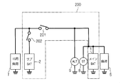
- FIG. 7 is a circuit diagram showing a configuration of a battery system in which the in-vehicle power supply device 200 supplies power not only to the general load 5 but also to the idling stop load 7.
- the in-vehicle power supply device 200 includes a main battery (indicated as “main BAT” in the drawing) 1, a sub battery (indicated as “sub BAT” in the drawing) 2, and relays 201 and 202.
- the load 5 is connected to the main battery 1 without passing through the relays 201 and 202.
- a failure for example, a ground fault, occurs on the main battery 1 side of the relay 201.
- the relays 201 and 202 are normally controlled so as to transition from the closed state to the open state in order to interrupt the overcurrent when it is detected. Therefore, when assumed as described above, an overcurrent starts to flow from the sub battery 2 via the relays 201 and 202, and the relay 202 is in an open state.
- the relay 202 is in the open state in this way, the power supply from the sub battery 2 to the idling stop load 7 is stopped. At this time, since a failure has occurred on the main battery 1 side, power is not substantially supplied to the idling stop load 7 regardless of whether the relay 201 is in a closed state or an open state.
- an object of the present invention is to provide a technology for supplying power to an external load while avoiding the occurrence of overcurrent even when either a failure on the main battery side or a failure on the sub battery side occurs. .
- Each of the in-vehicle power supply devices includes an in-vehicle main battery and an in-vehicle sub battery, a first switch and a second switch, and a main power supply path and a sub power supply path.
- the second switch is connected to the main battery via the first switch.
- the sub battery is connected to the main battery through the first switch and the second switch.
- the main power supply path bypasses the first switch and the second switch and connects the main battery to a load.
- the auxiliary power supply path connects the auxiliary battery to the load via the second switch.
- the first switch transitions from on to off when an overcurrent flows.
- the charging direction is a direction in which a current flows through the first switch when the main battery charges the sub battery.
- the in-vehicle power supply device supplies power to the outside while avoiding the occurrence of overcurrent even when either a failure on the main battery side or a failure on the sub battery side occurs.
- FIG. 10 is a circuit diagram showing an in-vehicle power supply device according to modification B. It is a circuit diagram which shows the prior art.
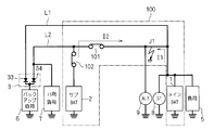
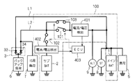
- FIG. 1 is a circuit diagram showing an in-vehicle power supply device 100 according to an embodiment and elements connected thereto.
- the in-vehicle power supply device 100 includes a main battery 1, a sub battery 2, relays 101 and 102, and circuits 401 and 402 (both expressed as “current / voltage detection” in the figure) for detecting current and voltage.
- the relays 101 and 102 are controlled by an in-vehicle ECU (electronic control unit) 403 in an open state / closed state.
- the vehicle-mounted ECU 403 causes the relays 101 and 102 to transition between the open state and the closed state when overvoltage or overcurrent is detected in the circuits 401 and 402.
- the main battery 1 and the sub battery 2 are both for vehicle use, and relays 101 and 102 are connected in series between them.
- Relay 101 is connected to main battery 1 via circuit 401
- relay 102 is connected to main battery 1 via relay 101 and circuit 401.
- the relays 101 and 102 can be grasped as switches whose closed / open states correspond to ON / OFF, respectively.
- the main battery 1 is charged from the outside of the in-vehicle power supply device 100. Specifically, the main battery 1 is connected to an on-vehicle alternator 9 and is charged by the power generation function of the alternator 9. The sub battery 2 is charged via the relays 101 and 102 by at least one of the alternator 9 and the main battery 1. For convenience of explanation to be described later, a direction in which a current flows through the relay 101 when the main battery 1 charges the sub battery 2 is referred to as a “charging direction”.
- the main battery 1 is, for example, a lead storage battery
- the secondary battery 2 is, for example, a lithium ion battery.
- Each of the main battery 1 and the sub battery 2 is a concept including a capacitor.
- an electric double layer capacitor may be employed for the sub battery 2.
- a starter 8 is connected to the main battery 1 together with a general load 5 from the outside of the in-vehicle power supply device 100.
- the load 5 is a load that is not subject to backup of the sub-battery 2, and is, for example, an in-vehicle air conditioner.
- the starter 8 is a motor that starts an engine (not shown). Since the load 5 and the starter 8 are known loads and do not have specific characteristics in the embodiment, detailed description thereof is omitted.
- the backup load 6 is a load for which power supply is desired to be maintained even when the power supply from the main battery 1 is lost, and examples include a shift-by-wire actuator and an electronically controlled braking force distribution system.
- the in-vehicle power supply device 100 further includes a main power supply path L1 and a sub power supply path L2, and supplies power to the backup load 6 through these.
- the main power supply path L1 connects the main battery 1, the load 5, and the backup load 6 in parallel with a fixed potential point (here, ground). That is, both the load 5 and the backup load 6 receive power via the main power supply path L1.
- the main power supply path L1 connects the main battery 1 and the backup load 6 without passing through the relays 101 and 102 (that is, bypassing them).
- the sub power feeding path L ⁇ b> 2 is connected to the sub battery 2 via the relay 102 and the circuit 402. Therefore, the backup load 6 can receive power not only from the main battery 1 but also from the sub battery 2.
- the diode group 3 is interposed between the backup load 6 and the main power supply path L1 and the sub power supply path L2.
- the diode group 3 prevents current from flowing between the main battery 1 and the sub battery 2 via the main power supply path L1 and the sub power supply path L2. This is because the wraparound causes deterioration of one or both of the main battery 1 and the sub battery 2.
- both the main battery 1 and the sub battery 2 supply power to the backup load 6 at a potential higher than ground.
- the cathodes of the pair of diodes 33 and 34 constituting the diode group 3 are connected in common and connected to the backup load 6.
- the anode of the diode 33 is connected to the main power supply path L1
- the anode of the diode 34 is connected to the sub power supply path L2.
- the charging direction described above is a direction from the main battery 1 toward the sub battery 2.
- the idling stop load 7 is connected to the auxiliary power supply path L2, and is connected to the auxiliary battery 2 via the relay 102 and the circuit 402. Further, it is connected to the main battery 1 via the relay 101 and the circuit 401.
- the connection relationship between the idling stop load 7 and the relays 101 and 102 and the main battery 1 and the sub battery 2 in the present embodiment is considered for the idling stop shown in FIG. 7 except for the circuits 401 and 402.
- the connection relationship between the load 7 and the relays 201 and 202 and the main battery 1 and the sub battery 2 is the same.
- the circuit 401 and the circuit 402 detect the voltage of the main battery 1 (hereinafter referred to as “main voltage”) and the voltage of the sub battery 2 (hereinafter referred to as “sub voltage”), respectively.
- main voltage the voltage of the main battery 1
- sub voltage the voltage of the sub battery 2
- the in-vehicle ECU 403 sets the open / closed state of the relays 101 and 102 as follows.
- the relays 101 and 102 are both closed and the sub-battery 2 is charged by the main battery 1 and / or the alternator 9. If the sub-voltage is high enough to determine that charging to the sub-battery 2 is excessive, the relay 101 is opened and charging to the sub-battery 2 is stopped. At this time, if the relay 102 is closed, power is supplied to the backup load 6 from the main power supply path L1 or the sub power supply path L2 depending on the magnitude relationship between the main voltage and the subvoltage.
- the closed state / open state of the relay 102 is selected according to the operation.
- such selection of the closed state / open state in the relay 102 when the secondary battery 2 is not charged in a normal state is not essential. Therefore, a detailed description of such selection is omitted.
- the circuit 401 detects the current flowing through the relay 101 (hereinafter referred to as “first current”) including the flowing direction. As will be described later, this is to know whether the direction in which the first current flows is the charging direction or the opposite direction.
- the charging direction is determined by positive / negative with respect to the ground potential of the power supplied by the main battery 1 and the sub battery 2. Therefore, if the configurations of the main battery and the sub battery 2 employed in the in-vehicle power supply device 100 are known, the charging direction is also known, and the direction in which the first current flows can be recognized from the sign of the first current.
- the charging direction is the direction from the main battery 1 to the sub battery 2 as described above.
- the first current is detected with the direction from the main battery 1 to the sub-battery 2 being positive, when the first current is positive, the direction in which the first current flows is the charging direction.
- the first current is negative, the direction in which the first current flows is opposite to the charging direction.
- the direction in which the first current flows is the charging direction when the first current is a negative value.
- the direction in which the first current flows is opposite to the charging direction.
- the charging direction is the direction from the sub battery 2 to the main battery 1.
- the direction in which the first current flows is the charging direction when the first current is a negative value.
- the direction in which the first current flows is opposite to the charging direction.
- the first current is detected with the direction from the sub battery 2 to the main battery 1 being positive, the direction in which the first current flows is the charging direction when the first current is a positive value.
- the first current is negative, the direction in which the first current flows is opposite to the charging direction.
- the anodes of the diodes 33 and 34 are commonly connected to the backup load 6 in the diode group 3, and the cathodes of the diodes 33 and 34 are connected to the main power supply path L1 and the sub power supply path L2, respectively.
- the in-vehicle ECU 403 determines that the first current (absolute value thereof) is an overcurrent, the in-vehicle ECU 403 opens the relay 101 even when the secondary battery 2 is being charged.
- the circuit 402 detects a current flowing through the relay 102 (hereinafter referred to as “second current”).
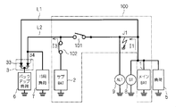
- FIG. 2 is a circuit diagram showing a situation in which the ground fault J1 occurs on the main battery 1 side than the relay 101 (more precisely, than the circuit 401) when the relays 101 and 102 are in the closed state. Due to the ground fault J1, not only the current I1 flows from the main battery 1 to the ground, but also the current I2 flows from the sub battery 2 to the ground via the relays 101 and 102. The same applies when a ground fault occurs in the main power supply path L1.
- the current I2 is a ground fault current and flows not only as the second current but also as the first current. Therefore, the circuits 401 and 402 detect both the first current and the second current as overcurrent.
- both the main battery 1 and the sub battery 2 are short-circuited by the ground fault J1, and power cannot be supplied from either the main power supply path L1 or the sub power supply path L2.
- the relays 101 and 102 are all opened, power supply from the auxiliary power supply path L2 is not continued.
- the current I2 flows as the first current in the direction opposite to the charging direction.
- the relay 102 when an overcurrent flowing in the direction opposite to the charging direction is detected as the first current, it is determined that no ground fault has occurred in the auxiliary power supply path L2, and the relay 102 is in the closed state.
- the relay 101 transitions from the closed state to the open state.
- the secondary battery 2 is disconnected from the ground fault J1, and the current I2, which is a ground fault current, does not flow.
- the sub battery 2 supplies the current I3 to the sub power feeding path L2. Since the current I3 is not a ground fault current, the circuit 402 does not determine that the second current is an overcurrent, and therefore the relay 102 remains closed.
- the secondary battery 2 functions as a backup power source for the backup load 6.
- FIG. 4 is a circuit showing a situation where a ground fault J2 occurs on the opposite side of the main battery 1 and the sub battery 2 from the relays 101 and 102, that is, in the sub power feeding path L2, when the relays 101 and 102 are in the closed state.
- a current I4 flows from the main battery 1 via the relay 101
- a current I5 flows from the sub battery 2 via the relay 102 to the ground.
- Currents I4 and I5 are ground fault currents, which respectively flow as a first current and a second current. Therefore, the circuits 401 and 402 detect both the first current and the second current as overcurrent.
- the current I4 flows in the charging direction as the first current.
- an overcurrent flowing in the charging direction is detected as the first current, it is determined that a ground fault has occurred in the sub-feeding path L2, and both of the relays 101 and 102 are closed. Transition to the open state.
- the main battery 1 and the sub battery 2 are isolated from the ground fault J2 as shown in FIG. Since the main power supply path L1 bypasses both of the relays 101 and 102 and is connected to the backup load 6, the current I6 flows from the main battery 1 through the main power supply path L1.
- the main battery 1 functions as a backup power source for the backup load 6.
- the main battery 1 functions as a backup power source for the backup load 6.
- the relay 101 is not transitioned to the closed state even if the overcurrent is not detected in the first current. This is to prevent the current I2 or the current I4 from flowing again as a ground fault current.
- the in-vehicle ECU 403 includes, for example, a microcomputer and a storage device.
- the microcomputer executes each processing step (in other words, a procedure) described in the program.
- the storage device can be composed of one or more of various storage devices such as ROM (Read Only Memory), RAM (Random Access Memory), and rewritable nonvolatile memory (EPROM (Erasable Programmable ROM), etc.).
- the storage device stores various information, data, and the like, stores a program executed by the microcomputer, and provides a work area for executing the program. It can be understood that the microcomputer functions as various means corresponding to each processing step described in the program, or can realize that various functions corresponding to each processing step are realized. Further, the in-vehicle ECU 403 is not limited to this, and various procedures executed by the in-vehicle ECU 403 or various means or various functions implemented may be realized by hardware.
- a circuit for controlling the relays 101 and 102 may be incorporated in either of the relays 101 and 102.
- the relay 102 when the overcurrent starts to flow through the relay 102, the relay 102 is maintained in the closed state for a predetermined period. When the overcurrent does not flow through the relay 101 within the predetermined period, the relay 102 changes from the closed state to the open state. Transition.
- the relay 103 should be in the open state with the transition from the closed state to the open state of the relay 101 so as not to hinder the effect of the relay 101 being in the open state in the operations (i) and (ii). Is desirable.
Landscapes
- Engineering & Computer Science (AREA)
- Power Engineering (AREA)
- Mechanical Engineering (AREA)
- Charge And Discharge Circuits For Batteries Or The Like (AREA)
Abstract
Provided is a feature in which power is supplied to an external load while generation of an overcurrent is circumvented even when a fault occurs on the main battery side or the sub-battery side. One relay is connected through the other relay to the main battery, and the sub-battery is connected through both of the relays to the main battery. A main power supply pathway circumvents both of the relays from the main battery to connect the main battery to a backup load. A sub-power supply pathway connects the sub-battery and the backup load to each other through the one relay. The other relay shifts from a closed state to an open state when an overcurrent flows, and the one relay shifts from a closed state to an open state when the overcurrent flows in the charging direction, which is the direction in which the current flows when the main battery charges the sub-battery. The one relay does not undergo the shift if the overcurrent flows in the direction opposite from the charging direction.
Description
この発明は、車載用電源装置に関する。
The present invention relates to an in-vehicle power supply device.
近年、車両負荷の電動化が進んでいる。そしてアイドリングストップを行うためにエンジンが停止した場合(以下「イグニッションオフ時」と仮称する)においても、給電されて駆動される負荷がある。かかる負荷を以下、アイドリングストップ用負荷(図面では「IS用負荷」と表示する)と称す。アイドリングストップ用負荷としては、例えばナビゲーション装置やオーディオ装置が挙げられる。
In recent years, motorization of vehicle loads has progressed. Even when the engine is stopped to perform idling stop (hereinafter, temporarily referred to as “ignition off”), there is a load that is powered and driven. Such a load is hereinafter referred to as an idling stop load (indicated as “IS load” in the drawing). Examples of the idling stop load include a navigation device and an audio device.
図7は、車載用電源装置200が一般の負荷5のみならずアイドリングストップ用負荷7にも給電するバッテリシステムの構成を示す回路図である。車載用電源装置200は主電池(図面において「メインBAT」と表記)1と副電池(図面において「サブBAT」と表記)2と、リレー201,202とを備える。負荷5はリレー201,202を介すること無く主電池1に接続される。
FIG. 7 is a circuit diagram showing a configuration of a battery system in which the in-vehicle power supply device 200 supplies power not only to the general load 5 but also to the idling stop load 7. The in-vehicle power supply device 200 includes a main battery (indicated as “main BAT” in the drawing) 1, a sub battery (indicated as “sub BAT” in the drawing) 2, and relays 201 and 202. The load 5 is connected to the main battery 1 without passing through the relays 201 and 202.
イグニッションがオンしてスターター8を駆動すると、オルタネータ9の発電機能によって主電池1が充電される。副電池2はリレー201,202を介して主電池1に接続される。アイドリングストップ用負荷7はリレー201を介して主電池1に、リレー202を介して副電池2に、それぞれ接続される。かかる技術は例えば下記の特許文献1に紹介されている。
When the ignition is turned on and the starter 8 is driven, the main battery 1 is charged by the power generation function of the alternator 9. The sub battery 2 is connected to the main battery 1 via relays 201 and 202. The idling stop load 7 is connected to the main battery 1 via the relay 201 and to the sub battery 2 via the relay 202. Such a technique is introduced in, for example, Patent Document 1 below.
リレー201よりも主電池1側において故障、例えば地絡が発生した場合を想定する。リレー201,202は通常、過電流を検出すると、これを遮断するためにクローズ状態からオープン状態へ遷移するように制御される。よって上述のように想定される場合には、副電池2からリレー201,202を介して過電流が流れ始め、リレー202はオープン状態となる。
Suppose a failure, for example, a ground fault, occurs on the main battery 1 side of the relay 201. The relays 201 and 202 are normally controlled so as to transition from the closed state to the open state in order to interrupt the overcurrent when it is detected. Therefore, when assumed as described above, an overcurrent starts to flow from the sub battery 2 via the relays 201 and 202, and the relay 202 is in an open state.
このようにリレー202がオープン状態となれば、副電池2からアイドリングストップ用負荷7への給電が停止してしまう。このとき主電池1側に故障が生じているので、リレー201がクローズ状態にあるかオープン状態にあるかによらず、アイドリングストップ用負荷7へは実質的に給電されない。
If the relay 202 is in the open state in this way, the power supply from the sub battery 2 to the idling stop load 7 is stopped. At this time, since a failure has occurred on the main battery 1 side, power is not substantially supplied to the idling stop load 7 regardless of whether the relay 201 is in a closed state or an open state.
さて、電動化される負荷には、走行、操舵、停止に関する機能を果たすものもある。よってバッテリ機能の消失(その機能不全を含む:以下同様)は回避されるべきである。この観点から、副電池をバックアップ用の電源として採用することも望ましい。
Now, some motorized loads perform functions related to running, steering, and stopping. Therefore, loss of battery function (including its malfunction: the same shall apply hereinafter) should be avoided. From this viewpoint, it is also desirable to employ a secondary battery as a backup power source.
そこで本発明は、主電池側の故障、副電池側の故障のいずれかが発生した場合においても、過電流の発生を回避しつつ、外部の負荷へ給電する技術を提供することを目的とする。
In view of the above, an object of the present invention is to provide a technology for supplying power to an external load while avoiding the occurrence of overcurrent even when either a failure on the main battery side or a failure on the sub battery side occurs. .
車載用電源装置は、いずれも車載用の主電池及び車載用の副電池と、第1スイッチ及び第2スイッチと、主給電経路及び副給電経路とを備える。前記第2スイッチは前記第1スイッチを介して前記主電池に接続される。前記副電池は前記第1スイッチ及び前記第2スイッチを介して前記主電池に接続される。前記主給電経路は前記第1スイッチ及び前記第2スイッチを迂回して前記主電池を負荷に接続する。前記副給電経路は前記第2スイッチを介して前記副電池を前記負荷に接続する。前記第1スイッチは過電流が流れるとオンからオフへ遷移する。前記第1スイッチに流れる過電流の向きが充電方向であれば前記第2スイッチがオンからオフへの遷移をし、前記第1スイッチに流れる過電流の向きが前記充電方向と逆向きであれば前記遷移をしない。前記充電方向は前記主電池が前記副電池を充電する際に前記第1スイッチを電流が流れる方向である。
Each of the in-vehicle power supply devices includes an in-vehicle main battery and an in-vehicle sub battery, a first switch and a second switch, and a main power supply path and a sub power supply path. The second switch is connected to the main battery via the first switch. The sub battery is connected to the main battery through the first switch and the second switch. The main power supply path bypasses the first switch and the second switch and connects the main battery to a load. The auxiliary power supply path connects the auxiliary battery to the load via the second switch. The first switch transitions from on to off when an overcurrent flows. If the direction of the overcurrent flowing through the first switch is the charging direction, the second switch transitions from on to off, and if the direction of the overcurrent flowing through the first switch is opposite to the charging direction The transition is not performed. The charging direction is a direction in which a current flows through the first switch when the main battery charges the sub battery.
車載用電源装置は、主電池側の故障、副電池側の故障のいずれかが発生した場合においても、過電流の発生を回避しつつ、外部に対して給電する。
The in-vehicle power supply device supplies power to the outside while avoiding the occurrence of overcurrent even when either a failure on the main battery side or a failure on the sub battery side occurs.
<構成>
図1は実施の形態に係る車載用電源装置100と、これに接続される要素とを示す回路図である。車載用電源装置100は主電池1、副電池2、リレー101,102、電流及び電圧の検出を行う回路401,402(いずれも図において「電流/電圧検出」と表記)を備える。リレー101,102は車載ECU(エレクトロニックコントロールユニット)403でそのオープン状態/クローズ状態が制御される。例えば車載ECU403は、回路401,402において過電圧又は過電流が検出された場合に、リレー101,102に、オープン状態とクローズ状態との間での遷移をさせる。 <Configuration>
FIG. 1 is a circuit diagram showing an in-vehiclepower supply device 100 according to an embodiment and elements connected thereto. The in-vehicle power supply device 100 includes a main battery 1, a sub battery 2, relays 101 and 102, and circuits 401 and 402 (both expressed as “current / voltage detection” in the figure) for detecting current and voltage. The relays 101 and 102 are controlled by an in-vehicle ECU (electronic control unit) 403 in an open state / closed state. For example, the vehicle-mounted ECU 403 causes the relays 101 and 102 to transition between the open state and the closed state when overvoltage or overcurrent is detected in the circuits 401 and 402.
図1は実施の形態に係る車載用電源装置100と、これに接続される要素とを示す回路図である。車載用電源装置100は主電池1、副電池2、リレー101,102、電流及び電圧の検出を行う回路401,402(いずれも図において「電流/電圧検出」と表記)を備える。リレー101,102は車載ECU(エレクトロニックコントロールユニット)403でそのオープン状態/クローズ状態が制御される。例えば車載ECU403は、回路401,402において過電圧又は過電流が検出された場合に、リレー101,102に、オープン状態とクローズ状態との間での遷移をさせる。 <Configuration>
FIG. 1 is a circuit diagram showing an in-vehicle
主電池1及び副電池2はいずれも車載用であって、両者の間にはリレー101,102が直列に接続される。リレー101は回路401を介して主電池1に接続され、リレー102はリレー101及び回路401を介して主電池1に接続される。リレー101,102は、クローズ状態/オープン状態がそれぞれオン/オフに対応するスイッチとして把握することができる。
The main battery 1 and the sub battery 2 are both for vehicle use, and relays 101 and 102 are connected in series between them. Relay 101 is connected to main battery 1 via circuit 401, and relay 102 is connected to main battery 1 via relay 101 and circuit 401. The relays 101 and 102 can be grasped as switches whose closed / open states correspond to ON / OFF, respectively.
主電池1は車載用電源装置100の外部から充電される。具体的には主電池1は車載されるオルタネータ9に接続され、オルタネータ9の発電機能によって充電される。副電池2はオルタネータ9及び主電池1の少なくとも何れか一方によってリレー101,102を介して充電される。後述する説明の便宜上、主電池1が副電池2を充電する際にリレー101に電流が流れる方向を「充電方向」と称する。
The main battery 1 is charged from the outside of the in-vehicle power supply device 100. Specifically, the main battery 1 is connected to an on-vehicle alternator 9 and is charged by the power generation function of the alternator 9. The sub battery 2 is charged via the relays 101 and 102 by at least one of the alternator 9 and the main battery 1. For convenience of explanation to be described later, a direction in which a current flows through the relay 101 when the main battery 1 charges the sub battery 2 is referred to as a “charging direction”.
主電池1には例えば鉛蓄電池が採用され、副電池2には例えばリチウムイオン電池が採用される。主電池1、副電池2はいずれもキャパシタを含む概念であり、例えば副電池2に電気二重層キャパシタを採用することもできる。
The main battery 1 is, for example, a lead storage battery, and the secondary battery 2 is, for example, a lithium ion battery. Each of the main battery 1 and the sub battery 2 is a concept including a capacitor. For example, an electric double layer capacitor may be employed for the sub battery 2.
主電池1には車載用電源装置100の外部から、一般の負荷5とともにスターター8が接続される。負荷5は副電池2のバックアップの対象とならない負荷であり、例えば車載エアコンディショナーである。スターター8は不図示のエンジンを始動させるモータである。負荷5およびスターター8は公知の負荷であり、実施の形態において特有の特徴を有する物ではないので、詳細な説明は省略する。
A starter 8 is connected to the main battery 1 together with a general load 5 from the outside of the in-vehicle power supply device 100. The load 5 is a load that is not subject to backup of the sub-battery 2, and is, for example, an in-vehicle air conditioner. The starter 8 is a motor that starts an engine (not shown). Since the load 5 and the starter 8 are known loads and do not have specific characteristics in the embodiment, detailed description thereof is omitted.
バックアップ負荷6は主電池1からの給電が消失しても電力供給が維持されることが望まれる負荷であり、シフトバイワイヤー用アクチュエータや、電子制御制動力配分システムを例として挙げることができる。
The backup load 6 is a load for which power supply is desired to be maintained even when the power supply from the main battery 1 is lost, and examples include a shift-by-wire actuator and an electronically controlled braking force distribution system.
車載用電源装置100は主給電経路L1と副給電経路L2とを更に備え、これらを介してバックアップ負荷6に給電する。主給電経路L1は固定電位点(ここでは接地)との間で、主電池1と、負荷5と、バックアップ負荷6を並列に接続する。つまり負荷5とバックアップ負荷6とは、いずれも主給電経路L1を介して受電する。
The in-vehicle power supply device 100 further includes a main power supply path L1 and a sub power supply path L2, and supplies power to the backup load 6 through these. The main power supply path L1 connects the main battery 1, the load 5, and the backup load 6 in parallel with a fixed potential point (here, ground). That is, both the load 5 and the backup load 6 receive power via the main power supply path L1.
主給電経路L1はリレー101,102を介すること無く(つまりこれらを迂回して)主電池1とバックアップ負荷6とを接続する。副給電経路L2は、リレー102及び回路402を介して副電池2と接続される。従って、バックアップ負荷6は主電池1からのみならず、副電池2からも受電可能である。
The main power supply path L1 connects the main battery 1 and the backup load 6 without passing through the relays 101 and 102 (that is, bypassing them). The sub power feeding path L <b> 2 is connected to the sub battery 2 via the relay 102 and the circuit 402. Therefore, the backup load 6 can receive power not only from the main battery 1 but also from the sub battery 2.
バックアップ負荷6と、主給電経路L1及び副給電経路L2との間にはダイオード群3が介在する。ダイオード群3は、主電池1と副電池2との間での、主給電経路L1及び副給電経路L2を経由した電流の回り込みを防止する。かかる回り込みは主電池1及び副電池2の一方もしくは双方の劣化を招くからである。
The diode group 3 is interposed between the backup load 6 and the main power supply path L1 and the sub power supply path L2. The diode group 3 prevents current from flowing between the main battery 1 and the sub battery 2 via the main power supply path L1 and the sub power supply path L2. This is because the wraparound causes deterioration of one or both of the main battery 1 and the sub battery 2.
ここでは主電池1及び副電池2のいずれもが接地よりも高い電位でバックアップ負荷6に給電する場合を想定する。ダイオード群3を構成する一対のダイオード33,34のカソードは共通に接続され、バックアップ負荷6に接続される。ダイオード33のアノードは主給電経路L1に、ダイオード34のアノードは副給電経路L2に、それぞれ接続される。この場合、上述した充電方向は主電池1から副電池2へ向かう方向である。
Here, it is assumed that both the main battery 1 and the sub battery 2 supply power to the backup load 6 at a potential higher than ground. The cathodes of the pair of diodes 33 and 34 constituting the diode group 3 are connected in common and connected to the backup load 6. The anode of the diode 33 is connected to the main power supply path L1, and the anode of the diode 34 is connected to the sub power supply path L2. In this case, the charging direction described above is a direction from the main battery 1 toward the sub battery 2.
このようにダイオード33,34の順方向が互いに逆向きに接続されているので、上述の電流の回り込みは防止される。しかもダイオード33を介して主給電経路L1から、あるいはダイオード34を介して副給電経路L2から、バックアップ負荷6への給電が可能である。
Thus, since the forward directions of the diodes 33 and 34 are connected in opposite directions, the above-described current wraparound is prevented. In addition, power can be supplied to the backup load 6 from the main power supply path L1 through the diode 33 or from the sub power supply path L2 through the diode 34.
アイドリングストップ用負荷7は副給電経路L2に接続され、リレー102及び回路402を介して副電池2に接続される。またリレー101及び回路401を介して主電池1に接続される。つまり、本実施の形態におけるアイドリングストップ用負荷7とリレー101,102並びに主電池1及び副電池2との接続関係は、回路401,402を除いて考えれば、図7で示されたアイドリングストップ用負荷7とリレー201,202並びに主電池1及び副電池2との接続関係と同様である。
The idling stop load 7 is connected to the auxiliary power supply path L2, and is connected to the auxiliary battery 2 via the relay 102 and the circuit 402. Further, it is connected to the main battery 1 via the relay 101 and the circuit 401. In other words, the connection relationship between the idling stop load 7 and the relays 101 and 102 and the main battery 1 and the sub battery 2 in the present embodiment is considered for the idling stop shown in FIG. 7 except for the circuits 401 and 402. The connection relationship between the load 7 and the relays 201 and 202 and the main battery 1 and the sub battery 2 is the same.
回路401及び回路402は、それぞれ主電池1の電圧(以下「主電圧」と称す)及び副電池2の電圧(以下「副電圧」と称す)を検出する。後述する過電流が発生していない場合、車載ECU403は以下のようにリレー101,102のオープン状態/クローズ状態を設定する。
The circuit 401 and the circuit 402 detect the voltage of the main battery 1 (hereinafter referred to as “main voltage”) and the voltage of the sub battery 2 (hereinafter referred to as “sub voltage”), respectively. When an overcurrent described later does not occur, the in-vehicle ECU 403 sets the open / closed state of the relays 101 and 102 as follows.
副電池2への充電が必要であると判断される程度に副電圧が低ければ、リレー101,102をいずれもクローズ状態とし、主電池1及び/又はオルタネータ9で副電池2を充電する。副電池2への充電が過剰であると判断される程度に副電圧が高ければリレー101をオープン状態とし、副電池2への充電を停止する。このとき、リレー102をクローズ状態とすればバックアップ負荷6には主電圧と副電圧との大小関係に依存して、主給電経路L1もしくは副給電経路L2から給電される。
If the sub-voltage is low enough to determine that the sub-battery 2 needs to be charged, the relays 101 and 102 are both closed and the sub-battery 2 is charged by the main battery 1 and / or the alternator 9. If the sub-voltage is high enough to determine that charging to the sub-battery 2 is excessive, the relay 101 is opened and charging to the sub-battery 2 is stopped. At this time, if the relay 102 is closed, power is supplied to the backup load 6 from the main power supply path L1 or the sub power supply path L2 depending on the magnitude relationship between the main voltage and the subvoltage.
副電池2を充電しない際には、動作に応じてリレー102のクローズ状態/オープン状態が選択される。本実施の形態では、正常時において副電池2を充電しないときのリレー102におけるこのようなクローズ状態/オープン状態の選択は本質的ではない。よってかかる選択についての詳細な説明は省略する。
When the secondary battery 2 is not charged, the closed state / open state of the relay 102 is selected according to the operation. In the present embodiment, such selection of the closed state / open state in the relay 102 when the secondary battery 2 is not charged in a normal state is not essential. Therefore, a detailed description of such selection is omitted.
回路401はリレー101に流れる電流(以下「第1電流」と称す)をその流れる方向も含めて検出する。後述するように第1電流の流れる向きが充電方向であるか、その逆方向であるかを了知するためである。充電方向は主電池1及び副電池2が給電する電位の接地電位に対する正負で決まる。よって車載用電源装置100において採用される主電池及び副電池2の構成が既知であれば、充電方向も既知であり、第1電流の流れる向きは第1電流の正負から了知できる。
The circuit 401 detects the current flowing through the relay 101 (hereinafter referred to as “first current”) including the flowing direction. As will be described later, this is to know whether the direction in which the first current flows is the charging direction or the opposite direction. The charging direction is determined by positive / negative with respect to the ground potential of the power supplied by the main battery 1 and the sub battery 2. Therefore, if the configurations of the main battery and the sub battery 2 employed in the in-vehicle power supply device 100 are known, the charging direction is also known, and the direction in which the first current flows can be recognized from the sign of the first current.
例えば主電池1及び副電池2が接地電位に対して正の電位で給電する場合、上述の様に充電方向は主電池1から副電池2へ向かう方向である。この場合に、主電池1から副電池2へ向かう方向を正にとって第1電流を検出すれば、第1電流が正値のときには第1電流の流れる方向は充電方向である。また第1電流が負値のときには第1電流の流れる方向は充電方向と逆方向である。
For example, when the main battery 1 and the sub battery 2 are fed with a positive potential with respect to the ground potential, the charging direction is the direction from the main battery 1 to the sub battery 2 as described above. In this case, if the first current is detected with the direction from the main battery 1 to the sub-battery 2 being positive, when the first current is positive, the direction in which the first current flows is the charging direction. When the first current is negative, the direction in which the first current flows is opposite to the charging direction.
また、この場合に、副電池2から主電池1へ向かう方向を正にとって第1電流を検出すれば、第1電流が負値のときには第1電流の流れる方向は充電方向である。また第1電流が正値のときには第1電流の流れる方向は充電方向と逆方向である。
In this case, if the first current is detected with the direction from the sub battery 2 to the main battery 1 being positive, the direction in which the first current flows is the charging direction when the first current is a negative value. When the first current is a positive value, the direction in which the first current flows is opposite to the charging direction.
あるいは、主電池1及び副電池2が接地電位に対して負の電位で給電する場合、充電方向は副電池2から主電池1へ向かう方向である。この場合に、主電池1から副電池2へ向かう方向を正にとって第1電流を検出すれば、第1電流が負値のときには第1電流の流れる方向は充電方向である。また第1電流が正値のときには第1電流の流れる方向は充電方向と逆方向である。副電池2から主電池1へ向かう方向を正にとって第1電流を検出すれば、第1電流が正値のときには第1電流の流れる方向は充電方向である。また第1電流が負値のときには第1電流の流れる方向は充電方向と逆方向である。
Alternatively, when the main battery 1 and the sub battery 2 are fed with a negative potential with respect to the ground potential, the charging direction is the direction from the sub battery 2 to the main battery 1. In this case, if the first current is detected assuming that the direction from the main battery 1 to the sub battery 2 is positive, the direction in which the first current flows is the charging direction when the first current is a negative value. When the first current is a positive value, the direction in which the first current flows is opposite to the charging direction. If the first current is detected with the direction from the sub battery 2 to the main battery 1 being positive, the direction in which the first current flows is the charging direction when the first current is a positive value. When the first current is negative, the direction in which the first current flows is opposite to the charging direction.
なおこの場合、ダイオード群3においてダイオード33,34のアノードが共通してバックアップ負荷6に接続され、ダイオード33,34のカソードが、それぞれ主給電経路L1及び副給電経路L2に接続される。
In this case, the anodes of the diodes 33 and 34 are commonly connected to the backup load 6 in the diode group 3, and the cathodes of the diodes 33 and 34 are connected to the main power supply path L1 and the sub power supply path L2, respectively.
車載ECU403は、第1電流(の絶対値)が過電流であると判断すれば、副電池2への充電時であっても、リレー101をオープン状態にする。回路402はリレー102に流れる電流(以下「第2電流」と称す)を検出する。
If the in-vehicle ECU 403 determines that the first current (absolute value thereof) is an overcurrent, the in-vehicle ECU 403 opens the relay 101 even when the secondary battery 2 is being charged. The circuit 402 detects a current flowing through the relay 102 (hereinafter referred to as “second current”).
<動作>
以下、本実施の形態の動作を説明するに当たり、図面の煩雑を回避するために、図2~図5では、図1から回路401,402、車載ECU403を省略した回路図を用いる。 <Operation>
Hereinafter, in describing the operation of the present embodiment, in order to avoid the complexity of the drawings, circuit diagrams in which the circuits 401 and 402 and the in-vehicle ECU 403 are omitted from FIGS.
以下、本実施の形態の動作を説明するに当たり、図面の煩雑を回避するために、図2~図5では、図1から回路401,402、車載ECU403を省略した回路図を用いる。 <Operation>
Hereinafter, in describing the operation of the present embodiment, in order to avoid the complexity of the drawings, circuit diagrams in which the
図2はリレー101,102がクローズ状態であるときに、リレー101よりも(より正確には回路401よりも)主電池1側で地絡J1が発生した状況を示す回路図である。地絡J1に起因して、主電池1から接地へ電流I1が流れるのみならず、副電池2からもリレー101,102を経由して電流I2が接地へ流れる。主給電経路L1において地絡が発生した場合も同様である。電流I2は地絡電流であり第2電流としてのみならず第1電流としても流れる。よって回路401,402は第1電流、第2電流のいずれについても過電流として検出する。
FIG. 2 is a circuit diagram showing a situation in which the ground fault J1 occurs on the main battery 1 side than the relay 101 (more precisely, than the circuit 401) when the relays 101 and 102 are in the closed state. Due to the ground fault J1, not only the current I1 flows from the main battery 1 to the ground, but also the current I2 flows from the sub battery 2 to the ground via the relays 101 and 102. The same applies when a ground fault occurs in the main power supply path L1. The current I2 is a ground fault current and flows not only as the second current but also as the first current. Therefore, the circuits 401 and 402 detect both the first current and the second current as overcurrent.
このような状態では地絡J1によって主電池1及び副電池2のいずれもが短絡することとなり、主給電経路L1、副給電経路L2のいずれからも給電を行うことはできない。しかしリレー101,102を全てオープン状態にすれば、副給電経路L2からの給電は引き続き行われなくなる。
In such a state, both the main battery 1 and the sub battery 2 are short-circuited by the ground fault J1, and power cannot be supplied from either the main power supply path L1 or the sub power supply path L2. However, if the relays 101 and 102 are all opened, power supply from the auxiliary power supply path L2 is not continued.
電流I2は第1電流として、充電方向とは逆方向に流れる。本実施の形態では、第1電流として充電方向とは逆方向に流れる過電流が検出された場合には、副給電経路L2には地絡が発生していないと判断し、リレー102がクローズ状態のままでリレー101がクローズ状態からオープン状態へ遷移する。これにより、またダイオード群3の機能により、図3に示されるように副電池2は地絡J1から遮断され、地絡電流たる電流I2は流れない。その代わり副電池2は副給電経路L2に電流I3を流す。電流I3は地絡電流ではないので、回路402は第2電流が過電流であるとの判断をせず、従ってリレー102はクローズ状態を維持する。
The current I2 flows as the first current in the direction opposite to the charging direction. In the present embodiment, when an overcurrent flowing in the direction opposite to the charging direction is detected as the first current, it is determined that no ground fault has occurred in the auxiliary power supply path L2, and the relay 102 is in the closed state. The relay 101 transitions from the closed state to the open state. Thereby, due to the function of the diode group 3, as shown in FIG. 3, the secondary battery 2 is disconnected from the ground fault J1, and the current I2, which is a ground fault current, does not flow. Instead, the sub battery 2 supplies the current I3 to the sub power feeding path L2. Since the current I3 is not a ground fault current, the circuit 402 does not determine that the second current is an overcurrent, and therefore the relay 102 remains closed.
よって電流I3によって、副給電経路L2からバックアップ負荷6及びアイドリングストップ用負荷7への給電が行われる。つまり副電池2はバックアップ負荷6に対するバックアップ用電源として機能する。このようにして主電池1側に故障が発生した場合であっても、過電流の発生を回避しつつ、外部への給電が確保される。
Therefore, power is supplied from the auxiliary power supply path L2 to the backup load 6 and the idling stop load 7 by the current I3. That is, the secondary battery 2 functions as a backup power source for the backup load 6. Thus, even when a failure occurs on the main battery 1 side, power supply to the outside is ensured while avoiding the occurrence of overcurrent.
図4はリレー101,102がクローズ状態であるときに、リレー101,102に対して主電池1及び副電池2とは反対側、つまり副給電経路L2において地絡J2が発生した状況を示す回路図である。地絡J2に起因して、主電池1からはリレー101を経由して電流I4が、副電池2からはリレー102を経由して電流I5が、それぞれ接地へ流れる。電流I4,I5は地絡電流であり、それぞれ第1電流及び第2電流として流れる。よって回路401,402は第1電流、第2電流のいずれについても過電流として検出する。
FIG. 4 is a circuit showing a situation where a ground fault J2 occurs on the opposite side of the main battery 1 and the sub battery 2 from the relays 101 and 102, that is, in the sub power feeding path L2, when the relays 101 and 102 are in the closed state. FIG. Due to the ground fault J2, a current I4 flows from the main battery 1 via the relay 101, and a current I5 flows from the sub battery 2 via the relay 102 to the ground. Currents I4 and I5 are ground fault currents, which respectively flow as a first current and a second current. Therefore, the circuits 401 and 402 detect both the first current and the second current as overcurrent.
電流I4は第1電流として、充電方向に流れる。本実施の形態では、第1電流として充電方向に流れる過電流が検出された場合には、副給電経路L2に地絡が発生していると判断し、リレー101,102の両方をクローズ状態からオープン状態へ遷移する。これにより、またダイオード群3の機能により、図5に示されるように主電池1及び副電池2は地絡J2から遮断される。主給電経路L1はリレー101,102の両方を迂回してバックアップ負荷6に接続されているので、主給電経路L1には主電池1から電流I6が流れる。
The current I4 flows in the charging direction as the first current. In the present embodiment, when an overcurrent flowing in the charging direction is detected as the first current, it is determined that a ground fault has occurred in the sub-feeding path L2, and both of the relays 101 and 102 are closed. Transition to the open state. As a result, the main battery 1 and the sub battery 2 are isolated from the ground fault J2 as shown in FIG. Since the main power supply path L1 bypasses both of the relays 101 and 102 and is connected to the backup load 6, the current I6 flows from the main battery 1 through the main power supply path L1.
よって電流I6によって、主給電経路L1からバックアップ負荷6への給電が行われる。つまり主電池1はバックアップ負荷6に対するバックアップ用電源として機能する。このようにして副電池2側に故障が発生した場合においても、過電流の発生を回避しつつ、外部への給電が確保される。
Therefore, power is supplied from the main power supply path L1 to the backup load 6 by the current I6. That is, the main battery 1 functions as a backup power source for the backup load 6. Thus, even when a failure occurs on the side of the secondary battery 2, power supply to the outside is ensured while avoiding the occurrence of overcurrent.
なお、第1電流として過電流が検出されてリレー101を一旦オープン状態にした後は、第1電流に過電流が検出されなくてもリレー101をクローズ状態に遷移させない。再び電流I2、あるいは電流I4が地絡電流として流れないようにするためである。
Note that after the overcurrent is detected as the first current and the relay 101 is once opened, the relay 101 is not transitioned to the closed state even if the overcurrent is not detected in the first current. This is to prevent the current I2 or the current I4 from flowing again as a ground fault current.
以上のことから、主電池1側の故障(典型的には上述の地絡J1)及び副電池2側の故障(典型的には上述の地絡J2)のいずれか一方のみが発生している場合には、下記処理によって奏功することが分かる。これは車載用電源装置100を制御する方法であると把握することができる。
From the above, only one of the failure on the main battery 1 side (typically the above-mentioned ground fault J1) and the fault on the sub battery 2 side (typically the above-mentioned ground fault J2) has occurred. In some cases, it can be seen that the following processing is successful. This can be understood as a method of controlling the in-vehicle power supply device 100.
リレー101,102のいずれもクローズ状態である状況において:
(i)第1電流が充電方向に流れる過電流であることを検出した場合、リレー101,102がクローズ状態からオープン状態へ遷移する;
(ii)第1電流が充電方向と逆方向に流れる過電流であることを検出した場合、リレー101はクローズ状態からオープン状態へ遷移するが、リレー102はクローズ状態を維持する。 In the situation where both relays 101 and 102 are closed:
(i) When it is detected that the first current is an overcurrent flowing in the charging direction, the relays 101 and 102 transition from the closed state to the open state;
(ii) When it is detected that the first current is an overcurrent flowing in the direction opposite to the charging direction, therelay 101 transitions from the closed state to the open state, but the relay 102 maintains the closed state.
(i)第1電流が充電方向に流れる過電流であることを検出した場合、リレー101,102がクローズ状態からオープン状態へ遷移する;
(ii)第1電流が充電方向と逆方向に流れる過電流であることを検出した場合、リレー101はクローズ状態からオープン状態へ遷移するが、リレー102はクローズ状態を維持する。 In the situation where both
(i) When it is detected that the first current is an overcurrent flowing in the charging direction, the
(ii) When it is detected that the first current is an overcurrent flowing in the direction opposite to the charging direction, the
地絡J2のみが発生している場合には上記(i)の動作は実行されるが、上記(ii)の動作は実行されない。地絡J1のみが発生している場合には上記(i)の動作は実行されないが、上記(ii)の動作が実行される。
When only the ground fault J2 occurs, the operation (i) is executed, but the operation (ii) is not executed. When only the ground fault J1 occurs, the operation (i) is not executed, but the operation (ii) is executed.
車載ECU403は例えばマイクロコンピュータと記憶装置を含んで構成される。マイクロコンピュータは、プログラムに記述された各処理ステップ(換言すれば手順)を実行する。上記記憶装置は、例えばROM(Read Only Memory)、RAM(Random Access Memory)、書き換え可能な不揮発性メモリ(EPROM(Erasable Programmable ROM)等)などの各種記憶装置の1つ又は複数で構成可能である。当該記憶装置は、各種の情報やデータ等を格納し、またマイクロコンピュータが実行するプログラムを格納し、また、プログラムを実行するための作業領域を提供する。なお、マイクロコンピュータは、プログラムに記述された各処理ステップに対応する各種手段として機能するとも把握でき、あるいは、各処理ステップに対応する各種機能を実現するとも把握できる。また、車載ECU403はこれに限らず、車載ECU403によって実行される各種手順、あるいは実現される各種手段又は各種機能の一部又は全部をハードウェアで実現しても構わない。
The in-vehicle ECU 403 includes, for example, a microcomputer and a storage device. The microcomputer executes each processing step (in other words, a procedure) described in the program. The storage device can be composed of one or more of various storage devices such as ROM (Read Only Memory), RAM (Random Access Memory), and rewritable nonvolatile memory (EPROM (Erasable Programmable ROM), etc.). . The storage device stores various information, data, and the like, stores a program executed by the microcomputer, and provides a work area for executing the program. It can be understood that the microcomputer functions as various means corresponding to each processing step described in the program, or can realize that various functions corresponding to each processing step are realized. Further, the in-vehicle ECU 403 is not limited to this, and various procedures executed by the in-vehicle ECU 403 or various means or various functions implemented may be realized by hardware.
また、上記リレー101,102の制御を行う回路を、リレー101,102のいずれかに内蔵させてもよい。
Also, a circuit for controlling the relays 101 and 102 may be incorporated in either of the relays 101 and 102.
<変形A>
地絡J1,J2のいずれが発生した場合でも、第1電流のみならず第2電流も過電流となる。よってリレー101がクローズ状態からオープン状態へ遷移するよりも前に、リレー102がクローズ状態からオープン状態へ遷移する(以下「逆行動作」と称す)可能性がある。 <Deformation A>
When any of the ground faults J1 and J2 occurs, not only the first current but also the second current becomes an overcurrent. Therefore, before therelay 101 transits from the closed state to the open state, the relay 102 may transit from the closed state to the open state (hereinafter referred to as “reverse operation”).
地絡J1,J2のいずれが発生した場合でも、第1電流のみならず第2電流も過電流となる。よってリレー101がクローズ状態からオープン状態へ遷移するよりも前に、リレー102がクローズ状態からオープン状態へ遷移する(以下「逆行動作」と称す)可能性がある。 <Deformation A>
When any of the ground faults J1 and J2 occurs, not only the first current but also the second current becomes an overcurrent. Therefore, before the
地絡J1が発生した場合に逆行動作が生じると、第1電流が流れず、従ってリレー101はクローズ状態を維持する。しかしながら、「発明が解決しようとする課題」で述べた理由により、リレー101がクローズ状態を維持しても主電池1から副給電経路L2を介した給電は行われない。
If the reverse operation occurs when the ground fault J1 occurs, the first current does not flow, and therefore the relay 101 maintains the closed state. However, for the reason described in “Problems to be Solved by the Invention”, power is not supplied from the main battery 1 via the auxiliary power supply path L2 even if the relay 101 is kept closed.
そこで、リレー102に過電流が流れ始めた後(換言すれば第2電流が過電流であると検出された後)の所定期間内にリレー101に過電流が流れたか否か(換言すれば第1電流が過電流であると検出されたか否か)の判断を、リレー102がクローズ状態からオープン状態へ遷移するよりも前に行うことが望ましい。
Therefore, whether or not an overcurrent has flown through the relay 101 within a predetermined period after the overcurrent starts flowing through the relay 102 (in other words, after the second current is detected to be overcurrent) (in other words, the first It is desirable to determine whether or not one current is detected as an overcurrent before the relay 102 transitions from the closed state to the open state.
より具体的にはリレー102に過電流が流れ始めてから所定期間内はリレー102のクローズ状態を維持し、所定期間内にリレー101に過電流が流れない場合、リレー102がクローズ状態からオープン状態へ遷移する。
More specifically, when the overcurrent starts to flow through the relay 102, the relay 102 is maintained in the closed state for a predetermined period. When the overcurrent does not flow through the relay 101 within the predetermined period, the relay 102 changes from the closed state to the open state. Transition.
これにより逆行動作が避けられるのみならず、地絡J1,J2以外の原因で発生する故障から副電池2を保護できる。
This not only prevents reverse operation, but also protects the sub-battery 2 from failures that occur due to causes other than the ground faults J1 and J2.
<変形B>
イグニッションオフ時にはオルタネータ9による発電機能は期待できず、主電池1への充電も期待できない。よって主電池1から副電池2への充電経路を遮断する観点で、主電池1と副電池2との分離が望ましい。よってリレー101,102にノーマリーオープン型を採用することが望ましい。リレー101,102をスイッチとして把握する場合、ノーマリーオープン型をノーマリーオフ型と把握することができる。 <Deformation B>
When the ignition is off, the power generation function by thealternator 9 cannot be expected, and the main battery 1 cannot be charged. Therefore, it is desirable to separate the main battery 1 and the sub battery 2 from the viewpoint of blocking the charging path from the main battery 1 to the sub battery 2. Therefore, it is desirable to adopt a normally open type for the relays 101 and 102. When the relays 101 and 102 are grasped as switches, the normally open type can be grasped as a normally off type.
イグニッションオフ時にはオルタネータ9による発電機能は期待できず、主電池1への充電も期待できない。よって主電池1から副電池2への充電経路を遮断する観点で、主電池1と副電池2との分離が望ましい。よってリレー101,102にノーマリーオープン型を採用することが望ましい。リレー101,102をスイッチとして把握する場合、ノーマリーオープン型をノーマリーオフ型と把握することができる。 <Deformation B>
When the ignition is off, the power generation function by the
他方、アイドリングストップ用負荷7にはイグニッションオフ時においても給電することが望ましい。よって図6に示すように、リレー101とは並列にノーマリークローズ型のリレー103を接続することが望ましい。イグニッションオフ時においても主電池1から副給電経路L2を介してのアイドリングストップ用負荷7への給電を確保するためである。リレー103をスイッチとして把握する場合、ノーマリークローズ型をノーマリーオン型と把握することができる。
On the other hand, it is desirable to supply power to the idling stop load 7 even when the ignition is off. Therefore, as shown in FIG. 6, it is desirable to connect a normally closed relay 103 in parallel with the relay 101. This is because power supply from the main battery 1 to the idling stop load 7 via the sub power supply path L2 is ensured even when the ignition is off. When grasping the relay 103 as a switch, a normally closed type can be grasped as a normally on type.
この場合、車載ECU403の機能不全あるいは失陥によってノーマリーオープン型のリレー101,102がオープン状態になったとしても、ノーマリークローズ型のリレー103がクローズ状態にあることによって、主電池1から副給電経路L2を介してのアイドリングストップ用負荷7への給電も確保される。
In this case, even if the normally open relays 101 and 102 are in an open state due to malfunction or failure of the in-vehicle ECU 403, the normally closed relay 103 is in a closed state. Power supply to the idling stop load 7 through the power supply path L2 is also ensured.
但し、上記(i),(ii)の動作においてリレー101がオープン状態となることの効果を妨げないよう、リレー103はリレー101のクローズ状態からオープン状態への遷移に伴ってオープン状態にすることが望ましい。
However, the relay 103 should be in the open state with the transition from the closed state to the open state of the relay 101 so as not to hinder the effect of the relay 101 being in the open state in the operations (i) and (ii). Is desirable.
上記の実施の形態並びに変形A及び変形Bで説明された構成は、互いに矛盾しない限り適宜に組み合わせることができる。
The configurations described in the above embodiment and the modifications A and B can be appropriately combined as long as they do not contradict each other.
以上のようにこの発明は詳細に説明されたが、上記した説明は、すべての局面において、例示であって、この発明がそれに限定されるものではない。例示されていない無数の変形例が、この発明の範囲から外れることなく想定され得るものと解される。
Although the present invention has been described in detail as described above, the above description is illustrative in all aspects, and the present invention is not limited thereto. It is understood that countless variations that are not illustrated can be envisaged without departing from the scope of the present invention.
1 主電池
2 副電池
6 バックアップ負荷
7 アイドリングストップ用負荷
101,102,103 リレー
L1 主給電経路
L2 副給電経路 DESCRIPTION OFSYMBOLS 1 Main battery 2 Sub battery 6 Backup load 7 Idling stop load 101,102,103 Relay L1 Main power supply path L2 Sub power supply path
2 副電池
6 バックアップ負荷
7 アイドリングストップ用負荷
101,102,103 リレー
L1 主給電経路
L2 副給電経路 DESCRIPTION OF
Claims (6)
- 車載用の主電池と、
過電流が流れるとオンからオフへ遷移する第1スイッチ、
前記第1スイッチを介して前記主電池に接続され、前記第1スイッチに流れる過電流の向きが充電方向であればオンからオフへの遷移をし、前記第1スイッチに流れる過電流の向きが前記充電方向と逆向きであれば前記遷移をしない第2スイッチと、
前記第1スイッチ及び前記第2スイッチを介して前記主電池に接続される車載用の副電池と、
前記第1スイッチ及び前記第2スイッチを迂回して前記主電池を負荷に接続する主給電経路と、
前記第2スイッチを介して前記副電池を前記負荷に接続する副給電経路と
を備え、
前記充電方向は前記主電池が前記副電池を充電する際に前記第1スイッチを電流が流れる方向である、車載用電源装置。 A main battery for in-vehicle use,
A first switch that transitions from on to off when an overcurrent flows;
If the direction of the overcurrent that is connected to the main battery via the first switch and flows through the first switch is in the charging direction, the transition is made from on to off, and the direction of the overcurrent that flows through the first switch is A second switch that does not make the transition if the charging direction is opposite;
A vehicle-mounted sub battery connected to the main battery via the first switch and the second switch;
A main power supply path that bypasses the first switch and the second switch and connects the main battery to a load;
A secondary power supply path for connecting the secondary battery to the load via the second switch,
The in-vehicle power supply device, wherein the charging direction is a direction in which a current flows through the first switch when the main battery charges the sub battery. - 請求項1記載の車載用電源装置であって、
前記第2スイッチは自身に過電流が流れ始めた後の所定期間はオンを維持し、前記所定期間内に前記第1スイッチに過電流が流れない場合に前記第2スイッチはオンからオフへ遷移する、車載用電源装置。 The in-vehicle power supply device according to claim 1,
The second switch remains on for a predetermined period after the overcurrent starts flowing in itself, and the second switch transitions from on to off when no overcurrent flows to the first switch within the predetermined period. An in-vehicle power supply. - 請求項1又は請求項2に記載の車載用電源装置であって、
前記第1スイッチと並列に接続されたノーマリーオン型の第3スイッチ
を更に備え、
前記第1スイッチ及び前記第2スイッチはノーマリーオフ型であり、
前記第3スイッチは前記第1スイッチのオンからオフへの遷移に伴ってオフする、車載用電源装置。 The in-vehicle power supply device according to claim 1 or 2,
A normally-on type third switch connected in parallel with the first switch;
The first switch and the second switch are normally off type,
The on-vehicle power supply device, wherein the third switch is turned off with the transition of the first switch from on to off. - 車載用の主電池と、
第1スイッチと、
前記第1スイッチを介して前記主電池に接続される第2スイッチと、
前記第1スイッチ及び前記第2スイッチを介して前記主電池に接続される車載用の副電池と、
前記第1スイッチ及び前記第2スイッチを迂回して前記主電池を負荷に接続する主給電経路と、
前記第2スイッチを介して前記副電池を前記負荷に接続する副給電経路と
を備える車載用電源装置を制御する方法であって、
前記第1スイッチに過電流が流れた場合に前記第1スイッチをオンからオフに遷移させ、
前記第1スイッチに流れる過電流の向きが充電方向であれば前記第2スイッチにオンからオフへの遷移をさせ、前記第1スイッチに流れる過電流の向きが前記充電方向と逆向きであれば前記遷移をさせず、
前記充電方向は前記主電池が前記副電池を充電する際に前記第1スイッチを電流が流れる方向である、車載用電源装置の制御方法。 A main battery for in-vehicle use,
A first switch;
A second switch connected to the main battery via the first switch;
A vehicle-mounted sub battery connected to the main battery via the first switch and the second switch;
A main power supply path that bypasses the first switch and the second switch and connects the main battery to a load;
A method for controlling an in-vehicle power supply device comprising a sub-feeding path for connecting the sub-battery to the load via the second switch,
When an overcurrent flows through the first switch, the first switch is transitioned from on to off,
If the direction of the overcurrent flowing through the first switch is the charging direction, the second switch is caused to transition from on to off, and if the direction of the overcurrent flowing through the first switch is opposite to the charging direction Without making the transition,
The on-vehicle power supply control method, wherein the charging direction is a direction in which a current flows through the first switch when the main battery charges the sub battery. - 請求項4記載の車載用電源装置の制御方法であって、
前記第2スイッチに過電流が流れ始めた後の所定期間はオンを維持し、前記所定期間内に前記第1スイッチに過電流が流れない場合に前記第2スイッチをオンからオフへ遷移させる、車載用電源装置の制御方法。 It is a control method of the vehicle-mounted power supply device of Claim 4, Comprising:
The on-state is maintained on for a predetermined period after the overcurrent starts to flow through the second switch, and the second switch is transitioned from on to off when no overcurrent flows through the first switch within the predetermined period. Control method for in-vehicle power supply device. - 請求項4又は請求項5に記載の車載用電源装置の制御方法であって、
前記車載用電源装置は前記第1スイッチと並列に接続されたノーマリーオン型の第3スイッチ
を更に備え、
前記第1スイッチ及び前記第2スイッチはノーマリーオフ型であり、
前記第3スイッチを前記第1スイッチのオンからオフへの遷移に伴ってオフさせる、車載用電源装置の制御方法。 A control method for an in-vehicle power supply device according to claim 4 or 5,
The in-vehicle power supply device further includes a normally-on type third switch connected in parallel with the first switch,
The first switch and the second switch are normally off type,
A control method for an in-vehicle power supply device, wherein the third switch is turned off with a transition from on to off of the first switch.
Priority Applications (2)
| Application Number | Priority Date | Filing Date | Title |
|---|---|---|---|
| US15/762,779 US20190071039A1 (en) | 2015-09-25 | 2016-09-21 | In-vehicle power supply device and control method for the same |
| CN201680054346.7A CN108028545A (en) | 2015-09-25 | 2016-09-21 | Vehicle-mounted supply unit and its control method |
Applications Claiming Priority (2)
| Application Number | Priority Date | Filing Date | Title |
|---|---|---|---|
| JP2015187699A JP2017061240A (en) | 2015-09-25 | 2015-09-25 | On-vehicle power supply device and method for control thereof |
| JP2015-187699 | 2015-09-25 |
Publications (1)
| Publication Number | Publication Date |
|---|---|
| WO2017051812A1 true WO2017051812A1 (en) | 2017-03-30 |
Family
ID=58386842
Family Applications (1)
| Application Number | Title | Priority Date | Filing Date |
|---|---|---|---|
| PCT/JP2016/077762 WO2017051812A1 (en) | 2015-09-25 | 2016-09-21 | In-car power supply device and method for controlling same |
Country Status (4)
| Country | Link |
|---|---|
| US (1) | US20190071039A1 (en) |
| JP (1) | JP2017061240A (en) |
| CN (1) | CN108028545A (en) |
| WO (1) | WO2017051812A1 (en) |
Cited By (1)
| Publication number | Priority date | Publication date | Assignee | Title |
|---|---|---|---|---|
| WO2022085673A1 (en) * | 2020-10-23 | 2022-04-28 | 株式会社アイシン | Shift device and electronic control unit for vehicle |
Families Citing this family (7)
| Publication number | Priority date | Publication date | Assignee | Title |
|---|---|---|---|---|
| JP6540565B2 (en) * | 2016-03-16 | 2019-07-10 | 株式会社オートネットワーク技術研究所 | Power supply system for vehicle, drive system for vehicle |
| JP6651941B2 (en) * | 2016-03-30 | 2020-02-19 | 株式会社オートネットワーク技術研究所 | Switch device and control device for vehicle power supply |
| KR101932279B1 (en) | 2018-03-19 | 2019-01-02 | 주식회사 경신 | Apparatus and method for controlling power of a vehicle |
| JP7108962B2 (en) * | 2018-12-03 | 2022-07-29 | 株式会社オートネットワーク技術研究所 | In-vehicle backup power supply control device and in-vehicle backup power supply device |
| JP7017139B2 (en) * | 2018-12-26 | 2022-02-08 | 株式会社デンソー | Energization control device and power supply system |
| DE102019125067A1 (en) | 2019-09-18 | 2021-03-18 | Ford Global Technologies, Llc | Method for operating an on-board network of a motor vehicle |
| US20220263323A1 (en) * | 2021-02-16 | 2022-08-18 | Denso Ten Limited | Power supply device and control method |
Citations (4)
| Publication number | Priority date | Publication date | Assignee | Title |
|---|---|---|---|---|
| JP2010088180A (en) * | 2008-09-30 | 2010-04-15 | Panasonic Corp | Energy storage device |
| JP2012130108A (en) * | 2010-12-13 | 2012-07-05 | Denso Corp | Power supply |
| JP2015076959A (en) * | 2013-10-08 | 2015-04-20 | 株式会社オートネットワーク技術研究所 | Power system |
| JP2015154618A (en) * | 2014-02-14 | 2015-08-24 | 株式会社デンソー | battery unit |
Family Cites Families (4)
| Publication number | Priority date | Publication date | Assignee | Title |
|---|---|---|---|---|
| WO2010026715A1 (en) * | 2008-09-08 | 2010-03-11 | 株式会社オートネットワーク技術研究所 | Power supply device for vehicle |
| CN102811887B (en) * | 2010-03-29 | 2015-12-02 | 松下知识产权经营株式会社 | Vehicle power source device |
| JP5396446B2 (en) * | 2011-08-30 | 2014-01-22 | 日立オートモティブシステムズ株式会社 | In-vehicle power supply |
| CN104057901B (en) * | 2014-06-27 | 2016-04-27 | 深圳市金能弘盛能源科技有限公司 | A kind of automobile super capacitor module power-supply management system |
-
2015
- 2015-09-25 JP JP2015187699A patent/JP2017061240A/en active Pending
-
2016
- 2016-09-21 WO PCT/JP2016/077762 patent/WO2017051812A1/en active Application Filing
- 2016-09-21 US US15/762,779 patent/US20190071039A1/en not_active Abandoned
- 2016-09-21 CN CN201680054346.7A patent/CN108028545A/en active Pending
Patent Citations (4)
| Publication number | Priority date | Publication date | Assignee | Title |
|---|---|---|---|---|
| JP2010088180A (en) * | 2008-09-30 | 2010-04-15 | Panasonic Corp | Energy storage device |
| JP2012130108A (en) * | 2010-12-13 | 2012-07-05 | Denso Corp | Power supply |
| JP2015076959A (en) * | 2013-10-08 | 2015-04-20 | 株式会社オートネットワーク技術研究所 | Power system |
| JP2015154618A (en) * | 2014-02-14 | 2015-08-24 | 株式会社デンソー | battery unit |
Cited By (2)
| Publication number | Priority date | Publication date | Assignee | Title |
|---|---|---|---|---|
| WO2022085673A1 (en) * | 2020-10-23 | 2022-04-28 | 株式会社アイシン | Shift device and electronic control unit for vehicle |
| JP7380909B2 (en) | 2020-10-23 | 2023-11-15 | 株式会社アイシン | Shift devices and vehicle electronic control units |
Also Published As
| Publication number | Publication date |
|---|---|
| US20190071039A1 (en) | 2019-03-07 |
| JP2017061240A (en) | 2017-03-30 |
| CN108028545A (en) | 2018-05-11 |
Similar Documents
| Publication | Publication Date | Title |
|---|---|---|
| WO2017051812A1 (en) | In-car power supply device and method for controlling same | |
| JP6398931B2 (en) | In-vehicle power supply device and control method thereof | |
| CN108602478B (en) | Switching device for vehicle-mounted power supply and vehicle-mounted power supply device | |
| US10279761B2 (en) | Vehicle power-supply device | |
| US10549705B2 (en) | Switch device for on-board power supply and on-board power supply device | |
| US10992165B2 (en) | Redundant power supply system | |
| US10399518B2 (en) | Relay device and power supply device | |
| WO2018088111A1 (en) | Power supply control apparatus and battery unit | |
| JP2018196252A (en) | Power Distribution System | |
| WO2017159485A1 (en) | Vehicular power supply system, vehicular driving system | |
| WO2017169817A1 (en) | On-vehicle power source switch apparatus and control apparatus | |
| WO2018047636A1 (en) | On-vehicle backup device | |
| JP2014030281A (en) | Power-supply system | |
| JP6915430B2 (en) | Power system | |
| JP6627732B2 (en) | Power supply circuit device | |
| JP6690396B2 (en) | Relay device | |
| JP2019195249A (en) | Vehicle power supply system | |
| JP6903951B2 (en) | Power system | |
| JP2016187236A (en) | Battery system control device | |
| JP6750558B2 (en) | Power box | |
| WO2017183512A1 (en) | Switch device for in-vehicle power supply, and in-vehicle power supply system | |
| JP6176186B2 (en) | Automotive power supply | |
| JP2017052473A (en) | On-vehicle power supply device | |
| JP2019135819A (en) | Power semiconductor device, and vehicle power supplying system comprising the same | |
| JP2015221594A (en) | Power source device of automobile |
Legal Events
| Date | Code | Title | Description |
|---|---|---|---|
| 121 | Ep: the epo has been informed by wipo that ep was designated in this application |
Ref document number: 16848600 Country of ref document: EP Kind code of ref document: A1 |
|
| NENP | Non-entry into the national phase |
Ref country code: DE |
|
| 122 | Ep: pct application non-entry in european phase |
Ref document number: 16848600 Country of ref document: EP Kind code of ref document: A1 |