WO2017026261A1 - Motor control device, electric power steering device, and vehicle - Google Patents
Motor control device, electric power steering device, and vehicle Download PDFInfo
- Publication number
- WO2017026261A1 WO2017026261A1 PCT/JP2016/071747 JP2016071747W WO2017026261A1 WO 2017026261 A1 WO2017026261 A1 WO 2017026261A1 JP 2016071747 W JP2016071747 W JP 2016071747W WO 2017026261 A1 WO2017026261 A1 WO 2017026261A1
- Authority
- WO
- WIPO (PCT)
- Prior art keywords
- motor
- electrical angle
- motor electrical
- angle
- unit
- Prior art date
Links
Images


Classifications
-
- B—PERFORMING OPERATIONS; TRANSPORTING
- B62—LAND VEHICLES FOR TRAVELLING OTHERWISE THAN ON RAILS
- B62D—MOTOR VEHICLES; TRAILERS
- B62D5/00—Power-assisted or power-driven steering
- B62D5/04—Power-assisted or power-driven steering electrical, e.g. using an electric servo-motor connected to, or forming part of, the steering gear
- B62D5/0457—Power-assisted or power-driven steering electrical, e.g. using an electric servo-motor connected to, or forming part of, the steering gear characterised by control features of the drive means as such
- B62D5/0481—Power-assisted or power-driven steering electrical, e.g. using an electric servo-motor connected to, or forming part of, the steering gear characterised by control features of the drive means as such monitoring the steering system, e.g. failures
- B62D5/0484—Power-assisted or power-driven steering electrical, e.g. using an electric servo-motor connected to, or forming part of, the steering gear characterised by control features of the drive means as such monitoring the steering system, e.g. failures for reaction to failures, e.g. limp home
-
- B—PERFORMING OPERATIONS; TRANSPORTING
- B62—LAND VEHICLES FOR TRAVELLING OTHERWISE THAN ON RAILS
- B62D—MOTOR VEHICLES; TRAILERS
- B62D5/00—Power-assisted or power-driven steering
- B62D5/04—Power-assisted or power-driven steering electrical, e.g. using an electric servo-motor connected to, or forming part of, the steering gear
- B62D5/0409—Electric motor acting on the steering column
-
- B—PERFORMING OPERATIONS; TRANSPORTING
- B62—LAND VEHICLES FOR TRAVELLING OTHERWISE THAN ON RAILS
- B62D—MOTOR VEHICLES; TRAILERS
- B62D5/00—Power-assisted or power-driven steering
- B62D5/04—Power-assisted or power-driven steering electrical, e.g. using an electric servo-motor connected to, or forming part of, the steering gear
- B62D5/0457—Power-assisted or power-driven steering electrical, e.g. using an electric servo-motor connected to, or forming part of, the steering gear characterised by control features of the drive means as such
- B62D5/046—Controlling the motor
- B62D5/0463—Controlling the motor calculating assisting torque from the motor based on driver input
-
- B—PERFORMING OPERATIONS; TRANSPORTING
- B62—LAND VEHICLES FOR TRAVELLING OTHERWISE THAN ON RAILS
- B62D—MOTOR VEHICLES; TRAILERS
- B62D5/00—Power-assisted or power-driven steering
- B62D5/04—Power-assisted or power-driven steering electrical, e.g. using an electric servo-motor connected to, or forming part of, the steering gear
- B62D5/0457—Power-assisted or power-driven steering electrical, e.g. using an electric servo-motor connected to, or forming part of, the steering gear characterised by control features of the drive means as such
- B62D5/0481—Power-assisted or power-driven steering electrical, e.g. using an electric servo-motor connected to, or forming part of, the steering gear characterised by control features of the drive means as such monitoring the steering system, e.g. failures
- B62D5/0487—Power-assisted or power-driven steering electrical, e.g. using an electric servo-motor connected to, or forming part of, the steering gear characterised by control features of the drive means as such monitoring the steering system, e.g. failures detecting motor faults
-
- B—PERFORMING OPERATIONS; TRANSPORTING
- B62—LAND VEHICLES FOR TRAVELLING OTHERWISE THAN ON RAILS
- B62D—MOTOR VEHICLES; TRAILERS
- B62D5/00—Power-assisted or power-driven steering
- B62D5/04—Power-assisted or power-driven steering electrical, e.g. using an electric servo-motor connected to, or forming part of, the steering gear
- B62D5/0457—Power-assisted or power-driven steering electrical, e.g. using an electric servo-motor connected to, or forming part of, the steering gear characterised by control features of the drive means as such
- B62D5/0481—Power-assisted or power-driven steering electrical, e.g. using an electric servo-motor connected to, or forming part of, the steering gear characterised by control features of the drive means as such monitoring the steering system, e.g. failures
- B62D5/049—Power-assisted or power-driven steering electrical, e.g. using an electric servo-motor connected to, or forming part of, the steering gear characterised by control features of the drive means as such monitoring the steering system, e.g. failures detecting sensor failures
-
- H—ELECTRICITY
- H02—GENERATION; CONVERSION OR DISTRIBUTION OF ELECTRIC POWER
- H02P—CONTROL OR REGULATION OF ELECTRIC MOTORS, ELECTRIC GENERATORS OR DYNAMO-ELECTRIC CONVERTERS; CONTROLLING TRANSFORMERS, REACTORS OR CHOKE COILS
- H02P29/00—Arrangements for regulating or controlling electric motors, appropriate for both AC and DC motors
- H02P29/02—Providing protection against overload without automatic interruption of supply
- H02P29/024—Detecting a fault condition, e.g. short circuit, locked rotor, open circuit or loss of load
- H02P29/028—Detecting a fault condition, e.g. short circuit, locked rotor, open circuit or loss of load the motor continuing operation despite the fault condition, e.g. eliminating, compensating for or remedying the fault
-
- H—ELECTRICITY
- H02—GENERATION; CONVERSION OR DISTRIBUTION OF ELECTRIC POWER
- H02P—CONTROL OR REGULATION OF ELECTRIC MOTORS, ELECTRIC GENERATORS OR DYNAMO-ELECTRIC CONVERTERS; CONTROLLING TRANSFORMERS, REACTORS OR CHOKE COILS
- H02P29/00—Arrangements for regulating or controlling electric motors, appropriate for both AC and DC motors
- H02P29/02—Providing protection against overload without automatic interruption of supply
- H02P29/032—Preventing damage to the motor, e.g. setting individual current limits for different drive conditions
-
- H—ELECTRICITY
- H02—GENERATION; CONVERSION OR DISTRIBUTION OF ELECTRIC POWER
- H02P—CONTROL OR REGULATION OF ELECTRIC MOTORS, ELECTRIC GENERATORS OR DYNAMO-ELECTRIC CONVERTERS; CONTROLLING TRANSFORMERS, REACTORS OR CHOKE COILS
- H02P6/00—Arrangements for controlling synchronous motors or other dynamo-electric motors using electronic commutation dependent on the rotor position; Electronic commutators therefor
- H02P6/14—Electronic commutators
- H02P6/16—Circuit arrangements for detecting position
-
- H—ELECTRICITY
- H02—GENERATION; CONVERSION OR DISTRIBUTION OF ELECTRIC POWER
- H02P—CONTROL OR REGULATION OF ELECTRIC MOTORS, ELECTRIC GENERATORS OR DYNAMO-ELECTRIC CONVERTERS; CONTROLLING TRANSFORMERS, REACTORS OR CHOKE COILS
- H02P2203/00—Indexing scheme relating to controlling arrangements characterised by the means for detecting the position of the rotor
- H02P2203/05—Determination of the rotor position by using two different methods and/or motor models
Definitions
- the present invention relates to a motor control device that drives and controls a multiphase electric motor mounted on an electric power steering device.
- a control device for a multiphase rotating machine described in Patent Document 1 As a motor control device for controlling an electric motor of an electric power steering device mounted on a vehicle, for example, a control device for a multiphase rotating machine described in Patent Document 1 is disclosed.
- the rotor rotational position ⁇ is detected by a position sensor such as a resolver, and the U-phase which is a three-phase voltage command value based on the command voltages Vd1, Vq1 and the rotor rotational position ⁇ .
- the command voltage Vuu * 1, the V-phase command voltage Vvu * 1, and the W-phase command voltage Vwu * 1 are calculated.
- An object of the present invention is to provide a motor control device, an electric power steering device, and a vehicle capable of driving control.
- the motor control device generates the steering angle reference value and the steering assist force detected by the steering angle detector that detects the steering angle of the steering.
- An offset amount estimation unit that estimates a relative offset amount with respect to the origin of the motor electrical angle of the multiphase electric motor
- a motor electrical angle estimation unit that estimates the motor electrical angle based on the steering angle and the relative offset amount
- the motor control device generates a steering assist force based on the steering angle detected by the steering angle detection unit that detects the steering angle of the steering.
- the motor electrical angle estimation unit for estimating the motor electrical angle of the multiphase electric motor and the motor electrical angle detection unit for detecting the motor electrical angle are normal, based on the motor electrical angle detected by the motor electrical angle detection unit
- a motor drive control unit that drives and controls the multiphase electric motor, and when the motor electrical angle detection unit is abnormal, drives and controls the multiphase electric motor based on a motor electrical angle estimation value estimated by the motor electrical angle estimation unit; Is provided.
- An electric power steering apparatus includes the motor control apparatus according to the first or second aspect.
- a vehicle according to a fourth aspect of the present invention includes the electric power steering device according to the third aspect.
- the relative offset amount between the steering angle reference value detected by the steering angle detector and the origin of the motor electrical angle of the multiphase electric motor is estimated, and the steering angle and the relative offset amount are estimated.
- the motor electrical angle is estimated.
- the motor electrical angle of the multiphase electric motor is estimated based on the steering angle detected by the steering angle detection unit.
- the motor electrical angle detector that detects the motor electrical angle is abnormal, the multiphase electric motor can be driven and controlled based on the estimated motor electrical angle estimated by the motor electrical angle estimator. As a result, even when the motor electrical angle detection unit is abnormal, it is possible to continuously drive the multiphase electric motor.
- the electric power steering apparatus is configured to include the motor control apparatus having the above-described effects, the multiphase electric motor can be driven and controlled by the estimated motor electric angle even when an abnormality occurs in the motor electric angle detection unit.
- the steering assist function of the electric power steering device can be continued.
- the vehicle is configured to include the electric power steering device having the above-described effects, the steering assist function of the electric power steering device can be continued even when an abnormality occurs in the motor electrical angle detection unit. It becomes possible to improve.
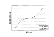
- 1 is a schematic configuration diagram illustrating a torque sensor according to a first embodiment of the present invention. It is sectional drawing which shows the structure of the three-phase electric motor which concerns on 1st Embodiment of this invention. It is a schematic diagram which shows the winding structure of the three-phase electric motor of FIG. It is a circuit diagram which shows the specific structure of the motor control apparatus which concerns on 1st Embodiment of this invention. It is a characteristic diagram which shows the relationship between the steering torque at the time of normal, and a steering auxiliary current command value. It is a characteristic diagram which shows the relationship between the steering torque at the time of abnormality, and a steering auxiliary current command value.
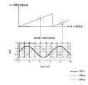
- (A) is a wave form diagram which shows an example of the torque command value for estimating a motor electrical angle origin
- (b) and (c) are the time of inputting the drive current by a step-wave-like command value to an electric motor. It is a wave form diagram which shows an example of the response waveform of an output torque.
- FIGS. 16 (a) and 16 (c) are diagrams showing interphase counter electromotive voltage waveforms during motor positive / negative rotation
- FIGS. 16 (b) and (d) are amplitudes of interphase counter electromotive voltage waveforms during motor positive / negative rotation. It is a figure which shows the relationship of a relationship and a code
- first to fifth embodiments of the present invention will be described with reference to the drawings.
- the same or similar parts are denoted by the same or similar reference numerals.
- the drawings are schematic, and dimensional relationships and ratios may differ from actual ones.
- the following first to fifth embodiments exemplify apparatuses and methods for embodying the technical idea of the present invention, and the technical idea of the present invention is the material of components, The shape, structure, arrangement, etc. are not specified below.
- the technical idea of the present invention can be variously modified within the technical scope defined by the claims described in the claims.
- the vehicle 1 includes front wheels 2FR and 2FL and rear wheels 2RR and 2RL which are left and right steered wheels.
- the front wheels 2FR and 2FL are steered by the electric power steering device 3.
- the electric power steering device 3 has a steering wheel 11, and a steering force applied to the steering wheel 11 from a driver is transmitted to the steering shaft 12.
- the steering shaft 12 has an input shaft 12a and an output shaft 12b. One end of the input shaft 12a is connected to the steering wheel 11, and the other end is connected to one end of the output shaft 12b via the torque sensor 13.
- the steering force transmitted to the output shaft 12b is transmitted to the lower shaft 15 via the universal joint 14, and further transmitted to the pinion shaft 17 via the universal joint 16.
- the steering force transmitted to the pinion shaft 17 is transmitted to the tie rod 19 via the steering gear 18 to steer the front wheels 2FR and 2FL as steered wheels.
- the steering gear 18 is configured in a rack and pinion type having a pinion 18a coupled to the pinion shaft 17 and a rack 18b meshing with the pinion 18a. Therefore, the steering gear 18 converts the rotational motion transmitted to the pinion 18a into the straight motion in the vehicle width direction by the rack 18b.
- a steering assist mechanism 20 that transmits a steering assist force to the output shaft 12b is connected to the output shaft 12b of the steering shaft 12.
- the steering assist mechanism 20 is a multiphase composed of, for example, a three-phase brushless motor that generates a steering assist force that is connected to the reduction gear 21 and a reduction gear 21 that is connected to the output shaft 12b.
- a three-phase electric motor 22 as an electric motor.
- the torque sensor 13 detects the steering torque applied to the steering wheel 11 and transmitted to the input shaft 12a. As shown in FIG.
- the torque sensor 13 converts the steering torque into a torsional angular displacement of a torsion bar 13a (not shown) interposed between the input shaft 12a and the output shaft 12b, and converts the torsional angular displacement into the input shaft 12a.
- the input side rotation angle sensor 13b arranged on the output side and the output side rotation angle sensor 13c arranged on the output shaft 12b side are converted into an angle difference and detected.
- the input side rotation angle sensor 13b and the output side rotation angle sensor 13c are sensors that detect relative rotation angles.
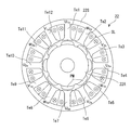
- the three-phase electric motor 22 includes a stator 22S having teeth Te that are formed inwardly on the inner peripheral surface to form a slot SL, and an inner peripheral side of the stator 22S. And an 8-pole surface magnet type rotor 22R having a permanent magnet PM disposed on the surface thereof so as to be rotatably opposed to the teeth Te.
- the first three-phase motor winding L1 and the second three-phase motor winding L1 which are the same phase with respect to the rotor magnet in the two systems shown in FIG. Two three-phase motor windings L2 are wound.
- the first three-phase motor winding L1 is star-connected by connecting one end of each of U-phase coils U1a and U1b, V-phase coils V1a and V1b, and W-phase coils W1a and W1b.
- U-phase coils U1a and U1b, the V-phase coils V1a and V1b, and the W-phase coils W1a and W1b are connected to the motor control device 25, and motor drive currents I1u, I1v, and I1w are individually supplied. .
- the second three-phase motor winding L2 is star-connected by connecting one end of each of U-phase coils U2a and U2b, V-phase coils V2a and V2b, and W-phase coils W2a and W2b. Furthermore, the other ends of the U-phase coils U2a and U2b, the V-phase coils V2a and V2b, and the W-phase coils W2a and W2b are connected to the motor control device 25, and motor drive currents I2u, I2v, and I2w are individually supplied.
- phase coil portions U1a, U1b, V1a, V1b and W1a, W1b of the first three-phase motor winding L1 and the phase coil portions U2a, U2b, V2a, V2b of the second three-phase motor winding L2 and W2a and W2b are wound around slots SL sandwiching the teeth Te so that the directions of the energization currents are the same.
- phase coil portions U1a, U1b, V1a, V1b and W1a, W1b of the first three-phase motor winding L1 and the phase coil portions U2a, U2b, V2a, of the second three-phase motor winding L2, V2b and W2a and W2b are wound around 12 different teeth Te1 to Te12.
- phase coils U1a, U1b, V1a, V1b and W1a, W1b, which are the first system are sequentially wound around the 12 teeth Te1 to Te12 in the same winding direction in the clockwise direction, and then the second system
- the phase coils U2a, U2b, V2a, V2b and W2a, W2b are wound in the same winding direction in the clockwise direction.
- the phase coils U1a, U1b, V1a, V1b and W1a, W1b which are the first system are wound in the same winding direction in the clockwise direction, and finally, the phase coils U2a, U2b, V2a which are the second system.
- each coil part of the first three-phase motor winding L1 and each coil part of the second three-phase motor winding L2 constitute a magnetic circuit that minimizes mutual magnetic interference. .
- the three-phase electric motor 22 includes a rotational position sensor 23a configured from a resolver that detects the rotational position of the rotor.
- the detection value from the rotational position sensor 23a is supplied to the motor electrical angle detection circuit 23, and the motor electrical angle detection circuit 23 detects the motor electrical angle ⁇ m.
- the rotational position sensor 23a is not limited to the resolver, and may be composed of other sensors such as a rotary encoder. Further, the rotational position sensor 23a may be hereinafter referred to as “resolver 23a”.
- the motor control device 25 receives the steering torque T detected by the torque sensor 13 and the vehicle speed Vs detected by the vehicle speed sensor 26 and the motor electrical angle ⁇ m output from the motor electrical angle detection circuit 23.
- a direct current is input to the motor control device 25 from a battery 27 as a direct current source.
- the negative electrode of the battery 27 is grounded, and the positive electrode thereof is connected to the motor control device 25 via an ignition switch 28 (hereinafter sometimes referred to as “IGN switch 28”) for starting the engine, and IGN. It is directly connected to the motor control device 25 without going through the switch 28.
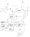
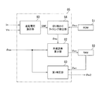
- the specific configuration of the motor control device 25 is configured as shown in FIG. That is, the motor control device 25 includes a control calculation device 31 for calculating a motor current command value, and first and second motor drive circuits 32A to which motor current command values output from the control calculation device 31 are individually input. And 32B, and the first and second three-phase motor windings L1 and L2 of the three-phase electric motor 22 and the first and second motor drive circuits 32A and 32B. 1 and second motor current cut-off circuits 33A and 33B.
- the control arithmetic unit 31 receives the steering torque T detected by the torque sensor 13 and the vehicle speed Vs detected by the vehicle speed sensor 26 shown in FIG. As shown, the motor electrical angle ⁇ m output from the motor electrical angle detection circuit 23 is input. Further, the motor current I1m (output from the coils of the respective phases of the first three-phase motor winding L1 and the second three-phase motor winding L2 of the three-phase electric motor 22 output from the current detection circuits 34A and 34B ( I1mu, I1mv, I1mw) and I2m (I2mu, I2mv, I2mw) are input.
- the detected value may be described as “motor current detected value Im (Imu, Imv, Imw)”.
- the control arithmetic unit 31 includes a voltage provided between the first and second motor drive circuits 32A and 32B and the first and second motor current cutoff circuits 33A and 33B.
- Motor phase voltages V1m (V1mu, V1mv, V1mw) and V2m (V2mu, V2mv, V2mw) detected by the detection circuits 40A and 40B are input.
- the detected value may be described as “motor voltage detected value Vm (Vmu, Vmv, Vmw)”.
- the control arithmetic unit 31 when the first and second motor drive circuits 32A and 32B are normal, refer to the normal-time steering auxiliary current command value calculation map shown in FIG. 6 set in advance based on the steering torque T and the vehicle speed Vs. Then, steering assist current command values I1 * and I2 * are calculated. Further, in the control arithmetic unit 31, when the first and second motor drive circuits 32A or 32B are abnormal, the abnormal-time steering auxiliary current command value calculation map shown in FIG. 7 preset based on the steering torque T and the vehicle speed Vs is shown. , Steering assist current command values I1 * and I2 * are calculated.
- the target d-axis current command value Id * and the target q-axis current command value in the dq coordinate system based on the calculated steering assist current command values I1 * and I2 * and the motor electrical angle ⁇ m. Iq * is calculated.
- the control arithmetic unit 31 converts the calculated d-axis current command value Id * and q-axis current command value Iq * into dq-phase to three-phase to convert the U-phase current command value Iu * , the V-phase current command value Iv *, and W-phase current command value Iw * is calculated.
- the control arithmetic unit 31 then calculates the U-phase current command value Iu * , the V-phase current command value Iv *, the W-phase current command value Iw *, and the current detection values detected by the current detection circuits 34A and 34B for each phase. Current deviations ⁇ Iu, ⁇ Iv, and ⁇ Iw from the added value are calculated. Still further, the control arithmetic unit 31 performs, for example, a PI control calculation or a PID control calculation on the calculated current deviations ⁇ Iu, ⁇ Ib, and ⁇ Iw, and performs a three-phase voltage command value V1 for the first and second motor drive circuits 32A and 32B. * And V2 * are calculated. Then, the calculated three-phase voltage command values V1 * and V2 * are output to the first and second motor drive circuits 32A and 32B.
- control arithmetic device 31 is provided between the first and second motor current cutoff circuits 33A and 33B and the first and second three-phase motor windings L1 and L2 of the three-phase electric motor 22.
- Motor current detection values I1mu, I1mv, I1mw and I2mu, I2mv, I2mw detected by the first and second abnormality detection circuits 35A and 35B are input.
- the control arithmetic unit 31 compares the input motor current detection values I1mu to I1mw and I2mu to I2mw with the respective phase current command values Iu * , Iv * and Iw * calculated by itself.
- an abnormality detection unit 31a for detecting open failures and short-circuit failures of field effect transistors (FETs) Q1 to Q6 as switching elements constituting first and second inverter circuits 42A and 42B described later is provided. I have.
- the first and second motors that have detected an abnormality when detecting an open failure or a short failure of the field effect transistors (FETs) constituting the first and second inverter circuits 42A and 42B.
- An abnormality detection signal SAa or SAb having a logical value “1” is output to the gate drive circuit 41A or 41B of the drive circuit 32A or 32B.
- Each of the first and second motor drive circuits 32A and 32B includes a gate drive circuit 41A and 41B having an abnormal current control unit 41a, and first and second inverter circuits 42A and 42B.
- the gate drive circuits 41A and 41B receive the three-phase voltage command values V1 * and V2 * output from the control arithmetic unit 31.
- a gate signal is formed based on the input three-phase voltage command values V1 * and V2 * .
- the first and second inverter circuits 42A and 42B receive the gate signals output from the gate drive circuits 41A and 41B. Then, a drive current is supplied to the three-phase electric motor 22 based on the input gate signal.
- each of the gate drive circuits 41A and 41B performs a pulse based on the voltage command values V1 * and V2 * and the triangular carrier signal Sc.
- Six gate signals that are width-modulated (PWM) are formed. These gate signals are output to the first and second inverter circuits 42A and 42B.
- the gate drive circuit 41A has three gates with a high level relative to the first motor current cutoff circuit 33A. Output a signal.
- two high-level gate signals are output to the first power cutoff circuit 44A.
- the gate drive circuit 41A is configured to provide three low-level gates with respect to the first motor current cutoff circuit 33A by the abnormal current control unit 41a. Simultaneously outputs signals and cuts off motor current. In addition, two low-level gate signals are simultaneously output to the first power cut-off circuit 44A to cut off battery power.
- the gate drive circuit 41B has three high levels with respect to the second motor current cutoff circuit 33B. Outputs a gate signal. In addition, two high-level gate signals are output to the second power cutoff circuit 44B. Further, when the abnormality detection signal SAb is a logical value “1” (abnormal), the gate drive circuit 41B has three low-level gates with respect to the second motor current cutoff circuit 33B in the abnormal current control unit 41a. Simultaneously outputs signals and cuts off motor current. In addition, two low-level gate signals are simultaneously output to the second power cutoff circuit 44B to cut off the battery power.
- first and second inverter circuits 42A and 42B the battery current of the battery 27 is input via the noise filter 43 and the first and second power shut-off circuits 44A and 44B, and smoothing electrolysis is performed on the input side.
- Capacitors CA and CB are connected.
- These first and second inverter circuits 42A and 42B have field effect transistors (FETs) Q1 to Q6 as six switching elements, and three switching arms SAu in which two field effect transistors are connected in series. It has a configuration in which SAv and SAw are connected in parallel.
- the gate signals output from the gate drive circuits 41A and 41B are input to the gates of the field effect transistors Q1 to Q6.
- the U-phase current Iu, the V-phase current Iv, and the W-phase current Iw pass through the first and second motor current cutoff circuits 33A and 33B from between the field effect transistors of the switching arms SAu, SAv, and SAw. It is output to the first and second three-phase motor windings L1 and L2 of the electric motor 22.
- the voltage across the shunt resistor inserted between the switching arms SAu, SAv and SAw of the first and second inverter circuits 42A and 42B and the ground is input to the current detection circuits 34A and 34B.
- the These current detection circuits 34A and 34B detect motor currents I1m (I1mu to I1mw) and I2m (I2mu to I2mw).
- the first motor current cut-off circuit 33A has three current cut-off field effect transistors QA1, QA2, and QA3.
- the source of the field effect transistor QA1 is connected to the connection point between the field effect transistors Q1 and Q2 of the switching arm SAu of the first inverter circuit 42A, and the drain is connected to the first three-phase motor winding via the first abnormality detection circuit 35A. It is connected to U-phase coils U1a and U1b of line L1.
- the source of the field effect transistor QA2 is connected to the connection point of the field effect transistors Q3 and Q4 of the switching arm SAv of the first inverter circuit 42A, and the drain is connected to the first three-phase via the first abnormality detection circuit 35A.
- the motor winding L1 is connected to the V-phase coils V1a and V1b.
- the source of the field effect transistor QA3 is connected to the connection point of the field effect transistors Q5 and Q6 of the switching arm SAw of the first inverter circuit 42A, and the drain is connected to the first three-phase via the first abnormality detection circuit 35A.
- the motor winding L1 is connected to the W-phase coils W1a and W1b.
- the second motor current cut-off circuit 33B has three current cut-off field effect transistors QB1, QB2, and QB3.
- the source of the field effect transistor QB1 is connected to the connection point between the field effect transistors Q1 and Q2 of the switching arm SBu of the second inverter circuit 42B, and the drain is connected to the second three-phase motor winding via the second abnormality detection circuit 35B. It is connected to U-phase coils U2a and U2b of line L2.
- the source of the field effect transistor QB2 is connected to the connection point of the field effect transistors Q3 and Q4 of the switching arm SBv of the second inverter circuit 42B, and the drain is connected to the second three-phase via the first abnormality detection circuit 35A.
- the motor winding L2 is connected to the V phase coils V2a and V2b. Further, the source of the field effect transistor QB3 is connected to the connection point of the field effect transistors Q5 and Q6 of the switching arm SBw of the second inverter circuit 42B, and the drain is connected to the second three-phase via the first abnormality detection circuit 35A. The motor winding L2 is connected to the W-phase coils W2a and W2b.
- the field effect transistors QA1 to QA3 and QB1 to QB3 of the first and second motor current cut-off circuits 33A and 33B have the cathodes of the respective parasitic diodes D as the first and second inverter circuits 42A and 42B, respectively. Connected in the same direction.
- Each of the first and second power cutoff circuits 44A and 44B has a series circuit configuration in which two field effect transistors (FETs) QC1, QC2 and QD1, QD2 connect the drains and the parasitic diodes are reversed.
- FETs field effect transistors
- the sources of the field effect transistors QC1 and QD1 are connected to each other and connected to the output side of the noise filter 43. Further, the sources of the field effect transistors QC2 and QD2 are connected to the sources of the field effect transistors Q1, Q2 and Q3 of the first and second inverter circuits 42B and 42B.
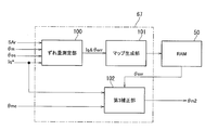
- the motor electrical angle detection circuit 23 of the first embodiment includes a main motor electrical angle detection circuit 23b, a sub motor electrical angle detection circuit 23c, an electrical angle selection unit 23d, a RAM 50, and a ROM 51.
- the main motor electrical angle detection circuit 23 b includes an angle calculation unit 60 and a resolver abnormality diagnosis unit 61.
- the angle calculation unit 60 calculates the first motor electrical angle ⁇ m1 based on the sin signal and the cos signal corresponding to the rotation angle of the three-phase electric motor 22 output from the resolver 23a. Then, the calculated first motor electrical angle ⁇ m1 is output to the electrical angle selector 23d.
- the resolver abnormality diagnosis unit 61 detects an abnormality of the resolver 23a and outputs an abnormality detection signal SAr.
- the sub-motor electrical angle detection circuit 23c outputs the output shaft rotation angle ⁇ os output from the output side rotation angle sensor 13c, the steering torque T, and the IGN switch 28.
- An ignition signal IGN indicating ON / OFF of the ignition is input.
- the first motor electrical angle ⁇ m1 from the angle calculation unit 60 and the abnormality detection signal SAr from the resolver abnormality diagnosis unit 61 are input.
- the sub motor electrical angle detection circuit 23 c includes a relative offset amount estimation unit 62 and a motor electrical angle estimation unit 63.
- the relative offset amount estimation unit 62 estimates the relative offset amount ⁇ off between the origin ⁇ md of the motor electrical angle ⁇ m (hereinafter sometimes referred to as “motor electrical angle origin ⁇ md”) and the reference value ⁇ osr of the output shaft rotation angle ⁇ os. To do. Then, the estimated relative offset amount ⁇ off is output to the motor electrical angle estimation unit 63.
- the motor electrical angle estimator 63 reads from the ROM 51 the previously stored reduction ratio RGr of the reduction gear 21 and the pole pair number P of the rotor 22R of the three-phase electric motor 22.
- the motor electrical angle The estimated value ⁇ me is calculated. Further, the calculated motor electrical angle estimated value ⁇ me is output as the second motor electrical angle ⁇ m2 to the electrical angle selector 23d.
- the motor electrical angle estimation unit 63 calculates the motor electrical angle estimated value ⁇ me according to the following equation (1).
- ⁇ me ⁇ os ⁇ RGr ⁇ P + ⁇ off (1) That is, the motor electrical angle estimated value ⁇ me is calculated by multiplying the output shaft rotation angle detection value ⁇ os by the reduction ratio RGr and the pole pair number P, and adding the relative offset amount ⁇ off to the multiplication result.
- the electrical angle selection unit 23d is configured to detect the main motor electrical angle detection circuit 23b. The first motor electrical angle ⁇ m1 output from is selected.
- the selected first motor electrical angle ⁇ m1 is output as the motor electrical angle ⁇ m to the control arithmetic unit 31 described above.
- the abnormality detection signal SAr is a logical value “1” indicating that there is an abnormality
- the second motor electrical angle ⁇ m2 output from the sub motor electrical angle detection circuit 23c is selected.
- the selected second motor electrical angle ⁇ m2 is output to the control arithmetic unit 31 as the motor electrical angle ⁇ m.
- the relative offset amount estimation unit 62 of the first embodiment includes a first relative offset amount estimation unit 70, a second relative offset amount estimation unit 71, and a relative offset amount selection unit 72.
- the first relative offset amount estimation unit 70 is detected by the output shaft rotation angle detection value ⁇ os detected by the output side rotation angle sensor 13c and the main motor electrical angle detection circuit 23b when the resolver 23a and the angle calculation unit 60 are normal.
- the first relative offset amount ⁇ off1 is estimated based on the detected motor electrical angle detected value ⁇ m1. Then, the estimated first relative offset amount ⁇ off1 is stored in the RAM 50.
- the origin ⁇ md of the motor electrical angle is known, so that the relative offset amount with respect to the reference value ⁇ osr of the output shaft rotation angle can be easily estimated.
- the reference value ⁇ osr is obtained by multiplying the detected value of the output shaft rotation angle when the system is started (when the IGN switch 28 is turned from OFF) by the pole pair number P and the reduction ratio RGr.
- the motor electrical angle origin ⁇ md (0 degree) coincide with the reference value ⁇ osr of the output shaft rotation angle. For example, as shown in FIG.
- the second relative offset amount estimation unit 71 receives the abnormality detection signal SAr in the initial diagnosis by the resolver abnormality diagnosis unit 61 when the system is restarted after the system stop when the ignition switch is turned off and the IGN switch 28 is turned on again. When the value indicates that there is an abnormality, the second relative offset amount ⁇ off2 is estimated. Then, the estimated second relative offset amount ⁇ off2 is stored in the RAM 50.
- the resolver 23a when the resolver 23a has failed at the time of the previous system startup, or when the resolver 23a has failed during the system stop, for example, an abnormality is diagnosed by the initial diagnosis at the time of the current system startup. In this case, all the angle data and the like obtained at the previous system startup are lost. Further, the driver may operate the steering wheel 11 while the system is stopped. Accordingly, when an abnormality is diagnosed when the system is restarted, it is necessary to estimate the motor electrical angle origin ⁇ md and to estimate the second relative offset amount ⁇ off2 based on the estimated motor electrical angle origin ⁇ md.
- the second relative offset amount estimation unit 71 of the first embodiment first stores the current steering torque T detected by the torque sensor 13 at the time of system restart in the RAM 50 as the torque offset amount Toff.
- a current output command Ioi (information on the assumed angle X degrees) is input so that a step-wave motor driving current corresponding to X degrees is input to the three-phase electric motor 22. Is output to the control arithmetic unit 31.
- the control arithmetic unit 31 of the first embodiment inputs a step-wave motor driving current corresponding to the assumed angle X degrees to the three-phase electric motor 22 in response to the input of the current output command Ioi from the sub motor electrical angle detection circuit 23c. Is configured to do.
- the second relative offset amount estimation unit 71 acquires the steering torque T detected by the torque sensor 13 in accordance with the input of the step-wave motor driving current to the three-phase electric motor 22.
- the second relative offset amount estimation unit 71 subtracts the torque offset amount Toff from the acquired steering torque T.
- this offset amount is stored in advance as a torque offset amount Toff and subtracted from the actual steering torque T.
- the second relative offset amount estimation unit 71 determines the symmetry of the torque waveform composed of the steering torque Tc after subtracting the torque offset amount Toff. In the first embodiment, it is determined whether the amplitudes are positive and negative and are equal. When it is determined that the amplitude is positive and negative, the motor electrical angle ⁇ m at that time can be estimated to be the assumed X degree.
- the motor electrical angle ⁇ m at that time can be estimated as the assumed X degree. That is, when the assumed angle X and the current motor electrical angle ⁇ m of the three-phase electric motor 22 match, an output according to the torque command value is obtained.
- the motor electrical angle ⁇ m at that time is not the assumed X degree. judge. For example, when torque waveforms shown in FIG. 11C are obtained with different positive and negative amplitude waveforms with respect to the torque command shown in FIG. It can be determined that it is not.
- the second relative offset amount estimator 71 shifts the current initial position from either the 0 degree side or the 360 degree side with respect to the assumed angle X degree from the shape of the torque waveform having positive and negative amplitudes. Judge whether there is. Since this deviation direction is understood from the waveform shape (asymmetry), the assumed angle X degrees is updated to a value that reduces the deviation, and then the stepped motor drive current corresponding to the updated assumed angle X degrees is obtained. A current output command Ioi is output to the control arithmetic unit 31 so as to be input to the three-phase electric motor 22. Such processing is repeatedly executed until it is determined that the amplitude of the torque waveform is positive and negative and equal.
- the relative offset amount selection unit 72 selects the first relative offset amount ⁇ off1 when the abnormality detection signal SAr becomes a value indicating that there is an abnormality during the system startup, and the abnormality detection signal is detected in the initial diagnosis after the system is restarted.
- SAr becomes a value indicating that there is an abnormality
- the second relative offset amount ⁇ off2 is selected. Then, the selected one of the first relative offset amount ⁇ off1 and the second relative offset amount ⁇ off2 is read from the RAM 50, and is output to the motor electrical angle estimator 63 as the relative offset amount ⁇ off.
- the control arithmetic unit 31 and the motor electrical angle detection circuit 23 are activated, and various processes such as a motor electrical angle ⁇ m detection process and a steering assist control process are started. At this time, it is assumed that the resolver 23a and the angle calculation unit 60 are normal.
- the abnormality detection signal SAr becomes a value indicating that there is no abnormality
- the electrical angle selection unit 23d outputs the first motor electrical angle ⁇ m1 calculated by the angle calculation unit 60 to the control arithmetic unit 31 as the motor electrical angle ⁇ m.
- the control arithmetic unit 31 calculates the d-axis current command value Id * and the q-axis current command value Iq * based on the motor electrical angle ⁇ m.
- phase voltage command values V1 * and V2 * are output to the first and second motor drive circuits 32A and 32B.
- the first and second inverter circuits 42A and 42B are driven and controlled by the first and second motor drive circuits 32A and 32B, and the three-phase electric motor 22 is driven (commutation controlled).
- the relative offset amount estimation unit 62 of the sub motor electrical angle detection circuit 23c performs the process of estimating the first relative offset amount ⁇ off1. That is, based on the output shaft rotation angle detection value ⁇ os detected by the normal output side rotation angle sensor 13c and the motor electrical angle ⁇ m output from the main motor electrical angle detection circuit 23b, the first relative offset amount ⁇ off1 is calculated.
- the estimated first relative offset amount ⁇ off1 is stored in the RAM 50.
- the relative offset amount estimation unit 62 of the first embodiment uses the first relative offset amount ⁇ off1 stored in the RAM 50 as the relative offset amount ⁇ off when the resolver 23a and the angle calculation unit 60 are normal. Output to.
- the motor electrical angle estimation unit 63 When the resolver 23a and the angle calculation unit 60 are normal, the motor electrical angle estimation unit 63 outputs the output shaft rotation angle detection value ⁇ os detected by the output side rotation angle sensor 13c, the first relative offset amount ⁇ off1, and the reduction ratio.
- a motor electrical angle estimated value ⁇ me is calculated from RGr (for example, 20.5) and a magnetic pole pair (for example, 4). Then, the estimated motor electrical angle ⁇ me is output to the electrical angle selector 23d as the second motor electrical angle ⁇ m2.
- the electrical angle selection unit 23d receives a signal from the sub motor electrical angle detection circuit 23c.
- the input second motor electrical angle ⁇ m2 is output to the control arithmetic unit 31 as the motor electrical angle ⁇ m.
- the three-phase electric motor 22 is driven and controlled (commutation control) based on the second motor electrical angle ⁇ m2 estimated by the sub motor electrical angle detection circuit 23c.
- the IGN switch 28 is once turned off to stop the system, and then the IGN switch 28 is turned on again to restart the system.
- the abnormality detection signal SAr becomes a value indicating that there is an abnormality by the initial diagnosis by the resolver abnormality diagnosis unit 61 after the system is restarted, and the relative offset amount estimation unit 62 performs the estimation process of the second relative offset amount ⁇ off2.
- the relative offset amount estimation unit 62 first acquires the steering torque T after the initial diagnosis and stores it in the RAM 50 as the torque offset amount Toff. Subsequently, the initial value of the assumed angle X is set to 180 degrees here, and a current output command Ioi is output to the control arithmetic unit 31 so that a step-wave motor driving current corresponding to 180 degrees is input to the three-phase electric motor 22. . As a result, a step-wave motor driving current corresponding to 180 degrees flows through the three-phase electric motor 22.
- the steering torque T detected by the torque sensor 13 is acquired in response to the input of the step-wave motor driving current, the torque offset amount Toff is subtracted from the steering torque T, and the torque waveform of the steering torque Tc after the subtraction is obtained.
- Determine symmetry it is assumed that it is determined to be asymmetric.
- the second relative offset amount estimation unit 71 determines the deviation direction from the shape of the asymmetric torque waveform, and updates the assumed angle X in a direction in which the deviation becomes smaller.
- the response waveform of 180 degrees is shifted in the direction of 360 degrees with respect to 0 degrees. Update to the intermediate value of 90 degrees. Then, a step-wave motor driving current corresponding to 90 degrees is input to the three-phase electric motor 22, and the symmetry of the torque waveform is determined again from the response torque. In this case, since the 90-degree response waveform is shifted in the direction of 360 degrees with respect to 0 degrees, the process of updating the assumed angle X to 45 degrees, which is an intermediate value between 0 degrees and 90 degrees, is performed. Repeat until the positive and negative amplitudes of the torque waveforms are equal.
- the assumed angle X when they are equal is the motor electrical angle origin ⁇ md. It is not limited to the case where the amplitudes are completely the same. For example, it may be determined that the amplitudes are equal when the difference between the positive and negative amplitudes is within a preset error range.
- the relative offset amount estimation unit 62 calculates a second relative offset amount ⁇ off2 from the estimated motor electrical angle origin ⁇ md and the reference value ⁇ osr of the output shaft rotation angle detection value acquired when the system is restarted. Then, the calculated second relative offset amount ⁇ off2 is stored in the RAM 50.
- the relative offset amount estimation unit 62 reads the second relative offset amount ⁇ off2 from the RAM 50 because the abnormality detection signal SAr has a value indicating that there is an abnormality at the time of system restart, and the read second relative offset amount.
- ⁇ off2 is output to the motor electrical angle estimation unit 63 as a relative offset amount ⁇ off.
- the motor electrical angle estimation unit 63 outputs the output shaft rotation angle detection value ⁇ os detected by the output side rotation angle sensor 13c, the second relative offset amount ⁇ off2, and the reduction ratio RGr (for example, 20.5). Then, the motor electrical angle estimated value ⁇ me is calculated from the magnetic pole pair (for example, 4).
- the calculated motor electrical angle estimated value ⁇ me is output to the electrical angle selector 23d as the second motor electrical angle ⁇ m2. Since the abnormality detection signal SAr has a value indicating that there is an abnormality, the electrical angle selection unit 23d sets the second motor electrical angle ⁇ m2 input from the sub motor electrical angle detection circuit 23c as the motor electrical angle ⁇ m to the control arithmetic device 31. Output.
- the three-phase electric motor 22 is driven and controlled (commutation control) based on the second motor electrical angle ⁇ m2 estimated by the sub motor electrical angle detection circuit 23c.
- the relative offset amount estimation unit 62 corresponds to the offset amount estimation unit
- the motor electrical angle estimation unit 63 corresponds to the motor electrical angle estimation unit
- the control arithmetic device 31 and the motor electrical angle detection circuit 23 include the motor drive control unit.
- the torque sensor 13 corresponds to a torque detector
- the output side rotation angle sensor 13c corresponds to a steering angle detector
- the three-phase electric motor 22 corresponds to a multiphase electric motor
- the resolver 23a and the angle calculator 60 Corresponds to the motor electrical angle detector.
- the first and second inverter circuits 42A and 42B correspond to the motor drive circuit
- the control arithmetic device 31 corresponds to the control arithmetic device
- the resolver abnormality diagnosis unit 61 corresponds to the abnormality diagnosis unit
- the RAM 50 stores the memory.
- the relative offset amount ⁇ off between the angle reference value ⁇ osr and the motor electrical angle origin ⁇ md of the three-phase electric motor 22 that generates the steering assist force is estimated.
- the motor electrical angle estimator 63 estimates the motor electrical angle ⁇ m based on the output shaft rotation angle ⁇ os and the relative offset amount ⁇ off.
- the control arithmetic unit 31 and the motor electrical angle detection circuit 23 drive-control the three-phase electric motor 22 based on the first motor electrical angle ⁇ m1 detected by the resolver 23a and the angle calculation unit 60 when they are normal.
- the three-phase electric motor 22 is driven and controlled based on the second motor electrical angle ⁇ m2 estimated by the motor electrical angle estimation unit 63.
- the relative offset amount ⁇ off between the reference value ⁇ osr of the output shaft rotation angle ⁇ os detected by the output side rotation angle sensor 13c and the motor electrical angle origin ⁇ md of the three-phase electric motor 22 is estimated, and the output shaft rotation The motor electrical angle ⁇ m can be estimated based on the angle ⁇ os and the relative offset amount ⁇ off.
- the three-phase electric motor 22 can be driven and controlled based on the estimated motor electrical angle ⁇ m. As a result, even when at least one of the resolver 23a and the angle calculation unit 60 is abnormal, the three-phase electric motor 22 can be continuously driven.
- the torque sensor 13 detects the steering torque T transmitted to the steering mechanism.
- the output side rotation angle sensor 13c detects the steering angle (output shaft rotation angle ⁇ os) of the steering.
- a three-phase electric motor 22 generates a steering assist force.
- the resolver 23 a and the angle calculation unit 60 detect the motor electrical angle ⁇ m of the three-phase electric motor 22.
- the first and second inverter circuits 42 ⁇ / b> A and 42 ⁇ / b> B supply drive current to the three-phase electric motor 22.
- the control arithmetic device 31 drives and controls the first and second inverter circuits 42A and 42B based on the steering torque T detected by the torque sensor 13 and the motor electrical angle ⁇ m detected by the resolver 23a and the angle calculator 60.
- the resolver abnormality diagnosis unit 61 diagnoses abnormality of the resolver 23a and the angle calculation unit 60.
- the relative offset amount estimation unit 62 estimates the relative offset amount ⁇ off between the output shaft rotation angle reference value ⁇ osr and the motor electrical angle origin ⁇ md.
- the motor electrical angle estimation unit 63 estimates the motor electrical angle ⁇ m based on the output shaft rotation angle ⁇ os detected by the output side rotation angle sensor 13 c and the relative offset amount ⁇ off estimated by the relative offset amount estimation unit 62.
- the control arithmetic unit 31 estimates the steering torque T detected by the torque sensor 13 and the motor electrical angle estimation unit 63.
- the first and second inverter circuits 42A and 42B are driven and controlled based on the two motor electrical angles ⁇ m2.
- the relative offset amount ⁇ off between the reference value ⁇ osr of the output shaft rotation angle ⁇ os detected by the output side rotation angle sensor 13c and the motor electrical angle origin ⁇ md of the three-phase electric motor 22 is estimated, and the output shaft rotation The motor electrical angle ⁇ m can be estimated based on the angle ⁇ os and the relative offset amount ⁇ off.
- the relative offset amount estimation unit 62 determines the output shaft rotation angle ⁇ os detected by the output-side rotation angle sensor 13c when the resolver 23a and the angle calculation unit 60 are normal.
- the first relative offset amount ⁇ off1 is estimated based on the resolver 23a and the motor electrical angle ⁇ m detected by the angle calculation unit 60, and the estimated first relative offset amount ⁇ off1 is stored in the RAM 50.
- the motor electrical angle estimator 63 diagnoses at least one of the resolver 23a and the angle calculator 60 as abnormal by the resolver abnormality diagnosis unit 61 during system startup, the output shaft rotation angle ⁇ os detected by the output side rotation angle sensor 13c. And a first relative offset amount ⁇ off1 stored in the RAM 50, the motor electrical angle ⁇ m is estimated.
- the resolver 23a and the angle calculation unit 60 are normal, the output shaft rotation angle ⁇ os detected by the output side rotation angle sensor 13c and the motor electrical angle ⁇ m detected by the resolver 23a and the angle calculation unit 60 are obtained. Based on this, the first relative offset amount ⁇ off1 can be estimated and stored in the RAM 50. As a result, even if an abnormality occurs in at least one of the resolver 23a and the angle calculation unit 60 during system startup, it is possible to estimate an accurate motor electrical angle from the first relative offset amount ⁇ off1 stored in the RAM 50. . This makes it possible to continue to drive the three-phase electric motor 22 even when at least one of the resolver 23a and the angle calculation unit 60 is abnormal during system startup.
- the relative offset amount estimation unit 62 diagnoses that at least one of the resolver 23a and the angle calculation unit 60 is abnormal in the initial diagnosis by the resolver abnormality diagnosis unit 61 at the time of system startup. Then, a motor driving current (for example, stepped motor driving current) that vibrates positively and negatively is passed through the control arithmetic unit 31 and the first and second inverter circuits 42A and 42B to the three-phase electric motor 22, The motor electrical angle origin ⁇ md is estimated based on the amplitude of the steering torque T detected by the torque sensor 13 when the motor drive current is supplied, and the second relative offset amount ⁇ off2 is estimated based on the estimated motor electrical angle origin ⁇ md. .
- a motor driving current for example, stepped motor driving current
- the motor electrical angle estimator 63 diagnoses that at least one of the resolver 23a and the angle calculator 60 is abnormal in the initial diagnosis by the resolver abnormality diagnosis unit 61, the output shaft rotation angle ⁇ os detected by the output side rotation angle sensor 13c The motor electrical angle ⁇ m is estimated based on the second relative offset amount ⁇ off2.
- a motor drive current that vibrates positively and negatively (for example, a step-wave motor drive current) is generated.
- the motor electrical angle origin ⁇ md is estimated based on the amplitude of the steering torque T detected by the torque sensor 13 when this motor driving current is applied to the three-phase electric motor 22, and the first motor electrical angle origin ⁇ md is calculated based on the estimated motor electrical angle origin ⁇ md.
- the relative offset amount ⁇ off2 of 2 can be estimated.
- the motor electrical angle ⁇ m can be estimated based on the second relative offset amount ⁇ off2.
- the phase electric motor 22 can be normally driven.
- the relative offset amount estimation unit 62 uses the steering torque T detected by the torque sensor 13 before estimating the second relative offset amount ⁇ off2 as the torque offset amount Toff.
- the torque offset amount Toff is subtracted from the steering torque T stored in the RAM 50 and detected by the torque sensor 13 when a step-wave motor driving current is passed, and the motor electrical angle origin ⁇ md is based on the amplitude of the steering torque Tc after the subtraction. Is estimated.
- the electric power steering device 3 includes a motor control device 25.
- the same operation and effect as the motor control device 25 described in the above (1) to (5) can be obtained, and the steering assist control can be continued even when the resolver 23a and the angle calculation unit 60 are out of order. Therefore, the reliability of the electric power steering device 3 can be improved.
- the vehicle 1 according to the first embodiment includes the electric power steering device 3 including the motor control device 25.
- the same operation and effect as the motor control device 25 described in the above (1) to (5) can be obtained, and the steering assist control can be continued even when the resolver 23a fails.
- the reliability of the vehicle 1 can be improved.
- the second embodiment is different in that a second sub motor electrical angle detection circuit 23e is provided instead of the sub motor electrical angle detection circuit 23c in the motor electrical angle detection circuit 23 of the first embodiment, and the other points are the same as those of the first embodiment.
- the configuration is the same as that of the embodiment.
- the same components as those in the first embodiment are denoted by the same reference numerals, description thereof will be omitted as appropriate, and different portions will be described in detail.
- the motor electrical angle detection circuit 23 includes a main motor electrical angle detection circuit 23b, a second sub motor electrical angle detection circuit 23e, an electrical angle selection unit 23d, a RAM 50, ROM 51 is provided.
- the second sub motor electrical angle detection circuit 23e has an output shaft rotation angle ⁇ os output from the output side rotation angle sensor 13c, a steering torque T, and an ignition signal IGN indicating ON / OFF of the ignition output from the IGN switch 28. And are entered.
- the second sub motor electrical angle detection circuit 23e includes a relative offset amount estimation unit 62, a motor electrical angle estimation unit 63, and a first estimated angle correction unit 64.
- the motor electrical angle estimator 63 of the second embodiment calculates a motor electrical angle estimated value ⁇ me based on the output shaft rotation angle detection value ⁇ os, the reduction ratio RGr, the number of pole pairs P, and the relative offset amount ⁇ off. Then, the calculated motor electrical angle estimated value ⁇ me is output to the first estimated angle correction unit 64.
- the first estimated angle correction unit 64 corrects the motor electrical angle estimated value ⁇ me based on the back electromotive voltage EMF of the three-phase electric motor 22. Then, the corrected motor electrical angle estimated value is output to the electrical angle selector 23d as the second motor electrical angle ⁇ m2.
- the first estimated angle correction unit 64 includes a back electromotive voltage calculation unit 80, a zero cross timing detection unit 81, an angle error calculation unit 82, and a first correction unit 83.
- mechanical elements such as a reduction gear (worm gear) 21 are interposed between the output side rotation angle sensor 13 c and the three-phase electric motor 22.
- the compliance of the reduction gear (worm gear) 21 has a non-linear characteristic due to backlash and material reasons. In addition, this characteristic changes due to aging, moisture absorption, and temperature change.
- the motor electrical angle ⁇ m does not have a one-to-one correspondence with the output shaft rotation angle ⁇ os, and the error between the estimated motor electrical angle value ⁇ me and the actual motor electrical angle ⁇ m increases as the motor output increases.
- the compliance characteristic of the worm gear has nonlinearity and hysteresis as shown in FIG. In FIG. 14, the X-axis is load torque (motor output torque), and the Y-axis is the deformation amount ⁇ of the motor electrical angle ⁇ m.
- the first estimated angle correction unit 64 corrects the estimated motor electrical angle ⁇ me based on the back electromotive force EMF that is uniquely determined by the motor electrical angle ⁇ m and the motor rotation speed.
- the counter electromotive voltage calculation unit 80 is based on the motor current detection value Im (Imu, Imv, Imw) and the motor voltage detection value Vm (Vmu, Vmv, Vmw). EMFuv, EMFvw, EMFwu) are calculated. Then, the calculated interphase counter electromotive voltage EMF is output to the zero cross timing detector 81.
- the back electromotive force voltage EMF between the UV phase is the back electromotive voltage EMFuv between the U phase and the V phase, the back electromotive force voltage EMFvw between the V phase and the W phase, and the WU between the W phase and the U phase. It consists of a phase back electromotive voltage EMFwu and appears as a positive or negative value with 0 as a reference. Specifically, for example, a sine wave having a phase difference of 120 degrees as shown in the lower diagram of FIG. 15 is obtained. In the lower diagram of FIG.
- the zero-cross timing detector 81 detects a zero-cross timing that is a timing at which the UV-phase back electromotive voltage EMFuv, the VW phase back-electromotive voltage EMFvw, and the WU-phase back electromotive voltage EMFwu become zero. Specifically, the point at which the vertical line extending from the end of the upper rhombus in FIG. 15 and the horizontal axis where the vertical axis is 0 is the zero cross point.
- the zero-crossing timing detection unit 81 of the first embodiment has a timing at which the signs of the UV phase back electromotive voltage EMFuv, the VW phase back electromotive voltage EMFvw, and the WU phase back electromotive voltage EMFwu change from negative to positive or from positive to negative. Detect as zero cross timing. Then, the motor electrical angle ⁇ mz corresponding to the detected zero cross timing (zero cross point) is read from the ROM 51, and the read motor electrical angle ⁇ mz is output to the angle error calculation unit 82.
- the motor electrical angle at the zero cross point of the UV phase back electromotive voltage EMFuv, the VW phase back electromotive voltage EMFvw, and the WU phase back electromotive voltage EMFwu is a known value, and therefore, the motor corresponding to each zero cross point.
- the electrical angle ⁇ mz is stored in the ROM 51 in advance.
- the angle error calculation unit 82 calculates the difference between the motor electrical angle ⁇ mz corresponding to the zero cross point input from the zero cross timing detection unit 81 and the motor electrical angle estimation value ⁇ me input from the motor electrical angle estimation unit 63, The calculated difference is stored in the RAM 50 as the angle error ⁇ err.
- the angle error calculation unit 82 updates the angle error ⁇ err stored in the RAM 50 every time zero cross timing is detected.
- the zero cross timing appears six times per cycle (360 degrees) of the motor electrical angle ⁇ m, as shown in the lower diagram of FIG. Accordingly, it is possible to update the angle error ⁇ err with a period of 60 electrical angles.
- the first correction unit 83 corrects the motor electrical angle estimation value ⁇ me input from the motor electrical angle estimation unit 63 with the angle error ⁇ err stored in the RAM 50, and sets the corrected motor electrical angle estimation value to the second value.
- the motor electrical angle ⁇ m2 is output to the electrical angle selector 23d.
- an estimated motor electrical angle value ⁇ me having an error surrounded by a dotted circle corresponding to the zero cross point shown in the lower diagram of FIG. Is corrected by the angle error ⁇ err.
- the motor electrical angle estimated value ⁇ me is corrected by the angle error ⁇ err at each correction timing. That is, the first correction unit 83 performs correction using the angle error ⁇ err currently stored in the RAM 50 until the next zero cross timing is detected.
- the control arithmetic unit 31 and the motor electrical angle detection circuit 23 are activated, and various processes such as a motor electrical angle ⁇ m detection process and a steering assist control process are started.
- various processes such as a motor electrical angle ⁇ m detection process and a steering assist control process are started.
- the resolver 23a and the angle calculation unit 60 are normal.
- the abnormality detection signal SAr becomes a value indicating that there is no abnormality, and the electrical angle selection unit 23d outputs the first motor electrical angle ⁇ m1 calculated by the angle calculation unit 60 to the control arithmetic unit 31 as the motor electrical angle ⁇ m.
- the control arithmetic unit 31 calculates the d-axis current command value Id * and the q-axis current command value Iq * based on the motor electrical angle ⁇ m. Then, based on the d-axis current command value Id * and the q-axis current command value Iq * , three-phase voltage command values V1 * and V2 * for the first and second motor drive circuits 32A and 32B are calculated, and the calculated 3 The phase voltage command values V1 * and V2 * are output to the first and second motor drive circuits 32A and 32B.
- the first and second inverter circuits 42A and 42B are driven and controlled by the first and second motor drive circuits 32A and 32B, and the three-phase electric motor 22 is driven (commutation controlled).
- the relative offset amount estimation unit 62 of the second sub-motor electric angle detection circuit 23e performs an estimation process of the first relative offset amount ⁇ off1. That is, based on the output shaft rotation angle detection value ⁇ os detected by the normal output side rotation angle sensor 13c and the motor electrical angle ⁇ m output from the main motor electrical angle detection circuit 23b, the first relative offset amount ⁇ off1 is calculated.
- the estimated first relative offset amount ⁇ off1 is stored in the RAM 50.
- the relative offset amount estimation unit 62 of the second embodiment uses the first relative offset amount ⁇ off1 stored in the RAM 50 as the relative offset amount ⁇ off when the resolver 23a and the angle calculation unit 60 are normal. Output to.
- the motor electrical angle estimation unit 63 When the resolver 23a and the angle calculation unit 60 are normal, the motor electrical angle estimation unit 63 outputs the output shaft rotation angle detection value ⁇ os detected by the output side rotation angle sensor 13c, the first relative offset amount ⁇ off1, and the reduction ratio.
- a motor electrical angle estimated value ⁇ me is calculated from RGr (for example, 20.5) and a magnetic pole pair (for example, 4). Then, the motor electrical angle estimated value ⁇ me is output to the first estimated angle correction unit 64.
- the first estimated angle correction unit 64 calculates the interphase counter electromotive force EMF (EMFuv, EMFvw, EMFwu) from the motor current detection value Im and the motor voltage detection value Vm, and detects the zero cross timing.
- the motor electrical angle ⁇ mz at the zero cross point is acquired from the ROM 51, and the angle error ⁇ err is calculated from the difference between the motor electrical angle estimated value ⁇ me and the motor electrical angle ⁇ mz. Then, the calculated angle error ⁇ err is overwritten and stored in the RAM 50. Further, the first estimated angle correction unit 64 corrects the estimated motor electrical angle value ⁇ me using the angle error ⁇ err stored in the RAM 50, and outputs the corrected value to the electrical angle selection unit 23d as the second motor electrical angle ⁇ m2.
- the electrical angle selection unit 23d receives a signal from the sub motor electrical angle detection circuit 23c.
- the input second motor electrical angle ⁇ m2 is output to the control arithmetic unit 31 as the motor electrical angle ⁇ m.
- the three-phase electric motor 22 is drive-controlled (commutation control) based on the second motor electrical angle ⁇ m2 estimated by the second sub-motor electrical angle detection circuit 23e.
- the abnormality detection signal SAr becomes a value indicating that there is an abnormality by the initial diagnosis by the resolver abnormality diagnosis unit 61 after the system is restarted, and the relative offset amount estimation unit 62 performs the estimation process of the second relative offset amount ⁇ off2.
- the relative offset amount estimation unit 62 first acquires the steering torque T after the initial diagnosis and stores it in the RAM 50 as the torque offset amount Toff.
- the initial value of the assumed angle X is set to 180 degrees here, and a current output command Ioi is output to the control arithmetic unit 31 so that a step-wave motor driving current corresponding to 180 degrees is input to the three-phase electric motor 22. .
- a step-wave motor driving current corresponding to 180 degrees flows through the three-phase electric motor 22.
- the steering torque T detected by the torque sensor 13 is acquired in response to the input of the step-wave motor driving current, the torque offset amount Toff is subtracted from the steering torque T, and the torque waveform of the steering torque Tc after the subtraction is obtained.
- Determine symmetry it is assumed that it is determined to be asymmetric.
- the second relative offset amount estimation unit 71 determines the deviation direction from the shape of the asymmetric torque waveform, and updates the assumed angle X in a direction in which the deviation becomes smaller. For example, when the actual motor electrical angle ⁇ m is 0 degree, the response waveform of 180 degrees is shifted in the direction of 360 degrees with respect to 0 degrees. Update to the intermediate value of 90 degrees.
- a step-wave motor driving current corresponding to 90 degrees is input to the three-phase electric motor 22, and the symmetry of the torque waveform is determined again from the response torque.
- the process of updating the assumed angle X to 45 degrees, which is an intermediate value between 0 degrees and 90 degrees, is performed. Repeat until the positive and negative amplitudes of the torque waveforms are equal.
- the assumed angle X when they are equal is the motor electrical angle origin ⁇ md. It is not limited to the case where the amplitudes are completely the same. For example, it may be determined that the amplitudes are equal when the difference between the positive and negative amplitudes is within a preset error range.
- the relative offset amount estimation unit 62 calculates a second relative offset amount ⁇ off2 from the estimated motor electrical angle origin ⁇ md and the reference value ⁇ osr of the output shaft rotation angle detection value acquired when the system is restarted. Then, the calculated second relative offset amount ⁇ off2 is stored in the RAM 50.
- the relative offset amount estimation unit 62 reads the second relative offset amount ⁇ off2 from the RAM 50 because the abnormality detection signal SAr has a value indicating that there is an abnormality at the time of system restart, and the read second relative offset amount.
- ⁇ off2 is output to the motor electrical angle estimation unit 63 as a relative offset amount ⁇ off.
- the motor electrical angle estimation unit 63 outputs the output shaft rotation angle detection value ⁇ os detected by the output side rotation angle sensor 13c, the second relative offset amount ⁇ off2, and the reduction ratio RGr (for example, 20.5).
- the motor electrical angle estimated value ⁇ me is calculated from the magnetic pole pair (for example, 4).
- the calculated motor electrical angle estimated value ⁇ me is output to the first estimated angle correction unit 64.
- the first estimated angle correction unit 64 corrects the motor electrical angle estimated value ⁇ me with the angle error ⁇ err similarly to the case where the first relative offset amount ⁇ off1 is used, and the corrected motor electrical angle estimated value is set to the second value. Is output to the electrical angle selector 23d as the motor electrical angle ⁇ m2. Since the abnormality detection signal SAr is a value indicating that there is an abnormality, the electrical angle selection unit 23d uses the second motor electrical angle ⁇ m2 input from the second sub motor electrical angle detection circuit 23e as the motor electrical angle ⁇ m, and performs the control arithmetic unit. To 31. Thereby, in the control arithmetic unit 31, the three-phase electric motor 22 is drive-controlled (commutation control) based on the second motor electrical angle ⁇ m2 estimated by the second sub-motor electrical angle detection circuit 23e.
- the motor electrical angle estimation unit 63 corresponds to the motor electrical angle estimation unit
- the control arithmetic device 31 and the motor electrical angle detection circuit 23 correspond to the motor drive control unit.
- the torque sensor 13 corresponds to a torque detector
- the output side rotation angle sensor 13c corresponds to a steering angle detector
- the three-phase electric motor 22 corresponds to a multiphase electric motor
- the resolver 23a and the angle calculator 60 Corresponds to the motor electrical angle detector.
- the first and second inverter circuits 42A and 42B correspond to the motor drive circuit
- the control arithmetic device 31 corresponds to the control arithmetic device
- the resolver abnormality diagnosis unit 61 corresponds to the abnormality diagnosis unit
- the angle correction unit 64 corresponds to the motor electrical angle correction unit
- the zero cross timing detection unit 81 corresponds to the cross timing detection unit.
- the second embodiment has the following effects in addition to the effects of the first embodiment.
- the motor electrical angle estimation unit 63 detects the output shaft rotation detected by the output side rotation angle sensor 13c that detects the steering angle (output shaft rotation angle ⁇ os) of the steering.
- the motor electrical angle ⁇ m is estimated based on the angle ⁇ os.
- the control arithmetic unit 31 and the motor electrical angle detection circuit 23 drive-control the three-phase electric motor 22 based on the first motor electrical angle ⁇ m1 detected by the resolver 23a and the angle calculation unit 60 when they are normal.
- the three-phase electric motor 22 is based on the second motor electrical angle ⁇ m2 (the value corrected by the first estimated angle corrector 64) estimated by the motor electrical angle estimator 63. Is controlled. With this configuration, it is possible to estimate the motor electrical angle ⁇ m based on the output shaft rotation angle ⁇ os detected by the output side rotation angle sensor 13c. When at least one of the resolver 23a and the angle calculation unit 60 is abnormal, it is possible to drive and control the multiphase electric motor based on the estimated motor electrical angle ⁇ m2. As a result, even when at least one of the resolver 23a and the angle calculation unit 60 is abnormal, the three-phase electric motor 22 can be continuously driven.
- the torque sensor 13 detects the steering torque T transmitted to the steering mechanism.
- the output side rotation angle sensor 13c detects the steering angle (output shaft rotation angle ⁇ os) of the steering.
- a three-phase electric motor 22 generates a steering assist force.
- the resolver 23 a and the angle calculation unit 60 detect the motor electrical angle ⁇ m of the three-phase electric motor 22.
- the first and second inverter circuits 42 ⁇ / b> A and 42 ⁇ / b> B supply drive current to the three-phase electric motor 22.
- the control arithmetic device 31 drives and controls the first and second inverter circuits 42A and 42B based on the steering torque T detected by the torque sensor 13 and the motor electrical angle ⁇ m detected by the resolver 23a and the angle calculator 60.
- the resolver abnormality diagnosis unit 61 diagnoses abnormality of the resolver 23a and the angle calculation unit 60.
- the motor electrical angle estimation unit 63 estimates the motor electrical angle ⁇ m based on the output shaft rotation angle ⁇ os detected by the output side rotation angle sensor 13c.
- the control arithmetic unit 31 estimates the steering torque T detected by the torque sensor 13 and the motor electrical angle estimation unit 63.
- the first and second inverter circuits 42A and 42B are driven and controlled based on the second motor electrical angle ⁇ m2 (the value corrected by the first estimated angle correction unit 64). With this configuration, it is possible to estimate the motor electrical angle ⁇ m based on the output shaft rotation angle ⁇ os detected by the output side rotation angle sensor 13c. When at least one of the resolver 23a and the angle calculation unit 60 is abnormal, it is possible to drive and control the multiphase electric motor based on the estimated motor electrical angle ⁇ m2. As a result, even when at least one of the resolver 23a and the angle calculation unit 60 is abnormal, the three-phase electric motor 22 can be continuously driven.
- the first estimated angle correction unit 64 corrects the motor electrical angle estimated value ⁇ me based on the back electromotive voltage EMF of the three-phase electric motor 22.
- the zero cross timing detection unit 81 detects the timing at which the back electromotive voltage waveform of each phase of the three-phase electric motor 22 zero-crosses.
- the motor electric angle estimated value ⁇ me is corrected based on the motor electric angle information corresponding to the zero cross point.
- the electric power steering device 3 according to the second embodiment includes a motor control device 25.
- a motor control device 25 With this configuration, the same operation and effect as the motor control device 25 described in the above (1) to (4) can be obtained, and the steering assist control can be continued even when the resolver 23a and the angle calculation unit 60 are out of order. Therefore, the reliability of the electric power steering device 3 can be improved.
- the vehicle 1 according to the second embodiment includes the electric power steering device 3 including the motor control device 25.
- the same operation and effect as the motor control device 25 described in the above (1) to (4) can be obtained, and the steering assist control can be continued even when the resolver 23a fails.
- the reliability of the vehicle 1 can be improved.
- the third embodiment is different in that a second estimated angle correction unit 65 is provided in place of the first estimated angle correction unit 64 in the second sub-motor electric angle detection circuit 23e of the second embodiment, and the others are the above.
- the configuration is the same as in the second embodiment.
- the same components as those in the second embodiment will be denoted by the same reference numerals, description thereof will be omitted as appropriate, and different portions will be described in detail.
- the second estimated angle correction unit 65 of the third embodiment includes a back electromotive voltage calculation unit 80, a switching timing detection unit 84, an angle error calculation unit 82, and a first correction unit 83.
- a switching timing detection unit 84 is provided instead of the zero cross timing detection unit 81 of the first estimated angle correction unit 64 of the second embodiment. It becomes the same composition as.
- the switching timing detection unit 84 has a set of a magnitude relationship between the amplitude (absolute value) of each phase back electromotive voltage waveform and a sign relationship between each phase back electromotive voltage value when the three-phase electric motor 22 rotates in the positive and negative directions. Timing of switching to another set of magnitude relationship and code relationship is detected.
- the interphase counter electromotive voltage waveform shown in FIGS. The relation and the sign relation are constant.
- the solid line indicates the UV phase counter electromotive voltage EMFuv
- the broken line indicates the VW phase counter electromotive voltage EMFvw
- the alternate long and short dash line indicates the WU phase counter electromotive voltage EMFwu.
- the back electromotive voltage EMFvw between VW phases becomes the largest (“large” in FIG. 17B)
- the back electromotive voltage EMFwu between WU phases becomes It becomes the second largest (“middle” in FIG. 17B)
- the UV phase back electromotive voltage EMFuv becomes the smallest (“small” in FIG. 17B).
- the magnitude relation is the same as the range of the motor electrical angle of 0 to 30 degrees. That is, the same magnitude relationship appears twice in the motor electrical angle range of 0 to 360 degrees. This is the same for other magnitude relationships, and the same magnitude relationship appears twice when the motor rotation direction is negative.
- the UV phase back electromotive voltage EMFuv is “+”
- the VW phase back electromotive voltage EMFvw is “ ⁇ ”
- the WU phase back electromotive force is The voltage EMFwu becomes “+”.
- the UV phase back electromotive voltage EMFuv is “ ⁇ ”
- the VW phase back electromotive voltage EMFvw is “+”
- the WU phase back electromotive voltage EMFwu is “ ⁇ ”.
- the motor electrical angle at the boundary position at the moment when the current magnitude relation and sign relation set switches to another magnitude relation and sign relation set is the current motor electrical angle ⁇ m.
- the estimated motor electrical angle ⁇ me is corrected using the motor electrical angle ⁇ m. For example, when the magnitude relation and sign relation set corresponding to the angle range of 60 degrees to 90 degrees is switched to the magnitude relation and sign relation set corresponding to the angle range of 90 degrees to 120 degrees, the current motor electrical The angle ⁇ m is 90 degrees. In addition, for example, when switching from a set of magnitude relationship and sign relationship corresponding to an angle range of 120 degrees to 150 degrees to a set of magnitude relationship and sign relationship corresponding to an angle range of 90 degrees to 120 degrees, The motor electrical angle ⁇ m is 120 degrees.
- map data of a set of amplitude relations of the back electromotive voltage waveforms between phases and sign relations of back electromotive voltage values between the phases shown in FIGS. 17B and 17D is stored in the ROM 51 in advance.
- the switching timing detection unit 84 calculates the motor electrical angle ⁇ m (hereinafter sometimes referred to as “motor electrical angle ⁇ mc”) corresponding to the motor rotation direction and the set of magnitude relationship and sign relationship before and after the switching timing.
- motor electrical angle ⁇ mc hereinafter sometimes referred to as “motor electrical angle ⁇ mc”
- the angle error calculation unit 82 includes a motor electrical angle ⁇ mc corresponding to the switching point input from the switching timing detection unit 84 and a motor electrical angle estimation value ⁇ me input from the motor electrical angle estimation unit 63. The difference is calculated, and the calculated difference is stored in the RAM 50 as the angle error ⁇ err. Note that the angle error calculation unit 82 of the third embodiment updates the angle error ⁇ err stored in the RAM 50 every time the switching timing is detected. As shown in FIG. 18, the switching timing is as shown at the switching point that is the intersection of the straight line extending from the end of the upper rhombus and the lower round in the same figure and the back electromotive force waveform between the phases. It appears 12 times per cycle (360 degrees) of the electrical angle ⁇ m. Accordingly, it is possible to update the angle error ⁇ err with a period of 30 electrical degrees.
- the first correction unit 83 of the third embodiment performs correction using the angle error ⁇ err stored in the RAM 50 at the previous switching timing for each correction timing until the next switching timing is detected.
- the motor electrical angle estimation unit 63 corresponds to the motor electrical angle estimation unit
- the control arithmetic device 31 and the motor electrical angle detection circuit 23 correspond to the motor drive control unit.
- the torque sensor 13 corresponds to a torque detector
- the output side rotation angle sensor 13c corresponds to a steering angle detector
- the three-phase electric motor 22 corresponds to a multiphase electric motor
- the resolver 23a and the angle calculator 60 Corresponds to the motor electrical angle detector.
- first and second inverter circuits 42A and 42B correspond to the motor drive circuit
- the control arithmetic device 31 corresponds to the control arithmetic device
- the resolver abnormality diagnosis unit 61 corresponds to the abnormality diagnosis unit
- the second estimation The angle correction unit 65 corresponds to the motor electrical angle correction unit
- the switching timing detection unit 84 corresponds to the switching timing detection unit.
- the third embodiment has the following effects in addition to the effects of the second embodiment.
- the switching timing detection unit 84 detects the timing at which the magnitude relation and sign relation set of the back electromotive voltage waveform of each phase of the three-phase electric motor 22 is switched to another magnitude relation and sign relation set.
- the second estimated angle correction unit 65 corrects the motor electrical angle estimated value ⁇ me based on the motor electrical angle information (motor electrical angle ⁇ mc) corresponding to the switching point.
- the fourth embodiment is different in that a third estimated angle correction unit 66 is provided in place of the first estimated angle correction unit 64 in the second sub-motor electric angle detection circuit 23e of the second embodiment, and the others are the same as described above.
- the configuration is the same as in the second embodiment.
- the same components as those in the second embodiment will be denoted by the same reference numerals, description thereof will be omitted as appropriate, and different portions will be described in detail.
- the third estimated angle correction unit 66 of the fourth embodiment includes a first counter electromotive voltage calculation unit 90, a second counter electromotive voltage calculation unit 91, an EMF comparison unit 92, and a second correction. Part 93.
- the first counter electromotive voltage calculation unit 90 receives the motor current detection value Im from the current detection circuits 34A and 34B and the motor voltage detection value Vm from the voltage detection circuits 40A and 40B.
- the first counter electromotive voltage calculation unit 90 calculates the first counter electromotive voltage EMF1 based on the input motor current detection value Im and the motor voltage detection value Vm.
- the interphase counter electromotive voltage may be calculated in the same manner as the counter electromotive voltage calculation unit 80 of the first embodiment.
- the first counter electromotive voltage calculation unit 90 outputs the calculated first counter electromotive voltage EMF1 to the EMF comparison unit 92.
- the second counter electromotive voltage calculation unit 91 calculates a second counter electromotive voltage EMF2 corresponding to the first counter electromotive voltage EMF1 based on the motor electric angle estimation value ⁇ me estimated by the motor electric angle estimation unit 63. That is, when the first counter electromotive voltage EMF1 is the interphase counter electromotive voltage, the interphase counter electromotive voltage is calculated.
- the second counter electromotive voltage calculation unit 91 outputs the calculated second counter electromotive voltage EMF2 to the EMF comparison unit 92.
- the EMF comparison unit 92 calculates an amplitude difference between the first counter electromotive voltage EMF1 and the second counter electromotive voltage EMF2, and calculates a phase difference between the first counter electromotive voltage EMF1 and the second counter electromotive voltage EMF2 based on the amplitude difference. calculate.
- the first counter electromotive voltage EMF1 and the second counter electromotive voltage EMF2 are indicated by the waveform of the first counter electromotive voltage EMF1 indicated by a solid line in FIG. It is assumed that the relationship with the waveform of the second counter electromotive voltage EMF2 is obtained. For example, as shown in FIG.
- the EMF comparison unit 92 calculates the amplitude difference Wd at the correction timing tc, and the first counter electromotive voltage EMF1 and the second counter electromotive voltage EMF2 draw a sine wave. A phase difference between the first counter electromotive voltage EMF1 and the second counter electromotive voltage EMF2 is calculated using the function. The phase difference is output to the second correction unit 93 as an angle error ⁇ err.
- the second correction unit 93 corrects the motor electrical angle estimation value ⁇ me estimated by the motor electrical angle estimation unit 63 with the angle error ⁇ err input from the EMF comparison unit 92. Then, the corrected motor electrical angle estimated value is output to the electrical angle selector 23d as the second motor electrical angle ⁇ m2.
- the third estimated angle correction unit 66 of the fourth embodiment calculates the first counter electromotive voltage EMF1 and the second counter electromotive voltage EMF2 and the first counter electromotive voltage EMF1 and the second counter electromotive force every time correction timing is performed. An angle error ⁇ err is calculated based on the voltage EMF2. Then, correction is performed using the angle error ⁇ err calculated at each correction timing.
- the motor electrical angle estimation unit 63 corresponds to the motor electrical angle estimation unit
- the control arithmetic device 31 and the motor electrical angle detection circuit 23 correspond to the motor drive control unit.
- the torque sensor 13 corresponds to a torque detector
- the output side rotation angle sensor 13c corresponds to a steering angle detector
- the three-phase electric motor 22 corresponds to a multiphase electric motor
- the resolver 23a and the angle calculator 60 Corresponds to the motor electrical angle detector.
- first and second inverter circuits 42A and 42B correspond to the motor drive circuit
- the control arithmetic device 31 corresponds to the control arithmetic device
- the resolver abnormality diagnosis unit 61 corresponds to the abnormality diagnosis unit
- the third estimation The angle correction unit 66 corresponds to a motor electrical angle correction unit.
- the fourth embodiment has the following effects in addition to the effects of the second embodiment.
- the third estimated angle correction unit 66 calculates the first counter electromotive voltage calculated based on the motor voltage detection value Vm and the motor current detection value Im of the three-phase electric motor 22.
- the motor electrical angle estimated value ⁇ me is corrected based on the phase difference or amplitude difference between the EMF1 and the second counter electromotive voltage EMF2 calculated based on the motor electrical angle estimated value ⁇ me.
- the fifth embodiment is different in that a fourth estimated angle correction unit 67 is provided in place of the first estimated angle correction unit 64 in the second sub-motor electric angle detection circuit 23e of the second embodiment, and the rest is the above.
- the configuration is the same as in the second embodiment.
- the same components as those in the second embodiment will be denoted by the same reference numerals, description thereof will be omitted as appropriate, and different portions will be described in detail.
- the fourth estimated angle correction unit 67 of the fifth embodiment includes a deviation amount measurement unit 100, a map generation unit 101, and a third correction unit 102.
- the deviation amount measurement unit 100 calculates the motor electrical angle ⁇ m and the motor electrical angle calculated by the angle calculation unit 60.
- An angle error ⁇ err which is a deviation amount from the estimated motor electrical angle value ⁇ me estimated by the estimation unit 63 is measured.
- the deviation amount measuring unit 100 of the fifth embodiment includes the q-axis current command value Iq * that is a value related to the output torque of the three-phase electric motor 22 and the first motor electrical value calculated by the angle calculating unit 60.
- the relationship between the angle ⁇ m1 and the amount of deviation between the motor electrical angle estimation value ⁇ me estimated by the motor electrical angle estimation unit 63 is measured.
- this shift amount is a shift amount caused by deformation of mechanical elements such as the reduction gear 21 interposed between the output side rotation angle sensor 13c and the three-phase electric motor 22. .
- the deviation measuring unit 100 estimates the q-axis current command value Iq * and the motor electrical angle ⁇ m and the motor electrical angle estimation used to calculate the q-axis current command value Iq * when the resolver 23a and the angle calculation unit 60 are normal. A difference from the value ⁇ me is calculated as a deviation amount (angle error ⁇ err). The q-axis current command value Iq * and the calculated angle error ⁇ err are output to the map generation unit 101. Note that the measurement timing is set to a timing suitable for measurement, such as a timing when the driver stops the steering wheel 11.
- the map generation unit 101 sorts a set of the q-axis current command value Iq * input from the deviation amount measurement unit 100 and the angle error ⁇ err corresponding to the q-axis current command value Iq * in an order suitable for reference. While stored in the RAM 50, a shift amount map is generated.
- the third correction unit 102 receives an angle corresponding to the q-axis current command value Iq * input from the deviation map stored in the RAM 50 in response to the input of the motor electrical angle estimated value ⁇ me and the q-axis current command value Iq *. Read error ⁇ err. Then, the motor electrical angle estimated value ⁇ me is corrected using the read angle error ⁇ err, and is output to the electrical angle selector 23d as the second motor electrical angle ⁇ m2.
- the deviation amount map is stored in the RAM 50 until the next map update.
- the motor electrical angle estimation unit 63 corresponds to the motor electrical angle estimation unit
- the control arithmetic device 31 and the motor electrical angle detection circuit 23 correspond to the motor drive control unit.
- the torque sensor 13 corresponds to a torque detector
- the output side rotation angle sensor 13c corresponds to a steering angle detector
- the three-phase electric motor 22 corresponds to a multiphase electric motor
- the resolver 23a and the angle calculator 60 Corresponds to the motor electrical angle detector.
- the first and second inverter circuits 42A and 42B correspond to the motor drive circuit
- the control arithmetic device 31 corresponds to the control arithmetic device
- the resolver abnormality diagnosis unit 61 corresponds to the abnormality diagnosis unit.
- the deviation amount measuring unit 100 corresponds to the deviation amount measuring unit
- the map generation unit 101 corresponds to the deviation amount storage unit
- the third correction unit 102 corresponds to the motor electrical angle correction unit.
- the fifth embodiment has the following effects in addition to the effects of the second embodiment.
- the map generation unit 101 stores the relationship between the value related to the output torque measured by the deviation amount measurement unit 100 and the deviation amount.
- the third correction unit 102 corrects the estimated motor electrical angle value ⁇ me based on the deviation amount corresponding to the value related to the output torque when estimating the estimated motor electrical angle value ⁇ me stored in the RAM 50.
- the motor electrical angle is estimated based on the output shaft rotation angle ⁇ os detected by the output-side rotation angle sensor 13c constituting the torque sensor 13, but the present invention is not limited to this configuration.
- other sensors can be used as long as they detect the rotation angle of the shaft that rotates in accordance with the operation of the steering wheel 11, such as estimating the motor electrical angle based on the input shaft rotation angle ⁇ is detected by the input side rotation angle sensor 13b.
- the motor electrical angle may be estimated on the basis of the rotation angle detected in (1).
- the d-axis current command value Id * and the q-axis current command value Iq * are calculated based on the steering assist current command value in the steering assist control process of the control arithmetic device 31, and these are calculated.
- dq-phase to three-phase conversion to calculate U-phase current command value Iu * , V-phase current command value Iv *, and W-phase current command value Iw * and current deviation between these and the added value of each detected current value for each phase
- ⁇ Iu, ⁇ Iv, and ⁇ Iw are calculated has been described.
- the present invention is not limited to the above configuration, and the addition value for each phase of the current detection value is converted to dq axis, and the deviation between these values and the d axis current command value Id * and q axis current command value Iq *. ⁇ Id and ⁇ Iq may be calculated, and the deviations ⁇ Id and ⁇ Iq may be converted into dq phase to three phase.
- SYMBOLS 1 ... Vehicle, 3 ... Electric power steering apparatus, 11 ... Steering wheel, 12 ... Steering shaft, 12b ... Output shaft, 13 ... Torque sensor, 13c ... Output side rotation angle sensor, 18 ... Steering gear, 20 ... Steering assist mechanism, 22 ... three-phase electric motor, 23 ... motor electric angle detection circuit, 23a ... resolver, 23b ... main motor electric angle detection circuit, 23c ... sub motor electric angle detection circuit, 23d ... electric angle selection unit, 23e ... second sub motor electric angle Detection circuit, 25 ... motor control device, 26 ... vehicle speed sensor, 27 ... battery, 28 ... IGN switch, 31 ...
Abstract
Provided are a motor control device, an electric power steering device, and a vehicle that are capable of accurately controlling the driving of an electric motor even when a motor-electrical-angle detecting unit, that detects the electrical angle of the motor, fails. The present invention is provided with: a relative offset estimating unit (62) that estimates a relative offset (θoff) between a reference value (θosr) of the output-shaft rotational angle detected value (θos) of a steering shaft (12), which is detected by an output-side rotational angle sensor (13c), and the origin (θmd) of the electrical angle of a three-phase electric motor (22); and a motor-electrical-angle estimating unit (63) that calculates a motor-electrical-angle estimate (θme) on the basis of the output-shaft rotational angle (θos) and the relative offset (θoff). When at least one of a resolver (23a) and an angle calculating unit (60) is malfunctioning, driving of the three-phase electric motor (22) is controlled on the basis of the motor-electrical-angle estimate (θme) estimated by the motor-electrical-angle estimating unit (63).
Description
本発明は、電動パワーステアリング装置に搭載された多相電動モータを駆動制御するモータ制御装置に関する。
The present invention relates to a motor control device that drives and controls a multiphase electric motor mounted on an electric power steering device.
車両に搭載する電動パワーステアリング装置の電動モータを制御するモータ制御装置として、例えば、特許文献1に記載の多相回転機の制御装置が開示されている。
特許文献1に記載された従来例にあっては、レゾルバ等の位置センサによってロータ回転位置θを検出し、指令電圧Vd1、Vq1及びロータ回転位置θに基づき、三相電圧指令値であるU相指令電圧Vuu*1、V相指令電圧Vvu*1、及び、W相指令電圧Vwu*1を算出する。 As a motor control device for controlling an electric motor of an electric power steering device mounted on a vehicle, for example, a control device for a multiphase rotating machine described inPatent Document 1 is disclosed.
In the conventional example described inPatent Document 1, the rotor rotational position θ is detected by a position sensor such as a resolver, and the U-phase which is a three-phase voltage command value based on the command voltages Vd1, Vq1 and the rotor rotational position θ. The command voltage Vuu * 1, the V-phase command voltage Vvu * 1, and the W-phase command voltage Vwu * 1 are calculated.
特許文献1に記載された従来例にあっては、レゾルバ等の位置センサによってロータ回転位置θを検出し、指令電圧Vd1、Vq1及びロータ回転位置θに基づき、三相電圧指令値であるU相指令電圧Vuu*1、V相指令電圧Vvu*1、及び、W相指令電圧Vwu*1を算出する。 As a motor control device for controlling an electric motor of an electric power steering device mounted on a vehicle, for example, a control device for a multiphase rotating machine described in
In the conventional example described in
しかしながら、上記特許文献1の従来例では、ロータ回転位置を検出する位置センサが故障した場合を考慮していないため、故障後は多相回転機を的確に駆動制御することが困難となる。
そこで、本発明は、上記従来例の未解決の課題に着目してなされたものであり、モータ電気角を検出するモータ電気角検出部に故障が生じた場合でも電動モータを継続して的確に駆動制御することが可能なモータ制御装置、電動パワーステアリング装置及び車両を提供することを目的としている。 However, since the conventional example ofPatent Document 1 does not consider the case where the position sensor that detects the rotor rotational position fails, it is difficult to accurately drive and control the multiphase rotating machine after the failure.
Therefore, the present invention has been made paying attention to the unsolved problems of the above-described conventional example, and even when a failure occurs in the motor electrical angle detection unit that detects the motor electrical angle, the electric motor is continuously and accurately performed. An object of the present invention is to provide a motor control device, an electric power steering device, and a vehicle capable of driving control.
そこで、本発明は、上記従来例の未解決の課題に着目してなされたものであり、モータ電気角を検出するモータ電気角検出部に故障が生じた場合でも電動モータを継続して的確に駆動制御することが可能なモータ制御装置、電動パワーステアリング装置及び車両を提供することを目的としている。 However, since the conventional example of
Therefore, the present invention has been made paying attention to the unsolved problems of the above-described conventional example, and even when a failure occurs in the motor electrical angle detection unit that detects the motor electrical angle, the electric motor is continuously and accurately performed. An object of the present invention is to provide a motor control device, an electric power steering device, and a vehicle capable of driving control.
上記目的を解決するために、本発明の第1の態様に係るモータ制御装置は、ステアリングの舵角を検出するステアリング舵角検出部で検出される前記舵角の基準値と操舵補助力を発生する多相電動モータのモータ電気角の原点との相対オフセット量を推定するオフセット量推定部と、前記舵角と前記相対オフセット量とに基づき前記モータ電気角を推定するモータ電気角推定部と、前記モータ電気角を検出するモータ電気角検出部が正常時は該モータ電気角検出部で検出したモータ電気角に基づき前記多相電動モータを駆動制御し、前記モータ電気角検出部が異常時は前記モータ電気角推定部で推定したモータ電気角推定値に基づき前記多相電動モータを駆動制御するモータ駆動制御部と、を備える。
In order to solve the above-described object, the motor control device according to the first aspect of the present invention generates the steering angle reference value and the steering assist force detected by the steering angle detector that detects the steering angle of the steering. An offset amount estimation unit that estimates a relative offset amount with respect to the origin of the motor electrical angle of the multiphase electric motor, a motor electrical angle estimation unit that estimates the motor electrical angle based on the steering angle and the relative offset amount, When the motor electrical angle detection unit for detecting the motor electrical angle is normal, the multiphase electric motor is driven and controlled based on the motor electrical angle detected by the motor electrical angle detection unit, and when the motor electrical angle detection unit is abnormal A motor drive control unit that drives and controls the multiphase electric motor based on the estimated motor electrical angle estimated by the motor electrical angle estimation unit.
また、上記目的を解決するために、本発明の第2の態様に係るモータ制御装置は、ステアリングの舵角を検出するステアリング舵角検出部で検出される前記舵角に基づき操舵補助力を発生する多相電動モータのモータ電気角を推定するモータ電気角推定部と、前記モータ電気角を検出するモータ電気角検出部が正常時は該モータ電気角検出部で検出したモータ電気角に基づき前記多相電動モータを駆動制御し、前記モータ電気角検出部が異常時は前記モータ電気角推定部で推定したモータ電気角推定値に基づき前記多相電動モータを駆動制御するモータ駆動制御部と、を備える。
また、本発明の第3の態様に係る電動パワーステアリング装置は、上記第1または第2の態様に係るモータ制御装置を備える。
さらに、本発明の第4の態様に係る車両は、上記第3の態様に係る電動パワーステアリング装置を備える。 In order to solve the above object, the motor control device according to the second aspect of the present invention generates a steering assist force based on the steering angle detected by the steering angle detection unit that detects the steering angle of the steering. When the motor electrical angle estimation unit for estimating the motor electrical angle of the multiphase electric motor and the motor electrical angle detection unit for detecting the motor electrical angle are normal, based on the motor electrical angle detected by the motor electrical angle detection unit A motor drive control unit that drives and controls the multiphase electric motor, and when the motor electrical angle detection unit is abnormal, drives and controls the multiphase electric motor based on a motor electrical angle estimation value estimated by the motor electrical angle estimation unit; Is provided.
An electric power steering apparatus according to a third aspect of the present invention includes the motor control apparatus according to the first or second aspect.
Furthermore, a vehicle according to a fourth aspect of the present invention includes the electric power steering device according to the third aspect.
本発明によれば、ステアリング舵角検出部で検出されるステアリングの舵角の基準値と多相電動モータのモータ電気角の原点との相対オフセット量を推定し、ステアリングの舵角と相対オフセット量とに基づきモータ電気角を推定する。または、ステアリング舵角検出部で検出されるステアリングの舵角に基づき多相電動モータのモータ電気角を推定する。そして、モータ電気角を検出するモータ電気角検出部が異常時はモータ電気角推定部で推定したモータ電気角推定値に基づき多相電動モータを駆動制御することが可能である。これにより、モータ電気角検出部が異常時でも多相電動モータの駆動を継続して行うことが可能となる。
また、上記効果を有するモータ制御装置を含んで電動パワーステアリング装置を構成するので、モータ電気角検出部に異常が発生した場合でも多相電動モータをモータ電気角推定値により駆動制御することができ電動パワーステアリング装置の操舵補助機能の継続が可能となる。 According to the present invention, the relative offset amount between the steering angle reference value detected by the steering angle detector and the origin of the motor electrical angle of the multiphase electric motor is estimated, and the steering angle and the relative offset amount are estimated. Based on the above, the motor electrical angle is estimated. Alternatively, the motor electrical angle of the multiphase electric motor is estimated based on the steering angle detected by the steering angle detection unit. When the motor electrical angle detector that detects the motor electrical angle is abnormal, the multiphase electric motor can be driven and controlled based on the estimated motor electrical angle estimated by the motor electrical angle estimator. As a result, even when the motor electrical angle detection unit is abnormal, it is possible to continuously drive the multiphase electric motor.
In addition, since the electric power steering apparatus is configured to include the motor control apparatus having the above-described effects, the multiphase electric motor can be driven and controlled by the estimated motor electric angle even when an abnormality occurs in the motor electric angle detection unit. The steering assist function of the electric power steering device can be continued.
更に、上記効果を有する電動パワーステアリング装置を含んで車両を構成するので、モータ電気角検出部に異常が発生した場合でも電動パワーステアリング装置の操舵補助機能の継続が可能となるので、信頼性を向上させることが可能となる。
Furthermore, since the vehicle is configured to include the electric power steering device having the above-described effects, the steering assist function of the electric power steering device can be continued even when an abnormality occurs in the motor electrical angle detection unit. It becomes possible to improve.
次に、図面に基づき、本発明の第1~第5実施形態を説明する。以下の図面の記載において、同一又は類似の部分には同一又は類似の符号を付している。ただし、図面は模式的なものであり、寸法の関係や比率等は現実のものとは異なる場合があることに留意すべきである。
また、以下に示す第1~第5実施形態は、本発明の技術的思想を具体化するための装置や方法を例示するものであって、本発明の技術的思想は、構成部品の材質、形状、構造、配置等を下記のものに特定するものでない。本発明の技術的思想は、特許請求の範囲に記載された請求項が規定する技術的範囲内において、種々の変更を加えることができる。 Next, first to fifth embodiments of the present invention will be described with reference to the drawings. In the following description of the drawings, the same or similar parts are denoted by the same or similar reference numerals. However, it should be noted that the drawings are schematic, and dimensional relationships and ratios may differ from actual ones.
Further, the following first to fifth embodiments exemplify apparatuses and methods for embodying the technical idea of the present invention, and the technical idea of the present invention is the material of components, The shape, structure, arrangement, etc. are not specified below. The technical idea of the present invention can be variously modified within the technical scope defined by the claims described in the claims.
(第1実施形態)
(構成)
本発明の実施形態に係る車両1は、図1に示すように、左右の転舵輪となる前輪2FR及び2FLと後輪2RR及び2RLを備えている。前輪2FR及び2FLは、電動パワーステアリング装置3によって転舵される。
電動パワーステアリング装置3は、ステアリングホイール11を有し、このステアリングホイール11に運転者から作用される操舵力がステアリングシャフト12に伝達される。このステアリングシャフト12は、入力軸12aと出力軸12bとを有する。入力軸12aの一端はステアリングホイール11に連結され、他端はトルクセンサ13を介して出力軸12bの一端に連結されている。 (First embodiment)
(Constitution)
As shown in FIG. 1, thevehicle 1 according to the embodiment of the present invention includes front wheels 2FR and 2FL and rear wheels 2RR and 2RL which are left and right steered wheels. The front wheels 2FR and 2FL are steered by the electric power steering device 3.
The electricpower steering device 3 has a steering wheel 11, and a steering force applied to the steering wheel 11 from a driver is transmitted to the steering shaft 12. The steering shaft 12 has an input shaft 12a and an output shaft 12b. One end of the input shaft 12a is connected to the steering wheel 11, and the other end is connected to one end of the output shaft 12b via the torque sensor 13.
(構成)
本発明の実施形態に係る車両1は、図1に示すように、左右の転舵輪となる前輪2FR及び2FLと後輪2RR及び2RLを備えている。前輪2FR及び2FLは、電動パワーステアリング装置3によって転舵される。
電動パワーステアリング装置3は、ステアリングホイール11を有し、このステアリングホイール11に運転者から作用される操舵力がステアリングシャフト12に伝達される。このステアリングシャフト12は、入力軸12aと出力軸12bとを有する。入力軸12aの一端はステアリングホイール11に連結され、他端はトルクセンサ13を介して出力軸12bの一端に連結されている。 (First embodiment)
(Constitution)
As shown in FIG. 1, the
The electric
そして、出力軸12bに伝達された操舵力は、ユニバーサルジョイント14を介してロアシャフト15に伝達され、さらに、ユニバーサルジョイント16を介してピニオンシャフト17に伝達される。このピニオンシャフト17に伝達された操舵力はステアリングギヤ18を介してタイロッド19に伝達され、転舵輪としての前輪2FR及び2FLを転舵させる。ここで、ステアリングギヤ18は、ピニオンシャフト17に連結されたピニオン18aとこのピニオン18aに噛合するラック18bとを有するラックアンドピニオン形式に構成されている。したがって、ステアリングギヤ18は、ピニオン18aに伝達された回転運動をラック18bで車幅方向の直進運動に変換している。
Then, the steering force transmitted to the output shaft 12b is transmitted to the lower shaft 15 via the universal joint 14, and further transmitted to the pinion shaft 17 via the universal joint 16. The steering force transmitted to the pinion shaft 17 is transmitted to the tie rod 19 via the steering gear 18 to steer the front wheels 2FR and 2FL as steered wheels. Here, the steering gear 18 is configured in a rack and pinion type having a pinion 18a coupled to the pinion shaft 17 and a rack 18b meshing with the pinion 18a. Therefore, the steering gear 18 converts the rotational motion transmitted to the pinion 18a into the straight motion in the vehicle width direction by the rack 18b.
ステアリングシャフト12の出力軸12bには、操舵補助力を出力軸12bに伝達する操舵補助機構20が連結されている。この操舵補助機構20は、出力軸12bに連結した例えばウォームギヤ機構で構成される減速ギヤ21と、この減速ギヤ21に連結された操舵補助力を発生する例えば3相ブラシレスモータで構成される多相電動モータとしての3相電動モータ22とを備えている。
トルクセンサ13は、ステアリングホイール11に付与されて入力軸12aに伝達された操舵トルクを検出する。このトルクセンサ13は、図2に示すように、操舵トルクを、入力軸12a及び出力軸12b間に介挿した図示しないトーションバー13aの捩れ角変位に変換し、この捩れ角変位を入力軸12a側に配置した入力側回転角センサ13bと出力軸12b側に配置した出力側回転角センサ13cとの角度差に変換して検出するように構成されている。 Asteering assist mechanism 20 that transmits a steering assist force to the output shaft 12b is connected to the output shaft 12b of the steering shaft 12. The steering assist mechanism 20 is a multiphase composed of, for example, a three-phase brushless motor that generates a steering assist force that is connected to the reduction gear 21 and a reduction gear 21 that is connected to the output shaft 12b. And a three-phase electric motor 22 as an electric motor.
Thetorque sensor 13 detects the steering torque applied to the steering wheel 11 and transmitted to the input shaft 12a. As shown in FIG. 2, the torque sensor 13 converts the steering torque into a torsional angular displacement of a torsion bar 13a (not shown) interposed between the input shaft 12a and the output shaft 12b, and converts the torsional angular displacement into the input shaft 12a. The input side rotation angle sensor 13b arranged on the output side and the output side rotation angle sensor 13c arranged on the output shaft 12b side are converted into an angle difference and detected.
トルクセンサ13は、ステアリングホイール11に付与されて入力軸12aに伝達された操舵トルクを検出する。このトルクセンサ13は、図2に示すように、操舵トルクを、入力軸12a及び出力軸12b間に介挿した図示しないトーションバー13aの捩れ角変位に変換し、この捩れ角変位を入力軸12a側に配置した入力側回転角センサ13bと出力軸12b側に配置した出力側回転角センサ13cとの角度差に変換して検出するように構成されている。 A
The
なお、第1実施形態において、入力側回転角センサ13b及び出力側回転角センサ13cは相対的な回転角を検出するセンサである。
また、3相電動モータ22は、図3に示すように、内周面に内方に突出形成されてスロットSLを形成する磁極となるティースTeを有するステータ22Sと、このステータ22Sの内周側にティースTeと対向して回転自在に配置された永久磁石PMを表面に配置した8極の表面磁石型のロータ22Rとを有するSPMモータの構成を有する。ここで、ステータ22SのティースTeの数を相数×2n(nは2以上の整数)で例えばn=2に設定して8極、12スロットの構成としている。 In the first embodiment, the input siderotation angle sensor 13b and the output side rotation angle sensor 13c are sensors that detect relative rotation angles.
Further, as shown in FIG. 3, the three-phaseelectric motor 22 includes a stator 22S having teeth Te that are formed inwardly on the inner peripheral surface to form a slot SL, and an inner peripheral side of the stator 22S. And an 8-pole surface magnet type rotor 22R having a permanent magnet PM disposed on the surface thereof so as to be rotatably opposed to the teeth Te. Here, the number of teeth Te of the stator 22S is set to, for example, n = 2 by the number of phases × 2n (n is an integer equal to or larger than 2), and the configuration is 8 poles and 12 slots.
また、3相電動モータ22は、図3に示すように、内周面に内方に突出形成されてスロットSLを形成する磁極となるティースTeを有するステータ22Sと、このステータ22Sの内周側にティースTeと対向して回転自在に配置された永久磁石PMを表面に配置した8極の表面磁石型のロータ22Rとを有するSPMモータの構成を有する。ここで、ステータ22SのティースTeの数を相数×2n(nは2以上の整数)で例えばn=2に設定して8極、12スロットの構成としている。 In the first embodiment, the input side
Further, as shown in FIG. 3, the three-phase
そして、ステータ22SのスロットSLに、図4に示す2系統で、その各々の同相の磁極がロータ磁石に対し同位相となる多相モータ巻線となる第1の3相モータ巻線L1と第2の3相モータ巻線L2とが巻装されている。第1の3相モータ巻線L1は、U相コイルU1a,U1b、V相コイルV1a,V1b及びW相コイルW1a,W1bの各一端が互いに接続されてスター結線とされている。さらに、U相コイルU1a,U1b、V相コイルV1a,V1b及びW相コイルW1a,W1bの各他端がモータ制御装置25に接続されて個別にモータ駆動電流I1u、I1v及びI1wが供給されている。
Then, in the slot SL of the stator 22S, the first three-phase motor winding L1 and the second three-phase motor winding L1 which are the same phase with respect to the rotor magnet in the two systems shown in FIG. Two three-phase motor windings L2 are wound. The first three-phase motor winding L1 is star-connected by connecting one end of each of U-phase coils U1a and U1b, V-phase coils V1a and V1b, and W-phase coils W1a and W1b. Further, the other ends of the U-phase coils U1a and U1b, the V-phase coils V1a and V1b, and the W-phase coils W1a and W1b are connected to the motor control device 25, and motor drive currents I1u, I1v, and I1w are individually supplied. .
また、第2の3相モータ巻線L2は、U相コイルU2a,U2b、V相コイルV2a,V2b及びW相コイルW2a,W2bの各一端が互いに接続されてスター結線とされている。さらに、U相コイルU2a,U2b、V相コイルV2a,V2b及びW相コイルW2a,W2bの他端がモータ制御装置25に接続されて個別にモータ駆動電流I2u、I2v及びI2wが供給されている。
そして、第1の3相モータ巻線L1の各相コイル部U1a,U1b、V1a,V1b及びW1a,W1b並びに第2の3相モータ巻線L2の各相コイル部U2a,U2b、V2a,V2b及びW2a,W2bは各ティースTeを挟むスロットSLに通電電流の方向が同一方向となるように巻回されている。 The second three-phase motor winding L2 is star-connected by connecting one end of each of U-phase coils U2a and U2b, V-phase coils V2a and V2b, and W-phase coils W2a and W2b. Furthermore, the other ends of the U-phase coils U2a and U2b, the V-phase coils V2a and V2b, and the W-phase coils W2a and W2b are connected to themotor control device 25, and motor drive currents I2u, I2v, and I2w are individually supplied.
Then, the phase coil portions U1a, U1b, V1a, V1b and W1a, W1b of the first three-phase motor winding L1, and the phase coil portions U2a, U2b, V2a, V2b of the second three-phase motor winding L2 and W2a and W2b are wound around slots SL sandwiching the teeth Te so that the directions of the energization currents are the same.
そして、第1の3相モータ巻線L1の各相コイル部U1a,U1b、V1a,V1b及びW1a,W1b並びに第2の3相モータ巻線L2の各相コイル部U2a,U2b、V2a,V2b及びW2a,W2bは各ティースTeを挟むスロットSLに通電電流の方向が同一方向となるように巻回されている。 The second three-phase motor winding L2 is star-connected by connecting one end of each of U-phase coils U2a and U2b, V-phase coils V2a and V2b, and W-phase coils W2a and W2b. Furthermore, the other ends of the U-phase coils U2a and U2b, the V-phase coils V2a and V2b, and the W-phase coils W2a and W2b are connected to the
Then, the phase coil portions U1a, U1b, V1a, V1b and W1a, W1b of the first three-phase motor winding L1, and the phase coil portions U2a, U2b, V2a, V2b of the second three-phase motor winding L2 and W2a and W2b are wound around slots SL sandwiching the teeth Te so that the directions of the energization currents are the same.
このように第1の3相モータ巻線L1の各相コイル部U1a,U1b、V1a,V1b及びW1a,W1bと、第2の3相モータ巻線L2の各相コイル部U2a,U2b、V2a,V2b及びW2a,W2bと、が互いに異なる12本のティースTe1~Te12に巻装されている。すなわち、12本のティースTe1~Te12に、順次第1系統となる相コイルU1a,U1b、V1a,V1b及びW1a,W1bを時計方向に順に同一の巻回方向で巻装し、次いで、第2系統となる相コイルU2a,U2b、V2a,V2b及びW2a,W2bを時計方向に順に同一の巻回方向で巻装している。さらに、第1系統となる相コイルU1a,U1b、V1a,V1b及びW1a,W1bを時計方向に順に同一の巻回方向で巻装し、最後に、第2系統となる相コイルU2a,U2b、V2a,V2b及びW2a,W2bを時計方向に順に同一の巻回方向で巻装している。このため、第1の3相モータ巻線L1及び第2の3相モータ巻線L2の同相のコイル部がロータ22Rの各磁極の永久磁石PMで形成される同一の磁束に同時に鎖交することがないように巻装されている。したがって、第1の3相モータ巻線L1の各コイル部と第2の3相モータ巻線L2の各コイル部とで互いの磁気的な干渉を最小限に抑制する磁気回路を構成している。
Thus, the phase coil portions U1a, U1b, V1a, V1b and W1a, W1b of the first three-phase motor winding L1, and the phase coil portions U2a, U2b, V2a, of the second three-phase motor winding L2, V2b and W2a and W2b are wound around 12 different teeth Te1 to Te12. That is, the phase coils U1a, U1b, V1a, V1b and W1a, W1b, which are the first system, are sequentially wound around the 12 teeth Te1 to Te12 in the same winding direction in the clockwise direction, and then the second system The phase coils U2a, U2b, V2a, V2b and W2a, W2b are wound in the same winding direction in the clockwise direction. Further, the phase coils U1a, U1b, V1a, V1b and W1a, W1b which are the first system are wound in the same winding direction in the clockwise direction, and finally, the phase coils U2a, U2b, V2a which are the second system. , V2b and W2a, W2b are wound in the same winding direction in the clockwise direction. For this reason, the in-phase coil portions of the first three-phase motor winding L1 and the second three-phase motor winding L2 are simultaneously linked to the same magnetic flux formed by the permanent magnet PM of each magnetic pole of the rotor 22R. It is wound so that there is no. Therefore, each coil part of the first three-phase motor winding L1 and each coil part of the second three-phase motor winding L2 constitute a magnetic circuit that minimizes mutual magnetic interference. .
さらに、3相電動モータ22は、図5に示すように、ロータの回転位置を検出するレゾルバから構成された回転位置センサ23aを備えている。この回転位置センサ23aからの検出値がモータ電気角検出回路23に供給されてこのモータ電気角検出回路23でモータ電気角θmを検出する。なお、回転位置センサ23aは、レゾルバに限らず、例えば、ロータリーエンコーダ等の他のセンサから構成してもよい。また、回転位置センサ23aを、以下「レゾルバ23a」と記載する場合がある。
モータ制御装置25には、トルクセンサ13で検出された操舵トルクT及び車速センサ26で検出された車速Vsが入力されるとともに、モータ電気角検出回路23から出力されるモータ電気角θmが入力される。 Furthermore, as shown in FIG. 5, the three-phaseelectric motor 22 includes a rotational position sensor 23a configured from a resolver that detects the rotational position of the rotor. The detection value from the rotational position sensor 23a is supplied to the motor electrical angle detection circuit 23, and the motor electrical angle detection circuit 23 detects the motor electrical angle θm. The rotational position sensor 23a is not limited to the resolver, and may be composed of other sensors such as a rotary encoder. Further, the rotational position sensor 23a may be hereinafter referred to as “resolver 23a”.
Themotor control device 25 receives the steering torque T detected by the torque sensor 13 and the vehicle speed Vs detected by the vehicle speed sensor 26 and the motor electrical angle θm output from the motor electrical angle detection circuit 23. The
モータ制御装置25には、トルクセンサ13で検出された操舵トルクT及び車速センサ26で検出された車速Vsが入力されるとともに、モータ電気角検出回路23から出力されるモータ電気角θmが入力される。 Furthermore, as shown in FIG. 5, the three-phase
The
また、モータ制御装置25には、直流電流源としてのバッテリー27から直流電流が入力されている。ここで、バッテリー27の負極は接地され、その正極はエンジン始動を行うイグニッションスイッチ28(以下、「IGNスイッチ28」と記載する場合がある)を介してモータ制御装置25に接続されると共に、IGNスイッチ28を介さず直接、モータ制御装置25に接続されている。
モータ制御装置25の具体的構成は、図5に示すように構成されている。すなわち、モータ制御装置25は、モータ電流指令値を演算する制御演算装置31と、この制御演算装置31から出力されるモータ電流指令値が個別に入力される第1及び第2のモータ駆動回路32A及び32Bと、これら第1及び第2のモータ駆動回路32A及び32Bの出力側と3相電動モータ22の第1及び第2の3相モータ巻線L1及びL2との間に介挿された第1及び第2のモータ電流遮断回路33A及び33Bとを備えている。 In addition, a direct current is input to themotor control device 25 from a battery 27 as a direct current source. Here, the negative electrode of the battery 27 is grounded, and the positive electrode thereof is connected to the motor control device 25 via an ignition switch 28 (hereinafter sometimes referred to as “IGN switch 28”) for starting the engine, and IGN. It is directly connected to the motor control device 25 without going through the switch 28.
The specific configuration of themotor control device 25 is configured as shown in FIG. That is, the motor control device 25 includes a control calculation device 31 for calculating a motor current command value, and first and second motor drive circuits 32A to which motor current command values output from the control calculation device 31 are individually input. And 32B, and the first and second three-phase motor windings L1 and L2 of the three-phase electric motor 22 and the first and second motor drive circuits 32A and 32B. 1 and second motor current cut- off circuits 33A and 33B.
モータ制御装置25の具体的構成は、図5に示すように構成されている。すなわち、モータ制御装置25は、モータ電流指令値を演算する制御演算装置31と、この制御演算装置31から出力されるモータ電流指令値が個別に入力される第1及び第2のモータ駆動回路32A及び32Bと、これら第1及び第2のモータ駆動回路32A及び32Bの出力側と3相電動モータ22の第1及び第2の3相モータ巻線L1及びL2との間に介挿された第1及び第2のモータ電流遮断回路33A及び33Bとを備えている。 In addition, a direct current is input to the
The specific configuration of the
制御演算装置31には、図5には図示を省略しているが、図1に示すトルクセンサ13で検出した操舵トルクT及び車速センサ26で検出した車速Vsが入力されているとともに、図5に示すように、モータ電気角検出回路23から出力されるモータ電気角θmとが入力されている。更に、電流検出回路34A及び34Bから出力される3相電動モータ22の第1の3相モータ巻線L1及び第2の3相モータ巻線L2の各相のコイルから出力されるモータ電流I1m(I1mu、I1mv、I1mw)及びI2m(I2mu、I2mv、I2mw)が入力されている。
Although not shown in FIG. 5, the control arithmetic unit 31 receives the steering torque T detected by the torque sensor 13 and the vehicle speed Vs detected by the vehicle speed sensor 26 shown in FIG. As shown, the motor electrical angle θm output from the motor electrical angle detection circuit 23 is input. Further, the motor current I1m (output from the coils of the respective phases of the first three-phase motor winding L1 and the second three-phase motor winding L2 of the three-phase electric motor 22 output from the current detection circuits 34A and 34B ( I1mu, I1mv, I1mw) and I2m (I2mu, I2mv, I2mw) are input.
以下、モータ電流I1m及びI2mを区別する必要が無い場合に、その検出値を「モータ電流検出値Im(Imu、Imv、Imw)」と記載する場合がある。
また、制御演算装置31には、図5に示すように、第1及び第2のモータ駆動回路32A及び32Bと第1及び第2のモータ電流遮断回路33A及び33Bとの間に設けられた電圧検出回路40A及び40Bで検出したモータ相電圧V1m(V1mu、V1mv、V1mw)及びV2m(V2mu、V2mv、V2mw)が入力されている。
以下、モータ相電圧V1m及びV2mを区別する必要が無い場合に、その検出値を「モータ電圧検出値Vm(Vmu、Vmv、Vmw)」と記載する場合がある。 Hereinafter, when there is no need to distinguish between the motor currents I1m and I2m, the detected value may be described as “motor current detected value Im (Imu, Imv, Imw)”.
In addition, as shown in FIG. 5, the controlarithmetic unit 31 includes a voltage provided between the first and second motor drive circuits 32A and 32B and the first and second motor current cutoff circuits 33A and 33B. Motor phase voltages V1m (V1mu, V1mv, V1mw) and V2m (V2mu, V2mv, V2mw) detected by the detection circuits 40A and 40B are input.
Hereinafter, when there is no need to distinguish between the motor phase voltages V1m and V2m, the detected value may be described as “motor voltage detected value Vm (Vmu, Vmv, Vmw)”.
また、制御演算装置31には、図5に示すように、第1及び第2のモータ駆動回路32A及び32Bと第1及び第2のモータ電流遮断回路33A及び33Bとの間に設けられた電圧検出回路40A及び40Bで検出したモータ相電圧V1m(V1mu、V1mv、V1mw)及びV2m(V2mu、V2mv、V2mw)が入力されている。
以下、モータ相電圧V1m及びV2mを区別する必要が無い場合に、その検出値を「モータ電圧検出値Vm(Vmu、Vmv、Vmw)」と記載する場合がある。 Hereinafter, when there is no need to distinguish between the motor currents I1m and I2m, the detected value may be described as “motor current detected value Im (Imu, Imv, Imw)”.
In addition, as shown in FIG. 5, the control
Hereinafter, when there is no need to distinguish between the motor phase voltages V1m and V2m, the detected value may be described as “motor voltage detected value Vm (Vmu, Vmv, Vmw)”.
制御演算装置31では、第1及び第2のモータ駆動回路32A及び32Bの正常時には操舵トルクT及び車速Vsをもとに予め設定された図6に示す正常時操舵補助電流指令値算出マップを参照して操舵補助電流指令値I1*及びI2*を算出する。また、制御演算装置31では、第1及び第2のモータ駆動回路32A又は32Bの異常時には操舵トルクT及び車速Vsをもとに予め設定された図7に示す異常時操舵補助電流指令値算出マップを参照して操舵補助電流指令値I1*及びI2*を算出する。
In the control arithmetic unit 31, when the first and second motor drive circuits 32A and 32B are normal, refer to the normal-time steering auxiliary current command value calculation map shown in FIG. 6 set in advance based on the steering torque T and the vehicle speed Vs. Then, steering assist current command values I1 * and I2 * are calculated. Further, in the control arithmetic unit 31, when the first and second motor drive circuits 32A or 32B are abnormal, the abnormal-time steering auxiliary current command value calculation map shown in FIG. 7 preset based on the steering torque T and the vehicle speed Vs is shown. , Steering assist current command values I1 * and I2 * are calculated.
また、制御演算装置31では、算出した操舵補助電流指令値I1*及びI2*とモータ電気角θmとに基づいてd-q座標系の目標d軸電流指令値Id*及び目標q軸電流指令値Iq*を算出する。また、制御演算装置31は、算出したd軸電流指令値Id*及びq軸電流指令値Iq*をdq相-3相変換してU相電流指令値Iu*、V相電流指令値Iv*及びW相電流指令値Iw*を算出する。そして、制御演算装置31は、算出したU相電流指令値Iu*、V相電流指令値Iv*及びW相電流指令値Iw*と電流検出回路34A及び34Bで検出した電流検出値の相毎の加算値との電流偏差ΔIu、ΔIv及びΔIwを算出する。なおさらに、制御演算装置31は、算出した電流偏差ΔIu、ΔIb及びΔIwについて例えばPI制御演算又はPID制御演算を行って第1及び第2のモータ駆動回路32A及び32Bに対する3相の電圧指令値V1*及びV2*を算出する。そして、算出した3相の電圧指令値V1*及びV2*を第1及び第2のモータ駆動回路32A及び32Bに出力する。
Further, in the control arithmetic unit 31, the target d-axis current command value Id * and the target q-axis current command value in the dq coordinate system based on the calculated steering assist current command values I1 * and I2 * and the motor electrical angle θm. Iq * is calculated. In addition, the control arithmetic unit 31 converts the calculated d-axis current command value Id * and q-axis current command value Iq * into dq-phase to three-phase to convert the U-phase current command value Iu * , the V-phase current command value Iv *, and W-phase current command value Iw * is calculated. The control arithmetic unit 31 then calculates the U-phase current command value Iu * , the V-phase current command value Iv *, the W-phase current command value Iw *, and the current detection values detected by the current detection circuits 34A and 34B for each phase. Current deviations ΔIu, ΔIv, and ΔIw from the added value are calculated. Still further, the control arithmetic unit 31 performs, for example, a PI control calculation or a PID control calculation on the calculated current deviations ΔIu, ΔIb, and ΔIw, and performs a three-phase voltage command value V1 for the first and second motor drive circuits 32A and 32B. * And V2 * are calculated. Then, the calculated three-phase voltage command values V1 * and V2 * are output to the first and second motor drive circuits 32A and 32B.
また、制御演算装置31には、第1及び第2のモータ電流遮断回路33A及び33Bと3相電動モータ22の第1及び第2の3相モータ巻線L1及びL2との間に設けられた第1及び第2の異常検出回路35A及び35Bで検出したモータ電流検出値I1mu、I1mv、I1mw及びI2mu、I2mv、I2mwが入力されている。
そして、制御演算装置31は、入力されるモータ電流検出値I1mu~I1mw及びI2mu~I2mwと自身が算出した各相電流指令値Iu*、Iv*及びIw*とを比較する。そして、この比較結果に基づき後述する第1及び第2のインバータ回路42A及び42Bを構成するスイッチング素子としての電界効果トランジスタ(FET)Q1~Q6のオープン故障及びショート故障を検出する異常検出部31aを備えている。 Further, the controlarithmetic device 31 is provided between the first and second motor current cutoff circuits 33A and 33B and the first and second three-phase motor windings L1 and L2 of the three-phase electric motor 22. Motor current detection values I1mu, I1mv, I1mw and I2mu, I2mv, I2mw detected by the first and second abnormality detection circuits 35A and 35B are input.
Then, the controlarithmetic unit 31 compares the input motor current detection values I1mu to I1mw and I2mu to I2mw with the respective phase current command values Iu * , Iv * and Iw * calculated by itself. Based on the comparison result, an abnormality detection unit 31a for detecting open failures and short-circuit failures of field effect transistors (FETs) Q1 to Q6 as switching elements constituting first and second inverter circuits 42A and 42B described later is provided. I have.
そして、制御演算装置31は、入力されるモータ電流検出値I1mu~I1mw及びI2mu~I2mwと自身が算出した各相電流指令値Iu*、Iv*及びIw*とを比較する。そして、この比較結果に基づき後述する第1及び第2のインバータ回路42A及び42Bを構成するスイッチング素子としての電界効果トランジスタ(FET)Q1~Q6のオープン故障及びショート故障を検出する異常検出部31aを備えている。 Further, the control
Then, the control
この異常検出部31aでは、第1及び第2のインバータ回路42A及び42Bを構成する電界効果トランジスタ(FET)のオープン故障又はショート故障を検出したときに、異常を検出した第1及び第2のモータ駆動回路32A又は32Bのゲート駆動回路41A又は41Bに対して論理値"1"の異常検出信号SAa又はSAbを出力する。
第1及び第2のモータ駆動回路32A及び32Bのそれぞれは、異常時電流制御部41aを有するゲート駆動回路41A及び41Bと、第1及び第2のインバータ回路42A及び42Bとを備えている。
ゲート駆動回路41A及び41Bは、制御演算装置31から出力される3相の電圧指令値V1*及びV2*が入力される。そして、入力された3相の電圧指令値V1*及びV2*に基づきゲート信号を形成する。
第1及び第2のインバータ回路42A及び42Bは、ゲート駆動回路41A及び41Bから出力されるゲート信号が入力される。そして、入力されたゲート信号に基づき3相電動モータ22に駆動電流を供給する。 In theabnormality detection unit 31a, the first and second motors that have detected an abnormality when detecting an open failure or a short failure of the field effect transistors (FETs) constituting the first and second inverter circuits 42A and 42B. An abnormality detection signal SAa or SAb having a logical value “1” is output to the gate drive circuit 41A or 41B of the drive circuit 32A or 32B.
Each of the first and second motor drive circuits 32A and 32B includes a gate drive circuit 41A and 41B having an abnormal current control unit 41a, and first and second inverter circuits 42A and 42B.
The gate drive circuits 41A and 41B receive the three-phase voltage command values V1 * and V2 * output from the control arithmetic unit 31. Then, a gate signal is formed based on the input three-phase voltage command values V1 * and V2 * .
The first and second inverter circuits 42A and 42B receive the gate signals output from the gate drive circuits 41A and 41B. Then, a drive current is supplied to the three-phase electric motor 22 based on the input gate signal.
第1及び第2のモータ駆動回路32A及び32Bのそれぞれは、異常時電流制御部41aを有するゲート駆動回路41A及び41Bと、第1及び第2のインバータ回路42A及び42Bとを備えている。
ゲート駆動回路41A及び41Bは、制御演算装置31から出力される3相の電圧指令値V1*及びV2*が入力される。そして、入力された3相の電圧指令値V1*及びV2*に基づきゲート信号を形成する。
第1及び第2のインバータ回路42A及び42Bは、ゲート駆動回路41A及び41Bから出力されるゲート信号が入力される。そして、入力されたゲート信号に基づき3相電動モータ22に駆動電流を供給する。 In the
Each of the first and second
The
The first and
ゲート駆動回路41A及び41Bのそれぞれは、制御演算装置31から電圧指令値V1*及びV2*が入力されると、これら電圧指令値V1*及びV2*と三角波のキャリア信号Scとをもとにパルス幅変調(PWM)した6つのゲート信号を形成する。そして、これらゲート信号を第1及び第2のインバータ回路42A及び42Bに出力する。
また、ゲート駆動回路41Aは、制御演算装置31から入力される異常検出信号SAaが論理値"0"(正常)であるときには、第1のモータ電流遮断回路33Aに対してハイレベルの3つのゲート信号を出力する。加えて、第1の電源遮断回路44Aに対してハイレベルの2つのゲート信号を出力する。さらに、ゲート駆動回路41Aは、異常検出信号SAaが論理値"1"(異常)であるときには、異常時電流制御部41aで、第1のモータ電流遮断回路33Aに対してローレベルの3つのゲート信号を同時に出力し、モータ電流を遮断する。加えて、第1の電源遮断回路44Aに対してローレベルの2つのゲート信号を同時に出力し、バッテリー電力を遮断する。 When the voltage command values V1 * and V2 * are input from the controlarithmetic unit 31, each of the gate drive circuits 41A and 41B performs a pulse based on the voltage command values V1 * and V2 * and the triangular carrier signal Sc. Six gate signals that are width-modulated (PWM) are formed. These gate signals are output to the first and second inverter circuits 42A and 42B.
Further, when the abnormality detection signal SAa input from the controlarithmetic unit 31 is a logical value “0” (normal), the gate drive circuit 41A has three gates with a high level relative to the first motor current cutoff circuit 33A. Output a signal. In addition, two high-level gate signals are output to the first power cutoff circuit 44A. Furthermore, when the abnormality detection signal SAa is a logical value “1” (abnormal), the gate drive circuit 41A is configured to provide three low-level gates with respect to the first motor current cutoff circuit 33A by the abnormal current control unit 41a. Simultaneously outputs signals and cuts off motor current. In addition, two low-level gate signals are simultaneously output to the first power cut-off circuit 44A to cut off battery power.
また、ゲート駆動回路41Aは、制御演算装置31から入力される異常検出信号SAaが論理値"0"(正常)であるときには、第1のモータ電流遮断回路33Aに対してハイレベルの3つのゲート信号を出力する。加えて、第1の電源遮断回路44Aに対してハイレベルの2つのゲート信号を出力する。さらに、ゲート駆動回路41Aは、異常検出信号SAaが論理値"1"(異常)であるときには、異常時電流制御部41aで、第1のモータ電流遮断回路33Aに対してローレベルの3つのゲート信号を同時に出力し、モータ電流を遮断する。加えて、第1の電源遮断回路44Aに対してローレベルの2つのゲート信号を同時に出力し、バッテリー電力を遮断する。 When the voltage command values V1 * and V2 * are input from the control
Further, when the abnormality detection signal SAa input from the control
同様に、ゲート駆動回路41Bは、制御演算装置31から入力される異常検出信号SAbが論理値"0"(正常)であるときには、第2のモータ電流遮断回路33Bに対してハイレベルの3つのゲート信号を出力する。加えて、第2の電源遮断回路44Bに対してハイレベルの2つのゲート信号を出力する。さらに、ゲート駆動回路41Bは、異常検出信号SAbが論理値"1"(異常)であるときには、異常時電流制御部41aで、第2のモータ電流遮断回路33Bに対してローレベルの3つのゲート信号を同時に出力し、モータ電流を遮断する。加えて、第2の電源遮断回路44Bに対してローレベルの2つのゲート信号を同時に出力し、バッテリー電力を遮断する。
Similarly, when the abnormality detection signal SAb input from the control arithmetic unit 31 is a logical value “0” (normal), the gate drive circuit 41B has three high levels with respect to the second motor current cutoff circuit 33B. Outputs a gate signal. In addition, two high-level gate signals are output to the second power cutoff circuit 44B. Further, when the abnormality detection signal SAb is a logical value “1” (abnormal), the gate drive circuit 41B has three low-level gates with respect to the second motor current cutoff circuit 33B in the abnormal current control unit 41a. Simultaneously outputs signals and cuts off motor current. In addition, two low-level gate signals are simultaneously output to the second power cutoff circuit 44B to cut off the battery power.
第1及び第2のインバータ回路42A及び42Bのそれぞれは、ノイズフィルタ43、第1及び第2の電源遮断回路44A及び44Bを介してバッテリー27のバッテリー電流が入力され、入力側に平滑用の電解コンデンサCA及びCBが接続されている。
これら第1及び第2のインバータ回路42A及び42Bは、6個のスイッチング素子としての電界効果トランジスタ(FET)Q1~Q6を有し、2つの電界効果トランジスタを直列に接続した3つのスイッチングアームSAu、SAv及びSAwを並列に接続した構成を有する。そして、各電界効果トランジスタQ1~Q6のゲートにゲート駆動回路41A及び41Bから出力されるゲート信号が入力される。これにより、各スイッチングアームSAu、SAv及びSAwの電界効果トランジスタ間からU相電流Iu、V相電流Iv及びW相電流Iwが第1及び第2のモータ電流遮断回路33A及び33Bを介して3相電動モータ22の第1及び第2の3相モータ巻線L1及びL2に出力される。 In each of the first and second inverter circuits 42A and 42B, the battery current of the battery 27 is input via the noise filter 43 and the first and second power shut-off circuits 44A and 44B, and smoothing electrolysis is performed on the input side. Capacitors CA and CB are connected.
These first and second inverter circuits 42A and 42B have field effect transistors (FETs) Q1 to Q6 as six switching elements, and three switching arms SAu in which two field effect transistors are connected in series. It has a configuration in which SAv and SAw are connected in parallel. The gate signals output from the gate drive circuits 41A and 41B are input to the gates of the field effect transistors Q1 to Q6. As a result, the U-phase current Iu, the V-phase current Iv, and the W-phase current Iw pass through the first and second motor current cutoff circuits 33A and 33B from between the field effect transistors of the switching arms SAu, SAv, and SAw. It is output to the first and second three-phase motor windings L1 and L2 of the electric motor 22.
これら第1及び第2のインバータ回路42A及び42Bは、6個のスイッチング素子としての電界効果トランジスタ(FET)Q1~Q6を有し、2つの電界効果トランジスタを直列に接続した3つのスイッチングアームSAu、SAv及びSAwを並列に接続した構成を有する。そして、各電界効果トランジスタQ1~Q6のゲートにゲート駆動回路41A及び41Bから出力されるゲート信号が入力される。これにより、各スイッチングアームSAu、SAv及びSAwの電界効果トランジスタ間からU相電流Iu、V相電流Iv及びW相電流Iwが第1及び第2のモータ電流遮断回路33A及び33Bを介して3相電動モータ22の第1及び第2の3相モータ巻線L1及びL2に出力される。 In each of the first and
These first and
また、図示しないが第1及び第2のインバータ回路42A及び42Bの各スイッチングアームSAu、SAv及びSAwと接地との間に介挿されたシャント抵抗の両端電圧が電流検出回路34A及び34Bに入力される。そして、これら電流検出回路34A及び34Bでモータ電流I1m(I1mu~I1mw)及びI2m(I2mu~I2mw)が検出される。
また、第1のモータ電流遮断回路33Aは、3つの電流遮断用の電界効果トランジスタQA1、QA2及びQA3を有する。電界効果トランジスタQA1のソースが第1のインバータ回路42AのスイッチングアームSAuの電界効果トランジスタQ1及びQ2の接続点に接続され、ドレインが第1の異常検出回路35Aを介して第1の3相モータ巻線L1のU相コイルU1a,U1bに接続されている。また、電界効果トランジスタQA2のソースが第1のインバータ回路42AのスイッチングアームSAvの電界効果トランジスタQ3及びQ4の接続点に接続され、ドレインが第1の異常検出回路35Aを介して第1の3相モータ巻線L1のV相コイルV1a,V1bに接続されている。さらに、電界効果トランジスタQA3のソースが第1のインバータ回路42AのスイッチングアームSAwの電界効果トランジスタQ5及びQ6の接続点に接続され、ドレインが第1の異常検出回路35Aを介して第1の3相モータ巻線L1のW相コイルW1a,W1bに接続されている。 Although not shown, the voltage across the shunt resistor inserted between the switching arms SAu, SAv and SAw of the first and second inverter circuits 42A and 42B and the ground is input to the current detection circuits 34A and 34B. The These current detection circuits 34A and 34B detect motor currents I1m (I1mu to I1mw) and I2m (I2mu to I2mw).
The first motor current cut-off circuit 33A has three current cut-off field effect transistors QA1, QA2, and QA3. The source of the field effect transistor QA1 is connected to the connection point between the field effect transistors Q1 and Q2 of the switching arm SAu of the first inverter circuit 42A, and the drain is connected to the first three-phase motor winding via the first abnormality detection circuit 35A. It is connected to U-phase coils U1a and U1b of line L1. The source of the field effect transistor QA2 is connected to the connection point of the field effect transistors Q3 and Q4 of the switching arm SAv of the first inverter circuit 42A, and the drain is connected to the first three-phase via the first abnormality detection circuit 35A. The motor winding L1 is connected to the V-phase coils V1a and V1b. Further, the source of the field effect transistor QA3 is connected to the connection point of the field effect transistors Q5 and Q6 of the switching arm SAw of the first inverter circuit 42A, and the drain is connected to the first three-phase via the first abnormality detection circuit 35A. The motor winding L1 is connected to the W-phase coils W1a and W1b.
また、第1のモータ電流遮断回路33Aは、3つの電流遮断用の電界効果トランジスタQA1、QA2及びQA3を有する。電界効果トランジスタQA1のソースが第1のインバータ回路42AのスイッチングアームSAuの電界効果トランジスタQ1及びQ2の接続点に接続され、ドレインが第1の異常検出回路35Aを介して第1の3相モータ巻線L1のU相コイルU1a,U1bに接続されている。また、電界効果トランジスタQA2のソースが第1のインバータ回路42AのスイッチングアームSAvの電界効果トランジスタQ3及びQ4の接続点に接続され、ドレインが第1の異常検出回路35Aを介して第1の3相モータ巻線L1のV相コイルV1a,V1bに接続されている。さらに、電界効果トランジスタQA3のソースが第1のインバータ回路42AのスイッチングアームSAwの電界効果トランジスタQ5及びQ6の接続点に接続され、ドレインが第1の異常検出回路35Aを介して第1の3相モータ巻線L1のW相コイルW1a,W1bに接続されている。 Although not shown, the voltage across the shunt resistor inserted between the switching arms SAu, SAv and SAw of the first and
The first motor current cut-
また、第2のモータ電流遮断回路33Bは、3つの電流遮断用の電界効果トランジスタQB1、QB2及びQB3を有する。電界効果トランジスタQB1のソースが第2のインバータ回路42BのスイッチングアームSBuの電界効果トランジスタQ1及びQ2の接続点に接続され、ドレインが第2の異常検出回路35Bを介して第2の3相モータ巻線L2のU相コイルU2a,U2bに接続されている。また、電界効果トランジスタQB2のソースが第2のインバータ回路42BのスイッチングアームSBvの電界効果トランジスタQ3及びQ4の接続点に接続され、ドレインが第1の異常検出回路35Aを介して第2の3相モータ巻線L2のV相コイルV2a,V2bに接続されている。さらに、電界効果トランジスタQB3のソースが第2のインバータ回路42BのスイッチングアームSBwの電界効果トランジスタQ5及びQ6の接続点に接続され、ドレインが第1の異常検出回路35Aを介して第2の3相モータ巻線L2のW相コイルW2a,W2bに接続されている。
The second motor current cut-off circuit 33B has three current cut-off field effect transistors QB1, QB2, and QB3. The source of the field effect transistor QB1 is connected to the connection point between the field effect transistors Q1 and Q2 of the switching arm SBu of the second inverter circuit 42B, and the drain is connected to the second three-phase motor winding via the second abnormality detection circuit 35B. It is connected to U-phase coils U2a and U2b of line L2. The source of the field effect transistor QB2 is connected to the connection point of the field effect transistors Q3 and Q4 of the switching arm SBv of the second inverter circuit 42B, and the drain is connected to the second three-phase via the first abnormality detection circuit 35A. The motor winding L2 is connected to the V phase coils V2a and V2b. Further, the source of the field effect transistor QB3 is connected to the connection point of the field effect transistors Q5 and Q6 of the switching arm SBw of the second inverter circuit 42B, and the drain is connected to the second three-phase via the first abnormality detection circuit 35A. The motor winding L2 is connected to the W-phase coils W2a and W2b.
そして、第1及び第2のモータ電流遮断回路33A及び33Bの電界効果トランジスタQA1~QA3及びQB1~QB3がそれぞれの寄生ダイオードDのカソードを第1及び第2のインバータ回路42A及び42B側として各々が同一向きに接続されている。
また、第1及び第2の電源遮断回路44A及び44Bのそれぞれは、2つの電界効果トランジスタ(FET)QC1,QC2及びQD1,QD2がドレイン同士を接続して寄生ダイオードが逆向きとなる直列回路構成を有する。そして、電界効果トランジスタQC1及びQD1のソースが互いに接続されてノイズフィルタ43の出力側に接続されている。さらに、電界効果トランジスタQC2及びQD2のソースが第1及び第2のインバータ回路42B及び42Bの各電界効果トランジスタQ1,Q2及びQ3のソースに接続されている。 The field effect transistors QA1 to QA3 and QB1 to QB3 of the first and second motor current cut- off circuits 33A and 33B have the cathodes of the respective parasitic diodes D as the first and second inverter circuits 42A and 42B, respectively. Connected in the same direction.
Each of the first and second power cutoff circuits 44A and 44B has a series circuit configuration in which two field effect transistors (FETs) QC1, QC2 and QD1, QD2 connect the drains and the parasitic diodes are reversed. Have The sources of the field effect transistors QC1 and QD1 are connected to each other and connected to the output side of the noise filter 43. Further, the sources of the field effect transistors QC2 and QD2 are connected to the sources of the field effect transistors Q1, Q2 and Q3 of the first and second inverter circuits 42B and 42B.
また、第1及び第2の電源遮断回路44A及び44Bのそれぞれは、2つの電界効果トランジスタ(FET)QC1,QC2及びQD1,QD2がドレイン同士を接続して寄生ダイオードが逆向きとなる直列回路構成を有する。そして、電界効果トランジスタQC1及びQD1のソースが互いに接続されてノイズフィルタ43の出力側に接続されている。さらに、電界効果トランジスタQC2及びQD2のソースが第1及び第2のインバータ回路42B及び42Bの各電界効果トランジスタQ1,Q2及びQ3のソースに接続されている。 The field effect transistors QA1 to QA3 and QB1 to QB3 of the first and second motor current cut-
Each of the first and second
(モータ電気角検出回路23)
次に、第1実施形態に係るモータ電気角検出回路23の具体的な構成を説明する。
第1実施形態のモータ電気角検出回路23は、図8に示すように、メインモータ電気角検出回路23bと、サブモータ電気角検出回路23cと、電気角選択部23dと、RAM50と、ROM51とを備えている。
メインモータ電気角検出回路23bは、角度演算部60と、レゾルバ異常診断部61とを備えている。
角度演算部60は、レゾルバ23aから出力される3相電動モータ22の回転角に応じたsin信号及びcos信号に基づいて第1のモータ電気角θm1を演算する。そして、演算した第1のモータ電気角θm1を電気角選択部23dに出力する。 (Motor electrical angle detection circuit 23)
Next, a specific configuration of the motor electricalangle detection circuit 23 according to the first embodiment will be described.
As shown in FIG. 8, the motor electricalangle detection circuit 23 of the first embodiment includes a main motor electrical angle detection circuit 23b, a sub motor electrical angle detection circuit 23c, an electrical angle selection unit 23d, a RAM 50, and a ROM 51. I have.
The main motor electricalangle detection circuit 23 b includes an angle calculation unit 60 and a resolver abnormality diagnosis unit 61.
Theangle calculation unit 60 calculates the first motor electrical angle θm1 based on the sin signal and the cos signal corresponding to the rotation angle of the three-phase electric motor 22 output from the resolver 23a. Then, the calculated first motor electrical angle θm1 is output to the electrical angle selector 23d.
次に、第1実施形態に係るモータ電気角検出回路23の具体的な構成を説明する。
第1実施形態のモータ電気角検出回路23は、図8に示すように、メインモータ電気角検出回路23bと、サブモータ電気角検出回路23cと、電気角選択部23dと、RAM50と、ROM51とを備えている。
メインモータ電気角検出回路23bは、角度演算部60と、レゾルバ異常診断部61とを備えている。
角度演算部60は、レゾルバ23aから出力される3相電動モータ22の回転角に応じたsin信号及びcos信号に基づいて第1のモータ電気角θm1を演算する。そして、演算した第1のモータ電気角θm1を電気角選択部23dに出力する。 (Motor electrical angle detection circuit 23)
Next, a specific configuration of the motor electrical
As shown in FIG. 8, the motor electrical
The main motor electrical
The
レゾルバ異常診断部61は、レゾルバ23aの異常を検出し、異常検出信号SArを出力する。
また、サブモータ電気角検出回路23cには、図5では図示省略しているが、出力側回転角センサ13cから出力される出力軸回転角θosと、操舵トルクTと、IGNスイッチ28から出力されるイグニッションのON/OFFを示すイグニッション信号IGNとが入力されている。加えて、角度演算部60からの第1のモータ電気角θm1と、レゾルバ異常診断部61からの異常検出信号SArとが入力されている。 The resolverabnormality diagnosis unit 61 detects an abnormality of the resolver 23a and outputs an abnormality detection signal SAr.
Although not shown in FIG. 5, the sub-motor electricalangle detection circuit 23c outputs the output shaft rotation angle θos output from the output side rotation angle sensor 13c, the steering torque T, and the IGN switch 28. An ignition signal IGN indicating ON / OFF of the ignition is input. In addition, the first motor electrical angle θm1 from the angle calculation unit 60 and the abnormality detection signal SAr from the resolver abnormality diagnosis unit 61 are input.
また、サブモータ電気角検出回路23cには、図5では図示省略しているが、出力側回転角センサ13cから出力される出力軸回転角θosと、操舵トルクTと、IGNスイッチ28から出力されるイグニッションのON/OFFを示すイグニッション信号IGNとが入力されている。加えて、角度演算部60からの第1のモータ電気角θm1と、レゾルバ異常診断部61からの異常検出信号SArとが入力されている。 The resolver
Although not shown in FIG. 5, the sub-motor electrical
このサブモータ電気角検出回路23cは、相対オフセット量推定部62と、モータ電気角推定部63とを備えている。
相対オフセット量推定部62は、モータ電気角θmの原点θmd(以下、「モータ電気角原点θmd」と記載する場合がある)と出力軸回転角θosの基準値θosrとの相対オフセット量θoffを推定する。そして、推定した相対オフセット量θoffをモータ電気角推定部63に出力する。
モータ電気角推定部63は、ROM51から、予め記憶されている減速ギヤ21の減速比RGr、および3相電動モータ22のロータ22Rの極対数Pを読み出す。そして、読み出した減速比RGrおよび極対数Pと、出力側回転角センサ13cの検出した出力軸回転角検出値θosと、相対オフセット量推定部62で推定した相対オフセット量θoffとに基づきモータ電気角推定値θmeを算出する。さらに、算出したモータ電気角推定値θmeを第2のモータ電気角θm2として電気角選択部23dに出力する。 The sub motor electricalangle detection circuit 23 c includes a relative offset amount estimation unit 62 and a motor electrical angle estimation unit 63.
The relative offsetamount estimation unit 62 estimates the relative offset amount θoff between the origin θmd of the motor electrical angle θm (hereinafter sometimes referred to as “motor electrical angle origin θmd”) and the reference value θosr of the output shaft rotation angle θos. To do. Then, the estimated relative offset amount θoff is output to the motor electrical angle estimation unit 63.
The motorelectrical angle estimator 63 reads from the ROM 51 the previously stored reduction ratio RGr of the reduction gear 21 and the pole pair number P of the rotor 22R of the three-phase electric motor 22. Then, based on the read reduction ratio RGr and pole pair number P, output shaft rotation angle detection value θos detected by the output side rotation angle sensor 13c, and relative offset amount θoff estimated by the relative offset amount estimation unit 62, the motor electrical angle The estimated value θme is calculated. Further, the calculated motor electrical angle estimated value θme is output as the second motor electrical angle θm2 to the electrical angle selector 23d.
相対オフセット量推定部62は、モータ電気角θmの原点θmd(以下、「モータ電気角原点θmd」と記載する場合がある)と出力軸回転角θosの基準値θosrとの相対オフセット量θoffを推定する。そして、推定した相対オフセット量θoffをモータ電気角推定部63に出力する。
モータ電気角推定部63は、ROM51から、予め記憶されている減速ギヤ21の減速比RGr、および3相電動モータ22のロータ22Rの極対数Pを読み出す。そして、読み出した減速比RGrおよび極対数Pと、出力側回転角センサ13cの検出した出力軸回転角検出値θosと、相対オフセット量推定部62で推定した相対オフセット量θoffとに基づきモータ電気角推定値θmeを算出する。さらに、算出したモータ電気角推定値θmeを第2のモータ電気角θm2として電気角選択部23dに出力する。 The sub motor electrical
The relative offset
The motor
具体的に、モータ電気角推定部63は、下式(1)に従って、モータ電気角推定値θmeを算出する。
θme=θos×RGr×P+θoff ・・・(1)
即ち、出力軸回転角検出値θosに対して減速比RGr及び極対数Pを乗算し、この乗算結果に対して相対オフセット量θoffを加算することでモータ電気角推定値θmeを算出する。
電気角選択部23dは、メインモータ電気角検出回路23bのレゾルバ異常診断部61から出力される異常検出信号SArが異常なしを表す論理値"0"であるときに、メインモータ電気角検出回路23bから出力される第1のモータ電気角θm1を選択する。そして、選択した第1のモータ電気角θm1を、モータ電気角θmとして前述した制御演算装置31に出力する。一方、異常検出信号SArが異常ありを表す論理値"1"であるときに、サブモータ電気角検出回路23cから出力される第2のモータ電気角θm2を選択する。そして、選択した第2のモータ電気角θm2を、モータ電気角θmとして制御演算装置31に出力する。 Specifically, the motor electricalangle estimation unit 63 calculates the motor electrical angle estimated value θme according to the following equation (1).
θme = θos × RGr × P + θoff (1)
That is, the motor electrical angle estimated value θme is calculated by multiplying the output shaft rotation angle detection value θos by the reduction ratio RGr and the pole pair number P, and adding the relative offset amount θoff to the multiplication result.
When the abnormality detection signal SAr output from the resolverabnormality diagnosis unit 61 of the main motor electrical angle detection circuit 23b is the logical value “0” indicating no abnormality, the electrical angle selection unit 23d is configured to detect the main motor electrical angle detection circuit 23b. The first motor electrical angle θm1 output from is selected. Then, the selected first motor electrical angle θm1 is output as the motor electrical angle θm to the control arithmetic unit 31 described above. On the other hand, when the abnormality detection signal SAr is a logical value “1” indicating that there is an abnormality, the second motor electrical angle θm2 output from the sub motor electrical angle detection circuit 23c is selected. Then, the selected second motor electrical angle θm2 is output to the control arithmetic unit 31 as the motor electrical angle θm.
θme=θos×RGr×P+θoff ・・・(1)
即ち、出力軸回転角検出値θosに対して減速比RGr及び極対数Pを乗算し、この乗算結果に対して相対オフセット量θoffを加算することでモータ電気角推定値θmeを算出する。
電気角選択部23dは、メインモータ電気角検出回路23bのレゾルバ異常診断部61から出力される異常検出信号SArが異常なしを表す論理値"0"であるときに、メインモータ電気角検出回路23bから出力される第1のモータ電気角θm1を選択する。そして、選択した第1のモータ電気角θm1を、モータ電気角θmとして前述した制御演算装置31に出力する。一方、異常検出信号SArが異常ありを表す論理値"1"であるときに、サブモータ電気角検出回路23cから出力される第2のモータ電気角θm2を選択する。そして、選択した第2のモータ電気角θm2を、モータ電気角θmとして制御演算装置31に出力する。 Specifically, the motor electrical
θme = θos × RGr × P + θoff (1)
That is, the motor electrical angle estimated value θme is calculated by multiplying the output shaft rotation angle detection value θos by the reduction ratio RGr and the pole pair number P, and adding the relative offset amount θoff to the multiplication result.
When the abnormality detection signal SAr output from the resolver
(相対オフセット量推定部62)
次に、第1実施形態に係る相対オフセット量推定部62の具体的な構成について説明する。
第1実施形態の相対オフセット量推定部62は、図9に示すように、第1相対オフセット量推定部70と、第2相対オフセット量推定部71と、相対オフセット量選択部72とを備えている。
第1相対オフセット量推定部70は、レゾルバ23a及び角度演算部60が正常時に、出力側回転角センサ13cで検出される出力軸回転角検出値θosと、メインモータ電気角検出回路23bで検出されるモータ電気角検出値θm1とに基づき第1の相対オフセット量θoff1を推定する。そして、推定した第1の相対オフセット量θoff1をRAM50に記憶する。 (Relative offset amount estimation unit 62)
Next, a specific configuration of the relative offsetamount estimation unit 62 according to the first embodiment will be described.
As shown in FIG. 9, the relative offsetamount estimation unit 62 of the first embodiment includes a first relative offset amount estimation unit 70, a second relative offset amount estimation unit 71, and a relative offset amount selection unit 72. Yes.
The first relative offsetamount estimation unit 70 is detected by the output shaft rotation angle detection value θos detected by the output side rotation angle sensor 13c and the main motor electrical angle detection circuit 23b when the resolver 23a and the angle calculation unit 60 are normal. The first relative offset amount θoff1 is estimated based on the detected motor electrical angle detected value θm1. Then, the estimated first relative offset amount θoff1 is stored in the RAM 50.
次に、第1実施形態に係る相対オフセット量推定部62の具体的な構成について説明する。
第1実施形態の相対オフセット量推定部62は、図9に示すように、第1相対オフセット量推定部70と、第2相対オフセット量推定部71と、相対オフセット量選択部72とを備えている。
第1相対オフセット量推定部70は、レゾルバ23a及び角度演算部60が正常時に、出力側回転角センサ13cで検出される出力軸回転角検出値θosと、メインモータ電気角検出回路23bで検出されるモータ電気角検出値θm1とに基づき第1の相対オフセット量θoff1を推定する。そして、推定した第1の相対オフセット量θoff1をRAM50に記憶する。 (Relative offset amount estimation unit 62)
Next, a specific configuration of the relative offset
As shown in FIG. 9, the relative offset
The first relative offset
ここで、レゾルバ23a及び角度演算部60が正常時は、モータ電気角の原点θmdが解るので、出力軸回転角の基準値θosrとの相対オフセット量を容易に推定することが可能である。
なお、基準値θosrは、システム起動時(IGNスイッチ28がOFFからONになった時)の出力軸回転角検出値に極対数Pと減速比RGrとを乗算したものである。
また、モータ電気角θmを出力軸回転角θos・P・RGrで補うためには、モータ電気角原点θmd(0度)と出力軸回転角の基準値θosrとを一致させる必要がある。例えば、図10中に示すように、基準値θosrとモータ電気角原点θmdとが一致していない場合、同図中の一点鎖線に示すように、同図中の実線に示すモータ電気角θmに対して出力軸回転角θos・P・RGr(基準値θosrからの変位量)に角度誤差が生じる。そのため、実際のモータ電気角θmに対して大きなずれが生じることになる。 Here, when theresolver 23a and the angle calculation unit 60 are normal, the origin θmd of the motor electrical angle is known, so that the relative offset amount with respect to the reference value θosr of the output shaft rotation angle can be easily estimated.
The reference value θosr is obtained by multiplying the detected value of the output shaft rotation angle when the system is started (when theIGN switch 28 is turned from OFF) by the pole pair number P and the reduction ratio RGr.
Further, in order to supplement the motor electrical angle θm with the output shaft rotation angle θos · P · RGr, it is necessary to make the motor electrical angle origin θmd (0 degree) coincide with the reference value θosr of the output shaft rotation angle. For example, as shown in FIG. 10, when the reference value θosr and the motor electrical angle origin θmd do not coincide with each other, the motor electrical angle θm indicated by the solid line in FIG. On the other hand, an angle error occurs in the output shaft rotation angle θos · P · RGr (amount of displacement from the reference value θosr). For this reason, a large deviation occurs from the actual motor electrical angle θm.
なお、基準値θosrは、システム起動時(IGNスイッチ28がOFFからONになった時)の出力軸回転角検出値に極対数Pと減速比RGrとを乗算したものである。
また、モータ電気角θmを出力軸回転角θos・P・RGrで補うためには、モータ電気角原点θmd(0度)と出力軸回転角の基準値θosrとを一致させる必要がある。例えば、図10中に示すように、基準値θosrとモータ電気角原点θmdとが一致していない場合、同図中の一点鎖線に示すように、同図中の実線に示すモータ電気角θmに対して出力軸回転角θos・P・RGr(基準値θosrからの変位量)に角度誤差が生じる。そのため、実際のモータ電気角θmに対して大きなずれが生じることになる。 Here, when the
The reference value θosr is obtained by multiplying the detected value of the output shaft rotation angle when the system is started (when the
Further, in order to supplement the motor electrical angle θm with the output shaft rotation angle θos · P · RGr, it is necessary to make the motor electrical angle origin θmd (0 degree) coincide with the reference value θosr of the output shaft rotation angle. For example, as shown in FIG. 10, when the reference value θosr and the motor electrical angle origin θmd do not coincide with each other, the motor electrical angle θm indicated by the solid line in FIG. On the other hand, an angle error occurs in the output shaft rotation angle θos · P · RGr (amount of displacement from the reference value θosr). For this reason, a large deviation occurs from the actual motor electrical angle θm.
そのため、モータ電気角原点θmdに対して、出力軸回転角の基準値θosrがどれだけずれているかを相対オフセット量として求めておき、モータ電気角を推定時は相対オフセット量を加える(相対オフセット量で補正する)必要がある。
第2相対オフセット量推定部71は、イグニッションスイッチがOFF状態となるシステム停止後からIGNスイッチ28が再びON状態となるシステム再起動時のレゾルバ異常診断部61による初期診断にて異常検出信号SArが異常ありを示す値であったときに、第2の相対オフセット量θoff2を推定する。そして、推定した第2の相対オフセット量θoff2をRAM50に記憶する。 Therefore, how much the reference value θosr of the output shaft rotation angle is deviated from the motor electrical angle origin θmd is obtained as a relative offset amount, and when the motor electrical angle is estimated, the relative offset amount is added (relative offset amount). Need to be corrected).
The second relative offsetamount estimation unit 71 receives the abnormality detection signal SAr in the initial diagnosis by the resolver abnormality diagnosis unit 61 when the system is restarted after the system stop when the ignition switch is turned off and the IGN switch 28 is turned on again. When the value indicates that there is an abnormality, the second relative offset amount θoff2 is estimated. Then, the estimated second relative offset amount θoff2 is stored in the RAM 50.
第2相対オフセット量推定部71は、イグニッションスイッチがOFF状態となるシステム停止後からIGNスイッチ28が再びON状態となるシステム再起動時のレゾルバ異常診断部61による初期診断にて異常検出信号SArが異常ありを示す値であったときに、第2の相対オフセット量θoff2を推定する。そして、推定した第2の相対オフセット量θoff2をRAM50に記憶する。 Therefore, how much the reference value θosr of the output shaft rotation angle is deviated from the motor electrical angle origin θmd is obtained as a relative offset amount, and when the motor electrical angle is estimated, the relative offset amount is added (relative offset amount). Need to be corrected).
The second relative offset
ここで、前回のシステム起動時に例えばレゾルバ23aが故障していた場合、又はシステム停止中に例えばレゾルバ23aに故障が生じていた場合、今回のシステム起動時の初期診断にて異常と診断される。この場合、前回のシステム起動時に得た角度データ等が全て失われてしまう。また、システム停止中に、ドライバがステアリングホイール11を操作する場合もある。
従って、システム再起動時に異常と診断された場合は、モータ電気角原点θmdを推定すると共に、推定したモータ電気角原点θmdに基づき第2の相対オフセット量θoff2を推定する必要がある。
第1実施形態の第2相対オフセット量推定部71は、まず、システム再起動時にトルクセンサ13で検出される現在の操舵トルクTをトルクオフセット量ToffとしてRAM50に記憶する。 Here, for example, when theresolver 23a has failed at the time of the previous system startup, or when the resolver 23a has failed during the system stop, for example, an abnormality is diagnosed by the initial diagnosis at the time of the current system startup. In this case, all the angle data and the like obtained at the previous system startup are lost. Further, the driver may operate the steering wheel 11 while the system is stopped.
Accordingly, when an abnormality is diagnosed when the system is restarted, it is necessary to estimate the motor electrical angle origin θmd and to estimate the second relative offset amount θoff2 based on the estimated motor electrical angle origin θmd.
The second relative offsetamount estimation unit 71 of the first embodiment first stores the current steering torque T detected by the torque sensor 13 at the time of system restart in the RAM 50 as the torque offset amount Toff.
従って、システム再起動時に異常と診断された場合は、モータ電気角原点θmdを推定すると共に、推定したモータ電気角原点θmdに基づき第2の相対オフセット量θoff2を推定する必要がある。
第1実施形態の第2相対オフセット量推定部71は、まず、システム再起動時にトルクセンサ13で検出される現在の操舵トルクTをトルクオフセット量ToffとしてRAM50に記憶する。 Here, for example, when the
Accordingly, when an abnormality is diagnosed when the system is restarted, it is necessary to estimate the motor electrical angle origin θmd and to estimate the second relative offset amount θoff2 based on the estimated motor electrical angle origin θmd.
The second relative offset
次に、現在のモータ電気角θmをX度と仮定して、X度に対応するステップ波状のモータ駆動電流を3相電動モータ22に入力するように電流出力指令Ioi(仮定角度X度の情報を含む)を制御演算装置31に出力する。
第1実施形態の制御演算装置31は、サブモータ電気角検出回路23cからの電流出力指令Ioiの入力に応じて、仮定角度X度に対応するステップ波状のモータ駆動電流を3相電動モータ22に入力するように構成されている。
第2相対オフセット量推定部71は、ステップ波状のモータ駆動電流の3相電動モータ22への入力に応じてトルクセンサ13で検出される操舵トルクTを取得する。 Next, assuming that the current motor electrical angle θm is X degrees, a current output command Ioi (information on the assumed angle X degrees) is input so that a step-wave motor driving current corresponding to X degrees is input to the three-phaseelectric motor 22. Is output to the control arithmetic unit 31.
The controlarithmetic unit 31 of the first embodiment inputs a step-wave motor driving current corresponding to the assumed angle X degrees to the three-phase electric motor 22 in response to the input of the current output command Ioi from the sub motor electrical angle detection circuit 23c. Is configured to do.
The second relative offsetamount estimation unit 71 acquires the steering torque T detected by the torque sensor 13 in accordance with the input of the step-wave motor driving current to the three-phase electric motor 22.
第1実施形態の制御演算装置31は、サブモータ電気角検出回路23cからの電流出力指令Ioiの入力に応じて、仮定角度X度に対応するステップ波状のモータ駆動電流を3相電動モータ22に入力するように構成されている。
第2相対オフセット量推定部71は、ステップ波状のモータ駆動電流の3相電動モータ22への入力に応じてトルクセンサ13で検出される操舵トルクTを取得する。 Next, assuming that the current motor electrical angle θm is X degrees, a current output command Ioi (information on the assumed angle X degrees) is input so that a step-wave motor driving current corresponding to X degrees is input to the three-phase
The control
The second relative offset
引き続き、第2相対オフセット量推定部71は、取得した操舵トルクTからトルクオフセット量Toffを減算する。
ここで、システム起動時は、IGNスイッチ28をONにする際にドライバがステアリングホイール11に力をかけている場合や、その他の負荷、重量等の影響によって、操舵トルクTがオフセットする可能性がある。第1実施形態では、このオフセット量をトルクオフセット量Toffとして予め記憶しておき、実際の操舵トルクTから差し引いている。
続いて、第2相対オフセット量推定部71は、トルクオフセット量Toffを減算後の操舵トルクTcからなるトルク波形の対称性を判定する。第1実施形態では、振幅が正負で同等か否かを判定する。振幅が正負で同等であると判定した場合、そのときのモータ電気角θmは仮定したX度と推定することができる。 Subsequently, the second relative offsetamount estimation unit 71 subtracts the torque offset amount Toff from the acquired steering torque T.
Here, at the time of starting the system, there is a possibility that the steering torque T may be offset when the driver is applying a force to thesteering wheel 11 when turning on the IGN switch 28, or due to the influence of other load, weight, etc. is there. In the first embodiment, this offset amount is stored in advance as a torque offset amount Toff and subtracted from the actual steering torque T.
Subsequently, the second relative offsetamount estimation unit 71 determines the symmetry of the torque waveform composed of the steering torque Tc after subtracting the torque offset amount Toff. In the first embodiment, it is determined whether the amplitudes are positive and negative and are equal. When it is determined that the amplitude is positive and negative, the motor electrical angle θm at that time can be estimated to be the assumed X degree.
ここで、システム起動時は、IGNスイッチ28をONにする際にドライバがステアリングホイール11に力をかけている場合や、その他の負荷、重量等の影響によって、操舵トルクTがオフセットする可能性がある。第1実施形態では、このオフセット量をトルクオフセット量Toffとして予め記憶しておき、実際の操舵トルクTから差し引いている。
続いて、第2相対オフセット量推定部71は、トルクオフセット量Toffを減算後の操舵トルクTcからなるトルク波形の対称性を判定する。第1実施形態では、振幅が正負で同等か否かを判定する。振幅が正負で同等であると判定した場合、そのときのモータ電気角θmは仮定したX度と推定することができる。 Subsequently, the second relative offset
Here, at the time of starting the system, there is a possibility that the steering torque T may be offset when the driver is applying a force to the
Subsequently, the second relative offset
例えば、図11(a)に示すようなステップ波状のトルク指令値(モータ駆動電流)に対して、図11(b)に示すような、振幅が正負で同等となるトルク波形が得られた場合、そのときのモータ電気角θmは仮定したX度と推定することができる。即ち、仮定角度Xと3相電動モータ22の現在のモータ電気角θmとが一致している場合、トルク指令値通りの出力が得られる。
一方、減算後の操舵トルクTcからなるトルク波形の振幅が正負で同等ではない(トルク指令通りの出力ではない)と判定した場合は、そのときのモータ電気角θmは仮定したX度では無いと判定する。
例えば、図11(a)に示すトルク指令に対して、図11(c)に示すような、振幅が正負で異なるトルク波形が得られた場合、そのときのモータ電気角θmは仮定したX度ではないと判定することができる。 For example, when a torque waveform having positive and negative amplitudes as shown in FIG. 11B is obtained with respect to the stepped torque command value (motor drive current) as shown in FIG. The motor electrical angle θm at that time can be estimated as the assumed X degree. That is, when the assumed angle X and the current motor electrical angle θm of the three-phaseelectric motor 22 match, an output according to the torque command value is obtained.
On the other hand, if it is determined that the amplitude of the torque waveform composed of the steering torque Tc after the subtraction is positive and negative and not equivalent (not the output according to the torque command), the motor electrical angle θm at that time is not the assumed X degree. judge.
For example, when torque waveforms shown in FIG. 11C are obtained with different positive and negative amplitude waveforms with respect to the torque command shown in FIG. It can be determined that it is not.
一方、減算後の操舵トルクTcからなるトルク波形の振幅が正負で同等ではない(トルク指令通りの出力ではない)と判定した場合は、そのときのモータ電気角θmは仮定したX度では無いと判定する。
例えば、図11(a)に示すトルク指令に対して、図11(c)に示すような、振幅が正負で異なるトルク波形が得られた場合、そのときのモータ電気角θmは仮定したX度ではないと判定することができる。 For example, when a torque waveform having positive and negative amplitudes as shown in FIG. 11B is obtained with respect to the stepped torque command value (motor drive current) as shown in FIG. The motor electrical angle θm at that time can be estimated as the assumed X degree. That is, when the assumed angle X and the current motor electrical angle θm of the three-phase
On the other hand, if it is determined that the amplitude of the torque waveform composed of the steering torque Tc after the subtraction is positive and negative and not equivalent (not the output according to the torque command), the motor electrical angle θm at that time is not the assumed X degree. judge.
For example, when torque waveforms shown in FIG. 11C are obtained with different positive and negative amplitude waveforms with respect to the torque command shown in FIG. It can be determined that it is not.
この場合、第2相対オフセット量推定部71は、振幅が正負で異なるトルク波形の形状から、現在の初期位置が仮定角度X度に対して0度側又は360度側のいずれの方向にずれているのかを判定する。このずれ方向は、波形の形状(非対称性)から解るので、仮定角度X度をそのずれ分が小さくなる値に更新し、引き続き、更新した仮定角度X度に対応するステップ波状のモータ駆動電流を3相電動モータ22に入力するように電流出力指令Ioiを制御演算装置31に出力する。このような処理を、トルク波形の振幅が正負で同等と判定されるまで繰り返し実行する。
相対オフセット量選択部72は、システム起動中に異常検出信号SArが異常ありを示す値となった場合に、第1の相対オフセット量θoff1を選択し、システム再起動後の初期診断で異常検出信号SArが異常ありを示す値となった場合に、第2の相対オフセット量θoff2を選択する。そして、第1の相対オフセット量θoff1及び第2の相対オフセット量θoff2のうち選択した方をRAM50から読み出し、相対オフセット量θoffとしてモータ電気角推定部63に出力する。 In this case, the second relative offsetamount estimator 71 shifts the current initial position from either the 0 degree side or the 360 degree side with respect to the assumed angle X degree from the shape of the torque waveform having positive and negative amplitudes. Judge whether there is. Since this deviation direction is understood from the waveform shape (asymmetry), the assumed angle X degrees is updated to a value that reduces the deviation, and then the stepped motor drive current corresponding to the updated assumed angle X degrees is obtained. A current output command Ioi is output to the control arithmetic unit 31 so as to be input to the three-phase electric motor 22. Such processing is repeatedly executed until it is determined that the amplitude of the torque waveform is positive and negative and equal.
The relative offsetamount selection unit 72 selects the first relative offset amount θoff1 when the abnormality detection signal SAr becomes a value indicating that there is an abnormality during the system startup, and the abnormality detection signal is detected in the initial diagnosis after the system is restarted. When SAr becomes a value indicating that there is an abnormality, the second relative offset amount θoff2 is selected. Then, the selected one of the first relative offset amount θoff1 and the second relative offset amount θoff2 is read from the RAM 50, and is output to the motor electrical angle estimator 63 as the relative offset amount θoff.
相対オフセット量選択部72は、システム起動中に異常検出信号SArが異常ありを示す値となった場合に、第1の相対オフセット量θoff1を選択し、システム再起動後の初期診断で異常検出信号SArが異常ありを示す値となった場合に、第2の相対オフセット量θoff2を選択する。そして、第1の相対オフセット量θoff1及び第2の相対オフセット量θoff2のうち選択した方をRAM50から読み出し、相対オフセット量θoffとしてモータ電気角推定部63に出力する。 In this case, the second relative offset
The relative offset
(動作)
次に、第1実施形態の動作を説明する。
IGNスイッチ28がオフ状態であって車両1が停止していると共に、操舵補助制御処理も停止している作動停止状態であるときには、モータ制御装置25の制御演算装置31及びモータ電気角検出回路23が非作動状態となっている。
このため、制御演算装置31及びモータ電気角検出回路23で実行される各種処理は停止されている。この状態では、3相電動モータ22は作動を停止しており、ステアリング機構への操舵補助力の出力を停止している。
この作動停止状態からIGNスイッチ28をオン状態とすると、制御演算装置31及びモータ電気角検出回路23が作動状態となり、モータ電気角θmの検出処理、操舵補助制御処理等の各種処理を開始する。このとき、レゾルバ23a及び角度演算部60が正常であるものとする。 (Operation)
Next, the operation of the first embodiment will be described.
When theIGN switch 28 is off and the vehicle 1 is stopped and the steering assist control process is also stopped, the control arithmetic unit 31 and the motor electrical angle detection circuit 23 of the motor control device 25 are stopped. Is inactive.
For this reason, the various processes performed by the controlarithmetic unit 31 and the motor electrical angle detection circuit 23 are stopped. In this state, the operation of the three-phase electric motor 22 is stopped, and the output of the steering assist force to the steering mechanism is stopped.
When theIGN switch 28 is turned on from this operation stop state, the control arithmetic unit 31 and the motor electrical angle detection circuit 23 are activated, and various processes such as a motor electrical angle θm detection process and a steering assist control process are started. At this time, it is assumed that the resolver 23a and the angle calculation unit 60 are normal.
次に、第1実施形態の動作を説明する。
IGNスイッチ28がオフ状態であって車両1が停止していると共に、操舵補助制御処理も停止している作動停止状態であるときには、モータ制御装置25の制御演算装置31及びモータ電気角検出回路23が非作動状態となっている。
このため、制御演算装置31及びモータ電気角検出回路23で実行される各種処理は停止されている。この状態では、3相電動モータ22は作動を停止しており、ステアリング機構への操舵補助力の出力を停止している。
この作動停止状態からIGNスイッチ28をオン状態とすると、制御演算装置31及びモータ電気角検出回路23が作動状態となり、モータ電気角θmの検出処理、操舵補助制御処理等の各種処理を開始する。このとき、レゾルバ23a及び角度演算部60が正常であるものとする。 (Operation)
Next, the operation of the first embodiment will be described.
When the
For this reason, the various processes performed by the control
When the
このときには、異常検出信号SArが異常なしを表す値となり、電気角選択部23dは、角度演算部60で演算した第1のモータ電気角θm1をモータ電気角θmとして制御演算装置31に出力する。
制御演算装置31では、このモータ電気角θmに基づいてd軸電流指令値Id*及びq軸電流指令値Iq*を算出する。そして、d軸電流指令値Id*及びq軸電流指令値Iq*に基づき第1及び第2のモータ駆動回路32A及び32Bに対する3相の電圧指令値V1*及びV2*を算出し、算出した3相の電圧指令値V1*及びV2*を第1及び第2のモータ駆動回路32A及び32Bに出力する。これにより、第1及び第2のモータ駆動回路32A及び32Bによって第1及び第2のインバータ回路42A及び42Bが駆動制御され3相電動モータ22が駆動制御(転流制御)される。 At this time, the abnormality detection signal SAr becomes a value indicating that there is no abnormality, and the electricalangle selection unit 23d outputs the first motor electrical angle θm1 calculated by the angle calculation unit 60 to the control arithmetic unit 31 as the motor electrical angle θm.
The controlarithmetic unit 31 calculates the d-axis current command value Id * and the q-axis current command value Iq * based on the motor electrical angle θm. Then, based on the d-axis current command value Id * and the q-axis current command value Iq * , three-phase voltage command values V1 * and V2 * for the first and second motor drive circuits 32A and 32B are calculated, and the calculated 3 The phase voltage command values V1 * and V2 * are output to the first and second motor drive circuits 32A and 32B. Thus, the first and second inverter circuits 42A and 42B are driven and controlled by the first and second motor drive circuits 32A and 32B, and the three-phase electric motor 22 is driven (commutation controlled).
制御演算装置31では、このモータ電気角θmに基づいてd軸電流指令値Id*及びq軸電流指令値Iq*を算出する。そして、d軸電流指令値Id*及びq軸電流指令値Iq*に基づき第1及び第2のモータ駆動回路32A及び32Bに対する3相の電圧指令値V1*及びV2*を算出し、算出した3相の電圧指令値V1*及びV2*を第1及び第2のモータ駆動回路32A及び32Bに出力する。これにより、第1及び第2のモータ駆動回路32A及び32Bによって第1及び第2のインバータ回路42A及び42Bが駆動制御され3相電動モータ22が駆動制御(転流制御)される。 At this time, the abnormality detection signal SAr becomes a value indicating that there is no abnormality, and the electrical
The control
一方、レゾルバ23a及び角度演算部60が正常時は、サブモータ電気角検出回路23cの相対オフセット量推定部62において、第1の相対オフセット量θoff1の推定処理が行われる。即ち、正常時の出力側回転角センサ13cで検出される出力軸回転角検出値θosと、メインモータ電気角検出回路23bから出力されるモータ電気角θmとに基づき第1の相対オフセット量θoff1を推定し、推定した第1の相対オフセット量θoff1をRAM50に記憶する。
そして、第1実施形態の相対オフセット量推定部62は、レゾルバ23a及び角度演算部60が正常時に、RAM50に記憶された第1の相対オフセット量θoff1を相対オフセット量θoffとしてモータ電気角推定部63に出力する。 On the other hand, when theresolver 23a and the angle calculation unit 60 are normal, the relative offset amount estimation unit 62 of the sub motor electrical angle detection circuit 23c performs the process of estimating the first relative offset amount θoff1. That is, based on the output shaft rotation angle detection value θos detected by the normal output side rotation angle sensor 13c and the motor electrical angle θm output from the main motor electrical angle detection circuit 23b, the first relative offset amount θoff1 is calculated. The estimated first relative offset amount θoff1 is stored in the RAM 50.
The relative offsetamount estimation unit 62 of the first embodiment uses the first relative offset amount θoff1 stored in the RAM 50 as the relative offset amount θoff when the resolver 23a and the angle calculation unit 60 are normal. Output to.
そして、第1実施形態の相対オフセット量推定部62は、レゾルバ23a及び角度演算部60が正常時に、RAM50に記憶された第1の相対オフセット量θoff1を相対オフセット量θoffとしてモータ電気角推定部63に出力する。 On the other hand, when the
The relative offset
モータ電気角推定部63は、レゾルバ23a及び角度演算部60の正常時において、出力側回転角センサ13cで検出される出力軸回転角検出値θosと、第1の相対オフセット量θoff1と、減速比RGr(例えば、20.5)と、磁極対(例えば、4)とからモータ電気角推定値θmeを算出する。そして、モータ電気角推定値θmeを第2のモータ電気角θm2として電気角選択部23dに出力する。
その後、システム起動中にレゾルバ23a及び角度演算部60の少なくとも一方に故障が発生して、異常検出信号SArが異常ありを表す値になると、電気角選択部23dは、サブモータ電気角検出回路23cから入力される第2のモータ電気角θm2をモータ電気角θmとして制御演算装置31に出力する。 When theresolver 23a and the angle calculation unit 60 are normal, the motor electrical angle estimation unit 63 outputs the output shaft rotation angle detection value θos detected by the output side rotation angle sensor 13c, the first relative offset amount θoff1, and the reduction ratio. A motor electrical angle estimated value θme is calculated from RGr (for example, 20.5) and a magnetic pole pair (for example, 4). Then, the estimated motor electrical angle θme is output to the electrical angle selector 23d as the second motor electrical angle θm2.
Thereafter, when a failure occurs in at least one of theresolver 23a and the angle calculation unit 60 during the system startup, and the abnormality detection signal SAr becomes a value indicating that there is an abnormality, the electrical angle selection unit 23d receives a signal from the sub motor electrical angle detection circuit 23c. The input second motor electrical angle θm2 is output to the control arithmetic unit 31 as the motor electrical angle θm.
その後、システム起動中にレゾルバ23a及び角度演算部60の少なくとも一方に故障が発生して、異常検出信号SArが異常ありを表す値になると、電気角選択部23dは、サブモータ電気角検出回路23cから入力される第2のモータ電気角θm2をモータ電気角θmとして制御演算装置31に出力する。 When the
Thereafter, when a failure occurs in at least one of the
これにより、制御演算装置31では、サブモータ電気角検出回路23cで推定した第2のモータ電気角θm2に基づき3相電動モータ22を駆動制御(転流制御)する。
引き続き、IGNスイッチ28が一旦OFF状態となってシステムが停止し、その後、再びIGNスイッチ28がON状態となってシステムが再起動したとする。
この場合、システム再起動後のレゾルバ異常診断部61による初期診断によって異常検出信号SArが異常ありを表す値となり、相対オフセット量推定部62において、第2の相対オフセット量θoff2の推定処理が実施される。 Thereby, in the controlarithmetic unit 31, the three-phase electric motor 22 is driven and controlled (commutation control) based on the second motor electrical angle θm2 estimated by the sub motor electrical angle detection circuit 23c.
Subsequently, it is assumed that theIGN switch 28 is once turned off to stop the system, and then the IGN switch 28 is turned on again to restart the system.
In this case, the abnormality detection signal SAr becomes a value indicating that there is an abnormality by the initial diagnosis by the resolverabnormality diagnosis unit 61 after the system is restarted, and the relative offset amount estimation unit 62 performs the estimation process of the second relative offset amount θoff2. The
引き続き、IGNスイッチ28が一旦OFF状態となってシステムが停止し、その後、再びIGNスイッチ28がON状態となってシステムが再起動したとする。
この場合、システム再起動後のレゾルバ異常診断部61による初期診断によって異常検出信号SArが異常ありを表す値となり、相対オフセット量推定部62において、第2の相対オフセット量θoff2の推定処理が実施される。 Thereby, in the control
Subsequently, it is assumed that the
In this case, the abnormality detection signal SAr becomes a value indicating that there is an abnormality by the initial diagnosis by the resolver
具体的に、相対オフセット量推定部62は、まず、初期診断後の操舵トルクTを取得して、トルクオフセット量ToffとしてRAM50に記憶する。引き続き、仮定角度Xの初期値を、ここでは180度として、180度に対応するステップ波状のモータ駆動電流を3相電動モータ22に入力するように電流出力指令Ioiを制御演算装置31に出力する。これにより、180度に対応するステップ波状のモータ駆動電流が3相電動モータ22に流れる。
続いて、ステップ波状のモータ駆動電流の入力に応じてトルクセンサ13が検出した操舵トルクTを取得し、この操舵トルクTからトルクオフセット量Toffを減算し、減算後の操舵トルクTcのトルク波形の対称性を判定する。ここでは、非対称であったと判定したとする。この場合、第2相対オフセット量推定部71は、非対称のトルク波形の形状からずれ方向を判定し、ずれが小さくなる方向に仮定角度Xを更新する。 Specifically, the relative offsetamount estimation unit 62 first acquires the steering torque T after the initial diagnosis and stores it in the RAM 50 as the torque offset amount Toff. Subsequently, the initial value of the assumed angle X is set to 180 degrees here, and a current output command Ioi is output to the control arithmetic unit 31 so that a step-wave motor driving current corresponding to 180 degrees is input to the three-phase electric motor 22. . As a result, a step-wave motor driving current corresponding to 180 degrees flows through the three-phase electric motor 22.
Subsequently, the steering torque T detected by thetorque sensor 13 is acquired in response to the input of the step-wave motor driving current, the torque offset amount Toff is subtracted from the steering torque T, and the torque waveform of the steering torque Tc after the subtraction is obtained. Determine symmetry. Here, it is assumed that it is determined to be asymmetric. In this case, the second relative offset amount estimation unit 71 determines the deviation direction from the shape of the asymmetric torque waveform, and updates the assumed angle X in a direction in which the deviation becomes smaller.
続いて、ステップ波状のモータ駆動電流の入力に応じてトルクセンサ13が検出した操舵トルクTを取得し、この操舵トルクTからトルクオフセット量Toffを減算し、減算後の操舵トルクTcのトルク波形の対称性を判定する。ここでは、非対称であったと判定したとする。この場合、第2相対オフセット量推定部71は、非対称のトルク波形の形状からずれ方向を判定し、ずれが小さくなる方向に仮定角度Xを更新する。 Specifically, the relative offset
Subsequently, the steering torque T detected by the
例えば、実際のモータ電気角θmが0度の場合、180度の応答波形は0度に対して360度方向にずれた波形となるため、次に、仮定角度Xを例えば0度と180度の中間値である90度に更新する。そして、90度に対応するステップ波状のモータ駆動電流を3相電動モータ22に入力して、応答トルクから再びトルク波形の対称性を判定する。この場合90度の応答波形は0度に対して360度方向にずれた波形となるため、次に仮定角度Xを0度と90度の中間値である45度に更新するといった処理を、応答トルク波形の正負の振幅が同等となるまで繰り返し行う。
For example, when the actual motor electrical angle θm is 0 degree, the response waveform of 180 degrees is shifted in the direction of 360 degrees with respect to 0 degrees. Update to the intermediate value of 90 degrees. Then, a step-wave motor driving current corresponding to 90 degrees is input to the three-phase electric motor 22, and the symmetry of the torque waveform is determined again from the response torque. In this case, since the 90-degree response waveform is shifted in the direction of 360 degrees with respect to 0 degrees, the process of updating the assumed angle X to 45 degrees, which is an intermediate value between 0 degrees and 90 degrees, is performed. Repeat until the positive and negative amplitudes of the torque waveforms are equal.
そして、同等となったときの仮定角度Xをモータ電気角原点θmdとする。なお、完全に同じ振幅となる場合に限らず、例えば、正負の振幅の差が予め設定した誤差範囲内となった場合に同等となったと判定してもよい。
相対オフセット量推定部62は、推定したモータ電気角原点θmdと、システム再起動時に取得した出力軸回転角検出値の基準値θosrとから第2の相対オフセット量θoff2を算出する。そして、算出した第2の相対オフセット量θoff2を、RAM50に記憶する。 Then, the assumed angle X when they are equal is the motor electrical angle origin θmd. It is not limited to the case where the amplitudes are completely the same. For example, it may be determined that the amplitudes are equal when the difference between the positive and negative amplitudes is within a preset error range.
The relative offsetamount estimation unit 62 calculates a second relative offset amount θoff2 from the estimated motor electrical angle origin θmd and the reference value θosr of the output shaft rotation angle detection value acquired when the system is restarted. Then, the calculated second relative offset amount θoff2 is stored in the RAM 50.
相対オフセット量推定部62は、推定したモータ電気角原点θmdと、システム再起動時に取得した出力軸回転角検出値の基準値θosrとから第2の相対オフセット量θoff2を算出する。そして、算出した第2の相対オフセット量θoff2を、RAM50に記憶する。 Then, the assumed angle X when they are equal is the motor electrical angle origin θmd. It is not limited to the case where the amplitudes are completely the same. For example, it may be determined that the amplitudes are equal when the difference between the positive and negative amplitudes is within a preset error range.
The relative offset
更に、相対オフセット量推定部62は、システム再起動時に異常検出信号SArが異常ありを表す値となったことから、RAM50から第2の相対オフセット量θoff2を読み出し、読み出した第2の相対オフセット量θoff2を相対オフセット量θoffとしてモータ電気角推定部63に出力する。
これにより、モータ電気角推定部63は、出力側回転角センサ13cで検出される出力軸回転角検出値θosと、第2の相対オフセット量θoff2と、減速比RGr(例えば、20.5)と、磁極対(例えば、4)とからモータ電気角推定値θmeを算出する。そして、算出したモータ電気角推定値θmeを第2のモータ電気角θm2として電気角選択部23dに出力する。
電気角選択部23dは、異常検出信号SArが異常ありを表す値であることから、サブモータ電気角検出回路23cから入力される第2のモータ電気角θm2をモータ電気角θmとして制御演算装置31に出力する。 Further, the relative offsetamount estimation unit 62 reads the second relative offset amount θoff2 from the RAM 50 because the abnormality detection signal SAr has a value indicating that there is an abnormality at the time of system restart, and the read second relative offset amount. θoff2 is output to the motor electrical angle estimation unit 63 as a relative offset amount θoff.
As a result, the motor electricalangle estimation unit 63 outputs the output shaft rotation angle detection value θos detected by the output side rotation angle sensor 13c, the second relative offset amount θoff2, and the reduction ratio RGr (for example, 20.5). Then, the motor electrical angle estimated value θme is calculated from the magnetic pole pair (for example, 4). Then, the calculated motor electrical angle estimated value θme is output to the electrical angle selector 23d as the second motor electrical angle θm2.
Since the abnormality detection signal SAr has a value indicating that there is an abnormality, the electricalangle selection unit 23d sets the second motor electrical angle θm2 input from the sub motor electrical angle detection circuit 23c as the motor electrical angle θm to the control arithmetic device 31. Output.
これにより、モータ電気角推定部63は、出力側回転角センサ13cで検出される出力軸回転角検出値θosと、第2の相対オフセット量θoff2と、減速比RGr(例えば、20.5)と、磁極対(例えば、4)とからモータ電気角推定値θmeを算出する。そして、算出したモータ電気角推定値θmeを第2のモータ電気角θm2として電気角選択部23dに出力する。
電気角選択部23dは、異常検出信号SArが異常ありを表す値であることから、サブモータ電気角検出回路23cから入力される第2のモータ電気角θm2をモータ電気角θmとして制御演算装置31に出力する。 Further, the relative offset
As a result, the motor electrical
Since the abnormality detection signal SAr has a value indicating that there is an abnormality, the electrical
これにより、制御演算装置31では、サブモータ電気角検出回路23cで推定した第2のモータ電気角θm2に基づき3相電動モータ22を駆動制御(転流制御)する。
ここで、相対オフセット量推定部62がオフセット量推定部に対応し、モータ電気角推定部63がモータ電気角推定部に対応し、制御演算装置31及びモータ電気角検出回路23がモータ駆動制御部に対応する。
また、トルクセンサ13がトルク検出部に対応し、出力側回転角センサ13cがステアリング舵角検出部に対応し、3相電動モータ22が多相電動モータに対応し、レゾルバ23a及び角度演算部60がモータ電気角検出部に対応する。
また、第1及び第2のインバータ回路42A及び42Bがモータ駆動回路に対応し、制御演算装置31が制御演算装置に対応し、レゾルバ異常診断部61が、異常診断部に対応し、RAM50がメモリに対応する。 Thereby, in the controlarithmetic unit 31, the three-phase electric motor 22 is driven and controlled (commutation control) based on the second motor electrical angle θm2 estimated by the sub motor electrical angle detection circuit 23c.
Here, the relative offsetamount estimation unit 62 corresponds to the offset amount estimation unit, the motor electrical angle estimation unit 63 corresponds to the motor electrical angle estimation unit, and the control arithmetic device 31 and the motor electrical angle detection circuit 23 include the motor drive control unit. Corresponding to
Thetorque sensor 13 corresponds to a torque detector, the output side rotation angle sensor 13c corresponds to a steering angle detector, the three-phase electric motor 22 corresponds to a multiphase electric motor, the resolver 23a and the angle calculator 60. Corresponds to the motor electrical angle detector.
The first and second inverter circuits 42A and 42B correspond to the motor drive circuit, the control arithmetic device 31 corresponds to the control arithmetic device, the resolver abnormality diagnosis unit 61 corresponds to the abnormality diagnosis unit, and the RAM 50 stores the memory. Corresponding to
ここで、相対オフセット量推定部62がオフセット量推定部に対応し、モータ電気角推定部63がモータ電気角推定部に対応し、制御演算装置31及びモータ電気角検出回路23がモータ駆動制御部に対応する。
また、トルクセンサ13がトルク検出部に対応し、出力側回転角センサ13cがステアリング舵角検出部に対応し、3相電動モータ22が多相電動モータに対応し、レゾルバ23a及び角度演算部60がモータ電気角検出部に対応する。
また、第1及び第2のインバータ回路42A及び42Bがモータ駆動回路に対応し、制御演算装置31が制御演算装置に対応し、レゾルバ異常診断部61が、異常診断部に対応し、RAM50がメモリに対応する。 Thereby, in the control
Here, the relative offset
The
The first and
(第1実施形態の効果)
(1)第1実施形態に係るモータ制御装置25は、相対オフセット量推定部62が、ステアリングの舵角(出力軸回転角θos)を検出する出力側回転角センサ13cで検出される出力軸回転角の基準値θosrと操舵補助力を発生する3相電動モータ22のモータ電気角原点θmdとの相対オフセット量θoffを推定する。モータ電気角推定部63が、出力軸回転角θosと相対オフセット量θoffとに基づきモータ電気角θmを推定する。制御演算装置31及びモータ電気角検出回路23が、レゾルバ23a及び角度演算部60が正常時はこれらで検出した第1のモータ電気角θm1に基づき3相電動モータ22を駆動制御する。一方、レゾルバ23a及び角度演算部60が異常時はモータ電気角推定部63で推定した第2のモータ電気角θm2に基づき3相電動モータ22を駆動制御する。 (Effect of 1st Embodiment)
(1) In themotor control apparatus 25 according to the first embodiment, the output shaft rotation detected by the output-side rotation angle sensor 13c in which the relative offset amount estimation unit 62 detects the steering angle (output shaft rotation angle θos) of the steering. The relative offset amount θoff between the angle reference value θosr and the motor electrical angle origin θmd of the three-phase electric motor 22 that generates the steering assist force is estimated. The motor electrical angle estimator 63 estimates the motor electrical angle θm based on the output shaft rotation angle θos and the relative offset amount θoff. The control arithmetic unit 31 and the motor electrical angle detection circuit 23 drive-control the three-phase electric motor 22 based on the first motor electrical angle θm1 detected by the resolver 23a and the angle calculation unit 60 when they are normal. On the other hand, when the resolver 23a and the angle calculation unit 60 are abnormal, the three-phase electric motor 22 is driven and controlled based on the second motor electrical angle θm2 estimated by the motor electrical angle estimation unit 63.
(1)第1実施形態に係るモータ制御装置25は、相対オフセット量推定部62が、ステアリングの舵角(出力軸回転角θos)を検出する出力側回転角センサ13cで検出される出力軸回転角の基準値θosrと操舵補助力を発生する3相電動モータ22のモータ電気角原点θmdとの相対オフセット量θoffを推定する。モータ電気角推定部63が、出力軸回転角θosと相対オフセット量θoffとに基づきモータ電気角θmを推定する。制御演算装置31及びモータ電気角検出回路23が、レゾルバ23a及び角度演算部60が正常時はこれらで検出した第1のモータ電気角θm1に基づき3相電動モータ22を駆動制御する。一方、レゾルバ23a及び角度演算部60が異常時はモータ電気角推定部63で推定した第2のモータ電気角θm2に基づき3相電動モータ22を駆動制御する。 (Effect of 1st Embodiment)
(1) In the
この構成であれば、出力側回転角センサ13cで検出される出力軸回転角θosの基準値θosrと3相電動モータ22のモータ電気角原点θmdとの相対オフセット量θoffを推定し、出力軸回転角θosと相対オフセット量θoffとに基づきモータ電気角θmを推定することが可能である。そして、レゾルバ23a及び角度演算部60の少なくとも一方が異常時は、推定したモータ電気角θmに基づき3相電動モータ22を駆動制御することが可能である。
これにより、レゾルバ23a及び角度演算部60の少なくとも一方が異常時でも3相電動モータ22の駆動を継続して行うことが可能となる。 With this configuration, the relative offset amount θoff between the reference value θosr of the output shaft rotation angle θos detected by the output siderotation angle sensor 13c and the motor electrical angle origin θmd of the three-phase electric motor 22 is estimated, and the output shaft rotation The motor electrical angle θm can be estimated based on the angle θos and the relative offset amount θoff. When at least one of the resolver 23a and the angle calculator 60 is abnormal, the three-phase electric motor 22 can be driven and controlled based on the estimated motor electrical angle θm.
As a result, even when at least one of theresolver 23a and the angle calculation unit 60 is abnormal, the three-phase electric motor 22 can be continuously driven.
これにより、レゾルバ23a及び角度演算部60の少なくとも一方が異常時でも3相電動モータ22の駆動を継続して行うことが可能となる。 With this configuration, the relative offset amount θoff between the reference value θosr of the output shaft rotation angle θos detected by the output side
As a result, even when at least one of the
(2)第1実施形態に係るモータ制御装置25は、トルクセンサ13がステアリング機構に伝達される操舵トルクTを検出する。出力側回転角センサ13cがステアリングの舵角(出力軸回転角θos)を検出する。3相電動モータ22が操舵補助力を発生する。レゾルバ23a及び角度演算部60が3相電動モータ22のモータ電気角θmを検出する。第1及び第2のインバータ回路42A及び42Bが、3相電動モータ22に駆動電流を供給する。制御演算装置31が、トルクセンサ13で検出した操舵トルクTとレゾルバ23a及び角度演算部60で検出したモータ電気角θmとに基づき第1及び第2のインバータ回路42A及び42Bを駆動制御する。レゾルバ異常診断部61が、レゾルバ23a及び角度演算部60の異常を診断する。相対オフセット量推定部62が、出力軸回転角の基準値θosrとモータ電気角原点θmdとの相対オフセット量θoffを推定する。モータ電気角推定部63が、出力側回転角センサ13cで検出した出力軸回転角θosと相対オフセット量推定部62で推定した相対オフセット量θoffとに基づきモータ電気角θmを推定する。制御演算装置31が、レゾルバ異常診断部61でレゾルバ23a及び角度演算部60の少なくとも一方が異常と診断されると、トルクセンサ13で検出した操舵トルクTとモータ電気角推定部63で推定した第2のモータ電気角θm2とに基づき第1及び第2のインバータ回路42A及び42Bを駆動制御する。
(2) In the motor control device 25 according to the first embodiment, the torque sensor 13 detects the steering torque T transmitted to the steering mechanism. The output side rotation angle sensor 13c detects the steering angle (output shaft rotation angle θos) of the steering. A three-phase electric motor 22 generates a steering assist force. The resolver 23 a and the angle calculation unit 60 detect the motor electrical angle θm of the three-phase electric motor 22. The first and second inverter circuits 42 </ b> A and 42 </ b> B supply drive current to the three-phase electric motor 22. The control arithmetic device 31 drives and controls the first and second inverter circuits 42A and 42B based on the steering torque T detected by the torque sensor 13 and the motor electrical angle θm detected by the resolver 23a and the angle calculator 60. The resolver abnormality diagnosis unit 61 diagnoses abnormality of the resolver 23a and the angle calculation unit 60. The relative offset amount estimation unit 62 estimates the relative offset amount θoff between the output shaft rotation angle reference value θosr and the motor electrical angle origin θmd. The motor electrical angle estimation unit 63 estimates the motor electrical angle θm based on the output shaft rotation angle θos detected by the output side rotation angle sensor 13 c and the relative offset amount θoff estimated by the relative offset amount estimation unit 62. When the resolver abnormality diagnosis unit 61 diagnoses that at least one of the resolver 23 a and the angle calculation unit 60 is abnormal, the control arithmetic unit 31 estimates the steering torque T detected by the torque sensor 13 and the motor electrical angle estimation unit 63. The first and second inverter circuits 42A and 42B are driven and controlled based on the two motor electrical angles θm2.
この構成であれば、出力側回転角センサ13cで検出される出力軸回転角θosの基準値θosrと3相電動モータ22のモータ電気角原点θmdとの相対オフセット量θoffを推定し、出力軸回転角θosと相対オフセット量θoffとに基づきモータ電気角θmを推定すること可能である。そして、レゾルバ23a及び角度演算部60の少なくとも一方が異常時は、推定したモータ電気角θm2に基づき多相電動モータを駆動制御することが可能である。
これにより、レゾルバ23a及び角度演算部60の少なくとも一方が異常時でも3相電動モータ22の駆動を継続して行うことが可能となる。 With this configuration, the relative offset amount θoff between the reference value θosr of the output shaft rotation angle θos detected by the output siderotation angle sensor 13c and the motor electrical angle origin θmd of the three-phase electric motor 22 is estimated, and the output shaft rotation The motor electrical angle θm can be estimated based on the angle θos and the relative offset amount θoff. When at least one of the resolver 23a and the angle calculation unit 60 is abnormal, it is possible to drive and control the multiphase electric motor based on the estimated motor electrical angle θm2.
As a result, even when at least one of theresolver 23a and the angle calculation unit 60 is abnormal, the three-phase electric motor 22 can be continuously driven.
これにより、レゾルバ23a及び角度演算部60の少なくとも一方が異常時でも3相電動モータ22の駆動を継続して行うことが可能となる。 With this configuration, the relative offset amount θoff between the reference value θosr of the output shaft rotation angle θos detected by the output side
As a result, even when at least one of the
(3)第1実施形態に係るモータ制御装置25は、相対オフセット量推定部62が、レゾルバ23a及び角度演算部60が正常時に、出力側回転角センサ13cで検出される出力軸回転角θosとレゾルバ23a及び角度演算部60で検出されるモータ電気角θmとに基づき第1の相対オフセット量θoff1を推定すると共に、推定した第1の相対オフセット量θoff1をRAM50に記憶する。モータ電気角推定部63が、システム起動中にレゾルバ異常診断部61でレゾルバ23a及び角度演算部60の少なくとも一方が異常と診断されると、出力側回転角センサ13cで検出した出力軸回転角θosとRAM50に記憶された第1の相対オフセット量θoff1とに基づきモータ電気角θmを推定する。
(3) In the motor control device 25 according to the first embodiment, the relative offset amount estimation unit 62 determines the output shaft rotation angle θos detected by the output-side rotation angle sensor 13c when the resolver 23a and the angle calculation unit 60 are normal. The first relative offset amount θoff1 is estimated based on the resolver 23a and the motor electrical angle θm detected by the angle calculation unit 60, and the estimated first relative offset amount θoff1 is stored in the RAM 50. When the motor electrical angle estimator 63 diagnoses at least one of the resolver 23a and the angle calculator 60 as abnormal by the resolver abnormality diagnosis unit 61 during system startup, the output shaft rotation angle θos detected by the output side rotation angle sensor 13c. And a first relative offset amount θoff1 stored in the RAM 50, the motor electrical angle θm is estimated.
この構成であれば、レゾルバ23a及び角度演算部60が正常時に、出力側回転角センサ13cで検出される出力軸回転角θosとレゾルバ23a及び角度演算部60で検出されるモータ電気角θmとに基づき第1の相対オフセット量θoff1を推定しRAM50に記憶することが可能である。
これにより、システム起動中にレゾルバ23a及び角度演算部60の少なくとも一方に異常が生じても、RAM50に記憶された第1の相対オフセット量θoff1から正確なモータ電気角を推定することが可能となる。
これにより、システム起動中にレゾルバ23a及び角度演算部60の少なくとも一方が異常時でも3相電動モータ22の駆動を継続して行うことが可能となる。 With this configuration, when theresolver 23a and the angle calculation unit 60 are normal, the output shaft rotation angle θos detected by the output side rotation angle sensor 13c and the motor electrical angle θm detected by the resolver 23a and the angle calculation unit 60 are obtained. Based on this, the first relative offset amount θoff1 can be estimated and stored in the RAM 50.
As a result, even if an abnormality occurs in at least one of theresolver 23a and the angle calculation unit 60 during system startup, it is possible to estimate an accurate motor electrical angle from the first relative offset amount θoff1 stored in the RAM 50. .
This makes it possible to continue to drive the three-phaseelectric motor 22 even when at least one of the resolver 23a and the angle calculation unit 60 is abnormal during system startup.
これにより、システム起動中にレゾルバ23a及び角度演算部60の少なくとも一方に異常が生じても、RAM50に記憶された第1の相対オフセット量θoff1から正確なモータ電気角を推定することが可能となる。
これにより、システム起動中にレゾルバ23a及び角度演算部60の少なくとも一方が異常時でも3相電動モータ22の駆動を継続して行うことが可能となる。 With this configuration, when the
As a result, even if an abnormality occurs in at least one of the
This makes it possible to continue to drive the three-phase
(4)第1実施形態に係るモータ制御装置25は、相対オフセット量推定部62が、システム起動時のレゾルバ異常診断部61による初期診断でレゾルバ23a及び角度演算部60の少なくとも一方が異常と診断されると、制御演算装置31並びに第1及び第2のインバータ回路42A及び42Bを介して正負に振動するモータ駆動電流(例えば、ステップ波状のモータ駆動電流)を3相電動モータ22に流し、このモータ駆動電流を流したときにトルクセンサ13で検出される操舵トルクTの振幅に基づきモータ電気角原点θmdを推定し、推定したモータ電気角原点θmdに基づき第2の相対オフセット量θoff2を推定する。モータ電気角推定部63が、レゾルバ異常診断部61による初期診断でレゾルバ23a及び角度演算部60の少なくとも一方が異常と診断されると、出力側回転角センサ13cで検出した出力軸回転角θosと第2の相対オフセット量θoff2とに基づきモータ電気角θmを推定する。
(4) In the motor control device 25 according to the first embodiment, the relative offset amount estimation unit 62 diagnoses that at least one of the resolver 23a and the angle calculation unit 60 is abnormal in the initial diagnosis by the resolver abnormality diagnosis unit 61 at the time of system startup. Then, a motor driving current (for example, stepped motor driving current) that vibrates positively and negatively is passed through the control arithmetic unit 31 and the first and second inverter circuits 42A and 42B to the three-phase electric motor 22, The motor electrical angle origin θmd is estimated based on the amplitude of the steering torque T detected by the torque sensor 13 when the motor drive current is supplied, and the second relative offset amount θoff2 is estimated based on the estimated motor electrical angle origin θmd. . When the motor electrical angle estimator 63 diagnoses that at least one of the resolver 23a and the angle calculator 60 is abnormal in the initial diagnosis by the resolver abnormality diagnosis unit 61, the output shaft rotation angle θos detected by the output side rotation angle sensor 13c The motor electrical angle θm is estimated based on the second relative offset amount θoff2.
この構成であれば、システム再起動時の初期診断でレゾルバ23a及び角度演算部60の少なくとも一方が異常と診断されると、正負に振動するモータ駆動電流(例えば、ステップ波状のモータ駆動電流)を3相電動モータ22に流し、このモータ駆動電流を流したときにトルクセンサ13で検出される操舵トルクTの振幅に基づきモータ電気角原点θmdを推定し、推定したモータ電気角原点θmdに基づき第2の相対オフセット量θoff2を推定することが可能である。そして、この第2の相対オフセット量θoff2に基づきモータ電気角θmを推定することが可能である。
これにより、レゾルバ23a及び角度演算部60の少なくとも一方が異常と診断されてから一旦システムが停止した後にシステムが再起動した場合や、システム停止中に異常が発生した場合などでもシステム再起動後に3相電動モータ22を正常に駆動することが可能となる。 With this configuration, when at least one of theresolver 23a and the angle calculation unit 60 is diagnosed as abnormal in the initial diagnosis when the system is restarted, a motor drive current that vibrates positively and negatively (for example, a step-wave motor drive current) is generated. The motor electrical angle origin θmd is estimated based on the amplitude of the steering torque T detected by the torque sensor 13 when this motor driving current is applied to the three-phase electric motor 22, and the first motor electrical angle origin θmd is calculated based on the estimated motor electrical angle origin θmd. The relative offset amount θoff2 of 2 can be estimated. The motor electrical angle θm can be estimated based on the second relative offset amount θoff2.
As a result, even if at least one of theresolver 23a and the angle calculation unit 60 is diagnosed as abnormal, the system is once stopped and then the system is restarted, or even when an abnormality occurs while the system is stopped, 3 The phase electric motor 22 can be normally driven.
これにより、レゾルバ23a及び角度演算部60の少なくとも一方が異常と診断されてから一旦システムが停止した後にシステムが再起動した場合や、システム停止中に異常が発生した場合などでもシステム再起動後に3相電動モータ22を正常に駆動することが可能となる。 With this configuration, when at least one of the
As a result, even if at least one of the
(5)第1実施形態に係るモータ制御装置25は、相対オフセット量推定部62が、第2の相対オフセット量θoff2の推定前にトルクセンサ13で検出される操舵トルクTをトルクオフセット量ToffとしてRAM50に記憶し、ステップ波状のモータ駆動電流を流したときにトルクセンサ13で検出される操舵トルクTからトルクオフセット量Toffを減算し、減算後の操舵トルクTcの振幅に基づきモータ電気角原点θmdを推定する。
この構成であれば、ドライバがIGNスイッチ28をON状態にするときにステアリングホイール11を操作したり、ステアリングホイール11に腕をのせたりした場合など操舵トルクTにオフセットが生じた場合でもそのオフセット量を検出値から減算することが可能となる。これにより、操舵トルクにオフセットが生じている場合でも、正確にモータ電気角原点θmdを推定することが可能となる。 (5) In themotor control device 25 according to the first embodiment, the relative offset amount estimation unit 62 uses the steering torque T detected by the torque sensor 13 before estimating the second relative offset amount θoff2 as the torque offset amount Toff. The torque offset amount Toff is subtracted from the steering torque T stored in the RAM 50 and detected by the torque sensor 13 when a step-wave motor driving current is passed, and the motor electrical angle origin θmd is based on the amplitude of the steering torque Tc after the subtraction. Is estimated.
With this configuration, even when an offset occurs in the steering torque T, such as when the driver operates thesteering wheel 11 when the IGN switch 28 is turned on or puts an arm on the steering wheel 11, the offset amount Can be subtracted from the detected value. As a result, even when there is an offset in the steering torque, it is possible to accurately estimate the motor electrical angle origin θmd.
この構成であれば、ドライバがIGNスイッチ28をON状態にするときにステアリングホイール11を操作したり、ステアリングホイール11に腕をのせたりした場合など操舵トルクTにオフセットが生じた場合でもそのオフセット量を検出値から減算することが可能となる。これにより、操舵トルクにオフセットが生じている場合でも、正確にモータ電気角原点θmdを推定することが可能となる。 (5) In the
With this configuration, even when an offset occurs in the steering torque T, such as when the driver operates the
(6)第1実施形態に係る電動パワーステアリング装置3は、モータ制御装置25を備える。
この構成であれば、上記(1)~(5)に記載のモータ制御装置25と同等の作用及び効果が得られると共に、レゾルバ23a及び角度演算部60の故障時も操舵補助制御を継続することが可能となるので電動パワーステアリング装置3の信頼性を向上することが可能となる。 (6) The electricpower steering device 3 according to the first embodiment includes a motor control device 25.
With this configuration, the same operation and effect as themotor control device 25 described in the above (1) to (5) can be obtained, and the steering assist control can be continued even when the resolver 23a and the angle calculation unit 60 are out of order. Therefore, the reliability of the electric power steering device 3 can be improved.
この構成であれば、上記(1)~(5)に記載のモータ制御装置25と同等の作用及び効果が得られると共に、レゾルバ23a及び角度演算部60の故障時も操舵補助制御を継続することが可能となるので電動パワーステアリング装置3の信頼性を向上することが可能となる。 (6) The electric
With this configuration, the same operation and effect as the
(7)第1実施形態に係る車両1は、モータ制御装置25を備えた電動パワーステアリング装置3を備える。
この構成であれば、上記(1)~(5)に記載のモータ制御装置25と同等の作用及び効果が得られると共に、レゾルバ23aの故障時も操舵補助制御を継続することが可能となるので車両1の信頼性を向上することが可能となる。 (7) Thevehicle 1 according to the first embodiment includes the electric power steering device 3 including the motor control device 25.
With this configuration, the same operation and effect as themotor control device 25 described in the above (1) to (5) can be obtained, and the steering assist control can be continued even when the resolver 23a fails. The reliability of the vehicle 1 can be improved.
この構成であれば、上記(1)~(5)に記載のモータ制御装置25と同等の作用及び効果が得られると共に、レゾルバ23aの故障時も操舵補助制御を継続することが可能となるので車両1の信頼性を向上することが可能となる。 (7) The
With this configuration, the same operation and effect as the
(第2実施形態)
次に、本発明の第2実施形態を説明する。
(構成)
この第2実施形態は、上記第1実施形態のモータ電気角検出回路23におけるサブモータ電気角検出回路23cに代えて第2サブモータ電気角検出回路23eを備える点で相違し、それ以外は上記第1実施形態と同様の構成となる。
以下、上記第1実施形態と同じ構成部については同じ符号を付して適宜説明を省略し、異なる部分を詳細に説明する。 (Second Embodiment)
Next, a second embodiment of the present invention will be described.
(Constitution)
The second embodiment is different in that a second sub motor electricalangle detection circuit 23e is provided instead of the sub motor electrical angle detection circuit 23c in the motor electrical angle detection circuit 23 of the first embodiment, and the other points are the same as those of the first embodiment. The configuration is the same as that of the embodiment.
Hereinafter, the same components as those in the first embodiment are denoted by the same reference numerals, description thereof will be omitted as appropriate, and different portions will be described in detail.
次に、本発明の第2実施形態を説明する。
(構成)
この第2実施形態は、上記第1実施形態のモータ電気角検出回路23におけるサブモータ電気角検出回路23cに代えて第2サブモータ電気角検出回路23eを備える点で相違し、それ以外は上記第1実施形態と同様の構成となる。
以下、上記第1実施形態と同じ構成部については同じ符号を付して適宜説明を省略し、異なる部分を詳細に説明する。 (Second Embodiment)
Next, a second embodiment of the present invention will be described.
(Constitution)
The second embodiment is different in that a second sub motor electrical
Hereinafter, the same components as those in the first embodiment are denoted by the same reference numerals, description thereof will be omitted as appropriate, and different portions will be described in detail.
(モータ電気角検出回路23)
第2実施形態に係るモータ電気角検出回路23は、図12に示すように、メインモータ電気角検出回路23bと、第2サブモータ電気角検出回路23eと、電気角選択部23dと、RAM50と、ROM51とを備えている。
第2サブモータ電気角検出回路23eには、出力側回転角センサ13cから出力される出力軸回転角θosと、操舵トルクTと、IGNスイッチ28から出力されるイグニッションのON/OFFを示すイグニッション信号IGNとが入力されている。加えて、角度演算部60からの第1のモータ電気角θm1と、レゾルバ異常診断部61からの異常検出信号SArと、電流検出回路34A及び34Bからのモータ電流検出値Imと、電圧検出回路40A及び40Bからのモータ電圧検出値Vmとが入力されている。 (Motor electrical angle detection circuit 23)
As shown in FIG. 12, the motor electricalangle detection circuit 23 according to the second embodiment includes a main motor electrical angle detection circuit 23b, a second sub motor electrical angle detection circuit 23e, an electrical angle selection unit 23d, a RAM 50, ROM 51 is provided.
The second sub motor electricalangle detection circuit 23e has an output shaft rotation angle θos output from the output side rotation angle sensor 13c, a steering torque T, and an ignition signal IGN indicating ON / OFF of the ignition output from the IGN switch 28. And are entered. In addition, the first motor electrical angle θm1 from the angle calculation unit 60, the abnormality detection signal SAr from the resolver abnormality diagnosis unit 61, the motor current detection value Im from the current detection circuits 34A and 34B, and the voltage detection circuit 40A And the motor voltage detection value Vm from 40B is input.
第2実施形態に係るモータ電気角検出回路23は、図12に示すように、メインモータ電気角検出回路23bと、第2サブモータ電気角検出回路23eと、電気角選択部23dと、RAM50と、ROM51とを備えている。
第2サブモータ電気角検出回路23eには、出力側回転角センサ13cから出力される出力軸回転角θosと、操舵トルクTと、IGNスイッチ28から出力されるイグニッションのON/OFFを示すイグニッション信号IGNとが入力されている。加えて、角度演算部60からの第1のモータ電気角θm1と、レゾルバ異常診断部61からの異常検出信号SArと、電流検出回路34A及び34Bからのモータ電流検出値Imと、電圧検出回路40A及び40Bからのモータ電圧検出値Vmとが入力されている。 (Motor electrical angle detection circuit 23)
As shown in FIG. 12, the motor electrical
The second sub motor electrical
この第2サブモータ電気角検出回路23eは、相対オフセット量推定部62と、モータ電気角推定部63と、第1推定角補正部64とを備えている。
第2実施形態のモータ電気角推定部63は、出力軸回転角検出値θosと、減速比RGrと、極対数Pと、相対オフセット量θoffとに基づきモータ電気角推定値θmeを算出する。そして、算出したモータ電気角推定値θmeを第1推定角補正部64に出力する。
第1推定角補正部64は、3相電動モータ22の逆起電圧EMFに基づきモータ電気角推定値θmeを補正する。そして、補正後のモータ電気角推定値を第2のモータ電気角θm2として電気角選択部23dに出力する。 The second sub motor electricalangle detection circuit 23e includes a relative offset amount estimation unit 62, a motor electrical angle estimation unit 63, and a first estimated angle correction unit 64.
The motorelectrical angle estimator 63 of the second embodiment calculates a motor electrical angle estimated value θme based on the output shaft rotation angle detection value θos, the reduction ratio RGr, the number of pole pairs P, and the relative offset amount θoff. Then, the calculated motor electrical angle estimated value θme is output to the first estimated angle correction unit 64.
The first estimatedangle correction unit 64 corrects the motor electrical angle estimated value θme based on the back electromotive voltage EMF of the three-phase electric motor 22. Then, the corrected motor electrical angle estimated value is output to the electrical angle selector 23d as the second motor electrical angle θm2.
第2実施形態のモータ電気角推定部63は、出力軸回転角検出値θosと、減速比RGrと、極対数Pと、相対オフセット量θoffとに基づきモータ電気角推定値θmeを算出する。そして、算出したモータ電気角推定値θmeを第1推定角補正部64に出力する。
第1推定角補正部64は、3相電動モータ22の逆起電圧EMFに基づきモータ電気角推定値θmeを補正する。そして、補正後のモータ電気角推定値を第2のモータ電気角θm2として電気角選択部23dに出力する。 The second sub motor electrical
The motor
The first estimated
(第1推定角補正部64)
第1推定角補正部64は、図13に示すように、逆起電圧算出部80と、ゼロクロスタイミング検出部81と、角度誤差算出部82と、第1補正部83とを備えている。
ここで、出力側回転角センサ13cと3相電動モータ22の間には減速ギヤ(ウォームギヤ)21をはじめとする機械要素が介在している。例えば、バックラッシや材質の都合により、減速ギヤ(ウォームギヤ)21のコンプライアンスは、非線形の特性を持つ。また、この特性は、経年劣化、吸湿、温度変化により変化する。この特性により、モータ電気角θmは出力軸回転角θosとは一対一で対応せず、モータ出力が増加するにつれて、モータ電気角推定値θmeと実際のモータ電気角θmとの誤差が増大する。例えば、ウォームギヤのコンプライアンス特性は、図14に示すように、非線形かつヒステリシスを有する。図14において、X軸は負荷トルク(モータ出力トルク)であり、Y軸はモータ電気角θmの変形量Δθである。 (First estimated angle correction unit 64)
As shown in FIG. 13, the first estimatedangle correction unit 64 includes a back electromotive voltage calculation unit 80, a zero cross timing detection unit 81, an angle error calculation unit 82, and a first correction unit 83.
Here, mechanical elements such as a reduction gear (worm gear) 21 are interposed between the output siderotation angle sensor 13 c and the three-phase electric motor 22. For example, the compliance of the reduction gear (worm gear) 21 has a non-linear characteristic due to backlash and material reasons. In addition, this characteristic changes due to aging, moisture absorption, and temperature change. Due to this characteristic, the motor electrical angle θm does not have a one-to-one correspondence with the output shaft rotation angle θos, and the error between the estimated motor electrical angle value θme and the actual motor electrical angle θm increases as the motor output increases. For example, the compliance characteristic of the worm gear has nonlinearity and hysteresis as shown in FIG. In FIG. 14, the X-axis is load torque (motor output torque), and the Y-axis is the deformation amount Δθ of the motor electrical angle θm.
第1推定角補正部64は、図13に示すように、逆起電圧算出部80と、ゼロクロスタイミング検出部81と、角度誤差算出部82と、第1補正部83とを備えている。
ここで、出力側回転角センサ13cと3相電動モータ22の間には減速ギヤ(ウォームギヤ)21をはじめとする機械要素が介在している。例えば、バックラッシや材質の都合により、減速ギヤ(ウォームギヤ)21のコンプライアンスは、非線形の特性を持つ。また、この特性は、経年劣化、吸湿、温度変化により変化する。この特性により、モータ電気角θmは出力軸回転角θosとは一対一で対応せず、モータ出力が増加するにつれて、モータ電気角推定値θmeと実際のモータ電気角θmとの誤差が増大する。例えば、ウォームギヤのコンプライアンス特性は、図14に示すように、非線形かつヒステリシスを有する。図14において、X軸は負荷トルク(モータ出力トルク)であり、Y軸はモータ電気角θmの変形量Δθである。 (First estimated angle correction unit 64)
As shown in FIG. 13, the first estimated
Here, mechanical elements such as a reduction gear (worm gear) 21 are interposed between the output side
このようなコンプライアンス特性を考慮しない場合、3相電動モータ22の駆動状態によって実際のモータ電気角θmとモータ電気角推定値θmeとの間に乖離が生じる。そこで、第2実施形態では、第1推定角補正部64によって、モータ電気角推定値θmeを、モータ電気角θmとモータ回転数とによって一意に定まる逆起電圧EMFに基づき補正を行う。
逆起電圧算出部80は、モータ電流検出値Im(Imu,Imv,Imw)と、モータ電圧検出値Vm(Vmu,Vmv,Vmw)とに基づき、第2実施形態では、相間逆起電圧EMF(EMFuv、EMFvw、EMFwu)を算出する。そして、算出した相間逆起電圧EMFをゼロクロスタイミング検出部81に出力する。 When such compliance characteristics are not taken into account, a deviation occurs between the actual motor electrical angle θm and the estimated motor electrical angle θme depending on the driving state of the three-phaseelectric motor 22. Therefore, in the second embodiment, the first estimated angle correction unit 64 corrects the estimated motor electrical angle θme based on the back electromotive force EMF that is uniquely determined by the motor electrical angle θm and the motor rotation speed.
In the second embodiment, the counter electromotivevoltage calculation unit 80 is based on the motor current detection value Im (Imu, Imv, Imw) and the motor voltage detection value Vm (Vmu, Vmv, Vmw). EMFuv, EMFvw, EMFwu) are calculated. Then, the calculated interphase counter electromotive voltage EMF is output to the zero cross timing detector 81.
逆起電圧算出部80は、モータ電流検出値Im(Imu,Imv,Imw)と、モータ電圧検出値Vm(Vmu,Vmv,Vmw)とに基づき、第2実施形態では、相間逆起電圧EMF(EMFuv、EMFvw、EMFwu)を算出する。そして、算出した相間逆起電圧EMFをゼロクロスタイミング検出部81に出力する。 When such compliance characteristics are not taken into account, a deviation occurs between the actual motor electrical angle θm and the estimated motor electrical angle θme depending on the driving state of the three-phase
In the second embodiment, the counter electromotive
相間逆起電圧EMFは、U相とV相との間のUV相間逆起電圧EMFuv、V相とW相との間のVW相間逆起電圧EMFvwと、W相とU相との間のWU相間逆起電圧EMFwuとから構成され、0を基準とした正負の値として現れる。具体的に、例えば、図15下図に示すような、位相差120度の正弦波が得られる。図15下図において、実線はUV相間逆起電圧EMFuvを示し、破線はVW相間逆起電圧EMFvwを示し、一点鎖線はWU相間逆起電圧EMFwuを示す。
ゼロクロスタイミング検出部81は、UV相間逆起電圧EMFuv、VW相間逆起電圧EMFvw及びWU相間逆起電圧EMFwuが0となるタイミングであるゼロクロスタイミングを検出する。具体的に、図15下図中の上部の菱形の端部から伸びる縦線と縦軸が0となる横軸のラインとが交差する点がゼロクロス点となる。 The back electromotive force voltage EMF between the UV phase is the back electromotive voltage EMFuv between the U phase and the V phase, the back electromotive force voltage EMFvw between the V phase and the W phase, and the WU between the W phase and the U phase. It consists of a phase back electromotive voltage EMFwu and appears as a positive or negative value with 0 as a reference. Specifically, for example, a sine wave having a phase difference of 120 degrees as shown in the lower diagram of FIG. 15 is obtained. In the lower diagram of FIG. 15, the solid line indicates the UV-phase counter electromotive voltage EMFuv, the broken line indicates the VW interphase counter electromotive voltage EMFvw, and the alternate long and short dash line indicates the WU interphase counter electromotive voltage EMFwu.
The zero-cross timing detector 81 detects a zero-cross timing that is a timing at which the UV-phase back electromotive voltage EMFuv, the VW phase back-electromotive voltage EMFvw, and the WU-phase back electromotive voltage EMFwu become zero. Specifically, the point at which the vertical line extending from the end of the upper rhombus in FIG. 15 and the horizontal axis where the vertical axis is 0 is the zero cross point.
ゼロクロスタイミング検出部81は、UV相間逆起電圧EMFuv、VW相間逆起電圧EMFvw及びWU相間逆起電圧EMFwuが0となるタイミングであるゼロクロスタイミングを検出する。具体的に、図15下図中の上部の菱形の端部から伸びる縦線と縦軸が0となる横軸のラインとが交差する点がゼロクロス点となる。 The back electromotive force voltage EMF between the UV phase is the back electromotive voltage EMFuv between the U phase and the V phase, the back electromotive force voltage EMFvw between the V phase and the W phase, and the WU between the W phase and the U phase. It consists of a phase back electromotive voltage EMFwu and appears as a positive or negative value with 0 as a reference. Specifically, for example, a sine wave having a phase difference of 120 degrees as shown in the lower diagram of FIG. 15 is obtained. In the lower diagram of FIG. 15, the solid line indicates the UV-phase counter electromotive voltage EMFuv, the broken line indicates the VW interphase counter electromotive voltage EMFvw, and the alternate long and short dash line indicates the WU interphase counter electromotive voltage EMFwu.
The zero-
第1実施形態のゼロクロスタイミング検出部81は、具体的に、UV相間逆起電圧EMFuv、VW相間逆起電圧EMFvw及びWU相間逆起電圧EMFwuの符号が負から正又は正から負に変わるタイミングをゼロクロスタイミングとして検出する。そして、検出したゼロクロスタイミング(ゼロクロス点)に対応するモータ電気角θmzをROM51から読み出し、読み出したモータ電気角θmzを角度誤差算出部82に出力する。
即ち、第1実施形態では、UV相間逆起電圧EMFuv、VW相間逆起電圧EMFvw及びWU相間逆起電圧EMFwuのゼロクロス点のモータ電気角は既知の値であるので、各ゼロクロス点に対応するモータ電気角θmzをROM51に予め記憶しておく。 Specifically, the zero-crossingtiming detection unit 81 of the first embodiment has a timing at which the signs of the UV phase back electromotive voltage EMFuv, the VW phase back electromotive voltage EMFvw, and the WU phase back electromotive voltage EMFwu change from negative to positive or from positive to negative. Detect as zero cross timing. Then, the motor electrical angle θmz corresponding to the detected zero cross timing (zero cross point) is read from the ROM 51, and the read motor electrical angle θmz is output to the angle error calculation unit 82.
That is, in the first embodiment, the motor electrical angle at the zero cross point of the UV phase back electromotive voltage EMFuv, the VW phase back electromotive voltage EMFvw, and the WU phase back electromotive voltage EMFwu is a known value, and therefore, the motor corresponding to each zero cross point. The electrical angle θmz is stored in theROM 51 in advance.
即ち、第1実施形態では、UV相間逆起電圧EMFuv、VW相間逆起電圧EMFvw及びWU相間逆起電圧EMFwuのゼロクロス点のモータ電気角は既知の値であるので、各ゼロクロス点に対応するモータ電気角θmzをROM51に予め記憶しておく。 Specifically, the zero-crossing
That is, in the first embodiment, the motor electrical angle at the zero cross point of the UV phase back electromotive voltage EMFuv, the VW phase back electromotive voltage EMFvw, and the WU phase back electromotive voltage EMFwu is a known value, and therefore, the motor corresponding to each zero cross point. The electrical angle θmz is stored in the
角度誤差算出部82は、ゼロクロスタイミング検出部81から入力されたゼロクロス点に対応するモータ電気角θmzと、モータ電気角推定部63から入力されたモータ電気角推定値θmeとの差分を算出し、算出した差分を角度誤差θerrとしてRAM50に記憶する。
なお、角度誤差算出部82は、ゼロクロスタイミングが検出される毎にRAM50に記憶された角度誤差θerrを更新する。ゼロクロスタイミングは、図15下図に示すように、モータ電気角θmの1周期(360度)あたり6回現れる。従って、電気角60度周期で角度誤差θerrを更新することが可能である。 The angleerror calculation unit 82 calculates the difference between the motor electrical angle θmz corresponding to the zero cross point input from the zero cross timing detection unit 81 and the motor electrical angle estimation value θme input from the motor electrical angle estimation unit 63, The calculated difference is stored in the RAM 50 as the angle error θerr.
The angleerror calculation unit 82 updates the angle error θerr stored in the RAM 50 every time zero cross timing is detected. The zero cross timing appears six times per cycle (360 degrees) of the motor electrical angle θm, as shown in the lower diagram of FIG. Accordingly, it is possible to update the angle error θerr with a period of 60 electrical angles.
なお、角度誤差算出部82は、ゼロクロスタイミングが検出される毎にRAM50に記憶された角度誤差θerrを更新する。ゼロクロスタイミングは、図15下図に示すように、モータ電気角θmの1周期(360度)あたり6回現れる。従って、電気角60度周期で角度誤差θerrを更新することが可能である。 The angle
The angle
第1補正部83は、モータ電気角推定部63から入力されたモータ電気角推定値θmeを、RAM50に記憶された角度誤差θerrで補正して、補正後のモータ電気角推定値を第2のモータ電気角θm2として電気角選択部23dに出力する。
例えば、図15上図に示すように、図15下図に示すゼロクロス点に対応する点線の丸で囲まれた誤差を有するモータ電気角推定値θmeを、ゼロクロス点に対応する既知のモータ電気角θmとの角度誤差θerrによって補正する。そして、次のゼロクロス点が検出されるまでは、補正タイミング毎に、この角度誤差θerrによってモータ電気角推定値θmeを補正する。即ち、第1補正部83は、次のゼロクロスタイミングが検出されるまで現在RAM50に記憶されている角度誤差θerrを用いて補正を行う。 Thefirst correction unit 83 corrects the motor electrical angle estimation value θme input from the motor electrical angle estimation unit 63 with the angle error θerr stored in the RAM 50, and sets the corrected motor electrical angle estimation value to the second value. The motor electrical angle θm2 is output to the electrical angle selector 23d.
For example, as shown in the upper diagram of FIG. 15, an estimated motor electrical angle value θme having an error surrounded by a dotted circle corresponding to the zero cross point shown in the lower diagram of FIG. Is corrected by the angle error θerr. Until the next zero cross point is detected, the motor electrical angle estimated value θme is corrected by the angle error θerr at each correction timing. That is, thefirst correction unit 83 performs correction using the angle error θerr currently stored in the RAM 50 until the next zero cross timing is detected.
例えば、図15上図に示すように、図15下図に示すゼロクロス点に対応する点線の丸で囲まれた誤差を有するモータ電気角推定値θmeを、ゼロクロス点に対応する既知のモータ電気角θmとの角度誤差θerrによって補正する。そして、次のゼロクロス点が検出されるまでは、補正タイミング毎に、この角度誤差θerrによってモータ電気角推定値θmeを補正する。即ち、第1補正部83は、次のゼロクロスタイミングが検出されるまで現在RAM50に記憶されている角度誤差θerrを用いて補正を行う。 The
For example, as shown in the upper diagram of FIG. 15, an estimated motor electrical angle value θme having an error surrounded by a dotted circle corresponding to the zero cross point shown in the lower diagram of FIG. Is corrected by the angle error θerr. Until the next zero cross point is detected, the motor electrical angle estimated value θme is corrected by the angle error θerr at each correction timing. That is, the
(動作)
次に、上記第2実施形態の動作を説明する。
IGNスイッチ28がオフ状態であって車両1が停止していると共に、操舵補助制御処理も停止している作動停止状態であるときには、モータ制御装置25の制御演算装置31及びモータ電気角検出回路23が非作動状態となっている。
このため、制御演算装置31及びモータ電気角検出回路23で実行される各種処理は停止されている。この状態では、3相電動モータ22は作動を停止しており、ステアリング機構への操舵補助力の出力を停止している。
この作動停止状態からIGNスイッチ28をオン状態とすると、制御演算装置31及びモータ電気角検出回路23が作動状態となり、モータ電気角θmの検出処理、操舵補助制御処理等の各種処理を開始する。このとき、レゾルバ23a及び角度演算部60が正常であるものとする。
このときには、異常検出信号SArが異常なしを表す値となり、電気角選択部23dは、角度演算部60で演算した第1のモータ電気角θm1をモータ電気角θmとして制御演算装置31に出力する。 (Operation)
Next, the operation of the second embodiment will be described.
When theIGN switch 28 is off and the vehicle 1 is stopped and the steering assist control process is also stopped, the control arithmetic unit 31 and the motor electrical angle detection circuit 23 of the motor control device 25 are stopped. Is inactive.
For this reason, the various processes performed by the controlarithmetic unit 31 and the motor electrical angle detection circuit 23 are stopped. In this state, the operation of the three-phase electric motor 22 is stopped, and the output of the steering assist force to the steering mechanism is stopped.
When theIGN switch 28 is turned on from this operation stop state, the control arithmetic unit 31 and the motor electrical angle detection circuit 23 are activated, and various processes such as a motor electrical angle θm detection process and a steering assist control process are started. At this time, it is assumed that the resolver 23a and the angle calculation unit 60 are normal.
At this time, the abnormality detection signal SAr becomes a value indicating that there is no abnormality, and the electricalangle selection unit 23d outputs the first motor electrical angle θm1 calculated by the angle calculation unit 60 to the control arithmetic unit 31 as the motor electrical angle θm.
次に、上記第2実施形態の動作を説明する。
IGNスイッチ28がオフ状態であって車両1が停止していると共に、操舵補助制御処理も停止している作動停止状態であるときには、モータ制御装置25の制御演算装置31及びモータ電気角検出回路23が非作動状態となっている。
このため、制御演算装置31及びモータ電気角検出回路23で実行される各種処理は停止されている。この状態では、3相電動モータ22は作動を停止しており、ステアリング機構への操舵補助力の出力を停止している。
この作動停止状態からIGNスイッチ28をオン状態とすると、制御演算装置31及びモータ電気角検出回路23が作動状態となり、モータ電気角θmの検出処理、操舵補助制御処理等の各種処理を開始する。このとき、レゾルバ23a及び角度演算部60が正常であるものとする。
このときには、異常検出信号SArが異常なしを表す値となり、電気角選択部23dは、角度演算部60で演算した第1のモータ電気角θm1をモータ電気角θmとして制御演算装置31に出力する。 (Operation)
Next, the operation of the second embodiment will be described.
When the
For this reason, the various processes performed by the control
When the
At this time, the abnormality detection signal SAr becomes a value indicating that there is no abnormality, and the electrical
制御演算装置31では、このモータ電気角θmに基づいてd軸電流指令値Id*及びq軸電流指令値Iq*を算出する。そして、d軸電流指令値Id*及びq軸電流指令値Iq*に基づき第1及び第2のモータ駆動回路32A及び32Bに対する3相の電圧指令値V1*及びV2*を算出し、算出した3相の電圧指令値V1*及びV2*を第1及び第2のモータ駆動回路32A及び32Bに出力する。これにより、第1及び第2のモータ駆動回路32A及び32Bによって第1及び第2のインバータ回路42A及び42Bが駆動制御され3相電動モータ22が駆動制御(転流制御)される。
The control arithmetic unit 31 calculates the d-axis current command value Id * and the q-axis current command value Iq * based on the motor electrical angle θm. Then, based on the d-axis current command value Id * and the q-axis current command value Iq * , three-phase voltage command values V1 * and V2 * for the first and second motor drive circuits 32A and 32B are calculated, and the calculated 3 The phase voltage command values V1 * and V2 * are output to the first and second motor drive circuits 32A and 32B. Thus, the first and second inverter circuits 42A and 42B are driven and controlled by the first and second motor drive circuits 32A and 32B, and the three-phase electric motor 22 is driven (commutation controlled).
一方、レゾルバ23a及び角度演算部60が正常時は、第2サブモータ電気角検出回路23eの相対オフセット量推定部62において、第1の相対オフセット量θoff1の推定処理が行われる。即ち、正常時の出力側回転角センサ13cで検出される出力軸回転角検出値θosと、メインモータ電気角検出回路23bから出力されるモータ電気角θmとに基づき第1の相対オフセット量θoff1を推定し、推定した第1の相対オフセット量θoff1をRAM50に記憶する。
そして、第2実施形態の相対オフセット量推定部62は、レゾルバ23a及び角度演算部60が正常時に、RAM50に記憶された第1の相対オフセット量θoff1を相対オフセット量θoffとしてモータ電気角推定部63に出力する。 On the other hand, when theresolver 23a and the angle calculation unit 60 are normal, the relative offset amount estimation unit 62 of the second sub-motor electric angle detection circuit 23e performs an estimation process of the first relative offset amount θoff1. That is, based on the output shaft rotation angle detection value θos detected by the normal output side rotation angle sensor 13c and the motor electrical angle θm output from the main motor electrical angle detection circuit 23b, the first relative offset amount θoff1 is calculated. The estimated first relative offset amount θoff1 is stored in the RAM 50.
The relative offsetamount estimation unit 62 of the second embodiment uses the first relative offset amount θoff1 stored in the RAM 50 as the relative offset amount θoff when the resolver 23a and the angle calculation unit 60 are normal. Output to.
そして、第2実施形態の相対オフセット量推定部62は、レゾルバ23a及び角度演算部60が正常時に、RAM50に記憶された第1の相対オフセット量θoff1を相対オフセット量θoffとしてモータ電気角推定部63に出力する。 On the other hand, when the
The relative offset
モータ電気角推定部63は、レゾルバ23a及び角度演算部60の正常時において、出力側回転角センサ13cで検出される出力軸回転角検出値θosと、第1の相対オフセット量θoff1と、減速比RGr(例えば、20.5)と、磁極対(例えば、4)とからモータ電気角推定値θmeを算出する。そして、モータ電気角推定値θmeを第1推定角補正部64に出力する。
第1推定角補正部64は、モータ電流検出値Im及びモータ電圧検出値Vmとから相間逆起電圧EMF(EMFuv、EMFvw、EMFwu)を算出し、ゼロクロスタイミングを検出する。そして、ゼロクロス点のモータ電気角θmzをROM51から取得し、モータ電気角推定値θmeとモータ電気角θmzとの差分から角度誤差θerrを算出する。そして、算出した角度誤差θerrをRAM50に上書きして記憶する。更に、第1推定角補正部64は、RAM50に記憶した角度誤差θerrを用いてモータ電気角推定値θmeを補正し、第2のモータ電気角θm2として電気角選択部23dに出力する。 When theresolver 23a and the angle calculation unit 60 are normal, the motor electrical angle estimation unit 63 outputs the output shaft rotation angle detection value θos detected by the output side rotation angle sensor 13c, the first relative offset amount θoff1, and the reduction ratio. A motor electrical angle estimated value θme is calculated from RGr (for example, 20.5) and a magnetic pole pair (for example, 4). Then, the motor electrical angle estimated value θme is output to the first estimated angle correction unit 64.
The first estimatedangle correction unit 64 calculates the interphase counter electromotive force EMF (EMFuv, EMFvw, EMFwu) from the motor current detection value Im and the motor voltage detection value Vm, and detects the zero cross timing. Then, the motor electrical angle θmz at the zero cross point is acquired from the ROM 51, and the angle error θerr is calculated from the difference between the motor electrical angle estimated value θme and the motor electrical angle θmz. Then, the calculated angle error θerr is overwritten and stored in the RAM 50. Further, the first estimated angle correction unit 64 corrects the estimated motor electrical angle value θme using the angle error θerr stored in the RAM 50, and outputs the corrected value to the electrical angle selection unit 23d as the second motor electrical angle θm2.
第1推定角補正部64は、モータ電流検出値Im及びモータ電圧検出値Vmとから相間逆起電圧EMF(EMFuv、EMFvw、EMFwu)を算出し、ゼロクロスタイミングを検出する。そして、ゼロクロス点のモータ電気角θmzをROM51から取得し、モータ電気角推定値θmeとモータ電気角θmzとの差分から角度誤差θerrを算出する。そして、算出した角度誤差θerrをRAM50に上書きして記憶する。更に、第1推定角補正部64は、RAM50に記憶した角度誤差θerrを用いてモータ電気角推定値θmeを補正し、第2のモータ電気角θm2として電気角選択部23dに出力する。 When the
The first estimated
その後、システム起動中にレゾルバ23a及び角度演算部60の少なくとも一方に故障が発生して、異常検出信号SArが異常ありを表す値になると、電気角選択部23dは、サブモータ電気角検出回路23cから入力される第2のモータ電気角θm2をモータ電気角θmとして制御演算装置31に出力する。
これにより、制御演算装置31では、第2サブモータ電気角検出回路23eで推定した第2のモータ電気角θm2に基づき3相電動モータ22を駆動制御(転流制御)する。
引き続き、IGNスイッチ28が一旦OFF状態となってシステムが停止し、その後、再びIGNスイッチ28がON状態となってシステムが再起動したとする。 Thereafter, when a failure occurs in at least one of theresolver 23a and the angle calculation unit 60 during the system startup, and the abnormality detection signal SAr becomes a value indicating that there is an abnormality, the electrical angle selection unit 23d receives a signal from the sub motor electrical angle detection circuit 23c. The input second motor electrical angle θm2 is output to the control arithmetic unit 31 as the motor electrical angle θm.
Thereby, in the controlarithmetic unit 31, the three-phase electric motor 22 is drive-controlled (commutation control) based on the second motor electrical angle θm2 estimated by the second sub-motor electrical angle detection circuit 23e.
Subsequently, it is assumed that theIGN switch 28 is once turned off to stop the system, and then the IGN switch 28 is turned on again to restart the system.
これにより、制御演算装置31では、第2サブモータ電気角検出回路23eで推定した第2のモータ電気角θm2に基づき3相電動モータ22を駆動制御(転流制御)する。
引き続き、IGNスイッチ28が一旦OFF状態となってシステムが停止し、その後、再びIGNスイッチ28がON状態となってシステムが再起動したとする。 Thereafter, when a failure occurs in at least one of the
Thereby, in the control
Subsequently, it is assumed that the
この場合、システム再起動後のレゾルバ異常診断部61による初期診断によって異常検出信号SArが異常ありを表す値となり、相対オフセット量推定部62において、第2の相対オフセット量θoff2の推定処理が実施される。
具体的に、相対オフセット量推定部62は、まず、初期診断後の操舵トルクTを取得して、トルクオフセット量ToffとしてRAM50に記憶する。引き続き、仮定角度Xの初期値を、ここでは180度として、180度に対応するステップ波状のモータ駆動電流を3相電動モータ22に入力するように電流出力指令Ioiを制御演算装置31に出力する。これにより、180度に対応するステップ波状のモータ駆動電流が3相電動モータ22に流れる。 In this case, the abnormality detection signal SAr becomes a value indicating that there is an abnormality by the initial diagnosis by the resolverabnormality diagnosis unit 61 after the system is restarted, and the relative offset amount estimation unit 62 performs the estimation process of the second relative offset amount θoff2. The
Specifically, the relative offsetamount estimation unit 62 first acquires the steering torque T after the initial diagnosis and stores it in the RAM 50 as the torque offset amount Toff. Subsequently, the initial value of the assumed angle X is set to 180 degrees here, and a current output command Ioi is output to the control arithmetic unit 31 so that a step-wave motor driving current corresponding to 180 degrees is input to the three-phase electric motor 22. . As a result, a step-wave motor driving current corresponding to 180 degrees flows through the three-phase electric motor 22.
具体的に、相対オフセット量推定部62は、まず、初期診断後の操舵トルクTを取得して、トルクオフセット量ToffとしてRAM50に記憶する。引き続き、仮定角度Xの初期値を、ここでは180度として、180度に対応するステップ波状のモータ駆動電流を3相電動モータ22に入力するように電流出力指令Ioiを制御演算装置31に出力する。これにより、180度に対応するステップ波状のモータ駆動電流が3相電動モータ22に流れる。 In this case, the abnormality detection signal SAr becomes a value indicating that there is an abnormality by the initial diagnosis by the resolver
Specifically, the relative offset
続いて、ステップ波状のモータ駆動電流の入力に応じてトルクセンサ13が検出した操舵トルクTを取得し、この操舵トルクTからトルクオフセット量Toffを減算し、減算後の操舵トルクTcのトルク波形の対称性を判定する。ここでは、非対称であったと判定したとする。この場合、第2相対オフセット量推定部71は、非対称のトルク波形の形状からずれ方向を判定し、ずれが小さくなる方向に仮定角度Xを更新する。
例えば、実際のモータ電気角θmが0度の場合、180度の応答波形は0度に対して360度方向にずれた波形となるため、次に、仮定角度Xを例えば0度と180度の中間値である90度に更新する。そして、90度に対応するステップ波状のモータ駆動電流を3相電動モータ22に入力して、応答トルクから再びトルク波形の対称性を判定する。この場合90度の応答波形は0度に対して360度方向にずれた波形となるため、次に仮定角度Xを0度と90度の中間値である45度に更新するといった処理を、応答トルク波形の正負の振幅が同等となるまで繰り返し行う。 Subsequently, the steering torque T detected by thetorque sensor 13 is acquired in response to the input of the step-wave motor driving current, the torque offset amount Toff is subtracted from the steering torque T, and the torque waveform of the steering torque Tc after the subtraction is obtained. Determine symmetry. Here, it is assumed that it is determined to be asymmetric. In this case, the second relative offset amount estimation unit 71 determines the deviation direction from the shape of the asymmetric torque waveform, and updates the assumed angle X in a direction in which the deviation becomes smaller.
For example, when the actual motor electrical angle θm is 0 degree, the response waveform of 180 degrees is shifted in the direction of 360 degrees with respect to 0 degrees. Update to the intermediate value of 90 degrees. Then, a step-wave motor driving current corresponding to 90 degrees is input to the three-phaseelectric motor 22, and the symmetry of the torque waveform is determined again from the response torque. In this case, since the 90-degree response waveform is shifted in the direction of 360 degrees with respect to 0 degrees, the process of updating the assumed angle X to 45 degrees, which is an intermediate value between 0 degrees and 90 degrees, is performed. Repeat until the positive and negative amplitudes of the torque waveforms are equal.
例えば、実際のモータ電気角θmが0度の場合、180度の応答波形は0度に対して360度方向にずれた波形となるため、次に、仮定角度Xを例えば0度と180度の中間値である90度に更新する。そして、90度に対応するステップ波状のモータ駆動電流を3相電動モータ22に入力して、応答トルクから再びトルク波形の対称性を判定する。この場合90度の応答波形は0度に対して360度方向にずれた波形となるため、次に仮定角度Xを0度と90度の中間値である45度に更新するといった処理を、応答トルク波形の正負の振幅が同等となるまで繰り返し行う。 Subsequently, the steering torque T detected by the
For example, when the actual motor electrical angle θm is 0 degree, the response waveform of 180 degrees is shifted in the direction of 360 degrees with respect to 0 degrees. Update to the intermediate value of 90 degrees. Then, a step-wave motor driving current corresponding to 90 degrees is input to the three-phase
そして、同等となったときの仮定角度Xをモータ電気角原点θmdとする。なお、完全に同じ振幅となる場合に限らず、例えば、正負の振幅の差が予め設定した誤差範囲内となった場合に同等となったと判定してもよい。
相対オフセット量推定部62は、推定したモータ電気角原点θmdと、システム再起動時に取得した出力軸回転角検出値の基準値θosrとから第2の相対オフセット量θoff2を算出する。そして、算出した第2の相対オフセット量θoff2を、RAM50に記憶する。 Then, the assumed angle X when they are equal is the motor electrical angle origin θmd. It is not limited to the case where the amplitudes are completely the same. For example, it may be determined that the amplitudes are equal when the difference between the positive and negative amplitudes is within a preset error range.
The relative offsetamount estimation unit 62 calculates a second relative offset amount θoff2 from the estimated motor electrical angle origin θmd and the reference value θosr of the output shaft rotation angle detection value acquired when the system is restarted. Then, the calculated second relative offset amount θoff2 is stored in the RAM 50.
相対オフセット量推定部62は、推定したモータ電気角原点θmdと、システム再起動時に取得した出力軸回転角検出値の基準値θosrとから第2の相対オフセット量θoff2を算出する。そして、算出した第2の相対オフセット量θoff2を、RAM50に記憶する。 Then, the assumed angle X when they are equal is the motor electrical angle origin θmd. It is not limited to the case where the amplitudes are completely the same. For example, it may be determined that the amplitudes are equal when the difference between the positive and negative amplitudes is within a preset error range.
The relative offset
更に、相対オフセット量推定部62は、システム再起動時に異常検出信号SArが異常ありを表す値となったことから、RAM50から第2の相対オフセット量θoff2を読み出し、読み出した第2の相対オフセット量θoff2を相対オフセット量θoffとしてモータ電気角推定部63に出力する。
これにより、モータ電気角推定部63は、出力側回転角センサ13cで検出される出力軸回転角検出値θosと、第2の相対オフセット量θoff2と、減速比RGr(例えば、20.5)と、磁極対(例えば、4)とからモータ電気角推定値θmeを算出する。そして、算出したモータ電気角推定値θmeを第1推定角補正部64に出力する。 Further, the relative offsetamount estimation unit 62 reads the second relative offset amount θoff2 from the RAM 50 because the abnormality detection signal SAr has a value indicating that there is an abnormality at the time of system restart, and the read second relative offset amount. θoff2 is output to the motor electrical angle estimation unit 63 as a relative offset amount θoff.
As a result, the motor electricalangle estimation unit 63 outputs the output shaft rotation angle detection value θos detected by the output side rotation angle sensor 13c, the second relative offset amount θoff2, and the reduction ratio RGr (for example, 20.5). Then, the motor electrical angle estimated value θme is calculated from the magnetic pole pair (for example, 4). Then, the calculated motor electrical angle estimated value θme is output to the first estimated angle correction unit 64.
これにより、モータ電気角推定部63は、出力側回転角センサ13cで検出される出力軸回転角検出値θosと、第2の相対オフセット量θoff2と、減速比RGr(例えば、20.5)と、磁極対(例えば、4)とからモータ電気角推定値θmeを算出する。そして、算出したモータ電気角推定値θmeを第1推定角補正部64に出力する。 Further, the relative offset
As a result, the motor electrical
第1推定角補正部64では、上記第1の相対オフセット量θoff1を用いた場合と同様にモータ電気角推定値θmeを角度誤差θerrにより補正して、補正後のモータ電気角推定値を第2のモータ電気角θm2として電気角選択部23dに出力する。
電気角選択部23dは、異常検出信号SArが異常ありを表す値であることから、第2サブモータ電気角検出回路23eから入力される第2のモータ電気角θm2をモータ電気角θmとして制御演算装置31に出力する。
これにより、制御演算装置31では、第2サブモータ電気角検出回路23eで推定した第2のモータ電気角θm2に基づき3相電動モータ22を駆動制御(転流制御)する。 The first estimatedangle correction unit 64 corrects the motor electrical angle estimated value θme with the angle error θerr similarly to the case where the first relative offset amount θoff1 is used, and the corrected motor electrical angle estimated value is set to the second value. Is output to the electrical angle selector 23d as the motor electrical angle θm2.
Since the abnormality detection signal SAr is a value indicating that there is an abnormality, the electricalangle selection unit 23d uses the second motor electrical angle θm2 input from the second sub motor electrical angle detection circuit 23e as the motor electrical angle θm, and performs the control arithmetic unit. To 31.
Thereby, in the controlarithmetic unit 31, the three-phase electric motor 22 is drive-controlled (commutation control) based on the second motor electrical angle θm2 estimated by the second sub-motor electrical angle detection circuit 23e.
電気角選択部23dは、異常検出信号SArが異常ありを表す値であることから、第2サブモータ電気角検出回路23eから入力される第2のモータ電気角θm2をモータ電気角θmとして制御演算装置31に出力する。
これにより、制御演算装置31では、第2サブモータ電気角検出回路23eで推定した第2のモータ電気角θm2に基づき3相電動モータ22を駆動制御(転流制御)する。 The first estimated
Since the abnormality detection signal SAr is a value indicating that there is an abnormality, the electrical
Thereby, in the control
ここで、モータ電気角推定部63がモータ電気角推定部に対応し、制御演算装置31及びモータ電気角検出回路23がモータ駆動制御部に対応する。
また、トルクセンサ13がトルク検出部に対応し、出力側回転角センサ13cがステアリング舵角検出部に対応し、3相電動モータ22が多相電動モータに対応し、レゾルバ23a及び角度演算部60がモータ電気角検出部に対応する。
また、第1及び第2のインバータ回路42A及び42Bがモータ駆動回路に対応し、制御演算装置31が制御演算装置に対応し、レゾルバ異常診断部61が、異常診断部に対応し、第1推定角補正部64がモータ電気角補正部に対応し、ゼロクロスタイミング検出部81がクロスタイミング検出部に対応する。 Here, the motor electricalangle estimation unit 63 corresponds to the motor electrical angle estimation unit, and the control arithmetic device 31 and the motor electrical angle detection circuit 23 correspond to the motor drive control unit.
Thetorque sensor 13 corresponds to a torque detector, the output side rotation angle sensor 13c corresponds to a steering angle detector, the three-phase electric motor 22 corresponds to a multiphase electric motor, the resolver 23a and the angle calculator 60. Corresponds to the motor electrical angle detector.
The first and second inverter circuits 42A and 42B correspond to the motor drive circuit, the control arithmetic device 31 corresponds to the control arithmetic device, the resolver abnormality diagnosis unit 61 corresponds to the abnormality diagnosis unit, and the first estimation The angle correction unit 64 corresponds to the motor electrical angle correction unit, and the zero cross timing detection unit 81 corresponds to the cross timing detection unit.
また、トルクセンサ13がトルク検出部に対応し、出力側回転角センサ13cがステアリング舵角検出部に対応し、3相電動モータ22が多相電動モータに対応し、レゾルバ23a及び角度演算部60がモータ電気角検出部に対応する。
また、第1及び第2のインバータ回路42A及び42Bがモータ駆動回路に対応し、制御演算装置31が制御演算装置に対応し、レゾルバ異常診断部61が、異常診断部に対応し、第1推定角補正部64がモータ電気角補正部に対応し、ゼロクロスタイミング検出部81がクロスタイミング検出部に対応する。 Here, the motor electrical
The
The first and
(第2実施形態の効果)
第2実施形態は、上記第1実施形態の効果に加えて以下の効果を奏する。
(1)第2実施形態に係るモータ制御装置25は、モータ電気角推定部63が、ステアリングの舵角(出力軸回転角θos)を検出する出力側回転角センサ13cで検出される出力軸回転角θosに基づきモータ電気角θmを推定する。制御演算装置31及びモータ電気角検出回路23が、レゾルバ23a及び角度演算部60が正常時はこれらで検出した第1のモータ電気角θm1に基づき3相電動モータ22を駆動制御する。一方、レゾルバ23a及び角度演算部60が異常時はモータ電気角推定部63で推定した第2のモータ電気角θm2(第1推定角補正部64で補正後の値)に基づき3相電動モータ22を駆動制御する。
この構成であれば、出力側回転角センサ13cで検出される出力軸回転角θosに基づきモータ電気角θmを推定すること可能である。そして、レゾルバ23a及び角度演算部60の少なくとも一方が異常時は、推定したモータ電気角θm2に基づき多相電動モータを駆動制御することが可能である。
これにより、レゾルバ23a及び角度演算部60の少なくとも一方が異常時でも3相電動モータ22の駆動を継続して行うことが可能となる。 (Effect of 2nd Embodiment)
The second embodiment has the following effects in addition to the effects of the first embodiment.
(1) In themotor control device 25 according to the second embodiment, the motor electrical angle estimation unit 63 detects the output shaft rotation detected by the output side rotation angle sensor 13c that detects the steering angle (output shaft rotation angle θos) of the steering. The motor electrical angle θm is estimated based on the angle θos. The control arithmetic unit 31 and the motor electrical angle detection circuit 23 drive-control the three-phase electric motor 22 based on the first motor electrical angle θm1 detected by the resolver 23a and the angle calculation unit 60 when they are normal. On the other hand, when the resolver 23a and the angle calculator 60 are abnormal, the three-phase electric motor 22 is based on the second motor electrical angle θm2 (the value corrected by the first estimated angle corrector 64) estimated by the motor electrical angle estimator 63. Is controlled.
With this configuration, it is possible to estimate the motor electrical angle θm based on the output shaft rotation angle θos detected by the output siderotation angle sensor 13c. When at least one of the resolver 23a and the angle calculation unit 60 is abnormal, it is possible to drive and control the multiphase electric motor based on the estimated motor electrical angle θm2.
As a result, even when at least one of theresolver 23a and the angle calculation unit 60 is abnormal, the three-phase electric motor 22 can be continuously driven.
第2実施形態は、上記第1実施形態の効果に加えて以下の効果を奏する。
(1)第2実施形態に係るモータ制御装置25は、モータ電気角推定部63が、ステアリングの舵角(出力軸回転角θos)を検出する出力側回転角センサ13cで検出される出力軸回転角θosに基づきモータ電気角θmを推定する。制御演算装置31及びモータ電気角検出回路23が、レゾルバ23a及び角度演算部60が正常時はこれらで検出した第1のモータ電気角θm1に基づき3相電動モータ22を駆動制御する。一方、レゾルバ23a及び角度演算部60が異常時はモータ電気角推定部63で推定した第2のモータ電気角θm2(第1推定角補正部64で補正後の値)に基づき3相電動モータ22を駆動制御する。
この構成であれば、出力側回転角センサ13cで検出される出力軸回転角θosに基づきモータ電気角θmを推定すること可能である。そして、レゾルバ23a及び角度演算部60の少なくとも一方が異常時は、推定したモータ電気角θm2に基づき多相電動モータを駆動制御することが可能である。
これにより、レゾルバ23a及び角度演算部60の少なくとも一方が異常時でも3相電動モータ22の駆動を継続して行うことが可能となる。 (Effect of 2nd Embodiment)
The second embodiment has the following effects in addition to the effects of the first embodiment.
(1) In the
With this configuration, it is possible to estimate the motor electrical angle θm based on the output shaft rotation angle θos detected by the output side
As a result, even when at least one of the
(2)第2実施形態に係るモータ制御装置25は、トルクセンサ13が、ステアリング機構に伝達される操舵トルクTを検出する。出力側回転角センサ13cが、ステアリングの舵角(出力軸回転角θos)を検出する。3相電動モータ22が、操舵補助力を発生する。レゾルバ23a及び角度演算部60が、3相電動モータ22のモータ電気角θmを検出する。第1及び第2のインバータ回路42A及び42Bが、3相電動モータ22に駆動電流を供給する。制御演算装置31が、トルクセンサ13で検出した操舵トルクTとレゾルバ23a及び角度演算部60で検出したモータ電気角θmとに基づき第1及び第2のインバータ回路42A及び42Bを駆動制御する。レゾルバ異常診断部61が、レゾルバ23a及び角度演算部60の異常を診断する。モータ電気角推定部63が、出力側回転角センサ13cで検出した出力軸回転角θosに基づきモータ電気角θmを推定する。制御演算装置31が、レゾルバ異常診断部61でレゾルバ23a及び角度演算部60の少なくとも一方が異常と診断されると、トルクセンサ13で検出した操舵トルクTとモータ電気角推定部63で推定した第2のモータ電気角θm2(第1推定角補正部64で補正後の値)とに基づき第1及び第2のインバータ回路42A及び42Bを駆動制御する。
この構成であれば、出力側回転角センサ13cで検出される出力軸回転角θosに基づきモータ電気角θmを推定すること可能である。そして、レゾルバ23a及び角度演算部60の少なくとも一方が異常時は、推定したモータ電気角θm2に基づき多相電動モータを駆動制御することが可能である。
これにより、レゾルバ23a及び角度演算部60の少なくとも一方が異常時でも3相電動モータ22の駆動を継続して行うことが可能となる。 (2) In themotor control device 25 according to the second embodiment, the torque sensor 13 detects the steering torque T transmitted to the steering mechanism. The output side rotation angle sensor 13c detects the steering angle (output shaft rotation angle θos) of the steering. A three-phase electric motor 22 generates a steering assist force. The resolver 23 a and the angle calculation unit 60 detect the motor electrical angle θm of the three-phase electric motor 22. The first and second inverter circuits 42 </ b> A and 42 </ b> B supply drive current to the three-phase electric motor 22. The control arithmetic device 31 drives and controls the first and second inverter circuits 42A and 42B based on the steering torque T detected by the torque sensor 13 and the motor electrical angle θm detected by the resolver 23a and the angle calculator 60. The resolver abnormality diagnosis unit 61 diagnoses abnormality of the resolver 23a and the angle calculation unit 60. The motor electrical angle estimation unit 63 estimates the motor electrical angle θm based on the output shaft rotation angle θos detected by the output side rotation angle sensor 13c. When the resolver abnormality diagnosis unit 61 diagnoses that at least one of the resolver 23 a and the angle calculation unit 60 is abnormal, the control arithmetic unit 31 estimates the steering torque T detected by the torque sensor 13 and the motor electrical angle estimation unit 63. The first and second inverter circuits 42A and 42B are driven and controlled based on the second motor electrical angle θm2 (the value corrected by the first estimated angle correction unit 64).
With this configuration, it is possible to estimate the motor electrical angle θm based on the output shaft rotation angle θos detected by the output siderotation angle sensor 13c. When at least one of the resolver 23a and the angle calculation unit 60 is abnormal, it is possible to drive and control the multiphase electric motor based on the estimated motor electrical angle θm2.
As a result, even when at least one of theresolver 23a and the angle calculation unit 60 is abnormal, the three-phase electric motor 22 can be continuously driven.
この構成であれば、出力側回転角センサ13cで検出される出力軸回転角θosに基づきモータ電気角θmを推定すること可能である。そして、レゾルバ23a及び角度演算部60の少なくとも一方が異常時は、推定したモータ電気角θm2に基づき多相電動モータを駆動制御することが可能である。
これにより、レゾルバ23a及び角度演算部60の少なくとも一方が異常時でも3相電動モータ22の駆動を継続して行うことが可能となる。 (2) In the
With this configuration, it is possible to estimate the motor electrical angle θm based on the output shaft rotation angle θos detected by the output side
As a result, even when at least one of the
(3)第2実施形態に係るモータ制御装置25は、第1推定角補正部64が、3相電動モータ22の逆起電圧EMFに基づきモータ電気角推定値θmeを補正する。
この構成であれば、モータ電気角とモータ回転数とによって一意に定まる逆起電圧EMFに基づきモータ電気角推定値を補正することが可能となる。これにより、出力側回転角センサ13cと3相電動モータ22との間に介在する減速ギヤ21等の機械要素の変形による誤差を低減することが可能となる。 (3) In themotor control device 25 according to the second embodiment, the first estimated angle correction unit 64 corrects the motor electrical angle estimated value θme based on the back electromotive voltage EMF of the three-phase electric motor 22.
With this configuration, it is possible to correct the estimated motor electrical angle based on the back electromotive force EMF that is uniquely determined by the motor electrical angle and the motor rotation speed. As a result, it is possible to reduce errors due to deformation of mechanical elements such as thereduction gear 21 interposed between the output side rotation angle sensor 13c and the three-phase electric motor 22.
この構成であれば、モータ電気角とモータ回転数とによって一意に定まる逆起電圧EMFに基づきモータ電気角推定値を補正することが可能となる。これにより、出力側回転角センサ13cと3相電動モータ22との間に介在する減速ギヤ21等の機械要素の変形による誤差を低減することが可能となる。 (3) In the
With this configuration, it is possible to correct the estimated motor electrical angle based on the back electromotive force EMF that is uniquely determined by the motor electrical angle and the motor rotation speed. As a result, it is possible to reduce errors due to deformation of mechanical elements such as the
(4)第2実施形態に係るモータ制御装置25は、ゼロクロスタイミング検出部81が、3相電動モータ22の各相の逆起電圧波形がゼロクロスするタイミングを検出する。第1推定角補正部64が、ゼロクロスタイミング検出部81がゼロクロスするタイミングを検出すると、ゼロクロス点に対応するモータ電気角情報に基づきモータ電気角推定値θmeを補正する。
この構成であれば、モータ電気角が既知である逆起電圧波形のゼロクロス点を検出し、検出したゼロクロス点に対応するモータ電気角情報に基づきモータ電気角推定値を補正することが可能となる。これにより、出力側回転角センサ13cと3相電動モータ22との間に介在する減速ギヤ21等の機械要素の変形による誤差を的確に低減することが可能となる。 (4) In themotor control device 25 according to the second embodiment, the zero cross timing detection unit 81 detects the timing at which the back electromotive voltage waveform of each phase of the three-phase electric motor 22 zero-crosses. When the first estimated angle correction unit 64 detects the timing at which the zero cross timing detection unit 81 zero crosses, the motor electric angle estimated value θme is corrected based on the motor electric angle information corresponding to the zero cross point.
With this configuration, it is possible to detect the zero cross point of the counter electromotive voltage waveform whose motor electric angle is known, and to correct the estimated motor electric angle based on the motor electric angle information corresponding to the detected zero cross point. . As a result, it is possible to accurately reduce errors due to deformation of mechanical elements such as thereduction gear 21 interposed between the output side rotation angle sensor 13 c and the three-phase electric motor 22.
この構成であれば、モータ電気角が既知である逆起電圧波形のゼロクロス点を検出し、検出したゼロクロス点に対応するモータ電気角情報に基づきモータ電気角推定値を補正することが可能となる。これにより、出力側回転角センサ13cと3相電動モータ22との間に介在する減速ギヤ21等の機械要素の変形による誤差を的確に低減することが可能となる。 (4) In the
With this configuration, it is possible to detect the zero cross point of the counter electromotive voltage waveform whose motor electric angle is known, and to correct the estimated motor electric angle based on the motor electric angle information corresponding to the detected zero cross point. . As a result, it is possible to accurately reduce errors due to deformation of mechanical elements such as the
(5)第2実施形態に係る電動パワーステアリング装置3は、モータ制御装置25を備える。
この構成であれば、上記(1)~(4)に記載のモータ制御装置25と同等の作用及び効果が得られると共に、レゾルバ23a及び角度演算部60の故障時も操舵補助制御を継続することが可能となるので電動パワーステアリング装置3の信頼性を向上することが可能となる。 (5) The electricpower steering device 3 according to the second embodiment includes a motor control device 25.
With this configuration, the same operation and effect as themotor control device 25 described in the above (1) to (4) can be obtained, and the steering assist control can be continued even when the resolver 23a and the angle calculation unit 60 are out of order. Therefore, the reliability of the electric power steering device 3 can be improved.
この構成であれば、上記(1)~(4)に記載のモータ制御装置25と同等の作用及び効果が得られると共に、レゾルバ23a及び角度演算部60の故障時も操舵補助制御を継続することが可能となるので電動パワーステアリング装置3の信頼性を向上することが可能となる。 (5) The electric
With this configuration, the same operation and effect as the
(6)第2実施形態に係る車両1は、モータ制御装置25を備えた電動パワーステアリング装置3を備える。
この構成であれば、上記(1)~(4)に記載のモータ制御装置25と同等の作用及び効果が得られると共に、レゾルバ23aの故障時も操舵補助制御を継続することが可能となるので車両1の信頼性を向上することが可能となる。 (6) Thevehicle 1 according to the second embodiment includes the electric power steering device 3 including the motor control device 25.
With this configuration, the same operation and effect as themotor control device 25 described in the above (1) to (4) can be obtained, and the steering assist control can be continued even when the resolver 23a fails. The reliability of the vehicle 1 can be improved.
この構成であれば、上記(1)~(4)に記載のモータ制御装置25と同等の作用及び効果が得られると共に、レゾルバ23aの故障時も操舵補助制御を継続することが可能となるので車両1の信頼性を向上することが可能となる。 (6) The
With this configuration, the same operation and effect as the
(第3実施形態)
次に、本発明の第3実施形態を説明する。
(構成)
この第3実施形態は、上記第2実施形態の第2サブモータ電気角検出回路23eにおける第1推定角補正部64に代えて第2推定角補正部65を備える点で相違し、それ以外は上記第2実施形態と同様の構成となる。
以下、上記第2実施形態と同じ構成部については同じ符号を付して適宜説明を省略し、異なる部分を詳細に説明する。 (Third embodiment)
Next, a third embodiment of the present invention will be described.
(Constitution)
The third embodiment is different in that a second estimatedangle correction unit 65 is provided in place of the first estimated angle correction unit 64 in the second sub-motor electric angle detection circuit 23e of the second embodiment, and the others are the above. The configuration is the same as in the second embodiment.
Hereinafter, the same components as those in the second embodiment will be denoted by the same reference numerals, description thereof will be omitted as appropriate, and different portions will be described in detail.
次に、本発明の第3実施形態を説明する。
(構成)
この第3実施形態は、上記第2実施形態の第2サブモータ電気角検出回路23eにおける第1推定角補正部64に代えて第2推定角補正部65を備える点で相違し、それ以外は上記第2実施形態と同様の構成となる。
以下、上記第2実施形態と同じ構成部については同じ符号を付して適宜説明を省略し、異なる部分を詳細に説明する。 (Third embodiment)
Next, a third embodiment of the present invention will be described.
(Constitution)
The third embodiment is different in that a second estimated
Hereinafter, the same components as those in the second embodiment will be denoted by the same reference numerals, description thereof will be omitted as appropriate, and different portions will be described in detail.
(第2推定角補正部65)
第3実施形態の第2推定角補正部65は、図16に示すように、逆起電圧算出部80と、切り替わりタイミング検出部84と、角度誤差算出部82と、第1補正部83とを備えている。即ち、上記第2実施形態の第1推定角補正部64におけるゼロクロスタイミング検出部81に代えて、切り替わりタイミング検出部84を備えている以外は、上記第2実施形態の第1推定角補正部64と同様の構成となる。
切り替わりタイミング検出部84は、3相電動モータ22が正方向及び負方向に回転時の各相間逆起電圧波形の振幅(絶対値)の大小関係と各相間逆起電圧値の符号関係の組が他の大小関係と符号関係の組に切り替わるタイミングを検出する。 (Second estimated angle correction unit 65)
As shown in FIG. 16, the second estimatedangle correction unit 65 of the third embodiment includes a back electromotive voltage calculation unit 80, a switching timing detection unit 84, an angle error calculation unit 82, and a first correction unit 83. I have. That is, the first estimated angle correction unit 64 of the second embodiment except that a switching timing detection unit 84 is provided instead of the zero cross timing detection unit 81 of the first estimated angle correction unit 64 of the second embodiment. It becomes the same composition as.
The switchingtiming detection unit 84 has a set of a magnitude relationship between the amplitude (absolute value) of each phase back electromotive voltage waveform and a sign relationship between each phase back electromotive voltage value when the three-phase electric motor 22 rotates in the positive and negative directions. Timing of switching to another set of magnitude relationship and code relationship is detected.
第3実施形態の第2推定角補正部65は、図16に示すように、逆起電圧算出部80と、切り替わりタイミング検出部84と、角度誤差算出部82と、第1補正部83とを備えている。即ち、上記第2実施形態の第1推定角補正部64におけるゼロクロスタイミング検出部81に代えて、切り替わりタイミング検出部84を備えている以外は、上記第2実施形態の第1推定角補正部64と同様の構成となる。
切り替わりタイミング検出部84は、3相電動モータ22が正方向及び負方向に回転時の各相間逆起電圧波形の振幅(絶対値)の大小関係と各相間逆起電圧値の符号関係の組が他の大小関係と符号関係の組に切り替わるタイミングを検出する。 (Second estimated angle correction unit 65)
As shown in FIG. 16, the second estimated
The switching
ここで、図17(a)及び(c)に示す相間逆起電圧波形は、図17(b)及び(d)に示すように、一定の角度範囲(30度の範囲)において、振幅の大小関係及び符号の関係が一定となる。なお、図17(a)及び(c)において、実線はUV相間逆起電圧EMFuvを示し、破線はVW相間逆起電圧EMFvwを示し、一点鎖線はWU相間逆起電圧EMFwuを示す。
例えば、正方向に回転時のモータ電気角0~30度の範囲において、VW相間逆起電圧EMFvwが一番大きくなり(図17(b)中の「大」)、WU相間逆起電圧EMFwuが二番目に大きくなり(図17(b)中の「中」)、UV相間逆起電圧EMFuvが一番小さくなる(図17(b)中の「小」)。 Here, as shown in FIGS. 17B and 17D, the interphase counter electromotive voltage waveform shown in FIGS. The relation and the sign relation are constant. In FIGS. 17A and 17C, the solid line indicates the UV phase counter electromotive voltage EMFuv, the broken line indicates the VW phase counter electromotive voltage EMFvw, and the alternate long and short dash line indicates the WU phase counter electromotive voltage EMFwu.
For example, in the range of the motor electrical angle of 0 to 30 degrees when rotating in the forward direction, the back electromotive voltage EMFvw between VW phases becomes the largest (“large” in FIG. 17B), and the back electromotive voltage EMFwu between WU phases becomes It becomes the second largest (“middle” in FIG. 17B), and the UV phase back electromotive voltage EMFuv becomes the smallest (“small” in FIG. 17B).
但し、正方向に回転時のモータ電気角180~210度の範囲において、モータ電気角0~30度の範囲と同じ振幅の大小関係となる。即ち、モータ電気角0~360度の範囲において同じ大小関係が2回出現する。これは、他の大小関係についても同様となり、かつモータ回転方向が負方向の場合も同様に同じ大小関係が2回出現する。
一方、符号に着目すると、正方向に回転時のモータ電気角0~30度の範囲において、UV相間逆起電圧EMFuvが「+」、VW相間逆起電圧EMFvwが「-」、WU相間逆起電圧EMFwuが「+」となる。 However, in the range of the motor electrical angle of 180 to 210 degrees when rotating in the positive direction, the magnitude relation is the same as the range of the motor electrical angle of 0 to 30 degrees. That is, the same magnitude relationship appears twice in the motor electrical angle range of 0 to 360 degrees. This is the same for other magnitude relationships, and the same magnitude relationship appears twice when the motor rotation direction is negative.
On the other hand, paying attention to the sign, in the range of the motor electrical angle of 0 to 30 degrees when rotating in the forward direction, the UV phase back electromotive voltage EMFuv is “+”, the VW phase back electromotive voltage EMFvw is “−”, and the WU phase back electromotive force is The voltage EMFwu becomes “+”.
また、正方向に回転時のモータ電気角180~210度の範囲において、UV相間逆起電圧EMFuvが「-」、VW相間逆起電圧EMFvwが「+」、WU相間逆起電圧EMFwuが「-」となる。
即ち、振幅の大小関係は同じでも符号の関係が異なる。このことは、他の大小関係についても同様となり、かつモータ回転方向が負方向の場合も同様となる。
以上のことから、各相間逆起電圧波形の振幅(絶対値)の大小関係と各相間逆起電圧値の符号関係の組から一意に角度範囲を決定することが可能となる。 Further, in the range of the motor electrical angle of 180 to 210 degrees when rotating in the forward direction, the UV phase back electromotive voltage EMFuv is “−”, the VW phase back electromotive voltage EMFvw is “+”, and the WU phase back electromotive voltage EMFwu is “−”. "
That is, even if the magnitude relationship is the same, the sign relationship is different. The same applies to other magnitude relationships, and the same applies when the motor rotation direction is negative.
From the above, it is possible to uniquely determine the angle range from the set of the magnitude relationship of the amplitude (absolute value) of each phase back electromotive voltage waveform and the sign relationship of each phase back electromotive voltage value.
このことに基づき、第3実施形態では、現在の大小関係及び符号関係の組が他の大小関係及び符号関係の組へと切り替わった瞬間における境界位置のモータ電気角を現在のモータ電気角θmとし、このモータ電気角θmを用いてモータ電気角推定値θmeを補正する。
例えば、60度~90度の角度範囲に対応する大小関係及び符号関係の組から、90度~120度の角度範囲に対応する大小関係及び符号関係の組へと切り替わった場合、現在のモータ電気角θmを90度とする。また、例えば、120度~150度の角度範囲に対応する大小関係及び符号関係の組から、90度~120度の角度範囲に対応する大小関係及び符号関係の組へと切り替わった場合、現在のモータ電気角θmを120度とする。 Based on this, in the third embodiment, the motor electrical angle at the boundary position at the moment when the current magnitude relation and sign relation set switches to another magnitude relation and sign relation set is the current motor electrical angle θm. The estimated motor electrical angle θme is corrected using the motor electrical angle θm.
For example, when the magnitude relation and sign relation set corresponding to the angle range of 60 degrees to 90 degrees is switched to the magnitude relation and sign relation set corresponding to the angle range of 90 degrees to 120 degrees, the current motor electrical The angle θm is 90 degrees. In addition, for example, when switching from a set of magnitude relationship and sign relationship corresponding to an angle range of 120 degrees to 150 degrees to a set of magnitude relationship and sign relationship corresponding to an angle range of 90 degrees to 120 degrees, The motor electrical angle θm is 120 degrees.
第3実施形態では、図17(b)及び(d)に示す、各相間逆起電圧波形の振幅の大小関係と各相間逆起電圧値の符号関係の組のマップデータが、予めROM51に記憶されている。
そして、切り替わりタイミング検出部84は、モータ回転方向と切り替わりタイミングの前後の大小関係及び符号関係の組とに対応するモータ電気角θm(以下、「モータ電気角θmc」と記載する場合がある)をROM51から読み出し、読み出したモータ電気角θmcを角度誤差算出部82に出力する。 In the third embodiment, map data of a set of amplitude relations of the back electromotive voltage waveforms between phases and sign relations of back electromotive voltage values between the phases shown in FIGS. 17B and 17D is stored in theROM 51 in advance. Has been.
Then, the switchingtiming detection unit 84 calculates the motor electrical angle θm (hereinafter sometimes referred to as “motor electrical angle θmc”) corresponding to the motor rotation direction and the set of magnitude relationship and sign relationship before and after the switching timing. Read from the ROM 51 and output the read motor electrical angle θmc to the angle error calculator 82.
そして、切り替わりタイミング検出部84は、モータ回転方向と切り替わりタイミングの前後の大小関係及び符号関係の組とに対応するモータ電気角θm(以下、「モータ電気角θmc」と記載する場合がある)をROM51から読み出し、読み出したモータ電気角θmcを角度誤差算出部82に出力する。 In the third embodiment, map data of a set of amplitude relations of the back electromotive voltage waveforms between phases and sign relations of back electromotive voltage values between the phases shown in FIGS. 17B and 17D is stored in the
Then, the switching
第3実施形態の角度誤差算出部82は、切り替わりタイミング検出部84から入力された切り替わり点に対応するモータ電気角θmcと、モータ電気角推定部63から入力されたモータ電気角推定値θmeとの差分を算出し、算出した差分を角度誤差θerrとしてRAM50に記憶する。
なお、第3実施形態の角度誤差算出部82は、切り替わりタイミングが検出される毎にRAM50に記憶された角度誤差θerrを更新する。この切り替わりタイミングは、図18に示すように、同図中の上部の菱形及び下部の丸形の端部から伸びる直線と各相間逆起電圧波形との交点である切り替わり点に示すように、モータ電気角θmの1周期(360度)あたり12回現れる。従って、電気角30度周期で角度誤差θerrを更新することが可能である。 The angleerror calculation unit 82 according to the third embodiment includes a motor electrical angle θmc corresponding to the switching point input from the switching timing detection unit 84 and a motor electrical angle estimation value θme input from the motor electrical angle estimation unit 63. The difference is calculated, and the calculated difference is stored in the RAM 50 as the angle error θerr.
Note that the angleerror calculation unit 82 of the third embodiment updates the angle error θerr stored in the RAM 50 every time the switching timing is detected. As shown in FIG. 18, the switching timing is as shown at the switching point that is the intersection of the straight line extending from the end of the upper rhombus and the lower round in the same figure and the back electromotive force waveform between the phases. It appears 12 times per cycle (360 degrees) of the electrical angle θm. Accordingly, it is possible to update the angle error θerr with a period of 30 electrical degrees.
なお、第3実施形態の角度誤差算出部82は、切り替わりタイミングが検出される毎にRAM50に記憶された角度誤差θerrを更新する。この切り替わりタイミングは、図18に示すように、同図中の上部の菱形及び下部の丸形の端部から伸びる直線と各相間逆起電圧波形との交点である切り替わり点に示すように、モータ電気角θmの1周期(360度)あたり12回現れる。従って、電気角30度周期で角度誤差θerrを更新することが可能である。 The angle
Note that the angle
また、第3実施形態の第1補正部83は、次の切り替わりタイミングが検出されるまで、補正タイミング毎に、先の切り替わりタイミングにおいてRAM50に記憶された角度誤差θerrを用いて補正を行う。
ここで、モータ電気角推定部63がモータ電気角推定部に対応し、制御演算装置31及びモータ電気角検出回路23がモータ駆動制御部に対応する。
また、トルクセンサ13がトルク検出部に対応し、出力側回転角センサ13cがステアリング舵角検出部に対応し、3相電動モータ22が多相電動モータに対応し、レゾルバ23a及び角度演算部60がモータ電気角検出部に対応する。
また、第1及び第2のインバータ回路42A及び42Bがモータ駆動回路に対応し、制御演算装置31が制御演算装置に対応し、レゾルバ異常診断部61が、異常診断部に対応し、第2推定角補正部65がモータ電気角補正部に対応し、切り替わりタイミング検出部84が切り替わりタイミング検出部に対応する。 In addition, thefirst correction unit 83 of the third embodiment performs correction using the angle error θerr stored in the RAM 50 at the previous switching timing for each correction timing until the next switching timing is detected.
Here, the motor electricalangle estimation unit 63 corresponds to the motor electrical angle estimation unit, and the control arithmetic device 31 and the motor electrical angle detection circuit 23 correspond to the motor drive control unit.
Thetorque sensor 13 corresponds to a torque detector, the output side rotation angle sensor 13c corresponds to a steering angle detector, the three-phase electric motor 22 corresponds to a multiphase electric motor, the resolver 23a and the angle calculator 60. Corresponds to the motor electrical angle detector.
Further, the first and second inverter circuits 42A and 42B correspond to the motor drive circuit, the control arithmetic device 31 corresponds to the control arithmetic device, the resolver abnormality diagnosis unit 61 corresponds to the abnormality diagnosis unit, and the second estimation The angle correction unit 65 corresponds to the motor electrical angle correction unit, and the switching timing detection unit 84 corresponds to the switching timing detection unit.
ここで、モータ電気角推定部63がモータ電気角推定部に対応し、制御演算装置31及びモータ電気角検出回路23がモータ駆動制御部に対応する。
また、トルクセンサ13がトルク検出部に対応し、出力側回転角センサ13cがステアリング舵角検出部に対応し、3相電動モータ22が多相電動モータに対応し、レゾルバ23a及び角度演算部60がモータ電気角検出部に対応する。
また、第1及び第2のインバータ回路42A及び42Bがモータ駆動回路に対応し、制御演算装置31が制御演算装置に対応し、レゾルバ異常診断部61が、異常診断部に対応し、第2推定角補正部65がモータ電気角補正部に対応し、切り替わりタイミング検出部84が切り替わりタイミング検出部に対応する。 In addition, the
Here, the motor electrical
The
Further, the first and
(第3実施形態の効果)
第3実施形態は、上記第2実施形態の効果に加えて以下の効果を奏する。
(1)切り替わりタイミング検出部84が、3相電動モータ22の各相の逆起電圧波形の大小関係及び符号関係の組が他の大小関係及び符号関係の組に切り替わるタイミングを検出する。第2推定角補正部65が、切り替わりタイミング検出部84が切り替わりタイミングを検出すると、切り替わり点に対応するモータ電気角情報(モータ電気角θmc)に基づきモータ電気角推定値θmeを補正する。
この構成であれば、モータ電気角が既知である逆起電圧波形の切り替わり点を検出し、検出した切り替わり点に対応するモータ電気角情報に基づきモータ電気角推定値を補正することが可能となる。これにより、出力側回転角センサ13cと3相電動モータ22との間に介在する減速ギヤ21等の機械要素の変形による誤差を的確に低減することが可能となる。 (Effect of the third embodiment)
The third embodiment has the following effects in addition to the effects of the second embodiment.
(1) The switchingtiming detection unit 84 detects the timing at which the magnitude relation and sign relation set of the back electromotive voltage waveform of each phase of the three-phase electric motor 22 is switched to another magnitude relation and sign relation set. When the switching timing detection unit 84 detects the switching timing, the second estimated angle correction unit 65 corrects the motor electrical angle estimated value θme based on the motor electrical angle information (motor electrical angle θmc) corresponding to the switching point.
With this configuration, it is possible to detect the switching point of the back electromotive voltage waveform where the motor electrical angle is known, and to correct the estimated motor electrical angle based on the motor electrical angle information corresponding to the detected switching point. . As a result, it is possible to accurately reduce errors due to deformation of mechanical elements such as thereduction gear 21 interposed between the output side rotation angle sensor 13 c and the three-phase electric motor 22.
第3実施形態は、上記第2実施形態の効果に加えて以下の効果を奏する。
(1)切り替わりタイミング検出部84が、3相電動モータ22の各相の逆起電圧波形の大小関係及び符号関係の組が他の大小関係及び符号関係の組に切り替わるタイミングを検出する。第2推定角補正部65が、切り替わりタイミング検出部84が切り替わりタイミングを検出すると、切り替わり点に対応するモータ電気角情報(モータ電気角θmc)に基づきモータ電気角推定値θmeを補正する。
この構成であれば、モータ電気角が既知である逆起電圧波形の切り替わり点を検出し、検出した切り替わり点に対応するモータ電気角情報に基づきモータ電気角推定値を補正することが可能となる。これにより、出力側回転角センサ13cと3相電動モータ22との間に介在する減速ギヤ21等の機械要素の変形による誤差を的確に低減することが可能となる。 (Effect of the third embodiment)
The third embodiment has the following effects in addition to the effects of the second embodiment.
(1) The switching
With this configuration, it is possible to detect the switching point of the back electromotive voltage waveform where the motor electrical angle is known, and to correct the estimated motor electrical angle based on the motor electrical angle information corresponding to the detected switching point. . As a result, it is possible to accurately reduce errors due to deformation of mechanical elements such as the
(第4実施形態)
次に、本発明の第4実施形態を説明する。
(構成)
この第4実施形態は、上記第2実施形態の第2サブモータ電気角検出回路23eにおける第1推定角補正部64に代えて第3推定角補正部66を備える点で相違し、それ以外は上記第2実施形態と同様の構成となる。
以下、上記第2実施形態と同じ構成部については同じ符号を付して適宜説明を省略し、異なる部分を詳細に説明する。 (Fourth embodiment)
Next, a fourth embodiment of the present invention will be described.
(Constitution)
The fourth embodiment is different in that a third estimatedangle correction unit 66 is provided in place of the first estimated angle correction unit 64 in the second sub-motor electric angle detection circuit 23e of the second embodiment, and the others are the same as described above. The configuration is the same as in the second embodiment.
Hereinafter, the same components as those in the second embodiment will be denoted by the same reference numerals, description thereof will be omitted as appropriate, and different portions will be described in detail.
次に、本発明の第4実施形態を説明する。
(構成)
この第4実施形態は、上記第2実施形態の第2サブモータ電気角検出回路23eにおける第1推定角補正部64に代えて第3推定角補正部66を備える点で相違し、それ以外は上記第2実施形態と同様の構成となる。
以下、上記第2実施形態と同じ構成部については同じ符号を付して適宜説明を省略し、異なる部分を詳細に説明する。 (Fourth embodiment)
Next, a fourth embodiment of the present invention will be described.
(Constitution)
The fourth embodiment is different in that a third estimated
Hereinafter, the same components as those in the second embodiment will be denoted by the same reference numerals, description thereof will be omitted as appropriate, and different portions will be described in detail.
(第3推定角補正部66)
第4実施形態の第3推定角補正部66は、図19に示すように、第1逆起電圧算出部90と、第2逆起電圧算出部91と、EMF比較部92と、第2補正部93とを備えている。
第1逆起電圧算出部90には、電流検出回路34A及び34Bからのモータ電流検出値Imと、電圧検出回路40A及び40Bからのモータ電圧検出値Vmとが入力されている。
そして、第1逆起電圧算出部90は、入力されたモータ電流検出値Imとモータ電圧検出値Vmとに基づき、第1逆起電圧EMF1を算出する。なお、上記第1実施形態の逆起電圧算出部80と同様に相間逆起電圧を算出してもよい。第1逆起電圧算出部90は、算出した第1逆起電圧EMF1をEMF比較部92に出力する。
第2逆起電圧算出部91は、モータ電気角推定部63で推定されたモータ電気角推定値θmeに基づき、第1逆起電圧EMF1に対応する第2逆起電圧EMF2を算出する。即ち、第1逆起電圧EMF1が相間逆起電圧である場合は相間逆起電圧を算出する。第2逆起電圧算出部91は、算出した第2逆起電圧EMF2をEMF比較部92に出力する。 (Third estimated angle correction unit 66)
As shown in FIG. 19, the third estimatedangle correction unit 66 of the fourth embodiment includes a first counter electromotive voltage calculation unit 90, a second counter electromotive voltage calculation unit 91, an EMF comparison unit 92, and a second correction. Part 93.
The first counter electromotivevoltage calculation unit 90 receives the motor current detection value Im from the current detection circuits 34A and 34B and the motor voltage detection value Vm from the voltage detection circuits 40A and 40B.
The first counter electromotivevoltage calculation unit 90 calculates the first counter electromotive voltage EMF1 based on the input motor current detection value Im and the motor voltage detection value Vm. Note that the interphase counter electromotive voltage may be calculated in the same manner as the counter electromotive voltage calculation unit 80 of the first embodiment. The first counter electromotive voltage calculation unit 90 outputs the calculated first counter electromotive voltage EMF1 to the EMF comparison unit 92.
The second counter electromotivevoltage calculation unit 91 calculates a second counter electromotive voltage EMF2 corresponding to the first counter electromotive voltage EMF1 based on the motor electric angle estimation value θme estimated by the motor electric angle estimation unit 63. That is, when the first counter electromotive voltage EMF1 is the interphase counter electromotive voltage, the interphase counter electromotive voltage is calculated. The second counter electromotive voltage calculation unit 91 outputs the calculated second counter electromotive voltage EMF2 to the EMF comparison unit 92.
第4実施形態の第3推定角補正部66は、図19に示すように、第1逆起電圧算出部90と、第2逆起電圧算出部91と、EMF比較部92と、第2補正部93とを備えている。
第1逆起電圧算出部90には、電流検出回路34A及び34Bからのモータ電流検出値Imと、電圧検出回路40A及び40Bからのモータ電圧検出値Vmとが入力されている。
そして、第1逆起電圧算出部90は、入力されたモータ電流検出値Imとモータ電圧検出値Vmとに基づき、第1逆起電圧EMF1を算出する。なお、上記第1実施形態の逆起電圧算出部80と同様に相間逆起電圧を算出してもよい。第1逆起電圧算出部90は、算出した第1逆起電圧EMF1をEMF比較部92に出力する。
第2逆起電圧算出部91は、モータ電気角推定部63で推定されたモータ電気角推定値θmeに基づき、第1逆起電圧EMF1に対応する第2逆起電圧EMF2を算出する。即ち、第1逆起電圧EMF1が相間逆起電圧である場合は相間逆起電圧を算出する。第2逆起電圧算出部91は、算出した第2逆起電圧EMF2をEMF比較部92に出力する。 (Third estimated angle correction unit 66)
As shown in FIG. 19, the third estimated
The first counter electromotive
The first counter electromotive
The second counter electromotive
EMF比較部92は、第1逆起電圧EMF1と第2逆起電圧EMF2との振幅差を算出し、該振幅差に基づき第1逆起電圧EMF1と第2逆起電圧EMF2との位相差を算出する。
例えば、第1逆起電圧EMF1と第2逆起電圧EMF2とが、図20に示すように、同図中の実線で示す第1逆起電圧EMF1の波形と、同図中の一点鎖線で示す第2逆起電圧EMF2の波形との関係になったとする。
EMF比較部92は、例えば、図20に示すように、補正タイミングtcにおける振幅差Wdを算出し、第1逆起電圧EMF1と第2逆起電圧EMF2とがサイン波を描くことから、例えば三角関数を用いて第1逆起電圧EMF1と第2逆起電圧EMF2との位相差を算出する。そして、この位相差を角度誤差θerrとして第2補正部93に出力する。 TheEMF comparison unit 92 calculates an amplitude difference between the first counter electromotive voltage EMF1 and the second counter electromotive voltage EMF2, and calculates a phase difference between the first counter electromotive voltage EMF1 and the second counter electromotive voltage EMF2 based on the amplitude difference. calculate.
For example, as shown in FIG. 20, the first counter electromotive voltage EMF1 and the second counter electromotive voltage EMF2 are indicated by the waveform of the first counter electromotive voltage EMF1 indicated by a solid line in FIG. It is assumed that the relationship with the waveform of the second counter electromotive voltage EMF2 is obtained.
For example, as shown in FIG. 20, theEMF comparison unit 92 calculates the amplitude difference Wd at the correction timing tc, and the first counter electromotive voltage EMF1 and the second counter electromotive voltage EMF2 draw a sine wave. A phase difference between the first counter electromotive voltage EMF1 and the second counter electromotive voltage EMF2 is calculated using the function. The phase difference is output to the second correction unit 93 as an angle error θerr.
例えば、第1逆起電圧EMF1と第2逆起電圧EMF2とが、図20に示すように、同図中の実線で示す第1逆起電圧EMF1の波形と、同図中の一点鎖線で示す第2逆起電圧EMF2の波形との関係になったとする。
EMF比較部92は、例えば、図20に示すように、補正タイミングtcにおける振幅差Wdを算出し、第1逆起電圧EMF1と第2逆起電圧EMF2とがサイン波を描くことから、例えば三角関数を用いて第1逆起電圧EMF1と第2逆起電圧EMF2との位相差を算出する。そして、この位相差を角度誤差θerrとして第2補正部93に出力する。 The
For example, as shown in FIG. 20, the first counter electromotive voltage EMF1 and the second counter electromotive voltage EMF2 are indicated by the waveform of the first counter electromotive voltage EMF1 indicated by a solid line in FIG. It is assumed that the relationship with the waveform of the second counter electromotive voltage EMF2 is obtained.
For example, as shown in FIG. 20, the
第2補正部93は、モータ電気角推定部63で推定されたモータ電気角推定値θmeを、EMF比較部92から入力された角度誤差θerrで補正する。そして、補正後のモータ電気角推定値を第2のモータ電気角θm2として電気角選択部23dに出力する。
なお、第4実施形態の第3推定角補正部66は、補正タイミング毎に毎回第1逆起電圧EMF1及び第2逆起電圧EMF2の算出処理、並びに第1逆起電圧EMF1と第2逆起電圧EMF2とに基づく角度誤差θerrの算出処理を行う。そして、補正タイミング毎に算出される角度誤差θerrを用いて補正を行う。 Thesecond correction unit 93 corrects the motor electrical angle estimation value θme estimated by the motor electrical angle estimation unit 63 with the angle error θerr input from the EMF comparison unit 92. Then, the corrected motor electrical angle estimated value is output to the electrical angle selector 23d as the second motor electrical angle θm2.
Note that the third estimatedangle correction unit 66 of the fourth embodiment calculates the first counter electromotive voltage EMF1 and the second counter electromotive voltage EMF2 and the first counter electromotive voltage EMF1 and the second counter electromotive force every time correction timing is performed. An angle error θerr is calculated based on the voltage EMF2. Then, correction is performed using the angle error θerr calculated at each correction timing.
なお、第4実施形態の第3推定角補正部66は、補正タイミング毎に毎回第1逆起電圧EMF1及び第2逆起電圧EMF2の算出処理、並びに第1逆起電圧EMF1と第2逆起電圧EMF2とに基づく角度誤差θerrの算出処理を行う。そして、補正タイミング毎に算出される角度誤差θerrを用いて補正を行う。 The
Note that the third estimated
ここで、モータ電気角推定部63がモータ電気角推定部に対応し、制御演算装置31及びモータ電気角検出回路23がモータ駆動制御部に対応する。
また、トルクセンサ13がトルク検出部に対応し、出力側回転角センサ13cがステアリング舵角検出部に対応し、3相電動モータ22が多相電動モータに対応し、レゾルバ23a及び角度演算部60がモータ電気角検出部に対応する。
また、第1及び第2のインバータ回路42A及び42Bがモータ駆動回路に対応し、制御演算装置31が制御演算装置に対応し、レゾルバ異常診断部61が、異常診断部に対応し、第3推定角補正部66がモータ電気角補正部に対応する。 Here, the motor electricalangle estimation unit 63 corresponds to the motor electrical angle estimation unit, and the control arithmetic device 31 and the motor electrical angle detection circuit 23 correspond to the motor drive control unit.
Thetorque sensor 13 corresponds to a torque detector, the output side rotation angle sensor 13c corresponds to a steering angle detector, the three-phase electric motor 22 corresponds to a multiphase electric motor, the resolver 23a and the angle calculator 60. Corresponds to the motor electrical angle detector.
Further, the first and second inverter circuits 42A and 42B correspond to the motor drive circuit, the control arithmetic device 31 corresponds to the control arithmetic device, the resolver abnormality diagnosis unit 61 corresponds to the abnormality diagnosis unit, and the third estimation The angle correction unit 66 corresponds to a motor electrical angle correction unit.
また、トルクセンサ13がトルク検出部に対応し、出力側回転角センサ13cがステアリング舵角検出部に対応し、3相電動モータ22が多相電動モータに対応し、レゾルバ23a及び角度演算部60がモータ電気角検出部に対応する。
また、第1及び第2のインバータ回路42A及び42Bがモータ駆動回路に対応し、制御演算装置31が制御演算装置に対応し、レゾルバ異常診断部61が、異常診断部に対応し、第3推定角補正部66がモータ電気角補正部に対応する。 Here, the motor electrical
The
Further, the first and
(第4実施形態の効果)
第4実施形態は、上記第2実施形態の効果に加えて以下の効果を奏する。
(1)第4実施形態に係るモータ制御装置25は、第3推定角補正部66が、3相電動モータ22のモータ電圧検出値Vm及びモータ電流検出値Imに基づき算出した第1逆起電圧EMF1とモータ電気角推定値θmeに基づき算出した第2逆起電圧EMF2との位相差又は振幅差に基づきモータ電気角推定値θmeを補正する。
この構成であれば、補正タイミングごとに毎回補正を行うことが可能となるので、より高精度なモータ電気角推定値θmeを求めることが可能となる。 (Effect of 4th Embodiment)
The fourth embodiment has the following effects in addition to the effects of the second embodiment.
(1) In themotor control device 25 according to the fourth embodiment, the third estimated angle correction unit 66 calculates the first counter electromotive voltage calculated based on the motor voltage detection value Vm and the motor current detection value Im of the three-phase electric motor 22. The motor electrical angle estimated value θme is corrected based on the phase difference or amplitude difference between the EMF1 and the second counter electromotive voltage EMF2 calculated based on the motor electrical angle estimated value θme.
With this configuration, it is possible to perform correction every time correction timing, so that it is possible to obtain a more accurate motor electrical angle estimated value θme.
第4実施形態は、上記第2実施形態の効果に加えて以下の効果を奏する。
(1)第4実施形態に係るモータ制御装置25は、第3推定角補正部66が、3相電動モータ22のモータ電圧検出値Vm及びモータ電流検出値Imに基づき算出した第1逆起電圧EMF1とモータ電気角推定値θmeに基づき算出した第2逆起電圧EMF2との位相差又は振幅差に基づきモータ電気角推定値θmeを補正する。
この構成であれば、補正タイミングごとに毎回補正を行うことが可能となるので、より高精度なモータ電気角推定値θmeを求めることが可能となる。 (Effect of 4th Embodiment)
The fourth embodiment has the following effects in addition to the effects of the second embodiment.
(1) In the
With this configuration, it is possible to perform correction every time correction timing, so that it is possible to obtain a more accurate motor electrical angle estimated value θme.
(第5実施形態)
次に、本発明の第5実施形態を説明する。
(構成)
この第5実施形態は、上記第2実施形態の第2サブモータ電気角検出回路23eにおける第1推定角補正部64に代えて第4推定角補正部67を備える点で相違し、それ以外は上記第2実施形態と同様の構成となる。
以下、上記第2実施形態と同じ構成部については同じ符号を付して適宜説明を省略し、異なる部分を詳細に説明する。 (Fifth embodiment)
Next, a fifth embodiment of the present invention will be described.
(Constitution)
The fifth embodiment is different in that a fourth estimatedangle correction unit 67 is provided in place of the first estimated angle correction unit 64 in the second sub-motor electric angle detection circuit 23e of the second embodiment, and the rest is the above. The configuration is the same as in the second embodiment.
Hereinafter, the same components as those in the second embodiment will be denoted by the same reference numerals, description thereof will be omitted as appropriate, and different portions will be described in detail.
次に、本発明の第5実施形態を説明する。
(構成)
この第5実施形態は、上記第2実施形態の第2サブモータ電気角検出回路23eにおける第1推定角補正部64に代えて第4推定角補正部67を備える点で相違し、それ以外は上記第2実施形態と同様の構成となる。
以下、上記第2実施形態と同じ構成部については同じ符号を付して適宜説明を省略し、異なる部分を詳細に説明する。 (Fifth embodiment)
Next, a fifth embodiment of the present invention will be described.
(Constitution)
The fifth embodiment is different in that a fourth estimated
Hereinafter, the same components as those in the second embodiment will be denoted by the same reference numerals, description thereof will be omitted as appropriate, and different portions will be described in detail.
(第4推定角補正部67)
第5実施形態の第4推定角補正部67は、図21に示すように、ずれ量測定部100と、マップ生成部101と、第3補正部102とを備えている。
ずれ量測定部100は、レゾルバ23a及び角度演算部60が正常時、即ち、異常検出信号SArが異常なしを表す値であるときに、角度演算部60で演算したモータ電気角θmとモータ電気角推定部63で推定したモータ電気角推定値θmeとのずれ量である角度誤差θerrを測定する。 (Fourth estimated angle correction unit 67)
As illustrated in FIG. 21, the fourth estimatedangle correction unit 67 of the fifth embodiment includes a deviation amount measurement unit 100, a map generation unit 101, and a third correction unit 102.
When theresolver 23a and the angle calculation unit 60 are normal, that is, when the abnormality detection signal SAr is a value indicating no abnormality, the deviation amount measurement unit 100 calculates the motor electrical angle θm and the motor electrical angle calculated by the angle calculation unit 60. An angle error θerr which is a deviation amount from the estimated motor electrical angle value θme estimated by the estimation unit 63 is measured.
第5実施形態の第4推定角補正部67は、図21に示すように、ずれ量測定部100と、マップ生成部101と、第3補正部102とを備えている。
ずれ量測定部100は、レゾルバ23a及び角度演算部60が正常時、即ち、異常検出信号SArが異常なしを表す値であるときに、角度演算部60で演算したモータ電気角θmとモータ電気角推定部63で推定したモータ電気角推定値θmeとのずれ量である角度誤差θerrを測定する。 (Fourth estimated angle correction unit 67)
As illustrated in FIG. 21, the fourth estimated
When the
具体的に、第5実施形態のずれ量測定部100は、3相電動モータ22の出力トルクに係る値であるq軸電流指令値Iq*と、角度演算部60で演算した第1のモータ電気角θm1とモータ電気角推定部63で推定したモータ電気角推定値θmeとのずれ量との関係を測定する。
このずれ量は、上記第2実施形態で説明した通り、出力側回転角センサ13cと3相電動モータ22の間に介在する減速ギヤ21をはじめとする機械要素の変形等によって生じるずれ量である。 Specifically, the deviationamount measuring unit 100 of the fifth embodiment includes the q-axis current command value Iq * that is a value related to the output torque of the three-phase electric motor 22 and the first motor electrical value calculated by the angle calculating unit 60. The relationship between the angle θm1 and the amount of deviation between the motor electrical angle estimation value θme estimated by the motor electrical angle estimation unit 63 is measured.
As described in the second embodiment, this shift amount is a shift amount caused by deformation of mechanical elements such as thereduction gear 21 interposed between the output side rotation angle sensor 13c and the three-phase electric motor 22. .
このずれ量は、上記第2実施形態で説明した通り、出力側回転角センサ13cと3相電動モータ22の間に介在する減速ギヤ21をはじめとする機械要素の変形等によって生じるずれ量である。 Specifically, the deviation
As described in the second embodiment, this shift amount is a shift amount caused by deformation of mechanical elements such as the
つまり、ずれ量測定部100は、レゾルバ23a及び角度演算部60が正常時に、q軸電流指令値Iq*と、このq軸電流指令値Iq*の演算に用いるモータ電気角θm及びモータ電気角推定値θmeとの差分をずれ量(角度誤差θerr)として算出する。そして、q軸電流指令値Iq*と、算出した角度誤差θerrとをマップ生成部101に出力する。
なお、測定タイミングは、例えば、ドライバがステアリングホイール11を据え切りしたときのタイミングなど測定に適したタイミングとする。 That is, thedeviation measuring unit 100 estimates the q-axis current command value Iq * and the motor electrical angle θm and the motor electrical angle estimation used to calculate the q-axis current command value Iq * when the resolver 23a and the angle calculation unit 60 are normal. A difference from the value θme is calculated as a deviation amount (angle error θerr). The q-axis current command value Iq * and the calculated angle error θerr are output to the map generation unit 101.
Note that the measurement timing is set to a timing suitable for measurement, such as a timing when the driver stops thesteering wheel 11.
なお、測定タイミングは、例えば、ドライバがステアリングホイール11を据え切りしたときのタイミングなど測定に適したタイミングとする。 That is, the
Note that the measurement timing is set to a timing suitable for measurement, such as a timing when the driver stops the
マップ生成部101は、ずれ量測定部100から入力されるq軸電流指令値Iq*と、このq軸電流指令値Iq*に対応する角度誤差θerrとの組を、参照に適した並び順にソートしながらRAM50に記憶してずれ量マップを生成する。
第3補正部102は、モータ電気角推定値θme及びq軸電流指令値Iq*の入力に応じて、RAM50に記憶されたずれ量マップから入力されたq軸電流指令値Iq*に対応する角度誤差θerrを読み出す。そして、読み出した角度誤差θerrを用いてモータ電気角推定値θmeを補正し、第2のモータ電気角θm2として電気角選択部23dに出力する。 Themap generation unit 101 sorts a set of the q-axis current command value Iq * input from the deviation amount measurement unit 100 and the angle error θerr corresponding to the q-axis current command value Iq * in an order suitable for reference. While stored in the RAM 50, a shift amount map is generated.
Thethird correction unit 102 receives an angle corresponding to the q-axis current command value Iq * input from the deviation map stored in the RAM 50 in response to the input of the motor electrical angle estimated value θme and the q-axis current command value Iq *. Read error θerr. Then, the motor electrical angle estimated value θme is corrected using the read angle error θerr, and is output to the electrical angle selector 23d as the second motor electrical angle θm2.
第3補正部102は、モータ電気角推定値θme及びq軸電流指令値Iq*の入力に応じて、RAM50に記憶されたずれ量マップから入力されたq軸電流指令値Iq*に対応する角度誤差θerrを読み出す。そして、読み出した角度誤差θerrを用いてモータ電気角推定値θmeを補正し、第2のモータ電気角θm2として電気角選択部23dに出力する。 The
The
なお、ずれ量マップは、次回マップ更新時までRAM50に保持しておく。
ここで、モータ電気角推定部63がモータ電気角推定部に対応し、制御演算装置31及びモータ電気角検出回路23がモータ駆動制御部に対応する。
また、トルクセンサ13がトルク検出部に対応し、出力側回転角センサ13cがステアリング舵角検出部に対応し、3相電動モータ22が多相電動モータに対応し、レゾルバ23a及び角度演算部60がモータ電気角検出部に対応する。
また、第1及び第2のインバータ回路42A及び42Bがモータ駆動回路に対応し、制御演算装置31が制御演算装置に対応し、レゾルバ異常診断部61が、異常診断部に対応する。
また、ずれ量測定部100がずれ量測定部に対応し、マップ生成部101がずれ量記憶部に対応し、第3補正部102がモータ電気角補正部に対応する。 The deviation amount map is stored in theRAM 50 until the next map update.
Here, the motor electricalangle estimation unit 63 corresponds to the motor electrical angle estimation unit, and the control arithmetic device 31 and the motor electrical angle detection circuit 23 correspond to the motor drive control unit.
Thetorque sensor 13 corresponds to a torque detector, the output side rotation angle sensor 13c corresponds to a steering angle detector, the three-phase electric motor 22 corresponds to a multiphase electric motor, the resolver 23a and the angle calculator 60. Corresponds to the motor electrical angle detector.
The first and second inverter circuits 42A and 42B correspond to the motor drive circuit, the control arithmetic device 31 corresponds to the control arithmetic device, and the resolver abnormality diagnosis unit 61 corresponds to the abnormality diagnosis unit.
Further, the deviationamount measuring unit 100 corresponds to the deviation amount measuring unit, the map generation unit 101 corresponds to the deviation amount storage unit, and the third correction unit 102 corresponds to the motor electrical angle correction unit.
ここで、モータ電気角推定部63がモータ電気角推定部に対応し、制御演算装置31及びモータ電気角検出回路23がモータ駆動制御部に対応する。
また、トルクセンサ13がトルク検出部に対応し、出力側回転角センサ13cがステアリング舵角検出部に対応し、3相電動モータ22が多相電動モータに対応し、レゾルバ23a及び角度演算部60がモータ電気角検出部に対応する。
また、第1及び第2のインバータ回路42A及び42Bがモータ駆動回路に対応し、制御演算装置31が制御演算装置に対応し、レゾルバ異常診断部61が、異常診断部に対応する。
また、ずれ量測定部100がずれ量測定部に対応し、マップ生成部101がずれ量記憶部に対応し、第3補正部102がモータ電気角補正部に対応する。 The deviation amount map is stored in the
Here, the motor electrical
The
The first and
Further, the deviation
(第5実施形態の効果)
第5実施形態は、上記第2実施形態の効果に加えて以下の効果を奏する。
(1)第5実施形態に係るモータ制御装置25は、ずれ量測定部100が、レゾルバ23a及び角度演算部60が正常時に、3相電動モータ22の出力トルクに係る値(q軸電流指令値Iq*)と、出力側回転角センサ13cと3相電動モータ22との間に介在する機械要素によるメインモータ電気角検出回路23bで検出したモータ電気角θmとモータ電気角推定値θmeとのずれ量(角度誤差θerr)との関係を測定する。マップ生成部101が、ずれ量測定部100で測定した出力トルクに係る値とずれ量との関係を記憶する。第3補正部102が、RAM50に記憶された、モータ電気角推定値θmeを推定時の出力トルクに係る値に対応するずれ量に基づき、モータ電気角推定値θmeを補正する。
この構成であれば、正常時の出力トルクに係る値とずれ量との関係を予め記憶することが可能となるので、正確な角度誤差を求めることが可能となり、より高精度なモータ電気角推定値θmeを求めることが可能となる。特に、定期的に出力トルクに係る値とずれ量との関係を更新することで、経年変化等によって変化する特性に対応させることが可能となる。 (Effect of 5th Embodiment)
The fifth embodiment has the following effects in addition to the effects of the second embodiment.
(1) In themotor control device 25 according to the fifth embodiment, when the deviation measuring unit 100 is normal and the resolver 23a and the angle calculating unit 60 are normal, the value related to the output torque of the three-phase electric motor 22 (q-axis current command value). Iq * ) and the deviation between the motor electrical angle θm detected by the main motor electrical angle detection circuit 23b by the mechanical element interposed between the output side rotation angle sensor 13c and the three-phase electric motor 22 and the estimated motor electrical angle θme The relationship with the quantity (angle error θerr) is measured. The map generation unit 101 stores the relationship between the value related to the output torque measured by the deviation amount measurement unit 100 and the deviation amount. The third correction unit 102 corrects the estimated motor electrical angle value θme based on the deviation amount corresponding to the value related to the output torque when estimating the estimated motor electrical angle value θme stored in the RAM 50.
With this configuration, the relationship between the value related to the output torque in the normal state and the deviation amount can be stored in advance, so that an accurate angle error can be obtained, and more accurate motor electrical angle estimation is possible. The value θme can be obtained. In particular, by periodically updating the relationship between the value related to the output torque and the deviation amount, it is possible to cope with characteristics that change due to secular change or the like.
第5実施形態は、上記第2実施形態の効果に加えて以下の効果を奏する。
(1)第5実施形態に係るモータ制御装置25は、ずれ量測定部100が、レゾルバ23a及び角度演算部60が正常時に、3相電動モータ22の出力トルクに係る値(q軸電流指令値Iq*)と、出力側回転角センサ13cと3相電動モータ22との間に介在する機械要素によるメインモータ電気角検出回路23bで検出したモータ電気角θmとモータ電気角推定値θmeとのずれ量(角度誤差θerr)との関係を測定する。マップ生成部101が、ずれ量測定部100で測定した出力トルクに係る値とずれ量との関係を記憶する。第3補正部102が、RAM50に記憶された、モータ電気角推定値θmeを推定時の出力トルクに係る値に対応するずれ量に基づき、モータ電気角推定値θmeを補正する。
この構成であれば、正常時の出力トルクに係る値とずれ量との関係を予め記憶することが可能となるので、正確な角度誤差を求めることが可能となり、より高精度なモータ電気角推定値θmeを求めることが可能となる。特に、定期的に出力トルクに係る値とずれ量との関係を更新することで、経年変化等によって変化する特性に対応させることが可能となる。 (Effect of 5th Embodiment)
The fifth embodiment has the following effects in addition to the effects of the second embodiment.
(1) In the
With this configuration, the relationship between the value related to the output torque in the normal state and the deviation amount can be stored in advance, so that an accurate angle error can be obtained, and more accurate motor electrical angle estimation is possible. The value θme can be obtained. In particular, by periodically updating the relationship between the value related to the output torque and the deviation amount, it is possible to cope with characteristics that change due to secular change or the like.
(変形例)
(1)上記各実施形態においては、トルクセンサ13を構成する出力側回転角センサ13cで検出した出力軸回転角θosに基づきモータ電気角を推定する構成としたが、この構成に限らない。例えば、入力側回転角センサ13bで検出した入力軸回転角θisに基づきモータ電気角を推定するなど、ステアリングホイール11の操作に伴って回転する軸の回転角を検出するセンサであれば他のセンサで検出した回転角に基づきモータ電気角を推定してもよい。 (Modification)
(1) In each of the above embodiments, the motor electrical angle is estimated based on the output shaft rotation angle θos detected by the output-siderotation angle sensor 13c constituting the torque sensor 13, but the present invention is not limited to this configuration. For example, other sensors can be used as long as they detect the rotation angle of the shaft that rotates in accordance with the operation of the steering wheel 11, such as estimating the motor electrical angle based on the input shaft rotation angle θis detected by the input side rotation angle sensor 13b. The motor electrical angle may be estimated on the basis of the rotation angle detected in (1).
(1)上記各実施形態においては、トルクセンサ13を構成する出力側回転角センサ13cで検出した出力軸回転角θosに基づきモータ電気角を推定する構成としたが、この構成に限らない。例えば、入力側回転角センサ13bで検出した入力軸回転角θisに基づきモータ電気角を推定するなど、ステアリングホイール11の操作に伴って回転する軸の回転角を検出するセンサであれば他のセンサで検出した回転角に基づきモータ電気角を推定してもよい。 (Modification)
(1) In each of the above embodiments, the motor electrical angle is estimated based on the output shaft rotation angle θos detected by the output-side
(2)上記各実施形態においては、制御演算装置31の操舵補助制御処理で、操舵補助電流指令値に基づいてd軸電流指令値Id*及びq軸電流指令値Iq*を算出し、これらをdq相-3相変換してU相電流指令値Iu*、V相電流指令値Iv*及びW相電流指令値Iw*を算出し、これらと電流検出値の相毎の加算値との電流偏差ΔIu、ΔIv及びΔIwを算出する場合について説明した。しかしながら、本発明は上記構成に限定されるものではなく、電流検出値の相毎の加算値をdq軸変換し、これらとd軸電流指令値Id*及びq軸電流指令値Iq*との偏差ΔId及びΔIqを算出し、偏差ΔId及びΔIqをdq相-3相変換するようにしてもよい。
(2) In each of the embodiments described above, the d-axis current command value Id * and the q-axis current command value Iq * are calculated based on the steering assist current command value in the steering assist control process of the control arithmetic device 31, and these are calculated. dq-phase to three-phase conversion to calculate U-phase current command value Iu * , V-phase current command value Iv *, and W-phase current command value Iw * , and current deviation between these and the added value of each detected current value for each phase The case where ΔIu, ΔIv, and ΔIw are calculated has been described. However, the present invention is not limited to the above configuration, and the addition value for each phase of the current detection value is converted to dq axis, and the deviation between these values and the d axis current command value Id * and q axis current command value Iq *. ΔId and ΔIq may be calculated, and the deviations ΔId and ΔIq may be converted into dq phase to three phase.
(3)上記各実施形態においては、本発明をコラムアシスト式の電動パワーステアリング装置に適用した例を説明したが、この構成に限らず、例えば、ラックアシスト式又はピニオンアシスト式の電動パワーステアリング装置に適用する構成としてもよい。
(4)上記第5実施形態においては、3相電動モータ22の出力トルクに係る値としてq軸電流指令値Iq*を例に挙げて説明したが、この構成に限らず、出力トルクそのものや他の関連する値などレゾルバ23a及び角度演算部60に依存しない値であれば他の値を用いてもよい。 (3) In each of the above embodiments, the example in which the present invention is applied to a column assist type electric power steering apparatus has been described. However, the present invention is not limited to this configuration. It is good also as a structure applied to.
(4) In the above-described fifth embodiment, 3-phase, but as the value of the output torque of theelectric motor 22 the q-axis current command value Iq * has been described as an example, not limited to this configuration, the output torque itself or other Any other value may be used as long as the value does not depend on the resolver 23a and the angle calculation unit 60, such as a related value.
(4)上記第5実施形態においては、3相電動モータ22の出力トルクに係る値としてq軸電流指令値Iq*を例に挙げて説明したが、この構成に限らず、出力トルクそのものや他の関連する値などレゾルバ23a及び角度演算部60に依存しない値であれば他の値を用いてもよい。 (3) In each of the above embodiments, the example in which the present invention is applied to a column assist type electric power steering apparatus has been described. However, the present invention is not limited to this configuration. It is good also as a structure applied to.
(4) In the above-described fifth embodiment, 3-phase, but as the value of the output torque of the
以上、本願が優先権を主張する日本国特許出願P2015-159065(2015年8月11日出願)およびP2015-159066(2015年8月11日出願)の全内容は、ここに引用例として包含される。
ここでは、限られた数の実施形態を参照しながら説明したが、権利範囲はそれらに限定されるものではなく、上記の開示に基づく各実施形態の改変は当業者にとって自明のことである。 The entire contents of Japanese patent applications P2015-159065 (filed on August 11, 2015) and P2015-159066 (filed on August 11, 2015), from which this application claims priority, are included herein as reference examples. The
Although the present invention has been described with reference to a limited number of embodiments, the scope of rights is not limited thereto, and modifications of each embodiment based on the above disclosure will be obvious to those skilled in the art.
1…車両、3…電動パワーステアリング装置、11…ステアリングホイール、12…ステアリングシャフト、12b…出力軸、13…トルクセンサ、13c…出力側回転角センサ、18…ステアリングギヤ、20…操舵補助機構、22…3相電動モータ、23…モータ電気角検出回路、23a…レゾルバ、23b…メインモータ電気角検出回路、23c…サブモータ電気角検出回路、23d…電気角選択部、23e…第2サブモータ電気角検出回路、25…モータ制御装置、26…車速センサ、27…バッテリー、28…IGNスイッチ、31…制御演算装置、32A…第1のモータ駆動回路、32B…第2のモータ駆動回路、33A…第1のモータ電流遮断回路、33B…第2のモータ電流遮断回路、34A,34B…電流検出回路、35A…第1の異常検出回路、35B…第2の異常検出回路、41A,41B…ゲート駆動回路、42A…第1のインバータ回路、42B…第2のインバータ回路、43…ノイズフィルタ、44A…第1の電源遮断回路、44B…第2の電源遮断回路、60…角度演算部、61…レゾルバ異常診断部、62…相対オフセット量推定部、63…モータ電気角推定部、64~67…第1~第4推定角補正部、81…ゼロクロスタイミング検出部、84…切り替わりタイミング検出部、100…ずれ量測定部、101…マップ生成部、102…第3補正部
DESCRIPTION OF SYMBOLS 1 ... Vehicle, 3 ... Electric power steering apparatus, 11 ... Steering wheel, 12 ... Steering shaft, 12b ... Output shaft, 13 ... Torque sensor, 13c ... Output side rotation angle sensor, 18 ... Steering gear, 20 ... Steering assist mechanism, 22 ... three-phase electric motor, 23 ... motor electric angle detection circuit, 23a ... resolver, 23b ... main motor electric angle detection circuit, 23c ... sub motor electric angle detection circuit, 23d ... electric angle selection unit, 23e ... second sub motor electric angle Detection circuit, 25 ... motor control device, 26 ... vehicle speed sensor, 27 ... battery, 28 ... IGN switch, 31 ... control arithmetic device, 32A ... first motor drive circuit, 32B ... second motor drive circuit, 33A ... first 1 motor current cut-off circuit, 33B ... second motor current cut-off circuit, 34A, 34B ... current detection circuit, 3 A ... first abnormality detection circuit, 35B ... second abnormality detection circuit, 41A, 41B ... gate drive circuit, 42A ... first inverter circuit, 42B ... second inverter circuit, 43 ... noise filter, 44A ... first 1 power cutoff circuit, 44B ... second power cutoff circuit, 60 ... angle calculation unit, 61 ... resolver abnormality diagnosis unit, 62 ... relative offset amount estimation unit, 63 ... motor electrical angle estimation unit, 64-67 ... first ˜fourth estimated angle correction unit 81, zero cross timing detection unit 84, switching timing detection unit 100, deviation amount measurement unit 101, map generation unit 102, third correction unit
Claims (14)
- ステアリングの舵角を検出するステアリング舵角検出部で検出される前記舵角の基準値と操舵補助力を発生する多相電動モータのモータ電気角の原点との相対オフセット量を推定するオフセット量推定部と、
前記舵角と前記相対オフセット量とに基づき前記モータ電気角を推定するモータ電気角推定部と、
前記モータ電気角を検出するモータ電気角検出部が正常時は該モータ電気角検出部で検出したモータ電気角に基づき前記多相電動モータを駆動制御し、前記モータ電気角検出部が異常時は前記モータ電気角推定部で推定したモータ電気角推定値に基づき前記多相電動モータを駆動制御するモータ駆動制御部と、を備えるモータ制御装置。 Offset amount estimation for estimating a relative offset amount between the reference value of the steering angle detected by the steering angle detection unit that detects the steering angle of the steering and the origin of the motor electrical angle of the multiphase electric motor that generates the steering assist force And
A motor electrical angle estimator for estimating the motor electrical angle based on the rudder angle and the relative offset amount;
When the motor electrical angle detection unit for detecting the motor electrical angle is normal, the multiphase electric motor is driven and controlled based on the motor electrical angle detected by the motor electrical angle detection unit, and when the motor electrical angle detection unit is abnormal And a motor drive control unit configured to drive and control the multiphase electric motor based on the estimated motor electrical angle estimated by the motor electrical angle estimation unit. - ステアリング機構に伝達されるトルクを検出するトルク検出部と、
ステアリングの舵角を検出するステアリング舵角検出部と、
操舵補助力を発生する多相電動モータと、
前記多相電動モータのモータ電気角を検出するモータ電気角検出部と、
前記多相電動モータに駆動電流を供給するモータ駆動回路と、
前記トルク検出部で検出したトルクと前記モータ電気角検出部で検出したモータ電気角とに基づき前記モータ駆動回路を駆動制御する制御演算装置と、
前記モータ電気角検出部の異常を診断する異常診断部と、
前記舵角の基準値と前記モータ電気角の原点との相対オフセット量を推定するオフセット量推定部と、
前記ステアリング舵角検出部で検出した舵角と前記オフセット量推定部で推定した前記相対オフセット量とに基づき前記モータ電気角を推定するモータ電気角推定部と、を備え、
前記制御演算装置は、前記異常診断部で前記モータ電気角検出部が異常と診断されると、前記トルク検出部で検出したトルクと前記モータ電気角推定部で推定したモータ電気角推定値とに基づき前記モータ駆動回路を駆動制御するモータ制御装置。 A torque detector for detecting torque transmitted to the steering mechanism;
A steering angle detector that detects the steering angle of the steering;
A multiphase electric motor that generates steering assist force;
A motor electrical angle detector for detecting a motor electrical angle of the multiphase electric motor;
A motor drive circuit for supplying a drive current to the multiphase electric motor;
A control arithmetic device that drives and controls the motor drive circuit based on the torque detected by the torque detector and the motor electrical angle detected by the motor electrical angle detector;
An abnormality diagnosis unit for diagnosing an abnormality in the motor electrical angle detection unit;
An offset amount estimating unit for estimating a relative offset amount between the reference value of the rudder angle and the origin of the motor electrical angle;
A motor electrical angle estimation unit that estimates the motor electrical angle based on the steering angle detected by the steering angle detection unit and the relative offset amount estimated by the offset amount estimation unit,
When the abnormality diagnosis unit diagnoses that the motor electrical angle detection unit is abnormal, the control arithmetic unit converts the torque detected by the torque detection unit and the estimated motor electrical angle estimated by the motor electrical angle estimation unit. A motor control device for driving and controlling the motor drive circuit based on the motor control circuit. - 前記オフセット量推定部は、前記モータ電気角検出部が正常時に、前記ステアリング舵角検出部で検出される舵角と前記モータ電気角検出部で検出されるモータ電気角とに基づき第1の相対オフセット量を推定すると共に、推定した前記第1の相対オフセット量をメモリに記憶し、
前記モータ電気角推定部は、システム起動中に前記モータ電気角検出部が異常と診断されると、前記ステアリング舵角検出部で検出した舵角と前記メモリに記憶された前記第1の相対オフセット量とに基づき前記モータ電気角を推定する請求項1又は2に記載のモータ制御装置。 The offset amount estimation unit has a first relative relationship based on a steering angle detected by the steering angle detection unit and a motor electrical angle detected by the motor electrical angle detection unit when the motor electrical angle detection unit is normal. Estimating an offset amount and storing the estimated first relative offset amount in a memory;
When the motor electrical angle detector is diagnosed as abnormal during system startup, the motor electrical angle estimator and the steering angle detected by the steering angle detector and the first relative offset stored in the memory The motor control device according to claim 1, wherein the motor electrical angle is estimated based on a quantity. - 前記オフセット量推定部は、システム起動時の初期診断で前記モータ電気角検出部が異常と診断されると、正負に振動するモータ駆動電流を前記多相電動モータに流したときにステアリング機構に伝達されるトルクを検出するトルク検出部で検出されるトルクの振幅に基づき前記モータ電気角の原点を推定し、推定した前記原点に基づき第2の相対オフセット量を推定し、
前記モータ電気角推定部は、前記初期診断で前記モータ電気角検出部が異常と診断されると、前記ステアリング舵角検出部で検出した舵角と前記第2の相対オフセット量とに基づき前記モータ電気角を推定する請求項1から3のいずれか1項に記載のモータ制御装置。 If the motor electrical angle detection unit is diagnosed as abnormal in the initial diagnosis at system startup, the offset amount estimation unit transmits a positive and negative motor drive current to the multi-phase electric motor when it is passed to the steering mechanism. Estimating the origin of the motor electrical angle based on the amplitude of the torque detected by the torque detector that detects the torque to be detected, estimating the second relative offset amount based on the estimated origin,
When the motor electrical angle detector is diagnosed as abnormal in the initial diagnosis, the motor electrical angle estimator is configured based on the steering angle detected by the steering angle detector and the second relative offset amount. The motor control device according to claim 1, wherein the motor angle is estimated. - 前記オフセット量推定部は、前記第2の相対オフセット量の推定前に前記トルク検出部で検出されるトルク値をトルクオフセット量としてメモリに記憶し、前記モータ駆動電流を流したときに前記トルク検出部で検出されるトルク値から前記トルクオフセット量を減算し、減算後のトルクの振幅に基づき前記モータ電気角の原点を推定する請求項4に記載のモータ制御装置。 The offset amount estimation unit stores a torque value detected by the torque detection unit as a torque offset amount in a memory before estimating the second relative offset amount, and detects the torque when the motor driving current is supplied. 5. The motor control device according to claim 4, wherein the torque offset amount is subtracted from a torque value detected by a unit, and an origin of the motor electrical angle is estimated based on a torque amplitude after the subtraction.
- ステアリングの舵角を検出するステアリング舵角検出部で検出した舵角に基づき操舵補助力を発生する多相電動モータのモータ電気角を推定するモータ電気角推定部と、
前記モータ電気角を検出するモータ電気角検出部が正常時は該モータ電気角検出部で検出したモータ電気角に基づき前記多相電動モータを駆動制御し、前記モータ電気角検出部が異常時は前記モータ電気角推定部で推定したモータ電気角推定値に基づき前記多相電動モータを駆動制御するモータ駆動制御部と、を備えるモータ制御装置。 A motor electrical angle estimator that estimates a motor electrical angle of a multiphase electric motor that generates a steering assist force based on the steering angle detected by a steering angle detector that detects the steering angle of the steering;
When the motor electrical angle detection unit for detecting the motor electrical angle is normal, the multiphase electric motor is driven and controlled based on the motor electrical angle detected by the motor electrical angle detection unit, and when the motor electrical angle detection unit is abnormal And a motor drive control unit configured to drive and control the multiphase electric motor based on the estimated motor electrical angle estimated by the motor electrical angle estimation unit. - ステアリング機構に伝達されるトルクを検出するトルク検出部と、
ステアリングの舵角を検出するステアリング舵角検出部と、
操舵補助力を発生する多相電動モータと、
前記多相電動モータのモータ電気角を検出するモータ電気角検出部と、
前記多相電動モータに駆動電流を供給するモータ駆動回路と、
前記トルク検出部で検出したトルクと前記モータ電気角検出部で検出したモータ電気角とに基づき前記モータ駆動回路を駆動制御する制御演算装置と、
前記モータ電気角検出部の異常を検出する異常検出部と、
前記ステアリング舵角検出部で検出した舵角に基づき前記モータ電気角を推定するモータ電気角推定部と、を備え、
前記制御演算装置は、前記異常検出部で前記モータ電気角検出部の異常を検出したときに、前記トルク検出部で検出したトルクと前記モータ電気角推定部で推定したモータ電気角推定値とに基づき前記モータ駆動回路を駆動制御するモータ制御装置。 A torque detector for detecting torque transmitted to the steering mechanism;
A steering angle detector that detects the steering angle of the steering;
A multiphase electric motor that generates steering assist force;
A motor electrical angle detector for detecting a motor electrical angle of the multiphase electric motor;
A motor drive circuit for supplying a drive current to the multiphase electric motor;
A control arithmetic device that drives and controls the motor drive circuit based on the torque detected by the torque detector and the motor electrical angle detected by the motor electrical angle detector;
An abnormality detection unit for detecting an abnormality of the motor electrical angle detection unit;
A motor electrical angle estimator that estimates the motor electrical angle based on the steering angle detected by the steering rudder angle detector;
When the abnormality detection unit detects an abnormality in the motor electrical angle detection unit, the control arithmetic device uses the torque detected by the torque detection unit and the estimated motor electrical angle estimated by the motor electrical angle estimation unit. A motor control device for driving and controlling the motor drive circuit based on the motor control circuit. - 前記多相電動モータの逆起電圧に基づき前記モータ電気角推定値を補正するモータ電気角補正部を備える請求項6又は7に記載のモータ制御装置。 The motor control device according to claim 6 or 7, further comprising a motor electrical angle correction unit that corrects the estimated motor electrical angle based on a back electromotive voltage of the multiphase electric motor.
- 前記多相電動モータの各相の逆起電圧波形がゼロクロスするタイミングを検出するクロスタイミング検出部を備え、
前記モータ電気角補正部は、前記クロスタイミング検出部が前記ゼロクロスするタイミングを検出すると、ゼロクロス点に対応するモータ電気角情報に基づき前記モータ電気角推定値を補正する請求項8に記載のモータ制御装置。 A cross timing detector for detecting the timing at which the back electromotive force waveform of each phase of the multiphase electric motor crosses zero;
The motor control according to claim 8, wherein the motor electrical angle correction unit corrects the motor electrical angle estimation value based on motor electrical angle information corresponding to a zero cross point when the cross timing detection unit detects the timing of the zero crossing. apparatus. - 前記多相電動モータの各相の逆起電圧波形の大小関係及び符号関係の組が他の大小関係及び符号関係の組に切り替わるタイミングを検出する切り替わりタイミング検出部を備え、
前記モータ電気角補正部は、前記切り替わりタイミング検出部が前記切り替わるタイミングを検出すると、切り替わり点に対応するモータ電気角情報に基づき前記モータ電気角推定値を補正する請求項8に記載のモータ制御装置。 A switching timing detector for detecting a timing at which a set of magnitude relation and sign relation of the back electromotive voltage waveform of each phase of the multiphase electric motor is switched to another magnitude relation and sign relation set;
The motor control device according to claim 8, wherein the motor electrical angle correction unit corrects the estimated motor electrical angle based on motor electrical angle information corresponding to a switching point when the switching timing detection unit detects the switching timing. . - 前記モータ電気角補正部は、前記多相電動モータのモータ電圧検出値及びモータ電流検出値に基づき算出した逆起電圧と前記モータ電気角推定値に基づき算出した逆起電圧との位相差又は振幅差に基づき前記モータ電気角推定値を補正する請求項8に記載のモータ制御装置。 The motor electrical angle correction unit includes a phase difference or amplitude between a back electromotive voltage calculated based on a detected motor voltage value and a detected motor current value of the multiphase electric motor and a back electromotive voltage calculated based on the estimated motor electrical angle value. The motor control device according to claim 8, wherein the estimated motor electrical angle value is corrected based on the difference.
- 前記モータ電気角検出部が正常時に、前記多相電動モータの出力トルクに係る値と、前記ステアリング舵角検出部と前記多相電動モータとの間に介在する機械要素による前記モータ電気角検出部で検出したモータ電気角と前記モータ電気角推定値とのずれ量との関係を測定するずれ量測定部と、
前記ずれ量測定部で測定した前記出力トルクに係る値と前記ずれ量との関係を記憶するずれ量記憶部と、
前記ずれ量記憶部に記憶された、前記モータ電気角推定値を推定時の前記出力トルクに係る値に対応する前記ずれ量に基づき、前記モータ電気角推定値を補正するモータ電気角補正部と、を備える請求項6又は7に記載のモータ制御装置。 When the motor electrical angle detection unit is normal, the motor electrical angle detection unit includes a value related to the output torque of the multiphase electric motor and a mechanical element interposed between the steering rudder angle detection unit and the multiphase electric motor. A deviation amount measuring unit that measures the relationship between the motor electrical angle detected in step 1 and the deviation amount of the motor electrical angle estimated value;
A deviation amount storage unit for storing a relationship between a value related to the output torque measured by the deviation amount measurement unit and the deviation amount;
A motor electrical angle correction unit that corrects the estimated motor electrical angle based on the amount of deviation stored in the displacement amount storage unit and corresponding to the value related to the output torque when the estimated motor electrical angle is estimated; A motor control device according to claim 6 or 7. - 請求項1から12のいずれか1項に記載のモータ制御装置を備えた電動パワーステアリング装置。 An electric power steering device comprising the motor control device according to any one of claims 1 to 12.
- 請求項13に記載の電動パワーステアリング装置を備えた車両。 A vehicle comprising the electric power steering device according to claim 13.
Priority Applications (3)
| Application Number | Priority Date | Filing Date | Title |
|---|---|---|---|
| EP16834958.7A EP3243728B1 (en) | 2015-08-11 | 2016-07-25 | Motor control device, electric power steering device, and vehicle |
| CN201680047014.6A CN107922000B (en) | 2015-08-11 | 2016-07-25 | Motor control device, electric power steering device, and vehicle |
| US15/549,012 US10252745B2 (en) | 2015-08-11 | 2016-07-25 | Motor control apparatus, electric power steering apparatus, and vehicle |
Applications Claiming Priority (4)
| Application Number | Priority Date | Filing Date | Title |
|---|---|---|---|
| JP2015159065A JP6119809B2 (en) | 2015-08-11 | 2015-08-11 | Motor control device, electric power steering device, and vehicle |
| JP2015-159066 | 2015-08-11 | ||
| JP2015-159065 | 2015-08-11 | ||
| JP2015159066A JP6183424B2 (en) | 2015-08-11 | 2015-08-11 | Motor control device, electric power steering device, and vehicle |
Publications (1)
| Publication Number | Publication Date |
|---|---|
| WO2017026261A1 true WO2017026261A1 (en) | 2017-02-16 |
Family
ID=57983212
Family Applications (1)
| Application Number | Title | Priority Date | Filing Date |
|---|---|---|---|
| PCT/JP2016/071747 WO2017026261A1 (en) | 2015-08-11 | 2016-07-25 | Motor control device, electric power steering device, and vehicle |
Country Status (4)
| Country | Link |
|---|---|
| US (1) | US10252745B2 (en) |
| EP (1) | EP3243728B1 (en) |
| CN (1) | CN107922000B (en) |
| WO (1) | WO2017026261A1 (en) |
Cited By (3)
| Publication number | Priority date | Publication date | Assignee | Title |
|---|---|---|---|---|
| US20200307683A1 (en) * | 2019-03-28 | 2020-10-01 | Denso Corporation | Detection unit |
| WO2021206109A1 (en) * | 2020-04-08 | 2021-10-14 | 日本精工株式会社 | Rotation angle detection device and electric power steering device |
| US20220315099A1 (en) * | 2021-04-06 | 2022-10-06 | Denso Corporation | Motor control device and steering system having the same |
Families Citing this family (6)
| Publication number | Priority date | Publication date | Assignee | Title |
|---|---|---|---|---|
| KR102376065B1 (en) * | 2015-10-12 | 2022-03-18 | 현대모비스 주식회사 | Motor driven power steering system control method |
| JP6292208B2 (en) * | 2015-11-05 | 2018-03-14 | トヨタ自動車株式会社 | Hybrid vehicle |
| CN108966685A (en) * | 2016-03-04 | 2018-12-07 | 日本电产株式会社 | Power inverter, motor drive unit, electric power steering apparatus and relay module |
| CN110754037B (en) | 2018-05-11 | 2022-09-16 | 日本精工株式会社 | Motor control device and electric power steering device provided with same |
| DE102018218587A1 (en) * | 2018-10-30 | 2020-04-30 | Audi Ag | Method for operating a steering system for a motor vehicle and corresponding steering system |
| JP7400485B2 (en) * | 2020-01-16 | 2023-12-19 | 株式会社ジェイテクト | Rotation angle detection device |
Citations (3)
| Publication number | Priority date | Publication date | Assignee | Title |
|---|---|---|---|---|
| JP2004291923A (en) * | 2003-03-28 | 2004-10-21 | Toyoda Mach Works Ltd | Electric power steering apparatus |
| JP2006296025A (en) * | 2005-04-07 | 2006-10-26 | Jtekt Corp | Motor controller |
| JP2011051537A (en) * | 2009-09-04 | 2011-03-17 | Toyota Motor Corp | Electric power steering system |
Family Cites Families (11)
| Publication number | Priority date | Publication date | Assignee | Title |
|---|---|---|---|---|
| CN1635310A (en) * | 2003-12-30 | 2005-07-06 | 上海三电贝洱汽车空调有限公司 | Motor compressor controller for air conditioner |
| US8080957B2 (en) * | 2006-04-11 | 2011-12-20 | Nsk, Ltd. | Motor control device and motor-driven power steering system using the same |
| DE602007004029D1 (en) * | 2006-07-14 | 2010-02-11 | Nsk Ltd | Control device for a power steering device |
| EP2022703B1 (en) * | 2007-08-10 | 2013-10-09 | NSK Ltd. | Vehicular steering angle estimating apparatus and electric power steering apparatus mounted therewith |
| JP5369527B2 (en) * | 2008-07-29 | 2013-12-18 | 株式会社ジェイテクト | Rudder angle detector |
| JP4998836B2 (en) | 2009-09-30 | 2012-08-15 | 株式会社デンソー | Control device for multi-phase rotating machine and electric power steering device using the same |
| EP2518890B1 (en) * | 2009-12-25 | 2017-03-01 | Toyota Jidosha Kabushiki Kaisha | Electric power steering apparatus |
| JP5621598B2 (en) * | 2011-01-06 | 2014-11-12 | 株式会社ジェイテクト | Motor control device and electric power steering device |
| EP3045871B1 (en) * | 2011-11-24 | 2017-12-27 | Toyota Jidosha Kabushiki Kaisha | Rotational-angle detection device and electric power-steering device provided with rotational-angle detection device |
| JP5511934B2 (en) * | 2012-11-14 | 2014-06-04 | 三菱電機株式会社 | Motor control device, motor control method, and electric power steering device |
| CN104584423B (en) * | 2013-08-12 | 2017-06-13 | 日本精工株式会社 | Controller for motor, electric power-assisted steering apparatus and vehicle using the controller for motor |
-
2016
- 2016-07-25 WO PCT/JP2016/071747 patent/WO2017026261A1/en active Application Filing
- 2016-07-25 EP EP16834958.7A patent/EP3243728B1/en active Active
- 2016-07-25 CN CN201680047014.6A patent/CN107922000B/en active Active
- 2016-07-25 US US15/549,012 patent/US10252745B2/en active Active
Patent Citations (3)
| Publication number | Priority date | Publication date | Assignee | Title |
|---|---|---|---|---|
| JP2004291923A (en) * | 2003-03-28 | 2004-10-21 | Toyoda Mach Works Ltd | Electric power steering apparatus |
| JP2006296025A (en) * | 2005-04-07 | 2006-10-26 | Jtekt Corp | Motor controller |
| JP2011051537A (en) * | 2009-09-04 | 2011-03-17 | Toyota Motor Corp | Electric power steering system |
Cited By (8)
| Publication number | Priority date | Publication date | Assignee | Title |
|---|---|---|---|---|
| US20200307683A1 (en) * | 2019-03-28 | 2020-10-01 | Denso Corporation | Detection unit |
| US11639192B2 (en) * | 2019-03-28 | 2023-05-02 | Denso Corporation | Detection unit |
| WO2021206109A1 (en) * | 2020-04-08 | 2021-10-14 | 日本精工株式会社 | Rotation angle detection device and electric power steering device |
| JPWO2021206109A1 (en) * | 2020-04-08 | 2021-10-14 | ||
| US11511803B2 (en) | 2020-04-08 | 2022-11-29 | Nsk Ltd. | Rotation angle detection device, electric power steering device and method of controlling electric power steering device |
| US11597436B2 (en) | 2020-04-08 | 2023-03-07 | Nsk Ltd. | Rotation angle detection device, electric power steering device and method of controlling electric power steering device |
| JP7334853B2 (en) | 2020-04-08 | 2023-08-29 | 日本精工株式会社 | Rotation angle detector and electric power steering device |
| US20220315099A1 (en) * | 2021-04-06 | 2022-10-06 | Denso Corporation | Motor control device and steering system having the same |
Also Published As
| Publication number | Publication date |
|---|---|
| EP3243728B1 (en) | 2019-09-18 |
| US10252745B2 (en) | 2019-04-09 |
| CN107922000A (en) | 2018-04-17 |
| EP3243728A4 (en) | 2018-06-20 |
| CN107922000B (en) | 2020-02-21 |
| EP3243728A1 (en) | 2017-11-15 |
| US20180093702A1 (en) | 2018-04-05 |
Similar Documents
| Publication | Publication Date | Title |
|---|---|---|
| WO2017026261A1 (en) | Motor control device, electric power steering device, and vehicle | |
| JP6156458B2 (en) | Motor control device, electric power steering device, and vehicle | |
| US8680798B2 (en) | Motor control device and electric power steering device | |
| EP2293428B1 (en) | Motor control device and electric power steering device | |
| JP5907314B2 (en) | Motor control device, electric power steering device using the same, and vehicle | |
| JP5263090B2 (en) | Electric power steering device | |
| WO2015022718A1 (en) | Motor control device, electric power steering device using same, and vehicle | |
| WO2009123107A1 (en) | Motor control device and electric power steering device | |
| WO2019216022A1 (en) | Motor control device and electric power steering device provided with same | |
| JP5092760B2 (en) | Motor control device and electric power steering device | |
| WO2013005724A1 (en) | Motor control device and steering device for vehicle | |
| JP6183424B2 (en) | Motor control device, electric power steering device, and vehicle | |
| JP6119809B2 (en) | Motor control device, electric power steering device, and vehicle | |
| WO2022153941A1 (en) | Motor control device | |
| JP2017038487A5 (en) | ||
| JP5446411B2 (en) | Motor control device and electric power steering device | |
| JP6583592B1 (en) | Motor control device and electric power steering device provided with the same | |
| JP2017036001A5 (en) | ||
| JP6641908B2 (en) | Motor control device, motor control method, motor control program, electric motor, electric power steering device, and vehicle |
Legal Events
| Date | Code | Title | Description |
|---|---|---|---|
| 121 | Ep: the epo has been informed by wipo that ep was designated in this application |
Ref document number: 16834958 Country of ref document: EP Kind code of ref document: A1 |
|
| WWE | Wipo information: entry into national phase |
Ref document number: 15549012 Country of ref document: US |
|
| REEP | Request for entry into the european phase |
Ref document number: 2016834958 Country of ref document: EP |
|
| NENP | Non-entry into the national phase |
Ref country code: DE |