WO2016120995A1 - Water heater operation management device, water heater operation management system, and water heater operation management method - Google Patents

Water heater operation management device, water heater operation management system, and water heater operation management method Download PDF

Info

Publication number
WO2016120995A1
WO2016120995A1 PCT/JP2015/052185 JP2015052185W WO2016120995A1 WO 2016120995 A1 WO2016120995 A1 WO 2016120995A1 JP 2015052185 W JP2015052185 W JP 2015052185W WO 2016120995 A1 WO2016120995 A1 WO 2016120995A1
Authority
WO
WIPO (PCT)
Prior art keywords
home
water heater
data
power
surplus power
Prior art date
Application number
PCT/JP2015/052185
Other languages
French (fr)
Japanese (ja)
Inventor
隆司 新井
宣雄 朝日
長沢 雅人
一彰 的場
明宏 戸田
Original Assignee
三菱電機株式会社
Priority date (The priority date is an assumption and is not a legal conclusion. Google has not performed a legal analysis and makes no representation as to the accuracy of the date listed.)
Filing date
Publication date
Application filed by 三菱電機株式会社 filed Critical 三菱電機株式会社
Priority to PCT/JP2015/052185 priority Critical patent/WO2016120995A1/en
Priority to JP2015532227A priority patent/JP5823085B1/en
Priority to GB1709221.4A priority patent/GB2547398B/en
Priority to DE112015006058.8T priority patent/DE112015006058T5/en
Publication of WO2016120995A1 publication Critical patent/WO2016120995A1/en

Links

Images

Classifications

    • FMECHANICAL ENGINEERING; LIGHTING; HEATING; WEAPONS; BLASTING
    • F24HEATING; RANGES; VENTILATING
    • F24DDOMESTIC- OR SPACE-HEATING SYSTEMS, e.g. CENTRAL HEATING SYSTEMS; DOMESTIC HOT-WATER SUPPLY SYSTEMS; ELEMENTS OR COMPONENTS THEREFOR
    • F24D19/00Details
    • F24D19/10Arrangement or mounting of control or safety devices
    • F24D19/1006Arrangement or mounting of control or safety devices for water heating systems
    • F24D19/1051Arrangement or mounting of control or safety devices for water heating systems for domestic hot water
    • F24D19/1057Arrangement or mounting of control or safety devices for water heating systems for domestic hot water the system uses solar energy
    • FMECHANICAL ENGINEERING; LIGHTING; HEATING; WEAPONS; BLASTING
    • F24HEATING; RANGES; VENTILATING
    • F24HFLUID HEATERS, e.g. WATER OR AIR HEATERS, HAVING HEAT-GENERATING MEANS, e.g. HEAT PUMPS, IN GENERAL
    • F24H4/00Fluid heaters characterised by the use of heat pumps
    • F24H4/02Water heaters
    • F24H4/04Storage heaters
    • FMECHANICAL ENGINEERING; LIGHTING; HEATING; WEAPONS; BLASTING
    • F24HEATING; RANGES; VENTILATING
    • F24DDOMESTIC- OR SPACE-HEATING SYSTEMS, e.g. CENTRAL HEATING SYSTEMS; DOMESTIC HOT-WATER SUPPLY SYSTEMS; ELEMENTS OR COMPONENTS THEREFOR
    • F24D11/00Central heating systems using heat accumulated in storage masses
    • F24D11/002Central heating systems using heat accumulated in storage masses water heating system
    • F24D11/003Central heating systems using heat accumulated in storage masses water heating system combined with solar energy
    • FMECHANICAL ENGINEERING; LIGHTING; HEATING; WEAPONS; BLASTING
    • F24HEATING; RANGES; VENTILATING
    • F24DDOMESTIC- OR SPACE-HEATING SYSTEMS, e.g. CENTRAL HEATING SYSTEMS; DOMESTIC HOT-WATER SUPPLY SYSTEMS; ELEMENTS OR COMPONENTS THEREFOR
    • F24D11/00Central heating systems using heat accumulated in storage masses
    • F24D11/02Central heating systems using heat accumulated in storage masses using heat pumps
    • F24D11/0214Central heating systems using heat accumulated in storage masses using heat pumps water heating system
    • F24D11/0221Central heating systems using heat accumulated in storage masses using heat pumps water heating system combined with solar energy
    • FMECHANICAL ENGINEERING; LIGHTING; HEATING; WEAPONS; BLASTING
    • F24HEATING; RANGES; VENTILATING
    • F24DDOMESTIC- OR SPACE-HEATING SYSTEMS, e.g. CENTRAL HEATING SYSTEMS; DOMESTIC HOT-WATER SUPPLY SYSTEMS; ELEMENTS OR COMPONENTS THEREFOR
    • F24D17/00Domestic hot-water supply systems
    • F24D17/0015Domestic hot-water supply systems using solar energy
    • F24D17/0021Domestic hot-water supply systems using solar energy with accumulation of the heated water
    • FMECHANICAL ENGINEERING; LIGHTING; HEATING; WEAPONS; BLASTING
    • F24HEATING; RANGES; VENTILATING
    • F24DDOMESTIC- OR SPACE-HEATING SYSTEMS, e.g. CENTRAL HEATING SYSTEMS; DOMESTIC HOT-WATER SUPPLY SYSTEMS; ELEMENTS OR COMPONENTS THEREFOR
    • F24D17/00Domestic hot-water supply systems
    • F24D17/0036Domestic hot-water supply systems with combination of different kinds of heating means
    • F24D17/0063Domestic hot-water supply systems with combination of different kinds of heating means solar energy and conventional heaters
    • F24D17/0068Domestic hot-water supply systems with combination of different kinds of heating means solar energy and conventional heaters with accumulation of the heated water
    • FMECHANICAL ENGINEERING; LIGHTING; HEATING; WEAPONS; BLASTING
    • F24HEATING; RANGES; VENTILATING
    • F24DDOMESTIC- OR SPACE-HEATING SYSTEMS, e.g. CENTRAL HEATING SYSTEMS; DOMESTIC HOT-WATER SUPPLY SYSTEMS; ELEMENTS OR COMPONENTS THEREFOR
    • F24D17/00Domestic hot-water supply systems
    • F24D17/02Domestic hot-water supply systems using heat pumps
    • FMECHANICAL ENGINEERING; LIGHTING; HEATING; WEAPONS; BLASTING
    • F24HEATING; RANGES; VENTILATING
    • F24DDOMESTIC- OR SPACE-HEATING SYSTEMS, e.g. CENTRAL HEATING SYSTEMS; DOMESTIC HOT-WATER SUPPLY SYSTEMS; ELEMENTS OR COMPONENTS THEREFOR
    • F24D18/00Small-scale combined heat and power [CHP] generation systems specially adapted for domestic heating, space heating or domestic hot-water supply
    • FMECHANICAL ENGINEERING; LIGHTING; HEATING; WEAPONS; BLASTING
    • F24HEATING; RANGES; VENTILATING
    • F24DDOMESTIC- OR SPACE-HEATING SYSTEMS, e.g. CENTRAL HEATING SYSTEMS; DOMESTIC HOT-WATER SUPPLY SYSTEMS; ELEMENTS OR COMPONENTS THEREFOR
    • F24D19/00Details
    • F24D19/10Arrangement or mounting of control or safety devices
    • F24D19/1006Arrangement or mounting of control or safety devices for water heating systems
    • F24D19/1009Arrangement or mounting of control or safety devices for water heating systems for central heating
    • F24D19/1039Arrangement or mounting of control or safety devices for water heating systems for central heating the system uses a heat pump
    • FMECHANICAL ENGINEERING; LIGHTING; HEATING; WEAPONS; BLASTING
    • F24HEATING; RANGES; VENTILATING
    • F24DDOMESTIC- OR SPACE-HEATING SYSTEMS, e.g. CENTRAL HEATING SYSTEMS; DOMESTIC HOT-WATER SUPPLY SYSTEMS; ELEMENTS OR COMPONENTS THEREFOR
    • F24D19/00Details
    • F24D19/10Arrangement or mounting of control or safety devices
    • F24D19/1006Arrangement or mounting of control or safety devices for water heating systems
    • F24D19/1051Arrangement or mounting of control or safety devices for water heating systems for domestic hot water
    • F24D19/1054Arrangement or mounting of control or safety devices for water heating systems for domestic hot water the system uses a heat pump
    • FMECHANICAL ENGINEERING; LIGHTING; HEATING; WEAPONS; BLASTING
    • F24HEATING; RANGES; VENTILATING
    • F24DDOMESTIC- OR SPACE-HEATING SYSTEMS, e.g. CENTRAL HEATING SYSTEMS; DOMESTIC HOT-WATER SUPPLY SYSTEMS; ELEMENTS OR COMPONENTS THEREFOR
    • F24D19/00Details
    • F24D19/10Arrangement or mounting of control or safety devices
    • F24D19/1006Arrangement or mounting of control or safety devices for water heating systems
    • F24D19/1066Arrangement or mounting of control or safety devices for water heating systems for the combination of central heating and domestic hot water
    • F24D19/1072Arrangement or mounting of control or safety devices for water heating systems for the combination of central heating and domestic hot water the system uses a heat pump
    • FMECHANICAL ENGINEERING; LIGHTING; HEATING; WEAPONS; BLASTING
    • F24HEATING; RANGES; VENTILATING
    • F24DDOMESTIC- OR SPACE-HEATING SYSTEMS, e.g. CENTRAL HEATING SYSTEMS; DOMESTIC HOT-WATER SUPPLY SYSTEMS; ELEMENTS OR COMPONENTS THEREFOR
    • F24D3/00Hot-water central heating systems
    • F24D3/08Hot-water central heating systems in combination with systems for domestic hot-water supply
    • FMECHANICAL ENGINEERING; LIGHTING; HEATING; WEAPONS; BLASTING
    • F24HEATING; RANGES; VENTILATING
    • F24HFLUID HEATERS, e.g. WATER OR AIR HEATERS, HAVING HEAT-GENERATING MEANS, e.g. HEAT PUMPS, IN GENERAL
    • F24H1/00Water heaters, e.g. boilers, continuous-flow heaters or water-storage heaters
    • F24H1/18Water-storage heaters
    • FMECHANICAL ENGINEERING; LIGHTING; HEATING; WEAPONS; BLASTING
    • F24HEATING; RANGES; VENTILATING
    • F24HFLUID HEATERS, e.g. WATER OR AIR HEATERS, HAVING HEAT-GENERATING MEANS, e.g. HEAT PUMPS, IN GENERAL
    • F24H15/00Control of fluid heaters
    • F24H15/10Control of fluid heaters characterised by the purpose of the control
    • F24H15/144Measuring or calculating energy consumption
    • FMECHANICAL ENGINEERING; LIGHTING; HEATING; WEAPONS; BLASTING
    • F24HEATING; RANGES; VENTILATING
    • F24HFLUID HEATERS, e.g. WATER OR AIR HEATERS, HAVING HEAT-GENERATING MEANS, e.g. HEAT PUMPS, IN GENERAL
    • F24H15/00Control of fluid heaters
    • F24H15/10Control of fluid heaters characterised by the purpose of the control
    • F24H15/172Scheduling based on user demand, e.g. determining starting point of heating
    • FMECHANICAL ENGINEERING; LIGHTING; HEATING; WEAPONS; BLASTING
    • F24HEATING; RANGES; VENTILATING
    • F24HFLUID HEATERS, e.g. WATER OR AIR HEATERS, HAVING HEAT-GENERATING MEANS, e.g. HEAT PUMPS, IN GENERAL
    • F24H15/00Control of fluid heaters
    • F24H15/20Control of fluid heaters characterised by control inputs
    • F24H15/212Temperature of the water
    • F24H15/223Temperature of the water in the water storage tank
    • FMECHANICAL ENGINEERING; LIGHTING; HEATING; WEAPONS; BLASTING
    • F24HEATING; RANGES; VENTILATING
    • F24HFLUID HEATERS, e.g. WATER OR AIR HEATERS, HAVING HEAT-GENERATING MEANS, e.g. HEAT PUMPS, IN GENERAL
    • F24H15/00Control of fluid heaters
    • F24H15/20Control of fluid heaters characterised by control inputs
    • F24H15/262Weather information or forecast
    • FMECHANICAL ENGINEERING; LIGHTING; HEATING; WEAPONS; BLASTING
    • F24HEATING; RANGES; VENTILATING
    • F24HFLUID HEATERS, e.g. WATER OR AIR HEATERS, HAVING HEAT-GENERATING MEANS, e.g. HEAT PUMPS, IN GENERAL
    • F24H15/00Control of fluid heaters
    • F24H15/20Control of fluid heaters characterised by control inputs
    • F24H15/265Occupancy
    • FMECHANICAL ENGINEERING; LIGHTING; HEATING; WEAPONS; BLASTING
    • F24HEATING; RANGES; VENTILATING
    • F24HFLUID HEATERS, e.g. WATER OR AIR HEATERS, HAVING HEAT-GENERATING MEANS, e.g. HEAT PUMPS, IN GENERAL
    • F24H15/00Control of fluid heaters
    • F24H15/40Control of fluid heaters characterised by the type of controllers
    • F24H15/414Control of fluid heaters characterised by the type of controllers using electronic processing, e.g. computer-based
    • HELECTRICITY
    • H02GENERATION; CONVERSION OR DISTRIBUTION OF ELECTRIC POWER
    • H02JCIRCUIT ARRANGEMENTS OR SYSTEMS FOR SUPPLYING OR DISTRIBUTING ELECTRIC POWER; SYSTEMS FOR STORING ELECTRIC ENERGY
    • H02J3/00Circuit arrangements for ac mains or ac distribution networks
    • H02J3/12Circuit arrangements for ac mains or ac distribution networks for adjusting voltage in ac networks by changing a characteristic of the network load
    • H02J3/14Circuit arrangements for ac mains or ac distribution networks for adjusting voltage in ac networks by changing a characteristic of the network load by switching loads on to, or off from, network, e.g. progressively balanced loading
    • HELECTRICITY
    • H02GENERATION; CONVERSION OR DISTRIBUTION OF ELECTRIC POWER
    • H02JCIRCUIT ARRANGEMENTS OR SYSTEMS FOR SUPPLYING OR DISTRIBUTING ELECTRIC POWER; SYSTEMS FOR STORING ELECTRIC ENERGY
    • H02J3/00Circuit arrangements for ac mains or ac distribution networks
    • H02J3/38Arrangements for parallely feeding a single network by two or more generators, converters or transformers
    • H02J3/381Dispersed generators
    • FMECHANICAL ENGINEERING; LIGHTING; HEATING; WEAPONS; BLASTING
    • F24HEATING; RANGES; VENTILATING
    • F24DDOMESTIC- OR SPACE-HEATING SYSTEMS, e.g. CENTRAL HEATING SYSTEMS; DOMESTIC HOT-WATER SUPPLY SYSTEMS; ELEMENTS OR COMPONENTS THEREFOR
    • F24D2101/00Electric generators of small-scale CHP systems
    • F24D2101/40Photovoltaic [PV] modules
    • FMECHANICAL ENGINEERING; LIGHTING; HEATING; WEAPONS; BLASTING
    • F24HEATING; RANGES; VENTILATING
    • F24DDOMESTIC- OR SPACE-HEATING SYSTEMS, e.g. CENTRAL HEATING SYSTEMS; DOMESTIC HOT-WATER SUPPLY SYSTEMS; ELEMENTS OR COMPONENTS THEREFOR
    • F24D2200/00Heat sources or energy sources
    • F24D2200/02Photovoltaic energy
    • FMECHANICAL ENGINEERING; LIGHTING; HEATING; WEAPONS; BLASTING
    • F24HEATING; RANGES; VENTILATING
    • F24DDOMESTIC- OR SPACE-HEATING SYSTEMS, e.g. CENTRAL HEATING SYSTEMS; DOMESTIC HOT-WATER SUPPLY SYSTEMS; ELEMENTS OR COMPONENTS THEREFOR
    • F24D2200/00Heat sources or energy sources
    • F24D2200/08Electric heater
    • FMECHANICAL ENGINEERING; LIGHTING; HEATING; WEAPONS; BLASTING
    • F24HEATING; RANGES; VENTILATING
    • F24DDOMESTIC- OR SPACE-HEATING SYSTEMS, e.g. CENTRAL HEATING SYSTEMS; DOMESTIC HOT-WATER SUPPLY SYSTEMS; ELEMENTS OR COMPONENTS THEREFOR
    • F24D2200/00Heat sources or energy sources
    • F24D2200/14Solar energy
    • FMECHANICAL ENGINEERING; LIGHTING; HEATING; WEAPONS; BLASTING
    • F24HEATING; RANGES; VENTILATING
    • F24HFLUID HEATERS, e.g. WATER OR AIR HEATERS, HAVING HEAT-GENERATING MEANS, e.g. HEAT PUMPS, IN GENERAL
    • F24H15/00Control of fluid heaters
    • F24H15/20Control of fluid heaters characterised by control inputs
    • F24H15/269Time, e.g. hour or date
    • FMECHANICAL ENGINEERING; LIGHTING; HEATING; WEAPONS; BLASTING
    • F24HEATING; RANGES; VENTILATING
    • F24HFLUID HEATERS, e.g. WATER OR AIR HEATERS, HAVING HEAT-GENERATING MEANS, e.g. HEAT PUMPS, IN GENERAL
    • F24H15/00Control of fluid heaters
    • F24H15/40Control of fluid heaters characterised by the type of controllers
    • F24H15/414Control of fluid heaters characterised by the type of controllers using electronic processing, e.g. computer-based
    • F24H15/45Control of fluid heaters characterised by the type of controllers using electronic processing, e.g. computer-based remotely accessible
    • HELECTRICITY
    • H02GENERATION; CONVERSION OR DISTRIBUTION OF ELECTRIC POWER
    • H02JCIRCUIT ARRANGEMENTS OR SYSTEMS FOR SUPPLYING OR DISTRIBUTING ELECTRIC POWER; SYSTEMS FOR STORING ELECTRIC ENERGY
    • H02J2300/00Systems for supplying or distributing electric power characterised by decentralized, dispersed, or local generation
    • H02J2300/20The dispersed energy generation being of renewable origin
    • H02J2300/22The renewable source being solar energy
    • H02J2300/24The renewable source being solar energy of photovoltaic origin
    • HELECTRICITY
    • H02GENERATION; CONVERSION OR DISTRIBUTION OF ELECTRIC POWER
    • H02JCIRCUIT ARRANGEMENTS OR SYSTEMS FOR SUPPLYING OR DISTRIBUTING ELECTRIC POWER; SYSTEMS FOR STORING ELECTRIC ENERGY
    • H02J2310/00The network for supplying or distributing electric power characterised by its spatial reach or by the load
    • H02J2310/10The network having a local or delimited stationary reach
    • H02J2310/12The local stationary network supplying a household or a building
    • H02J2310/14The load or loads being home appliances
    • HELECTRICITY
    • H02GENERATION; CONVERSION OR DISTRIBUTION OF ELECTRIC POWER
    • H02JCIRCUIT ARRANGEMENTS OR SYSTEMS FOR SUPPLYING OR DISTRIBUTING ELECTRIC POWER; SYSTEMS FOR STORING ELECTRIC ENERGY
    • H02J2310/00The network for supplying or distributing electric power characterised by its spatial reach or by the load
    • H02J2310/50The network for supplying or distributing electric power characterised by its spatial reach or by the load for selectively controlling the operation of the loads
    • H02J2310/56The network for supplying or distributing electric power characterised by its spatial reach or by the load for selectively controlling the operation of the loads characterised by the condition upon which the selective controlling is based
    • H02J2310/58The condition being electrical
    • H02J2310/60Limiting power consumption in the network or in one section of the network, e.g. load shedding or peak shaving
    • HELECTRICITY
    • H02GENERATION; CONVERSION OR DISTRIBUTION OF ELECTRIC POWER
    • H02JCIRCUIT ARRANGEMENTS OR SYSTEMS FOR SUPPLYING OR DISTRIBUTING ELECTRIC POWER; SYSTEMS FOR STORING ELECTRIC ENERGY
    • H02J3/00Circuit arrangements for ac mains or ac distribution networks
    • H02J3/28Arrangements for balancing of the load in a network by storage of energy
    • YGENERAL TAGGING OF NEW TECHNOLOGICAL DEVELOPMENTS; GENERAL TAGGING OF CROSS-SECTIONAL TECHNOLOGIES SPANNING OVER SEVERAL SECTIONS OF THE IPC; TECHNICAL SUBJECTS COVERED BY FORMER USPC CROSS-REFERENCE ART COLLECTIONS [XRACs] AND DIGESTS
    • Y02TECHNOLOGIES OR APPLICATIONS FOR MITIGATION OR ADAPTATION AGAINST CLIMATE CHANGE
    • Y02BCLIMATE CHANGE MITIGATION TECHNOLOGIES RELATED TO BUILDINGS, e.g. HOUSING, HOUSE APPLIANCES OR RELATED END-USER APPLICATIONS
    • Y02B10/00Integration of renewable energy sources in buildings
    • Y02B10/10Photovoltaic [PV]
    • YGENERAL TAGGING OF NEW TECHNOLOGICAL DEVELOPMENTS; GENERAL TAGGING OF CROSS-SECTIONAL TECHNOLOGIES SPANNING OVER SEVERAL SECTIONS OF THE IPC; TECHNICAL SUBJECTS COVERED BY FORMER USPC CROSS-REFERENCE ART COLLECTIONS [XRACs] AND DIGESTS
    • Y02TECHNOLOGIES OR APPLICATIONS FOR MITIGATION OR ADAPTATION AGAINST CLIMATE CHANGE
    • Y02BCLIMATE CHANGE MITIGATION TECHNOLOGIES RELATED TO BUILDINGS, e.g. HOUSING, HOUSE APPLIANCES OR RELATED END-USER APPLICATIONS
    • Y02B10/00Integration of renewable energy sources in buildings
    • Y02B10/20Solar thermal
    • YGENERAL TAGGING OF NEW TECHNOLOGICAL DEVELOPMENTS; GENERAL TAGGING OF CROSS-SECTIONAL TECHNOLOGIES SPANNING OVER SEVERAL SECTIONS OF THE IPC; TECHNICAL SUBJECTS COVERED BY FORMER USPC CROSS-REFERENCE ART COLLECTIONS [XRACs] AND DIGESTS
    • Y02TECHNOLOGIES OR APPLICATIONS FOR MITIGATION OR ADAPTATION AGAINST CLIMATE CHANGE
    • Y02BCLIMATE CHANGE MITIGATION TECHNOLOGIES RELATED TO BUILDINGS, e.g. HOUSING, HOUSE APPLIANCES OR RELATED END-USER APPLICATIONS
    • Y02B10/00Integration of renewable energy sources in buildings
    • Y02B10/70Hybrid systems, e.g. uninterruptible or back-up power supplies integrating renewable energies
    • YGENERAL TAGGING OF NEW TECHNOLOGICAL DEVELOPMENTS; GENERAL TAGGING OF CROSS-SECTIONAL TECHNOLOGIES SPANNING OVER SEVERAL SECTIONS OF THE IPC; TECHNICAL SUBJECTS COVERED BY FORMER USPC CROSS-REFERENCE ART COLLECTIONS [XRACs] AND DIGESTS
    • Y02TECHNOLOGIES OR APPLICATIONS FOR MITIGATION OR ADAPTATION AGAINST CLIMATE CHANGE
    • Y02BCLIMATE CHANGE MITIGATION TECHNOLOGIES RELATED TO BUILDINGS, e.g. HOUSING, HOUSE APPLIANCES OR RELATED END-USER APPLICATIONS
    • Y02B30/00Energy efficient heating, ventilation or air conditioning [HVAC]
    • Y02B30/70Efficient control or regulation technologies, e.g. for control of refrigerant flow, motor or heating
    • YGENERAL TAGGING OF NEW TECHNOLOGICAL DEVELOPMENTS; GENERAL TAGGING OF CROSS-SECTIONAL TECHNOLOGIES SPANNING OVER SEVERAL SECTIONS OF THE IPC; TECHNICAL SUBJECTS COVERED BY FORMER USPC CROSS-REFERENCE ART COLLECTIONS [XRACs] AND DIGESTS
    • Y02TECHNOLOGIES OR APPLICATIONS FOR MITIGATION OR ADAPTATION AGAINST CLIMATE CHANGE
    • Y02BCLIMATE CHANGE MITIGATION TECHNOLOGIES RELATED TO BUILDINGS, e.g. HOUSING, HOUSE APPLIANCES OR RELATED END-USER APPLICATIONS
    • Y02B70/00Technologies for an efficient end-user side electric power management and consumption
    • Y02B70/30Systems integrating technologies related to power network operation and communication or information technologies for improving the carbon footprint of the management of residential or tertiary loads, i.e. smart grids as climate change mitigation technology in the buildings sector, including also the last stages of power distribution and the control, monitoring or operating management systems at local level
    • Y02B70/3225Demand response systems, e.g. load shedding, peak shaving
    • YGENERAL TAGGING OF NEW TECHNOLOGICAL DEVELOPMENTS; GENERAL TAGGING OF CROSS-SECTIONAL TECHNOLOGIES SPANNING OVER SEVERAL SECTIONS OF THE IPC; TECHNICAL SUBJECTS COVERED BY FORMER USPC CROSS-REFERENCE ART COLLECTIONS [XRACs] AND DIGESTS
    • Y02TECHNOLOGIES OR APPLICATIONS FOR MITIGATION OR ADAPTATION AGAINST CLIMATE CHANGE
    • Y02EREDUCTION OF GREENHOUSE GAS [GHG] EMISSIONS, RELATED TO ENERGY GENERATION, TRANSMISSION OR DISTRIBUTION
    • Y02E10/00Energy generation through renewable energy sources
    • Y02E10/50Photovoltaic [PV] energy
    • Y02E10/56Power conversion systems, e.g. maximum power point trackers
    • YGENERAL TAGGING OF NEW TECHNOLOGICAL DEVELOPMENTS; GENERAL TAGGING OF CROSS-SECTIONAL TECHNOLOGIES SPANNING OVER SEVERAL SECTIONS OF THE IPC; TECHNICAL SUBJECTS COVERED BY FORMER USPC CROSS-REFERENCE ART COLLECTIONS [XRACs] AND DIGESTS
    • Y04INFORMATION OR COMMUNICATION TECHNOLOGIES HAVING AN IMPACT ON OTHER TECHNOLOGY AREAS
    • Y04SSYSTEMS INTEGRATING TECHNOLOGIES RELATED TO POWER NETWORK OPERATION, COMMUNICATION OR INFORMATION TECHNOLOGIES FOR IMPROVING THE ELECTRICAL POWER GENERATION, TRANSMISSION, DISTRIBUTION, MANAGEMENT OR USAGE, i.e. SMART GRIDS
    • Y04S20/00Management or operation of end-user stationary applications or the last stages of power distribution; Controlling, monitoring or operating thereof
    • Y04S20/20End-user application control systems
    • Y04S20/222Demand response systems, e.g. load shedding, peak shaving
    • YGENERAL TAGGING OF NEW TECHNOLOGICAL DEVELOPMENTS; GENERAL TAGGING OF CROSS-SECTIONAL TECHNOLOGIES SPANNING OVER SEVERAL SECTIONS OF THE IPC; TECHNICAL SUBJECTS COVERED BY FORMER USPC CROSS-REFERENCE ART COLLECTIONS [XRACs] AND DIGESTS
    • Y04INFORMATION OR COMMUNICATION TECHNOLOGIES HAVING AN IMPACT ON OTHER TECHNOLOGY AREAS
    • Y04SSYSTEMS INTEGRATING TECHNOLOGIES RELATED TO POWER NETWORK OPERATION, COMMUNICATION OR INFORMATION TECHNOLOGIES FOR IMPROVING THE ELECTRICAL POWER GENERATION, TRANSMISSION, DISTRIBUTION, MANAGEMENT OR USAGE, i.e. SMART GRIDS
    • Y04S20/00Management or operation of end-user stationary applications or the last stages of power distribution; Controlling, monitoring or operating thereof
    • Y04S20/20End-user application control systems
    • Y04S20/242Home appliances
    • Y04S20/244Home appliances the home appliances being or involving heating ventilating and air conditioning [HVAC] units

Abstract

A home gateway (3) provided in each of one or more homes collects operation data showing the operating states of electric devices (5 to 8) installed in each home and sends the operation data to a water heater operation management device (1). The water heater operation management device (1) assesses, on the basis of the operation data, whether or not the resident or residents of each home are at home and generates home occupancy state data showing the assessed home occupancy state. Furthermore, the water heater operation management device (1) predicts surplus photovoltaic electricity on the basis of the weather information of a region encompassing where the home is located and generates prediction surplus electricity data showing the time period at which the predicted surplus electricity would be generated and the value of the surplus electricity. The water heater operation management device (1) determines an operation schedule for operating the water heater (8) of each home on the basis of the home-occupancy state data and the prediction surplus electricity data.

Description

給湯機運転管理装置、給湯機運転管理システムおよび給湯機運転管理方法Water heater operation management device, water heater operation management system, and water heater operation management method
 本発明は、1または2以上の住居にそれぞれ設置された給湯機を制御する給湯機運転管理装置、給湯機運転管理システムおよび給湯機運転管理方法に関する。 The present invention relates to a water heater operation management device, a water heater operation management system, and a water heater operation management method for controlling a water heater installed in each of one or more houses.
 従来、電力を利用してお湯を沸かす貯湯式給湯機が複数設置されているマンションなどの集合住宅において、複数の電気式の給湯機が同一時間帯に同時に全量沸き上げ運転を行った場合に課題となる消費電力量の増大を防ぎ、電力負荷の平準化を促進するための様々な提案がされている。 Conventionally, in multiple dwelling houses such as condominiums where multiple hot water storage hot water heaters that use electric power to boil hot water are installed, a problem arises when multiple electric water heaters are all heated at the same time in the same time zone Various proposals have been made to prevent an increase in power consumption and to promote leveling of power load.
 例えば、特許文献1には、電力負荷を平準化するため、特定の時間帯における沸き上げ運転を、沸き上げ運転の開始時間と停止時間が異なる二つの運転モードに分け、特定の時間帯とそれ以外の時間帯に沸き上げ運転を行うことで電力の消費を分散し、特定の時間帯における消費電力量の増大値を低減させる給湯機運転管理装置が開示されている。 For example, in Patent Document 1, in order to level the electric load, the boiling operation in a specific time zone is divided into two operation modes having different start time and stop time of the boiling operation, and the specific time zone and A hot water heater operation management device that disperses power consumption by performing a boiling operation in a time zone other than the above and reduces an increase value of power consumption in a specific time zone is disclosed.
 また、近年、再生可能エネルギーの固定価格買取制度の導入により、太陽光発電システムによる余剰発電電力を電力会社の電源系統へ逆潮流させる系統連系(電力買取)が盛んに行われている。 In recent years, the introduction of a renewable energy feed-in tariff system has led to active grid interconnection (electric power purchase) in which surplus power generated by the photovoltaic power generation system flows backward to the power system of the power company.
 太陽光発電システムは日射量により発電量が異なり、天候次第で発電量が増減してしまう。このような気象条件に応じて発電量が変化する発電システムが電源系統につながって逆潮流された場合、特許文献1のような電力を平準化する方法では、電力の需給バランス調整が困難となり、電源系統の出力電圧や周波数が変動するなど電源系統の安定性に悪影響を及ぼす可能性がある。 The amount of power generated by the solar power generation system varies depending on the amount of solar radiation, and the amount of power generated increases or decreases depending on the weather. When a power generation system whose power generation amount changes according to such weather conditions is connected to the power supply system and is reversely flowed, the method of leveling the power as in Patent Document 1 makes it difficult to adjust the power supply-demand balance, The output voltage and frequency of the power supply system may fluctuate, which may adversely affect the stability of the power supply system.
 この課題に対して、特許文献2および特許文献3では、太陽光発電システムなどの分散電源を商用電源系統に連系させた電力系統に対して、余剰電力の貯蔵用に蓄電池を接続し、蓄電池の充放電によって電力の平準化を実現する方法が提案されている。 In response to this problem, Patent Document 2 and Patent Document 3 connect a storage battery for storing surplus power to a power system in which a distributed power source such as a solar power generation system is linked to a commercial power system. There has been proposed a method for realizing power leveling by charging and discharging.
特開2014-137200号公報JP 2014-137200 A 特開2000-175360号公報JP 2000-175360 A 特開2006-295090号公報JP 2006-295090 A
 しかしながら、特許文献2および特許文献3のような電力を平準化する方法では、余剰電力を貯蔵するための大容量蓄電設備を持つためのコストが高く、使用者の負担が大きい。また、蓄電池による余剰電力の充放電ロスが発生するため、余剰電力の一部を無駄にしてしまう恐れがある。 However, in the method of leveling electric power as in Patent Document 2 and Patent Document 3, the cost for having a large-capacity power storage facility for storing surplus power is high, and the burden on the user is large. Moreover, since the charging / discharging loss of the surplus electric power by a storage battery generate | occur | produces, there exists a possibility that a part of surplus electric power may be wasted.
 本発明は上述の事情に鑑みてなされたものであり、気象条件に応じて発電量が変化する発電システムが電源系統につながっている場合において、蓄電池を用いる場合よりも低コストで余剰電力を有効活用し、電力の平準化を実現することを目的とする。 The present invention has been made in view of the above circumstances, and in the case where a power generation system whose power generation amount changes according to weather conditions is connected to a power supply system, surplus power can be effectively used at a lower cost than when a storage battery is used. The purpose is to use and achieve power leveling.
 上記目的を達成するため、本発明に係る給湯機運転管理装置は、気象条件に応じて発電量が変化する発電システムが電源系統につながっている1または2以上の住居にそれぞれ設置された電気式の給湯機の運転を制御する給湯機運転管理装置である。給湯機運転管理装置は、稼働データ取得部、気象情報取得部、在宅判定部、余剰電力予測部、および、運転スケジュール決定部を備える。稼働データ取得部は、住居に設置された電気機器の稼働状態を示す稼働データを取得する。気象情報取得部は、住居の所在地を含む地域の気象情報を取得する。在宅判定部は、稼働データに基づいて住居の居住者が在宅であるか否かを判定し、判定した在宅状態を示す在宅状態データを生成する。余剰電力予測部は、気象情報に基づいて発電システムの余剰電力を予測し、予測した余剰電力の発生する時間帯と余剰電力の値とを示す予測余剰電力データを生成する。運転スケジュール決定部は、在宅状態データおよび予測余剰電力データに基づいて、住居の給湯機を運転させる運転スケジュールを決定し、決定した運転スケジュールを示す運転スケジュール情報を生成する。 In order to achieve the above object, the hot water heater operation management device according to the present invention is an electric type installed in one or two or more residences each having a power generation system whose power generation amount changes according to weather conditions and is connected to a power supply system. This is a water heater operation management device that controls the operation of the hot water heater. The water heater operation management device includes an operation data acquisition unit, a weather information acquisition unit, a home determination unit, a surplus power prediction unit, and an operation schedule determination unit. The operation data acquisition unit acquires operation data indicating an operation state of the electric device installed in the residence. The meteorological information acquisition unit acquires local weather information including the location of the residence. The home determination unit determines whether or not the resident of the residence is at home based on the operation data, and generates home state data indicating the determined home state. The surplus power prediction unit predicts surplus power of the power generation system based on weather information, and generates predicted surplus power data indicating the predicted time zone in which surplus power is generated and the value of surplus power. The operation schedule determination unit determines an operation schedule for operating the hot water heater in the house based on the at-home state data and the predicted surplus power data, and generates operation schedule information indicating the determined operation schedule.
 本発明によれば、気象条件に応じて発電量が変化する発電システムが電源系統につながっている場合において、1または2以上の住居の電気式の給湯機の沸き上げ運転を最適なタイミングで行うことができ、蓄電池を用いる場合よりも低コストで余剰電力を有効活用し、電力の平準化を実現することができる。 According to the present invention, when a power generation system whose power generation amount changes according to weather conditions is connected to a power supply system, the boiling operation of one or more residential electric water heaters is performed at an optimal timing. The surplus power can be effectively used at a lower cost than when a storage battery is used, and power leveling can be realized.
本発明の実施の形態1に係る太陽光発電システムを電源系統に連系させた電力系統を示す図である。It is a figure which shows the electric power system which connected the photovoltaic power generation system which concerns on Embodiment 1 of this invention to the power supply system. 実施の形態1に係る給湯機運転管理システムの構成例を示すブロック図である。It is a block diagram which shows the structural example of the water heater operation management system which concerns on Embodiment 1. FIG. 実施の形態1に係るホームゲートウェイの機能構成例を示す図である。3 is a diagram illustrating a functional configuration example of a home gateway according to Embodiment 1. FIG. 実施の形態1に係る給湯機の一例を示す図である。It is a figure which shows an example of the water heater based on Embodiment 1. FIG. 実施の形態1に係る給湯機の他の例を示す図である。It is a figure which shows the other example of the water heater based on Embodiment 1. FIG. 実施の形態1に係る給湯機運転管理装置の機能構成例を示す図である。It is a figure which shows the function structural example of the water heater operation management apparatus which concerns on Embodiment 1. FIG. 実施の形態1に係る稼働データの一例を示す図である。6 is a diagram illustrating an example of operation data according to Embodiment 1. FIG. 実施の形態1に係る電気機器動作データ収集処理の動作の一例を示すフローチャートである。6 is a flowchart illustrating an example of operation of electrical equipment operation data collection processing according to the first embodiment. 実施の形態1に係る在宅状態判定処理の動作の一例を示すフローチャートである。6 is a flowchart illustrating an example of an operation of a home state determination process according to the first embodiment. 実施の形態1に係る在宅状態予測処理の動作の一例を示すフローチャートである。5 is a flowchart illustrating an example of an operation of home state prediction processing according to the first embodiment. 実施の形態1に係る日別在宅状態データの一例を示す図である。It is a figure which shows an example of the daily home status data which concerns on Embodiment 1. FIG. 実施の形態1に係る余剰電力予測処理の動作の一例を示すフローチャートである。6 is a flowchart illustrating an example of operation of surplus power prediction processing according to the first embodiment. 実施の形態1に係る運転スケジュール決定処理の動作の一例を示すフローチャートである。4 is a flowchart illustrating an example of operation of an operation schedule determination process according to the first embodiment. 本発明の実施の形態2に係る運転スケジュール決定処理の動作の一例を示すフローチャートである。It is a flowchart which shows an example of operation | movement of the driving schedule determination process which concerns on Embodiment 2 of this invention. 本発明の実施の形態に係る給湯機運転管理装置のハードウェア構成の一例を示すブロック図である。It is a block diagram which shows an example of the hardware constitutions of the water heater operation management apparatus which concerns on embodiment of this invention.
 以下の実施の形態では、マンションやアパートなどの複数世帯が居住する共同住宅において、独立して住居の用に供することができる各室、もしくは、所定地域内において各世帯が居住する一戸建て住宅および共同住宅など2以上の住居に、本発明を適用する例について説明する。 In the following embodiments, each room that can be used independently for housing in a multi-family residence such as an apartment or an apartment, or a single-family house and a community where each household resides within a specified area An example in which the present invention is applied to two or more houses such as a house will be described.
 実施の形態1.
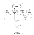
 図1は、本発明の実施の形態1に係る太陽光発電システムを電源系統に連系させた電力系統を示す図である。電力会社の電源系統21から買電した電気が分電盤25に供給されると共に、太陽光パネル22からパワーコンディショナ23を介して自家発電した電気が供給される。また、パワーコンディショナ23は電力メータ24に接続され、太陽光発電による余剰電力があった場合、逆潮流して売電することが可能である。
Embodiment 1 FIG.
FIG. 1 is a diagram showing a power system in which a photovoltaic power generation system according to Embodiment 1 of the present invention is linked to a power supply system. The electricity purchased from the power supply system 21 of the electric power company is supplied to the distribution board 25, and the electricity generated from the solar panel 22 through the power conditioner 23 is supplied. Moreover, the power conditioner 23 is connected to the power meter 24, and when there is surplus power by solar power generation, it is possible to sell power by flowing backward.
 図2は、実施の形態1に係る給湯機運転管理システムの構成例を示すブロック図である。給湯機運転管理システム100は、給湯機運転管理装置1と、ホームゲートウェイ3とを備える。ホームゲートウェイ3は、住居1~Nを所定地域内の集合体として構成する合計N戸の一戸建て住宅に、それぞれ設置される。なお、本実施の形態では、2以上の住居を想定しているが、N=1であってもよい。給湯機運転管理装置1と各ホームゲートウェイ3とは、有線方式または無線方式、あるいは、これらを組み合わせた方式の通信ネットワーク2を介して接続されている。なお、通信ネットワーク2は、公衆の用に供される共用通信回線や独自の専用通信回線などでもよく、それらを組み合わせたものでもよい。 FIG. 2 is a block diagram illustrating a configuration example of the water heater operation management system according to the first embodiment. The water heater operation management system 100 includes a water heater operation management device 1 and a home gateway 3. The home gateway 3 is installed in each of a total of N single-family houses that constitute the houses 1 to N as aggregates in a predetermined area. In the present embodiment, two or more residences are assumed, but N = 1 may be used. The hot water heater operation management device 1 and each home gateway 3 are connected via a communication network 2 of a wired system, a wireless system, or a combination of these. The communication network 2 may be a shared communication line provided for public use, an original dedicated communication line, or the like, or a combination thereof.
 図1に示す太陽光パネル22、パワーコンディショナ23、電力メータ24、分電盤25は、所定地域内の集合体に接続されて、集合体で共有する構成としてもよいし、各住居(N戸)にそれぞれ1組ずつ接続されていてもよい。また、太陽光発電システムを備える住居と備えない住居が混在する集合体であってもよい。 The solar panel 22, the power conditioner 23, the power meter 24, and the distribution board 25 shown in FIG. 1 may be connected to an assembly in a predetermined area and shared by the assembly, or each residence (N One set may be connected to each door. Moreover, the aggregate | assembly which the residence provided with a solar power generation system and the residence which is not provided may be sufficient.
 図2の例では、各住居には、所定の機能を居住者に提供する電気機器として、テレビ5、空調機6、照明7および給湯機8が設置され、各電気機器にはそれぞれ通信機器4が接続されている。各通信機器4は、宅内ネットワークを介してホームゲートウェイ3に接続されている。 In the example of FIG. 2, a television 5, an air conditioner 6, a lighting 7, and a water heater 8 are installed in each dwelling as electric devices that provide a resident with a predetermined function, and each electric device has a communication device 4. Is connected. Each communication device 4 is connected to the home gateway 3 via a home network.
 ホームゲートウェイ3は、同じ住居に設置されたテレビ5、空調機6、照明7および給湯機8の稼働状態を示す稼働データを各電気機器の通信機器4から取得して、各電気機器の稼働状態を監視する。各住居に設置される電気機器は、これに限らず、例えば、換気扇、IHクッキングヒータ、電子レンジ、冷蔵庫、炊飯器、パソコン、ルームエアコン、床暖房、電動窓、電動ブラインドなど、宅内ネットワークを介して監視・制御ができる機器であればよい。 The home gateway 3 acquires operation data indicating the operation state of the television 5, the air conditioner 6, the lighting 7, and the water heater 8 installed in the same residence from the communication device 4 of each electric device, and the operation state of each electric device. To monitor. The electrical equipment installed in each residence is not limited to this, for example, via a home network such as a ventilation fan, IH cooking heater, microwave oven, refrigerator, rice cooker, personal computer, room air conditioner, floor heating, electric window, electric blind, etc. Any device that can be monitored and controlled may be used.
 エネルギー計測装置9は、宅内ネットワークに接続されており、各住居のブレーカに分岐回路毎に取り付けられたCTセンサなどから、宅内ネットワーク接続された電気機器の消費電力だけでなく、宅内ネットワーク接続されていない電気機器の消費電力を含む、各住居全体の消費電力を示す消費電力データを収集する。また、エネルギー計測装置9は、太陽光発電による発電電力を示す発電電力データも合わせて収集する。 The energy measuring device 9 is connected to the home network, and is connected not only to the power consumption of the electrical equipment connected to the home network but also to the home network from a CT sensor or the like attached to each breaker in each residence. Collect power consumption data showing the power consumption of each entire residence, including the power consumption of no electrical equipment. In addition, the energy measuring device 9 also collects generated power data indicating the power generated by solar power generation.
 ホームゲートウェイ3は、エネルギー計測装置9の通信機器4から消費電力データおよび発電電力データを取得する。ホームゲートウェイ3は、各電気機器の通信機器4から取得した稼働データと、エネルギー計測装置9の通信機器4から取得した消費電力データおよび発電電力データ(以下、稼働データ、消費電力データおよび発電電力データを総称して電気機器動作データという)に収集された日時を示す収集日時を付与して給湯機運転管理装置1に送信する。 The home gateway 3 acquires power consumption data and generated power data from the communication device 4 of the energy measuring device 9. The home gateway 3 includes the operation data acquired from the communication device 4 of each electric device and the power consumption data and generated power data (hereinafter, operation data, power consumption data and generated power data) acquired from the communication device 4 of the energy measuring device 9. (Collectively referred to as “electric device operation data”), the collected date and time indicating the collected date and time is assigned and transmitted to the water heater operation management device 1.
 給湯機運転管理装置1は、各住居に設置される各ホームゲートウェイ3から取得する電気機器動作データと外部から取得する気象情報とに基づいて、各住居に設置された給湯機8の運転スケジュールを決定する。給湯機運転管理装置1は、決定した運転スケジュールを示すスケジュール情報を対応する住居のホームゲートウェイ3に送信する。ホームゲートウェイ3は、給湯機運転管理装置1から受信したスケジュール情報に基づいて、給湯機8の沸き上げ運転を制御する。 The water heater operation management device 1 determines the operation schedule of the water heater 8 installed in each residence based on the electrical equipment operation data acquired from each home gateway 3 installed in each residence and the weather information acquired from the outside. decide. The water heater operation management device 1 transmits schedule information indicating the determined operation schedule to the home gateway 3 of the corresponding residence. The home gateway 3 controls the heating operation of the water heater 8 based on the schedule information received from the water heater operation management device 1.
 図3は、実施の形態1に係るホームゲートウェイの機能構成例を示す図である。ホームゲートウェイ3は、電力データ取得部31と、稼働データ取得部32と、ホームゲートウェイ通信部33と、給湯機制御部34とを備える。住居1~Nの各々に設置されるホームゲートウェイ3は同様の機能構成である。図3では、通信機器4を省略している。 FIG. 3 is a diagram illustrating a functional configuration example of the home gateway according to the first embodiment. Home gateway 3 includes a power data acquisition unit 31, an operation data acquisition unit 32, a home gateway communication unit 33, and a water heater control unit 34. The home gateway 3 installed in each of the residences 1 to N has the same functional configuration. In FIG. 3, the communication device 4 is omitted.
 電力データ取得部31は、エネルギー計測装置9から消費電力データおよび発電電力データを取得する。消費電力データは、例えば、宅内ネットワークに接続されているテレビ5、空調機6、照明7、給湯機8の消費電力を示すデータ、宅内ネットワークに接続されていないドライヤーや掃除機などの消費電力を示すデータなどである。 The power data acquisition unit 31 acquires power consumption data and generated power data from the energy measuring device 9. The power consumption data includes, for example, data indicating the power consumption of the TV 5, the air conditioner 6, the lighting 7, and the water heater 8 connected to the home network, and the power consumption of a dryer or a vacuum cleaner not connected to the home network. Data to be shown.
 稼働データ取得部32は、テレビ5、空調機6、照明7および給湯機8の各々の稼働状態を示す稼働データを取得する。稼働データは、例えば、テレビ5の電源のオン/オフや音量、空調機6の運転モードや設定温度、電源のオン/オフの予約時刻、給湯機8の貯湯量や設定温度などである。 The operation data acquisition unit 32 acquires operation data indicating the operation states of the television 5, the air conditioner 6, the lighting 7, and the water heater 8. The operation data includes, for example, the power on / off and volume of the television 5, the operation mode and set temperature of the air conditioner 6, the reserved time for turning on / off the power, the amount of hot water stored and the set temperature of the water heater 8, and the like.
 電力データ取得部31は、稼働データ取得部32により取得された稼働データに基づいて、あらかじめ記憶する単位時間あたりの消費電力を示す情報を用いて各電気機器の各々の消費電力を算出してもよい。また、電気機器が単独で自らの消費電力データをホームゲートウェイ3に送信できる場合は、エネルギー計測装置9を介する必要はない。 The power data acquisition unit 31 may calculate the power consumption of each electrical device using information indicating the power consumption per unit time stored in advance based on the operation data acquired by the operation data acquisition unit 32. Good. Further, when the electric device can transmit its own power consumption data to the home gateway 3 alone, it is not necessary to go through the energy measuring device 9.
 ホームゲートウェイ通信部33は、例えば通信ネットワーク2を介して給湯機運転管理装置1との間で各種データを授受する通信インタフェースであって、ホームゲートウェイ通信部33は、電力データ取得部31および稼働データ取得部32が取得した電気機器動作データを給湯機運転管理装置1に送信する。また、ホームゲートウェイ通信部33は、給湯機運転管理装置1からスケジュール情報を受信する。 The home gateway communication unit 33 is a communication interface that exchanges various data with the water heater operation management device 1 via the communication network 2, for example. The home gateway communication unit 33 includes the power data acquisition unit 31 and the operation data. The electric device operation data acquired by the acquisition unit 32 is transmitted to the water heater operation management device 1. In addition, the home gateway communication unit 33 receives schedule information from the water heater operation management device 1.
 給湯機制御部34は、ホームゲートウェイ通信部33が給湯機運転管理装置1から受信したスケジュール情報に基づいて、給湯機8に制御指示を送り、沸き上げ運転を制御する。 The water heater controller 34 sends a control instruction to the water heater 8 based on the schedule information received from the water heater operation management device 1 by the home gateway communication unit 33 to control the heating operation.
 図4は、実施の形態1に係る給湯機の一例を示す図である。図4の例では、給湯機8は、ヒートポンプ式加熱器801と貯湯タンク802が水流路803によって連通される。ヒートポンプ式加熱器801では、蒸発器814で空気中の熱を媒体が吸収し、圧縮器811で圧縮されてさらに高温になった媒体が放熱器812に送られる。水流路803を通る水は、循環ポンプ804によって放熱器812に導かれ、放熱器812の水冷媒熱交換作用により加熱されて、貯湯タンク802に供給される。ヒートポンプ式加熱器801の膨張弁813は、高圧になった媒体を膨張させて再び液化させる。 FIG. 4 is a diagram illustrating an example of a water heater according to the first embodiment. In the example of FIG. 4, the water heater 8 includes a heat pump heater 801 and a hot water storage tank 802 that communicate with each other through a water flow path 803. In the heat pump type heater 801, the medium absorbs heat in the air by the evaporator 814, and the medium that has been compressed by the compressor 811 and further heated is sent to the radiator 812. Water passing through the water flow path 803 is guided to the radiator 812 by the circulation pump 804, heated by the water / refrigerant heat exchange action of the radiator 812, and supplied to the hot water storage tank 802. The expansion valve 813 of the heat pump heater 801 expands the high-pressure medium and liquefies it again.
 貯湯タンク802の貯湯量は、貯湯センサ群821により監視される。貯湯センサ群821は、貯湯タンク802の貯湯量を示す情報をホームゲートウェイ3の稼働データ取得部32に送る。また、ヒートポンプ式加熱器801は、稼働状態を示す稼働データを稼働データ取得部32に送る。ヒートポンプ式加熱器801は、給湯機制御部34から送られる制御指示に従って、稼働する。 The amount of hot water stored in the hot water storage tank 802 is monitored by a hot water storage sensor group 821. The hot water storage sensor group 821 sends information indicating the amount of hot water stored in the hot water storage tank 802 to the operation data acquisition unit 32 of the home gateway 3. In addition, the heat pump heater 801 sends operation data indicating the operation state to the operation data acquisition unit 32. The heat pump heater 801 operates in accordance with a control instruction sent from the water heater controller 34.
 図5は、実施の形態1に係る給湯機の他の例を示す図である。図5の例では、給湯機8は、図4に示す給湯機8の構成に加えて、ラジエーター805、床暖房機器806、流路調整弁807を備える。図5に示す給湯機8は、ヒートポンプ式加熱器801で加熱された湯を、貯湯タンク802、または、ラジエーター805および床暖房機器806による暖房機器のいずれに循環させるかを流路調整弁807の開閉により操作する。つまり、図5に示す給湯機8は、給湯機能と暖房機能とを兼ね備える。流路調整弁807は、弁の向き、すなわち給湯機8の給湯または暖房のいずれで動作しているかを示す稼働データを稼働データ取得部32に送る。流路調整弁807は、給湯機制御部34から送られる制御指示に従って、開閉する。 FIG. 5 is a diagram illustrating another example of the water heater according to the first embodiment. In the example of FIG. 5, the water heater 8 includes a radiator 805, a floor heating device 806, and a flow path adjustment valve 807 in addition to the configuration of the water heater 8 shown in FIG. 4. The hot water heater 8 shown in FIG. 5 has a flow path adjustment valve 807 that determines whether the hot water heated by the heat pump heater 801 is circulated to the hot water storage tank 802 or the heating device by the radiator 805 and the floor heating device 806. Operate by opening and closing. That is, the water heater 8 shown in FIG. 5 has both a hot water supply function and a heating function. The flow path adjustment valve 807 sends operation data indicating the direction of the valve, that is, whether the hot water heater 8 is operating with hot water or heating, to the operation data acquisition unit 32. The flow path adjustment valve 807 opens and closes in accordance with a control instruction sent from the water heater controller 34.
 なお、図4および図5では、ヒートポンプ式加熱器801で湯を生成する例を示したが、これに限らず、電熱ヒーターなどを用いて湯を生成する給湯機など、電気で湯を生成する電気式給湯機であればよい。 4 and 5 show an example in which hot water is generated by the heat pump heater 801. However, the present invention is not limited thereto, and hot water is generated by electricity, such as a water heater that generates hot water using an electric heater or the like. Any electric water heater may be used.
 図6は、実施の形態1に係る給湯機運転管理装置の機能構成例を示す図である。給湯機運転管理装置1は、通信部11と、在宅判定部12と、気象情報取得部13と、記憶部14と、在宅予測部15と、余剰電力予測部16と、スケジュール決定部17とを備える。 FIG. 6 is a diagram illustrating a functional configuration example of the water heater operation management device according to the first embodiment. The water heater operation management device 1 includes a communication unit 11, a home determination unit 12, a weather information acquisition unit 13, a storage unit 14, a home prediction unit 15, a surplus power prediction unit 16, and a schedule determination unit 17. Prepare.
 通信部11は、例えば通信ネットワーク2を介して各種データを送受信する通信インタフェースである。通信部11は、各ホームゲートウェイ3から受信した電気機器動作データを記憶部14に記憶する。在宅判定部12は、記憶部14に蓄積された電気機器動作データに基づいて、所定の単位時間毎の各住居における居住者の在宅状態を判定し、判定した在宅状態を示す在宅状態データを生成する。 The communication unit 11 is a communication interface that transmits and receives various data via, for example, the communication network 2. The communication unit 11 stores the electrical device operation data received from each home gateway 3 in the storage unit 14. The home determination unit 12 determines the home state of the resident in each residence for each predetermined unit time based on the electrical device operation data stored in the storage unit 14, and generates home state data indicating the determined home state To do.
 例えば、着目する住居において、ある所定の単位時間内に消費電力の変化、各電気機器の稼働状態の変化があった場合、該所定の単位時間内の在宅状態は在宅と判定し、変化がなかった場合は不在と判定する。在宅判定部12は、生成した在宅状態データを記憶部14に記憶する。 For example, if there is a change in power consumption or a change in the operating state of each electrical device within a certain unit time at the residence of interest, the home state within the predetermined unit time is determined to be at home and there is no change. If it is found, it is determined to be absent. The home determination unit 12 stores the generated home state data in the storage unit 14.
 本実施の形態では、居住者が在宅しているか否かの在宅状態を「1」か「0」の値で示し、居住者が在宅している状態を「0」、居住者が不在の状態を「1」と表し、この値を状態値と呼ぶ。ここで所定の単位時間とは、在宅判定部12が在宅状態を判定する判定周期を示し、通信部11が電気機器動作データを受信する受信周期以上の時間間隔であればよい。例えば、判定周期を60分とし、電気機器動作データの受信周期を1分とする。この場合、在宅判定部12は、60周期分の電気機器動作データの推移に基づいて在宅状態を判定する。 In the present embodiment, the home status indicating whether the resident is at home is indicated by a value of “1” or “0”, the resident status is “0”, and the resident status is absent. Is represented as “1”, and this value is referred to as a state value. Here, the predetermined unit time indicates a determination cycle in which the home determination unit 12 determines the home state, and may be a time interval that is equal to or longer than a reception cycle in which the communication unit 11 receives the electric device operation data. For example, the determination cycle is 60 minutes, and the electrical device operation data reception cycle is 1 minute. In this case, the home determination unit 12 determines the home state based on the transition of the electrical equipment operation data for 60 cycles.
 本実施の形態では、エネルギー計測装置9は電気機器の消費電力データを収集し、給湯機運転管理装置1は、これを在宅状態の判定に用いる。しかし、これに限らず、エネルギー計測装置9はガスや水道などの使用量データを収集し、給湯機運転管理装置1は、これを在宅状態の判定に用いてもよい。 In the present embodiment, the energy measuring device 9 collects power consumption data of the electrical equipment, and the water heater operation management device 1 uses this to determine the home state. However, the present invention is not limited to this, and the energy measuring device 9 may collect usage data such as gas and water, and the water heater operation management device 1 may use this for determination of the home state.
 気象情報取得部13は、通信部11を介して各住居の所在地を含む地域の過去、現在および将来の気象情報を取得する。気象情報は、例えば、屋外の気温、湿度、天気などである。これらの取得した気象情報は、記憶部14に記憶され、データが蓄積される。 The weather information acquisition unit 13 acquires past, current and future weather information of the area including the location of each residence via the communication unit 11. The weather information is, for example, outdoor temperature, humidity, weather, and the like. The acquired weather information is stored in the storage unit 14 and data is accumulated.
 記憶部14は、ホームゲートウェイ3から受信した電気機器動作データと、在宅判定部12が生成した在宅状態データと、気象情報取得部13が取得した気象情報とを記憶する。さらに、記憶部14は、インターネットや標準電波の送信局などから取得した、年月日時分秒および曜日を含む日時を示す日時データを記憶しており、電気機器動作データの収集日時と対応付けられている。 The storage unit 14 stores the electrical equipment operation data received from the home gateway 3, the home state data generated by the home determination unit 12, and the weather information acquired by the weather information acquisition unit 13. Furthermore, the storage unit 14 stores date / time data indicating date / time including year / month / day / hour / minute / second and day of the week obtained from the Internet or a standard radio wave transmission station, and is associated with the collection date / time of the electrical equipment operation data. ing.
 図7は、実施の形態1に係る稼働データの一例を示す図である。稼働データは、収集された日時を示す収集日時と、電気機器の種別を示す機器種別と、該電気機器の稼働状態を示す状態1、状態2および状態3とを含んでいる。例えば、テレビの状態1は電源のオン/オフを示し、状態2は設定された音量を示し、状態3は選択された視聴チャンネルを示す。 FIG. 7 is a diagram illustrating an example of operation data according to the first embodiment. The operation data includes a collection date and time indicating the collected date and time, a device type indicating the type of the electric device, and states 1, 2 and 3 indicating the operation state of the electric device. For example, state 1 of the television indicates power on / off, state 2 indicates the set volume, and state 3 indicates the selected viewing channel.
 在宅判定部12は、所定の単位時間内の稼働データを参照し、少なくともいずれかの電気機器の状態1、状態2および状態3に変化があった場合、該所定の単位時間内の在宅状態は在宅と判定する。なお、稼働データが示す電気機器の稼働状態は3つに限らず1つ以上であればよい。 The home determination unit 12 refers to the operation data within a predetermined unit time, and when there is a change in the state 1, the state 2 and the state 3 of at least one of the electrical devices, the home state within the predetermined unit time is Determined to be at home. In addition, the operation state of the electrical equipment indicated by the operation data is not limited to three, and may be one or more.
 在宅予測部15は、記憶部14の日時データ、気象情報および在宅状態データに基づいて、各住居の将来の在宅状態を予測し、予測した在宅状態を示す予測在宅状態データを生成する。なお、在宅予測部15が在宅状態データのみに基づいて、各住居の将来の在宅状態を予測してもよい。 The home prediction unit 15 predicts the future home state of each residence based on the date / time data, weather information, and home state data stored in the storage unit 14, and generates predicted home state data indicating the predicted home state. The home prediction unit 15 may predict the future home state of each residence based only on the home state data.
 余剰電力予測部16は、記憶部14の日時データおよび気象情報と、電気機器動作データに含まれる消費電力データおよび発電電力データとに基づいて、各住居の将来の余剰電力を予測し、予測した余剰電力(以下、予測余剰電力という)の値を示す予測余剰電力データを生成する。 The surplus power prediction unit 16 predicts and predicts the future surplus power of each residence based on the date / time data and weather information in the storage unit 14 and the power consumption data and the generated power data included in the electrical equipment operation data. Predicted surplus power data indicating the value of surplus power (hereinafter referred to as predicted surplus power) is generated.
 スケジュール決定部17は、在宅予測部15により生成された予測在宅状態データと余剰電力予測部16により生成された予測余剰電力データとに基づいて、各住居に設置された給湯機の沸き上げ運転を行う運転スケジュールを決定し、決定した運転スケジュールを示すスケジュール情報を生成する。 Based on the predicted home state data generated by the home prediction unit 15 and the predicted surplus power data generated by the surplus power prediction unit 16, the schedule determination unit 17 performs the heating operation of the water heater installed in each residence. An operation schedule to be performed is determined, and schedule information indicating the determined operation schedule is generated.
 通信部11は、スケジュール決定部17により生成されたスケジュール情報を、対応する住居のホームゲートウェイ3に送信する。このようにして、給湯機運転管理装置1は、各住居の給湯機8が沸き上げ運転を行う時間帯を管理する。 The communication unit 11 transmits the schedule information generated by the schedule determination unit 17 to the home gateway 3 of the corresponding residence. In this way, the water heater operation management device 1 manages the time period during which the water heater 8 in each residence performs the boiling operation.
 次に、本実施の形態に係る給湯機運転管理システム100が実行する各処理について説明する。各処理は、予め定められた周期で実行される。ホームゲートウェイ3は、「電気機器動作データ収集処理」を実行する。 Next, each process executed by the water heater operation management system 100 according to the present embodiment will be described. Each process is executed at a predetermined cycle. The home gateway 3 executes “electric equipment operation data collection processing”.
(電気機器動作データ収集処理)
 図8は、実施の形態1に係る電気機器動作データ収集処理の動作の一例を示すフローチャートである。ホームゲートウェイ3の稼働データ取得部32は、テレビ5、空調機6、照明7、給湯機8のそれぞれから、稼働データを取得する(ステップS11)。電力データ取得部31は、エネルギー計測装置9から、消費電力データおよび発電電力データを取得する(ステップS12)。
(Electrical equipment operation data collection processing)
FIG. 8 is a flowchart showing an example of the operation of the electrical equipment operation data collection process according to the first embodiment. The operation data acquisition unit 32 of the home gateway 3 acquires operation data from each of the television 5, the air conditioner 6, the lighting 7, and the water heater 8 (step S11). The power data acquisition unit 31 acquires power consumption data and generated power data from the energy measuring device 9 (step S12).
 ホームゲートウェイ通信部33は、稼働データ取得部32および電力データ取得部31が取得した稼働データ、消費電力データおよび発電電力データを電気機器動作データとして、通信ネットワーク2を介して給湯機運転管理装置1に送信し(ステップS13)、処理を終了する。 The home gateway communication unit 33 uses the operation data, power consumption data, and generated power data acquired by the operation data acquisition unit 32 and the power data acquisition unit 31 as electrical device operation data via the communication network 2. (Step S13), and the process ends.
 ホームゲートウェイ3が電気機器動作データ収集処理を実行するタイミングは、例えば前述のように1分周期とする。しかし、これに限らず、判定周期より短い周期であればよい。また、電気機器動作データは、ステップS13で逐次送信されることに代えて、例えば、ホームゲートウェイ3に記憶部を設け、1日などの一定期間分の電気機器動作データを記憶してもよい。この場合、ホームゲートウェイ通信部33が一定期間分の電気機器動作データを一単位としてまとめて給湯機運転管理装置1に送信する。また、必要に応じて一定期間内の値を平均化する処理、積算する処理などを行ってもよい。 The timing at which the home gateway 3 executes the electrical equipment operation data collection process is, for example, 1 minute as described above. However, the present invention is not limited to this, and any period shorter than the determination period may be used. In addition, instead of sequentially transmitting the electric device operation data in step S13, for example, a storage unit may be provided in the home gateway 3 to store electric device operation data for a certain period such as one day. In this case, the home gateway communication unit 33 collects the electric device operation data for a certain period as a unit and transmits it to the water heater operation management device 1. Moreover, you may perform the process which averages the value within a fixed period, the process which integrates, etc. as needed.
 給湯機運転管理装置1は、「在宅状態判定処理」、「在宅状態予測処理」、「気象情報取得処理」、「余剰電力予測処理」および「運転スケジュール決定処理」を実行する。 The hot water heater operation management device 1 executes “at-home state determination processing”, “at-home state prediction processing”, “weather information acquisition processing”, “surplus power prediction processing”, and “operation schedule determination processing”.
(在宅状態判定処理)
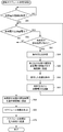
 図9は、実施の形態1に係る在宅状態判定処理の動作の一例を示すフローチャートである。給湯機運転管理装置1の在宅判定部12は、直前の1判定周期分の電気機器動作データを記憶部14から読み出す(ステップS21)。在宅判定部12では、直前の1判定周期分の電気機器動作データを参照し、テレビ5の稼働状態に変化があったか否かを判定する(ステップS22)。
(Home status determination process)
FIG. 9 is a flowchart illustrating an example of the operation of the home state determination process according to the first embodiment. The at-home determination unit 12 of the water heater operation management device 1 reads out the electrical device operation data for the immediately preceding determination cycle from the storage unit 14 (step S21). The at-home determination unit 12 determines whether or not there has been a change in the operating state of the television 5 by referring to the electrical device operation data for the immediately preceding one determination cycle (step S22).
 テレビ5の稼働状態に変化があった場合(ステップS22;Yes)、在宅判定部12は、居住者が在宅していると判定し、在宅状態データの該時間帯の状態値を「0」に設定し(ステップS27)、処理を終了する。テレビ5の稼働状態に変化がない場合(ステップS22;No)、在宅判定部12は、直前の1判定周期分の電気機器動作データを参照し、空調機6の稼働状態に変化があったか否かを判定する(ステップS23)。 When there is a change in the operating state of the television 5 (step S22; Yes), the home determination unit 12 determines that the resident is at home and sets the state value of the time zone of the home state data to “0”. Set (step S27), the process is terminated. When there is no change in the operating state of the television 5 (step S22; No), the at-home determination unit 12 refers to the electrical device operation data for the immediately preceding one determination cycle, and whether or not the operating state of the air conditioner 6 has changed. Is determined (step S23).
 空調機6の稼働状態に変化があった場合(ステップS23;Yes)、在宅判定部12は、居住者が在宅していると判定し、在宅状態データの該時間帯の状態値を「0」に設定し(ステップS27)、処理を終了する。空調機6の稼働状態に変化がない場合(ステップS23;No)、在宅判定部12は、直前の1判定周期分の電気機器動作データを参照し、照明7の稼働状態に変化があったか否かを判定する(ステップS24)。 When there is a change in the operating state of the air conditioner 6 (step S23; Yes), the home determination unit 12 determines that the resident is at home and sets the state value of the time zone of the home state data to “0”. (Step S27), and the process ends. When there is no change in the operating state of the air conditioner 6 (step S23; No), the at-home determination unit 12 refers to the electrical device operation data for the immediately preceding one determination cycle, and whether or not the operating state of the lighting 7 has changed. Is determined (step S24).
 照明7の稼働状態に変化があった場合(ステップS24;Yes)、在宅判定部12は、居住者が在宅していると判定し、在宅状態データの該時間帯の状態値を「0」に設定し(ステップS27)、処理を終了する。照明7の稼働状態に変化がない場合(ステップS24;No)、在宅判定部12は、直前の1判定周期分の電気機器動作データを参照し、給湯機8の稼働状態に変化があったか否かを判定する(ステップS25)。 When there is a change in the operating state of the lighting 7 (step S24; Yes), the home determination unit 12 determines that the resident is at home and sets the state value of the time zone of the home state data to “0”. Set (step S27), the process is terminated. When there is no change in the operating state of the lighting 7 (step S24; No), the at-home determination unit 12 refers to the electrical device operation data for one immediately preceding determination cycle, and whether or not the operating state of the water heater 8 has changed. Is determined (step S25).
 給湯機8の稼働状態に変化があった場合(ステップS25;Yes)、在宅判定部12は、居住者が在宅していると判定し、在宅状態データの該時間帯の状態値を「0」に設定し(ステップS27)、処理を終了する。給湯機8の稼働状態に変化がない場合(ステップS25;No)、つまり、宅内ネットワークに接続されているすべての電気機器の稼働状態に変化がない場合、在宅判定部12は、直前の1判定周期分の電気機器動作データを参照し、住居全体の消費電力量もしくは分岐回路毎の消費電力量に変化があったか否かを判定する(ステップS26)。これにより、宅内ネットワークに接続されておらず、ホームゲートウェイ3で稼働データを収集できない電気機器の稼働状態の変化を検出することができる。 When there is a change in the operating state of the water heater 8 (step S25; Yes), the home determination unit 12 determines that the resident is at home and sets the state value of the time zone of the home state data to “0”. (Step S27), and the process ends. When there is no change in the operating state of the water heater 8 (step S25; No), that is, when there is no change in the operating state of all the electrical devices connected to the home network, the home determination unit 12 determines the immediately preceding 1 determination. It is determined whether or not there has been a change in the power consumption of the entire residence or the power consumption of each branch circuit with reference to the electrical equipment operation data for the period (step S26). As a result, it is possible to detect a change in the operating state of an electrical device that is not connected to the home network and cannot collect operating data at the home gateway 3.
 住居全体の消費電力量もしくは分岐回路毎の消費電力量に変化があった場合(ステップS26;Yes)、在宅判定部12は、居住者が在宅していると判定し、在宅状態データの該時間帯の状態値を「0」に設定し(ステップS27)、処理を終了する。住居全体の消費電力量もしくは分岐回路毎の消費電力量に変化がなかった場合(ステップS26;No)、在宅判定部12は、居住者が不在であると判定し、在宅状態データの該時間帯の状態値を「1」に設定し(ステップS28)、処理を終了する。 When there is a change in the power consumption of the entire residence or the power consumption of each branch circuit (step S26; Yes), the home determination unit 12 determines that the resident is at home, and the time of the home status data The band status value is set to “0” (step S27), and the process is terminated. When there is no change in the power consumption of the entire residence or the power consumption of each branch circuit (step S26; No), the home determination unit 12 determines that the resident is absent, and the time zone of the home status data Is set to “1” (step S28), and the process ends.
 給湯機運転管理装置1が在宅状態判定処理を実行するタイミングは、例えば前述のように60分周期とする。しかし、これに限らず、電気機器動作データの受信周期より長い周期であればよい。 The timing at which the hot water heater operation management device 1 executes the at-home state determination process is, for example, 60 minutes as described above. However, the present invention is not limited to this, and a period longer than the reception period of the electric device operation data may be used.
 なお、ステップS22~S25で在宅状態を判定する材料となる対象の電気機器は、随時変更することが可能である。例えば、帰宅した際に室内が適度な温度になるよう在宅前から空調機6の運転が開始するよう予約時刻が設定されている場合などに、あらかじめ、在宅状態を判定する材料となる対象の電気機器から空調機6を外すことで、不在中に動作される電気機器の稼働状態の変化によって、誤った在宅状態が判定されることを防止することができる。 It should be noted that the target electrical device that is the material for determining the home state in steps S22 to S25 can be changed at any time. For example, when the reservation time is set so that the operation of the air conditioner 6 starts before the home so that the room is at a suitable temperature when returning home, the target electrical as a material for determining the home state is set in advance. By removing the air conditioner 6 from the device, it is possible to prevent an erroneous home state from being determined due to a change in the operating state of the electrical device that is operated during the absence.
 また、ステップS26で判定される消費電力量についても同様に、対象の分岐回路を随時変更することが可能である。これにより、不在中に動作される電気機器の稼働状態の変化によって、誤った在宅状態が判定されることを防止することができる。 Similarly, for the power consumption determined in step S26, the target branch circuit can be changed as needed. Accordingly, it is possible to prevent an erroneous home state from being determined due to a change in the operating state of an electrical device that is operated during the absence.
(在宅状態予測処理)
 図10は、実施の形態1に係る在宅状態予測処理の動作の一例を示すフローチャートである。給湯機運転管理装置1の記憶部14は、24時間分の在宅状態データをまとめて、日別在宅状態データとして記憶する。在宅予測部15は、記憶部14から、直近の所定の日数分の日別在宅状態データのうち、運転スケジュールを設定する日と同一の日時や、曜日、気象など所定の条件に当てはまる日別在宅状態データを読み出す(ステップS31)。
(Home status prediction process)
FIG. 10 is a flowchart illustrating an example of the home state prediction process according to the first embodiment. The storage unit 14 of the water heater operation management device 1 collects the home state data for 24 hours and stores it as daily home state data. The home prediction unit 15 from the storage unit 14 out of the daily home state data for the most recent predetermined number of days, homes by day that meet predetermined conditions such as the same date and time, day of the week, weather, etc. Status data is read (step S31).
 図11は、実施の形態1に係る日別在宅状態データの一例を示す図である。日別在宅状態データは、判定日と1時間ごとの判定時刻と判定時刻ごとの状態値が含まれる。図11の例では、9時から22時まで不在である。 FIG. 11 is a diagram illustrating an example of daily home status data according to the first embodiment. The daily home status data includes a determination date, a determination time for each hour, and a state value for each determination time. In the example of FIG. 11, it is absent from 9:00 to 22:00.
 在宅予測部15は、読み出した日別在宅状態データの状態値の平均(平均状態値)を、判定時刻ごとに算出する(ステップS32)。在宅予測部15は、平均状態値と、あらかじめ設定された閾値とを比較する(ステップS33)。 The home prediction unit 15 calculates the average (average state value) of the state values of the read daily home state data for each determination time (step S32). The home prediction unit 15 compares the average state value with a preset threshold value (step S33).
 平均状態値が閾値よりも大きい場合(ステップS33;Yes)、在宅予測部15は、予測在宅状態データの該時刻の状態値を「1」に設定し(ステップS34)、処理を終了する。平均状態値が閾値よりも小さい場合(ステップS33;No)、予在宅予測部15は、測在宅状態データの該時刻の状態値を「0」に設定し(ステップS35)、処理を終了する。 When the average state value is larger than the threshold (step S33; Yes), the home prediction unit 15 sets the state value at the time of the predicted home state data to “1” (step S34), and ends the process. When the average state value is smaller than the threshold value (step S33; No), the pre-existing home prediction unit 15 sets the time state value of the measured home state data to “0” (step S35), and ends the process.
 給湯機運転管理装置1は、この処理(ステップS31~ステップS35)を、すべての住居の日別在宅状態データについて実行する。 The water heater operation management device 1 executes this processing (steps S31 to S35) for the daily home status data of all the residences.
 具体的には、例えば、住居1の第四水曜日の朝7時~7時半の予測在宅状態データを同じ月の同じ曜日の在宅状態データに基づいて算出する場合、在宅予測部15は、直近21日(3週間)分の住居1の日別在宅状態データのうち、第一、第二、第三水曜日の朝7時~7時半の在宅状態データ3個を読み出す。第一水曜日の在宅状態データが状態値「1(不在)」、第二水曜日の在宅状態データが状態値「0(在宅)」、第三水曜日の在宅状態データが状態値「1(不在)」であった場合、平均状態値は「0.66…」となる。 Specifically, for example, when calculating the predicted home state data from 7 am to 7:30 in the morning of the fourth Wednesday of the residence 1 based on the home state data of the same day of the same month, the home prediction unit 15 Of the 21-day (three-week) home-at-home data for each day, three home-state data from 7 am to 7:30 am on the first, second and third Wednesdays are read out. The home status data on the first Wednesday is the status value “1 (absence)”, the home status data on the second Wednesday is the status value “0 (home)”, and the home status data on the third Wednesday is the status value “1 (absence)” In this case, the average state value is “0.66.
 ここで、閾値が「0.5」に設定されていた場合、在宅予測部15は、平均状態値が閾値より大きいので在宅状態を「不在」と予測し、予測在宅状態データの第四水曜日の朝7時~7時半の状態値を「1」に設定する。 Here, when the threshold is set to “0.5”, the home prediction unit 15 predicts the home state as “absent” because the average state value is larger than the threshold, and the predicted home state data on the fourth Wednesday Set the state value from 7 am to 7:30 in the morning to “1”.
 以上のように、運転スケジュールを設定する日と同条件の日時データを用いて予測在宅状態を予測することで、居住者の生活スケジュールを高精度に予測することができる。また、気象情報を用いて在宅状態を予測することで、予測精度をさらに高くすることができる。 As described above, it is possible to predict the resident's life schedule with high accuracy by predicting the predicted home state using the date and time data having the same conditions as the day for setting the driving schedule. Moreover, prediction accuracy can be further increased by predicting the home state using weather information.
 例えば、雨の予報が出されている6月6日の18時~18時半の予測在宅状態データを、雨が降った過去5日分の在宅状態データに基づいて算出する場合、在宅予測部15は、直近56日(8週間)分の住居Aの日別在宅状態データのうち、直近5日分の雨が降った6月5日、5月22日、5月21日、5月5日、4月30日の18時~18時半の在宅状態データ5個を読み出す。これらの在宅状態データがそれぞれ状態値「0」、状態値「0」、状態値「0」、状態値「1」、状態値「0」であった場合、平均状態値は「0.2」となる。 For example, when calculating the predicted home state data from 18:00 to 18:30 on June 6 when rain is forecasted based on the home state data for the past five days when it rained, 15 is June 5th, May 22nd, May 21st, May 5th when the latest 5 days of rain have fallen out of the daily home status data for residence A for 56 days (8 weeks). 5 home condition data from 18:00 to 18:30 on April 30 are read out. When these home status data are the status value “0”, the status value “0”, the status value “0”, the status value “1”, and the status value “0”, the average status value is “0.2”. It becomes.
 ここで、閾値が「0.5」に設定されていた場合、在宅予測部15は、平均状態値が閾値より小さいので在宅状態を「在宅」と予測し、予測在宅状態データの6月6日の18時~18時半の状態値を「0」に設定する。 Here, when the threshold is set to “0.5”, the home prediction unit 15 predicts the home state as “at home” because the average state value is smaller than the threshold, and June 6 of the predicted home state data The state value from 18:00 to 18:30 is set to “0”.
 在宅状態を予測するための閾値は、随時変更させることが可能であり、閾値を0.5よりも大きな値(例えば0.7)に設定して不在判定を厳しくしてもよいし、逆に閾値を0.5よりも小さな値(例えば0.3)に設定して不在と判定され易くしてもよい。例えば、判定対象のすべての時間帯で不在である場合にのみ予測在宅状態を不在判定としたいのであれば、閾値を1に設定すればよい。 The threshold for predicting the home status can be changed at any time, and the threshold may be set to a value larger than 0.5 (for example, 0.7) to make the absence determination stricter. The threshold value may be set to a value smaller than 0.5 (for example, 0.3) to make it easier to determine absence. For example, the threshold may be set to 1 if it is desired that the predicted home state is determined to be absent only when it is absent in all time zones to be determined.
 給湯機運転管理装置1の在宅予測部15は、例えば、運転スケジュールを設定する日の直前(例えば前日の23時)のタイミングで、各住居の翌日の在宅状態を予測する在宅状態予測処理を実行する。在宅予測部15が在宅状態予測処理を実行するタイミングは、記憶部14に必要なデータが揃ったタイミングでもよい。しかし、直前に在宅状態予測処理を実行した方が、予測在宅状態データをいったん記憶部14に保存する必要がなく、記憶部14のメモリ容量を減らすことができるといった利点がある。 The home prediction unit 15 of the water heater operation management device 1 executes, for example, a home state prediction process for predicting the home state on the next day of each residence at the timing immediately before the day when the operation schedule is set (for example, 23:00 on the previous day). To do. The timing at which the home prediction unit 15 executes the home state prediction process may be a timing at which necessary data is prepared in the storage unit 14. However, if the home state prediction process is executed immediately before, there is an advantage that the predicted home state data need not be temporarily stored in the storage unit 14 and the memory capacity of the storage unit 14 can be reduced.
 なお、本実施の形態では平均状態値を閾値と比較することで予測在宅状態を判別したが、平均を用いず、複数の状態値から「0」「1」の個数の多さ(多数決)により在宅状態を予測してもよい。 In the present embodiment, the predicted home state is determined by comparing the average state value with the threshold value, but the average is not used, and the number of “0” and “1” is determined from a plurality of state values (majority decision). You may predict a home state.
(余剰電力予測処理)
 図12は、実施の形態1に係る余剰電力予測処理の動作の一例を示すフローチャートである。給湯機運転管理装置1の余剰電力予測部16は、記憶部14から翌日の気象情報を読み出す(ステップS41)。
(Surplus power prediction process)
FIG. 12 is a flowchart illustrating an example of operation of surplus power prediction processing according to the first embodiment. The surplus power prediction unit 16 of the water heater operation management device 1 reads the weather information of the next day from the storage unit 14 (step S41).
 次に、余剰電力予測部16は、記憶部14が記憶する過去の気象情報から翌日の気象情報に類似する日を抽出する(ステップS42)。翌日の気象情報に類似する日とは、例えば、翌日の日照予測時間帯と過去の日照時間帯とが最も近い日である。 Next, the surplus power prediction unit 16 extracts a day similar to the weather information of the next day from the past weather information stored in the storage unit 14 (step S42). The day similar to the weather information of the next day is, for example, the day when the predicted sunshine time zone of the next day is the closest to the past sunshine time zone.
 余剰電力予測部16は、記憶部14から類似する日の各時間帯の消費電力データと発電電力データを読み出し(ステップS43)、読み出した消費電力データと発電電力データに基づいて、各時間帯の余剰電力を予測する(ステップS44)。余剰電力予測部16は、予測余剰電力の値を示す予測余剰電力データを生成し(ステップS45)、処理を終了する。 The surplus power predicting unit 16 reads the power consumption data and the generated power data for each time zone on a similar day from the storage unit 14 (step S43), and based on the read power consumption data and the generated power data for each time zone. Surplus power is predicted (step S44). The surplus power prediction unit 16 generates predicted surplus power data indicating the value of the predicted surplus power (step S45), and ends the process.
 給湯機運転管理装置1の余剰電力予測部16は、例えば、運転スケジュールを設定する直前(例えば前日の23時)のタイミングで、各住居の翌日の余剰電力を予測する余剰電力予測処理を実行する。各住居の時間帯毎の予測余剰電力の値は例えば、数1の計算式で算出される。 The surplus power prediction unit 16 of the water heater operation management device 1 executes, for example, surplus power prediction processing for predicting surplus power on the next day of each residence at the timing immediately before setting the operation schedule (for example, 23:00 on the previous day). . The value of the predicted surplus power for each time zone of each residence is calculated by, for example, the equation (1).
Figure JPOXMLDOC01-appb-M000001
 ここで、Psiはある時間帯における住居i(iは1~Nのいずれか)の予測余剰電力、Pgiは同一時間帯における住居iの発電電力、Pciは同一時間帯における住居iの消費電力、Pbiは同一時間帯が沸き上げ運転予約時間に含まれる場合のこの時間帯における給湯機8の消費電力を示し、いずれもステップS43において、記憶部14から読み出される。住居iが太陽光発電システムを備えていない場合、Pgiは常に0であり、時間帯によらずPsi=0となる。 Here, Psi is the predicted surplus power of residence i (i is any one of 1 to N) in a certain time zone, Pgi is the generated power of residence i in the same time zone, Pci is the power consumption of residence i in the same time zone, Pbi indicates the power consumption of the water heater 8 in this time zone when the same time zone is included in the heating operation reservation time, and both are read from the storage unit 14 in step S43. When the residence i does not have a solar power generation system, Pgi is always 0, and Psi = 0 regardless of the time zone.
 なお、過去の気象情報から翌日の気象情報に類似する日を抽出する方法は、所定の気象条件の最も近い日を選択する場合だけでなく、所定の気象条件の値が近い順に複数日(5日分など)を抽出してもよい。この場合、類似する複数日の平均値を取って予測余剰電力を算出するとよい。また、発電電力データは気象情報が類似する複数日の平均値を取り、消費電力データは曜日が一致した日の平均値を取る、といったように、予測余剰電力の算出方法は用途に合わせて異なってもよい。 In addition, the method of extracting the day similar to the weather information of the next day from the past weather information is not only for selecting the day closest to the predetermined weather condition, but also for multiple days (5 Day)) may be extracted. In this case, the predicted surplus power may be calculated by taking an average value of a plurality of similar days. In addition, the calculation method of predicted surplus power differs depending on the application, such as the average value for multiple days with similar weather information and the average value for the day with the same day of the week. May be.
(運転スケジュール決定処理1)
 図13は、実施の形態1に係る運転スケジュール決定処理の動作の一例を示すフローチャートである。給湯機運転管理装置1のスケジュール決定部17は、余剰電力予測処理で生成された予測余剰電力データに基づいて、時間帯毎に各住居の予測余剰電力Psiを加算し、集合体の予測余剰電力を算出する(ステップS51)。ただし、太陽光発電システムを集合体で共有する場合、集合体の予測余剰電力は、全住居のPsi総和ではなく、数2の計算式で算出される。
(Driving schedule determination process 1)
FIG. 13 is a flowchart illustrating an example of the operation of the operation schedule determination process according to the first embodiment. The schedule determination unit 17 of the water heater operation management device 1 adds the predicted surplus power Psi of each residence for each time zone based on the predicted surplus power data generated by the surplus power prediction process, and predicts the surplus power of the aggregate. Is calculated (step S51). However, when the photovoltaic power generation system is shared by the aggregate, the predicted surplus power of the aggregate is calculated not by the total Psi sum of all the residences but by the formula (2).
Figure JPOXMLDOC01-appb-M000002
 Pgは集合体で共有される太陽光発電システムの発電電力を示す。スケジュール決定部17は、集合体の予測余剰電力が給湯機8の沸き上げ運転による消費電力以上となる時間帯(以下、余剰電力発生時間帯という)があるか否かを判定する(ステップS52)。余剰電力発生時間帯がない場合(ステップS52;No)、スケジュール決定部17は、沸き上げ運転を割り当てられていない未設定の住居(全住居)の給湯機8の沸き上げ運転を通常の時間帯(夜間)に設定する(ステップS58)。 * Pg indicates the generated power of the solar power generation system shared by the aggregate. The schedule determination unit 17 determines whether or not there is a time zone in which the predicted surplus power of the aggregate is equal to or greater than the power consumption by the heating operation of the water heater 8 (hereinafter referred to as surplus power generation time zone) (step S52). . When there is no surplus power generation time zone (step S52; No), the schedule determination unit 17 performs the heating operation of the water heater 8 of an unset residence (all residences) to which the heating operation is not assigned. (Night) is set (step S58).
 余剰電力発生時間帯がある場合(ステップS52;Yes)、スケジュール決定部17は、在宅状態予測処理で生成された予測在宅状態データに基づいて、余剰電力発生時間帯に不在となる住居があるか否かを判定する(ステップS53)。 If there is a surplus power generation time zone (step S52; Yes), the schedule determination unit 17 determines whether there is a residence that is absent in the surplus power generation time zone based on the predicted home status data generated by the home status prediction process. It is determined whether or not (step S53).
 余剰電力発生時間帯に不在宅となる住居がある場合(ステップS53;Yes)、スケジュール決定部17は、該当する住居のうち、残湯量の多い順(沸き上げ湯量の少ない順)に優先順位を決定する(ステップS54)。スケジュール決定部17は、優先順位が最上位の住居の給湯機8の沸き上げ運転を余剰電力発生時間帯に設定する(ステップS55)。 When there is a residence that is not in the surplus power generation time zone (step S53; Yes), the schedule determination unit 17 gives priority to the corresponding residence in the order of the remaining hot water amount (in the order of the amount of boiling water). Determine (step S54). The schedule determination unit 17 sets the heating operation of the hot water heater 8 of the residence with the highest priority in the surplus power generation time zone (step S55).
 続いて、スケジュール決定部17は、給湯機8の沸き上げ運転を余剰電力発生時間帯に設定した住居を除外し(ステップS56)、余剰電力発生時間帯の予測余剰電力から給湯機8の沸き上げ運転に必要な消費電力を減算する(ステップS57)。処理はステップS52に戻り、余剰電力発生時間帯がなくなるか、余剰電力発生時間帯に不在宅となるすべての住居の給湯機8の沸き上げ運転が割り当てられ、余剰電力発生時間帯に不在となる住居がなくなるまで、ステップ52~ステップ57を繰り返す。 Then, the schedule determination part 17 excludes the residence which set the boiling operation of the water heater 8 to the surplus power generation time zone (step S56), and the water heater 8 is boiled from the predicted surplus power in the surplus power generation time zone. The power consumption necessary for operation is subtracted (step S57). The process returns to step S52, and the surplus power generation time period is exhausted, or the heating operation of the hot water heaters 8 of all the residences that are not in the surplus power generation time period is assigned, and the surplus power generation time period is absent. Repeat steps 52 to 57 until there are no more houses.
 余剰電力発生時間帯がなくなるか(ステップS52;No)、余剰電力発生時間帯に不在となる住居がなくなると(ステップS53;No)、スケジュール決定部17は、沸き上げ運転を割り当てられていない残りの未設定の住居の給湯機8の沸き上げ運転を通常の時間帯(夜間)に設定する(ステップS58)。 When there is no surplus power generation time zone (step S52; No), or when there are no residences that are absent in the surplus power generation time zone (step S53; No), the schedule determination unit 17 remains to which no boiling operation is assigned. Is set to the normal time zone (nighttime) (step S58).
 一方、余剰電力発生時間帯に不在宅となる住居がない場合(ステップS53;No)、スケジュール決定部17は、沸き上げ運転を割り当てられていない未設定の住居(全住居)の給湯機8の沸き上げ運転を通常の時間帯(夜間)に設定する(ステップS58)。このとき、余剰電力発生時間帯の予測余剰電力を例えば便宜的に0(ゼロ)に更新してもよい。 On the other hand, when there is no residence that is not at home in the surplus power generation time zone (step S53; No), the schedule determination unit 17 sets the hot water heater 8 of an unset residence (all residences) to which no heating operation is assigned. The boiling operation is set to a normal time zone (nighttime) (step S58). At this time, the predicted surplus power in the surplus power generation time zone may be updated to 0 (zero) for convenience, for example.
 スケジュール決定部17は、全住居の沸き上げ運転スケジュールを示すスケジュール情報を生成し(ステップS59)、通信部11は通信ネットワーク2を介してスケジュール情報を対応する住居のホームゲートウェイ3に送信し(ステップS60)、処理を終了する。 The schedule determination unit 17 generates schedule information indicating the heating operation schedule of all the houses (Step S59), and the communication unit 11 transmits the schedule information to the corresponding home gateway 3 via the communication network 2 (Step S59). S60), the process is terminated.
 各住居に設置されているホームゲートウェイ3のホームゲートウェイ通信部33は、通信ネットワーク2を介して、給湯機運転管理装置1から運転スケジュールを受信すると、給湯機制御部34に送信し、給湯機制御部34は、運転スケジュールに基づいて給湯機8の沸き上げ運転の開始時間および停止時間を制御する。 When the home gateway communication unit 33 of the home gateway 3 installed in each residence receives the operation schedule from the water heater operation management device 1 via the communication network 2, the home gateway communication unit 33 transmits the operation schedule to the water heater control unit 34 to control the water heater. The unit 34 controls the start time and stop time of the boiling operation of the water heater 8 based on the operation schedule.
 なお、ステップS54では残湯量の多い順(沸き上げ湯量の少ない順)に優先順位を決定しているが、これは湯切れの発生する確率が低い順に優先度を付けて、居住者の快適性を損なわないためである。優先順位を決定する方法は、例えば、各住居の消費電力量の少ない順など用途に合わせて変更してもよい。また、住居が1つの場合は、自動的にその住居が優先順位1位になる。 In step S54, priority is determined in descending order of the amount of remaining hot water (in order of increasing amount of boiling hot water). It is because it does not impair. The method for determining the priority order may be changed in accordance with the application, for example, in order of decreasing power consumption of each residence. Moreover, when there is one residence, the residence automatically becomes the first priority.
 給湯機運転管理装置1のスケジュール決定部17は、あらかじめ設定されたタイミングで、運転スケジュール決定処理を実行する。 The schedule determination unit 17 of the water heater operation management device 1 executes an operation schedule determination process at a preset timing.
 本実施の形態では、在宅状態予測処理で生成された予測在宅状態データに基づいて、余剰電力発生時間帯に不在となる住居があるか否かを判定しているが、これに限らない。例えば、運転スケジュールを設定する直前のタイミングで、各住居の翌日の余剰電力を予測する余剰電力予測処理を実行する場合には、在宅判定部12が生成したリアルタイムの在宅状態データに基づいて、不在となっている住居があるか否かを判定してもよい。この場合、給湯機運転管理装置1は、在宅予測部15を備えなくてもよい。 In the present embodiment, based on the predicted home state data generated in the home state prediction process, it is determined whether there is a residence that is absent during the surplus power generation time period, but is not limited thereto. For example, when executing surplus power prediction processing for predicting surplus power on the next day of each residence at the timing immediately before setting the operation schedule, the absence based on the real-time home status data generated by the home determination unit 12 It may be determined whether there is a residence. In this case, the water heater operation management device 1 may not include the home prediction unit 15.
 以上説明したように、本実施の形態1の給湯機運転管理システム100によれば、気象条件に応じて発電量が変化する発電システムが電源系統につながっている場合において、1または2以上の住居の電気式の給湯機の沸き上げ運転を最適なタイミングで行うことができ、蓄電池を用いる場合よりも低コストで余剰電力を有効活用し、電力の平準化を実現することができる。さらに、居住者の生活スケジュールを考慮し、給湯機で沸き上げたお湯の使用を必要としない時間帯を中心に給湯機の沸き上げ運転時間帯を設定することで、居住者の快適性を保ちつつ、効率的に太陽光発電による余剰電力の活用を図ることができる。 As described above, according to the hot water heater operation management system 100 of the first embodiment, when the power generation system whose power generation amount changes according to the weather conditions is connected to the power supply system, one or more houses The electric water heater can be heated at an optimal timing, and surplus power can be effectively used at a lower cost than when a storage battery is used, and power leveling can be realized. Furthermore, in consideration of the resident's life schedule, the comfort of the resident can be maintained by setting the hot water heater's boiling operation time zone mainly during the time when the hot water heated by the hot water heater is not required. On the other hand, it is possible to efficiently utilize surplus power by solar power generation.
実施の形態2.
 双方向情報通信機能を備えた電力計であるスマートメーターを介して、電力会社(供給側)と住宅などの需要家(需要側)の双方向通信による情報伝達を実現させ、電力の価格情報が電力会社から需要家に送られ、需要家内のHEMS(Home Energy Management System)は、その価格情報に基づいて家電機器を最適に制御する、といったデマンドレスポンス技術がある。
Embodiment 2. FIG.
Through the smart meter, which is a wattmeter equipped with a two-way information communication function, information transmission through the two-way communication between the power company (supply side) and the consumer (demand side) such as a house is realized. There is a demand response technology in which a home energy management system (HEMS) sent from an electric power company to a consumer optimally controls home appliances based on the price information.
 一般的にデマンドレスポンスは電力使用のピーク時間の電気代を高くすることでピーク時間の電気使用量を抑制し、平準化する技術であるが、ここでは、余剰電力が発生する時間帯の電気使用量を増やすことで、余剰電力を活用することに用いる。実施の形態2では、実施の形態1の電力メータ24にスマートメーターを採用することで、よりリアルタイム性を持たせて太陽光発電による余剰電力の活用を図る。 In general, demand response is a technology that suppresses the level of electricity usage during peak hours by increasing the electricity bill during peak hours of electricity use, and here, it uses electricity during times when surplus power is generated. It is used to utilize surplus power by increasing the amount. In the second embodiment, a smart meter is employed as the power meter 24 of the first embodiment, thereby providing more real-time performance and utilizing surplus power by solar power generation.
 実施の形態2に係る給湯機運転管理システムの基本構成は、実施の形態1に係る給湯機運転管理システム100と同様である。実施の形態1と同一又は同等な構成部分については同一符号を付し、その説明を省略する。 The basic configuration of the water heater operation management system according to the second embodiment is the same as that of the water heater operation management system 100 according to the first embodiment. Constituent parts that are the same as or equivalent to those of the first embodiment are given the same reference numerals, and descriptions thereof are omitted.
 実施の形態2に係る給湯機運転管理装置1は、少なくとも通信部11、記憶部14およびスケジュール決定部17を備える。実施の形態2に係る運転スケジュール決定処理は、電力会社が太陽光発電による余剰電力が発生すると判定した時間帯に給湯機8などの家電機器を電力会社が自動で制御することを許可する契約をした契約住居を対象とする。例えば、契約の内容として、余剰電力を活用して電源系統の安定化に協力してもらうため、その時間帯の電気代を減額するなど、需要家にとってもメリットを享受できるようにすることが考えられる。本実施の形態では、住居1~Nに1以上の契約住居が含まれる。 The water heater operation management device 1 according to Embodiment 2 includes at least a communication unit 11, a storage unit 14, and a schedule determination unit 17. The operation schedule determination process according to the second embodiment is a contract that permits the electric power company to automatically control home appliances such as the water heater 8 during a time period when the electric power company determines that surplus power from solar power generation occurs. For contracted housing. For example, it may be possible to enjoy benefits for consumers, such as reducing the electricity bill for that time period in order to use the surplus power to cooperate in stabilizing the power system as the content of the contract. It is done. In the present embodiment, one or more contracted residences are included in the residences 1 to N.
(運転スケジュール決定処理2)
 図14は、実施の形態2に係る運転スケジュール決定処理の動作の一例を示すフローチャートである。電力会社は太陽光発電による電力供給量が増大して集合体の余剰電力が発生すると判定すると、該集合体の余剰電力が発生すると判定した時間帯と算出した余剰電力の値とを示す余剰電力情報をスマートメーターに送信する。スマートメーターは、受信した余剰電力情報を給湯機運転管理装置1の通信部11に送信する。
(Driving schedule determination process 2)
FIG. 14 is a flowchart illustrating an example of the operation of the operation schedule determination process according to the second embodiment. When the electric power company determines that the power supply amount by solar power generation increases and surplus power of the aggregate is generated, surplus power indicating the time zone determined that surplus power of the aggregate is generated and the calculated surplus power value Send information to the smart meter. The smart meter transmits the received surplus power information to the communication unit 11 of the water heater operation management device 1.
 給湯機運転管理装置1の通信部11は、余剰電力情報を受信しない場合(ステップS61;No)、ステップS61を繰り返し、余剰電力情報の受信を待機する。通信部11が余剰電力情報を受信した場合(ステップS61;Yes)、スケジュール決定部17は、余剰電力情報が示す時間帯の集合体の余剰電力が給湯機8の沸き上げ運転による消費電力以上となるか否かを判定する(ステップS62)。集合体の余剰電力が給湯機8の沸き上げ運転による消費電力以上とならない場合(ステップS62;No)、スケジュール決定部17は、沸き上げ運転を割り当てられていない未設定の住居(全住居)の給湯機8の沸き上げ運転を通常の時間帯(夜間)に設定する(ステップS68)。 When the surplus power information is not received (step S61; No), the communication unit 11 of the water heater operation management device 1 repeats step S61 and waits for the surplus power information to be received. When the communication unit 11 receives surplus power information (step S61; Yes), the schedule determination unit 17 determines that the surplus power of the aggregate in the time period indicated by the surplus power information is equal to or greater than the power consumption due to the boiling operation of the water heater 8. It is determined whether or not (step S62). When the surplus power of the aggregate does not exceed the power consumption due to the boiling operation of the water heater 8 (step S62; No), the schedule determination unit 17 sets the unset residences (all residences) to which the boiling operation is not assigned. The boiling operation of the water heater 8 is set to a normal time zone (nighttime) (step S68).
 集合体の余剰電力が給湯機8の沸き上げ運転による消費電力以上となる場合(ステップS62;Yes)、スケジュール決定部17は、あらかじめ記憶部14に記憶しておいた契約住居を示す契約住居情報を参照し、給湯機8の沸き上げ運転時間が割り当てられていない未設定の契約住居があるか否かを判定する(ステップS63)。 When the surplus power of the aggregate is greater than or equal to the power consumed by the heating operation of the water heater 8 (step S62; Yes), the schedule determination unit 17 indicates the contract residence information indicating the contract residence stored in the storage unit 14 in advance. In step S63, it is determined whether or not there is an unset contract dwelling to which the heating operation time of the water heater 8 is not assigned.
 契約住居がある場合(ステップS63;Yes)、スケジュール決定部17は、契約住居のうち、該時間帯の消費電力が多い順に優先順位を決定する(ステップS64)。スケジュール決定部17は、優先順位が最上位の住居の給湯機8の沸き上げ運転を余剰電力情報が示す時間帯に設定する(ステップS65)。 When there is a contracted residence (step S63; Yes), the schedule determination unit 17 determines the priority order in descending order of power consumption in the time zone among the contracted residences (step S64). The schedule determination unit 17 sets the heating operation of the hot water heater 8 in the residence with the highest priority in the time zone indicated by the surplus power information (step S65).
 続いて、スケジュール決定部17は、給湯機8の沸き上げ運転を余剰電力情報が示す時間帯に設定した住居を除外し(ステップS66)、余剰電力情報が示す時間帯の余剰電力から給湯機8の沸き上げ運転に必要な消費電力を減算する(ステップS67)。処理はステップS62に戻り、集合体の余剰電力が給湯機8の沸き上げ運転による消費電力より小さくなるか、未設定の契約住居がなくなるまでステップ62~ステップ67を繰り返す。 Then, the schedule determination part 17 excludes the residence which set the boiling operation of the water heater 8 in the time slot | zone which surplus power information shows (step S66), and the water heater 8 is used from the surplus power of the time slot | zone which surplus power information shows. The power consumption required for the boiling operation is subtracted (step S67). The process returns to step S62, and steps 62 to 67 are repeated until the surplus power of the aggregate becomes smaller than the power consumption by the heating operation of the water heater 8 or there is no unset contracted residence.
 集合体の余剰電力が給湯機8の沸き上げ運転による消費電力より小さくなるか(ステップS62;No)、未設定の契約住居がなくなると(ステップS63;No)、スケジュール決定部17は、沸き上げ運転を割り当てられていない残りの未設定の住居の給湯機8の沸き上げ運転を通常の時間帯(夜間)に設定する(ステップS68)。このとき、余剰電力情報が示す時間帯の余剰電力を例えば便宜的に0(ゼロ)に更新してもよい。 When the surplus power of the aggregate is smaller than the power consumption by the heating operation of the water heater 8 (step S62; No), or when there is no unset contracted residence (step S63; No), the schedule determination unit 17 raises the water. The boiling operation of the remaining hot water heaters 8 in which the operation is not assigned is set to a normal time zone (nighttime) (step S68). At this time, the surplus power in the time zone indicated by the surplus power information may be updated to 0 (zero) for convenience, for example.
 スケジュール決定部17は、全住居の沸き上げ運転スケジュールを示すスケジュール情報を生成し(ステップS69)、通信部11は通信ネットワーク2を介してスケジュール情報を電力会社に送信し(ステップS70)、処理を終了する。 The schedule determination part 17 produces | generates the schedule information which shows the heating operation schedule of all the residences (step S69), and the communication part 11 transmits schedule information to an electric power company via the communication network 2 (step S70), and performs a process. finish.
 電力会社は、給湯機運転管理装置1から運転スケジュールを受信すると、運転スケジュールに基づいて契約住居の給湯機8の沸き上げ運転の開始時間および停止時間を制御する。 When the electric power company receives the operation schedule from the water heater operation management device 1, the electric power company controls the start time and stop time of the boiling operation of the water heater 8 in the contracted residence based on the operation schedule.
 なお、ステップS64では余剰電力情報が示す時間帯の消費電力が多い順に優先に優先順位を決定しているが、この時の消費電力は、ホームゲートウェイ3の電力データ取得部31が収集した該当時間におけるリアルタイムでの消費電力でもよいし、過去の消費電力データから予測した消費電力でも構わない。また、契約住居での該時間帯の電気代が減額となるメリットを享受しやすいように、例えば、給湯機運転管理装置1が在宅予測部15を備え、予測在宅状態データが「在宅」となっている契約住居を優先するといったように、用途に合わせて変更しても構わない。 In step S64, the priority order is determined with priority in descending order of power consumption in the time zone indicated by the surplus power information. The power consumption at this time corresponds to the corresponding time collected by the power data acquisition unit 31 of the home gateway 3. The power consumption in real time may be used, or the power consumption predicted from past power consumption data may be used. Further, in order to easily enjoy the merit of reducing the electricity bill in the contracted residence, for example, the water heater operation management device 1 includes the home prediction unit 15 and the predicted home state data becomes “at home”. You may change it according to the usage, such as giving priority to the contracted residence.
 以上説明したように、本実施の形態2の給湯機運転管理システムによると、スマートメーターによる電力会社と住宅との双方向通信機能を用いることで、よりリアルタイムに太陽光発電による余剰電力を活用することができる。これにより、電力会社の電源系統の安定化に寄与することができる。 As described above, according to the hot water heater operation management system of the second embodiment, the surplus power generated by photovoltaic power generation is utilized in real time by using the bidirectional communication function between the power company and the house using the smart meter. be able to. Thereby, it can contribute to stabilization of the power supply system of an electric power company.
 本実施の形態1および2について別々に説明したが、これらの組み合わせてもよい。また、本実施の形態1および2に係る再生可能エネルギーは、太陽光発電システム以外に風力発電、地熱発電などの手段を採用してもよい。 Although Embodiments 1 and 2 have been described separately, these may be combined. Further, the renewable energy according to the first and second embodiments may employ means such as wind power generation and geothermal power generation in addition to the solar power generation system.
 図15は、本発明の実施の形態に係る給湯機運転管理装置のハードウェア構成の一例を示すブロック図である。給湯機運転管理装置1は、図15に示すように、制御部81、主記憶部82、外部記憶部83、操作部84、表示部85および送受信部86を備える。主記憶部82、外部記憶部83、操作部84、表示部85および送受信部86はいずれも内部バス80を介して制御部81に接続されている。 FIG. 15 is a block diagram showing an example of a hardware configuration of the water heater operation management device according to the embodiment of the present invention. As shown in FIG. 15, the water heater operation management device 1 includes a control unit 81, a main storage unit 82, an external storage unit 83, an operation unit 84, a display unit 85, and a transmission / reception unit 86. The main storage unit 82, the external storage unit 83, the operation unit 84, the display unit 85, and the transmission / reception unit 86 are all connected to the control unit 81 via the internal bus 80.
 制御部81はCPU(Central Processing Unit)などから構成され、外部記憶部83に記憶されている制御プログラム89に従って、給湯機運転管理装置1の在宅判定部12、気象情報取得部13、余剰電力予測部16、在宅予測部15およびスケジュール決定部17の各処理を実行する。 The control unit 81 includes a CPU (Central Processing Unit) and the like, and according to a control program 89 stored in the external storage unit 83, the home determination unit 12, the weather information acquisition unit 13, the surplus power prediction of the water heater operation management device 1 Each process of the unit 16, the home prediction unit 15 and the schedule determination unit 17 is executed.
 主記憶部82はRAM(Random-Access Memory)などから構成され、外部記憶部83に記憶されている制御プログラム89をロードし、制御部81の作業領域として用いられる。 The main storage unit 82 is composed of a RAM (Random-Access Memory) or the like, loads a control program 89 stored in the external storage unit 83, and is used as a work area of the control unit 81.
 外部記憶部83は、フラッシュメモリ、ハードディスク、DVD-RAM、DVD-RWなどの不揮発性メモリから構成され、給湯機運転管理装置1の処理を制御部81に行わせるためのプログラムをあらかじめ記憶し、また、制御部81の指示に従って、このプログラムが記憶するデータを制御部81に供給し、制御部81から供給されたデータを記憶する。記憶部14は外部記憶部83に構成される。 The external storage unit 83 includes a nonvolatile memory such as a flash memory, a hard disk, a DVD-RAM, and a DVD-RW, and stores in advance a program for causing the control unit 81 to perform the processing of the water heater operation management device 1. Further, in accordance with an instruction from the control unit 81, the data stored in the program is supplied to the control unit 81, and the data supplied from the control unit 81 is stored. The storage unit 14 is configured in the external storage unit 83.
 操作部84は、キーボードおよびマウスなどのポインティングデバイスなどと、キーボードおよびポインティングデバイスなどを内部バス80に接続するインタフェース装置から構成されている。ユーザが給湯機運転管理装置1に直接情報を入力する場合は、操作部84を介して、入力された情報が制御部81に供給される。 The operation unit 84 includes a pointing device such as a keyboard and a mouse, and an interface device that connects the keyboard and the pointing device to the internal bus 80. When the user inputs information directly to the hot water heater operation management device 1, the input information is supplied to the control unit 81 via the operation unit 84.
 表示部85は、CRT(Cathode Ray Tube)またはLCD(Liquid Crystal Display)などから構成されている。表示部85は、ユーザが給湯機運転管理装置1に直接情報を入力する場合は、操作画面を表示する。 The display unit 85 includes a CRT (Cathode Ray Tube) or an LCD (Liquid Crystal Display). The display unit 85 displays an operation screen when the user inputs information directly to the water heater operation management device 1.
 送受信部86は、ネットワークに接続する網終端装置または無線通信装置、およびそれらと接続するシリアルインタフェースまたはLAN(Local Area Network)インタフェースから構成されている。送受信部86は、通信部11として機能する。 The transmission / reception unit 86 includes a network termination device or a wireless communication device connected to the network, and a serial interface or a LAN (Local Area Network) interface connected to them. The transmission / reception unit 86 functions as the communication unit 11.
 図6に示す給湯機運転管理装置1の通信部11、在宅判定部12、気象情報取得部13、記憶部14、在宅予測部15、余剰電力予測部16およびスケジュール決定部17の処理は、制御プログラム89が、制御部81、主記憶部82、外部記憶部83、操作部84、表示部85および送受信部86などを資源として用いて処理することによって実行する。 The processing of the communication unit 11, the home determination unit 12, the weather information acquisition unit 13, the storage unit 14, the home prediction unit 15, the surplus power prediction unit 16, and the schedule determination unit 17 of the water heater operation management device 1 illustrated in FIG. The program 89 is executed by processing using the control unit 81, the main storage unit 82, the external storage unit 83, the operation unit 84, the display unit 85, the transmission / reception unit 86, and the like as resources.
 その他、前記のハードウェア構成やフローチャートは一例であり、任意に変更および修正が可能である。 In addition, the hardware configuration and flowchart described above are merely examples, and can be arbitrarily changed and modified.
 制御部81、主記憶部82、外部記憶部83、操作部84、表示部85、送受信部86、内部バス80などから構成される給湯機運転管理装置1の処理を行う中心となる部分は、専用のシステムによらず、通常のコンピュータシステムを用いて実現可能である。例えば、前記の動作を実行するためのコンピュータプログラムを、コンピュータが読み取り可能な記録媒体(フレキシブルディスク、CD-ROM、DVD-ROMなど)に格納して配布し、当該コンピュータプログラムをコンピュータにインストールすることにより、前記の処理を実行する給湯機運転管理装置1を構成してもよい。また、インターネットなどの通信ネットワーク上のサーバ装置が有する記憶装置に当該コンピュータプログラムを格納しておき、通常のコンピュータシステムがダウンロードなどすることで給湯機運転管理装置1を構成してもよい。 The central part that performs the processing of the water heater operation management device 1 including the control unit 81, the main storage unit 82, the external storage unit 83, the operation unit 84, the display unit 85, the transmission / reception unit 86, the internal bus 80, etc. It can be realized by using a normal computer system regardless of a dedicated system. For example, a computer program for executing the above operation is stored and distributed in a computer-readable recording medium (flexible disk, CD-ROM, DVD-ROM, etc.), and the computer program is installed in the computer. Therefore, the water heater operation management device 1 that performs the above-described processing may be configured. Alternatively, the hot water heater operation management device 1 may be configured by storing the computer program in a storage device included in a server device on a communication network such as the Internet and downloading it by a normal computer system.
 また、給湯機運転管理装置1の機能を、OS(オペレーティングシステム)とアプリケーションプログラムの分担、またはOSとアプリケーションプログラムとの協働により実現する場合などには、アプリケーションプログラム部分のみを記録媒体や記憶装置に格納してもよい。 Further, when the functions of the water heater operation management device 1 are realized by sharing of an OS (operating system) and an application program, or by cooperation between the OS and the application program, only the application program portion is recorded on a recording medium or a storage device. May be stored.
 また、搬送波にコンピュータプログラムを重畳し、通信ネットワークを介して提供することも可能である。例えば、通信ネットワーク上の掲示板(BBS, Bulletin Board System)に前記コンピュータプログラムを掲示し、ネットワークを介して前記コンピュータプログラムを提供してもよい。そして、このコンピュータプログラムを起動し、OSの制御下で、他のアプリケーションプログラムと同様に実行することにより、前記の処理を実行できるように構成してもよい。 It is also possible to superimpose a computer program on a carrier wave and provide it via a communication network. For example, the computer program may be posted on a bulletin board (BBS, Bulletin Board System) on a communication network, and the computer program may be provided via the network. The computer program may be started and executed in the same manner as other application programs under the control of the OS, so that the above-described processing may be executed.
 本発明は、本発明の広義の精神と範囲を逸脱することなく、様々な実施の形態および変形が可能とされるものである。また、上述した実施の形態は、本発明を説明するためのものであり、本発明の範囲を限定するものではない。本発明の範囲は、実施の形態ではなく、特許請求の範囲によって示される。そして、特許請求の範囲内およびそれと同等の発明の意義の範囲内で施される様々な変形が、本発明の範囲内とみなされる。 The present invention is capable of various embodiments and modifications without departing from the broad spirit and scope of the present invention. The above-described embodiments are for explaining the present invention and do not limit the scope of the present invention. The scope of the present invention is shown not by the embodiments but by the claims. Various modifications within the scope of the claims and within the scope of the equivalent invention are considered to be within the scope of the present invention.
 1 給湯機運転管理装置、2 通信ネットワーク、3 ホームゲートウェイ、4 通信機器、5 テレビ、6 空調機、7 照明、8 給湯機、9 エネルギー計測装置、11 通信部、12 在宅判定部、13 気象情報取得部、14 記憶部、15 在宅予測部、16 余剰電力予測部、17 スケジュール決定部、21 電源系統、22 太陽光パネル、23 パワーコンディショナ、24 電力メータ、25 分電盤、31 電力データ取得部、32 稼働データ取得部、33 ホームゲートウェイ通信部、34 給湯機制御部、80 内部バス、81 制御部、82 主記憶部、83 外部記憶部、84 操作部、85 表示部、86 送受信部、89 制御プログラム、100 給湯機運転管理システム、801 ヒートポンプ式加熱器、802 貯湯タンク、803 水流路、804 循環ポンプ、805 ラジエーター、806 床暖房機器、807 流路調整弁、811 圧縮器、812 放熱器、813 膨張弁、814 蒸発器、821 貯湯センサ群。 1 Water heater operation management device, 2 communication network, 3 home gateway, 4 communication equipment, 5 TV, 6 air conditioner, 7 lighting, 8 water heater, 9 energy measuring device, 11 communication unit, 12 home determination unit, 13 weather information Acquisition unit, 14 storage unit, 15 home prediction unit, 16 surplus power prediction unit, 17 schedule determination unit, 21 power system, 22 solar panel, 23 power conditioner, 24 power meter, 25 distribution board, 31 power data acquisition Unit, 32 operation data acquisition unit, 33 home gateway communication unit, 34 water heater control unit, 80 internal bus, 81 control unit, 82 main storage unit, 83 external storage unit, 84 operation unit, 85 display unit, 86 transmission / reception unit, 89 control program, 100 water heater operation management system, 801 heat pump Heater, 802 hot water storage tank, 803 water flow path, 804 circulation pump, 805 radiator, 806 floor heating equipment, 807 flow control valve, 811 compressor, 812 heat radiator, 813 expansion valve, 814 evaporator, 821 hot water storage sensor group .

Claims (8)

  1.  気象条件に応じて発電量が変化する発電システムが電源系統につながっている1または2以上の住居にそれぞれ設置された電気式の給湯機の運転を制御する給湯機運転管理装置であって、
     前記住居に設置された電気機器の稼働状態を示す稼働データを取得する稼働データ取得部と、
     前記住居の所在地を含む地域の気象情報を取得する気象情報取得部と、
     前記稼働データに基づいて前記住居の居住者が在宅であるか否かを判定し、判定した在宅状態を示す在宅状態データを生成する在宅判定部と、
     前記気象情報に基づいて前記発電システムの余剰電力を予測し、予測した余剰電力の発生する時間帯と余剰電力の値とを示す予測余剰電力データを生成する余剰電力予測部と、
     前記在宅状態データおよび前記予測余剰電力データに基づいて、前記住居の給湯機を運転させる運転スケジュールを決定し、決定した運転スケジュールを示す運転スケジュール情報を生成する運転スケジュール決定部と、
     を備える給湯機運転管理装置。
    A water heater operation management device that controls the operation of electric water heaters installed in one or two or more houses, each of which has a power generation system whose power generation amount changes according to weather conditions, connected to the power system.
    An operation data acquisition unit that acquires operation data indicating an operation state of the electrical equipment installed in the residence;
    A weather information acquisition unit for acquiring weather information of a region including the location of the residence;
    It is determined whether the resident of the residence is at home based on the operation data, and a home determination unit that generates home state data indicating the determined home state;
    Surplus power prediction unit that predicts surplus power of the power generation system based on the weather information, and generates predicted surplus power data indicating a time zone in which the predicted surplus power occurs and a value of surplus power;
    Based on the home status data and the predicted surplus power data, an operation schedule for determining the operation schedule for operating the hot water heater in the residence, and generating operation schedule information indicating the determined operation schedule; and
    A water heater operation management device comprising:
  2.  少なくとも前記在宅状態データに基づいて、前記予測余剰電力データが示す時間帯の前記住居の在宅状態を予測し、予測した在宅状態を示す予測在宅状態データを生成する在宅予測部をさらに備え、
     前記運転スケジュール決定部は、前記予測在宅状態データおよび前記予測余剰電力データに基づいて、前記運転スケジュールを決定し、前記運転スケジュール情報を生成する請求項1に記載の給湯機運転管理装置。
    Based on at least the home status data, further comprising a home prediction unit that predicts the home status of the residence in the time zone indicated by the predicted surplus power data, and generates predicted home status data indicating the predicted home status,
    The hot water heater operation management device according to claim 1, wherein the operation schedule determination unit determines the operation schedule based on the predicted home state data and the predicted surplus power data, and generates the operation schedule information.
  3.  前記在宅予測部は、前記在宅状態データおよび前記気象情報に基づいて、前記予測余剰電力データが示す時間帯の前記住居の在宅状態を予測し、前記予測在宅状態データを生成する請求項2に記載の給湯機運転管理装置。 The home prediction unit predicts a home state of the residence in a time zone indicated by the predicted surplus power data based on the home state data and the weather information, and generates the predicted home state data. Water heater operation management device.
  4.  前記運転スケジュール決定部は、前記予測余剰電力データが示す時間帯に、前記在宅状態データが示す在宅状態が不在である前記住居の給湯機の運転を、前記予測余剰電力データが示す時間帯に割り当てる請求項1から3のいずれか1項に記載の給湯機運転管理装置。 The operation schedule determination unit assigns the operation of the hot water heater in the residence where the home state indicated by the home status data is absent to the time zone indicated by the predicted surplus power data in the time zone indicated by the predicted surplus power data. The water heater operation management device according to any one of claims 1 to 3.
  5.  前記運転スケジュール決定部は、前記稼働データに基づいて、前記在宅状態データが示す在宅状態が不在である前記住居の優先順位を決定し、前記優先順位が最上位の住居から順に給湯機の運転を、前記予測余剰電力データが示す時間帯に割り当てる請求項1から4のいずれか1項に記載の給湯機運転管理装置。 The operation schedule determination unit determines the priority of the dwelling where the home status indicated by the home status data is absent based on the operation data, and operates the water heater in order from the highest-ranked dwelling. The water heater operation management device according to any one of claims 1 to 4, which is assigned to a time zone indicated by the predicted surplus power data.
  6.  前記1または2以上の住居は、電力供給者が余剰電力が発生すると判定した時間帯に、前記電力供給者によって前記給湯機を自動で制御される契約住居を含み、
     前記電力供給者が余剰電力が発生すると判定した時間帯と算出した余剰電力の値とを示す余剰電力情報を取得する余剰電力情報取得部をさらに備え、
     前記運転スケジュール決定部は、前記余剰電力情報に基づいて、前記契約住居の給湯機を運転させる前記運転スケジュールを決定し、生成した前記運転スケジュール情報を前記電力供給者に送信する請求項1から5のいずれか1項に記載の給湯機運転管理装置。
    The one or more dwellings include a contract dwelling in which the water heater is automatically controlled by the power supplier during a time period when the power supplier determines that surplus power is generated,
    A surplus power information acquisition unit that acquires surplus power information indicating a time zone in which the power supplier determines that surplus power is generated and a value of the calculated surplus power;
    The said operation schedule determination part determines the said operation schedule which operates the hot water heater of the said contract residence based on the said surplus electric power information, The transmitted said operation schedule information is transmitted to the said electric power supplier. The water heater operation management device according to any one of the above.
  7.  請求項1から6のいずれか1項に記載の給湯機運転管理装置と、
     気象条件に応じて発電量が変化する発電システムが電源系統につながっている1または2以上の住居にそれぞれ設置された電気式の給湯機と、
     前記住居にそれぞれ設けられ、前記住居に設置された電気機器の稼働状態を示す稼働データを収集して前記給湯機運転管理装置に送信するホームゲートウェイと、
     を備え、
     前記ホームゲートウェイは、前記給湯機運転管理装置から受信した前記住居の給湯機を運転させる運転スケジュールを示す運転スケジュール情報に基づいて、前記給湯機を制御する給湯機運転管理システム。
    The water heater operation management device according to any one of claims 1 to 6,
    Electric water heaters installed in one or more houses, each of which has a power generation system whose power generation changes according to weather conditions, connected to the power supply system;
    A home gateway that is provided in each of the dwellings and collects operation data indicating an operation state of an electric device installed in the dwelling and transmits the collected data to the water heater operation management device,
    With
    The home gateway is a water heater operation management system that controls the water heater based on operation schedule information indicating an operation schedule for operating the water heater in the residence received from the water heater operation management device.
  8.  気象条件に応じて発電量が変化する発電システムが電源系統につながっている1または2以上の住居にそれぞれ設置された給湯機の運転を制御する給湯機運転管理装置が実行する給湯機運転管理方法であって、
     前記住居に設置された電気機器の稼働状態を示す稼働データに基づいて前記住居の居住者が在宅であるか否かを判定し、判定した在宅状態を示す在宅状態データを生成する在宅判定ステップと、
     前記住居の所在地を含む地域の気象情報に基づいて前記発電システムの余剰電力を予測し、予測した余剰電力の発生する時間帯と余剰電力の値とを示す予測余剰電力データを生成する余剰電力予測ステップと、
     前記在宅状態データおよび前記予測余剰電力データに基づいて、前記住居の給湯機を運転させる運転スケジュールを決定し、決定した運転スケジュールを示す運転スケジュール情報を生成する運転スケジュール決定ステップと、
     を備える給湯機運転管理方法。
    A water heater operation management method executed by a water heater operation management device that controls the operation of water heaters installed in one or two or more houses where a power generation system whose power generation amount changes according to weather conditions is connected to the power supply system. Because
    A home determination step of determining whether or not the resident of the residence is at home based on operation data indicating an operation state of the electrical device installed in the residence, and generating home state data indicating the determined home state; ,
    Surplus power prediction that predicts surplus power of the power generation system based on weather information of a region including the location of the residence and generates predicted surplus power data indicating a predicted time zone in which surplus power is generated and a value of surplus power Steps,
    An operation schedule determination step for determining an operation schedule for operating the hot water heater in the residence based on the home status data and the predicted surplus power data, and generating operation schedule information indicating the determined operation schedule;
    A water heater operation management method comprising:
PCT/JP2015/052185 2015-01-27 2015-01-27 Water heater operation management device, water heater operation management system, and water heater operation management method WO2016120995A1 (en)

Priority Applications (4)

Application Number Priority Date Filing Date Title
PCT/JP2015/052185 WO2016120995A1 (en) 2015-01-27 2015-01-27 Water heater operation management device, water heater operation management system, and water heater operation management method
JP2015532227A JP5823085B1 (en) 2015-01-27 2015-01-27 Water heater operation management device, water heater operation management system, and water heater operation management method
GB1709221.4A GB2547398B (en) 2015-01-27 2015-01-27 Water heater operation management device, water heater operation management system, and water heater operation management method
DE112015006058.8T DE112015006058T5 (en) 2015-01-27 2015-01-27 MANAGEMENT DEVICE FOR OPERATING A WATER HEATING DEVICE, MANAGEMENT SYSTEM FOR OPERATING A WATER HEATING DEVICE AND MANAGEMENT METHOD FOR OPERATING A WATER HEATING DEVICE

Applications Claiming Priority (1)

Application Number Priority Date Filing Date Title
PCT/JP2015/052185 WO2016120995A1 (en) 2015-01-27 2015-01-27 Water heater operation management device, water heater operation management system, and water heater operation management method

Publications (1)

Publication Number Publication Date
WO2016120995A1 true WO2016120995A1 (en) 2016-08-04

Family

ID=54696285

Family Applications (1)

Application Number Title Priority Date Filing Date
PCT/JP2015/052185 WO2016120995A1 (en) 2015-01-27 2015-01-27 Water heater operation management device, water heater operation management system, and water heater operation management method

Country Status (4)

Country Link
JP (1) JP5823085B1 (en)
DE (1) DE112015006058T5 (en)
GB (1) GB2547398B (en)
WO (1) WO2016120995A1 (en)

Cited By (4)

* Cited by examiner, † Cited by third party
Publication number Priority date Publication date Assignee Title
JP2018074841A (en) * 2016-11-02 2018-05-10 積水化学工業株式会社 Power control system and power control method
CN108036518A (en) * 2018-01-02 2018-05-15 成都前锋电子有限责任公司 A kind of expansible communication system of gas instantaneous water heater compatibility
JP2021018021A (en) * 2019-07-19 2021-02-15 三菱電機株式会社 Hot water storage type water heater
CN114992874A (en) * 2021-06-30 2022-09-02 青岛经济技术开发区海尔热水器有限公司 Hot water reserve control method, hot water reserve control device, electronic device, and storage medium

Families Citing this family (8)

* Cited by examiner, † Cited by third party
Publication number Priority date Publication date Assignee Title
JP6846863B2 (en) * 2015-11-27 2021-03-24 三菱電機株式会社 Water heater management equipment, gateway equipment, water heater management system, and programs
JP2018037976A (en) * 2016-09-02 2018-03-08 富士ゼロックス株式会社 Image forming apparatus and program
CN108571827A (en) * 2017-03-14 2018-09-25 青岛海尔新能源电器有限公司 A kind of Teat pump boiler power supply system and its control method
CN107199939A (en) * 2017-05-22 2017-09-26 六六房车有限公司 A kind of caravan power control system based on solar energy
FI128488B (en) 2018-08-30 2020-06-15 Tammerfast Oy Transmission cable joint for a medium voltage underground cable system
DE102019214132A1 (en) * 2019-09-17 2021-03-18 Siemens Aktiengesellschaft Method for operating a network management system for a local energy network as a function of a storage strategy of an energy store, as well as a network management system
CN111306802A (en) * 2020-02-28 2020-06-19 广东格美淇电器有限公司 Mechanical temperature control electric water heater
CN117724353A (en) * 2024-01-22 2024-03-19 江苏谷峰电力科技股份有限公司 Intelligent household power management system based on Internet of things communication

Citations (10)

* Cited by examiner, † Cited by third party
Publication number Priority date Publication date Assignee Title
JP2005291563A (en) * 2004-03-31 2005-10-20 Osaka Gas Co Ltd Heat source system
JP2008002702A (en) * 2006-06-20 2008-01-10 Matsushita Electric Ind Co Ltd Hot water storage type water heater, hot water supply method and program
US20120086273A1 (en) * 2010-10-04 2012-04-12 Rognli Roger W Dynamic thermostatic control of small-scale electrical loads for matching variations in electric utility supply
WO2012063409A1 (en) * 2010-11-10 2012-05-18 パナソニック株式会社 Operation planning method, operation planning device, method for operating heat pump hot-water supply system, and method for operating heat pump hot-water supply and heating system
JP2012163222A (en) * 2011-02-03 2012-08-30 Sharp Corp Controller, control program, and control method for controller
US20120253541A1 (en) * 2009-08-21 2012-10-04 Tigo Energy System and Method for Local String Management Unit
JP2013148287A (en) * 2012-01-20 2013-08-01 Mitsubishi Electric Corp Storage type hot water supply system
WO2014038327A1 (en) * 2012-09-10 2014-03-13 株式会社日立製作所 Consumer energy management device and system
JP2014163641A (en) * 2013-02-27 2014-09-08 Mitsubishi Electric Corp Hot water storage type water heater and solar system including hot water storage type water heater
JP2014176161A (en) * 2013-03-07 2014-09-22 Toshiba Corp Energy management system, energy management method, program, and server

Family Cites Families (1)

* Cited by examiner, † Cited by third party
Publication number Priority date Publication date Assignee Title
JP2008002703A (en) * 2006-06-20 2008-01-10 Matsushita Electric Ind Co Ltd Hot water storage type water heater and program

Patent Citations (10)

* Cited by examiner, † Cited by third party
Publication number Priority date Publication date Assignee Title
JP2005291563A (en) * 2004-03-31 2005-10-20 Osaka Gas Co Ltd Heat source system
JP2008002702A (en) * 2006-06-20 2008-01-10 Matsushita Electric Ind Co Ltd Hot water storage type water heater, hot water supply method and program
US20120253541A1 (en) * 2009-08-21 2012-10-04 Tigo Energy System and Method for Local String Management Unit
US20120086273A1 (en) * 2010-10-04 2012-04-12 Rognli Roger W Dynamic thermostatic control of small-scale electrical loads for matching variations in electric utility supply
WO2012063409A1 (en) * 2010-11-10 2012-05-18 パナソニック株式会社 Operation planning method, operation planning device, method for operating heat pump hot-water supply system, and method for operating heat pump hot-water supply and heating system
JP2012163222A (en) * 2011-02-03 2012-08-30 Sharp Corp Controller, control program, and control method for controller
JP2013148287A (en) * 2012-01-20 2013-08-01 Mitsubishi Electric Corp Storage type hot water supply system
WO2014038327A1 (en) * 2012-09-10 2014-03-13 株式会社日立製作所 Consumer energy management device and system
JP2014163641A (en) * 2013-02-27 2014-09-08 Mitsubishi Electric Corp Hot water storage type water heater and solar system including hot water storage type water heater
JP2014176161A (en) * 2013-03-07 2014-09-22 Toshiba Corp Energy management system, energy management method, program, and server

Cited By (7)

* Cited by examiner, † Cited by third party
Publication number Priority date Publication date Assignee Title
JP2018074841A (en) * 2016-11-02 2018-05-10 積水化学工業株式会社 Power control system and power control method
CN108036518A (en) * 2018-01-02 2018-05-15 成都前锋电子有限责任公司 A kind of expansible communication system of gas instantaneous water heater compatibility
CN108036518B (en) * 2018-01-02 2023-07-25 成都前锋电子有限责任公司 Compatibility expandable communication system of gas quick water heater
JP2021018021A (en) * 2019-07-19 2021-02-15 三菱電機株式会社 Hot water storage type water heater
JP7345302B2 (en) 2019-07-19 2023-09-15 三菱電機株式会社 Hot water storage type water heater
CN114992874A (en) * 2021-06-30 2022-09-02 青岛经济技术开发区海尔热水器有限公司 Hot water reserve control method, hot water reserve control device, electronic device, and storage medium
CN114992874B (en) * 2021-06-30 2024-05-03 青岛经济技术开发区海尔热水器有限公司 Hot water reserve control method, device, electronic equipment and storage medium

Also Published As

Publication number Publication date
DE112015006058T5 (en) 2017-10-12
GB201709221D0 (en) 2017-07-26
GB2547398A (en) 2017-08-16
JPWO2016120995A1 (en) 2017-04-27
GB2547398B (en) 2020-06-17
JP5823085B1 (en) 2015-11-25

Similar Documents

Publication Publication Date Title
JP5823085B1 (en) Water heater operation management device, water heater operation management system, and water heater operation management method
Pallonetto et al. The effect of time-of-use tariffs on the demand response flexibility of an all-electric smart-grid-ready dwelling
US20210057909A1 (en) Optimized energy management system
Lee et al. Joint energy management system of electric supply and demand in houses and buildings
Kelly et al. Performance assessment of tariff-based air source heat pump load shifting in a UK detached dwelling featuring phase change-enhanced buffering
US8972073B2 (en) Operation planning method, operation planning device, heat pump hot water supply system operation method, and heat pump hot water supply and heating system operation method
Kiliccote et al. Characterization of demand response in the commercial, industrial, and residential sectors in the United States
JP5204819B2 (en) Energy management system and energy management method
US9577291B2 (en) Coordinated control of electric vehicle charging and HVAC
Zhu et al. A graphical performance-based energy storage capacity sizing method for high solar penetration residential feeders
JP7146035B2 (en) Hot water supply system, boiling schedule creation device, boiling schedule creation method and program
JP5738533B2 (en) Power management system
Georges et al. A general methodology for optimal load management with distributed renewable energy generation and storage in residential housing
JP6846863B2 (en) Water heater management equipment, gateway equipment, water heater management system, and programs
KR20180122054A (en) Building control method based on load prediction based on building energy efficiency rating
Erdinç et al. An energy credit based incentive mechanism for the direct load control of residential HVAC systems incorporation in day-ahead planning
JP6719669B2 (en) Control device, power management system, device control method and program
JP2019190824A (en) Air-conditioning management system
Agapoff et al. Impact of a tariff based heating load control on energy, comfort and environment: a parametric study in residential and office buildings
KR20120017840A (en) A method for controlling air conditioning system
JP6566491B2 (en) Air conditioning management system
US10727691B2 (en) Methods and systems for adaptive load control
US20230418346A1 (en) Methods, systems, and media for automatic and continuous control of energy-consuming devices
JP6590648B2 (en) Storage battery management device, gateway device, storage battery management system, and program
Iria et al. Advanced models and algorithms for demand participation in electricity markets

Legal Events

Date Code Title Description
ENP Entry into the national phase

Ref document number: 2015532227

Country of ref document: JP

Kind code of ref document: A

121 Ep: the epo has been informed by wipo that ep was designated in this application

Ref document number: 15879892

Country of ref document: EP

Kind code of ref document: A1

ENP Entry into the national phase

Ref document number: 201709221

Country of ref document: GB

Kind code of ref document: A

Free format text: PCT FILING DATE = 20150127

WWE Wipo information: entry into national phase

Ref document number: 112015006058

Country of ref document: DE

122 Ep: pct application non-entry in european phase

Ref document number: 15879892

Country of ref document: EP

Kind code of ref document: A1