WO2015037383A1 - Electrically conductive resin composition, and film produced from same - Google Patents
Electrically conductive resin composition, and film produced from same Download PDFInfo
- Publication number
- WO2015037383A1 WO2015037383A1 PCT/JP2014/071286 JP2014071286W WO2015037383A1 WO 2015037383 A1 WO2015037383 A1 WO 2015037383A1 JP 2014071286 W JP2014071286 W JP 2014071286W WO 2015037383 A1 WO2015037383 A1 WO 2015037383A1
- Authority
- WO
- WIPO (PCT)
- Prior art keywords
- mass
- film
- component
- resin composition
- parts
- Prior art date
Links
Images
Classifications
-
- H—ELECTRICITY
- H01—ELECTRIC ELEMENTS
- H01B—CABLES; CONDUCTORS; INSULATORS; SELECTION OF MATERIALS FOR THEIR CONDUCTIVE, INSULATING OR DIELECTRIC PROPERTIES
- H01B1/00—Conductors or conductive bodies characterised by the conductive materials; Selection of materials as conductors
- H01B1/20—Conductive material dispersed in non-conductive organic material
- H01B1/24—Conductive material dispersed in non-conductive organic material the conductive material comprising carbon-silicon compounds, carbon or silicon
-
- C—CHEMISTRY; METALLURGY
- C08—ORGANIC MACROMOLECULAR COMPOUNDS; THEIR PREPARATION OR CHEMICAL WORKING-UP; COMPOSITIONS BASED THEREON
- C08K—Use of inorganic or non-macromolecular organic substances as compounding ingredients
- C08K3/00—Use of inorganic substances as compounding ingredients
- C08K3/02—Elements
- C08K3/04—Carbon
- C08K3/041—Carbon nanotubes
-
- C—CHEMISTRY; METALLURGY
- C08—ORGANIC MACROMOLECULAR COMPOUNDS; THEIR PREPARATION OR CHEMICAL WORKING-UP; COMPOSITIONS BASED THEREON
- C08K—Use of inorganic or non-macromolecular organic substances as compounding ingredients
- C08K7/00—Use of ingredients characterised by shape
- C08K7/22—Expanded, porous or hollow particles
- C08K7/24—Expanded, porous or hollow particles inorganic
-
- C—CHEMISTRY; METALLURGY
- C08—ORGANIC MACROMOLECULAR COMPOUNDS; THEIR PREPARATION OR CHEMICAL WORKING-UP; COMPOSITIONS BASED THEREON
- C08L—COMPOSITIONS OF MACROMOLECULAR COMPOUNDS
- C08L23/00—Compositions of homopolymers or copolymers of unsaturated aliphatic hydrocarbons having only one carbon-to-carbon double bond; Compositions of derivatives of such polymers
- C08L23/02—Compositions of homopolymers or copolymers of unsaturated aliphatic hydrocarbons having only one carbon-to-carbon double bond; Compositions of derivatives of such polymers not modified by chemical after-treatment
- C08L23/04—Homopolymers or copolymers of ethene
-
- C—CHEMISTRY; METALLURGY
- C08—ORGANIC MACROMOLECULAR COMPOUNDS; THEIR PREPARATION OR CHEMICAL WORKING-UP; COMPOSITIONS BASED THEREON
- C08L—COMPOSITIONS OF MACROMOLECULAR COMPOUNDS
- C08L23/00—Compositions of homopolymers or copolymers of unsaturated aliphatic hydrocarbons having only one carbon-to-carbon double bond; Compositions of derivatives of such polymers
- C08L23/02—Compositions of homopolymers or copolymers of unsaturated aliphatic hydrocarbons having only one carbon-to-carbon double bond; Compositions of derivatives of such polymers not modified by chemical after-treatment
- C08L23/16—Elastomeric ethene-propene or ethene-propene-diene copolymers, e.g. EPR and EPDM rubbers
-
- C—CHEMISTRY; METALLURGY
- C08—ORGANIC MACROMOLECULAR COMPOUNDS; THEIR PREPARATION OR CHEMICAL WORKING-UP; COMPOSITIONS BASED THEREON
- C08L—COMPOSITIONS OF MACROMOLECULAR COMPOUNDS
- C08L23/00—Compositions of homopolymers or copolymers of unsaturated aliphatic hydrocarbons having only one carbon-to-carbon double bond; Compositions of derivatives of such polymers
- C08L23/26—Compositions of homopolymers or copolymers of unsaturated aliphatic hydrocarbons having only one carbon-to-carbon double bond; Compositions of derivatives of such polymers modified by chemical after-treatment
- C08L23/28—Compositions of homopolymers or copolymers of unsaturated aliphatic hydrocarbons having only one carbon-to-carbon double bond; Compositions of derivatives of such polymers modified by chemical after-treatment by reaction with halogens or compounds containing halogen
- C08L23/286—Chlorinated polyethylene
-
- H—ELECTRICITY
- H01—ELECTRIC ELEMENTS
- H01M—PROCESSES OR MEANS, e.g. BATTERIES, FOR THE DIRECT CONVERSION OF CHEMICAL ENERGY INTO ELECTRICAL ENERGY
- H01M4/00—Electrodes
- H01M4/02—Electrodes composed of, or comprising, active material
- H01M4/36—Selection of substances as active materials, active masses, active liquids
- H01M4/60—Selection of substances as active materials, active masses, active liquids of organic compounds
- H01M4/602—Polymers
- H01M4/604—Polymers containing aliphatic main chain polymers
-
- H—ELECTRICITY
- H01—ELECTRIC ELEMENTS
- H01M—PROCESSES OR MEANS, e.g. BATTERIES, FOR THE DIRECT CONVERSION OF CHEMICAL ENERGY INTO ELECTRICAL ENERGY
- H01M4/00—Electrodes
- H01M4/02—Electrodes composed of, or comprising, active material
- H01M4/64—Carriers or collectors
- H01M4/66—Selection of materials
- H01M4/668—Composites of electroconductive material and synthetic resins
-
- H—ELECTRICITY
- H01—ELECTRIC ELEMENTS
- H01M—PROCESSES OR MEANS, e.g. BATTERIES, FOR THE DIRECT CONVERSION OF CHEMICAL ENERGY INTO ELECTRICAL ENERGY
- H01M12/00—Hybrid cells; Manufacture thereof
- H01M12/08—Hybrid cells; Manufacture thereof composed of a half-cell of a fuel-cell type and a half-cell of the secondary-cell type
- H01M12/085—Zinc-halogen cells or batteries
-
- H—ELECTRICITY
- H01—ELECTRIC ELEMENTS
- H01M—PROCESSES OR MEANS, e.g. BATTERIES, FOR THE DIRECT CONVERSION OF CHEMICAL ENERGY INTO ELECTRICAL ENERGY
- H01M8/00—Fuel cells; Manufacture thereof
- H01M8/18—Regenerative fuel cells, e.g. redox flow batteries or secondary fuel cells
- H01M8/184—Regeneration by electrochemical means
- H01M8/188—Regeneration by electrochemical means by recharging of redox couples containing fluids; Redox flow type batteries
-
- Y—GENERAL TAGGING OF NEW TECHNOLOGICAL DEVELOPMENTS; GENERAL TAGGING OF CROSS-SECTIONAL TECHNOLOGIES SPANNING OVER SEVERAL SECTIONS OF THE IPC; TECHNICAL SUBJECTS COVERED BY FORMER USPC CROSS-REFERENCE ART COLLECTIONS [XRACs] AND DIGESTS
- Y02—TECHNOLOGIES OR APPLICATIONS FOR MITIGATION OR ADAPTATION AGAINST CLIMATE CHANGE
- Y02E—REDUCTION OF GREENHOUSE GAS [GHG] EMISSIONS, RELATED TO ENERGY GENERATION, TRANSMISSION OR DISTRIBUTION
- Y02E60/00—Enabling technologies; Technologies with a potential or indirect contribution to GHG emissions mitigation
- Y02E60/10—Energy storage using batteries
-
- Y—GENERAL TAGGING OF NEW TECHNOLOGICAL DEVELOPMENTS; GENERAL TAGGING OF CROSS-SECTIONAL TECHNOLOGIES SPANNING OVER SEVERAL SECTIONS OF THE IPC; TECHNICAL SUBJECTS COVERED BY FORMER USPC CROSS-REFERENCE ART COLLECTIONS [XRACs] AND DIGESTS
- Y02—TECHNOLOGIES OR APPLICATIONS FOR MITIGATION OR ADAPTATION AGAINST CLIMATE CHANGE
- Y02E—REDUCTION OF GREENHOUSE GAS [GHG] EMISSIONS, RELATED TO ENERGY GENERATION, TRANSMISSION OR DISTRIBUTION
- Y02E60/00—Enabling technologies; Technologies with a potential or indirect contribution to GHG emissions mitigation
- Y02E60/30—Hydrogen technology
- Y02E60/50—Fuel cells
Definitions
- the present invention relates to a conductive resin composition and a film thereof. More specifically, the present invention relates to a conductive resin composition capable of forming an electrode of a storage battery or a film suitable for covering protection thereof, and a film thereof.
- renewable energies such as solar power generation, wind power generation and wave power generation have attracted attention as new energy sources to replace fossil fuels such as oil and nuclear power.
- these renewable energies are strongly affected by the weather, the output is extremely unstable. Therefore, in order to connect a large amount of these energies to the power grid, for example, it is necessary to level out output fluctuations with a large capacity storage battery.
- a redox flow battery as one of large-capacity storage batteries.
- a redox flow battery performs charge / discharge by separating two types of ion solutions with a cation exchange membrane and simultaneously carrying out an oxidation reaction and a reduction reaction on electrodes provided in both solutions.
- a redox flow battery using a sulfuric acid aqueous solution of vanadium for both electrodes tetravalent vanadium is oxidized to pentavalent at the positive electrode and trivalent vanadium is reduced to divalent at the negative electrode during charging.
- the reverse reaction occurs during discharge.
- the redox flow battery has a feature that the equipment can be easily enlarged.
- Redox flow batteries operate at room temperature, do not use flammable or explosive substances, and do not generate such substances. Compared with sodium-sulfur batteries and lithium ion secondary batteries. And excellent safety.
- the electrode of the redox flow battery is immersed in an electrolyte such as an aqueous sulfuric acid solution, and an oxidation-reduction reaction takes place there. Accordingly, the electrode needs to have high conductivity and chemical resistance, and a carbon fiber aggregate or platinum plating is used as the electrode.
- a carbon fiber aggregate or platinum plating is used as the electrode.
- the carbon fiber aggregate has liquid permeability, there is a disadvantage that the connecting portion between the carbon fiber aggregate and the copper wire is affected by the transported sulfuric acid aqueous solution or the like.
- Platinum plating is a very good conductor and excellent in chemical resistance, but it is a noble metal and has a drawback of being expensive.
- a conductive resin film kneaded with conductive carbon such as ketjen black is used as an electrode (see, for example, Patent Documents 1 to 4), and an electrode such as a carbon fiber aggregate or a copper plate is used as the conductive resin film. It is performed by coating.
- these conductive resin films are kneaded with a large amount of conductive carbon to give sufficiently high conductivity, the tensile elongation, the bending resistance, and the flexibility are quite insufficient. There is an inconvenience that it is easily broken by force. Moreover, if tensile elongation, bending resistance, and flexibility are ensured by reducing the blending amount of the conductive carbon, the volume resistivity exceeds 10 ⁇ ⁇ cm.
- a redox flow battery using such a conductive film as an electrode or its coating is not satisfactory in that the internal resistance is increased.
- the shear stress in the defibrating / dispersing step is increased in order to improve the defibrated / dispersed state of the carbon nanotube, the carbon nanotube is broken. Therefore, even if the shear stress is increased in the defibration / dispersion step, it is necessary to add a large amount of carbon nanotubes in order to obtain sufficiently high conductivity.
- conductive films made of a composition obtained by mixing carbon black or carbon nanotubes with a propylene-olefin copolymer wax to form a master batch and mixing with an organic polymer have been proposed (for example, Patent Documents 6 and 7). reference).
- the masterbatch enables high filling of carbon black or carbon nanotubes, but the resulting film is not sufficiently conductive.
- JP-A-1-149370 JP-A-4-259754 Japanese Unexamined Patent Publication No. 7-053813 JP 2001-015144 A JP 2006-111870 A Special table 2012-507586 gazette Special table 2012-507588 gazette
- a further object of the present invention is to provide a film formed from such a conductive resin composition.
- the first form of the present invention is as follows.
- (C) 1 to 60 parts by mass of acetylene black The (A) thermoplastic resin is (A1) 30-80% by mass of chlorinated polyethylene having a chlorine content of 20-45% by mass;
- (A2) comprising 70 to 20% by mass of polyethylene different from the above (A1),
- the sum of (A1) and (A2) is 100 mass%
- the resin composition characterized by the above-mentioned.
- the second aspect of the present invention is as follows.
- (C) 1 to 60 parts by mass of acetylene black The (A) thermoplastic resin is (A3) A resin composition characterized by being a polyethylene satisfying the following characteristics (p) and (q):
- (P) The peak top melting point on the highest temperature side in the DSC melting curve is 120 ° C. or higher; and
- (q) The ratio of the melting enthalpy at a temperature of 110 ° C. or lower to the total melting enthalpy in the DSC melting curve is 50 to 80%. Be.
- the resin composition of the present invention is excellent in film molding processability, and a film formed by molding the resin composition has high conductivity, and is excellent in tensile elongation, bending resistance, and flexibility. Therefore, the film formed from the resin composition is an electrode member of a storage battery, in particular, an electrolyte circulating secondary battery, for example, an electrode in a redox flow battery, a zinc / chlorine battery, a zinc / bromine battery, etc. Can be suitably used.
- thermoplastic resin of the thermoplastic resin component (A) accepts the component (B) which is a carbon filler, ensures film forming processability, and the resulting film has tensile elongation, bending resistance, It also functions to impart mechanical properties such as flexibility.
- the thermoplastic resin of component (A) comprises (A1) 30 to 80% by mass of chlorinated polyethylene having a chlorine content of 20 to 45% by mass, and (A2) the above (A1). It is a thermoplastic resin mixture comprising 70 to 20% by mass of different polyethylene. Here, the sum of (A1) and (A2) is 100% by mass.
- a film of a resin composition having a very good electrolytic solution resistance, in particular, a vanadium sulfate-resistant aqueous solution property can be obtained.
- the blending ratio is preferably 50 to 65% by mass of component (A1) and 50 to 35% by mass of (A2).
- Chlorinated polyethylene having a chlorine content of 20 to 45 mass% in the chlorinated polyethylene component (A1) plays an important role in ensuring the vanadium sulfate aqueous solution resistance of the resulting film.
- the chlorine content needs to be 20 to 45% by mass.
- the chlorine content is 45% by mass or less, it is possible to suppress the possibility of troubles such as burning during molding.
- the chlorine content is 20% by mass or more, the chlorinated polyethylene blending purpose of ensuring the vanadium sulfate-resistant aqueous solution property can be satisfied.
- the chlorine content is preferably 25 to 40% by mass.
- the polyethylene to be chlorinated is not particularly limited.
- low density polyethylene linear low density polyethylene, ultra low density polyethylene, high density polyethylene, ethylene homopolymer, ethylene and ⁇ -olefin (for example, 1 -Butene, 1-hexene, 1-octene and the like) and any mixtures thereof.
- Chlorination may be carried out by any known method as long as it is possible to obtain a chlorine content within the above range.
- an aqueous suspension method can be used.
- Component (A1) reduces the shear stress at the time of molding and prevents troubles such as burning, and from the viewpoint of favorably dispersing component (B) and component (C) to improve initial conductivity, It is preferably non-crystalline.
- the non-crystalline chlorinated polyethylene means that a Diamond DSC type differential scanning calorimeter manufactured by PerkinElmer Japan Co., Ltd. is used and held at 190 ° C. for 5 minutes, and at ⁇ 10 ° C. at 10 ° C./min. Clear melting in the second melting curve (melting curve measured in the last heating process) measured with a program that cools to -10 ° C and holds for 5 minutes and heats up to 190 ° C at 10 ° C / min It is defined that no peak is observed or that a melting peak is present but the heat of fusion ( ⁇ H) is less than 10 J / g.
- the component (A1) reduces the shear stress at the time of molding to prevent troubles such as burning, and the component (B) and the component (C) are well dispersed to improve the initial conductivity. Therefore, those having high fluidity are preferable.
- the component (A1) has a melt flow rate (hereinafter sometimes abbreviated as MFR-A1) measured at 180 ° C. and 211.8 N in accordance with JIS K7210: 1999 of 10 g / 10 min or more. Is preferable, and more preferably 50 g / 10 min or more.
- the MFR-A1 of the component (A1) is preferably 500 g / 10 min or less.
- chlorinated polyethylenes examples include “Eraslen 303A” (trade name) and “Eraslen 302NA” (trade name) from Showa Denko KK.
- the polyethylene of the polyethylene component (A2) different from (A1) is not particularly limited as long as it is a polyethylene different from (A1).
- the polyethylene of component (A2) is usually not chlorinated.
- the component (A2) polyethylene include low density polyethylene, linear low density polyethylene, ultra-low density polyethylene, high density polyethylene, ethylene homopolymer, ethylene and ⁇ -olefin (eg, 1-butene, 1- One kind of a copolymer with one or two or more of hexene, 1-octene, etc.) can be used alone or as a mixture in which two or more kinds are arbitrarily blended. When used as a mixture, the entire mixture preferably satisfies the following Tm-A2 range or the following MFR-A2 range.
- Component (A2) plays an important role in ensuring film formability. Therefore, those having excellent filler inclusion properties are preferred, and the peak top melting point (hereinafter sometimes abbreviated as Tm-A2) on the DSC melting curve of component (A2) is preferably 110 ° C. or less. . This Tm-A2 is more preferably 105 ° C. or lower. On the other hand, from the viewpoint of suppressing swelling of the component (A2) by the electrolytic solution, Tm-A2 is preferably 60 ° C. or higher.
- the peak top melting point on the highest temperature side in the DSC melting curve is a Diamond DSC type differential scanning calorimeter manufactured by PerkinElmer Japan Co., Ltd., held at 190 ° C. for 5 minutes, and 10 ° C. Second melting curve measured by a program that cools to -10 ° C at / min, holds at -10 ° C for 5 min, and raises the temperature to 190 ° C at 10 ° C / min (melting curve measured in the last temperature raising process) ), The peak top melting point on the highest temperature side.
- the component (A2) preferably has high fluidity in order to reduce shear stress during molding and prevent troubles such as burning.
- the component (A2) has a melt flow rate (hereinafter sometimes abbreviated as MFR-A2) measured at 190 ° C. and 21.18 N in accordance with JIS K7210: 1999 of 1 g / 10 min or more. It is more preferable that it is 5 g / 10 min or more.
- the MFR-A2 of the component (A2) is preferably 100 g / 10 min or less from the viewpoint of fluidity that can ensure sufficient acceptability of the component (B).
- thermoplastic resin of component (A) is (A3) polyethylene satisfying the following characteristics (p) and (q).
- thermoplastic resin of component (A) is (A3) polyethylene satisfying the following characteristics (p) and (q). .
- P) The peak top melting point on the highest temperature side in the DSC melting curve is 120 ° C. or higher.
- Q The ratio of the melting enthalpy at a temperature of 110 ° C. or lower to the total melting enthalpy in the DSC melting curve is 50 to 80%.
- the resin composition obtained by using the component (A3) as the component (A) is particularly excellent in film forming processability, and the film formed by molding the resin composition is particularly excellent in bending resistance and heat resistance. .
- Tm-A3 peak top melting point in the DSC melting curve of the component (A3) is 120 ° C. or higher, that is, when the characteristic (p) is satisfied, A film excellent in curvature and heat resistance can be obtained.
- Tm-A3 is preferably as high as possible. Preferably it is 125 degreeC or more, More preferably, it is 130 degreeC or more. There is no particular upper limit for Tm-A3, but since it is polyethylene, it is at most about 135 ° C. at most.
- This characteristic (q) is an index of polyethylene filler inclusion, and is the ratio of the melting enthalpy at a temperature of 110 ° C. or less to the total melting enthalpy in the DSC second melting curve measured by the above method.
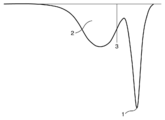
- a conceptual diagram is shown in FIG. In FIG. 1, 1 represents the peak top melting point on the highest temperature side in the DSC second melting curve, 2 represents the integration of melting enthalpies at a temperature of 110 ° C. or less in the DSC second melting curve, and 3 represents The boundary line of the temperature of 110 degreeC in the second melting curve of DSC is shown. Resin composition having excellent moldability when the ratio of the melting enthalpy at a temperature of 110 ° C.
- Xc to the total melting enthalpy in the DSC melting curve of component (A3) is 50% or more. You can get things. Moreover, the film formed from such a resin composition has favorable electrolytic solution resistance. Xc of a component (A3) becomes like this. Preferably it is 60% or more. On the other hand, from the viewpoint of the bending resistance and heat resistance of the film to be formed, Xc of the component (A3) is 80% or less, preferably 70% or less.
- the component (A3) is not particularly limited as long as it is a polyethylene that satisfies the characteristics (p) and (q).
- low density polyethylene linear low density polyethylene, ultra low density polyethylene, high density polyethylene, ethylene homopolymer, ethylene and ⁇ -olefin (for example, 1-butene, 1-hexene, 1-octene, etc. Or a copolymer with two or more).
- these 1 type can be used individually or as a mixture which mix
- the carbon nanotube of component (B) has a diameter of about 1 to 250 nm and a length of 0.1 to about 6-membered ring network (graphene sheet) made of carbon in a single-layer or multi-layer coaxial tubular shape. It is a fibrous substance of about 250 ⁇ m.
- the carbon nanotube of the component (B) functions to impart high conductivity to the resin composition and the film as a conductive filler. Therefore, the carbon nanotube of component (B) is preferably one having few lattice defects and high conductivity. Moreover, since the thing with small bulk specific gravity is easy to open, it is preferable.
- Nanosil S.I. A “Nanosil NC7000” (trade name) of the company, “VGCF-X” (trade name) of Showa Denko K.K.
- Component (B) is blended in an amount of 1 part by mass or more, preferably 10 parts by mass or more, more preferably 20 parts by mass or more from the viewpoint of conductivity with respect to 100 parts by mass of component (A). Moreover, from a viewpoint of tensile elongation and bending resistance, it is 60 mass parts or less, Preferably it is 50 mass parts or less, More preferably, it is 45 mass parts or less.
- the acetylene black of the component (C) is a carbon fine particle produced by thermal decomposition of acetylene gas, and is a conductive carbon black having a partially graphitized structure.
- the component (C) acetylene black maintains the processability in the resin composition production (melt-kneading) step and the film-forming step, and helps the component (B) to be defibrated and highly dispersed. And mechanical properties such as tensile elongation and bending resistance can be improved.
- acetylene black of a component (C) itself has electroconductivity, it functions to raise the electroconductivity of a resin composition and its film.
- Examples of commercially available acetylene black include Denka Black (trade name) manufactured by Denki Kagaku Kogyo Co., Ltd.
- Component (C) is blended in an amount of 1 part by mass or more, preferably 6 parts by mass or more, more preferably 100 parts by mass of component (A) from the viewpoint of tensile elongation and bending resistance of the resulting film. It is 10 parts by mass or more.
- the blending amount of component (C) is 60 parts by mass or less, preferably 40 parts by mass or less, more preferably 30 parts by mass, from the viewpoint of the electrolytic solution resistance, tensile elongation, and bending resistance of the resulting film. It is as follows.
- Ketjen black is known as conductive carbon black in addition to acetylene black. Ketjen black has high conductivity, but unlike acetylene black, it has a hollow shell-like structure. Therefore, the conductive filler mainly containing this is kneaded with the component (A) and the component (B). The resin composition thus obtained does not exhibit melt ductility during film formation and is difficult to form.
- additives such as lubricants, antioxidants, anti-aging agents, weathering stabilizers such as light stabilizers and ultraviolet absorbers, heat stabilizers, copper damage inhibitors, mold release agents
- An additive such as an agent and a surfactant can be further contained as long as the object of the present invention is not adversely affected.
- the compounding amount of such an additive may be about 0.001 to 5 parts by mass with respect to 100 parts by mass of the component (A).
- inorganic fillers other than the components (B) and (C) can be further contained as long as they do not contradict the purpose of the present invention.
- examples of such inorganic fillers include light calcium carbonate, heavy calcium carbonate, hydrous magnesium silicate, and talc.
- the compounding amount of the inorganic filler may be about 1 to 20 parts by mass with respect to 100 parts by mass of the component (A).
- the resin composition of the present invention can be obtained by melt kneading the above components (A) to (C) and other optional components used as desired using an arbitrary melt kneader.
- the melt kneader include batch kneaders such as a pressure kneader and a mixer; extrusion kneaders such as a co-rotating twin screw extruder and a different direction rotating twin screw extruder; and a calender roll kneader. These may be used in any combination.
- the obtained resin composition can be formed into a film using, for example, a calendering machine or an extruder and a T-die after being pelletized by an arbitrary method. Pelletization can be performed by methods such as hot cutting, strand cutting, and underwater cutting. Alternatively, the melt-kneaded resin composition may be directly sent to a calendering machine or a T-die to form a film. Any calendar processing machine can be used, and examples thereof include an upright three roll, an upright four roll, an L four roll, an inverted L four roll, and a Z roll. .
- Any extruder can be used, and examples thereof include a single-screw extruder, a same-direction rotating twin-screw extruder, and a different-direction rotating twin-screw extruder.
- Any T die can be used, and examples thereof include a manifold die, a fishtail die, and a coat hanger die.
- the thickness of the film thus obtained is not particularly limited, but may be, for example, 100 to 1000 ⁇ m when used as an electrode member of a redox flow battery (storage battery) using a sulfuric acid aqueous solution of vanadium as both electrodes.
- the film may be crosslinked and cured by a known method, for example, electron beam irradiation, in order to increase its heat resistance and electrolytic solution resistance.
- volume resistivity ⁇ Based on JIS K7194: 1994, the volume resistivity of the film was measured by a four-probe method (probe method). A film that had been conditioned for 24 hours or more in a test room at a temperature of 23 ⁇ 2 ° C. and a relative humidity of 50 ⁇ 5% was cut into a size of 80 mm in the machine direction of the film and 50 mm in the width direction of the film to obtain a test piece. .
- Raw materials used Ingredient (A1) (A1-1): Showa Denko Co., Ltd.'s chlorinated polyethylene “Elaslene 303A” (trade name), chlorine content 32 mass%, melt flow rate (180 ° C., 211.8 N) 120 g / 10 min, heat of fusion 2 J / g (A1-2): Chlorinated polyethylene “Elaslene 303B” (trade name), Showa Denko Co., Ltd., chlorine content 32 mass%, melt flow rate (180 ° C., 211.8 N) 25 g / 10 minutes, heat of fusion 50 J / g (A1-3): Chlorinated polyethylene “Elaslene 404B” (trade name), Showa Denko Co., Ltd., chlorine content 40 mass%, melt flow rate (180 ° C., 211.8 N) 25 g / 10 min, heat of fusion 29 J / g
- Ingredient (A2) (A2-1): The Dow Chemical Company polyethylene “engage 8402” (trade name), melt flow rate (190 ° C., 21.18 N) 30 g / 10 min, density 877 Kg / m 3 , Tm-A2: 99 ° C (A2-2): Prime Polymer Co., Ltd. polyethylene “Ultzex 20200J” (trade name), melt flow rate (190 ° C., 21.18 N) 18.5 g / 10 min, density 918 Kg / m 3 , Tm-A2: 125 ° C
- Ingredient (A3) (A3-1): Prime Polymer Co., Ltd. polyethylene “Ultzex 20200J” (trade name), melt flow rate (190 ° C., 21.18 N) 18.5 g / 10 min, density 918 Kg / m 3 , Tm-A3: 125 ° C, Xc 62% (A3-2): Prime Polymer Co., Ltd. polyethylene “Neozex 2024G” (trade name), melt flow rate (190 ° C., 21.18 N) 25 g / 10 min, density 915 Kg / m 3 , Tm-A3: 120 ° C. Xc 75% (A3-3): Prime Polymer Co., Ltd.
- Comparative component (A3 ′) (A3′-1): The Dow Chemical Company polyethylene “D9100.00” (trade name), melt flow rate (190 ° C., 21.18 N) 1 g / 10 min, density 877 Kg / m 3 , Tm— A3: 118 ° C., Xc 29% (A3′-2): The Dow Chemical Company polyethylene “engage 8402” (trade name), melt flow rate (190 ° C., 21.18 N) 30 g / 10 min, density 877 Kg / m 3 , Tm-A3 : 99 ° C, Xc 100% (A3′-3): Prime Polymer Co., Ltd.
- Ingredient (B) (B-1): Nanosil S.I. A. Multi-walled carbon nanotube “Nanosil NC7000” (trade name), average diameter 9.5 nm, average length 1.5 ⁇ m, bulk specific gravity 0.043 g / cm 3 , purity 90% by mass
- Ingredient (C) (C-1): Acetylene black “Denka Black Granule” (trade name) manufactured by Denki Kagaku Kogyo Co., Ltd., average particle diameter of primary particles 35 nm (measured by observation with an electron microscope (TEM)), specific surface area 69 m 2 / g
- Comparative component (C ') (C'-1): Lion Corporation Ketjen Black “KJ300” (trade name)
- Component (D) Optional component (D-1): Stabilizer for chlorinated polyethylene “STANN JF-95B” (trade name) manufactured by Nitto Kasei Kogyo Co., Ltd.
- the film formed from the resin composition of the present invention is resistant to electrolytic solution, volume resistivity, bending resistance, bending resistance after wet heat treatment,
- various properties of tensile elongation were expressed at a high level in a well-balanced manner.
- initial conductivity was also excellent.
- melt flow rates were lower than (A1-1) and crystalline (A1-2) or (A1-3) were used)
- a sufficiently good initial Since conductivity was not obtained, but low volume resistivity was obtained, it can be evaluated that a film sufficient for practical use was obtained from the viewpoint of conductivity in addition to other characteristics.
- Comparative Example 1 had a large amount of component (A2), and the bending resistance after wet heat treatment was insufficient. In Comparative Example 2, the amount of the component (A2) was small and the electrolytic solution resistance was poor. Comparative Examples 3 to 5 are examples in which component (C) is not used. When the component (B) is small, the initial conductivity does not reach that of Examples 1 and 7. When the component (B) is large, is the bending resistance or the bending resistance after wet heat treatment insufficient? It was inferior. Since Comparative Example 6 did not use the component (B), the initial conductivity was inferior and the volume resistivity was large. Moreover, the bending resistance and the bending resistance after wet heat treatment were also inferior.
- Comparative Example 7 is an example using Ketjen black instead of the component (C), it could not be formed into a film. Therefore, tests (i) to (vi) were omitted. Since Comparative Example 8 had a low Tm-A3 and a low Xc, it was inferior in electrolytic solution resistance, and had insufficient bending resistance and bending resistance after wet heat treatment. Since Comparative Example 9 had a low Tm-A3 and a high Xc, the bending resistance and the bending resistance after wet heat treatment were inferior.
- the film formed from the resin composition according to the present invention is an electrode member of a storage battery, particularly an electrode in an electrolyte circulation type secondary battery, such as a redox flow battery, a zinc / chlorine battery, and a zinc / bromine battery, or a coating protection thereof. Can be suitably used.
Abstract
The purpose of the present invention is to provide an electrically conductive resin composition which enables the formation of a film that has high electrical conductivity and excellent tensile elongation, bending resistance and flexibility, and is suitable for an electrode member for a storage battery. A first embodiment is a resin composition comprising (A) 100 parts by mass of a thermoplastic resin, (B) 1 to 60 parts by mass of carbon nanotubes and (C) 1 to 60 parts by mass of acethylene black, wherein the thermoplastic resin (A) comprises (A1) 30 to 80% by mass of a chlorinated polyethylene having a chlorine content of 20 to 45% by mass and (A2) 70 to 20% by mass of a polyethylene that is different from the component (A1). In a second embodiment, the thermoplastic resin (A) is (A3) a polyethylene that satisfies the following properties (p) and (q): (p) the peak top melting point on the highest temperature side in a DSC melting curve is 120˚C or higher; and (q) the ratio of melting enthalpy in a temperature range of 110˚C or lower relative to the total melting enthalpy in the DSC melting curve is 50 to 80%.
Description
本発明は、導電性樹脂組成物及びそのフィルムに関する。更に詳しくは、本発明は、蓄電池の電極又はその被覆保護に好適なフィルムを形成可能な導電性樹脂組成物、及びそのフィルムに関する。
The present invention relates to a conductive resin composition and a film thereof. More specifically, the present invention relates to a conductive resin composition capable of forming an electrode of a storage battery or a film suitable for covering protection thereof, and a film thereof.
近年、石油等の化石燃料や原子力に替わる新たなエネルギー源として太陽光発電、風力発電及び波力発電などの所謂再生可能エネルギーが注目を集めている。しかし、これらの再生可能エネルギーは、天候等の影響を強く受けるため、出力が極めて不安定である。従って、これらのエネルギーを大量に電力網につなげるためには、例えば、大容量の蓄電池を併設して出力変動の平準化等を行うことが必要である。
In recent years, so-called renewable energies such as solar power generation, wind power generation and wave power generation have attracted attention as new energy sources to replace fossil fuels such as oil and nuclear power. However, since these renewable energies are strongly affected by the weather, the output is extremely unstable. Therefore, in order to connect a large amount of these energies to the power grid, for example, it is necessary to level out output fluctuations with a large capacity storage battery.
大容量の蓄電池の一つにレドックスフロー電池がある。レドックスフロー電池は2種類のイオン溶液を陽イオン交換膜で隔て、両方の溶液に設けた電極上で酸化反応と還元反応を同時に進めることにより充放電を行うものである。例えば、バナジウムの硫酸水溶液を両極に用いるレドックスフロー電池では、充電時に、プラス極において4価のバナジウムが5価に酸化され、マイナス極において3価のバナジウムが2価に還元される。放電時には、この逆の反応が起こる。レドックスフロー電池は、設備の大型化が容易であるという特長を有する。また、レドックスフロー電池は、室温で作動し、かつ燃焼性や爆発性を有する物質を使用せず、またそのような物質の発生もないため、ナトリウム・硫黄電池やリチウムイオン二次電池と比較して安全性に優れている。
There is a redox flow battery as one of large-capacity storage batteries. A redox flow battery performs charge / discharge by separating two types of ion solutions with a cation exchange membrane and simultaneously carrying out an oxidation reaction and a reduction reaction on electrodes provided in both solutions. For example, in a redox flow battery using a sulfuric acid aqueous solution of vanadium for both electrodes, tetravalent vanadium is oxidized to pentavalent at the positive electrode and trivalent vanadium is reduced to divalent at the negative electrode during charging. The reverse reaction occurs during discharge. The redox flow battery has a feature that the equipment can be easily enlarged. Redox flow batteries operate at room temperature, do not use flammable or explosive substances, and do not generate such substances. Compared with sodium-sulfur batteries and lithium ion secondary batteries. And excellent safety.
レドックスフロー電池の電極は、硫酸水溶液等の電解液中に浸漬され、かつ、そこで酸化還元反応が起こる。従って、その電極は、高い導電性および耐薬品性が必要であり、炭素繊維集合体や白金めっきが電極として使用されている。しかし、炭素繊維集合体は通液性を有するため、炭素繊維集合体と銅線との接続部が、輸送された硫酸水溶液等に侵されるという不都合があった。また白金めっきは非常に良い導体であり、かつ耐薬品性にも優れているが、貴金属であり高価という難点がある。
The electrode of the redox flow battery is immersed in an electrolyte such as an aqueous sulfuric acid solution, and an oxidation-reduction reaction takes place there. Accordingly, the electrode needs to have high conductivity and chemical resistance, and a carbon fiber aggregate or platinum plating is used as the electrode. However, since the carbon fiber aggregate has liquid permeability, there is a disadvantage that the connecting portion between the carbon fiber aggregate and the copper wire is affected by the transported sulfuric acid aqueous solution or the like. Platinum plating is a very good conductor and excellent in chemical resistance, but it is a noble metal and has a drawback of being expensive.
そこで、ケッチェンブラック等の導電性カーボンを練り込んだ導電性樹脂フィルムを電極として用いること(例えば、特許文献1~4参照)や、炭素繊維集合体又は銅板等の電極を前記導電性樹脂フィルムにより被覆することが行われている。しかし、これらの導電性樹脂フィルムは、十分に高い導電性を付与すべく多量の導電性カーボンを練り込むと、引張伸び、耐折曲性、及び柔軟性が全く不十分であり、物理的な力で容易に壊れるという不都合がある。また、導電性カーボンの配合量を少なくして引張伸び、耐折曲性、及び柔軟性を確保すると、体積抵抗率が10Ω・cmを超えるものになる。このような導電性フィルムを電極又はその被覆に使用したレドックスフロー電池は、内部抵抗が大きくなるという点で満足できるものではない。
Therefore, a conductive resin film kneaded with conductive carbon such as ketjen black is used as an electrode (see, for example, Patent Documents 1 to 4), and an electrode such as a carbon fiber aggregate or a copper plate is used as the conductive resin film. It is performed by coating. However, when these conductive resin films are kneaded with a large amount of conductive carbon to give sufficiently high conductivity, the tensile elongation, the bending resistance, and the flexibility are quite insufficient. There is an inconvenience that it is easily broken by force. Moreover, if tensile elongation, bending resistance, and flexibility are ensured by reducing the blending amount of the conductive carbon, the volume resistivity exceeds 10 Ω · cm. A redox flow battery using such a conductive film as an electrode or its coating is not satisfactory in that the internal resistance is increased.
また近年、カーボンナノチューブが導電性カーボンとして注目されており、上記の不都合を解決できるのではないかと期待されている(例えば、特許文献5及び非特許文献1参照)。しかし、カーボンナノチューブは解繊し難く、従って樹脂への分散が非常に難しいという不都合がある。そのため十分に高い導電性を得るためには、ケッチェンブラックと同様に、多量のカーボンナノチューブを配合しなければならない。このような多量のカーボンナノチューブの配合により、結局、導電性樹脂フィルムの引張伸び、耐折曲性、及び柔軟性は実用的に不十分である。また、カーボンナノチューブの解繊・分散状態を良くすべく、解繊・分散工程におけるせん断応力を高くすると、カーボンナノチューブが壊れてしまう。従って、解繊・分散工程におけるせん断応力を高くしたとしても、十分に高い導電性を得るためには、カーボンナノチューブを多量に配合することがやはり必要になる。
In recent years, carbon nanotubes have attracted attention as conductive carbon, and it is expected that the above disadvantages can be solved (see, for example, Patent Document 5 and Non-Patent Document 1). However, carbon nanotubes are difficult to defibrate and are therefore very difficult to disperse in resin. Therefore, in order to obtain sufficiently high conductivity, a large amount of carbon nanotubes must be blended in the same manner as ketjen black. As a result of such a large amount of carbon nanotube blending, the tensile elongation, bending resistance, and flexibility of the conductive resin film are practically insufficient. Further, if the shear stress in the defibrating / dispersing step is increased in order to improve the defibrated / dispersed state of the carbon nanotube, the carbon nanotube is broken. Therefore, even if the shear stress is increased in the defibration / dispersion step, it is necessary to add a large amount of carbon nanotubes in order to obtain sufficiently high conductivity.
またカーボンブラック又はカーボンナノチューブをプロピレン-オレフィンコポリマーワックスと混合してマスターバッチとし、これを有機ポリマーと混合して得られる組成物からなる導電性フィルムが提案されている(例えば、特許文献6及び7参照)。上記マスターバッチは、カーボンブラック又はカーボンナノチューブの高充填を可能にするが、得られるフィルムの導電性は十分ではない。
In addition, conductive films made of a composition obtained by mixing carbon black or carbon nanotubes with a propylene-olefin copolymer wax to form a master batch and mixing with an organic polymer have been proposed (for example, Patent Documents 6 and 7). reference). The masterbatch enables high filling of carbon black or carbon nanotubes, but the resulting film is not sufficiently conductive.
本発明の目的は、高い導電性を有し、かつ、引張伸び、耐折曲性、及び柔軟性に優れ、蓄電池の電極部材、特に電解液循環型二次電池、例えば、レドックスフロー電池、亜鉛・塩素電池、及び亜鉛・臭素電池等における電極又はその被覆保護に好適なフィルムを形成可能な導電性樹脂組成物を提供することである。
本発明の更なる目的は、このような導電性樹脂組成物から形成されたフィルムを提供することである。 It is an object of the present invention to have high conductivity, excellent tensile elongation, bending resistance, and flexibility, and an electrode member of a storage battery, particularly an electrolyte circulation type secondary battery such as a redox flow battery, zinc -It is providing the conductive resin composition which can form the film suitable for the electrode in a chlorine battery, a zinc-bromine battery, etc. or its coating | cover protection.
A further object of the present invention is to provide a film formed from such a conductive resin composition.
本発明者は、鋭意研究した結果、特定の熱可塑性樹脂と特定の導電性カーボンとを適当な量で用いることにより、上記課題を達成できることを見出した。
As a result of intensive studies, the present inventor has found that the above-described problems can be achieved by using a specific thermoplastic resin and a specific conductive carbon in appropriate amounts.
すなわち、本発明の第一の形態は、以下のとおりである。
(A)熱可塑性樹脂100質量部;
(B)カーボンナノチューブ1~60質量部;及び
(C)アセチレンブラック1~60質量部
を含み、
上記(A)熱可塑性樹脂は、
(A1)塩素含有量20~45質量%の塩素化ポリエチレン30~80質量%と、
(A2)上記(A1)とは異なるポリエチレン70~20質量%とからなり、
ここで(A1)と(A2)との和は100質量%であること
を特徴とする樹脂組成物。 That is, the first form of the present invention is as follows.
(A) 100 parts by mass of a thermoplastic resin;
(B) 1 to 60 parts by mass of carbon nanotubes; and (C) 1 to 60 parts by mass of acetylene black,
The (A) thermoplastic resin is
(A1) 30-80% by mass of chlorinated polyethylene having a chlorine content of 20-45% by mass;
(A2) comprising 70 to 20% by mass of polyethylene different from the above (A1),
Here, the sum of (A1) and (A2) is 100 mass%, The resin composition characterized by the above-mentioned.
本発明の第二の形態は、以下のとおりである。
(A)熱可塑性樹脂100質量部;
(B)カーボンナノチューブ1~60質量部;及び
(C)アセチレンブラック1~60質量部
を含み、
上記(A)熱可塑性樹脂は、
(A3)下記特性(p)及び(q)を満たすポリエチレンであること
を特徴とする樹脂組成物:
(p)DSC融解曲線における最も高い温度側のピークトップ融点が、120℃以上であること;及び
(q)DSC融解曲線における全融解エンタルピーに対する温度110℃以下の融解エンタルピーの割合が50~80%であること。 The second aspect of the present invention is as follows.
(A) 100 parts by mass of a thermoplastic resin;
(B) 1 to 60 parts by mass of carbon nanotubes; and (C) 1 to 60 parts by mass of acetylene black,
The (A) thermoplastic resin is
(A3) A resin composition characterized by being a polyethylene satisfying the following characteristics (p) and (q):
(P) The peak top melting point on the highest temperature side in the DSC melting curve is 120 ° C. or higher; and (q) The ratio of the melting enthalpy at a temperature of 110 ° C. or lower to the total melting enthalpy in the DSC melting curve is 50 to 80%. Be.
本発明の樹脂組成物は、フィルム成形加工性に優れており、これを成形してなるフィルムは、高い導電性を有し、かつ、引張伸び、耐折曲性、及び柔軟性に優れる。そのため、当該樹脂組成物から形成されたフィルムは、蓄電池の電極部材、特に電解液循環型二次電池、例えば、レドックスフロー電池、亜鉛・塩素電池、及び亜鉛・臭素電池等における電極又はその被覆保護に好適に用いることができる。
The resin composition of the present invention is excellent in film molding processability, and a film formed by molding the resin composition has high conductivity, and is excellent in tensile elongation, bending resistance, and flexibility. Therefore, the film formed from the resin composition is an electrode member of a storage battery, in particular, an electrolyte circulating secondary battery, for example, an electrode in a redox flow battery, a zinc / chlorine battery, a zinc / bromine battery, etc. Can be suitably used.
本発明の樹脂組成物を構成する各成分について説明する。
Each component constituting the resin composition of the present invention will be described.
(A)熱可塑性樹脂
成分(A)の熱可塑性樹脂は、炭素フィラーである成分(B)を受容するとともに、フィルム成形加工性を担保し、得られるフィルムに、引張伸び、耐折曲性、及び柔軟性などの機械的物性を付与する働きをする。 (A) The thermoplastic resin of the thermoplastic resin component (A) accepts the component (B) which is a carbon filler, ensures film forming processability, and the resulting film has tensile elongation, bending resistance, It also functions to impart mechanical properties such as flexibility.
成分(A)の熱可塑性樹脂は、炭素フィラーである成分(B)を受容するとともに、フィルム成形加工性を担保し、得られるフィルムに、引張伸び、耐折曲性、及び柔軟性などの機械的物性を付与する働きをする。 (A) The thermoplastic resin of the thermoplastic resin component (A) accepts the component (B) which is a carbon filler, ensures film forming processability, and the resulting film has tensile elongation, bending resistance, It also functions to impart mechanical properties such as flexibility.
本発明の第一の形態において、成分(A)の熱可塑性樹脂は、(A1)塩素含有量20~45質量%の塩素化ポリエチレン30~80質量%と、(A2)上記(A1)とは異なるポリエチレン70~20質量%とからなる熱可塑性樹脂混合物である。ここで(A1)と(A2)との和は100質量%である。上記の熱可塑性樹脂混合物を成分(A)として用いることにより、耐電解液性、特に耐硫酸バナジウム水溶液性の極めて良好な樹脂組成物のフィルムを得ることができる。配合比率は、好ましくは、成分(A1)50~65質量%と(A2)50~35質量%である。
In the first embodiment of the present invention, the thermoplastic resin of component (A) comprises (A1) 30 to 80% by mass of chlorinated polyethylene having a chlorine content of 20 to 45% by mass, and (A2) the above (A1). It is a thermoplastic resin mixture comprising 70 to 20% by mass of different polyethylene. Here, the sum of (A1) and (A2) is 100% by mass. By using the above-mentioned thermoplastic resin mixture as the component (A), a film of a resin composition having a very good electrolytic solution resistance, in particular, a vanadium sulfate-resistant aqueous solution property can be obtained. The blending ratio is preferably 50 to 65% by mass of component (A1) and 50 to 35% by mass of (A2).
(A1)塩素化ポリエチレン
成分(A1)の塩素含有量20~45質量%の塩素化ポリエチレンは、得られるフィルムの耐硫酸バナジウム水溶液性の確保に重要な役割を担う。一方、塩素を含むため、成形加工時に焼けなどのトラブルの原因にならないように留意するべきである。そのため、塩素含有量は20~45質量%であることが必要である。塩素含有量が45質量%以下であることによって、成形加工時に焼けなどのトラブルの発生可能性を抑制することができる。塩素含有量が20質量%以上であることによって、耐硫酸バナジウム水溶液性の確保という塩素化ポリエチレンの配合目的を満たすことができる。塩素含有量は、好ましくは25~40質量%である。 (A1) Chlorinated polyethylene having a chlorine content of 20 to 45 mass% in the chlorinated polyethylene component (A1) plays an important role in ensuring the vanadium sulfate aqueous solution resistance of the resulting film. On the other hand, since it contains chlorine, care should be taken not to cause troubles such as burning during molding. Therefore, the chlorine content needs to be 20 to 45% by mass. When the chlorine content is 45% by mass or less, it is possible to suppress the possibility of troubles such as burning during molding. When the chlorine content is 20% by mass or more, the chlorinated polyethylene blending purpose of ensuring the vanadium sulfate-resistant aqueous solution property can be satisfied. The chlorine content is preferably 25 to 40% by mass.
成分(A1)の塩素含有量20~45質量%の塩素化ポリエチレンは、得られるフィルムの耐硫酸バナジウム水溶液性の確保に重要な役割を担う。一方、塩素を含むため、成形加工時に焼けなどのトラブルの原因にならないように留意するべきである。そのため、塩素含有量は20~45質量%であることが必要である。塩素含有量が45質量%以下であることによって、成形加工時に焼けなどのトラブルの発生可能性を抑制することができる。塩素含有量が20質量%以上であることによって、耐硫酸バナジウム水溶液性の確保という塩素化ポリエチレンの配合目的を満たすことができる。塩素含有量は、好ましくは25~40質量%である。 (A1) Chlorinated polyethylene having a chlorine content of 20 to 45 mass% in the chlorinated polyethylene component (A1) plays an important role in ensuring the vanadium sulfate aqueous solution resistance of the resulting film. On the other hand, since it contains chlorine, care should be taken not to cause troubles such as burning during molding. Therefore, the chlorine content needs to be 20 to 45% by mass. When the chlorine content is 45% by mass or less, it is possible to suppress the possibility of troubles such as burning during molding. When the chlorine content is 20% by mass or more, the chlorinated polyethylene blending purpose of ensuring the vanadium sulfate-resistant aqueous solution property can be satisfied. The chlorine content is preferably 25 to 40% by mass.
塩素化の対象であるポリエチレンは、特に限定されないが、例えば、低密度ポリエチレン、直鎖状低密度ポリエチレン、超低密度ポリエチレン、高密度ポリエチレン、エチレン単独重合体、エチレンとα-オレフィン(例えば、1-ブテン、1-ヘキセン、1-オクテン等の1つ又は2つ以上)とのコポリマー、及びそれらの任意の混合物を挙げることができる。塩素化は、上記範囲内の塩素含有量を得ることが可能である限り、公知のいかなる方法によって行われてもよい。典型的には、水性懸濁法を用いることができる。
The polyethylene to be chlorinated is not particularly limited. For example, low density polyethylene, linear low density polyethylene, ultra low density polyethylene, high density polyethylene, ethylene homopolymer, ethylene and α-olefin (for example, 1 -Butene, 1-hexene, 1-octene and the like) and any mixtures thereof. Chlorination may be carried out by any known method as long as it is possible to obtain a chlorine content within the above range. Typically, an aqueous suspension method can be used.
成分(A1)は、成形加工時のせん断応力を低減して焼けなどのトラブルを防止すると共に、成分(B)及び成分(C)を良好に分散させて初期導電性を良好にする観点から、非結晶性であることが好ましい。
Component (A1) reduces the shear stress at the time of molding and prevents troubles such as burning, and from the viewpoint of favorably dispersing component (B) and component (C) to improve initial conductivity, It is preferably non-crystalline.
なお、本明細書において、非結晶性塩素化ポリエチレンとは、株式会社パーキンエルマージャパンのDiamond DSC型示差走査熱量計を使用して、190℃で5分間保持し、10℃/分で-10℃まで冷却し、-10℃で5分間保持し、10℃/分で190℃まで昇温するプログラムで測定されるセカンド融解曲線(最後の昇温過程で測定される融解曲線)において、明確な融解ピークが認められないもの、又は、融解ピークは存在するが、その融解熱量(ΔH)が10J/g未満であるものと定義する。
In the present specification, the non-crystalline chlorinated polyethylene means that a Diamond DSC type differential scanning calorimeter manufactured by PerkinElmer Japan Co., Ltd. is used and held at 190 ° C. for 5 minutes, and at −10 ° C. at 10 ° C./min. Clear melting in the second melting curve (melting curve measured in the last heating process) measured with a program that cools to -10 ° C and holds for 5 minutes and heats up to 190 ° C at 10 ° C / min It is defined that no peak is observed or that a melting peak is present but the heat of fusion (ΔH) is less than 10 J / g.
また、成分(A1)は、成形加工時のせん断応力を低減して焼けなどのトラブルを防止すると共に、成分(B)及び成分(C)を良好に分散させて初期導電性を良好にする観点から、流動性の高いものが好ましい。成分(A1)について、JIS K7210:1999に準拠し、180℃、211.8Nの条件で測定したメルトフローレート(以下、MFR-A1と略すことがある。)は10g/10分以上であるものが好ましく、50g/10分以上であるものがより好ましい。一方、成分(B)の十分な受容性を担保するための流動性とする観点から、成分(A1)のMFR-A1は、500g/10分以下であることが好ましい。
In addition, the component (A1) reduces the shear stress at the time of molding to prevent troubles such as burning, and the component (B) and the component (C) are well dispersed to improve the initial conductivity. Therefore, those having high fluidity are preferable. The component (A1) has a melt flow rate (hereinafter sometimes abbreviated as MFR-A1) measured at 180 ° C. and 211.8 N in accordance with JIS K7210: 1999 of 10 g / 10 min or more. Is preferable, and more preferably 50 g / 10 min or more. On the other hand, from the viewpoint of fluidity to ensure sufficient acceptability of the component (B), the MFR-A1 of the component (A1) is preferably 500 g / 10 min or less.
このような塩素化ポリエチレンの市販例としては、昭和電工株式会社の「エラスレン303A」(商品名)、「エラスレン302NA」(商品名)などを挙げることができる。
Examples of such commercially available chlorinated polyethylenes include “Eraslen 303A” (trade name) and “Eraslen 302NA” (trade name) from Showa Denko KK.
(A2)上記(A1)と異なるポリエチレン
成分(A2)のポリエチレンは、(A1)と異なるポリエチレンである限り、特に限定されない。成分(A2)のポリエチレンは、通常、塩素化されていない。成分(A2)のポリエチレンとしては、例えば、低密度ポリエチレン、直鎖状低密度ポリエチレン、超低密度ポリエチレン、高密度ポリエチレン、エチレン単独重合体、エチレンとα-オレフィン(例えば、1-ブテン、1-ヘキセン、1-オクテン等の1つ又は2つ以上)とのコポリマーなどの1種を単独で、又は2種以上を任意に配合した混合物として用いることができる。混合物として用いる場合には、混合物全体が下記Tm-A2の範囲や下記MFR-A2の範囲を満たすようにすることが好ましい。 (A2) The polyethylene of the polyethylene component (A2) different from (A1) is not particularly limited as long as it is a polyethylene different from (A1). The polyethylene of component (A2) is usually not chlorinated. Examples of the component (A2) polyethylene include low density polyethylene, linear low density polyethylene, ultra-low density polyethylene, high density polyethylene, ethylene homopolymer, ethylene and α-olefin (eg, 1-butene, 1- One kind of a copolymer with one or two or more of hexene, 1-octene, etc.) can be used alone or as a mixture in which two or more kinds are arbitrarily blended. When used as a mixture, the entire mixture preferably satisfies the following Tm-A2 range or the following MFR-A2 range.
成分(A2)のポリエチレンは、(A1)と異なるポリエチレンである限り、特に限定されない。成分(A2)のポリエチレンは、通常、塩素化されていない。成分(A2)のポリエチレンとしては、例えば、低密度ポリエチレン、直鎖状低密度ポリエチレン、超低密度ポリエチレン、高密度ポリエチレン、エチレン単独重合体、エチレンとα-オレフィン(例えば、1-ブテン、1-ヘキセン、1-オクテン等の1つ又は2つ以上)とのコポリマーなどの1種を単独で、又は2種以上を任意に配合した混合物として用いることができる。混合物として用いる場合には、混合物全体が下記Tm-A2の範囲や下記MFR-A2の範囲を満たすようにすることが好ましい。 (A2) The polyethylene of the polyethylene component (A2) different from (A1) is not particularly limited as long as it is a polyethylene different from (A1). The polyethylene of component (A2) is usually not chlorinated. Examples of the component (A2) polyethylene include low density polyethylene, linear low density polyethylene, ultra-low density polyethylene, high density polyethylene, ethylene homopolymer, ethylene and α-olefin (eg, 1-butene, 1- One kind of a copolymer with one or two or more of hexene, 1-octene, etc.) can be used alone or as a mixture in which two or more kinds are arbitrarily blended. When used as a mixture, the entire mixture preferably satisfies the following Tm-A2 range or the following MFR-A2 range.
成分(A2)は、フィルム成形加工性の確保に重要な働きをする。そのためフィラー包含性に優れたものが好ましく、成分(A2)のDSC融解曲線における最も高い温度側のピークトップ融点(以下、Tm-A2と略すことがある。)は、110℃以下のものが好ましい。このTm-A2は、より好ましくは105℃以下である。一方、電解液による成分(A2)の膨潤を抑制する観点から、Tm-A2は、好ましくは60℃以上である。
Component (A2) plays an important role in ensuring film formability. Therefore, those having excellent filler inclusion properties are preferred, and the peak top melting point (hereinafter sometimes abbreviated as Tm-A2) on the DSC melting curve of component (A2) is preferably 110 ° C. or less. . This Tm-A2 is more preferably 105 ° C. or lower. On the other hand, from the viewpoint of suppressing swelling of the component (A2) by the electrolytic solution, Tm-A2 is preferably 60 ° C. or higher.
なお、本明細書において、DSC融解曲線における最も高い温度側のピークトップ融点とは、株式会社パーキンエルマージャパンのDiamond DSC型示差走査熱量計を使用して、190℃で5分間保持し、10℃/分で-10℃まで冷却し、-10℃で5分間保持し、10℃/分で190℃まで昇温するプログラムで測定されるセカンド融解曲線(最後の昇温過程で測定される融解曲線)において、最も高い温度側のピークトップ融点をいう。
In this specification, the peak top melting point on the highest temperature side in the DSC melting curve is a Diamond DSC type differential scanning calorimeter manufactured by PerkinElmer Japan Co., Ltd., held at 190 ° C. for 5 minutes, and 10 ° C. Second melting curve measured by a program that cools to -10 ° C at / min, holds at -10 ° C for 5 min, and raises the temperature to 190 ° C at 10 ° C / min (melting curve measured in the last temperature raising process) ), The peak top melting point on the highest temperature side.
また、成分(A2)は、成形加工時のせん断応力を低減して焼けなどのトラブルを防止するため、流動性の高いものが好ましい。成分(A2)について、JIS K7210:1999に準拠し、190℃、21.18Nの条件で測定したメルトフローレート(以下、MFR-A2と略すことがある。)は1g/10分以上であるものが好ましく、5g/10分以上であるものがより好ましい。一方、成分(B)の十分な受容性を担保可能な流動性とする観点から、成分(A2)のMFR-A2は、100g/10分以下であることが好ましい。
In addition, the component (A2) preferably has high fluidity in order to reduce shear stress during molding and prevent troubles such as burning. The component (A2) has a melt flow rate (hereinafter sometimes abbreviated as MFR-A2) measured at 190 ° C. and 21.18 N in accordance with JIS K7210: 1999 of 1 g / 10 min or more. It is more preferable that it is 5 g / 10 min or more. On the other hand, the MFR-A2 of the component (A2) is preferably 100 g / 10 min or less from the viewpoint of fluidity that can ensure sufficient acceptability of the component (B).
(A3)特性(p)及び(q)を満たすポリエチレン
本発明の第二の形態において、成分(A)の熱可塑性樹脂は、(A3)下記特性(p)及び(q)を満たすポリエチレンである。
(p)DSC融解曲線における最も高い温度側のピークトップ融点が、120℃以上であること。
(q)DSC融解曲線における全融解エンタルピーに対する温度110℃以下の融解エンタルピーの割合が50~80%であること。 (A3) Polyethylene satisfying characteristics (p) and (q) In the second embodiment of the present invention, the thermoplastic resin of component (A) is (A3) polyethylene satisfying the following characteristics (p) and (q). .
(P) The peak top melting point on the highest temperature side in the DSC melting curve is 120 ° C. or higher.
(Q) The ratio of the melting enthalpy at a temperature of 110 ° C. or lower to the total melting enthalpy in the DSC melting curve is 50 to 80%.
成分(A3)を成分(A)として用いて得た樹脂組成物は、フィルム成形加工性が特に優れており、これを成形してなるフィルムは、耐折曲性や耐熱性が特に優れている。
The resin composition obtained by using the component (A3) as the component (A) is particularly excellent in film forming processability, and the film formed by molding the resin composition is particularly excellent in bending resistance and heat resistance. .
特性(p)
この特性(p)は、ポリエチレンの耐熱性の指標であり、上記の方法で測定される。成分(A3)のDSC融解曲線における最も高い温度側のピークトップ融点(以下、Tm-A3と略すことがある。)が、120℃以上であると、即ち特性(p)を満たすと、耐折曲性や耐熱性に優れたフィルムを得ることができる。Tm-A3は、高い方が好ましい。好ましくは125℃以上、より好ましくは130℃以上である。Tm-A3の上限は特にないが、ポリエチレンであるから、高くてもせいぜい135℃程度である。 Characteristics (p)
This characteristic (p) is an index of heat resistance of polyethylene and is measured by the above method. When the peak top melting point (hereinafter sometimes abbreviated as Tm-A3) in the DSC melting curve of the component (A3) is 120 ° C. or higher, that is, when the characteristic (p) is satisfied, A film excellent in curvature and heat resistance can be obtained. Tm-A3 is preferably as high as possible. Preferably it is 125 degreeC or more, More preferably, it is 130 degreeC or more. There is no particular upper limit for Tm-A3, but since it is polyethylene, it is at most about 135 ° C. at most.
特性(q)
この特性(q)は、ポリエチレンのフィラー包含性の指標であり、上記の方法で測定されるDSCのセカンド融解曲線における全融解エンタルピーに対する温度110℃以下の融解エンタルピーの割合である。概念図を図1に示す。図1において、1は、DSCのセカンド融解曲線での最も高い温度側のピークトップ融点を示し、2は、DSCのセカンド融解曲線での温度110℃以下の融解エンタルピーの積算を示し、3は、DSCのセカンド融解曲線での温度110℃の境界線を示す。成分(A3)のDSC融解曲線における全融解エンタルピーに対する温度110℃以下の融解エンタルピーの割合(以下、Xcと略すことがある。)が50%以上であると、優れた成形加工性を有する樹脂組成物を得ることができる。また、このような樹脂組成物から形成されるフィルムは、良好な耐電解液性を有する。成分(A3)のXcは、好ましくは60%以上である。一方、形成されるフィルムの耐折曲性や耐熱性の観点から、成分(A3)のXcは80%以下であり、好ましくは70%以下である。 Characteristics (q)
This characteristic (q) is an index of polyethylene filler inclusion, and is the ratio of the melting enthalpy at a temperature of 110 ° C. or less to the total melting enthalpy in the DSC second melting curve measured by the above method. A conceptual diagram is shown in FIG. In FIG. 1, 1 represents the peak top melting point on the highest temperature side in the DSC second melting curve, 2 represents the integration of melting enthalpies at a temperature of 110 ° C. or less in the DSC second melting curve, and 3 represents The boundary line of the temperature of 110 degreeC in the second melting curve of DSC is shown. Resin composition having excellent moldability when the ratio of the melting enthalpy at a temperature of 110 ° C. or less (hereinafter sometimes abbreviated as Xc) to the total melting enthalpy in the DSC melting curve of component (A3) is 50% or more. You can get things. Moreover, the film formed from such a resin composition has favorable electrolytic solution resistance. Xc of a component (A3) becomes like this. Preferably it is 60% or more. On the other hand, from the viewpoint of the bending resistance and heat resistance of the film to be formed, Xc of the component (A3) is 80% or less, preferably 70% or less.
上記成分(A3)は、上記特性(p)及び(q)を満たすポリエチレンである限り、特に限定されない。例えば、低密度ポリエチレン、直鎖状低密度ポリエチレン、超低密度ポリエチレン、高密度ポリエチレン、エチレン単独重合体、エチレンとα-オレフィン(例えば、1-ブテン、1-ヘキセン、1-オクテン等の1つ又は2つ以上)とのコポリマーなどを挙げることができる。成分(A3)としては、これらの1種を単独で、又は2種以上を任意に配合した混合物として用いることができる。混合物として用いる場合には、混合物全体が上記特性(p)及び(q)を満たすようにすればよい。
The component (A3) is not particularly limited as long as it is a polyethylene that satisfies the characteristics (p) and (q). For example, low density polyethylene, linear low density polyethylene, ultra low density polyethylene, high density polyethylene, ethylene homopolymer, ethylene and α-olefin (for example, 1-butene, 1-hexene, 1-octene, etc. Or a copolymer with two or more). As a component (A3), these 1 type can be used individually or as a mixture which mix | blended 2 or more types arbitrarily. When used as a mixture, the entire mixture may satisfy the above characteristics (p) and (q).
(B)カーボンナノチューブ
成分(B)のカーボンナノチューブは、炭素により作られる六員環のネットワーク(グラフェンシート)が単層あるいは多層の同軸管状になった直径1~250nm程度、長さ0.1~250μm程度の繊維状物質である。成分(B)のカーボンナノチューブは、導電性フィラーとして樹脂組成物及びそのフィルムに、高い導電性を付与する働きをする。そのため成分(B)のカーボンナノチューブは、格子欠陥が少なく、導電性の高いものが好ましい。また、嵩比重の小さいものが解繊し易いため好ましい。 (B) Carbon nanotube component The carbon nanotube of component (B) has a diameter of about 1 to 250 nm and a length of 0.1 to about 6-membered ring network (graphene sheet) made of carbon in a single-layer or multi-layer coaxial tubular shape. It is a fibrous substance of about 250 μm. The carbon nanotube of the component (B) functions to impart high conductivity to the resin composition and the film as a conductive filler. Therefore, the carbon nanotube of component (B) is preferably one having few lattice defects and high conductivity. Moreover, since the thing with small bulk specific gravity is easy to open, it is preferable.
成分(B)のカーボンナノチューブは、炭素により作られる六員環のネットワーク(グラフェンシート)が単層あるいは多層の同軸管状になった直径1~250nm程度、長さ0.1~250μm程度の繊維状物質である。成分(B)のカーボンナノチューブは、導電性フィラーとして樹脂組成物及びそのフィルムに、高い導電性を付与する働きをする。そのため成分(B)のカーボンナノチューブは、格子欠陥が少なく、導電性の高いものが好ましい。また、嵩比重の小さいものが解繊し易いため好ましい。 (B) Carbon nanotube component The carbon nanotube of component (B) has a diameter of about 1 to 250 nm and a length of 0.1 to about 6-membered ring network (graphene sheet) made of carbon in a single-layer or multi-layer coaxial tubular shape. It is a fibrous substance of about 250 μm. The carbon nanotube of the component (B) functions to impart high conductivity to the resin composition and the film as a conductive filler. Therefore, the carbon nanotube of component (B) is preferably one having few lattice defects and high conductivity. Moreover, since the thing with small bulk specific gravity is easy to open, it is preferable.
このようなカーボンナノチューブの市販例としては、ナノシルS.A.社の「ナノシルNC7000」(商品名)、昭和電工株式会社の「VGCF-X」(商品名)などを挙げることができる。
As a commercial example of such a carbon nanotube, Nanosil S.I. A. “Nanosil NC7000” (trade name) of the company, “VGCF-X” (trade name) of Showa Denko K.K.
成分(B)の配合量は、上記成分(A)100質量部に対して、導電性の観点から、1質量部以上、好ましくは10質量部以上、より好ましくは20質量部以上である。また引張伸びや耐折曲性の観点から、60質量部以下、好ましくは50質量部以下、より好ましくは45質量部以下である。
Component (B) is blended in an amount of 1 part by mass or more, preferably 10 parts by mass or more, more preferably 20 parts by mass or more from the viewpoint of conductivity with respect to 100 parts by mass of component (A). Moreover, from a viewpoint of tensile elongation and bending resistance, it is 60 mass parts or less, Preferably it is 50 mass parts or less, More preferably, it is 45 mass parts or less.
(C)アセチレンブラック
成分(C)のアセチレンブラックは、アセチレンガスの熱分解により製造される炭素微粒子であり、一部にグラファイト化した構造を有する導電性カーボンブラックである。成分(C)のアセチレンブラックは、樹脂組成物の製造(溶融混練)工程及び製膜工程において加工性を保ち、成分(B)の解繊・高分散化を助け、その結果、フィルムの導電性を高め、引張伸びや耐折曲性等の機械的特性を良好にすることができる。また、成分(C)のアセチレンブラックは、それ自体が導電性を有するので、樹脂組成物及びそのフィルムの導電性を高める働きをする。 (C) Acetylene black component The acetylene black of the component (C) is a carbon fine particle produced by thermal decomposition of acetylene gas, and is a conductive carbon black having a partially graphitized structure. The component (C) acetylene black maintains the processability in the resin composition production (melt-kneading) step and the film-forming step, and helps the component (B) to be defibrated and highly dispersed. And mechanical properties such as tensile elongation and bending resistance can be improved. Moreover, since acetylene black of a component (C) itself has electroconductivity, it functions to raise the electroconductivity of a resin composition and its film.
成分(C)のアセチレンブラックは、アセチレンガスの熱分解により製造される炭素微粒子であり、一部にグラファイト化した構造を有する導電性カーボンブラックである。成分(C)のアセチレンブラックは、樹脂組成物の製造(溶融混練)工程及び製膜工程において加工性を保ち、成分(B)の解繊・高分散化を助け、その結果、フィルムの導電性を高め、引張伸びや耐折曲性等の機械的特性を良好にすることができる。また、成分(C)のアセチレンブラックは、それ自体が導電性を有するので、樹脂組成物及びそのフィルムの導電性を高める働きをする。 (C) Acetylene black component The acetylene black of the component (C) is a carbon fine particle produced by thermal decomposition of acetylene gas, and is a conductive carbon black having a partially graphitized structure. The component (C) acetylene black maintains the processability in the resin composition production (melt-kneading) step and the film-forming step, and helps the component (B) to be defibrated and highly dispersed. And mechanical properties such as tensile elongation and bending resistance can be improved. Moreover, since acetylene black of a component (C) itself has electroconductivity, it functions to raise the electroconductivity of a resin composition and its film.
アセチレンブラックの市販例としては、電気化学工業株式会社の「デンカブラック」(商品名)などを挙げることができる。
Examples of commercially available acetylene black include Denka Black (trade name) manufactured by Denki Kagaku Kogyo Co., Ltd.
成分(C)の配合量は、成分(A)100質量部に対して、得られるフィルムの引張伸びや耐折曲性の観点から、1質量部以上、好ましくは6質量部以上、より好ましくは10質量部以上である。また、成分(C)の配合量は、得られるフィルムの耐電解液性、引張伸び、及び耐折曲性の観点から、60質量部以下、好ましくは40質量部以下、より好ましくは30質量部以下である。
Component (C) is blended in an amount of 1 part by mass or more, preferably 6 parts by mass or more, more preferably 100 parts by mass of component (A) from the viewpoint of tensile elongation and bending resistance of the resulting film. It is 10 parts by mass or more. The blending amount of component (C) is 60 parts by mass or less, preferably 40 parts by mass or less, more preferably 30 parts by mass, from the viewpoint of the electrolytic solution resistance, tensile elongation, and bending resistance of the resulting film. It is as follows.
導電性カーボンブラックとして、アセチレンブラックの他に、ケッチェンブラックが知られている。ケッチェンブラックは、高い導電性を有するが、アセチレンブラックと異なり中空シェル状の構造を有しているため、これを主に含む導電性フィラーを上記成分(A)及び上記成分(B)と混練して得られる樹脂組成物は、製膜時に溶融延性を示さず、製膜することが難しい。
Ketjen black is known as conductive carbon black in addition to acetylene black. Ketjen black has high conductivity, but unlike acetylene black, it has a hollow shell-like structure. Therefore, the conductive filler mainly containing this is kneaded with the component (A) and the component (B). The resin composition thus obtained does not exhibit melt ductility during film formation and is difficult to form.
本発明の樹脂組成物には、公知の添加剤、例えば滑剤、酸化防止剤、老化防止剤、光安定剤や紫外線吸収剤などの耐候性安定剤、熱安定剤、銅害防止剤、離型剤、及び界面活性剤等の添加剤を、本発明の目的に反しない限度において、更に含有させることができる。このような添加剤の配合量は、成分(A)100質量部に対して0.001~5質量部程度であってよい。
In the resin composition of the present invention, known additives such as lubricants, antioxidants, anti-aging agents, weathering stabilizers such as light stabilizers and ultraviolet absorbers, heat stabilizers, copper damage inhibitors, mold release agents An additive such as an agent and a surfactant can be further contained as long as the object of the present invention is not adversely affected. The compounding amount of such an additive may be about 0.001 to 5 parts by mass with respect to 100 parts by mass of the component (A).
また、成分(B)及び(C)以外の無機充填剤を、本発明の目的に反しない限度において、更に含有させることができる。このような無機充填剤としては、例えば、軽質炭酸カルシウム、重質炭酸カルシウム、含水珪酸マグネシウム及びタルクなどを挙げることができる。無機充填剤の配合量は、成分(A)100質量部に対して1~20質量部程度であってよい。
Further, inorganic fillers other than the components (B) and (C) can be further contained as long as they do not contradict the purpose of the present invention. Examples of such inorganic fillers include light calcium carbonate, heavy calcium carbonate, hydrous magnesium silicate, and talc. The compounding amount of the inorganic filler may be about 1 to 20 parts by mass with respect to 100 parts by mass of the component (A).
本発明の樹脂組成物は、上記成分(A)~(C)及び所望に応じて用いるその他の任意成分を任意の溶融混練機を用いて溶融混練することにより得られる。溶融混練機としては、加圧ニーダー及びミキサー等のバッチ混練機;同方向回転二軸押出機、異方向回転二軸押出機などの押出混練機;及びカレンダーロール混練機などを挙げることができる。これらを任意に組み合わせて使用してもよい。
The resin composition of the present invention can be obtained by melt kneading the above components (A) to (C) and other optional components used as desired using an arbitrary melt kneader. Examples of the melt kneader include batch kneaders such as a pressure kneader and a mixer; extrusion kneaders such as a co-rotating twin screw extruder and a different direction rotating twin screw extruder; and a calender roll kneader. These may be used in any combination.
得られた樹脂組成物は、任意の方法でペレット化した後、例えばカレンダー加工機を用いて、又は、押出機とTダイを用いて、製膜することができる。ペレット化は、ホットカット、ストランドカット及びアンダーウォーターカットなどの方法により行うことができる。あるいは、溶融混練された樹脂組成物をそのまま、カレンダー加工機又はTダイに送って製膜してもよい。カレンダー加工機は、任意のものを使用することができ、例えば直立型3本ロール、直立型4本ロール、L型4本ロール、逆L型4本ロール及びZ型ロールなどを挙げることができる。押出機は、任意のものを使用することができ、例えば単軸押出機、同方向回転二軸押出機及び異方向回転二軸押出機などを挙げることができる。Tダイは、任意のものを使用することができ、例えばマニホールドダイ、フィッシュテールダイ及びコートハンガーダイなどを挙げることができる。
The obtained resin composition can be formed into a film using, for example, a calendering machine or an extruder and a T-die after being pelletized by an arbitrary method. Pelletization can be performed by methods such as hot cutting, strand cutting, and underwater cutting. Alternatively, the melt-kneaded resin composition may be directly sent to a calendering machine or a T-die to form a film. Any calendar processing machine can be used, and examples thereof include an upright three roll, an upright four roll, an L four roll, an inverted L four roll, and a Z roll. . Any extruder can be used, and examples thereof include a single-screw extruder, a same-direction rotating twin-screw extruder, and a different-direction rotating twin-screw extruder. Any T die can be used, and examples thereof include a manifold die, a fishtail die, and a coat hanger die.
こうして得られたフィルムの厚みは、特に制限されないが、例えば、バナジウムの硫酸水溶液を両極に用いるレドックスフロー電池(蓄電池)の電極部材として用いる場合には、100~1000μmであってよい。またフィルムは、その耐熱性や耐電解液性を高めるために、公知の方法、例えば電子線照射により、架橋・硬化してもよい。
The thickness of the film thus obtained is not particularly limited, but may be, for example, 100 to 1000 μm when used as an electrode member of a redox flow battery (storage battery) using a sulfuric acid aqueous solution of vanadium as both electrodes. The film may be crosslinked and cured by a known method, for example, electron beam irradiation, in order to increase its heat resistance and electrolytic solution resistance.
以下、本発明を実施例により説明するが、本発明はこれに限定されるものではない。
Hereinafter, the present invention will be described by way of examples, but the present invention is not limited thereto.
物性の測定・評価方法
(i)初期導電性(Ω1)
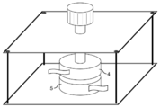
直径36mm、高さ10mmの円柱型の真鍮(JIS規格の材料番号C2600)製の電極4、電極5、及び電極4と電極5とを押圧するネジを有する治具(図2参照)を使用した。上記治具の電極4と電極5との間にフィルムを挟み、日置電機株式会社の抵抗率計「ACミリオームハイテスタ3560型」(商品名)を接続した。次にネジを締付トルク0.3N・mに達するまで更に締め込み、所定トルクに到達してから5分経過後の抵抗値を初期導電性(単位mΩ)として測定した。 Measurement and evaluation method of physical properties (i) Initial conductivity (Ω1)
A cylindrical brass (JIS standard material number C2600)electrode 4 having a diameter of 36 mm and a height of 10 mm, an electrode 5, and a jig having a screw for pressing the electrode 4 and the electrode 5 (see FIG. 2) were used. . A film was sandwiched between the electrode 4 and the electrode 5 of the jig, and a resistivity meter “AC milliohm high tester 3560 type” (trade name) manufactured by Hioki Electric Co., Ltd. was connected. Next, the screw was further tightened until a tightening torque of 0.3 N · m was reached, and the resistance value after 5 minutes from the arrival of the predetermined torque was measured as the initial conductivity (unit: mΩ).
(i)初期導電性(Ω1)
直径36mm、高さ10mmの円柱型の真鍮(JIS規格の材料番号C2600)製の電極4、電極5、及び電極4と電極5とを押圧するネジを有する治具(図2参照)を使用した。上記治具の電極4と電極5との間にフィルムを挟み、日置電機株式会社の抵抗率計「ACミリオームハイテスタ3560型」(商品名)を接続した。次にネジを締付トルク0.3N・mに達するまで更に締め込み、所定トルクに到達してから5分経過後の抵抗値を初期導電性(単位mΩ)として測定した。 Measurement and evaluation method of physical properties (i) Initial conductivity (Ω1)
A cylindrical brass (JIS standard material number C2600)
(ii)耐電解液性
常温(温度23±2℃)の硫酸バナジウム(バナジウムの酸化数は5)水溶液(濃度2.0モル/リットル)に、フィルムのマシン方向に40mm×フィルムの幅方向に40mmの大きさに裁断したフィルムを7日間浸漬し、水洗した後、フィルム表面の状態を目視観察し、以下の基準で耐電解液性を評価した。
◎:フィルム表面に変化が無かった。
○:フィルム表面に斑模様が見られた。
△:フィルム表面の一部に油膜のような虹斑が発生した。
×:フィルム表面全面に油膜のような虹斑が発生した。 (Ii) Resistance to electrolyte solution In an aqueous solution (concentration of 2.0 mol / liter) of vanadium sulfate at normal temperature (temperature 23 ± 2 ° C.) (concentration 2.0 mol / liter), 40 mm × in the width direction of the film The film cut to a size of 40 mm was immersed for 7 days and washed with water, and then the state of the film surface was visually observed, and the resistance to electrolytic solution was evaluated according to the following criteria.
A: There was no change on the film surface.
○: Spotted pattern was observed on the film surface.
(Triangle | delta): The erythema like an oil film generate | occur | produced on a part of film surface.
X: Iridae like an oil film occurred on the entire film surface.
(iii)体積抵抗率ρ
JIS K7194:1994に準拠し、4探針法(プローブ法)によりフィルムの体積抵抗率を測定した。温度23±2℃及び相対湿度50±5%の試験室において24時間以上状態調節を行ったフィルムを、フィルムのマシン方向に80mm×フィルムの幅方向に50mmの大きさに切り出して試験片とした。株式会社三菱化学アナリテックの抵抗率計「ロレスタGP MCP-T610型」(商品名)を使用し、一直線上に等間隔(探針間隔5mm)に配列したプローブを用いて、1枚の試験片について5つの測定位置において体積抵抗率の値を測定した。これを3枚の試験片について行い、合計15個の体積抵抗率の値の平均値を、このフィルムの体積抵抗率ρとした。フィルム厚みは、株式会社尾崎製作所のダイヤルシックネスゲージ「H-1A」(商品名)を用いて、JIS K7194に規定する試験片の寸法測定に従い測定した。なお、電気抵抗率測定方法及びその理論については、株式会社三菱化学アナリテックのホームページ(http://www.mccat.co.jp/3seihin/genri/ghlup2.htm)などを参照することができる。 (Iii) Volume resistivity ρ
Based on JIS K7194: 1994, the volume resistivity of the film was measured by a four-probe method (probe method). A film that had been conditioned for 24 hours or more in a test room at a temperature of 23 ± 2 ° C. and a relative humidity of 50 ± 5% was cut into a size of 80 mm in the machine direction of the film and 50 mm in the width direction of the film to obtain a test piece. . Using a resistivity meter “Loresta GP MCP-T610” (trade name) manufactured by Mitsubishi Chemical Analytech Co., Ltd., using a probe arranged at regular intervals (probe interval 5 mm) on a straight line, one test piece The volume resistivity value was measured at five measurement positions. This was performed for three test pieces, and the average value of the total 15 volume resistivity values was defined as the volume resistivity ρ of this film. The film thickness was measured using a dial thickness gauge “H-1A” (trade name) manufactured by Ozaki Mfg. Co., Ltd. according to the dimensional measurement of the test piece specified in JIS K7194. In addition, about the electrical resistivity measuring method and its theory, the homepage (http://www.mccat.co.jp/3seihin/genri/ghlup2.html) of Mitsubishi Chemical Analytech Co., Ltd. can be referred.
JIS K7194:1994に準拠し、4探針法(プローブ法)によりフィルムの体積抵抗率を測定した。温度23±2℃及び相対湿度50±5%の試験室において24時間以上状態調節を行ったフィルムを、フィルムのマシン方向に80mm×フィルムの幅方向に50mmの大きさに切り出して試験片とした。株式会社三菱化学アナリテックの抵抗率計「ロレスタGP MCP-T610型」(商品名)を使用し、一直線上に等間隔(探針間隔5mm)に配列したプローブを用いて、1枚の試験片について5つの測定位置において体積抵抗率の値を測定した。これを3枚の試験片について行い、合計15個の体積抵抗率の値の平均値を、このフィルムの体積抵抗率ρとした。フィルム厚みは、株式会社尾崎製作所のダイヤルシックネスゲージ「H-1A」(商品名)を用いて、JIS K7194に規定する試験片の寸法測定に従い測定した。なお、電気抵抗率測定方法及びその理論については、株式会社三菱化学アナリテックのホームページ(http://www.mccat.co.jp/3seihin/genri/ghlup2.htm)などを参照することができる。 (Iii) Volume resistivity ρ
Based on JIS K7194: 1994, the volume resistivity of the film was measured by a four-probe method (probe method). A film that had been conditioned for 24 hours or more in a test room at a temperature of 23 ± 2 ° C. and a relative humidity of 50 ± 5% was cut into a size of 80 mm in the machine direction of the film and 50 mm in the width direction of the film to obtain a test piece. . Using a resistivity meter “Loresta GP MCP-T610” (trade name) manufactured by Mitsubishi Chemical Analytech Co., Ltd., using a probe arranged at regular intervals (
(iv)耐折曲性
温度23±2℃および相対湿度50±5%の試験室において24時間以上状態調節を行ったフィルムから、フィルムのマシン方向が引張方向となるようにJIS K7127の試験片タイプ1Bの試験片を打抜き、試験片の両端のチャック部の全体が重なるように180°折り曲げ、折り曲げ位置を指でしごいた後、起こした。次にこれを反対側へと、同様に180°折り曲げ、折り曲げ位置を指でしごいた後、起こした。このように同じ折り曲げ位置において、折り曲げて起こし、反対側へと折り曲げて起こす操作を1セットとする操作を繰返し、以下の基準で耐折曲性を評価した。
◎:10セット終了後もフィルムは破断しなかった。
○:6セットの開始後~10セット終了後までにフィルムが破断した。
△:2セットの開始後~5セット終了後までにフィルムが破断した。
×:1セット終了後までにフィルムが破断した。 (Iv) Bending resistance A test piece of JIS K7127 from a film which has been conditioned for 24 hours or more in a test room at a temperature of 23 ± 2 ° C. and a relative humidity of 50 ± 5% so that the machine direction of the film becomes the tensile direction. A type 1B test piece was punched out, bent 180 ° so that the entire chuck portion at both ends of the test piece overlapped, and the bending position was rubbed with a finger and then raised. Next, this was bent to the opposite side in the same manner by 180 °, and the folding position was squeezed with a finger and then raised. In this way, at the same folding position, the operation of bending and raising and bending to the opposite side was repeated, and the bending resistance was evaluated according to the following criteria.
A: The film did not break even after 10 sets were completed.
○: The film broke between the start of 6 sets and the end of 10 sets.
Δ: The film broke between the start of 2 sets and the end of 5 sets.
X: The film broke by the end of the set.
(v)湿熱処理後の耐折曲性
温度60℃±2℃、相対湿度98%の恒温恒湿槽内にて7日間暴露処理を行ったフィルムから、フィルムのマシン方向が引張方向となるようにJIS K7127の試験片タイプ1Bの試験片を打抜き、試験片の両端のチャック部の全体が重なるように180°折り曲げ、折り曲げ位置を指でしごいた後、起こした。次にこれを反対側へと、同様に180°折り曲げ、折り曲げ位置を指でしごいた後、起こした。このように同じ折り曲げ位置において、折り曲げて起こし、反対側へと折り曲げて起こす操作を1セットとする操作を繰返し、以下の基準で判断した。
◎:10セット終了後もフィルムは破断しなかった。
○:6セットの開始後~10セット終了後までにフィルムが破断した。
△:2セットの開始後~5セット終了後までにフィルムが破断した。
×:1セット終了後までにフィルムが破断した。 (V) Bending resistance after wet heat treatment From the film that has been exposed for 7 days in a constant temperature and humidity chamber at a temperature of 60 ° C ± 2 ° C and a relative humidity of 98%, the machine direction of the film becomes the tensile direction. Then, a test piece of JIS K7127 test piece type 1B was punched out, bent at 180 ° so that the entire chuck portion at both ends of the test piece overlapped, and the bending position was rubbed with a finger, and then raised. Next, this was bent to the opposite side in the same manner by 180 °, and the folding position was squeezed with a finger and then raised. In this way, the operation of bending and raising at the same folding position and then bending to the opposite side was repeated, and the following criteria were used.
A: The film did not break even after 10 sets were completed.
○: The film broke between the start of 6 sets and the end of 10 sets.
Δ: The film broke between the start of 2 sets and the end of 5 sets.
X: The film broke by the end of the set.
(vi)引張伸び
JIS K7127:1999に準拠して、フィルムの引張伸びを測定した。温度23±2℃および相対湿度50±5%の試験室において24時間以上状態調節を行ったフィルムについて、株式会社島津製作所の引張試験機「AUTOGRAPH AGS-1kNG」(商品名)を用い、フィルムの幅方向を引張方向として、試験片タイプ1号ダンベル、チャック間の初期距離120mm、標線間距離50mm、引張速度5mm/分の条件で引張試験を行って破断時の伸びの値を求めた。この試験を5つの試験片について行い、これらの平均値をこのフィルムの引張伸びEとした。フィルム厚みは株式会社尾崎製作所のダイヤルシックネスゲージ「H-1A」(商品名)を用いて試験片の標線間について測定し(計10カ所)、それらの平均値を使用した。 (Vi) Tensile elongation The tensile elongation of the film was measured according to JIS K7127: 1999. For a film that has been conditioned for at least 24 hours in a test room at a temperature of 23 ± 2 ° C. and a relative humidity of 50 ± 5%, a tensile tester “AUTOGRAPH AGS-1kNG” (trade name) manufactured by Shimadzu Corporation is used. A tensile test was performed under the conditions of the test piece type No. 1 dumbbell, the initial distance between the chucks of 120 mm, the distance between the marked lines of 50 mm, and the tensile speed of 5 mm / min with the width direction as the tensile direction, and the elongation at break was determined. This test was performed on five test pieces, and the average value of these was used as the tensile elongation E of the film. The film thickness was measured between the marked lines of the test pieces using a dial thickness gauge “H-1A” (trade name) manufactured by Ozaki Mfg. Co., Ltd. (total of 10 locations), and the average value of these was used.
JIS K7127:1999に準拠して、フィルムの引張伸びを測定した。温度23±2℃および相対湿度50±5%の試験室において24時間以上状態調節を行ったフィルムについて、株式会社島津製作所の引張試験機「AUTOGRAPH AGS-1kNG」(商品名)を用い、フィルムの幅方向を引張方向として、試験片タイプ1号ダンベル、チャック間の初期距離120mm、標線間距離50mm、引張速度5mm/分の条件で引張試験を行って破断時の伸びの値を求めた。この試験を5つの試験片について行い、これらの平均値をこのフィルムの引張伸びEとした。フィルム厚みは株式会社尾崎製作所のダイヤルシックネスゲージ「H-1A」(商品名)を用いて試験片の標線間について測定し(計10カ所)、それらの平均値を使用した。 (Vi) Tensile elongation The tensile elongation of the film was measured according to JIS K7127: 1999. For a film that has been conditioned for at least 24 hours in a test room at a temperature of 23 ± 2 ° C. and a relative humidity of 50 ± 5%, a tensile tester “AUTOGRAPH AGS-1kNG” (trade name) manufactured by Shimadzu Corporation is used. A tensile test was performed under the conditions of the test piece type No. 1 dumbbell, the initial distance between the chucks of 120 mm, the distance between the marked lines of 50 mm, and the tensile speed of 5 mm / min with the width direction as the tensile direction, and the elongation at break was determined. This test was performed on five test pieces, and the average value of these was used as the tensile elongation E of the film. The film thickness was measured between the marked lines of the test pieces using a dial thickness gauge “H-1A” (trade name) manufactured by Ozaki Mfg. Co., Ltd. (total of 10 locations), and the average value of these was used.
使用した原材料
成分(A1)
(A1-1):昭和電工株式会社の塩素化ポリエチレン「エラスレン303A」(商品名)、塩素含有量32質量%、メルトフローレート(180℃、211.8N)120g/10分、融解熱量2J/g
(A1-2):昭和電工株式会社の塩素化ポリエチレン「エラスレン303B」(商品名)、塩素含有量32質量%、メルトフローレート(180℃、211.8N)25g/10分、融解熱量50J/g
(A1-3):昭和電工株式会社の塩素化ポリエチレン「エラスレン404B」(商品名)、塩素含有量40質量%、メルトフローレート(180℃、211.8N)25g/10分、融解熱量29J/g Raw materials used
Ingredient (A1)
(A1-1): Showa Denko Co., Ltd.'s chlorinated polyethylene “Elaslene 303A” (trade name), chlorine content 32 mass%, melt flow rate (180 ° C., 211.8 N) 120 g / 10 min, heat of fusion 2 J / g
(A1-2): Chlorinated polyethylene “Elaslene 303B” (trade name), Showa Denko Co., Ltd., chlorine content 32 mass%, melt flow rate (180 ° C., 211.8 N) 25 g / 10 minutes, heat of fusion 50 J / g
(A1-3): Chlorinated polyethylene “Elaslene 404B” (trade name), Showa Denko Co., Ltd., chlorine content 40 mass%, melt flow rate (180 ° C., 211.8 N) 25 g / 10 min, heat of fusion 29 J / g
成分(A2)
(A2-1):ザ・ダウ・ケミカル・カンパニーのポリエチレン「エンゲージ8402」(商品名)、メルトフローレート(190℃、21.18N)30g/10分、密度877Kg/m3、Tm-A2:99℃
(A2-2):株式会社プライムポリマーのポリエチレン「ウルトゼックス20200J」(商品名)、メルトフローレート(190℃、21.18N)18.5g/10分、密度918Kg/m3、Tm-A2:125℃ Ingredient (A2)
(A2-1): The Dow Chemical Company polyethylene “engage 8402” (trade name), melt flow rate (190 ° C., 21.18 N) 30 g / 10 min, density 877 Kg / m 3 , Tm-A2: 99 ° C
(A2-2): Prime Polymer Co., Ltd. polyethylene “Ultzex 20200J” (trade name), melt flow rate (190 ° C., 21.18 N) 18.5 g / 10 min, density 918 Kg / m 3 , Tm-A2: 125 ° C
成分(A3)
(A3-1):株式会社プライムポリマーのポリエチレン「ウルトゼックス20200J」(商品名)、メルトフローレート(190℃、21.18N)18.5g/10分、密度918Kg/m3、Tm-A3:125℃、Xc62%
(A3-2):株式会社プライムポリマーのポリエチレン「ネオゼックス2024G」(商品名)、メルトフローレート(190℃、21.18N)25g/10分、密度915Kg/m3、Tm-A3:120℃、Xc75%
(A3-3):株式会社プライムポリマーのポリエチレン「エボリューSP4530」(商品名)、メルトフローレート(190℃、21.18N)2.8g/10分、密度942Kg/m3、Tm-A3:132℃、Xc20%;と下記成分(A3’-2)との40/60(質量比)の混合物 Tm-A3:132℃、Xc68% Ingredient (A3)
(A3-1): Prime Polymer Co., Ltd. polyethylene “Ultzex 20200J” (trade name), melt flow rate (190 ° C., 21.18 N) 18.5 g / 10 min, density 918 Kg / m 3 , Tm-A3: 125 ° C, Xc 62%
(A3-2): Prime Polymer Co., Ltd. polyethylene “Neozex 2024G” (trade name), melt flow rate (190 ° C., 21.18 N) 25 g / 10 min, density 915 Kg / m 3 , Tm-A3: 120 ° C. Xc 75%
(A3-3): Prime Polymer Co., Ltd. polyethylene “Evolue SP4530” (trade name), melt flow rate (190 ° C., 21.18 N) 2.8 g / 10 min, density 942 Kg / m 3 , Tm-A3: 132 40/60 (mass ratio) of the following component (A3′-2): Tm-A3: 132 ° C., Xc 68%
比較成分(A3’)
(A3’-1):ザ・ダウ・ケミカル・カンパニーのポリエチレン「D9100.00」(商品名)、メルトフローレート(190℃、21.18N)1g/10分、密度877Kg/m3、Tm-A3:118℃、Xc29%
(A3’-2):ザ・ダウ・ケミカル・カンパニーのポリエチレン「エンゲージ8402」(商品名)、メルトフローレート(190℃、21.18N)30g/10分、密度877Kg/m3、Tm-A3:99℃、Xc100%
(A3’-3):株式会社プライムポリマーのポリエチレン「エボリューSP4530」(商品名)、メルトフローレート(190℃、21.18N)2.8g/10分、密度942Kg/m3、Tm-A3:132℃、Xc20%
(A3’-4):上記(A3’-1)と上記(A3’-2)との50/50(質量比)の混合物 Tm-A3:118℃、Xc65% Comparative component (A3 ′)
(A3′-1): The Dow Chemical Company polyethylene “D9100.00” (trade name), melt flow rate (190 ° C., 21.18 N) 1 g / 10 min, density 877 Kg / m 3 , Tm— A3: 118 ° C., Xc 29%
(A3′-2): The Dow Chemical Company polyethylene “engage 8402” (trade name), melt flow rate (190 ° C., 21.18 N) 30 g / 10 min, density 877 Kg / m 3 , Tm-A3 : 99 ° C, Xc 100%
(A3′-3): Prime Polymer Co., Ltd. polyethylene “Evolue SP4530” (trade name), melt flow rate (190 ° C., 21.18 N) 2.8 g / 10 min, density 942 Kg / m 3 , Tm-A3: 132 ° C, Xc 20%
(A3′-4): 50/50 (mass ratio) mixture of the above (A3′-1) and the above (A3′-2) Tm-A3: 118 ° C., Xc 65%
成分(B)
(B-1):ナノシルS.A.社の多層カーボンナノチューブ「ナノシルNC7000」(商品名)、平均直径9.5nm、平均長1.5μm、嵩比重0.043g/cm3、純度90質量% Ingredient (B)
(B-1): Nanosil S.I. A. Multi-walled carbon nanotube “Nanosil NC7000” (trade name), average diameter 9.5 nm, average length 1.5 μm, bulk specific gravity 0.043 g / cm 3 , purity 90% by mass
(B-1):ナノシルS.A.社の多層カーボンナノチューブ「ナノシルNC7000」(商品名)、平均直径9.5nm、平均長1.5μm、嵩比重0.043g/cm3、純度90質量% Ingredient (B)
(B-1): Nanosil S.I. A. Multi-walled carbon nanotube “Nanosil NC7000” (trade name), average diameter 9.5 nm, average length 1.5 μm, bulk specific gravity 0.043 g / cm 3 , purity 90% by mass
成分(C)
(C-1):電気化学工業株式会社のアセチレンブラック「デンカブラック粒状」(商品名)、一次粒子の平均粒子径35nm(電子顕微鏡(TEM)観察により測定)、比表面積69m2/g Ingredient (C)
(C-1): Acetylene black “Denka Black Granule” (trade name) manufactured by Denki Kagaku Kogyo Co., Ltd., average particle diameter of primary particles 35 nm (measured by observation with an electron microscope (TEM)), specific surface area 69 m 2 / g
比較成分(C’)
(C’-1):ライオン株式会社のケッチェンブラック「KJ300」(商品名) Comparative component (C ')
(C'-1): Lion Corporation Ketjen Black "KJ300" (trade name)
(C’-1):ライオン株式会社のケッチェンブラック「KJ300」(商品名) Comparative component (C ')
(C'-1): Lion Corporation Ketjen Black "KJ300" (trade name)
成分(D):任意成分
(D-1):日東化成工業株式会社の塩素化ポリエチレン用安定剤「STANN JF-95B」(商品名) Component (D): Optional component (D-1): Stabilizer for chlorinated polyethylene “STANN JF-95B” (trade name) manufactured by Nitto Kasei Kogyo Co., Ltd.
(D-1):日東化成工業株式会社の塩素化ポリエチレン用安定剤「STANN JF-95B」(商品名) Component (D): Optional component (D-1): Stabilizer for chlorinated polyethylene “STANN JF-95B” (trade name) manufactured by Nitto Kasei Kogyo Co., Ltd.
フィルムの形成及び物性の測定・評価
日本ロール製造株式会社の5リットルインテンシブミキサーを使用し、表1~3に示される成分比率の諸例の配合物を溶融混練した。このとき排出温度は190℃とした。続いて、日本ロール製造株式会社のロール直径200mm、ロール幅700mmの逆L型4本ロール圧延カレンダーを使用し、厚み300μmのフィルムを得た(ロール温度:第一ロール/第二ロール/第三ロール/第四ロールの順に205℃/205℃/185℃/175℃、引取速度:5m/分)。得られたフィルムについて、上記試験(i)~(vi)を行った。結果を表1~3に示す。 Formation of Film and Measurement / Evaluation of Physical Properties Using a 5-liter intensive mixer manufactured by Nippon Roll Manufacturing Co., Ltd., blends of various examples of component ratios shown in Tables 1 to 3 were melt-kneaded. At this time, the discharge temperature was 190 ° C. Subsequently, a reverse L-type four-roll rolling calender with a roll diameter of 200 mm and a roll width of 700 mm manufactured by Nippon Roll Manufacturing Co., Ltd. was used to obtain a film having a thickness of 300 μm (roll temperature: first roll / second roll / third (205 ° C / 205 ° C / 185 ° C / 175 ° C in order of roll / fourth roll, take-up speed: 5 m / min). The obtained film was subjected to the above tests (i) to (vi). The results are shown in Tables 1 to 3.
日本ロール製造株式会社の5リットルインテンシブミキサーを使用し、表1~3に示される成分比率の諸例の配合物を溶融混練した。このとき排出温度は190℃とした。続いて、日本ロール製造株式会社のロール直径200mm、ロール幅700mmの逆L型4本ロール圧延カレンダーを使用し、厚み300μmのフィルムを得た(ロール温度:第一ロール/第二ロール/第三ロール/第四ロールの順に205℃/205℃/185℃/175℃、引取速度:5m/分)。得られたフィルムについて、上記試験(i)~(vi)を行った。結果を表1~3に示す。 Formation of Film and Measurement / Evaluation of Physical Properties Using a 5-liter intensive mixer manufactured by Nippon Roll Manufacturing Co., Ltd., blends of various examples of component ratios shown in Tables 1 to 3 were melt-kneaded. At this time, the discharge temperature was 190 ° C. Subsequently, a reverse L-type four-roll rolling calender with a roll diameter of 200 mm and a roll width of 700 mm manufactured by Nippon Roll Manufacturing Co., Ltd. was used to obtain a film having a thickness of 300 μm (roll temperature: first roll / second roll / third (205 ° C / 205 ° C / 185 ° C / 175 ° C in order of roll / fourth roll, take-up speed: 5 m / min). The obtained film was subjected to the above tests (i) to (vi). The results are shown in Tables 1 to 3.


各実施例にて得られた結果から分かるように、本発明の樹脂組成物から形成されたフィルムは、耐電解液性、体積抵抗率、耐折曲性、湿熱処理後の耐折曲性、及び引張伸びの諸特性が、高いレベルでバランス良く発現していた。また、実施例4及び実施例8以外の各実施例では、初期導電性も優れていた。実施例4及び実施例8(いずれもメルトフローレートが(A1-1)よりも低くかつ結晶性である(A1-2)又は(A1-3)が用いられた)では、十分に良好な初期導電性が得られなかった一方で、低い体積抵抗率が得られたため、他の諸特性に加えて導電性の観点からも実用に足るフィルムが得られたものと評価できる。
As can be seen from the results obtained in each example, the film formed from the resin composition of the present invention is resistant to electrolytic solution, volume resistivity, bending resistance, bending resistance after wet heat treatment, In addition, various properties of tensile elongation were expressed at a high level in a well-balanced manner. Moreover, in each Example other than Example 4 and Example 8, initial conductivity was also excellent. In Example 4 and Example 8 (both melt flow rates were lower than (A1-1) and crystalline (A1-2) or (A1-3) were used), a sufficiently good initial Since conductivity was not obtained, but low volume resistivity was obtained, it can be evaluated that a film sufficient for practical use was obtained from the viewpoint of conductivity in addition to other characteristics.
一方、比較例1は成分(A2)の量が多く、湿熱処理後の耐折曲性が不十分であった。比較例2は成分(A2)の量が少なく、耐電解液性に劣っていた。比較例3~5は成分(C)を用いていない例である。成分(B)の少ないときは、初期導電性が実施例1や7に及ばず、成分(B)の多いときは、耐折曲性や湿熱処理後の耐折曲性が不十分であるか、劣るものになっていた。比較例6は成分(B)を用いていないため、初期導電性に劣り、体積抵抗率が大きかった。また耐折曲性や湿熱処理後の耐折曲性にも劣っていた。比較例7は成分(C)の替わりにケッチェンブラックを用いた例であるが、製膜することができなかった。そのため試験(i)~(vi)は省略した。比較例8はTm-A3が低く、Xcも低いため、耐電解液性に劣り、耐折曲性や湿熱処理後の耐折曲性が不十分であった。比較例9はTm-A3が低く、Xcが高いため、耐折曲性や湿熱処理後の耐折曲性に劣っていた。Tm-A3及びXcのいずれか一方が所定の範囲外である(A3’-3)又は(A3’-4)が用いられた比較例10及び11では、やはり耐電解液性、耐折曲性及び湿熱処理後の耐折曲性が劣っていた。
On the other hand, Comparative Example 1 had a large amount of component (A2), and the bending resistance after wet heat treatment was insufficient. In Comparative Example 2, the amount of the component (A2) was small and the electrolytic solution resistance was poor. Comparative Examples 3 to 5 are examples in which component (C) is not used. When the component (B) is small, the initial conductivity does not reach that of Examples 1 and 7. When the component (B) is large, is the bending resistance or the bending resistance after wet heat treatment insufficient? It was inferior. Since Comparative Example 6 did not use the component (B), the initial conductivity was inferior and the volume resistivity was large. Moreover, the bending resistance and the bending resistance after wet heat treatment were also inferior. Although the comparative example 7 is an example using Ketjen black instead of the component (C), it could not be formed into a film. Therefore, tests (i) to (vi) were omitted. Since Comparative Example 8 had a low Tm-A3 and a low Xc, it was inferior in electrolytic solution resistance, and had insufficient bending resistance and bending resistance after wet heat treatment. Since Comparative Example 9 had a low Tm-A3 and a high Xc, the bending resistance and the bending resistance after wet heat treatment were inferior. In Comparative Examples 10 and 11 in which (A3′-3) or (A3′-4) in which either one of Tm-A3 and Xc is outside the predetermined range is used, the resistance to electrolytic solution and the resistance to bending are still the same. And the bending resistance after wet heat treatment was inferior.
本発明による樹脂組成物から形成されたフィルムは、蓄電池の電極部材、特に電解液循環型二次電池、例えば、レドックスフロー電池、亜鉛・塩素電池、及び亜鉛・臭素電池等における電極又はその被覆保護に好適に用いることができる。
The film formed from the resin composition according to the present invention is an electrode member of a storage battery, particularly an electrode in an electrolyte circulation type secondary battery, such as a redox flow battery, a zinc / chlorine battery, and a zinc / bromine battery, or a coating protection thereof. Can be suitably used.
1:DSCのセカンド融解曲線での最も高い温度側のピークトップ融点
2:DSCのセカンド融解曲線での温度110℃以下の融解エンタルピーの積算
3:DSCのセカンド融解曲線での温度110℃の境界線
4:電極
5:電極 1: Peak top melting point on the highest temperature side in the second melting curve of DSC 2: Integration of melting enthalpies of 110 ° C. or lower in the second melting curve of DSC 3: Boundary line of temperature 110 ° C. in the second melting curve of DSC 4: Electrode 5: Electrode
Claims (7)
- (A)熱可塑性樹脂100質量部;
(B)カーボンナノチューブ1~60質量部;及び
(C)アセチレンブラック1~60質量部
を含み、
上記(A)熱可塑性樹脂は、
(A1)塩素含有量20~45質量%の塩素化ポリエチレン30~80質量%と、
(A2)上記(A1)とは異なるポリエチレン70~20質量%とからなり、
ここで(A1)と(A2)との和は100質量%であること
を特徴とする樹脂組成物。 (A) 100 parts by mass of a thermoplastic resin;
(B) 1 to 60 parts by mass of carbon nanotubes; and (C) 1 to 60 parts by mass of acetylene black,
The (A) thermoplastic resin is
(A1) 30-80% by mass of chlorinated polyethylene having a chlorine content of 20-45% by mass;
(A2) comprising 70 to 20% by mass of polyethylene different from the above (A1),
Here, the sum of (A1) and (A2) is 100 mass%, The resin composition characterized by the above-mentioned. - (A)熱可塑性樹脂100質量部;
(B)カーボンナノチューブ1~60質量部;及び
(C)アセチレンブラック1~60質量部
を含み、
上記(A)熱可塑性樹脂は、
(A3)下記特性(p)及び(q)を満たすポリエチレンであること
を特徴とする樹脂組成物:
(p)DSC融解曲線における最も高い温度側のピークトップ融点が、120℃以上であること;及び
(q)DSC融解曲線における全融解エンタルピーに対する温度110℃以下の融解エンタルピーの割合が50~80%であること。 (A) 100 parts by mass of a thermoplastic resin;
(B) 1 to 60 parts by mass of carbon nanotubes; and (C) 1 to 60 parts by mass of acetylene black,
The (A) thermoplastic resin is
(A3) A resin composition characterized by being a polyethylene satisfying the following characteristics (p) and (q):
(P) The peak top melting point on the highest temperature side in the DSC melting curve is 120 ° C. or higher; and (q) The ratio of the melting enthalpy at a temperature of 110 ° C. or lower to the total melting enthalpy in the DSC melting curve is 50 to 80%. Be. - 上記成分(A2)のDSC融解曲線における最も高い温度側のピークトップ融点が、110℃以下であることを特徴とする請求項1に記載の樹脂組成物。 The resin composition according to claim 1, wherein the peak top melting point on the highest temperature side in the DSC melting curve of the component (A2) is 110 ° C or lower.
- 上記成分(A1)が非結晶性であることを特徴とする請求項1に記載の樹脂組成物。 The resin composition according to claim 1, wherein the component (A1) is non-crystalline.
- 請求項1~4の何れか1項に記載の樹脂組成物を含む蓄電池の電極部材。 An electrode member for a storage battery comprising the resin composition according to any one of claims 1 to 4.
- 請求項1~4の何れか1項に記載の樹脂組成物を含むフィルム。 A film comprising the resin composition according to any one of claims 1 to 4.
- 請求項6に記載のフィルムを含む蓄電池の電極部材。 A storage battery electrode member comprising the film according to claim 6.
Priority Applications (3)
| Application Number | Priority Date | Filing Date | Title |
|---|---|---|---|
| EP17194804.5A EP3284782B1 (en) | 2013-09-10 | 2014-08-12 | Electrically conductive resin composition, and film produced from same |
| EP14844477.1A EP3045497B1 (en) | 2013-09-10 | 2014-08-12 | Electrically conductive resin composition, and film produced from same |
| US15/021,188 US9748017B2 (en) | 2013-09-10 | 2014-08-12 | Electrically conductive resin composition, and film produced from same |
Applications Claiming Priority (2)
| Application Number | Priority Date | Filing Date | Title |
|---|---|---|---|
| JP2013-187524 | 2013-09-10 | ||
| JP2013187524 | 2013-09-10 |
Publications (1)
| Publication Number | Publication Date |
|---|---|
| WO2015037383A1 true WO2015037383A1 (en) | 2015-03-19 |
Family
ID=52665502
Family Applications (1)
| Application Number | Title | Priority Date | Filing Date |
|---|---|---|---|
| PCT/JP2014/071286 WO2015037383A1 (en) | 2013-09-10 | 2014-08-12 | Electrically conductive resin composition, and film produced from same |
Country Status (5)
| Country | Link |
|---|---|
| US (1) | US9748017B2 (en) |
| EP (2) | EP3284782B1 (en) |
| JP (1) | JP6385197B2 (en) |
| TW (1) | TWI633145B (en) |
| WO (1) | WO2015037383A1 (en) |
Cited By (6)
| Publication number | Priority date | Publication date | Assignee | Title |
|---|---|---|---|---|
| JP5983850B1 (en) * | 2015-11-18 | 2016-09-06 | 東洋インキScホールディングス株式会社 | Conductive resin composition, molded article and method for producing the same |
| JP2017141370A (en) * | 2016-02-10 | 2017-08-17 | デンカ株式会社 | Conductive polymer material and molded article using the same |
| US9748017B2 (en) | 2013-09-10 | 2017-08-29 | Riken Technos Corporation | Electrically conductive resin composition, and film produced from same |
| JP2017186440A (en) * | 2016-04-05 | 2017-10-12 | 東洋インキScホールディングス株式会社 | Conductive resin composition and production method of molded article |
| JP2018028031A (en) * | 2016-08-19 | 2018-02-22 | 東洋インキScホールディングス株式会社 | Conductive resin composition, molded article, and method for producing the same |
| US10767035B2 (en) | 2014-10-09 | 2020-09-08 | Riken Technos Corporation | Method for producing thermoplastic resin composition film |
Families Citing this family (3)
| Publication number | Priority date | Publication date | Assignee | Title |
|---|---|---|---|---|
| CN108136375B (en) * | 2015-08-17 | 2021-09-03 | 电化株式会社 | Method for producing carbon nanofiber composite and carbon nanofiber composite |
| CN108155342A (en) * | 2017-12-28 | 2018-06-12 | 上海君屹工业自动化股份有限公司 | Dynamic lithium battery lug apparatus for bending |
| JP7264453B2 (en) * | 2019-04-18 | 2023-04-25 | イイダ産業株式会社 | Resin-based fire-resistant composition |
Citations (15)
| Publication number | Priority date | Publication date | Assignee | Title |
|---|---|---|---|---|
| JPS62205144A (en) * | 1986-03-04 | 1987-09-09 | Mitsubishi Plastics Ind Ltd | Electrically conductive sheet |
| JPS62256847A (en) * | 1986-05-01 | 1987-11-09 | Furukawa Electric Co Ltd:The | Electrically conductive composition |
| JPS63307605A (en) * | 1987-06-09 | 1988-12-15 | Fujikura Ltd | Semiconductive admixture |
| JPH01149370A (en) | 1987-12-04 | 1989-06-12 | Meidensha Corp | Plastic electrode |
| JPH0329210A (en) * | 1989-06-26 | 1991-02-07 | Fujikura Ltd | Electric power cable |
| JPH04259754A (en) | 1991-02-15 | 1992-09-16 | Meidensha Corp | Carbon plastic electrode |
| JPH0753813A (en) | 1993-08-10 | 1995-02-28 | Shin Etsu Polymer Co Ltd | Electrically conductive plastic composition |
| JP2000357419A (en) * | 1999-05-13 | 2000-12-26 | Union Carbide Chem & Plast Technol Corp | Semiconductive shield for cable |
| JP2001015144A (en) | 1999-06-29 | 2001-01-19 | Sumitomo Electric Ind Ltd | Cell carbon plate for redox flow cell and cell structure |
| JP2004207097A (en) * | 2002-12-26 | 2004-07-22 | Inoac Corp | Conductive resin composition |
| JP2006111870A (en) | 2004-09-14 | 2006-04-27 | Showa Denko Kk | Electrically-conductive resin composition, method for producing the same, and use of the same |
| JP2009521535A (en) * | 2005-08-08 | 2009-06-04 | キャボット コーポレイション | Polymer composition comprising nanotubes |
| JP2012507586A (en) | 2008-11-06 | 2012-03-29 | クラリアント・ファイナンス・(ビーブイアイ)・リミテッド | Composition comprising propylene-propylene-copolymer wax and carbon black |
| JP2012507587A (en) | 2008-11-06 | 2012-03-29 | クラリアント・ファイナンス・(ビーブイアイ)・リミテッド | Composition comprising propylene-olefin-copolymer wax and carbon nanotubes |
| WO2013153969A1 (en) * | 2012-04-09 | 2013-10-17 | リケンテクノス株式会社 | Resin composition |
Family Cites Families (20)
| Publication number | Priority date | Publication date | Assignee | Title |
|---|---|---|---|---|
| JPH08259767A (en) | 1995-03-20 | 1996-10-08 | Sumitomo Electric Ind Ltd | Conductive plastic plate and cell using the same |
| JPH09262855A (en) | 1996-03-29 | 1997-10-07 | Ishikawajima Harima Heavy Ind Co Ltd | Method for controlling temperature of calender and apparatus therefor |
| JPH1067866A (en) | 1996-08-29 | 1998-03-10 | Shin Etsu Chem Co Ltd | Water-stopping sheet and water-barrier sheet for civil engineering |
| JP3948217B2 (en) | 2000-06-05 | 2007-07-25 | 昭和電工株式会社 | Conductive curable resin composition, cured product thereof, and molded product thereof |
| JP2003182763A (en) | 2001-12-19 | 2003-07-03 | Japan Steel Works Ltd:The | Embossed carrier tape and apparatus for continuously producing the tape |
| US20050070658A1 (en) | 2003-09-30 | 2005-03-31 | Soumyadeb Ghosh | Electrically conductive compositions, methods of manufacture thereof and articles derived from such compositions |
| JP2005200620A (en) | 2003-12-15 | 2005-07-28 | Bridgestone Corp | Thermoplastic resin composition and thermoplastic resin molded product |
| KR20070110531A (en) | 2005-04-04 | 2007-11-19 | 쇼와 덴코 가부시키가이샤 | Electrically conducting curable resin composition, cured product thereof and molded article of the same |
| JP4904526B2 (en) | 2006-09-07 | 2012-03-28 | 東レペフ加工品株式会社 | Polyolefin-based resin laminate foam having deodorizing function, and cylindrical body or molded body comprising the same |
| JP5018460B2 (en) | 2007-12-26 | 2012-09-05 | 東洋インキScホールディングス株式会社 | Carbon nanotube dispersion, resin composition using the same, and molded article |
| KR101003345B1 (en) | 2008-08-19 | 2010-12-22 | 제일모직주식회사 | Thermoplastic Resin Composition Having Excellent Electrical Conductivity, Anti-Wear Property and High Heat Resistance |
| CN102227782B (en) | 2008-09-30 | 2014-03-12 | 保土谷化学工业株式会社 | Composite material containing carbon fiber |
| KR101267272B1 (en) | 2008-12-30 | 2013-05-23 | 제일모직주식회사 | Resin composition |
| US7939167B2 (en) | 2008-12-30 | 2011-05-10 | Cheil Industries Inc. | Resin composition |
| JP2011228059A (en) | 2010-04-16 | 2011-11-10 | Sumitomo Electric Ind Ltd | Dipole plate for redox flow battery |
| TWI405802B (en) | 2010-06-24 | 2013-08-21 | Nat Univ Tsing Hua | Method for fabrication of functionalized graphene reinforced composite conducting plate |
| JP5672124B2 (en) * | 2011-04-11 | 2015-02-18 | 住友電気工業株式会社 | Bipolar plate for redox flow battery and manufacturing method thereof |
| CN102324492B (en) * | 2011-05-25 | 2013-11-27 | 深圳市金钒能源科技有限公司 | Composite conductive electrode and manufacturing method thereof |
| CN104428928B (en) * | 2012-07-13 | 2018-04-13 | 古河电气工业株式会社 | Collector, electrode, secondary cell and capacitor |
| WO2015037383A1 (en) | 2013-09-10 | 2015-03-19 | リケンテクノス株式会社 | Electrically conductive resin composition, and film produced from same |
-
2014
- 2014-08-12 WO PCT/JP2014/071286 patent/WO2015037383A1/en active Application Filing
- 2014-08-12 EP EP17194804.5A patent/EP3284782B1/en active Active
- 2014-08-12 EP EP14844477.1A patent/EP3045497B1/en active Active
- 2014-08-12 US US15/021,188 patent/US9748017B2/en active Active
- 2014-08-20 JP JP2014167131A patent/JP6385197B2/en active Active
- 2014-09-05 TW TW103130765A patent/TWI633145B/en active
Patent Citations (15)
| Publication number | Priority date | Publication date | Assignee | Title |
|---|---|---|---|---|
| JPS62205144A (en) * | 1986-03-04 | 1987-09-09 | Mitsubishi Plastics Ind Ltd | Electrically conductive sheet |
| JPS62256847A (en) * | 1986-05-01 | 1987-11-09 | Furukawa Electric Co Ltd:The | Electrically conductive composition |
| JPS63307605A (en) * | 1987-06-09 | 1988-12-15 | Fujikura Ltd | Semiconductive admixture |
| JPH01149370A (en) | 1987-12-04 | 1989-06-12 | Meidensha Corp | Plastic electrode |
| JPH0329210A (en) * | 1989-06-26 | 1991-02-07 | Fujikura Ltd | Electric power cable |
| JPH04259754A (en) | 1991-02-15 | 1992-09-16 | Meidensha Corp | Carbon plastic electrode |
| JPH0753813A (en) | 1993-08-10 | 1995-02-28 | Shin Etsu Polymer Co Ltd | Electrically conductive plastic composition |
| JP2000357419A (en) * | 1999-05-13 | 2000-12-26 | Union Carbide Chem & Plast Technol Corp | Semiconductive shield for cable |
| JP2001015144A (en) | 1999-06-29 | 2001-01-19 | Sumitomo Electric Ind Ltd | Cell carbon plate for redox flow cell and cell structure |
| JP2004207097A (en) * | 2002-12-26 | 2004-07-22 | Inoac Corp | Conductive resin composition |
| JP2006111870A (en) | 2004-09-14 | 2006-04-27 | Showa Denko Kk | Electrically-conductive resin composition, method for producing the same, and use of the same |
| JP2009521535A (en) * | 2005-08-08 | 2009-06-04 | キャボット コーポレイション | Polymer composition comprising nanotubes |
| JP2012507586A (en) | 2008-11-06 | 2012-03-29 | クラリアント・ファイナンス・(ビーブイアイ)・リミテッド | Composition comprising propylene-propylene-copolymer wax and carbon black |
| JP2012507587A (en) | 2008-11-06 | 2012-03-29 | クラリアント・ファイナンス・(ビーブイアイ)・リミテッド | Composition comprising propylene-olefin-copolymer wax and carbon nanotubes |
| WO2013153969A1 (en) * | 2012-04-09 | 2013-10-17 | リケンテクノス株式会社 | Resin composition |
Non-Patent Citations (2)
| Title |
|---|
| See also references of EP3045497A4 |
| TAKASE HIROFUMI: "Technology of distribution and evaluation method of carbon-nanotubes", JOURNAL OF THE JAPAN SOCIETY OF POLYMER PROCESSING, vol. 18, no. 9, 2006, pages 646 - 652 |
Cited By (6)
| Publication number | Priority date | Publication date | Assignee | Title |
|---|---|---|---|---|
| US9748017B2 (en) | 2013-09-10 | 2017-08-29 | Riken Technos Corporation | Electrically conductive resin composition, and film produced from same |
| US10767035B2 (en) | 2014-10-09 | 2020-09-08 | Riken Technos Corporation | Method for producing thermoplastic resin composition film |
| JP5983850B1 (en) * | 2015-11-18 | 2016-09-06 | 東洋インキScホールディングス株式会社 | Conductive resin composition, molded article and method for producing the same |
| JP2017141370A (en) * | 2016-02-10 | 2017-08-17 | デンカ株式会社 | Conductive polymer material and molded article using the same |
| JP2017186440A (en) * | 2016-04-05 | 2017-10-12 | 東洋インキScホールディングス株式会社 | Conductive resin composition and production method of molded article |
| JP2018028031A (en) * | 2016-08-19 | 2018-02-22 | 東洋インキScホールディングス株式会社 | Conductive resin composition, molded article, and method for producing the same |
Also Published As
| Publication number | Publication date |
|---|---|
| US20160225484A1 (en) | 2016-08-04 |
| EP3045497A1 (en) | 2016-07-20 |
| US9748017B2 (en) | 2017-08-29 |
| JP2015078344A (en) | 2015-04-23 |
| EP3045497A4 (en) | 2017-07-26 |
| EP3284782B1 (en) | 2022-07-27 |
| EP3045497B1 (en) | 2020-03-25 |
| EP3284782A1 (en) | 2018-02-21 |
| TW201518372A (en) | 2015-05-16 |
| TWI633145B (en) | 2018-08-21 |
| JP6385197B2 (en) | 2018-09-05 |
Similar Documents
| Publication | Publication Date | Title |
|---|---|---|
| JP6184056B2 (en) | Resin composition | |
| JP6385197B2 (en) | Conductive resin composition and film thereof | |
| JP6453026B2 (en) | Method for producing thermoplastic resin composition film | |
| JP6023548B2 (en) | Method for producing conductive continuous porous film | |
| JP6780835B2 (en) | Resin composition, method for producing resin composition, powdery mixture, bipolar plate for redox flow battery, and separator for fuel cell | |
| JPWO2010050219A1 (en) | GAS DIFFUSION LAYER FOR FUEL CELL AND METHOD FOR PRODUCING THE SAME, MEMBRANE ELECTRODE ASSEMBLY, AND FUEL CELL | |
| JP5500300B1 (en) | Sheet, electrode and fuel cell | |
| JP6246264B2 (en) | Resin composition | |
| JP2009231034A (en) | Fuel cell separator, and its manufacturing method | |
| JP2004168897A (en) | Highly electroconductive resin molded product | |
| WO2017150470A1 (en) | Resin porous membrane and production method therefor | |
| Bouatia et al. | Development and characterisation of electrically conductive polymeric‐based blends for proton exchange membrane fuel cell bipolar plates | |
| TWI585139B (en) | Resin composition and conductive resin film | |
| JP2005100703A (en) | Conductive molding material, separator using it for fuel cell, and method of manufacturing the same | |
| CN104245852B (en) | Resin combination and electroconductive resin film | |
| KR20230149759A (en) | Conductive material masterbatch and dry electrode prepared by using the same | |
| JP6177011B2 (en) | Method for producing conductive communicating porous material |
Legal Events
| Date | Code | Title | Description |
|---|---|---|---|
| 121 | Ep: the epo has been informed by wipo that ep was designated in this application |
Ref document number: 14844477 Country of ref document: EP Kind code of ref document: A1 |
|
| REEP | Request for entry into the european phase |
Ref document number: 2014844477 Country of ref document: EP |
|
| WWE | Wipo information: entry into national phase |
Ref document number: 2014844477 Country of ref document: EP |
|
| NENP | Non-entry into the national phase |
Ref country code: DE |
|
| WWE | Wipo information: entry into national phase |
Ref document number: 15021188 Country of ref document: US |