WO2012063681A1 - Carbon catalyst and process for production thereof, and electrode and battery each equipped with same - Google Patents
Carbon catalyst and process for production thereof, and electrode and battery each equipped with same Download PDFInfo
- Publication number
- WO2012063681A1 WO2012063681A1 PCT/JP2011/075187 JP2011075187W WO2012063681A1 WO 2012063681 A1 WO2012063681 A1 WO 2012063681A1 JP 2011075187 W JP2011075187 W JP 2011075187W WO 2012063681 A1 WO2012063681 A1 WO 2012063681A1
- Authority
- WO
- WIPO (PCT)
- Prior art keywords
- carbon catalyst
- catalyst
- metal
- carbon
- copper
- Prior art date
Links
Images


Classifications
-
- H—ELECTRICITY
- H01—ELECTRIC ELEMENTS
- H01M—PROCESSES OR MEANS, e.g. BATTERIES, FOR THE DIRECT CONVERSION OF CHEMICAL ENERGY INTO ELECTRICAL ENERGY
- H01M4/00—Electrodes
- H01M4/86—Inert electrodes with catalytic activity, e.g. for fuel cells
- H01M4/90—Selection of catalytic material
- H01M4/9041—Metals or alloys
-
- B—PERFORMING OPERATIONS; TRANSPORTING
- B01—PHYSICAL OR CHEMICAL PROCESSES OR APPARATUS IN GENERAL
- B01J—CHEMICAL OR PHYSICAL PROCESSES, e.g. CATALYSIS OR COLLOID CHEMISTRY; THEIR RELEVANT APPARATUS
- B01J23/00—Catalysts comprising metals or metal oxides or hydroxides, not provided for in group B01J21/00
- B01J23/70—Catalysts comprising metals or metal oxides or hydroxides, not provided for in group B01J21/00 of the iron group metals or copper
- B01J23/74—Iron group metals
- B01J23/745—Iron
-
- B—PERFORMING OPERATIONS; TRANSPORTING
- B01—PHYSICAL OR CHEMICAL PROCESSES OR APPARATUS IN GENERAL
- B01J—CHEMICAL OR PHYSICAL PROCESSES, e.g. CATALYSIS OR COLLOID CHEMISTRY; THEIR RELEVANT APPARATUS
- B01J23/00—Catalysts comprising metals or metal oxides or hydroxides, not provided for in group B01J21/00
- B01J23/70—Catalysts comprising metals or metal oxides or hydroxides, not provided for in group B01J21/00 of the iron group metals or copper
- B01J23/74—Iron group metals
- B01J23/75—Cobalt
-
- H—ELECTRICITY
- H01—ELECTRIC ELEMENTS
- H01M—PROCESSES OR MEANS, e.g. BATTERIES, FOR THE DIRECT CONVERSION OF CHEMICAL ENERGY INTO ELECTRICAL ENERGY
- H01M4/00—Electrodes
- H01M4/86—Inert electrodes with catalytic activity, e.g. for fuel cells
- H01M4/88—Processes of manufacture
-
- H—ELECTRICITY
- H01—ELECTRIC ELEMENTS
- H01M—PROCESSES OR MEANS, e.g. BATTERIES, FOR THE DIRECT CONVERSION OF CHEMICAL ENERGY INTO ELECTRICAL ENERGY
- H01M4/00—Electrodes
- H01M4/86—Inert electrodes with catalytic activity, e.g. for fuel cells
- H01M4/96—Carbon-based electrodes
-
- H—ELECTRICITY
- H01—ELECTRIC ELEMENTS
- H01M—PROCESSES OR MEANS, e.g. BATTERIES, FOR THE DIRECT CONVERSION OF CHEMICAL ENERGY INTO ELECTRICAL ENERGY
- H01M8/00—Fuel cells; Manufacture thereof
- H01M8/10—Fuel cells with solid electrolytes
-
- H—ELECTRICITY
- H01—ELECTRIC ELEMENTS
- H01M—PROCESSES OR MEANS, e.g. BATTERIES, FOR THE DIRECT CONVERSION OF CHEMICAL ENERGY INTO ELECTRICAL ENERGY
- H01M8/00—Fuel cells; Manufacture thereof
- H01M8/10—Fuel cells with solid electrolytes
- H01M2008/1095—Fuel cells with polymeric electrolytes
-
- Y—GENERAL TAGGING OF NEW TECHNOLOGICAL DEVELOPMENTS; GENERAL TAGGING OF CROSS-SECTIONAL TECHNOLOGIES SPANNING OVER SEVERAL SECTIONS OF THE IPC; TECHNICAL SUBJECTS COVERED BY FORMER USPC CROSS-REFERENCE ART COLLECTIONS [XRACs] AND DIGESTS
- Y02—TECHNOLOGIES OR APPLICATIONS FOR MITIGATION OR ADAPTATION AGAINST CLIMATE CHANGE
- Y02E—REDUCTION OF GREENHOUSE GAS [GHG] EMISSIONS, RELATED TO ENERGY GENERATION, TRANSMISSION OR DISTRIBUTION
- Y02E60/00—Enabling technologies; Technologies with a potential or indirect contribution to GHG emissions mitigation
- Y02E60/30—Hydrogen technology
- Y02E60/50—Fuel cells
Definitions
- the present invention relates to a carbon catalyst, a method for producing the same, and an electrode and a battery using the carbon catalyst, and particularly relates to an improvement in catalytic activity of the carbon catalyst.
- platinum catalysts are used in many chemical reactions and next-generation batteries.
- the reserves of platinum are limited, the use of platinum in polymer electrolyte fuel cells (PEFC) increases costs, and the use of platinum in air batteries only increases costs.
- PEFC polymer electrolyte fuel cells
- Patent Document 1 a metal oxide such as ruthenium oxide, titanium oxide, vanadium oxide, manganese oxide, cobalt oxide, nickel oxide, tungsten oxide, or metal nitride such as molybdenum nitride is used as an electrode catalyst.
- the proposed fuel cell has been proposed.
- Patent Document 2 it is obtained by the carbonization process by baking after adding and mixing the metal compound containing at least 1 of iron, cobalt, nickel, chromium, or manganese to the raw material which produces
- Patent Document 3 proposes a fuel cell carbon catalyst having a nano-sized shell-like structure as described in Patent Document 2 and having nitrogen introduced by a liquid phase doping method or a gas phase doping method. Has been.
- the electrode catalyst using the metal oxide or metal nitride proposed in Patent Document 1 has a problem that its catalytic activity is low. Moreover, although the carbon catalyst proposed by the said patent document 2 and the patent document 3 shows comparatively high catalyst activity, the catalyst activity was not enough. Moreover, in the conventional carbon catalyst, it was difficult to control appropriately the structure required in order to show high catalyst activity.
- a metal cluster is formed in the raw material at a relatively low temperature, and the temperature is carbonized in the carbonization of the raw material. By the time the temperature reaches the temperature, the metal clusters agglomerate. As a result, the shell-like structure formed around the agglomerated metal clusters is enlarged by carbonization, and the surface defects of the carbon structure contributing to the catalytic activity disappear. This is thought to be caused by
- the carbon catalyst in order for the carbon catalyst to exhibit high catalytic activity, it is considered important that the carbon catalyst contains an appropriate amount of nitrogen atoms.
- cobalt or iron suitable for the development of a shell-like structure has been preferably used as the metal contained in the raw material of the carbon catalyst.
- the development of the shell-like structure using cobalt or iron is a carbon catalyst.
- causes the elimination of the nitrogen atom In this regard, conventionally, in a carbon catalyst, it has been difficult to appropriately control the balance between the degree of development of the shell-like structure and the content of nitrogen atoms.
- the present invention has been made in view of the above problems, and an object thereof is to provide a carbon catalyst exhibiting improved catalytic activity, a method for producing the same, and an electrode and a battery using the carbon catalyst.
- a carbon catalyst according to an embodiment of the present invention for solving the above-described problem is a carbon catalyst obtained by carbonizing a raw material containing an organic substance containing a nitrogen atom and a metal, and as the metal, iron and / or Cobalt and copper are included. According to the present invention, a carbon catalyst exhibiting improved catalytic activity can be provided.
- the ratio of the copper content to the total of the iron content and / or the cobalt content and the copper content may be 10 to 95% by mass.
- the carbon catalyst may contain at least iron and copper as the metal.
- the carbon catalyst according to an embodiment of the present invention for solving the above problems has a crystallinity of 41.0% or less obtained by an X-ray diffraction method, and is a nitrogen atom / carbon atom obtained by X-ray photoelectron spectroscopy.
- the ratio is 0.7 or more, and the oxygen reduction start potential is 0.774 V (vs. NHE) or more.
- a carbon catalyst exhibiting improved catalytic activity can be provided.
- An electrode according to an embodiment of the present invention for solving the above-described problems includes any one of the carbon catalysts described above. ADVANTAGE OF THE INVENTION According to this invention, the electrode containing the carbon catalyst which shows the improved catalyst activity can be provided.
- a battery according to an embodiment of the present invention for solving the above-described problems is characterized by including the electrode.
- ADVANTAGE OF THE INVENTION According to this invention, the battery provided with the electrode containing the carbon catalyst which shows the improved catalyst activity can be provided.
- a method for producing a carbon catalyst according to an embodiment of the present invention for solving the above problem is a method for producing a carbon catalyst by carbonizing a raw material containing an organic substance containing a nitrogen atom and a metal, wherein the metal is , Iron and / or cobalt, and copper.
- the manufacturing method of the carbon catalyst which shows the improved catalyst activity can be provided.
- the ratio of the copper content to the total of the iron content and / or the cobalt content and the copper content in the raw material is 10 to 95% by mass. Also good.
- the metal may contain at least iron and copper.
- the present invention it is possible to provide a carbon catalyst exhibiting improved catalytic activity, a method for producing the same, and an electrode and a battery using the carbon catalyst.
- some of the conventional carbon catalysts have a relatively high catalytic activity, but it is not easy to further improve the catalytic activity. In particular, it has been difficult to appropriately control the structure of the carbon catalyst that contributes to the catalytic activity.
- the inventors of the present invention have made studies on such a problem, and as a result of adopting a specific combination of iron and / or cobalt and copper, a carbon structure (for example, nano-sized) that contributes to catalytic activity.
- the present inventors have found that the balance between the degree of development of the shell-like structure) and the content of nitrogen atoms can be appropriately controlled and the catalytic activity of the carbon catalyst can be effectively improved, and the present invention is completed. It came to.
- This method is a method for producing a carbon catalyst by carbonizing a raw material containing an organic substance containing a nitrogen atom and a metal, and the metal contains iron and / or cobalt and copper. That is, this method includes a raw material preparation step for preparing a carbonization raw material, and a carbonization step for carbonizing the raw material.
- a raw material containing an organic substance containing a nitrogen atom and a metal containing iron and / or cobalt and copper is prepared.
- the organic substance containing a nitrogen atom is an organic substance that can be carbonized and is not particularly limited as long as it contains a nitrogen atom, and any one or more of them can be used.
- an organic compound containing a nitrogen atom can be preferably used.
- the organic compound containing a nitrogen atom is not particularly limited as long as it contains a nitrogen atom in the molecule.
- a high molecular weight organic compound for example, a resin such as a thermosetting resin or a thermoplastic resin
- a nitrogen atom are added.
- One or both of the low molecular weight organic compounds can be used. Biomass can also be used.
- a ligand capable of coordinating with a metal can be preferably used. That is, in this case, an organic compound containing one or more coordination atoms in the molecule is used. More specifically, for example, an organic compound containing one or more selected from the group consisting of a nitrogen atom, a phosphorus atom, an oxygen atom, and a sulfur atom in the molecule can be used as a coordination atom. In addition, for example, an organic compound containing one or more selected from the group consisting of an amino group, a phosphino group, a carboxyl group, and a thiol group in the molecule can also be used as a coordination group.
- an organic compound containing no nitrogen atom and an organic compound containing a nitrogen atom can be used in combination. That is, for example, a high molecular weight organic compound not containing a nitrogen atom and a metal ligand containing a nitrogen atom can also be used.
- the organic substance can also contain, for example, one or more selected from the group consisting of a boron atom, a phosphorus atom, an oxygen atom, and a sulfur atom as a component that improves the activity of the carbon catalyst produced by the present method.
- organic substances include phenol resin, polyfurfuryl alcohol, furan, furan resin, phenol formaldehyde resin, melamine, melamine resin, epoxy resin, chelate resin, polyamideimide resin, pyrrole, polypyrrole, polyvinyl pyrrole, 3-methylpolypyrrole, acrylonitrile.
- the metal may include at least iron and copper, may include at least cobalt and copper, and may include at least iron, cobalt, and copper.
- the metal may contain at least iron and copper in that it can be used.
- cobalt may be further contained
- iron may be further contained.
- the metal may further include other metals.
- Other metals are not particularly limited as long as they do not inhibit the activity of the carbon catalyst produced by the present method, and any one or more of them can be used.
- the other metal can be, for example, one or more selected from the group consisting of Groups 3 to 16 in the periodic table.
- Group 3A Group 3) element, Group 4A (Group 4) element, Group 5A (Group 5) element, Group 6A (Group 6) element, Group 7A (Group 7) element, Group 8 (Group 8) , Group 9 and 10) element, Group 1B (Group 11) element, Group 2B (Group 12) element, Group 3B (Group 13) element, Group 4B (Group 14) element, Group 5B (Group 15) element and 6B
- group (group 16) elements can be used, transition metals (groups 3 to 12 of the periodic table) can be preferably used, and groups 3 to 12 of the periodic table can be used. Transition metals belonging to the fourth period of the group can be more preferably used.
- metals for example, scandium (Sc), titanium (Ti), vanadium (V), chromium (Cr), manganese (Mn), nickel (Ni), zinc (Zn), yttrium (Y ), Zirconium (Zr), niobium (Nb), molybdenum (Mo), ruthenium (Ru), rhodium (Rh), palladium (Pd), lanthanoid (cerium (Ce), etc.) and actinoid 1 More than one species can be preferably used.
- the metal can be used as a simple substance of the metal or a compound of the metal.
- the metal compound for example, metal salts, metal oxides, metal hydroxides, metal nitrides, metal sulfides, metal carbonides, metal complexes can be used, and metal salts, metal oxides, metal sulfides can be used.
- a metal complex can be preferably used.
- a metal complex is formed in the raw material.
- the total amount of metal relative to the raw material is not particularly limited as long as a carbon catalyst having desired characteristics can be obtained.
- it can be 0.1 to 50% by mass, and is 0.5 to 25% by mass. 1 to 15% by mass.
- the ratio of the iron content and / or the cobalt content and the copper content with respect to the total metal content is not particularly limited, but is, for example, 60% by mass or more (that is, 60% by mass to 100% by mass). %), Preferably 70% by mass or more, more preferably 90% by mass or more, and particularly preferably 95% by mass or more.
- the ratio of the total content of iron and copper with respect to the total amount of metal is, for example, 60% by mass or more (that is, 60% by mass to 100% by mass), preferably 70% by mass or more, more preferably 90% by mass or more, and particularly preferably 95% by mass or more.
- the ratio of iron and / or cobalt to copper is not particularly limited as long as a carbon catalyst having desired characteristics can be obtained.
- the iron content and / or the cobalt content and the copper content The ratio of the copper content to the total may be 10 to 95% by mass.
- the ratio of the copper content to the total of the iron content and the copper content may be 10 to 95% by mass.
- the ratio of the iron content may be 5 to 90% by mass.
- the ratio of the copper content to the total of the cobalt content and the copper content may be 10 to 95% by mass.
- the proportion of cobalt content may be 5 to 90% by mass.
- the ratio of the copper content to the total of the iron content, the cobalt content, and the copper content is 10 to 95% by mass. It is good as well.
- the total ratio of the iron content and the cobalt content may be 5 to 90% by mass.
- the ratio of the copper content to the total of the iron content and / or the cobalt content and the copper content may be, for example, 10 to 90% by mass, and 15 to 90% by mass. It may be present, or may be 20 to 90% by mass.
- the raw material may further contain other components. That is, the raw material may include, for example, a carbon material.
- a carbon material for example, a conductive carbon material can be preferably used.
- the conductive carbon material is not particularly limited as long as it imparts conductivity to the carbon catalyst produced by the present method or improves the conductivity of the carbon catalyst, and any one or more types can be used. That is, as the conductive carbon material, for example, a carbon material having conductivity and having no catalytic activity by itself can be used.
- one or more selected from the group consisting of carbon black, carbon nanotube, carbon nanohorn, carbon fiber, carbon fibril, and graphite powder can be used.
- a raw material containing an organic substance containing a nitrogen atom and a metal containing iron and / or cobalt and copper is mixed.
- the method for mixing the raw materials is not particularly limited, and for example, a mortar or a stirring device can be used.
- one or more mixing methods such as powder mixing in which an organic substance and a metal are mixed in powder form, or solvent mixing in which a solvent is added and mixed can also be used.
- the raw material prepared as described above is carbonized. That is, the raw material is heated and held at a predetermined temperature (carbonization temperature) at which the raw material can be carbonized.
- the carbonization temperature is not particularly limited as long as the raw material can be carbonized, and can be, for example, 300 ° C. or higher. More specifically, the carbonization temperature can be, for example, 300 ° C. or higher and 1500 ° C. or lower, preferably 400 ° C. or higher and 1200 ° C. or lower, more preferably 500 ° C. or higher and 1100 ° C. or lower. It can be.
- the heating rate when heating the raw material to the carbonization temperature is not particularly limited and can be, for example, 0.5 ° C./min or more and 300 ° C./min or less.
- the time for holding the raw material at the carbonization temperature is not particularly limited as long as the raw material can be carbonized, and can be, for example, 5 minutes or longer. More specifically, the carbonization time can be, for example, 5 minutes or more and 240 minutes or less, preferably 20 minutes or more and 180 minutes or less.
- Carbonization is preferably performed under an inert gas such as nitrogen (for example, under the flow of an inert gas).
- the carbonized material generated by the carbonization of the raw material is obtained.
- the obtained carbonized material may be pulverized.
- the method for pulverizing the carbonized material is not particularly limited, and for example, a pulverizing apparatus such as a ball mill or a bead mill can be used.
- the average particle size of the carbonized material after pulverization can be, for example, 150 ⁇ m or less, and preferably 100 ⁇ m or less.
- the carbonized material produced by this carbonization may be obtained as it is as a carbon catalyst.
- the carbonized material generated by carbonization may be further treated to obtain the carbonized material subjected to the treatment as a carbon catalyst.
- a pulverized carbonized material that has been treated may be obtained as a carbon catalyst.
- the carbonization material may be subjected to metal removal treatment.
- the metal removal process is a process for removing the metal contained in the carbonized material.
- the metal removal treatment is not particularly limited as long as it can remove the metal contained in the carbonized material or reduce the amount of the metal, and for example, an acid cleaning treatment or an electrolytic treatment can be performed.
- the acid used for the acid cleaning treatment is not particularly limited as long as the effect of the metal removal treatment can be obtained, and any one or more of them can be used. That is, for example, one or more selected from the group consisting of hydrochloric acid (for example, concentrated hydrochloric acid), nitric acid (for example, concentrated nitric acid), and sulfuric acid (for example, concentrated sulfuric acid) can be used.
- hydrochloric acid for example, concentrated hydrochloric acid
- nitric acid for example, concentrated nitric acid
- sulfuric acid for example, concentrated sulfuric acid
- a mixed acid prepared by mixing at a volume ratio can be used.
- the method of the acid cleaning treatment is not particularly limited, and for example, a method of immersing and holding the carbonized material in a solution containing an acid can be used.
- the carbonization material may be subjected to a metal removal treatment and further subjected to a heat treatment. That is, in this case, first, the carbonization material is subjected to the above-described metal removal treatment, and then the carbonization material that has been subjected to the metal removal treatment is subjected to heat treatment.
- the heat treatment is performed by holding the carbonized material at a predetermined temperature (heat treatment temperature).
- the heat treatment temperature can be, for example, 300 ° C. or higher, and can be 400 ° C. or higher. More specifically, the heat treatment temperature can be, for example, 300 ° C. or more and 1500 ° C. or less, preferably 400 ° C. or more and 1400 ° C. or less, more preferably 500 ° C. or more and 1300 ° C. or less. can do.
- the heat treatment temperature can be the same temperature as the carbonization temperature described above, or can be a different temperature. That is, the heat treatment temperature can be lower than the carbonization temperature. Further, the heat treatment temperature can be higher than the carbonization temperature.
- the heat treatment temperature can be 400 ° C. or higher and 1000 ° C. or lower and the carbonization temperature or lower.
- the rate of temperature rise when heating the carbonized material to the heat treatment temperature and the time for holding the carbonized material at the heat treatment temperature can be the same as in the case of the above-mentioned carbonization.
- the heat treatment is preferably performed under an inert gas such as nitrogen (for example, under the flow of an inert gas).
- the metal removal treatment and the heat treatment can be repeated twice or more.
- a carbon catalyst with improved catalytic activity can be produced. That is, in this case, for example, the catalytic activity of the carbon catalyst can be effectively enhanced by removing the metal component from the carbonized material and exposing the active sites.
- nitrogen atoms or boron atoms can be introduced (doped) into the carbonized material in an arbitrary step. That is, for example, nitrogen atoms or boron atoms are introduced into one or more of the carbonized material obtained in the carbonization step, the carbonized material after the metal removal treatment, the carbonized material after the metal removal treatment and the heat treatment. be able to.
- a gas phase doping method such as an ammoxidation method or a CVD method, a liquid phase doping method, or a gas phase-liquid phase doping method can be used.
- a nitrogen source such as ammonia, melamine, or acetonitrile or a boron source such as boric acid or sodium borohydride is mixed with a carbonized material, and the resulting mixture is an inert gas such as nitrogen, argon, or helium.
- Nitrogen atoms can be introduced into the surface of the carbonized material by holding at a temperature of 550 ° C. or more and 1200 ° C. or less for 5 minutes or more and 180 minutes or less in an atmosphere.
- the obtained carbonized material is subjected to activation treatment such as carbon dioxide activation, phosphoric acid activation, alkali activation, hydrogen activation, ammonia activation, nitric oxide activation, electrolytic activation, and / or nitric acid oxidation, mixed acid oxidation, hydrogen peroxide.
- activation treatment such as carbon dioxide activation, phosphoric acid activation, alkali activation, hydrogen activation, ammonia activation, nitric oxide activation, electrolytic activation, and / or nitric acid oxidation, mixed acid oxidation, hydrogen peroxide.
- Liquid phase oxidation such as oxidation can also be performed.
- the present catalyst is a carbon catalyst obtained by carbonizing a raw material containing an organic substance containing a nitrogen atom and a metal, for example, and is a carbon catalyst containing iron and / or cobalt and copper as the metal. is there.
- the present catalyst has a balance between the degree of carbon structure development contributing to catalytic activity and the content of nitrogen atoms by carbonization of raw materials containing iron and / or cobalt and copper as metals. It is a properly controlled carbon catalyst.
- the present catalyst may contain at least iron and copper as a metal, may contain at least cobalt and copper, and may contain at least iron, cobalt and copper.
- the present catalyst has the advantage that the balance between the degree of development of the carbon structure that contributes to the catalyst activity and the content of nitrogen atoms is appropriately controlled and can effectively exhibit improved catalyst activity.
- the metal preferably contains at least iron and copper.
- the present catalyst may be a carbon catalyst obtained, for example, by subjecting a carbonized material obtained by carbonizing a raw material to the above-described metal removal treatment. Furthermore, this catalyst is good also as a carbon catalyst obtained by performing the above-mentioned metal removal process and heat processing to the carbonization material obtained by carbonizing a raw material, for example.
- this catalyst when this catalyst is obtained through a metal removal process, this catalyst is good also as not containing a metal substantially, but it is good also as including remaining iron and / or cobalt, and copper. That is, this catalyst is good also as iron, cobalt, and copper being contained in the ratio reflecting the ratio in the raw material.
- the metal remaining in the catalyst can be confirmed by a method such as elemental analysis.
- the ratio of the total of the iron content and / or the cobalt content and the copper content with respect to the total amount of metals (particularly transition metals) contained in the present catalyst is, for example, 60% by mass or more ( That is, it may be 60% by mass to 100% by mass), preferably 70% by mass or more, more preferably 90% by mass or more, and particularly preferably 95% by mass or more.
- the ratio of the copper content to the total of the iron content and / or the cobalt content and the copper content in the present catalyst may be, for example, 10 to 95% by mass.
- the mass may be 15% by mass, 15 to 90% by mass, or 20 to 90% by mass.
- this catalyst is characterized in that it has a structure in which the balance between the degree of development of the carbon structure contributing to catalytic activity and the content of nitrogen atoms is appropriately controlled, and exhibits improved catalytic activity. You can also.
- the catalyst has a crystallinity of 41.0% or less obtained by an X-ray diffraction method, and a nitrogen atom / carbon atom ratio (hereinafter referred to as “N / C ratio”) obtained by X-ray photoelectron spectroscopy. .) Is 0.7 or more, and the carbon catalyst has an oxygen reduction starting potential of 0.774 V (vs. NHE) or more.
- the catalyst may contain substantially no metal, but may contain iron and / or cobalt and copper in the proportions described above.
- the crystallinity reflects the degree of carbon structure development. That is, the larger the crystallinity of the carbon catalyst is, the better the carbon structure such as a shell-like structure is developed in the carbon catalyst.
- Crystallinity is determined by X-ray diffraction. That is, in the X-ray diffraction diagram, when the carbon catalyst has a developed carbon structure such as a shell-like structure (hereinafter collectively referred to as “shell-like structure”), the diffraction angle (2 ⁇ ) is 26.
- a diffraction peak of the carbon (002) plane appears in the vicinity of °. This peak includes a peak derived from the (002) plane of the shell structure (hereinafter referred to as “shell structure peak”) and a peak derived from the amorphous structure (hereinafter referred to as “amorphous structure peak”). Two types are mixed.
- the crystallinity is obtained as a ratio (%) of the shell-like structure peak area to the sum of the area of the shell-like structure peak and the area of the amorphous structure peak in the X-ray diffraction diagram.
- the crystallinity becomes 41.0% or less.
- This crystallinity may be, for example, 5.0 to 41.0%, 5.0 to 35.0%, or 5.0 to 30.0%. Also good.
- the N / C ratio is determined by X-ray photoelectron spectroscopy (XPS method). That is, the N / C ratio is obtained as the ratio of nitrogen atoms to carbon atoms (N / C) on the surface of the catalyst based on the spectrum obtained by the XPS method of the catalyst.
- XPS method X-ray photoelectron spectroscopy
- the N / C ratio is 0.7 or more as a result of the moderate content of nitrogen atoms derived from the raw material being maintained.
- This N / C ratio may be, for example, 0.7 to 10.0, or 1.0 to 10.0.
- the catalyst has, for example, oxygen reduction activity as one of the catalyst activities. And the oxygen reduction activity of this catalyst can be evaluated by an oxygen reduction start potential.
- Oxygen reduction starting potential is, for example, data indicating the relationship between voltage and current density obtained by sweeping the potential using a rotating ring disk electrode device having a working electrode coated with this catalyst (oxygen reduction voltammogram). Is obtained as a voltage (E O2 ) when a reduction current of ⁇ 10 ⁇ A / cm 2 flows.
- the present catalyst is 0.774 V (vs. NHE) or more (more specifically, for example, 0 .774V (vs. NHE) or more and 1.2 V (vs. NHE) or less).
- This oxygen reduction starting potential may be, for example, 0.780 V (vs. NHE) or more, may be 0.785 V (vs. NHE) or more, and 0.790 V (vs. NHE) or more.
- required by the nitrogen adsorption BET method of this catalyst can be 10 m ⁇ 2 > / g or more, for example, Preferably it can be 100 m ⁇ 2 > / g or more. More specifically, the specific surface area of the present catalyst can be, for example, 200 m 2 / g or more and 3000 m 2 / g or less, preferably 300 m 2 / g or more and 3000 m 2 / g or less.
- the present catalyst is a carbon catalyst having excellent activity as described above, it can be used as an alternative to an expensive platinum catalyst. That is, the present catalyst is composed of a carbonized material that has high activity by itself and is inexpensive and highly practical without supporting a noble metal catalyst such as a platinum catalyst.
- the present catalyst can be used as, for example, a synthesis catalyst, an environmental catalyst, a battery electrode catalyst, a fuel cell electrode catalyst, an air cell electrode catalyst, or a hydrogen peroxide decomposition catalyst.
- a synthesis catalyst an environmental catalyst
- a battery electrode catalyst a fuel cell electrode catalyst
- an air cell electrode catalyst a hydrogen peroxide decomposition catalyst.
- various chemical reactions such as an oxygen reduction reaction can be effectively promoted without using a noble metal catalyst such as a platinum catalyst.
- the electrode according to the present embodiment (hereinafter referred to as “main electrode”) is an electrode including the present catalyst. That is, this electrode is, for example, an electrode on which the present catalyst is supported. Specifically, the present electrode is, for example, an electrode having a predetermined electrode base material and the present catalyst supported on the electrode base material.
- the electrode can be, for example, a fuel cell electrode, and preferably a polymer electrolyte fuel cell (PEFC) electrode. Moreover, this electrode can also be used as the electrode for air batteries, for example.
- the main electrode is a fuel cell electrode or an air cell electrode, the main electrode is preferably a cathode electrode.
- the above-described catalyst can be, for example, a fuel cell electrode catalyst, preferably a PEFC electrode catalyst. Moreover, this catalyst can also be used as the electrode catalyst for air batteries, for example. When the catalyst is a fuel cell electrode catalyst or an air cell electrode catalyst, the catalyst is preferably a cathode electrode catalyst.
- the battery according to the present embodiment (hereinafter referred to as “the present battery”) is a battery provided with the present electrode. That is, this battery is a battery provided with this electrode as one or both of a cathode electrode and an anode electrode.
- the battery can be a fuel cell, for example, preferably PEFC. That is, this battery can be made into PEFC provided with the membrane / electrode assembly containing this electrode, for example. Moreover, this battery can also be made into an air battery, for example.
- the battery can be, for example, a fuel cell or an air battery provided with the electrode as one or both of a cathode electrode and an anode electrode.
- the battery includes at least the electrode as a cathode electrode. Is preferred.
- the battery includes, for example, a polymer electrolyte membrane, and a cathode electrode (positive electrode, air electrode) and an anode electrode (negative electrode, fuel electrode) formed on one side and the other side of the polymer electrolyte membrane, respectively.
- a polymer electrolyte membrane and a cathode electrode (positive electrode, air electrode) and an anode electrode (negative electrode, fuel electrode) formed on one side and the other side of the polymer electrolyte membrane, respectively.
- the battery preferably includes the electrode at least on the cathode electrode.
- a carbon catalyst exhibiting improved catalytic activity, a method for producing the same, and an electrode and a battery using the carbon catalyst can be realized.
- the inventors of the present invention contribute to the catalytic activity by combining iron and / or cobalt that effectively develops a shell-like structure and copper that hardly develops a shell-like structure. It has been found that the balance between the degree of carbon structure development and the content of nitrogen atoms can be appropriately controlled, and the catalytic activity can be effectively improved.
- control and the resulting high catalytic activity are not achieved, for example, simply by adjusting the amount of iron and / or cobalt used, but simply introducing nitrogen atoms externally by nitrogen doping or the like. However, it is not achieved by using copper alone.
- the ratio of the total amount of metal in the solid content of the finally obtained raw material is 5 wt%, and the ratio of the iron content to the total amount of the metal is 100 wt%.
- 5.09 g of iron phthalocyanine was added.
- phthalocyanine iron was dispersed in the resin solution by performing ultrasonic treatment for 30 minutes.
- the material was carbonized. That is, 1.0 g of the raw material was heated in an infrared image furnace in a nitrogen atmosphere at a heating rate of 10 ° C./min. And carbonization was performed by hold
- this carbonized material was pulverized. Specifically, a silicon nitride ball having a diameter of 10 mm was set in a planetary ball mill (P-7, manufactured by Fritsch Japan Co., Ltd.), and the carbonized material was pulverized for 5 minutes at a rotational speed of 750 rpm by the planetary ball mill for 18 cycles. . Thereafter, the pulverized carbonized material was passed through a sieve having an aperture of 106 ⁇ m, and the passed carbonized material was obtained as a pulverized particulate carbonized material.
- P-7 planetary ball mill
- this carbonized material was subjected to metal removal treatment by acid cleaning. That is, the carbonized material obtained as described above was added to 100 mL of concentrated hydrochloric acid and stirred at room temperature with a stirrer for 2 hours. Next, the solution containing the carbonized material was subjected to suction filtration using a membrane filter having a pore size of 0.1 ⁇ m, and washed with distilled water until the filtrate became neutral. This operation was repeated three times.
- the recovered carbonized material was dried under reduced pressure at 80 ° C. overnight.
- the dried carbonized material was pulverized with a mortar.
- the finely divided carbonized material thus pulverized was obtained as the carbon catalyst Fe100 / Cu0.
- a carbon catalyst was produced in the same manner as the above-described carbon catalyst Fe100 / Cu0 except that the ratio of the iron content to the total amount of metal was 75 wt% and the ratio of the copper content was 25 wt%.
- a phenol resin is dissolved in acetone to prepare a resin solution.
- the total amount of metals in the solid content of the raw material finally obtained is 5 wt%
- the amount of iron relative to the total amount of the metals is 3.82 g of phthalocyanine iron and 1.13 g of phthalocyanine copper were added so that the content ratio was 75 wt% and the copper content ratio was 25 wt%.
- a carbon catalyst Fe0 / Cu100 was produced in the same manner as the above-described carbon catalyst Fe100 / Cu0 except that the ratio of the copper content to the total amount of metal was 100 wt% (4.53 g of phthalocyanine copper was used). .
- a carbon catalyst Fe25 / Cu75 (10) was prepared in the same manner as the carbon catalyst Fe25 / Cu75 described above except that the total amount of metal was 10 wt% (2.54 g of phthalocyanine iron and 6.80 g of phthalocyanine copper were used). Manufactured.
- the carbon catalyst Fe25 / Cu75 (15) was prepared in the same manner as the carbon catalyst Fe25 / Cu75 described above except that the total amount of metal was 15 wt% (3.82 g of phthalocyanine iron and 10.20 g of phthalocyanine copper were used). Manufactured.
- a carbon catalyst Fe0 / Ni100 was produced in the same manner as the above-described carbon catalyst Fe0 / Cu100, except that the ratio of nickel content to the total amount of metal was 100 wt% (4.87 g of phthalocyanine nickel was used). .
- a carbon catalyst Fe0 / Mn100 was produced in the same manner as the above-described carbon catalyst Fe0 / Cu100 except that the ratio of manganese content to the total amount of metal was 100 wt% (5.16 g of phthalocyanine manganese was used). .
- the carbon catalyst Fe100 / Cu0 (1.25) was obtained in the same manner as the carbon catalyst Fe100 / Cu0 (H) except that the carbon catalyst Fe100 / Cu0 (1.25) thus obtained was subjected to heat treatment. ) (H) was produced.
- a carbon catalyst Co100 / Cu0 (H) was produced in the same manner as the above-described carbon catalyst Fe100 / Cu0 (H) except that the carbon catalyst Co100 / Cu0 thus obtained was heat-treated.
- a powdery carbon catalyst sample is put into a recess (2 cm ⁇ 2 cm ⁇ thickness 0.2 mm) of a glass sample plate and pressed with a slide glass, and the sample is placed in the recess so that the surface and the reference surface coincide with each other. Filled uniformly.
- the glass sample plate was fixed to a wide-angle X-ray diffraction sample stage so that the shape of the filled sample did not collapse.
- X-ray diffraction measurement was performed using an X-ray diffractometer (Rigaku RINT2000 / PC, manufactured by Rigaku Corporation).
- the applied voltage and current to the X-ray tube were 50 kV and 300 mA, respectively.
- the sampling interval was 0.1 °
- the scanning speed was 1 ° / min
- the measurement angle range (2 ⁇ ) was 5 to 90 °.
- CuK ⁇ was used as the incident X-ray.
- Diffraction line intensity correction and background correction were performed on 5 ° to 40 ° diffraction data obtained by X-ray diffraction measurement.
- the linear absorption coefficient ⁇ of carbon was 4.219
- the sample thickness t was 0.2 mm
- the divergence slit width ⁇ was 2/3 °
- the goniometer radius R was 285 mm.
- Background correction was performed by spline interpolation with 15 ° and 35 ° as base points.
- a diffraction peak of the carbon (002) plane appears near the diffraction angle (2 ⁇ ) of 26 °.
- This peak is a mixture of two types: a shell-like structure peak derived from the (002) plane of the shell-like structure and an amorphous structure peak derived from the amorphous structure.
- the peak near 26 ° was separated into a shell-like structure peak and an amorphous structure peak by peak separation of X-ray diffraction data.
- the peak separation was performed by approximating the overlapping peaks by superimposing Gaussian basic waveforms.
- fitting was performed by optimizing the peak intensity, peak half-value width, and peak position of the Gaussian function as each component as parameters.
- the ratio (%) of the area of the shell-like structure peak to the area of the peak before separation (that is, the sum of the area of the shell-like structure peak and the area of the amorphous structure peak) is calculated, and the ratio is calculated as the shell-like structure.
- the degree of crystallinity was evaluated as an index representing the degree of development (crystallization). The degree of crystallinity increases as the carbon catalyst has a more developed shell-like structure.
- the crystallinity is determined by the sharp component area and the substantially flat component area in the X-ray diffraction diagram corresponding to the (002) plane reflection of the carbon particles having a shell-like structure described in JP-A-2007-207662. It corresponds to the ratio of the sharp component area to the sum of.
- a photoelectron spectrum from the core level of carbon atoms and nitrogen atoms on the surface of the carbon catalyst was measured by an XPS method using an X-ray photoelectron spectrometer (AXIS NOVA, manufactured by KRATOS). AlK ⁇ rays (10 mA, 15 kV, Pass energy 40 eV) were used as the X-ray source.
- the obtained spectrum was corrected for binding energy by setting the peak of the C1s spectrum to 284.5 eV. From the peak area of each spectrum and the detection sensitivity coefficient, the element concentration (%) of nitrogen atoms and carbon atoms on the surface of the carbon catalyst was determined. The atomic ratio of nitrogen atoms to carbon atoms was evaluated as “N / C ratio”.
- a catalyst slurry was prepared. That is, 5 mg of powdered carbon catalyst was weighed, and 50 ⁇ L of binder solution (Nafion (registered trademark), DuPont), 150 ⁇ L of water, 150 ⁇ L of ethanol, and 2 cups (about 15 grains) of glass beads with spatula. (Diameter 1 mm) was mixed and subjected to ultrasonic treatment for 10 minutes to prepare a catalyst slurry in which the catalyst was uniformly dispersed.
- binder solution Nafion (registered trademark), DuPont
- linear sweep voltammetry was performed using an electrochemical analyzer (CHI700D, manufactured by ALS Co., Ltd.).
- CHI700D manufactured by ALS Co., Ltd.
- NHE standard hydrogen electrode
- the oxygen solution was saturated with oxygen by bubbling oxygen at 25 ° C. for 20 minutes, and then the measurement was started.
- the electrode was rotated at a rotational speed of 1500 rpm, and at 25 ° C., a sweep speed of 1 mV / second, from 0.8 V (vs. Ag / AgCl) to ⁇ 0.2 V (vs. Ag). / AgCl), the potential was swept, and the value of the current flowing through the working electrode was measured. That is, the potential was swept from 1.0 V (vs. NHE) to 0 V (vs. NHE) when converted to a standard hydrogen electrode (NHE) reference value.
- NHE standard hydrogen electrode
- the current at this time was recorded as a function of potential. From the obtained polarization curve, the voltage at which a reduction current of ⁇ 10 ⁇ A / cm 2 flowed was recorded as the oxygen reduction start potential (V vs. NHE). In addition, the current density (mA / cm 2 ) when a voltage of 0.7 V (vs. NHE) was applied was also recorded.
- FIG. 1 and FIG. 2 show the production conditions and the evaluated characteristics of each carbon catalyst described above in correspondence with each other. That is, in FIG. 1 and FIG. 2, the type of carbon catalyst (“carbon catalyst”), the ratio of the content of each metal to the total amount of metal (wt%) (the “ratio of metal (wt%)” column), The content of each metal relative to the raw material (wt%) (“Fe”, “Co”, “Cu” and “other metal” in the “Metal content (wt%)” column), the total amount of metal relative to the raw material (Wt%) (“total” in the “metal content (wt%)” column), oxygen reduction start potential (V vs. NHE), current density (mA / cm 2 ), crystallinity (%) and N / C ratio (-). Note that “ ⁇ ” in the “crystallinity (%)” column and “N / C ratio ( ⁇ )” column in FIG. 1 indicates that these measurements were not performed.
- the ratio of the content of each metal to the total amount of metal (wt%) the
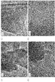
- FIG. 3 to 5 show examples of the results of observation of the carbon structure of the carbon catalyst with a transmission electron microscope.
- the carbon catalyst Fe100 / Cu0 (H) (FIGS. 3A to 3C: 40k, FIG. 3D: 600k)
- FIG. (A) to FIG. 4 (D) show carbon catalysts Fe0 / Cu100 (H) (FIG. 4 (A) to FIG. 4 (C): 40k, FIG. 4 (D): 150k)
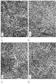
- FIG. 5 (D) shows transmission electron micrographs of the carbon catalyst Fe25 / Cu75 (H) (FIGS. 5 (A) to 5 (C): 40k, FIG. 5 (D): 150k).
- FIGS. 3 (A) to 3 (D) a developed shell-like structure was confirmed in the carbon structure of the carbon catalyst Fe100 / Cu0 (H) obtained using only iron as a metal. .
- the high crystallinity (44.08%) shown in FIG. 2 supported such a carbon structure.
- the N / C ratio was relatively small (0.84).
- the oxygen reduction initiation potential was relatively large (0.764 (V vs. NHE)), but not at a sufficient level.
- the current density was small ( ⁇ 0.045 mA / cm 2 ).
- FIGS. 4A to 4D no shell-like structure was confirmed in the carbon structure of the carbon catalyst Fe0 / Cu100 (H) obtained using only copper as the metal.
- the crystallinity (0.00%) shown in FIG. 2 supports such a carbon structure.
- the N / C ratio was remarkably large (4.90).
- the oxygen reduction starting potential was small (0.692 (V vs. NHE) and the current density was also small ( ⁇ 0.003 mA / cm 2 ).
- FIGS. 5 (A) to 5 (D) in the carbon structure of the carbon catalyst Fe25 / Cu75 (H) obtained by using iron and copper as metals, the above-mentioned carbon catalyst is used.
- a shell-like structure having a smaller size was formed in a smaller proportion than Fe100 / Cu0 (H).
- the relatively low crystallinity (9.82%) shown in FIG. 2 supported such a carbon structure.
- the N / C ratio was relatively large (4.16).
- the oxygen reduction starting potential was remarkably large (0.834 (V vs. NHE) and the current density was also large ( ⁇ 0.281 mA / cm 2 ).
- the carbon catalyst Fe100 / Cu0 (1.25) (H) obtained using NO the latter has a higher crystallinity (36.84%) than the former, and the N / C ratio Was small (1.24), the oxygen reduction initiation potential was small (0.773 (V vs. NHE)), and the current density was also small ( ⁇ 0.097 mA / cm 2 ).
- the carbon catalyst Fe75 / Cu25 (H) obtained using a relatively large amount (3.75 wt%) of iron and a small amount of copper (1.25 wt%) Comparing the carbon catalyst Fe25 / Cu75 (15) (H) obtained using a quantity (3.75 wt%) of iron and a higher quantity of copper (11.25 wt%), the latter is Compared with the former, a decrease in crystallinity, an increase in N / C ratio, and an improvement in oxygen reduction catalytic activity were obtained.
- the high oxygen reduction catalytic activity obtained by combining iron and copper was not achieved simply by introducing nitrogen atoms externally. That is, the carbon catalyst Fe100 / Cu0 (H) (N) was obtained by subjecting the carbon catalyst Fe100 / Cu0 (H) to nitrogen doping treatment and introducing nitrogen atoms externally. Compared with Fe100 / Cu0 (H), although the N / C ratio increased remarkably, the increase in the oxygen reduction initiation potential was not so large.
- carbon catalysts obtained using iron and copper and having an N / C ratio similar to that of the carbon catalyst Fe100 / Cu0 (H) (N) for example, Fe35 / Cu65 (H), Fe25 / Cu75).
- C900) (H), Fe25 / Cu75 (C1000) (H) showed a high oxygen reduction starting potential of 0.810 V (vs. NHE) or more.
- the carbon catalyst Fe23 / Cu63 / Co8 (H) obtained by using other metals also had an effect of a combination of iron and copper.
- the above-mentioned effects by the combined use of iron and copper were not obtained with other transition metals, and were specific to copper. That is, as shown in FIG. 2, the oxygen reduction initiation potential of the carbon catalyst (Fe25 / Ni75, Fe25 / Mn) obtained by combining iron and nickel or using iron and manganese without using copper is Compared with the carbon catalyst Fe100 / Cu0 (1.25) obtained by using only the same amount of iron, it was lowered.
Abstract
Description
まず、炭素化の対象となる原料を調製した。すなわち、アセトン800mLに、フェノール樹脂(PSK-2320、群栄化学工業株式会社製)10gを添加し、超音波洗浄器内における10分間の超音波処理によって、当該フェノール樹脂をアセトンに溶解させた。 [Production of carbon catalyst Fe100 / Cu0]
First, the raw material used as the object of carbonization was prepared. That is, 10 g of phenol resin (PSK-2320, manufactured by Gunei Chemical Industry Co., Ltd.) was added to 800 mL of acetone, and the phenol resin was dissolved in acetone by ultrasonic treatment for 10 minutes in an ultrasonic cleaner.
金属の合計量に対する鉄の含有量の割合を75wt%及び銅の含有量の割合を25wt%としたこと以外は、上述の炭素触媒Fe100/Cu0と同様にして、炭素触媒を製造した。 [Production of carbon catalyst Fe75 / Cu25]
A carbon catalyst was produced in the same manner as the above-described carbon catalyst Fe100 / Cu0 except that the ratio of the iron content to the total amount of metal was 75 wt% and the ratio of the copper content was 25 wt%.
金属の合計量に対する鉄の含有量の割合を50wt%及び銅の含有量の割合を50wt%とした(フタロシアニン鉄2.54g及びフタロシアニン銅2.27gを使用した)こと以外は、上述の炭素触媒Fe75/Cu25と同様にして、炭素触媒Fe50/Cu50を製造した。 [Production of carbon catalyst Fe50 / Cu50]
The above carbon catalyst except that the ratio of the iron content to the total amount of metal was 50 wt% and the ratio of the copper content was 50 wt% (2.54 g of phthalocyanine iron and 2.27 g of phthalocyanine copper were used). A carbon catalyst Fe50 / Cu50 was produced in the same manner as Fe75 / Cu25.
金属の合計量に対する鉄の含有量の割合を35wt%及び銅の含有量の割合を65wt%とした(フタロシアニン鉄1.78g及びフタロシアニン銅2.95gを使用した)こと以外は、上述の炭素触媒Fe75/Cu25と同様にして、炭素触媒Fe35/Cu65を製造した。 [Production of carbon catalyst Fe35 / Cu65]
The above carbon catalyst except that the ratio of iron content to the total amount of metal was 35 wt% and the ratio of copper content was 65 wt% (using 1.78 g of phthalocyanine iron and 2.95 g of phthalocyanine copper). A carbon catalyst Fe35 / Cu65 was produced in the same manner as Fe75 / Cu25.
金属の合計量に対する鉄の含有量の割合を25wt%及び銅の含有量の割合を75wt%とした(フタロシアニン鉄1.27g及びフタロシアニン銅3.40gを使用した)こと以外は、上述の炭素触媒Fe75/Cu25と同様にして、炭素触媒Fe25/Cu75を製造した。 [Production of carbon catalyst Fe25 / Cu75]
The above carbon catalyst except that the ratio of the iron content to the total amount of metal was 25 wt% and the ratio of the copper content was 75 wt% (using 1.27 g of phthalocyanine iron and 3.40 g of phthalocyanine copper). A carbon catalyst Fe25 / Cu75 was produced in the same manner as Fe75 / Cu25.
金属の合計量に対する鉄の含有量の割合を15wt%及び銅の含有量の割合を85wt%とした(フタロシアニン鉄0.76g及びフタロシアニン銅3.85gを使用した)こと以外は、上述の炭素触媒Fe75/Cu25と同様にして、炭素触媒Fe15/Cu85を製造した。 [Production of carbon catalyst Fe15 / Cu85]
The above-mentioned carbon catalyst except that the ratio of iron content to the total amount of metal is 15 wt% and the ratio of copper content is 85 wt% (0.76 g of phthalocyanine iron and 3.85 g of phthalocyanine copper are used) A carbon catalyst Fe15 / Cu85 was produced in the same manner as Fe75 / Cu25.
金属の合計量に対する銅の含有量の割合を100wt%とした(フタロシアニン銅4.53gを使用した)こと以外は、上述の炭素触媒Fe100/Cu0と同様にして、炭素触媒Fe0/Cu100を製造した。 [Production of carbon catalyst Fe0 / Cu100]
A carbon catalyst Fe0 / Cu100 was produced in the same manner as the above-described carbon catalyst Fe100 / Cu0 except that the ratio of the copper content to the total amount of metal was 100 wt% (4.53 g of phthalocyanine copper was used). .
炭素化温度を900℃としたこと以外は、上述の炭素触媒Fe25/Cu75と同様にして、炭素触媒Fe25/Cu75(C900)を製造した。 [Production of carbon catalyst Fe25 / Cu75 (C900)]
A carbon catalyst Fe25 / Cu75 (C900) was produced in the same manner as the carbon catalyst Fe25 / Cu75 described above except that the carbonization temperature was 900 ° C.
炭素化温度を1000℃としたこと以外は、上述の炭素触媒Fe25/Cu75と同様にして、炭素触媒Fe25/Cu75(C900)を製造した。 [Production of carbon catalyst Fe25 / Cu75 (C1000)]
A carbon catalyst Fe25 / Cu75 (C900) was produced in the same manner as the carbon catalyst Fe25 / Cu75 described above except that the carbonization temperature was 1000 ° C.
金属の合計量を10wt%とした(フタロシアニン鉄2.54g及びフタロシアニン銅6.80gを使用した)こと以外は、上述の炭素触媒Fe25/Cu75と同様にして、炭素触媒Fe25/Cu75(10)を製造した。 [Production of carbon catalyst Fe25 / Cu75 (10)]
A carbon catalyst Fe25 / Cu75 (10) was prepared in the same manner as the carbon catalyst Fe25 / Cu75 described above except that the total amount of metal was 10 wt% (2.54 g of phthalocyanine iron and 6.80 g of phthalocyanine copper were used). Manufactured.
金属の合計量を15wt%とした(フタロシアニン鉄3.82g及びフタロシアニン銅10.20gを使用した)こと以外は、上述の炭素触媒Fe25/Cu75と同様にして、炭素触媒Fe25/Cu75(15)を製造した。 [Production of carbon catalyst Fe25 / Cu75 (15)]
The carbon catalyst Fe25 / Cu75 (15) was prepared in the same manner as the carbon catalyst Fe25 / Cu75 described above except that the total amount of metal was 15 wt% (3.82 g of phthalocyanine iron and 10.20 g of phthalocyanine copper were used). Manufactured.
金属の合計量に対する鉄の含有量の割合を23.08wt%、銅の含有量の割合を69.23wt%及びコバルトの含有量の割合を7.69wt%とした(フタロシアニン鉄1.17g、フタロシアニン銅3.14g及びフタロシアニンコバルト0.37gを使用した)こと以外は、上述の炭素触媒Fe25/Cu75と同様にして、炭素触媒Fe23/Cu69/Co8を製造した。 [Production of carbon catalyst Fe23 / Cu69 / Co8]
The ratio of the iron content to the total metal content was 23.08 wt%, the copper content ratio was 69.23 wt%, and the cobalt content ratio was 7.69 wt% (phthalocyanine iron 1.17 g, phthalocyanine A carbon catalyst Fe23 / Cu69 / Co8 was produced in the same manner as the carbon catalyst Fe25 / Cu75 described above except that 3.14 g of copper and 0.37 g of phthalocyanine cobalt were used.
金属の合計量に対する鉄の含有量の割合を75wt%及びニッケルの含有量の割合を25wt%とした(フタロシアニン鉄3.82g及びフタロシアニンニッケル1.21gを使用した)こと以外は、上述の炭素触媒Fe75/Cu25と同様にして、炭素触媒Fe75/Ni25を製造した。 [Production of carbon catalyst Fe75 / Ni25]
The above carbon catalyst except that the ratio of the iron content to the total amount of metal was 75 wt% and the ratio of the nickel content was 25 wt% (3.82 g of phthalocyanine iron and 1.21 g of phthalocyanine nickel were used). A carbon catalyst Fe75 / Ni25 was produced in the same manner as Fe75 / Cu25.
金属の合計量に対する鉄の含有量の割合を25wt%及びニッケルの含有量の割合を75wt%とした(フタロシアニン鉄1.27g及びフタロシアニンニッケル3.65gを使用した)こと以外は、上述の炭素触媒Fe75/Cu25と同様にして、炭素触媒Fe25/Ni75を製造した。 [Production of carbon catalyst Fe25 / Ni75]
The above carbon catalyst except that the ratio of the iron content to the total amount of metal was 25 wt% and the ratio of the nickel content was 75 wt% (1.27 g of phthalocyanine iron and 3.65 g of phthalocyanine nickel were used). A carbon catalyst Fe25 / Ni75 was produced in the same manner as Fe75 / Cu25.
金属の合計量に対するニッケルの含有量の割合を100wt%とした(フタロシアニンニッケル4.87gを使用した)こと以外は、上述の炭素触媒Fe0/Cu100と同様にして、炭素触媒Fe0/Ni100を製造した。 [Production of carbon catalyst Fe0 / Ni100]
A carbon catalyst Fe0 / Ni100 was produced in the same manner as the above-described carbon catalyst Fe0 / Cu100, except that the ratio of nickel content to the total amount of metal was 100 wt% (4.87 g of phthalocyanine nickel was used). .
金属の合計量に対する鉄の含有量の割合を75wt%及びマンガンの含有量の割合を25wt%とした(フタロシアニン鉄3.82g及びフタロシアニンマンガン1.29gを使用した)こと以外は、上述の炭素触媒Fe75/Cu25と同様にして、炭素触媒Fe75/Mn25を製造した。 [Production of carbon catalyst Fe75 / Mn25]
The above carbon catalyst except that the ratio of iron content to the total amount of metal was 75 wt% and the ratio of manganese content was 25 wt% (3.82 g of phthalocyanine iron and 1.29 g of phthalocyanine manganese were used). A carbon catalyst Fe75 / Mn25 was produced in the same manner as Fe75 / Cu25.
金属の合計量に対する鉄の含有量の割合を25wt%及びマンガンの含有量の割合を75wt%とした(フタロシアニン鉄1.27g及びフタロシアニンマンガン3.87gを使用した)こと以外は、上述の炭素触媒Fe75/Cu25と同様にして、炭素触媒Fe25/Mn75を製造した。 [Production of carbon catalyst Fe25 / Mn75]
The above-mentioned carbon catalyst except that the ratio of iron content to the total amount of metal is 25 wt% and the ratio of manganese content is 75 wt% (1.27 g of phthalocyanine iron and 3.87 g of phthalocyanine manganese are used) A carbon catalyst Fe25 / Mn75 was produced in the same manner as Fe75 / Cu25.
金属の合計量に対するマンガンの含有量の割合を100wt%とした(フタロシアニンマンガン5.16gを使用した)こと以外は、上述の炭素触媒Fe0/Cu100と同様にして、炭素触媒Fe0/Mn100を製造した。 [Production of carbon catalyst Fe0 / Mn100]
A carbon catalyst Fe0 / Mn100 was produced in the same manner as the above-described carbon catalyst Fe0 / Cu100 except that the ratio of manganese content to the total amount of metal was 100 wt% (5.16 g of phthalocyanine manganese was used). .
上述のようにして得られた炭素触媒Fe100/Cu0に熱処理を施した。すなわち、炭素触媒Fe100/Cu0を赤外線イメージ炉内、窒素雰囲気下で、昇温速度50℃/分にて加熱した。そして、炭素触媒Fe100/Cu0を700℃で1時間保持することにより熱処理を行った。こうして、熱処理が施された炭素触媒Fe100/Cu0を、炭素触媒Fe100/Cu0(H)として得た。 [Production of carbon catalyst Fe100 / Cu0 (H)]
The carbon catalyst Fe100 / Cu0 obtained as described above was subjected to heat treatment. That is, the carbon catalyst Fe100 / Cu0 was heated in an infrared image furnace in a nitrogen atmosphere at a heating rate of 50 ° C./min. And it heat-processed by hold | maintaining carbon catalyst Fe100 / Cu0 at 700 degreeC for 1 hour. Thus, the carbon catalyst Fe100 / Cu0 subjected to the heat treatment was obtained as the carbon catalyst Fe100 / Cu0 (H).
上述のようにして得られた炭素触媒Fe75/Cu25に熱処理を施したこと以外は、上述の炭素触媒Fe100/Cu0(H)と同様にして、炭素触媒Fe75/Cu25(H)を製造した。 [Production of carbon catalyst Fe75 / Cu25 (H)]
A carbon catalyst Fe75 / Cu25 (H) was produced in the same manner as the carbon catalyst Fe100 / Cu0 (H) except that the carbon catalyst Fe75 / Cu25 obtained as described above was heat-treated.
上述のようにして得られた炭素触媒Fe50/Cu50に熱処理を施したこと以外は、上述の炭素触媒Fe100/Cu0(H)と同様にして、炭素触媒Fe50/Cu50(H)を製造した。 [Production of carbon catalyst Fe50 / Cu50 (H)]
A carbon catalyst Fe50 / Cu50 (H) was produced in the same manner as the carbon catalyst Fe100 / Cu0 (H) except that the carbon catalyst Fe50 / Cu50 obtained as described above was heat-treated.
上述のようにして得られた炭素触媒Fe35/Cu65に熱処理を施したこと以外は、上述の炭素触媒Fe100/Cu0(H)と同様にして、炭素触媒Fe35/Cu65(H)を製造した。 [Production of carbon catalyst Fe35 / Cu65 (H)]
A carbon catalyst Fe35 / Cu65 (H) was produced in the same manner as the carbon catalyst Fe100 / Cu0 (H) except that the carbon catalyst Fe35 / Cu65 obtained as described above was heat-treated.
上述のようにして得られた炭素触媒Fe25/Cu75に熱処理を施したこと以外は、上述の炭素触媒Fe100/Cu0(H)と同様にして、炭素触媒Fe25/Cu75(H)を製造した。 [Production of carbon catalyst Fe25 / Cu75 (H)]
A carbon catalyst Fe25 / Cu75 (H) was produced in the same manner as the carbon catalyst Fe100 / Cu0 (H) except that the carbon catalyst Fe25 / Cu75 obtained as described above was heat-treated.
上述のようにして得られた炭素触媒Fe15/Cu85に熱処理を施したこと以外は、上述の炭素触媒Fe100/Cu0(H)と同様にして、炭素触媒Fe15/Cu85(H)を製造した。 [Production of carbon catalyst Fe15 / Cu85 (H)]
A carbon catalyst Fe15 / Cu85 (H) was produced in the same manner as the carbon catalyst Fe100 / Cu0 (H) except that the carbon catalyst Fe15 / Cu85 obtained as described above was heat-treated.
上述のようにして得られた炭素触媒Fe0/Cu100に熱処理を施したこと以外は、上述の炭素触媒Fe100/Cu0(H)と同様にして、炭素触媒Fe0/Cu100(H)を製造した。 [Production of carbon catalyst Fe0 / Cu100 (H)]
A carbon catalyst Fe0 / Cu100 (H) was produced in the same manner as the carbon catalyst Fe100 / Cu0 (H) except that the carbon catalyst Fe0 / Cu100 obtained as described above was heat-treated.
上述のようにして得られた炭素触媒Fe25/Cu75(C900)に熱処理を施したこと以外は、上述の炭素触媒Fe100/Cu0(H)と同様にして、炭素触媒Fe25/Cu75(C900)(H)を製造した。 [Production of carbon catalyst Fe25 / Cu75 (C900) (H)]
The carbon catalyst Fe25 / Cu75 (C900) (H) was obtained in the same manner as the carbon catalyst Fe100 / Cu0 (H) except that the carbon catalyst Fe25 / Cu75 (C900) obtained as described above was heat-treated. ) Was manufactured.
上述のようにして得られた炭素触媒Fe25/Cu75(C1000)に熱処理を施したこと以外は、上述の炭素触媒Fe100/Cu0(H)と同様にして、炭素触媒Fe25/Cu75(C1000)(H)を製造した。 [Production of carbon catalyst Fe25 / Cu75 (C1000) (H)]
The carbon catalyst Fe25 / Cu75 (C1000) (H) was prepared in the same manner as the carbon catalyst Fe100 / Cu0 (H) except that the carbon catalyst Fe25 / Cu75 (C1000) obtained as described above was heat-treated. ) Was manufactured.
上述のようにして得られた炭素触媒Fe25/Cu75(10)に熱処理を施したこと以外は、上述の炭素触媒Fe100/Cu0(H)と同様にして、炭素触媒Fe25/Cu75(10)(H)を製造した。 [Production of carbon catalyst Fe25 / Cu75 (10) (H)]
The carbon catalyst Fe25 / Cu75 (10) (H) was obtained in the same manner as the carbon catalyst Fe100 / Cu0 (H) except that the carbon catalyst Fe25 / Cu75 (10) obtained as described above was heat-treated. ) Was manufactured.
上述のようにして得られた炭素触媒Fe25/Cu75(15)に熱処理を施したこと以外は、上述の炭素触媒Fe100/Cu0(H)と同様にして、炭素触媒Fe25/Cu75(15)(H)を製造した。 [Production of carbon catalyst Fe25 / Cu75 (15) (H)]
The carbon catalyst Fe25 / Cu75 (15) (H) was prepared in the same manner as the carbon catalyst Fe100 / Cu0 (H) except that the carbon catalyst Fe25 / Cu75 (15) obtained as described above was heat-treated. ) Was manufactured.
まず、金属の合計量を1.25wt%とし、且つ当該金属の合計量に対する鉄の含有量の割合を100wt%とした(フタロシアニン鉄1.27gを使用した)こと以外は、上述の炭素触媒Fe100/Cu0と同様にして、炭素触媒Fe100/Cu0(1.25)を製造した。 [Production of carbon catalyst Fe100 / Cu0 (1.25) (H)]
First, the carbon catalyst Fe100 described above, except that the total amount of metal was 1.25 wt% and the ratio of the iron content to the total amount of the metal was 100 wt% (1.27 g of phthalocyanine iron was used). The carbon catalyst Fe100 / Cu0 (1.25) was produced in the same manner as / Cu0.
上述のようにして得られた炭素触媒Fe23/Cu69/Co8に熱処理を施したこと以外は、上述の炭素触媒Fe100/Cu0(H)と同様にして、炭素触媒Fe23/Cu69/Co8(H)を製造した。 [Production of carbon catalyst Fe23 / Cu69 / Co8 (H)]
The carbon catalyst Fe23 / Cu69 / Co8 (H) was treated in the same manner as the carbon catalyst Fe100 / Cu0 (H) except that the carbon catalyst Fe23 / Cu69 / Co8 obtained as described above was heat-treated. Manufactured.
上述のようにして得られた炭素触媒Fe100/Cu0(H)に窒素ドープ処理を施した。すなわち、炭素触媒Fe100/Cu0(H)を、アンモニアガスと空気との混合ガス(アンモニアガス:空気=7:3(体積比))中、600℃で2時間保持することにより、当該炭素触媒Fe100/Cu0(H)に窒素原子をドープした。こうして、窒素ドープ処理が施された炭素触媒Fe100/Cu0(H)を、炭素触媒Fe100/Cu0(H)(N)として得た。 [Production of carbon catalyst Fe100 / Cu0 (H) (N)]
The carbon catalyst Fe100 / Cu0 (H) obtained as described above was subjected to nitrogen doping treatment. That is, the carbon catalyst Fe100 / Cu0 (H) is held in a mixed gas of ammonia gas and air (ammonia gas: air = 7: 3 (volume ratio)) at 600 ° C. for 2 hours, thereby the carbon catalyst Fe100. / NiO was doped into Cu0 (H). Thus, the carbon catalyst Fe100 / Cu0 (H) subjected to the nitrogen doping treatment was obtained as the carbon catalyst Fe100 / Cu0 (H) (N).
上述のようにして得られた炭素触媒Fe75/Cu25(H)に窒素ドープ処理を施したこと以外は、上述の炭素触媒Fe100/Cu0(H)(N)と同様にして、炭素触媒Fe75/Cu25(H)(N)を製造した。 [Production of carbon catalyst Fe75 / Cu25 (H) (N)]
The carbon catalyst Fe75 / Cu25 (N) was obtained in the same manner as the carbon catalyst Fe100 / Cu0 (H) (N) except that the carbon catalyst Fe75 / Cu25 (H) obtained as described above was subjected to nitrogen doping treatment. (H) (N) was produced.
まず、金属の合計量に対するコバルトの含有量の割合を100wt%とした(フタロシアニンコバルト4.85gを使用した)こと以外は、上述の炭素触媒Fe100/Cu0と同様にして、炭素触媒Co100/Cu0を製造した。 [Production of carbon catalyst Co100 / Cu0 (H)]
First, the carbon catalyst Co100 / Cu0 was changed in the same manner as the above-described carbon catalyst Fe100 / Cu0 except that the ratio of the cobalt content to the total amount of metal was 100 wt% (4.85 g of phthalocyanine cobalt was used). Manufactured.
金属の合計量に対するコバルトの含有量の割合を75wt%及び銅の含有量の割合を25wt%とした(フタロシアニンコバルト3.64g及びフタロシアニン銅1.13gを使用した)こと以外は、上述の炭素触媒Fe100/Cu0(H)と同様にして、炭素触媒Co75/Cu25(H)を製造した。 [Production of carbon catalyst Co75 / Cu25 (H)]
The above carbon catalyst except that the ratio of cobalt content to the total amount of metal was 75 wt% and the ratio of copper content was 25 wt% (3.64 g of phthalocyanine cobalt and 1.13 g of phthalocyanine copper were used). A carbon catalyst Co75 / Cu25 (H) was produced in the same manner as Fe100 / Cu0 (H).
金属の合計量に対するコバルトの含有量の割合を25wt%及び銅の含有量の割合を75wt%とした(フタロシアニンコバルト1.21g及びフタロシアニン銅3.40gを使用した)こと以外は、上述の炭素触媒Fe100/Cu0(H)と同様にして、炭素触媒Co25/Cu75(H)を製造した。 [Production of carbon catalyst Co25 / Cu75 (H)]
The above-mentioned carbon catalyst except that the proportion of cobalt content to the total amount of metal was 25 wt% and the proportion of copper content was 75 wt% (1.21 g of phthalocyanine cobalt and 3.40 g of phthalocyanine copper were used). A carbon catalyst Co25 / Cu75 (H) was produced in the same manner as Fe100 / Cu0 (H).
上述のようにして得られた炭素触媒Fe25/Ni75に熱処理を施したこと以外は、上述の炭素触媒Fe100/Cu0(H)と同様にして、炭素触媒Fe25/Ni75(H)を製造した。 [Production of carbon catalyst Fe25 / Ni75 (H)]
A carbon catalyst Fe25 / Ni75 (H) was produced in the same manner as the carbon catalyst Fe100 / Cu0 (H) except that the carbon catalyst Fe25 / Ni75 obtained as described above was heat-treated.
上述のようにして得られた炭素触媒Fe0/Ni100に熱処理を施したこと以外は、上述の炭素触媒Fe100/Cu0(H)と同様にして、炭素触媒Fe0/Ni100(H)を製造した。 [Production of carbon catalyst Fe0 / Ni100 (H)]
A carbon catalyst Fe0 / Ni100 (H) was produced in the same manner as the carbon catalyst Fe100 / Cu0 (H) except that the carbon catalyst Fe0 / Ni100 obtained as described above was heat-treated.
上述のようにして得られた炭素触媒Fe25/Mn75に熱処理を施したこと以外は、上述の炭素触媒Fe100/Cu0(H)と同様にして、炭素触媒Fe25/Mn75(H)を製造した。 [Production of carbon catalyst Fe25 / Mn75 (H)]
A carbon catalyst Fe25 / Mn75 (H) was produced in the same manner as the carbon catalyst Fe100 / Cu0 (H) except that the carbon catalyst Fe25 / Mn75 obtained as described above was subjected to heat treatment.
上述のようにして得られた炭素触媒Fe0/Mn100に熱処理を施したこと以外は、上述の炭素触媒Fe100/Cu0(H)と同様にして、炭素触媒Fe0/Mn100(H)を製造した。 [Production of carbon catalyst Fe0 / Mn100 (H)]
A carbon catalyst Fe0 / Mn100 (H) was produced in the same manner as the carbon catalyst Fe100 / Cu0 (H) except that the carbon catalyst Fe0 / Mn100 obtained as described above was heat-treated.
上述のようにして得られた炭素触媒を透過型顕微鏡(TEM)にて観察した。 [Transmission electron microscope observation]
The carbon catalyst obtained as described above was observed with a transmission microscope (TEM).
粉末状の炭素触媒の試料を、ガラス試料板の凹部(2cm×2cm×厚さ0.2mm)に入れるとともにスライドガラスで押さえ、当該試料をその表面と基準面とが一致するように当該凹部に均一に充填した。次いで、この充填された試料の形態が崩れないように、ガラス試料板を広角X線回折試料台に固定した。 [Evaluation of crystallinity]
A powdery carbon catalyst sample is put into a recess (2 cm × 2 cm × thickness 0.2 mm) of a glass sample plate and pressed with a slide glass, and the sample is placed in the recess so that the surface and the reference surface coincide with each other. Filled uniformly. Next, the glass sample plate was fixed to a wide-angle X-ray diffraction sample stage so that the shape of the filled sample did not collapse.
X線光電子分光装置(AXIS NOVA、KRATOS社製)を用いたXPS法により、炭素触媒の表面における炭素原子及び窒素原子の内殻準位からの光電子スペクトルを測定した。X線源にはAlKα線(10mA、15kV、Pass energy 40eV)を用いた。 [N / C ratio evaluation]
A photoelectron spectrum from the core level of carbon atoms and nitrogen atoms on the surface of the carbon catalyst was measured by an XPS method using an X-ray photoelectron spectrometer (AXIS NOVA, manufactured by KRATOS). AlKα rays (10 mA, 15 kV, Pass energy 40 eV) were used as the X-ray source.
まず、触媒スラリーを調製した。すなわち、粉末状の炭素触媒を5mg量り取り、これに50μLのバインダー溶液(ナフィオン(商標登録)、デュポン株式会社)、150μLの水、150μLのエタノール、スパチュラで2杯(約15粒)のガラスビーズ(直径1mm)を混合し、10分間超音波処理することにより、触媒が均一に分散された触媒スラリーを調製した。 [Evaluation of oxygen reduction catalytic activity]
First, a catalyst slurry was prepared. That is, 5 mg of powdered carbon catalyst was weighed, and 50 μL of binder solution (Nafion (registered trademark), DuPont), 150 μL of water, 150 μL of ethanol, and 2 cups (about 15 grains) of glass beads with spatula. (Diameter 1 mm) was mixed and subjected to ultrasonic treatment for 10 minutes to prepare a catalyst slurry in which the catalyst was uniformly dispersed.
Claims (9)
- 窒素原子を含む有機物と金属とを含む原料を炭素化して得られる炭素触媒であって、
前記金属として、鉄及び/又はコバルトと、銅と、を含む
ことを特徴とする炭素触媒。 A carbon catalyst obtained by carbonizing a raw material containing an organic substance containing a nitrogen atom and a metal,
A carbon catalyst comprising iron and / or cobalt and copper as the metal. - 鉄の含有量及び/又はコバルトの含有量と銅の含有量との合計に対する銅の含有量の割合が10~95質量%である
ことを特徴とする請求項1に記載された炭素触媒。 The carbon catalyst according to claim 1, wherein the ratio of the copper content to the total of the iron content and / or the cobalt content and the copper content is 10 to 95% by mass. - 前記金属として、少なくとも鉄及び銅を含む
ことを特徴とする請求項1又は2に記載された炭素触媒。 The carbon catalyst according to claim 1 or 2, wherein the metal includes at least iron and copper. - X線回折法により得られる結晶化度が41.0%以下であり、
X線光電子分光により得られる窒素原子/炭素原子比が0.7以上であり、
酸素還元開始電位が0.774V(vs.NHE)以上である
ことを特徴とする炭素触媒。 The crystallinity obtained by X-ray diffraction method is 41.0% or less,
The nitrogen atom / carbon atom ratio obtained by X-ray photoelectron spectroscopy is 0.7 or more,
The carbon catalyst characterized by having an oxygen reduction starting potential of 0.774 V (vs. NHE) or more. - 請求項1乃至4のいずれかに記載された炭素触媒を含む
ことを特徴とする電極。 An electrode comprising the carbon catalyst according to any one of claims 1 to 4. - 請求項5に記載された電極を備えた
ことを特徴とする電池。 A battery comprising the electrode according to claim 5. - 窒素原子を含む有機物と金属とを含む原料を炭素化して炭素触媒を製造する方法であって、
前記金属は、鉄及び/又はコバルトと、銅と、を含む
ことを特徴とする炭素触媒の製造方法。 A method for producing a carbon catalyst by carbonizing a raw material containing an organic substance containing a nitrogen atom and a metal,
The said metal contains iron and / or cobalt, and copper. The manufacturing method of the carbon catalyst characterized by the above-mentioned. - 前記原料における鉄の含有量及び/又はコバルトの含有量と銅の含有量との合計に対する銅の含有量の割合が10~95質量%である
ことを特徴とする請求項7に記載された炭素触媒の製造方法。 The carbon according to claim 7, wherein the ratio of the copper content to the total of the iron content and / or the cobalt content and the copper content in the raw material is 10 to 95% by mass. A method for producing a catalyst. - 前記金属は、少なくとも鉄及び銅を含む
ことを特徴とする請求項7又は8に記載された炭素触媒の製造方法。 The method for producing a carbon catalyst according to claim 7 or 8, wherein the metal contains at least iron and copper.
Priority Applications (5)
| Application Number | Priority Date | Filing Date | Title |
|---|---|---|---|
| CA2817237A CA2817237C (en) | 2010-11-08 | 2011-11-01 | Carbon catalyst and process for production thereof, and electrode and battery each equipped with same |
| CN201180053814.6A CN103221129B (en) | 2010-11-08 | 2011-11-01 | Carbon catalyst and process for production thereof, and electrode and battery each equipped with same |
| KR1020137011106A KR101367602B1 (en) | 2010-11-08 | 2011-11-01 | Carbon catalyst and process for production thereof, and electrode and battery each equipped with same |
| EP11839356.0A EP2638963B1 (en) | 2010-11-08 | 2011-11-01 | Carbon catalyst and process for production thereof, and electrode and battery each equipped with same |
| US13/881,456 US8999874B2 (en) | 2010-11-08 | 2011-11-01 | Carbon catalyst and process for production thereof, and electrode and battery each equipped with same |
Applications Claiming Priority (2)
| Application Number | Priority Date | Filing Date | Title |
|---|---|---|---|
| JP2010-250270 | 2010-11-08 | ||
| JP2010250270A JP5149364B2 (en) | 2010-11-08 | 2010-11-08 | Carbon catalyst, method for producing the same, electrode and battery using the same |
Publications (1)
| Publication Number | Publication Date |
|---|---|
| WO2012063681A1 true WO2012063681A1 (en) | 2012-05-18 |
Family
ID=46050831
Family Applications (1)
| Application Number | Title | Priority Date | Filing Date |
|---|---|---|---|
| PCT/JP2011/075187 WO2012063681A1 (en) | 2010-11-08 | 2011-11-01 | Carbon catalyst and process for production thereof, and electrode and battery each equipped with same |
Country Status (7)
| Country | Link |
|---|---|
| US (1) | US8999874B2 (en) |
| EP (1) | EP2638963B1 (en) |
| JP (1) | JP5149364B2 (en) |
| KR (1) | KR101367602B1 (en) |
| CN (1) | CN103221129B (en) |
| CA (1) | CA2817237C (en) |
| WO (1) | WO2012063681A1 (en) |
Cited By (5)
| Publication number | Priority date | Publication date | Assignee | Title |
|---|---|---|---|---|
| WO2014199880A1 (en) * | 2013-06-14 | 2014-12-18 | 日清紡ホールディングス株式会社 | Porous carbon catalyst, method for producing same, electrode and battery |
| EP2871154A4 (en) * | 2012-07-06 | 2015-12-23 | Panasonic Ip Man Co Ltd | Carbon-based material, electrode catalyst, electrode, gas diffusion electrode, electrochemical device, fuel battery, and process for producing carbon-based material |
| US20160064154A1 (en) * | 2011-08-31 | 2016-03-03 | Semiconductor Energy Laboratory Co., Ltd. | Negative electrode of power storage device and power storage device |
| CN114597427A (en) * | 2022-03-10 | 2022-06-07 | 合肥工业大学智能制造技术研究院 | Preparation method and application of nitrogen-doped carbon-coated cobaltosic oxide @ cobalt non-noble metal oxygen reduction catalyst |
| CN116060074A (en) * | 2021-11-01 | 2023-05-05 | 中自环保科技股份有限公司 | Catalytic carrier for electrochemical reaction and preparation method thereof |
Families Citing this family (27)
| Publication number | Priority date | Publication date | Assignee | Title |
|---|---|---|---|---|
| JP5660917B2 (en) * | 2011-02-04 | 2015-01-28 | 国立大学法人東京工業大学 | Air electrode catalyst for fuel cell and production method thereof |
| US20150214554A1 (en) * | 2012-08-01 | 2015-07-30 | Toyo Ink Sc Holdings Co., Ltd. | Cell catalyst composition andmanufacturing method thereof, electrode material, and fuel cell |
| JP6257910B2 (en) * | 2013-04-02 | 2018-01-10 | 旭化成株式会社 | Nitrogen-containing carbon material, method for producing the same, and electrode for fuel cell |
| KR20140143045A (en) * | 2013-06-05 | 2014-12-15 | 삼성정밀화학 주식회사 | Biodegradable polyester resin and article including the same |
| CN103496694B (en) * | 2013-09-27 | 2015-08-26 | 安徽理工大学 | Composite catalyst affects the catalyzed graphitization of resin material |
| WO2015080274A1 (en) * | 2013-11-29 | 2015-06-04 | 国立大学法人群馬大学 | Method for manufacturing carbon catalyst, and carbon catalyst |
| CN104269566B (en) * | 2014-09-22 | 2016-11-30 | 南开大学 | A kind of preparation method and application of N doping porous carbon nanosheet composite material |
| WO2016057666A1 (en) | 2014-10-08 | 2016-04-14 | Energizer Brands, Llc | Fluorosurfactant as a zinc corrosion inhibitor |
| US10205206B2 (en) | 2014-10-08 | 2019-02-12 | Energizer Brands, Llc | Zinc-air electrochemical cell |
| US10319991B2 (en) | 2014-10-23 | 2019-06-11 | Energizer Brands, Llc | Zinc anode composition |
| JP2017091736A (en) * | 2015-11-06 | 2017-05-25 | 旭化成株式会社 | Laminate and method for producing the same, membrane-electrode assembly for fuel cell, polymer electrolyte fuel cell, and direct methanol fuel cell |
| JP6800608B2 (en) * | 2016-05-17 | 2020-12-16 | 日清紡ホールディングス株式会社 | Battery electrode, composition for battery electrode catalyst layer and battery |
| KR102317059B1 (en) * | 2016-06-02 | 2021-10-25 | 닛신보 홀딩스 가부시키 가이샤 | Carbon Catalysts, Cell Electrodes and Cells |
| US10193145B2 (en) * | 2016-06-30 | 2019-01-29 | Hydro-Quebec | Carbon-coated active particles and processes for their preparation |
| JP6857878B2 (en) * | 2016-12-06 | 2021-04-14 | 日清紡ホールディングス株式会社 | Carbon catalyst and electrodes and batteries containing it |
| KR20200029521A (en) * | 2017-07-13 | 2020-03-18 | 닛신보 홀딩스 가부시키 가이샤 | Carbon catalyst, battery electrode and battery |
| CN107742731B (en) * | 2017-09-30 | 2019-12-03 | 湖南工业大学 | A kind of cupric oxygen reduction catalyst and its preparation method and application |
| US11387465B2 (en) | 2017-11-16 | 2022-07-12 | Nisshinbo Holdings Inc. | Cathode, membrane electrode assembly, and battery |
| CN109806765B (en) * | 2019-03-26 | 2021-12-07 | 中国建筑材料科学研究总院有限公司 | Air purification composite material and preparation method thereof |
| CN111755705A (en) * | 2019-03-29 | 2020-10-09 | 浙江晨阳新材料有限公司 | Three-atom-level dispersed metal cluster loaded nitrogen-doped nano carbon fuel cell catalyst |
| JP6630457B2 (en) * | 2019-04-15 | 2020-01-15 | 日清紡ホールディングス株式会社 | Cathode, membrane electrode assembly and battery |
| CN110429290A (en) * | 2019-08-06 | 2019-11-08 | 四川轻化工大学 | A method of preparing nitrogen-doped carbon material load transition metal compound catalyst |
| CN112186175A (en) * | 2020-03-12 | 2021-01-05 | 南京大学 | Oxygen anion battery positive electrode material based on non-noble metal/carbon composite catalytic material and preparation method and application thereof |
| CN112023945B (en) * | 2020-09-01 | 2022-07-05 | 广州大学 | Preparation method of mesoporous carbon-based electrocatalyst |
| CN114573824B (en) * | 2021-03-18 | 2023-07-07 | 天津科技大学 | Preparation of conductive cobalt coordination linear polymer and application of conductive cobalt coordination linear polymer in electrocatalytic oxygen reduction process |
| CN114373969B (en) * | 2022-01-10 | 2023-10-31 | 中国石油大学(北京) | Composite nanofiber modified proton exchange membrane and preparation method and application thereof |
| CN114657593B (en) * | 2022-03-24 | 2023-05-12 | 同济大学 | Preparation method and application of single-atom iron photoelectrode taking carbon base as substrate |
Citations (6)
| Publication number | Priority date | Publication date | Assignee | Title |
|---|---|---|---|---|
| JP2003249231A (en) | 2002-02-26 | 2003-09-05 | Junichi Ozaki | Electrode catalyst for fuel cell and fuel cell using the same |
| JP2005063677A (en) | 2003-08-11 | 2005-03-10 | Nitto Denko Corp | Fuel cell |
| JP2007207662A (en) | 2006-02-03 | 2007-08-16 | Gunma Univ | Electrode catalyst for fuel cell, its manufacturing method, and fuel cell using the catalyst |
| JP2008282725A (en) * | 2007-05-11 | 2008-11-20 | Gunma Univ | Manufacturing method of carbon base electrode catalyst for fuel cell |
| JP2009291706A (en) * | 2008-06-04 | 2009-12-17 | Seizo Miyata | Carbon catalyst, method for manufacturing the same, fuel cell, electric storage apparatus and method for using the catalyst |
| JP2010204116A (en) * | 2004-06-16 | 2010-09-16 | Aisin Aw Co Ltd | Information providing system and program |
Family Cites Families (8)
| Publication number | Priority date | Publication date | Assignee | Title |
|---|---|---|---|---|
| NL76387C (en) * | 1949-03-24 | |||
| US4011374A (en) | 1975-12-02 | 1977-03-08 | The United States Of America As Represented By The United States Energy Research And Development Administration | Porous carbonaceous electrode structure and method for secondary electrochemical cell |
| DE3119707A1 (en) | 1981-05-18 | 1982-12-02 | Kraftwerk Union AG, 4330 Mülheim | Activated-carbon catalyst, especially for decomposing hydrazine |
| US7150920B2 (en) * | 1998-02-24 | 2006-12-19 | Cabot Corporation | Metal-carbon composite powders |
| CN1729052A (en) | 2001-10-18 | 2006-02-01 | 孟山都技术公司 | Process and catalyst for dehydrogenating primary alcohols to make carboxylic acid salts |
| US7550611B2 (en) | 2002-11-14 | 2009-06-23 | Catalytic Materials, Llc | Carbon nanochips as catalyst supports for metals and metal oxides |
| BRPI0708081A2 (en) | 2006-02-17 | 2011-05-17 | Monsanto Technology Llc | transition metal containing catalysts and processes for their preparation and use as thermoelectric stack catalysts |
| JP5540294B2 (en) * | 2009-02-03 | 2014-07-02 | 国立大学法人東京農工大学 | Method for producing electrode catalyst for fuel cell |
-
2010
- 2010-11-08 JP JP2010250270A patent/JP5149364B2/en active Active
-
2011
- 2011-11-01 US US13/881,456 patent/US8999874B2/en active Active
- 2011-11-01 WO PCT/JP2011/075187 patent/WO2012063681A1/en active Application Filing
- 2011-11-01 KR KR1020137011106A patent/KR101367602B1/en active IP Right Grant
- 2011-11-01 CN CN201180053814.6A patent/CN103221129B/en active Active
- 2011-11-01 CA CA2817237A patent/CA2817237C/en active Active
- 2011-11-01 EP EP11839356.0A patent/EP2638963B1/en active Active
Patent Citations (6)
| Publication number | Priority date | Publication date | Assignee | Title |
|---|---|---|---|---|
| JP2003249231A (en) | 2002-02-26 | 2003-09-05 | Junichi Ozaki | Electrode catalyst for fuel cell and fuel cell using the same |
| JP2005063677A (en) | 2003-08-11 | 2005-03-10 | Nitto Denko Corp | Fuel cell |
| JP2010204116A (en) * | 2004-06-16 | 2010-09-16 | Aisin Aw Co Ltd | Information providing system and program |
| JP2007207662A (en) | 2006-02-03 | 2007-08-16 | Gunma Univ | Electrode catalyst for fuel cell, its manufacturing method, and fuel cell using the catalyst |
| JP2008282725A (en) * | 2007-05-11 | 2008-11-20 | Gunma Univ | Manufacturing method of carbon base electrode catalyst for fuel cell |
| JP2009291706A (en) * | 2008-06-04 | 2009-12-17 | Seizo Miyata | Carbon catalyst, method for manufacturing the same, fuel cell, electric storage apparatus and method for using the catalyst |
Non-Patent Citations (1)
| Title |
|---|
| See also references of EP2638963A4 * |
Cited By (9)
| Publication number | Priority date | Publication date | Assignee | Title |
|---|---|---|---|---|
| US20160064154A1 (en) * | 2011-08-31 | 2016-03-03 | Semiconductor Energy Laboratory Co., Ltd. | Negative electrode of power storage device and power storage device |
| US10614967B2 (en) * | 2011-08-31 | 2020-04-07 | Semiconductor Energy Laboratory Co., Ltd. | Negative electrode of power storage device and power storage device |
| US10998141B2 (en) | 2011-08-31 | 2021-05-04 | Semiconductor Energy Laboratory Co., Ltd. | Negative electrode of power storage device and power storage device |
| EP2871154A4 (en) * | 2012-07-06 | 2015-12-23 | Panasonic Ip Man Co Ltd | Carbon-based material, electrode catalyst, electrode, gas diffusion electrode, electrochemical device, fuel battery, and process for producing carbon-based material |
| WO2014199880A1 (en) * | 2013-06-14 | 2014-12-18 | 日清紡ホールディングス株式会社 | Porous carbon catalyst, method for producing same, electrode and battery |
| JP2015000374A (en) * | 2013-06-14 | 2015-01-05 | 日清紡ホールディングス株式会社 | Porous carbon catalyst and manufacturing method thereof, electrode, and battery |
| US10388967B2 (en) | 2013-06-14 | 2019-08-20 | Nisshinbo Holdings Inc. | Porous carbon catalyst, method for producing same, electrode and battery |
| CN116060074A (en) * | 2021-11-01 | 2023-05-05 | 中自环保科技股份有限公司 | Catalytic carrier for electrochemical reaction and preparation method thereof |
| CN114597427A (en) * | 2022-03-10 | 2022-06-07 | 合肥工业大学智能制造技术研究院 | Preparation method and application of nitrogen-doped carbon-coated cobaltosic oxide @ cobalt non-noble metal oxygen reduction catalyst |
Also Published As
| Publication number | Publication date |
|---|---|
| KR101367602B1 (en) | 2014-02-25 |
| EP2638963B1 (en) | 2017-02-15 |
| JP2012101155A (en) | 2012-05-31 |
| US8999874B2 (en) | 2015-04-07 |
| US20130217567A1 (en) | 2013-08-22 |
| CN103221129A (en) | 2013-07-24 |
| KR20130058078A (en) | 2013-06-03 |
| EP2638963A4 (en) | 2014-07-30 |
| JP5149364B2 (en) | 2013-02-20 |
| CN103221129B (en) | 2015-04-01 |
| CA2817237C (en) | 2016-07-19 |
| EP2638963A1 (en) | 2013-09-18 |
| CA2817237A1 (en) | 2012-05-18 |
Similar Documents
| Publication | Publication Date | Title |
|---|---|---|
| JP5149364B2 (en) | Carbon catalyst, method for producing the same, electrode and battery using the same | |
| US8993164B2 (en) | Support for catalyst supporting, carrier with supported catalyst, electrode, and battery | |
| US9040452B2 (en) | Carbon catalyst, method of producing same, and electrode and battery each utilizing same | |
| US11014074B2 (en) | Cell electrode, composition for cell electrode catalyst layer, and cell | |
| US20220263100A1 (en) | Metal-loaded catalyst, battery electrode and battery | |
| US20220302467A1 (en) | Metal-supported catalyst, battery electrode, and battery | |
| JP6554252B2 (en) | Carbon catalyst, battery electrode and battery | |
| JP5689379B2 (en) | Catalyst support carrier, catalyst support, electrode and battery | |
| JP5732667B2 (en) | Method for producing carbon catalyst | |
| WO2019097631A1 (en) | Cathode, membrane electrode assembly, and battery | |
| JP6630457B2 (en) | Cathode, membrane electrode assembly and battery | |
| JP6189197B2 (en) | Carbon catalyst, method for producing the same, electrode and battery using the same |
Legal Events
| Date | Code | Title | Description |
|---|---|---|---|
| 121 | Ep: the epo has been informed by wipo that ep was designated in this application |
Ref document number: 11839356 Country of ref document: EP Kind code of ref document: A1 |
|
| WWE | Wipo information: entry into national phase |
Ref document number: 13881456 Country of ref document: US |
|
| ENP | Entry into the national phase |
Ref document number: 20137011106 Country of ref document: KR Kind code of ref document: A |
|
| ENP | Entry into the national phase |
Ref document number: 2817237 Country of ref document: CA |
|
| NENP | Non-entry into the national phase |
Ref country code: DE |
|
| REEP | Request for entry into the european phase |
Ref document number: 2011839356 Country of ref document: EP |
|
| WWE | Wipo information: entry into national phase |
Ref document number: 2011839356 Country of ref document: EP |