WO2011135944A1 - Information processing terminal and operation control method for same - Google Patents
Information processing terminal and operation control method for same Download PDFInfo
- Publication number
- WO2011135944A1 WO2011135944A1 PCT/JP2011/056364 JP2011056364W WO2011135944A1 WO 2011135944 A1 WO2011135944 A1 WO 2011135944A1 JP 2011056364 W JP2011056364 W JP 2011056364W WO 2011135944 A1 WO2011135944 A1 WO 2011135944A1
- Authority
- WO
- WIPO (PCT)
- Prior art keywords
- information processing
- processing terminal
- area
- display screen
- display
- Prior art date
Links
Images


Classifications
-
- G—PHYSICS
- G06—COMPUTING; CALCULATING OR COUNTING
- G06F—ELECTRIC DIGITAL DATA PROCESSING
- G06F3/00—Input arrangements for transferring data to be processed into a form capable of being handled by the computer; Output arrangements for transferring data from processing unit to output unit, e.g. interface arrangements
- G06F3/01—Input arrangements or combined input and output arrangements for interaction between user and computer
- G06F3/048—Interaction techniques based on graphical user interfaces [GUI]
- G06F3/0487—Interaction techniques based on graphical user interfaces [GUI] using specific features provided by the input device, e.g. functions controlled by the rotation of a mouse with dual sensing arrangements, or of the nature of the input device, e.g. tap gestures based on pressure sensed by a digitiser
- G06F3/0488—Interaction techniques based on graphical user interfaces [GUI] using specific features provided by the input device, e.g. functions controlled by the rotation of a mouse with dual sensing arrangements, or of the nature of the input device, e.g. tap gestures based on pressure sensed by a digitiser using a touch-screen or digitiser, e.g. input of commands through traced gestures
- G06F3/04886—Interaction techniques based on graphical user interfaces [GUI] using specific features provided by the input device, e.g. functions controlled by the rotation of a mouse with dual sensing arrangements, or of the nature of the input device, e.g. tap gestures based on pressure sensed by a digitiser using a touch-screen or digitiser, e.g. input of commands through traced gestures by partitioning the display area of the touch-screen or the surface of the digitising tablet into independently controllable areas, e.g. virtual keyboards or menus
-
- G—PHYSICS
- G06—COMPUTING; CALCULATING OR COUNTING
- G06F—ELECTRIC DIGITAL DATA PROCESSING
- G06F3/00—Input arrangements for transferring data to be processed into a form capable of being handled by the computer; Output arrangements for transferring data from processing unit to output unit, e.g. interface arrangements
- G06F3/01—Input arrangements or combined input and output arrangements for interaction between user and computer
- G06F3/048—Interaction techniques based on graphical user interfaces [GUI]
- G06F3/0481—Interaction techniques based on graphical user interfaces [GUI] based on specific properties of the displayed interaction object or a metaphor-based environment, e.g. interaction with desktop elements like windows or icons, or assisted by a cursor's changing behaviour or appearance
- G06F3/04817—Interaction techniques based on graphical user interfaces [GUI] based on specific properties of the displayed interaction object or a metaphor-based environment, e.g. interaction with desktop elements like windows or icons, or assisted by a cursor's changing behaviour or appearance using icons
-
- G—PHYSICS
- G06—COMPUTING; CALCULATING OR COUNTING
- G06F—ELECTRIC DIGITAL DATA PROCESSING
- G06F3/00—Input arrangements for transferring data to be processed into a form capable of being handled by the computer; Output arrangements for transferring data from processing unit to output unit, e.g. interface arrangements
- G06F3/01—Input arrangements or combined input and output arrangements for interaction between user and computer
- G06F3/048—Interaction techniques based on graphical user interfaces [GUI]
- G06F3/0484—Interaction techniques based on graphical user interfaces [GUI] for the control of specific functions or operations, e.g. selecting or manipulating an object, an image or a displayed text element, setting a parameter value or selecting a range
- G06F3/0486—Drag-and-drop
-
- G—PHYSICS
- G06—COMPUTING; CALCULATING OR COUNTING
- G06F—ELECTRIC DIGITAL DATA PROCESSING
- G06F3/00—Input arrangements for transferring data to be processed into a form capable of being handled by the computer; Output arrangements for transferring data from processing unit to output unit, e.g. interface arrangements
- G06F3/01—Input arrangements or combined input and output arrangements for interaction between user and computer
- G06F3/048—Interaction techniques based on graphical user interfaces [GUI]
- G06F3/0487—Interaction techniques based on graphical user interfaces [GUI] using specific features provided by the input device, e.g. functions controlled by the rotation of a mouse with dual sensing arrangements, or of the nature of the input device, e.g. tap gestures based on pressure sensed by a digitiser
- G06F3/0488—Interaction techniques based on graphical user interfaces [GUI] using specific features provided by the input device, e.g. functions controlled by the rotation of a mouse with dual sensing arrangements, or of the nature of the input device, e.g. tap gestures based on pressure sensed by a digitiser using a touch-screen or digitiser, e.g. input of commands through traced gestures
Definitions
- the present invention relates to an information processing terminal and an operation control method thereof, and particularly relates to an information processing terminal including a touch panel display and an operation control method thereof.
- a plurality of keys to which a predetermined character is assigned are displayed in two rows along each of two opposite edges of the display.
- the key displayed along one edge moves to the other edge.
- the operation device described in Patent Document 2 is an operation device for a digital camera, and operation buttons such as a shutter button are displayed around a place where the user touches the touch panel.
- JP 2006-148536 A Japanese Patent Laid-Open No. 11-164175 JP 2009-158989 A JP 2009-122837 A
- the user will hold it with various holding styles, such as holding it with both hands or holding it with one hand.
- various holding styles such as holding it with both hands or holding it with one hand.
- the user uses both hands to hold both ends of the mobile terminal, or uses one hand to hold a portion near the center of gravity of the mobile terminal.
- Patent Documents 1 to 5 assume a specific gripping style, and there is a problem that the position of the operation target cannot be adjusted so as to improve operability in accordance with the gripping style.
- An object of the present invention is an information processing terminal capable of solving the above-described problem that the position of an operation target cannot be adjusted so as to improve operability in accordance with the grip style, and its operation control Is to provide a method.
- An information processing terminal has a display screen, a display input unit that receives a touch operation on the display screen, a detection unit that detects an operation position where the touch operation is performed on the display screen, An operation target is displayed on a display screen, and a set area corresponding to the number of detection areas, which is a setting area including an operation position detected by the detection unit, among a plurality of setting areas set in the display screen. And a control unit for moving the operation target.
- An operation control method is an operation control method for an information processing terminal having a display screen, which displays an operation target on the display screen, accepts a touch operation on the display screen, An operation position where the touch operation has been performed is detected, and among a plurality of setting areas set in the display screen, a set area according to the number of detection areas which are setting areas including the detected operation position, The operation target is moved.
- the present invention it is possible to adjust the position of the operation target so as to improve operability in accordance with the grip style.
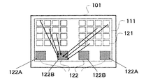
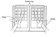
- FIG. 1 is a front view of an information processing terminal according to the first embodiment of the present invention.
- An information processing terminal 101 shown in FIG. 1 is a mobile terminal such as a mobile phone, PHS, or PDA, and it is assumed that a user uses the information processing terminal 101 by holding it with one hand or both hands.
- the information processing terminal 101 has a display input unit in which display means and input means are integrated, and FIG. 1 shows a display screen 111 as the display means.
- the input means is, for example, a touch sensor, and senses a touch operation (contact operation, click operation, long press operation, etc.) from the user.
- touch sensor sensing methods such as a pressure sensitive method and a capacitance method, but this embodiment is not limited to a specific method.
- the information processing terminal 101 executes an application launcher for starting an application program (hereinafter abbreviated as an application), and an application icon (hereinafter, referred to as an application icon) generated by the application launcher is displayed on the display screen 111.
- an application icon hereinafter, referred to as an application icon
- a plurality of (abbreviated as icons) 121 are displayed.
- the icon 121 is an operation target for activating an application, and the corresponding application is activated when a touch operation is performed by the user.
- the setting area 122 includes a first area 122A that is set when the user holds the information processing terminal 101 with both hands and a first area 122A that is set when the user holds the information processing terminal 101 with one hand. 2 regions 122B.
- the first area 122A is used by the user with both hands.
- the range is set so that each thumb of both hands can reach.
- the user when the user holds the information processing terminal 101 with one hand, it is considered that the user often holds the vicinity of the center (near the center of gravity) of the information processing terminal 101 using one hand.
- the user grips the vicinity of the center of the information processing terminal 101 using one hand, it is set within a range where each thumb of one hand reaches.
- the second region 122B may not be near the center of gravity of the information processing terminal 101.
- the setting area 122 is assumed to be invisible on the display screen 111. Furthermore, the setting area 122 may change according to the attitude of the information processing terminal 101.
- FIG. 2 is a block diagram showing a functional configuration of the information processing terminal 101.
- the information processing terminal 101 includes a display input unit 1, a detection unit 2, and a control unit 3.
- the display input unit 1 has a display screen and receives a touch operation on the display screen, and is, for example, a touch panel display.
- the detection unit 2 detects an operation position on the display screen of the display input unit 1 where the user performs a touch operation.
- the detection part 2 shall represent an operation position with the coordinate in the coordinate system preset on the display screen.
- the control unit 3 executes the application and displays the operation target generated by the application on the display screen.
- the operation target is, for example, the icon 121 illustrated in FIG.
- the control unit 3 is a setting region 122 including the operation position detected by the detection unit 2 among the setting regions 122 set in the display screen.
- the operation target on the display screen is moved to the icon collection area corresponding to the number of detection areas.
- the control unit 3 sets all the detection areas as icon collection areas.
- the detection area and the icon collection area may be slightly deviated or their sizes may be slightly different. Thereby, the operability can be further improved by not collecting the icons in the operation position area.
- the case where the state of the display screen before the touch operation is performed is the display screen 111 shown in FIG.
- the control unit 3 moves the icon 121 to the first area 122A as shown in FIG. Move. Further, when the user holds the information processing terminal 101 with one hand and a touch operation is performed on one of the second areas 122B, the control unit 3 touches the icon 121 with the touch as shown in FIG. It moves to the 2nd area
- the display input unit 1 has a display screen and accepts a touch operation on the display screen.
- the detection unit 2 detects the operation position where the touch operation is performed on the display screen.
- the control unit 3 displays an icon 121 that is an operation target on the display screen.
- the control unit 3 sets the icon 121 in the icon collection region corresponding to the number of detection regions that are setting regions including the operation position detected by the detection unit 2 among the plurality of setting regions 122 set in the display screen. Move.
- the icon 121 is moved to an icon collection area corresponding to the number of detection areas that are setting areas including the operation position where the touch operation is performed.
- the number of detection areas reflects the grip style, such as whether the information processing terminal 101 is gripped with both hands or one hand, so the position of the operation target is adjusted to improve operability according to the grip style It becomes possible to do.
- control unit 3 sets all the detection areas as icon collection areas. In this case, since the icon can be moved to or near the place touched by the user, the operability can be further improved.
- the information processing terminal 101 will be described in more detail using a case where there are a plurality of display screens as an example.
- the number of display screens is not particularly limited, but is assumed to be two for simplicity.
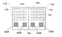
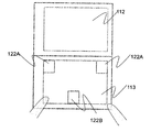
- FIG. 5 is a front view of the information processing terminal according to the present embodiment.
- the information processing terminal 101 has display screens 112 and 113.
- the information processing terminal 101 includes housings 114 and 115, the housing 114 is provided with a display screen 112, and the housing 115 is provided with a display screen 113.
- the casings 114 and 115 are connected to be rotatable (openable and closable) about the rotation shaft 116 using, for example, a hinge mechanism.
- at least one setting area 122 is set on each of the display screens 112 and 113. In the following, it is assumed that one display area 112A and one second area 122B are set on each of the display screens 112 and 113.
- the functional configuration of the information processing terminal in the present embodiment is the same as the configuration shown in FIG.
- a related area is set for each of the setting areas 122, and the predetermined touch operation for moving the icon 121 includes a first operation and a second operation.
- the control unit 3 moves the icon 121 in the related area of the detection area including the operation position where the first operation is performed. Further, when the display input unit 1 receives the second operation, the control unit 3 moves the icons 121 included in all of the related regions of each setting region 122 or all of the display screens 112 and 113.
- the control unit 3 moves the operation target in the display screen including the detection area among the display screens 112 and 113.
- the first operation is a short press
- the second operation is a long press.
- FIG. 6 is a flowchart for explaining the operation of the information processing terminal 101 of this embodiment.
- the application launcher As an initial state of the information processing terminal 101, that is, a state before the touch operation is performed, the application launcher is displayed on both the display screens 112 and 113 as shown in FIG. The person does not touch the display screens 112 and 113.
- the detection unit 2 detects the touched touch coordinates and notifies the control unit 3 of the touch coordinates (step 201). . Note that the detection unit 2 continues to notify the touch coordinates while being touched, and further changes the touch coordinates notified in accordance with the change when the touch coordinates change.
- control unit 3 determines whether the touch coordinates are included in the setting area 122. It is assumed that the control unit 3 holds the coordinates of the setting area 122 in advance. When the touch coordinates are not included in the setting area 122, the control unit 3 ends the process without doing anything (step 202).
- the control unit 3 monitors the touch coordinates and the touch coordinates are the first coordinates. It is determined whether it has not been changed within a certain time (hereinafter referred to as T1 seconds). If the touch coordinates are changed within T1 seconds, that is, if the user moves or releases the finger before T1 seconds elapse, the processing ends without doing anything (step 203).
- control unit 3 determines that a short press has been performed. And the control part 3 specifies the touched display screen (henceforth the display screen 112) based on the touch coordinate. The control unit 3 reduces the icon 121 displayed on the specified display screen 112 and moves it to the touched setting area (step S204).
- FIG. 7 is a diagram showing the information processing terminal 101 in a state where icons are reduced and displayed.
- an icon 123 is a reduced display of the icons 121 included in the display screen 112.
- the icon 123 at the touch coordinates is selected.
- the icon 121 corresponding to the icon 123 in the selected state is shown in a solid color.
- control unit 3 determines whether or not the touch coordinates are changed within a predetermined second predetermined time (T2 seconds). If the touch coordinates are changed within T2 seconds, that is, if the user moves or releases the finger before T2 seconds elapse, the processing is terminated without doing anything (step 205).
- the control unit 3 determines that a long press has been performed. Then, the control unit 3 reduces the icon 121 displayed on the display screen 113 and further moves it to the touched setting area, so that the icon 121 displayed on all of the display screens 112 and 113 is changed. A reduction display is performed in the touched setting area 122 (step 206).
- FIG. 8 is a diagram showing the information processing terminal 101 in a state in which icons for two screens are reduced and displayed.
- an icon 124 is a reduced display of what is included in all of the display screens 112 and 113 of the icon 121. If the user moves his / her finger while touching the display screen 112 in this state, the icon 124 at the touch coordinates is selected. In FIG. 8, the icon 121 corresponding to the selected icon 124 is filled.
- the detection area that is the touched setting area 122 is the first area 122A.
- the setting area 122 includes the second area 122B.
- the above operation can be performed even when the setting area 122 touched is the second area 122B.
- the information processing terminal 101 in a state in which icons for two screens are reduced and displayed when the vicinity of the center of the information processing terminal 101 is held with one hand is as shown in FIG.
- the control unit 3 displays the icon 121 displayed on each of the display screens 112 and 113 on the display screen 112 or 113 displayed on the display screen 112 or 113 in step S204. Move to the included detection area.
- the information processing terminal 101 is as shown in FIG. In this case, since all the icons 121 are reduced and displayed in the short press operation, the display state does not change even if the long press is performed.
- the icon 123 ′ is a reduced display of the icons 121 included in the display screen 113.
- FIG. 11 is a flowchart for explaining the operation of the information processing terminal 101 when the user releases the finger touched on the display screen.
- the detection unit 2 stops the notification of touch coordinates (step 501).
- the control unit 3 determines the touch coordinates received last as the release coordinates that are the coordinates at which the user has released the finger. And the control part 3 confirms the present display state. Specifically, the control unit 3 confirms as a display state whether or not the icons 121 for one screen or two screens are displayed in a reduced size (step S502).
- the control unit 3 determines whether or not the release coordinate matches the icon coordinate corresponding to the icon 121 (step 507). If the release coordinates coincide with the icon coordinates, an application corresponding to the icon is started (step S505). If the release coordinates differ from the icon coordinates, the process ends without doing anything. Note that the processing when the icon is not reduced is equivalent to the standard operation of the application launcher.
- step S502 If it is determined in step S502 that the icon is displayed in a reduced size, the control unit 3 determines whether any one of the reduced icons is selected (step 503).
- control unit 3 releases the reduced display state (step 506), and then ends the process.
- control unit 3 cancels the reduced display state (step 506), and then activates the application corresponding to the icon in the selected state (step 505). .
- the setting area does not always have to be set.
- the icon set function for moving icons described in the present embodiment does not have to be ON (enabled).
- the displayed application assigns a function different from the icon set function to the area corresponding to the setting area, the function and the icon set function are mistakenly executed at the same time. May be reduced.
- the control unit 3 displays a switching operation target for switching ON / OFF of the icon set function on the display screen, and based on the detection result of the detection unit 2, the control unit 3 performs the switching operation target.
- the icon setting area may be switched ON / OFF.
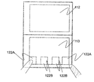
- FIG. 12A is a diagram illustrating an example of an operation target for switching.
- the icon set function is OFF and the setting area is not set.
- a bar 125 is displayed as an operation object for switching at the lower part of each of the display screens 112 and 113.
- the user drags the area in which the bar 125 is displayed from the edge of the screen toward the screen as shown in FIG. 12B, so that the icon collection function is turned on, and the setting area 122 is set as shown in FIG. be able to. Further, the setting area 122 can be hidden as shown in FIG. 12A by dragging the user in the reverse direction. Thereby, since it can be explicitly shown whether or not the setting area is set, erroneous operations can be reduced.
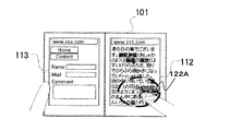
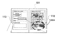
- FIG. 13 is a diagram illustrating an information processing terminal when a Web browser is being executed.
- the control screen 3 displays separate websites on the display screens 112 and 113, and the state after the user touches the first area 122A of the display screen 112 for T1 seconds. It is shown.
- the icon is the operation target
- the link, input form, URL (Uniform Resource Locator) input field, etc. are the operation target.
- the links and URL input fields that are the operation targets in the display screen 112 are reduced and displayed in the first area 122A.
- processing equivalent to that performed when the operation target is touched during normal display is performed. For example, when a user releases a finger while a reduced link is selected, the browser displays a linked Web page corresponding to the link.
- a related area is set for each setting area 122.
- the control unit 3 moves the operation target included in the related area of the detection area. Accordingly, it is possible to reduce the movement of the operation target that is not required by the user, and thus it is possible to further improve the operability.
- the predetermined touch operation includes a first operation and a second operation.
- the control unit 3 moves the operation target included in the related area of the detection area.
- the control unit 3 moves the operation target included in all the related areas of the setting area. Therefore, since the user can select the operation target to be moved according to the situation, the operability can be further improved.
- control unit 3 moves the operation target in the display screen including the detection area in the display screen. In this case, since it is possible to reduce the movement of unnecessary operation objects such as operation objects other than the display screen that is not visually recognized by the user, it is possible to further improve operability.
- control unit 3 describes an information processing terminal that changes an operation target to be moved according to the display state of an application.
- the applications executed by the control unit 3 include a full screen mode for displaying display information over the display screens 112 and 113 and a single screen mode for displaying on one of the display screens 112 and 113.
- the operation target such as the icon described in the first and second embodiments is included in the display information generated by the application.
- the full screen mode is also called a multiple screen mode.
- the control unit 3 executes the application in one of the full screen mode and the single screen mode. Note that the application mode may be switched during execution of the application. Further, the control unit 3 may execute the application individually for each of the display screens 112 and 113 and display the display information of each application on the display screen for the application. In this case, display information of different applications is displayed on each of the display screens 112 and 113.
- control unit 3 moves the operation target included in both the display screens 112 and 113 regardless of whether the detection area is the first area 122A or the second area 122B.
- the control unit 3 moves the operation target in the display screen including the first area 122A to each of the first areas 122A as illustrated in FIG. Is done.
- the control unit 3 moves all operation objects to the second area 122A, which is the detection area, as illustrated in FIG.
- the control unit 3 moves all the operation targets to the second area 122B, which is the detection area, as illustrated in FIG.
- control unit 3 selects the operation target in the display screen including the detection area among the display screens 112 and 113 when the detection area is the first area 122A. Move. On the other hand, when the detection area is the second area 122B, the control unit 3 moves the operation target included in both the display screens 112 and 113.
- the control unit 3 sets the operation target in the display screen including the detection area to the first area 122A that is the detection area, as shown in FIG. Move.
- the control unit 3 performs the same process as when the application is executed in the full screen mode. become.
- the control unit 3 moves all the operation targets in the display screens 112 and 113 and moves the application to the single screen mode.
- the operation target in the display screen including the detection area is moved. For this reason, since it becomes possible to move only the operation target corresponding to the application which the user is using, it becomes possible to improve operativity more.
- the control unit 3 moves the operation target included in all of the display screens 112 and 113 when the detection area is the second area 122B.
- the detection area is the first area 122A
- the operation target in the display screen including the detection area is moved. For this reason, when the user is holding the information processing terminal with one hand, a plurality of applications can be operated without changing the holding style.
- FIG. 19 is a diagram illustrating a functional configuration of the information processing terminal 101 according to the present embodiment.
- the information processing terminal 101 further includes a posture detection unit 4 in addition to the configuration illustrated in FIG. 2.
- the posture detection unit 4 includes a six-axis sensor, an acceleration sensor, and the like, and detects the posture of the information processing terminal 101.
- the posture of the information processing terminal 101 is, for example, the inclination of the display screens 112 and 113 with respect to the horizontal plane.
- the control unit 3 sets the setting area 122 at a position corresponding to the detection result of the posture detection unit 4. More specifically, the control unit 3 determines whether the information processing terminal 101 is held vertically or horizontally based on the detection result of the posture detection unit 4.
- FIG. 20A is a front view of the information processing terminal 101 held vertically.
- the display screens 112 and 113 are gripped so as to be arranged vertically as viewed from the user.
- the first area 122A is set near both sides of the lower side of the display screen 113 below the user
- the second area 122B is set near the center of the lower side of the display screen 113. One is set.
- the positions and numbers of the first region 122A and the second region 122B shown in FIG. 20A are merely examples.
- the first area 122A may be set near both sides of the upper side of the display screen 113, and there are two second areas 122B as shown in FIG. 20C. Also good.
- the information processing terminal 101 (for example, FIG. 1 or FIG. 5) of the first to third embodiments is an example of a case where the information processing terminal 101 is held horizontally.
- the processing when a predetermined touch operation is performed on the setting area 122 is the same as that of the information processing terminal 101 of the first to third embodiments.
- the control unit 3 may change the related area for the setting area 122 according to the position of the setting area 122.
- the setting area is set at a position corresponding to the attitude of the information processing terminal 101. Therefore, even if the position of the hand that is easy for the user to grip changes according to the posture of the information processing terminal 101, the position of the operation target can be adjusted so that the operability is improved.
Abstract
Description
2 検出部
3 制御部
4 姿勢検出部
101 情報処理端末
111~113 表示画面
114、115 筐体 DESCRIPTION OF
Claims (10)
- 表示画面を有し、前記表示画面に対するタッチ操作を受け付ける表示入力部と、
前記表示画面上における、前記タッチ操作が行われた操作位置を検出する検出部と、
前記表示画面に操作対象を表示し、また、前記表示画面内に設定された複数の設定領域のうち、前記検出部が検出した操作位置を含む設定領域である検出領域の数に応じた集合領域に、前記操作対象を移動させる制御部と、を有する情報処理端末。 A display input unit having a display screen and receiving a touch operation on the display screen;
A detection unit for detecting an operation position where the touch operation is performed on the display screen;
An operation area is displayed on the display screen, and a set area corresponding to the number of detection areas that are setting areas including the operation position detected by the detection unit among a plurality of setting areas set in the display screen And an information processing terminal having a control unit that moves the operation target. - 請求項1に記載の情報処理端末において、
各設定領域に対して関連領域が設定され、
前記制御部は、前記検出領域の関連領域に含まれる前記操作対象を移動させる、情報処理端末。 The information processing terminal according to claim 1,
A related area is set for each setting area,
The control unit is an information processing terminal that moves the operation target included in a related area of the detection area. - 請求項2に記載の情報処理端末において、
前記タッチ操作には、第1操作と第2操作とがあり、
前記制御部は、前記表示入力部が前記第1操作を受け付けた場合、前記検出領域の関連領域に含まれる前記操作対象を移動させ、前記表示入力部が前記第2操作を受け付けた場合、各設定領域の関連領域の全てに含まれる前記操作対象を移動させる、情報処理端末。 The information processing terminal according to claim 2,
The touch operation includes a first operation and a second operation,
When the display input unit accepts the first operation, the control unit moves the operation target included in the related area of the detection region, and when the display input unit accepts the second operation, An information processing terminal that moves the operation target included in all the related areas of the setting area. - 請求項1ないし3のいずれか1項に記載の情報処理端末において、
前記制御部は、前記検出領域の全てを前記集合領域とする、情報処理端末。 The information processing terminal according to any one of claims 1 to 3,
The control unit is an information processing terminal in which all the detection areas are the collection areas. - 請求項1ないし4のいずれか1項に記載の情報処理端末において、
前記表示画面は、複数あり、各表示画面には、前記設定領域が少なくとも一つ設定されている、情報処理端末。 The information processing terminal according to any one of claims 1 to 4,
An information processing terminal, wherein there are a plurality of display screens, and at least one setting area is set on each display screen. - 請求項5に記載の情報処理端末において、
前記制御部は、前記表示画面のうち前記検出領域を含む表示画面内の前記操作対象を移動させる、情報処理端末。 The information processing terminal according to claim 5,
The control unit is an information processing terminal that moves the operation target in a display screen including the detection area in the display screen. - 請求項6に記載の情報処理端末において、
前記制御部は、前記操作対象を含む表示情報を生成するアプリケーションを、前記表示情報を前記複数の表示画面に渡って表示する複数画面モードで実行している場合、当該複数の表示画面内の全ての操作対象を移動させ、前記アプリケーションを、前記表示情報を前記複数の表示画面のいずれかに表示する一画面モードで実行している場合、前記検出領域を含む表示画面内の操作対象を移動させる、情報処理端末。 The information processing terminal according to claim 6,
When the control unit is executing an application that generates display information including the operation target in a multi-screen mode in which the display information is displayed across the plurality of display screens, all of the plurality of display screens are displayed. When the application is executed in a single screen mode in which the display information is displayed on any of the plurality of display screens, the operation target in the display screen including the detection area is moved. Information processing terminal. - 請求項7に記載の情報処理端末において、
前記設定領域には、第1領域と第2領域とがあり、
前記制御部は、前記アプリケーションが前記一画面モードで実行されている場合、前記検出領域が前記第1領域であると、前記検出領域を含む表示画面内の操作対象を移動させ、前記検出領域が前記第2領域であると、前記複数の表示画面の全てに含まれる操作対象を移動させる、情報処理端末。 The information processing terminal according to claim 7,
The setting area includes a first area and a second area,
When the application is executed in the one-screen mode, the control unit moves an operation target in a display screen including the detection area, and the detection area is An information processing terminal that moves an operation target included in all of the plurality of display screens in the second area. - 請求項1ないし8のいずれか1項に記載の情報処理端末において、
当該情報処理端末の姿勢を検出する姿勢検出部をさらに有し、
前記制御部は、前記姿勢検出部の検出結果に応じた位置に前記設定領域を設定する、情報処理端末。 The information processing terminal according to any one of claims 1 to 8,
It further has a posture detection unit that detects the posture of the information processing terminal,
The said control part is an information processing terminal which sets the said setting area | region in the position according to the detection result of the said attitude | position detection part. - 表示画面を有する情報処理端末の操作制御方法であって、
前記表示画面に操作対象を表示し、
前記表示画面に対するタッチ操作を受け付け、
前記表示画面上における、前記タッチ操作が行われた操作位置を検出し、
前記表示画面内に設定された複数の設定領域のうち、前記検出した操作位置を含む設定領域である検出領域の数に応じた集合領域に、前記操作対象を移動させる、操作制御方法。 An operation control method for an information processing terminal having a display screen,
The operation target is displayed on the display screen,
Receiving a touch operation on the display screen;
Detecting an operation position where the touch operation is performed on the display screen;
An operation control method for moving the operation target to a set area corresponding to the number of detection areas that are setting areas including the detected operation position among a plurality of setting areas set in the display screen.
Priority Applications (4)
| Application Number | Priority Date | Filing Date | Title |
|---|---|---|---|
| US13/636,006 US9372623B2 (en) | 2010-04-30 | 2011-03-17 | Information processing terminal and operation control method for same |
| EP11774728.7A EP2565764B1 (en) | 2010-04-30 | 2011-03-17 | Information processing terminal and operation control method for same |
| JP2012512716A JP5817716B2 (en) | 2010-04-30 | 2011-03-17 | Information processing terminal and operation control method thereof |
| CN201180021924.4A CN102870084B (en) | 2010-04-30 | 2011-03-17 | The information processing terminal and the method for controlling operation thereof for this information processing terminal |
Applications Claiming Priority (2)
| Application Number | Priority Date | Filing Date | Title |
|---|---|---|---|
| JP2010-105397 | 2010-04-30 | ||
| JP2010105397 | 2010-04-30 |
Publications (1)
| Publication Number | Publication Date |
|---|---|
| WO2011135944A1 true WO2011135944A1 (en) | 2011-11-03 |
Family
ID=44861265
Family Applications (1)
| Application Number | Title | Priority Date | Filing Date |
|---|---|---|---|
| PCT/JP2011/056364 WO2011135944A1 (en) | 2010-04-30 | 2011-03-17 | Information processing terminal and operation control method for same |
Country Status (5)
| Country | Link |
|---|---|
| US (1) | US9372623B2 (en) |
| EP (1) | EP2565764B1 (en) |
| JP (1) | JP5817716B2 (en) |
| CN (1) | CN102870084B (en) |
| WO (1) | WO2011135944A1 (en) |
Cited By (20)
| Publication number | Priority date | Publication date | Assignee | Title |
|---|---|---|---|---|
| CN102609205A (en) * | 2012-02-07 | 2012-07-25 | 深圳桑菲消费通信有限公司 | Method for implementing omni-directional sliding on mobile terminal screen |
| CN102855066A (en) * | 2012-09-26 | 2013-01-02 | 东莞宇龙通信科技有限公司 | Terminal and terminal control method |
| CN103024156A (en) * | 2012-11-29 | 2013-04-03 | 广东欧珀移动通信有限公司 | Method, system and mobile terminal for realizing one-handed mobile terminal operation |
| CN103019568A (en) * | 2012-12-21 | 2013-04-03 | 东莞宇龙通信科技有限公司 | Terminal and icon display method |
| CN103257818A (en) * | 2012-02-20 | 2013-08-21 | 联想(北京)有限公司 | Method and device for one-handed operation of icon on touch screen |
| WO2013176472A1 (en) | 2012-05-21 | 2013-11-28 | Samsung Electronics Co., Ltd. | Method and apparatus of controlling user interface using touch screen |
| CN103677556A (en) * | 2012-09-24 | 2014-03-26 | 北京三星通信技术研究有限公司 | Method and device for locating application program quickly |
| JP2014085792A (en) * | 2012-10-23 | 2014-05-12 | Fuji Xerox Co Ltd | Information processing device and program |
| CN104049894A (en) * | 2014-06-09 | 2014-09-17 | 联想(北京)有限公司 | Information processing method and electronic equipment |
| JP2015518984A (en) * | 2012-06-05 | 2015-07-06 | シャオミ・インコーポレイテッド | User interface interaction method, apparatus, touch screen device, program, and recording medium used in touch screen device |
| CN104932825A (en) * | 2015-06-15 | 2015-09-23 | 金陵科技学院 | Method for automatically sensing left hand/right hand to operate mobile phone and determining moving thermal region of thumb |
| CN105204744A (en) * | 2015-09-28 | 2015-12-30 | 北京金山安全软件有限公司 | Method and device for starting application program and electronic equipment |
| CN105630371A (en) * | 2015-06-24 | 2016-06-01 | 宇龙计算机通信科技(深圳)有限公司 | Single-hand operation method and apparatus for terminal |
| US9360952B2 (en) | 2012-03-08 | 2016-06-07 | Lg Electronics Inc. | Mobile terminal and method to change display screen |
| EP2592537A3 (en) * | 2011-11-11 | 2016-08-24 | Samsung Electronics Co., Ltd | Method and apparatus for designating entire area using partial area touch in a portable equipment |
| JP2016162447A (en) * | 2015-03-05 | 2016-09-05 | 三星ディスプレイ株式會社Samsung Display Co.,Ltd. | Display device |
| CN106406734A (en) * | 2012-09-17 | 2017-02-15 | 华为终端有限公司 | Touch operation processing method and terminal equipment |
| US9684403B2 (en) | 2012-03-19 | 2017-06-20 | Mediatek Inc. | Method, device, and computer-readable medium for changing size of touch permissible region of touch screen |
| EP2624119B1 (en) * | 2012-02-01 | 2018-03-07 | LG Electronics Inc. -1- | Electronic device and method of controlling the same |
| JP2019505858A (en) * | 2017-01-03 | 2019-02-28 | ゼットティーイー コーポレーションZte Corporation | Screen content switching method and double screen mobile terminal |
Families Citing this family (19)
| Publication number | Priority date | Publication date | Assignee | Title |
|---|---|---|---|---|
| US9417754B2 (en) * | 2011-08-05 | 2016-08-16 | P4tents1, LLC | User interface system, method, and computer program product |
| CN104049879A (en) * | 2013-03-14 | 2014-09-17 | 中兴通讯股份有限公司 | Touch terminal and tooltip positioning method of touch terminal |
| CN103176744B (en) * | 2013-04-12 | 2018-08-07 | 努比亚技术有限公司 | A kind of display equipment and its information processing method |
| CN103353826B (en) * | 2013-04-16 | 2017-05-24 | 努比亚技术有限公司 | Display equipment and information processing method thereof |
| US10691291B2 (en) * | 2013-05-24 | 2020-06-23 | Samsung Electronics Co., Ltd. | Method and apparatus for displaying picture on portable device |
| US9696882B2 (en) * | 2013-08-28 | 2017-07-04 | Lenovo (Beijing) Co., Ltd. | Operation processing method, operation processing device, and control method |
| CN104750400B (en) * | 2013-12-27 | 2017-12-15 | 华为技术有限公司 | The optimization operation method and device of terminal interface |
| KR20150099297A (en) * | 2014-02-21 | 2015-08-31 | 삼성전자주식회사 | Method and apparatus for displaying screen on electronic devices |
| CN105094660A (en) * | 2014-05-22 | 2015-11-25 | 中国移动通信集团公司 | Terminal screen adjusting method and device, and terminal |
| CN105204756A (en) * | 2014-06-30 | 2015-12-30 | 阿尔卡特朗讯 | Method and device used for operating screen of touch screen device |
| JP2016224523A (en) * | 2015-05-27 | 2016-12-28 | 京セラ株式会社 | Portable terminal |
| CN105744054A (en) * | 2015-12-31 | 2016-07-06 | 宇龙计算机通信科技(深圳)有限公司 | Mobile terminal control method and mobile terminal |
| CN106502521A (en) * | 2016-09-12 | 2017-03-15 | 珠海格力电器股份有限公司 | The display methods in toggle screen direction, device and the handheld device with the device |
| CN106843632A (en) * | 2016-11-30 | 2017-06-13 | 广州视源电子科技股份有限公司 | The display methods and system of a kind of icon |
| US20190056857A1 (en) * | 2017-08-18 | 2019-02-21 | Microsoft Technology Licensing, Llc | Resizing an active region of a user interface |
| US11301124B2 (en) | 2017-08-18 | 2022-04-12 | Microsoft Technology Licensing, Llc | User interface modification using preview panel |
| US10417991B2 (en) | 2017-08-18 | 2019-09-17 | Microsoft Technology Licensing, Llc | Multi-display device user interface modification |
| US11237699B2 (en) | 2017-08-18 | 2022-02-01 | Microsoft Technology Licensing, Llc | Proximal menu generation |
| US11487425B2 (en) * | 2019-01-17 | 2022-11-01 | International Business Machines Corporation | Single-hand wide-screen smart device management |
Citations (3)
| Publication number | Priority date | Publication date | Assignee | Title |
|---|---|---|---|---|
| JP2001134382A (en) * | 1999-11-04 | 2001-05-18 | Sony Corp | Graphic processor |
| JP2008250620A (en) * | 2007-03-30 | 2008-10-16 | Fuji Xerox Co Ltd | Display device and program |
| JP2010105397A (en) | 2008-10-30 | 2010-05-13 | Lg Hausys Ltd | Transfer film for in-mold injection |
Family Cites Families (20)
| Publication number | Priority date | Publication date | Assignee | Title |
|---|---|---|---|---|
| JP4280314B2 (en) | 1997-11-27 | 2009-06-17 | 富士フイルム株式会社 | Device operating device having a screen display unit |
| US20020018051A1 (en) * | 1998-09-15 | 2002-02-14 | Mona Singh | Apparatus and method for moving objects on a touchscreen display |
| JP2002140148A (en) | 2000-10-30 | 2002-05-17 | Nagano Fujitsu Component Kk | Key board |
| US7231609B2 (en) * | 2003-02-03 | 2007-06-12 | Microsoft Corporation | System and method for accessing remote screen content |
| JP2004355606A (en) | 2003-02-14 | 2004-12-16 | Sony Corp | Information processor, information processing method, and program |
| JP2006148536A (en) | 2004-11-19 | 2006-06-08 | Sony Corp | Portable terminal, and character inputting method and program |
| JP2007036544A (en) | 2005-07-26 | 2007-02-08 | Yamaha Corp | Portable terminal |
| JP2009158989A (en) | 2006-04-06 | 2009-07-16 | Nikon Corp | Camera |
| JP4699955B2 (en) | 2006-07-21 | 2011-06-15 | シャープ株式会社 | Information processing device |
| KR20080068781A (en) * | 2007-01-20 | 2008-07-24 | 엘지전자 주식회사 | Electronic device with touch screen and method of displaying information using same |
| JP4500845B2 (en) | 2007-11-13 | 2010-07-14 | シャープ株式会社 | Information display device, information display method, program, and recording medium |
| JP4605478B2 (en) * | 2007-12-19 | 2011-01-05 | ソニー株式会社 | Information processing apparatus, display control method, and display control program |
| JP4364273B2 (en) * | 2007-12-28 | 2009-11-11 | パナソニック株式会社 | Portable terminal device, display control method, and display control program |
| KR101020029B1 (en) * | 2008-07-02 | 2011-03-09 | 삼성전자주식회사 | Mobile terminal having touch screen and method for inputting key using touch thereof |
| JP2010020601A (en) | 2008-07-11 | 2010-01-28 | Nec Corp | Mobile terminal, method of arranging item of touch panel, and program |
| JP4666053B2 (en) * | 2008-10-28 | 2011-04-06 | ソニー株式会社 | Information processing apparatus, information processing method, and program |
| JP5066055B2 (en) * | 2008-10-28 | 2012-11-07 | 富士フイルム株式会社 | Image display device, image display method, and program |
| CN104298398A (en) * | 2008-12-04 | 2015-01-21 | 三菱电机株式会社 | Display input device |
| KR101587211B1 (en) * | 2009-05-25 | 2016-01-20 | 엘지전자 주식회사 | Mobile Terminal And Method Of Controlling Same |
| JP2009261024A (en) | 2009-08-10 | 2009-11-05 | Fujifilm Corp | Image pick-up device equipped with display device |
-
2011
- 2011-03-17 CN CN201180021924.4A patent/CN102870084B/en active Active
- 2011-03-17 EP EP11774728.7A patent/EP2565764B1/en active Active
- 2011-03-17 US US13/636,006 patent/US9372623B2/en active Active
- 2011-03-17 WO PCT/JP2011/056364 patent/WO2011135944A1/en active Application Filing
- 2011-03-17 JP JP2012512716A patent/JP5817716B2/en active Active
Patent Citations (3)
| Publication number | Priority date | Publication date | Assignee | Title |
|---|---|---|---|---|
| JP2001134382A (en) * | 1999-11-04 | 2001-05-18 | Sony Corp | Graphic processor |
| JP2008250620A (en) * | 2007-03-30 | 2008-10-16 | Fuji Xerox Co Ltd | Display device and program |
| JP2010105397A (en) | 2008-10-30 | 2010-05-13 | Lg Hausys Ltd | Transfer film for in-mold injection |
Non-Patent Citations (1)
| Title |
|---|
| See also references of EP2565764A4 |
Cited By (38)
| Publication number | Priority date | Publication date | Assignee | Title |
|---|---|---|---|---|
| US9652133B2 (en) | 2011-11-11 | 2017-05-16 | Samsung Electronics Co., Ltd. | Method and apparatus for designating entire area using partial area touch in a portable equipment |
| EP2592537A3 (en) * | 2011-11-11 | 2016-08-24 | Samsung Electronics Co., Ltd | Method and apparatus for designating entire area using partial area touch in a portable equipment |
| EP2624119B1 (en) * | 2012-02-01 | 2018-03-07 | LG Electronics Inc. -1- | Electronic device and method of controlling the same |
| CN102609205A (en) * | 2012-02-07 | 2012-07-25 | 深圳桑菲消费通信有限公司 | Method for implementing omni-directional sliding on mobile terminal screen |
| CN103257818A (en) * | 2012-02-20 | 2013-08-21 | 联想(北京)有限公司 | Method and device for one-handed operation of icon on touch screen |
| US9360952B2 (en) | 2012-03-08 | 2016-06-07 | Lg Electronics Inc. | Mobile terminal and method to change display screen |
| EP2637086B1 (en) * | 2012-03-08 | 2018-05-02 | LG Electronics Inc. | Mobile terminal |
| US9684403B2 (en) | 2012-03-19 | 2017-06-20 | Mediatek Inc. | Method, device, and computer-readable medium for changing size of touch permissible region of touch screen |
| EP2852882A4 (en) * | 2012-05-21 | 2016-01-27 | Samsung Electronics Co Ltd | Method and apparatus of controlling user interface using touch screen |
| KR20130129864A (en) * | 2012-05-21 | 2013-11-29 | 삼성전자주식회사 | A method and apparatus for controlling a user interface using a touch screen |
| CN104321736A (en) * | 2012-05-21 | 2015-01-28 | 三星电子株式会社 | Method and apparatus of controlling user interface using touch screen |
| US10338705B2 (en) | 2012-05-21 | 2019-07-02 | Samsung Electronics Co., Ltd. | Method and apparatus of controlling user interface using touch screen |
| KR102094695B1 (en) | 2012-05-21 | 2020-03-31 | 삼성전자주식회사 | A method and apparatus for controlling a user interface using a touch screen |
| CN104321736B (en) * | 2012-05-21 | 2018-11-13 | 三星电子株式会社 | Method and apparatus for carrying out control user interface by using touch screen |
| US11061496B2 (en) | 2012-05-21 | 2021-07-13 | Samsung Electronics Co., Ltd. | Method and apparatus of controlling user interface using touch screen |
| WO2013176472A1 (en) | 2012-05-21 | 2013-11-28 | Samsung Electronics Co., Ltd. | Method and apparatus of controlling user interface using touch screen |
| JP2015518984A (en) * | 2012-06-05 | 2015-07-06 | シャオミ・インコーポレイテッド | User interface interaction method, apparatus, touch screen device, program, and recording medium used in touch screen device |
| US9910558B2 (en) | 2012-06-05 | 2018-03-06 | Beijing Xiaomi Technology Co., Ltd. | Methods and devices for user interactive interfaces on touchscreens |
| CN106406734A (en) * | 2012-09-17 | 2017-02-15 | 华为终端有限公司 | Touch operation processing method and terminal equipment |
| US10754539B2 (en) | 2012-09-17 | 2020-08-25 | Huawei Device Co., Ltd. | Touch Operation Processing Method and Terminal Device |
| CN106406734B (en) * | 2012-09-17 | 2019-10-25 | 华为终端有限公司 | Touch operation processing method and terminal device |
| US11112902B2 (en) | 2012-09-17 | 2021-09-07 | Huawei Device Co., Ltd. | Touch operation processing method and terminal device |
| US10296204B2 (en) | 2012-09-17 | 2019-05-21 | Huawei Device Co., Ltd. | Touch operation processing method and terminal device |
| US11592924B2 (en) | 2012-09-17 | 2023-02-28 | Huawei Device Co., Ltd. | Touch operation processing method and terminal device |
| CN103677556A (en) * | 2012-09-24 | 2014-03-26 | 北京三星通信技术研究有限公司 | Method and device for locating application program quickly |
| CN102855066A (en) * | 2012-09-26 | 2013-01-02 | 东莞宇龙通信科技有限公司 | Terminal and terminal control method |
| JP2014085792A (en) * | 2012-10-23 | 2014-05-12 | Fuji Xerox Co Ltd | Information processing device and program |
| CN103024156A (en) * | 2012-11-29 | 2013-04-03 | 广东欧珀移动通信有限公司 | Method, system and mobile terminal for realizing one-handed mobile terminal operation |
| CN103019568A (en) * | 2012-12-21 | 2013-04-03 | 东莞宇龙通信科技有限公司 | Terminal and icon display method |
| CN104049894A (en) * | 2014-06-09 | 2014-09-17 | 联想(北京)有限公司 | Information processing method and electronic equipment |
| JP2016162447A (en) * | 2015-03-05 | 2016-09-05 | 三星ディスプレイ株式會社Samsung Display Co.,Ltd. | Display device |
| US10705716B2 (en) | 2015-03-05 | 2020-07-07 | Samsung Display Co., Ltd. | Display apparatus |
| CN104932825A (en) * | 2015-06-15 | 2015-09-23 | 金陵科技学院 | Method for automatically sensing left hand/right hand to operate mobile phone and determining moving thermal region of thumb |
| CN105630371A (en) * | 2015-06-24 | 2016-06-01 | 宇龙计算机通信科技(深圳)有限公司 | Single-hand operation method and apparatus for terminal |
| CN105204744B (en) * | 2015-09-28 | 2018-10-19 | 北京金山安全软件有限公司 | Method and device for starting application program and electronic equipment |
| CN105204744A (en) * | 2015-09-28 | 2015-12-30 | 北京金山安全软件有限公司 | Method and device for starting application program and electronic equipment |
| JP2019505858A (en) * | 2017-01-03 | 2019-02-28 | ゼットティーイー コーポレーションZte Corporation | Screen content switching method and double screen mobile terminal |
| US10649494B2 (en) | 2017-01-03 | 2020-05-12 | Zte Corporation | Screen content switching method and double-screen mobile terminal |
Also Published As
| Publication number | Publication date |
|---|---|
| CN102870084A (en) | 2013-01-09 |
| US20130009903A1 (en) | 2013-01-10 |
| JPWO2011135944A1 (en) | 2013-07-18 |
| EP2565764A4 (en) | 2016-08-10 |
| US9372623B2 (en) | 2016-06-21 |
| JP5817716B2 (en) | 2015-11-18 |
| CN102870084B (en) | 2015-08-19 |
| EP2565764A1 (en) | 2013-03-06 |
| EP2565764B1 (en) | 2020-10-07 |
Similar Documents
| Publication | Publication Date | Title |
|---|---|---|
| JP5817716B2 (en) | Information processing terminal and operation control method thereof | |
| US9671880B2 (en) | Display control device, display control method, and computer program | |
| JP5708644B2 (en) | Information processing terminal and control method thereof | |
| US20210303150A1 (en) | Electronic device with gesture-based task management | |
| US8775966B2 (en) | Electronic device and method with dual mode rear TouchPad | |
| JP5691464B2 (en) | Information processing device | |
| EP2860622B1 (en) | Electronic device and controlling method and program therefor | |
| US20130215060A1 (en) | Mobile terminal apparatus and display method for touch panel in mobile terminal apparatus | |
| WO2012043111A1 (en) | Information processing terminal and control method therefor | |
| US20120212418A1 (en) | Mobile terminal and display method | |
| JP6319298B2 (en) | Information terminal, display control method and program thereof | |
| JP2013546110A (en) | Enhanced interpretation of input events that occur when interacting with a computing device that uses the motion of the computing device | |
| US9733667B2 (en) | Information processing device, information processing method and recording medium | |
| JP5846129B2 (en) | Information processing terminal and control method thereof | |
| JP6109788B2 (en) | Electronic device and method of operating electronic device | |
| US10671269B2 (en) | Electronic device with large-size display screen, system and method for controlling display screen | |
| WO2012161237A1 (en) | Information processing device and control method therefor | |
| EP3457672B1 (en) | Portable electronic device, touch operation processing method, and program | |
| US20110012843A1 (en) | Touch-controlled electronic apparatus and related control method | |
| JP6217633B2 (en) | Mobile terminal device, control method for mobile terminal device, and program | |
| JP2014016743A (en) | Information processing device, information processing device control method and information processing device control program | |
| JP5855481B2 (en) | Information processing apparatus, control method thereof, and control program thereof | |
| JP2006039819A (en) | Coordinate input device |
Legal Events
| Date | Code | Title | Description |
|---|---|---|---|
| WWE | Wipo information: entry into national phase |
Ref document number: 201180021924.4 Country of ref document: CN |
|
| 121 | Ep: the epo has been informed by wipo that ep was designated in this application |
Ref document number: 11774728 Country of ref document: EP Kind code of ref document: A1 |
|
| WWE | Wipo information: entry into national phase |
Ref document number: 13636006 Country of ref document: US |
|
| WWE | Wipo information: entry into national phase |
Ref document number: 2011774728 Country of ref document: EP |
|
| WWE | Wipo information: entry into national phase |
Ref document number: 2012512716 Country of ref document: JP |
|
| NENP | Non-entry into the national phase |
Ref country code: DE |
|
| WWE | Wipo information: entry into national phase |
Ref document number: 9981/CHENP/2012 Country of ref document: IN |