WO2011033763A1 - Damping device and disk drive equipped with damping device - Google Patents
Damping device and disk drive equipped with damping device Download PDFInfo
- Publication number
- WO2011033763A1 WO2011033763A1 PCT/JP2010/005623 JP2010005623W WO2011033763A1 WO 2011033763 A1 WO2011033763 A1 WO 2011033763A1 JP 2010005623 W JP2010005623 W JP 2010005623W WO 2011033763 A1 WO2011033763 A1 WO 2011033763A1
- Authority
- WO
- WIPO (PCT)
- Prior art keywords
- auxiliary mass
- main frame
- damping device
- vibration damping
- transmission force
- Prior art date
Links
Images


Classifications
-
- G—PHYSICS
- G11—INFORMATION STORAGE
- G11B—INFORMATION STORAGE BASED ON RELATIVE MOVEMENT BETWEEN RECORD CARRIER AND TRANSDUCER
- G11B33/00—Constructional parts, details or accessories not provided for in the other groups of this subclass
- G11B33/02—Cabinets; Cases; Stands; Disposition of apparatus therein or thereon
- G11B33/08—Insulation or absorption of undesired vibrations or sounds
-
- F—MECHANICAL ENGINEERING; LIGHTING; HEATING; WEAPONS; BLASTING
- F16—ENGINEERING ELEMENTS AND UNITS; GENERAL MEASURES FOR PRODUCING AND MAINTAINING EFFECTIVE FUNCTIONING OF MACHINES OR INSTALLATIONS; THERMAL INSULATION IN GENERAL
- F16F—SPRINGS; SHOCK-ABSORBERS; MEANS FOR DAMPING VIBRATION
- F16F7/00—Vibration-dampers; Shock-absorbers
- F16F7/10—Vibration-dampers; Shock-absorbers using inertia effect
- F16F7/1005—Vibration-dampers; Shock-absorbers using inertia effect characterised by active control of the mass
- F16F7/1011—Vibration-dampers; Shock-absorbers using inertia effect characterised by active control of the mass by electromagnetic means
-
- G—PHYSICS
- G11—INFORMATION STORAGE
- G11B—INFORMATION STORAGE BASED ON RELATIVE MOVEMENT BETWEEN RECORD CARRIER AND TRANSDUCER
- G11B19/00—Driving, starting, stopping record carriers not specifically of filamentary or web form, or of supports therefor; Control thereof; Control of operating function ; Driving both disc and head
- G11B19/20—Driving; Starting; Stopping; Control thereof
- G11B19/2009—Turntables, hubs and motors for disk drives; Mounting of motors in the drive
- G11B19/2018—Incorporating means for passive damping of vibration, either in the turntable, motor or mounting
-
- G—PHYSICS
- G11—INFORMATION STORAGE
- G11B—INFORMATION STORAGE BASED ON RELATIVE MOVEMENT BETWEEN RECORD CARRIER AND TRANSDUCER
- G11B19/00—Driving, starting, stopping record carriers not specifically of filamentary or web form, or of supports therefor; Control thereof; Control of operating function ; Driving both disc and head
- G11B19/20—Driving; Starting; Stopping; Control thereof
- G11B19/2009—Turntables, hubs and motors for disk drives; Mounting of motors in the drive
- G11B19/2027—Turntables or rotors incorporating balancing means; Means for detecting imbalance
Definitions
- the present invention relates to the influence of the vibration of the apparatus that occurs when the disk is rotated at a high speed and the unnecessary vibration that acts from outside the apparatus in an apparatus that performs recording or reproduction using a disk-shaped medium such as an optical disk and a magnetic disk.
- the present invention relates to a vibration damping device that is effectively suppressed by a compact size device.
- the capacity of stored information has been increased, the information transfer rate has been increased, and the apparatus has been reduced in size and weight.
- the disk rotation speed at the time of recording or reproduction is increasing with the increase in transfer rate.
- the disc has a predetermined error because the rotation axis and the position of the center of gravity do not completely coincide.
- an error amount between the rotation axis and the gravity center position is defined as a partial gravity center. Due to this eccentric center of gravity, an unnecessary centrifugal force is generated as the disk rotates. Since this unnecessary centrifugal force is kinetic energy, it is proportional to the square of the rotational speed.
- a vibration damping mechanism using an auxiliary mass and an elastic member has been proposed as a method for dealing with the optical disk apparatus in which the disk can be replaced.
- the sub-frame functioning as the auxiliary mass is coupled to the main frame that houses the disk rotation mechanism via an elastic member. It is disclosed that when the resonance frequency of the subframe is set to a frequency slightly higher than the rotational frequency of the disk, a good vibration isolation effect can be obtained (see, for example, Patent Document 1).
- This disclosed technique is known in that a dynamic damper is added to a specific structure to locally suppress the vibration of the structure against an excitation input having a frequency equal to the natural frequency of the dynamic damper. It is based on the principle of
- a vibration damping mechanism in which an actuator is provided in parallel with the spring, and the actuator is driven and controlled by detecting the relative displacement between the vibrating body and the auxiliary mass. ing.
- this damping mechanism uses a large auxiliary mass (movable mass).
- the actuator performs control to apply a force proportional to the amount of spring variation in the direction of decreasing the spring constant (see, for example, Patent Document 2).
- the spring functions as an elastic member.
- Japanese Patent Laid-Open No. 11-328944 paragraphs 0021 and 0042, FIG. 3
- Japanese Patent Laid-Open No. 60-60344 page 3, FIG. 2
- the vibration countermeasure with the actuator attached to the resonance system by the auxiliary mass still uses a large auxiliary mass, and there is a problem that the weight reduction of the vibration damping device cannot be realized.
- the present invention has been made to solve the above-described problems, and suppresses vibration generated based on the eccentric gravity center disk with a small auxiliary mass, and obtains a vibration control effect equivalent to that of a large auxiliary mass. A stable vibration control device is obtained.
- the vibration damping device includes a main frame portion having a vibration source, an auxiliary mass and a shock absorber, and a dynamic absorber supported by the main frame portion via the shock absorber.
- the resonance frequency of the vibration source is a vibration frequency of the vibration source, a housing that supports the main frame portion via a buffer support portion, and a transmission force that is transmitted from the main frame portion to the auxiliary mass via the buffer portion.
- a supplemental mass drive unit that drives the supplemental mass based on the detection result of the transmission force detection unit.
- This invention can obtain a vibration damping effect equivalent to that of a large auxiliary mass with a small auxiliary mass, and a lightweight vibration damping device can be obtained.
- assistant mass and a buffer member It is a block diagram which shows the damping device by auxiliary
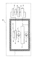
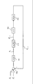
- FIG. 41 is a model diagram of the vibration damping device 910 using the auxiliary mass 300.
- the housing 1 supports the main frame portion 100, the buffer support member 200, the auxiliary mass 300, and the buffer member 350.
- the main frame part 100 is supported by the housing 1 via a buffer support member 200.
- the auxiliary mass 300 is supported by the main frame portion 100 via the buffer member 350.
- the buffer support member 200 is a buffer support part, and the buffer member 350 is a buffer part.
- the main frame unit 100 is a unit including a spindle motor, an information pickup, frames, and the like, and the total mass thereof is mass m 1 .
- the spindle motor has a function of rotating the disk.
- the information pickup has a function of recording information on the disc or reading information on the disc.
- the frames have a function of holding a spindle motor and an information pickup.
- the main frame portion 100 is supported by the housing 1 via a buffer support member 200.
- the buffer support member 200 has a function of buffering transmission of external vibration acting on the housing 1 to the main frame unit 100.
- the auxiliary mass 300 is supported by the main frame portion 100 via the buffer member 350.
- the buffer member 350 has a physical property value that provides resonance characteristics described later.
- the force F 0 [N] is a force that is generated based on external vibration and is transmitted from the housing 1 to the main frame portion 100 via the buffer support member 200.
- the force F 1 [N] is a force generated based on the rotation of the eccentric gravity center disk.
- the transmission force F 1 — 2 [N] is a force that is transmitted from the main frame unit 100 to the auxiliary mass 300 via the buffer member 350.
- FIG. 42 is a diagram expressing FIG. 41 as a mass system model.
- the main frame portion 100 is represented by mass m 1 [kg].
- the buffer support member 200 is represented by a viscoelastic model.
- the elastic coefficient of the spring 200a of the buffer support member 200 is k 1 [N / m]
- the viscosity coefficient of the oil damper 200b of the buffer support member 200 is c 1 [N ⁇ s / m].
- the auxiliary mass 300 is expressed by mass m 2 [kg].
- the buffer member 350 is represented by a viscoelastic model.
- the elastic coefficient of the spring 350a of the buffer member 350 is k 2 [N / m]
- the viscosity coefficient of the oil damper 350b of the buffer member 350 is c 2 [N ⁇ s / m].
- Position x 1 [m] indicates the position of the vibration direction of the mass point m 1 of the housing 1 as a reference when you define the main frame portion 100 as the mass point m 1.
- Position x 2 [m] indicates the position of the vibration direction of the mass point m 2 with reference to the casing 1 in the case of defining the auxiliary mass 300 as the mass point m 2.
- the housing 1 is defined as GND.
- the force F 0 [N] is defined as a force acting on the main frame portion 100 via the buffer support member 200.
- the force F 1 [N] is a force acting on the main frame portion 100 based on the rotation of the eccentric gravity center disk.
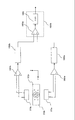
- FIG. 43 is a block diagram representing the above two equations of motion (1) and (2).
- a functional block 110 is a basic model of the main frame unit 100 resonance system.
- the functional block 110 is expressed by an adder / subtractor 700b, an adder 700c, a functional block 100a, integrators 701a and 701b, a functional block 200a, and a functional block 200b.
- the functional block 100a is represented by the reciprocal of the mass m 1 of the main frame part 100.
- the functional block 200 a is represented by the elastic coefficient k 1 of the buffer support member 200.
- Function block 200b is expressed by the viscosity coefficient c 1 of the shock supporting member 200.
- the value of the force F 0 and the value of the force F 1 are added by the adder / subtractor 700a, the value of the transmission force F 2_1 is subtracted, and then output to the adder / subtractor 700b.
- the value of the transmission force F 2_1 is output from the function block 310.
- the function block 310 is a transfer characteristic model of the resonance system of the auxiliary mass 300.
- the force F 1 — 2 is the sum of forces transmitted from the main frame unit 100 to the auxiliary mass 300.
- the force F 2_1 is a force transmitted from the auxiliary mass 300 to the main frame unit 100. That is, the force F 2_1 is the total sum of the damping forces with respect to the main frame portion mass 100.
- the adder 700c adds the value of the value of the position x 1 and x 1 k, the value of the speed d (x 1) / dt of the main frame portion 100 to 1 ⁇ c.
- Position x 1 indicates the position of the mass point m 1 with reference to the casing 1 in the case of defining the main frame portion 100 as the mass point m 1.
- the adder / subtractor 700b adds the output value of the adder 700c and the output value of the adder / subtractor 700a.
- the output value of the adder / subtractor 700b is multiplied by 1 / m 1 in the function block 100a and output to the integrator 701a.
- the functional block 100a is represented by the reciprocal of the mass m 1 of the main frame part 100.
- the integrator 701a integrates the input value and outputs a speed d (x 1 ) / dt.
- the speed d (x 1 ) / dt is input to the integrator 701b, and the value of the position x 1 is output.
- Position x 1 indicates the position of the mass point m 1 with reference to the casing 1 in the case of defining the main frame portion 100 as the mass point m 1.
- the functional block 210 converts the position and speed of the main frame unit 100 into a force that is transmitted to the auxiliary mass 300.
- the functional block 210 is expressed by an adder 700d, a functional block 350a, and a functional block 350b.
- the functional block 350 a is represented by the elastic coefficient k 2 of the buffer member 350.
- Function block 350b is expressed by the viscosity coefficient c 2 of the cushioning member 350.
- the adder 700d adds the value of the value of the position x 1 and 2 times k, the value of the speed d (x 1) / dt of the main frame portion 100 and two times c.
- Position x 1 indicates the position of the mass point m 1 with reference to the casing 1 in the case of defining the main frame portion 100 as the mass point m 1.
- the output value of the adder 700d is output to the adder / subtractor 700e.
- the function block 310 is a transfer characteristic model of the resonance system of the auxiliary mass 300.
- the functional block 310 is expressed by an adder / subtractor 700e, an adder 700f, a functional block 300a, integrators 701c and 701d, a functional block 350a, and a functional block 350b.
- the functional block 300a is represented by the reciprocal of the mass m 2 of the auxiliary mass 300.
- the functional block 350 a is represented by the elastic coefficient k 2 of the buffer member 350.
- Function block 350b is expressed by the viscosity coefficient c 2 of the cushioning member 350.
- the adder 700f adds the value of the value of the position x 2 to 2 times k, and a value that the speed of the auxiliary mass 300 d and (x 2) / dt was doubled c.
- Position x 2 indicates the position of the mass point m 2 with reference to the casing 1 in the case of defining the auxiliary mass 300 as the mass point m 2.
- the output value of the adder 700f is subtracted by the adder / subtractor 700e.
- the output value of the adder 700d is added by the adder / subtractor 700e.
- the output value of the adder / subtractor 700e is multiplied by 1 / m 2 in the function block 300a and output to the integrator 701c.
- the functional block 300a is represented by the reciprocal of the mass m 2 of the auxiliary mass 300.
- the integrator 701c integrates the input value and outputs a speed d (x 2 ) / dt.
- the velocity d (x 2 ) / dt is input to the integrator 701d, and the value of the position x 2 with respect to the housing 1 when the auxiliary mass 300 is defined as the mass point is output.
- Position x 2 indicates the position of the mass point m 2 with reference to the casing 1 in the case of defining the auxiliary mass 300 as the mass point m 2.
- the force F 1_2 and the force F 2_1 are expressed by the following equations (3) and (4).
- the functional block 110 is a basic model of the main frame unit 100 resonance system.
- the functional block 110 is an area surrounded by a broken line including the functional block 100a of FIG.
- the functional block 100a is represented by the reciprocal of the mass m 1 of the main frame part 100.
- the function block 310 is a transfer characteristic model of the resonance system of the auxiliary mass 300.
- the function block 310 is an area surrounded by a broken line including the function block 300a.
- the functional block 300a represents the reciprocal of the mass m 2 of the auxiliary mass 300.
- a functional block 310 represents a transfer characteristic model of a force acting on the main frame unit 100 based on a force applied to the resonance system of the auxiliary mass 300.
- the functional block 210 shows a conversion characteristic in which the buffer member 350 converts the position and speed of the main frame portion 100 into a force that is transmitted to the auxiliary mass 300.
- the output value of the functional block 210 is the value of the transmission force F 1 — 2 [N].
- the transmission force F 1 — 2 [N] is the total sum of the forces transmitted from the function block 110 to the function block 310.
- the functional block 110 is a basic model of the resonance system of the main frame unit 100.
- the function block 310 is a transfer characteristic model of the resonance system of the auxiliary mass 300.
- the transmission force F 2_1 is a force transmitted from the function block 310 to the function block 110.
- the function block 310 is a transfer characteristic model of the resonance system of the auxiliary mass 300.
- the functional block 110 is a basic model of the resonance system of the main frame unit 100.
- FIG. 44 is a block diagram in which FIG. 43 is equivalently converted and displayed as a transfer function. And values of the force F 1 of the force F 0 in subtractor 700a is added, the value of the transmission force F 2_1 is subtracted. The output value of the adder / subtractor 700a is multiplied by 1 / (m 1 s 2 + c 1 s + k 1 ) in the function block 110 to output the value at the position x 1 .
- the functional block 110 is a basic model of the main frame unit 100 resonance system.
- the function block 210 multiplies the value of the position x 1 by (c 2 s + k 2 ) and outputs the value of the transmission force F 1_2 .
- the value at position x 1 is the input value of the function block 210.
- the function block 310 multiplies the value of the transmission force F 1_2 by m 2 s 2 / (m 2 s 2 + c 2 s + k 2 ) and outputs the value of the transmission force F 2_1 .
- the value of the transmission force F 1 — 2 is an input value of the function block 310.
- the function block 310 is a transfer characteristic model of the resonance system of the auxiliary mass 300.
- FIG. 45 is a block diagram in which the transfer characteristic of the functional block 110 is expressed as G 1 (s) and the transfer characteristic of the functional block 310 is expressed as G 2 (s) among the functional blocks shown in FIG.
- the functional block 110 is a basic model of the main frame unit 100 resonance system.
- the functional block 310 is a basic model of the resonance system of the auxiliary mass 300.
- the transfer characteristics G 1 (s) and G 2 (s) are expressed by the following expressions (5) and (6).
- the input signal is multiplied by G 1 (s), and in the functional block 310, the input signal is multiplied by G 2 (s).
- the functional block 110 is a basic model of the main frame unit 100 resonance system.
- the function block 310 is a transfer characteristic model of the resonance system of the auxiliary mass 300.
- the functional block 310 is a basic model of the resonance system of the auxiliary mass 300.
- the transfer characteristic G 2 (s) is the transfer characteristic of the functional block 310. 45 and Expression (6), the transfer characteristic G 2 (s) is a transfer function model in which the input is the value of the transfer force F 1_2 and the output value is the dynamic characteristic of the transfer force F 2_1 . Further, the input of the function block 110 is set to the value of the force Ftotal .
- the functional block 110 is a basic model of the resonance system of the main frame unit 100.
- the transfer characteristic G 1 (s) is a transfer characteristic of the functional block 110. This force F total is expressed by the following equation (7).
- the transmission force F 2_1 is a vibration damping force for the main frame unit 100.
- the functional block 110 is a basic model of the resonance system of the main frame unit 100. Reconsidering FIG. 45, the functional block 110 adds the auxiliary mass 300 so that the transmission force F 2_1 as the damping force functions in response to the application of the value of the force F 0 and the value of the force F 1. Represents. That is, the functional block 110 represents that the vibration of the main frame 100 can be suppressed by adding the auxiliary mass 300. Therefore, in order to improve the vibration damping performance, it is necessary to set at least the value of the transmission force F 2_1 to be large.
- the functions of the function block 210 and the function block 310 are to reduce the sensitivity of the function block 110 to disturbance in a predetermined frequency band.
- the functional block 310 is a basic model of the resonance system of the auxiliary mass 300.
- the functional block 110 is a basic model of the resonance system of the main frame unit 100.
- the embodiment shown in the present invention are set embodiment to function effectively against the force F 1.
- Force F 1 is a centrifugal force unbalance disk occurs during rotation. As described above, the force F 1 is proportional to the square of the disk rotation speed, and thus becomes maximum at the maximum value of the disk rotation speed. That is, the force F 1 becomes maximum at the maximum disk rotation frequency f max [Hz].
- the functional block 110 is a basic model of the resonance system of the main frame unit 100.
- the functional block 310 is a basic model of the resonance system of the auxiliary mass 300. At this time, the resonance frequency f 0 [Hz] of the functional block 310 is expressed by the following equation (8).
- the resonance frequency f 0 is expressed by the following equation (9).
- viscosity coefficient c 2 is expressed by the following equation (11).
- the functional block 310 is a basic model of the resonance system of the auxiliary mass 300.
- the Q value is a dimensionless amount given by the resonance frequency displacement amplitude ratio with respect to the displacement under static load.
- the transfer characteristic G 2 (s) is a function having the disk maximum rotation frequency f max and the Q value Q 2 as parameters.
- Q 2 is the Q value of the basic model of the resonance system of the auxiliary mass 300. It can be seen that the transfer characteristic G 2 (s) is uniquely determined only by these two parameters.
- the maximum rotation frequency f max is a parameter that determines the resonance frequency of the transfer characteristic G 2 (s). Since f max is the maximum rotation frequency of the disk, it is a constant set by the specifications of the apparatus. Therefore, f max is a characteristic that does not depend on the mass m 2 of the auxiliary mass 300 resonance system.
- the transmission force F 2_1 functions as a vibration damping force. Therefore, in order to increase the effect of the resonance system of the auxiliary mass 300, it is necessary to increase the transmission force F 2_1 .
- the characteristic of the transfer characteristic G 2 (s) does not improve even if the mass m 2 of the auxiliary mass 300 is greatly changed.
- the value of the transmission force F 1_2 is an input signal of the transmission characteristic G 2 (s). Therefore, in order to greatly improve the vibration damping effect of the resonance system of the auxiliary mass 300, it can be understood that the value of the transmission force F1_2 must be set large.
- the value of the transmission force F 1_2 is an input signal of the transmission characteristic G 2 (s).
- the definition of the transmission force F 1 — 2 is as shown in Expression (3). That is, the transmission force F 1_2 is defined as the sum of the value of the position x 1 multiplied by k 2 and the speed multiplied by c 2 .
- Position x 1 indicates the position of the mass point m 1 with reference to the casing 1 in the case of defining the main frame portion 100 as the mass point m 1. Substituting Equation (10) and Equation (12) into Equation (3), the following Equation (14) is obtained.
- FIG. 46 is a block diagram when FIG. 45 is converted by equation (14). Therefore, as shown in FIG. 46, the value of the position x 1 is multiplied by m 2 H (s) in the function block 210 and is output as the value of the transmission force F 1_2 .
- the position x 1 is a relative position between the housing 1 and the main frame unit 100.
- the transmission force F 1_2 is the product of the mass m 2 of the auxiliary mass 300 and H (s).
- H (s) uses the maximum disk rotation frequency f max and the Q value Q 2 as parameters. That is, H (s) is a function that does not depend on the mass m 2 of the auxiliary mass 300.
- Q 2 is the Q value of the basic model of the resonance system of the auxiliary mass 300. Accordingly, the transmission force F 1 — 2 is expressed by an amount proportional to the mass m 2 of the auxiliary mass 300 from the equation (14). That is, in order to obtain a large vibration damping effect, at least the mass m 2 of the auxiliary mass 300 needs to be set large.
- the above formulas have been described, but the above validity is confirmed by analysis.
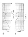
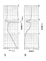
- FIG. 47 is a diagram illustrating an analysis result of frequency characteristics of acceleration of the main frame unit 100 with respect to the force F 1 [N].
- the horizontal axis is frequency [Hz]
- the vertical axis is gain [dB].
- the horizontal axis represents frequency [Hz]
- the vertical axis represents phase [degree].
- a curve D1 indicates a characteristic when the auxiliary mass 100 has no resonance system
- a curve D2 indicates a characteristic when the auxiliary mass 100 has a resonance system.
- the force F 1 [N] is a disturbance input.
- the mass m 1 of the main frame 100 is 85 [g]
- the elastic modulus k 1 is 168000 [N / m]
- the viscosity coefficient c 1 is 11.74 [N ⁇ s / m]
- the mass of the auxiliary mass 300 m 2 is 50 [g]
- the peak value of the resonance amplitude with respect to the resonance frequency f 0 is 20 [dB]
- the maximum disk rotation frequency f max is 65 [Hz].
- f 0 is the resonance frequency of the basic model of the resonance system of the auxiliary mass 300.
- the vertical axis in FIG. 47 indicates the gain, and the horizontal axis in FIG. 47 indicates the frequency.
- the gain on the vertical axis indicates the sensitivity characteristic of “acceleration of the main frame unit 100” with respect to “external force applied to the main frame unit 100”.
- the lower the gain the lower the sensitivity to external force. That is, the lower the gain, the smaller the acceleration of the main frame unit 100 with respect to the external force, which is preferable for the apparatus.
- the force F 1 is a force generated based on the rotation of the eccentric gravity center disk. Both are compared at the maximum disk rotation frequency f max [Hz] at which the force F 1 is maximum.
- the gain when there is no resonance system of the auxiliary mass 300 is about 22 dB. When there is a resonance system of the auxiliary mass 300, it is about 5 dB. That is, the sensitivity of about 17 dB is improved with respect to the force caused by the disturbance.
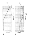
- FIG. 48 shows characteristics when the value of the mass m 2 of the auxiliary mass 300 is set to 1/5 and 5 times the set value of FIG. 47 under the same setting conditions as FIG.
- the horizontal axis is frequency [Hz]
- the vertical axis is gain [dB].
- the horizontal axis is the frequency [Hz]
- the vertical axis is the phase [degree].
- the curve E1 shows the characteristic when the mass m 2 is not changed
- the curve E2 shows the characteristic when the mass m 2 is set to 1/5
- the curve E3 shows the mass m 2 increased five times.
- the characteristics when set are shown.
- the characteristics of FIG. 47 are also shown.
- the present invention has been made to solve the above-described problems.
- the transmission force F 1_2 is proportional to the mass m 2 of the auxiliary mass 300
- set large mass m 2 of the auxiliary mass 300 and to set a large transmission force F 1_2 To do is equivalent. Therefore, detecting the value of the transmission force F 1 — 2 , amplifying the detection signal, and applying it to the mass m 2 of the auxiliary mass 300 in the force dimension is equivalent to setting the mass m 2 of the auxiliary mass 300 large. It becomes.
- amplifying the value of the transmission force F 1 — 2 and applying it to the mass m 2 of the auxiliary mass 300 can provide the same damping effect as when the mass m 2 of the auxiliary mass 300 is increased. This will be reviewed below using a block diagram.
- Figure 49 is Figure 46, the function of detecting the value of the transmission force F 1_2, and the detection result of the value of the transmission force F 1_2 alpha multiplying the ability to apply the dimension of force to the mass m 2 of the auxiliary mass 300 It is the block diagram which added.
- the functional block 501 amplifies the value of the detected transmission force F 1_2 .
- the amplification coefficient of the functional block 501 is ⁇ .
- FIG. 50 is obtained.
- the value of the transmission force F 1 — 2 is an input value of the function block 502.
- Function block 502 outputs the value of the transmission force F 1_2 ( ⁇ + 1) multiplied by.
- Figure 50 detects the value of the transmission force F 1_2, applying the mass m 2 of the auxiliary mass 300 the dimension of force amplifies the detection signal in the amplification coefficient ⁇ is, the mass m 2 of the auxiliary mass 300 It is equivalent to having multiplied ( ⁇ + 1) times.
- the amplification coefficient ⁇ can be set to an arbitrary value. Therefore, if the amplification coefficient ⁇ is set to a large value, a large damping effect can be obtained regardless of the value of the mass m 2 of the auxiliary mass 300.
- the analysis result shown in FIG. 51 shows that the value of the transmission force F 1 — 2 is detected under the same setting conditions as in FIG. 47, and this detection signal is amplified by the amplification coefficient ⁇ to obtain the mass m 2 of the auxiliary mass 300 in the force dimension.
- the condition to apply is added.
- the horizontal axis represents frequency [Hz] and the vertical axis represents gain [dB].
- the horizontal axis represents frequency [Hz] and the vertical axis represents phase [degree].
- a curve B4 is a curve in which the amplification coefficient ⁇ is set to ⁇ 0.8.
- the value of the amplification coefficient ⁇ is set to ⁇ 0.8, zero, and 4.
- the value of the amplification coefficient ⁇ was set so that the values multiplied by ( ⁇ + 1) were equal to 0.2, 1 and 5, and the magnification of the mass m 2 of the auxiliary mass 300 in FIG. That is, when the amplification coefficient ⁇ is ⁇ 0.8, the mass m 2 of the auxiliary mass 300 is 0.2 times, and when the amplification coefficient ⁇ is zero, the mass m 2 of the auxiliary mass 300 is 1 time.
- the auxiliary mass 300 is set to correspond to the case where the mass m 2 of the auxiliary mass 300 is 5 times. 47 and 51 are compared, the characteristic in which the mass m 2 of the auxiliary mass 300 in FIG.
- the characteristic of the auxiliary mass 300 without change in the mass m 2 in FIG. 47 is naturally the same as the characteristic in which the amplification coefficient ⁇ in FIG. 51 is set to zero.
- the characteristic in which the mass m 2 of the auxiliary mass 300 in FIG. 47 is set to 5 times is exactly the same as the characteristic in which the amplification coefficient ⁇ in FIG. 51 is set to 4.
- the disk device has a vibration source.
- the vibration source is the unnecessary centrifugal force F 1 generated by the rotation of the eccentric gravity center disk on the main frame portion 100.
- the centrifugal force F 1 is proportional to the square of the disk rotation speed. Therefore, the centrifugal force F 1 becomes the maximum value when the disc speed becomes highest. Therefore, the disk device needs a function of effectively suppressing unnecessary centrifugal force F 1 generated at the maximum rotation frequency of the disk.
- an information pickup detects a signal with a constant track linear velocity. For this reason, the rotational speed is small on the outer periphery of the disk, and the rotational speed is large on the inner periphery. Since the centrifugal force F 1 is proportional to the square of the disk rotation speed, an information pickup tracking error occurs when a signal on the inner circumference of the disk is read or a signal is written on the inner circumference of the disk. In other words, the tracking error of the information pickup occurs less frequently except for the inner circumference of the disk, and does not cause a problem. Therefore, an object of the present invention is to reduce tracking errors of information pickup on the inner circumference of the disc.
- Dynamic vibration absorbers are conventionally known as a mechanistic measure against disturbance vibrations in a specific frequency band.
- the vibration damping effect of the dynamic vibration absorber is highest when the resonance frequency of the dynamic vibration absorber is set to a frequency at which it is desired to be suppressed.
- the frequency to be suppressed is the maximum rotation frequency of the disk.
- the vibration damping performance is proportional to the size of the auxiliary mass 300. Therefore, the apparatus using the dynamic vibration absorber needs to set the auxiliary mass 300 large in order to obtain a large vibration damping effect.
- An active dynamic vibration absorber is a device in which a controller and an actuator are added to the dynamic vibration absorber to improve vibration damping performance. That is, the active dynamic vibration absorber is a vibration damping device that actively drives the auxiliary mass 300 of the dynamic vibration absorber. By driving the auxiliary mass 300 with a signal equivalent to the large auxiliary mass 300, the active dynamic vibration absorber can obtain a large vibration damping effect with the small auxiliary mass 300.
- the signal for driving the auxiliary mass 300 is a signal obtained by amplifying the value of the transmission force F 1_2 transmitted from the main frame 100 to the auxiliary mass 300.
- Expression (3) indicates that the transmission force F 1_2 is a function obtained by multiplying the relative position x 1 between the main frame 100 and the housing 1 by the frequency characteristic of the resonance system of the dynamic vibration absorber. Therefore, to determine the relative position x 1 of the main frame 100 and the casing 1, obtaining the value of the transmission force F 1_2 by electrically making a filter having a transfer characteristic in parentheses on the right side of formula (3) be able to. If the value of the transmission force F 1 — 2 is amplified and the auxiliary mass 300 is driven, the auxiliary mass 300 becomes equivalent to a large auxiliary mass, and the vibration damping device can obtain a large vibration damping effect. In the embodiment described below, a specific example for obtaining the value of the transmission force F 1 — 2 is shown.
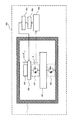
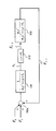
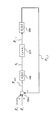
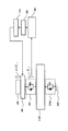
- FIG. 1 is a model diagram of a vibration damping device 900 using the actively operating auxiliary mass 300 shown in the first embodiment.
- the transmission force detection unit 400 has a function of detecting the value of the transmission force F 1_2 .
- the transmission force F 1_2 is a force transmitted from the main frame portion 100 to the auxiliary mass 300.
- the amplifier 500 has a function of amplifying the output value detected by the transmission force detector 400 with an amplification coefficient ⁇ described later.
- the auxiliary mass driving unit 360 is provided in the main frame unit 100 and has a configuration in which the auxiliary mass 300 is connected to the movable unit.
- the auxiliary mass driving unit 360 is driven by the driver 510 based on the output signal of the amplifier 500.
- the amplification factor of the amplifier 500 is determined so that the total gain of the transmission force detection unit 400, the amplifier 500, the driver 510, and the auxiliary mass driving unit 360 becomes the amplification coefficient ⁇ .
- ⁇ ⁇ F 1 — 2 is a force generated by the auxiliary mass driving unit 360 with respect to the auxiliary mass 100.
- FIG. 1 is expressed by function, the auxiliary mass 300, the auxiliary mass driving unit 360, and the buffer member 350 are expressed as separate elements. However, in practice, a part of the fixed part of the auxiliary mass driving part 360 is a part of the main frame part 100. Similarly, the buffer member 350 is an element that connects the movable part and the fixed part of the auxiliary mass driving part 360. The mass of the movable part of the auxiliary mass driving unit 360 is a part of the auxiliary mass 300.
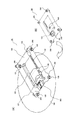
- FIG. 2 is a perspective view showing a specific embodiment for realizing the function of the auxiliary mass driving unit 360.
- FIG. 3 is an exploded perspective view showing the structure of the auxiliary mass driving unit 360 shown in FIG.
- FIG. 6 is a perspective view showing a specific embodiment in which the auxiliary mass driving unit 360 is attached to the main frame unit 100.
- the disk device is manufactured by housing the main frame unit 100 shown in FIG. 6 together with known components such as a power supply and a circuit board in the housing 1.
- the base member 361 of the auxiliary mass driving unit 360 is fixed to the main frame unit 100 (not shown).
- the drive coil 362 is held by two drive coil holding members 363a and 363b.
- the drive coil holding members 363a and 363b are fixed to the base member 361 of the auxiliary mass drive unit 360. Accordingly, the driving coil 362 is positioned and fixed with respect to the base member 361 of the auxiliary mass driving unit 360.
- the drive coil 362 is wired to the wiring terminal 364 of the drive coil 362.
- the wiring terminal 364 is fixed to the driving coil holding member 363a.
- the drive coil 362 is electrically connected to the flexible cable 366 via the flexible cable connector 365.
- a drive signal from the driver 510 is sent to the flexible cable 366.
- the base member 361, the driving coil 362, the driving coil holding members 363a and 363b, the wiring terminal 364, the flexible cable connector 365 and the flexible cable 366, which are already described, are connected and integrated, and there are no movable parts. .
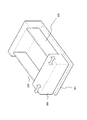
- the permanent magnet 367 is integrally formed with two regions in which the magnetization directions are opposite to each other. In FIG. 3, for the sake of easy understanding, these are distinguished from 367a and 367b.
- the permanent magnet 367 is fixed on the yoke 368a so as to face the yoke 368b.
- the permanent magnet 367 and the yokes 368a and 368b function as a magnetic circuit as a whole.
- an element in which the permanent magnet 367 and the yokes 368a and 368b are integrated is simply referred to as a movable magnetic circuit 390.
- the buffer member 350 shown in FIG. 1 is made of a leaf spring.
- One end of the leaf spring 350 is connected to the movable magnetic circuit 390.
- the other end of the leaf spring 350 is connected to the base member 361 of the auxiliary mass driving unit 360.
- the buffer member 350 made of a leaf spring is fixed to the yoke 368 a and the base member 361 using a coupling screw 369.
- the movable magnetic circuit 390 is supported by the base member 361 of the auxiliary mass driving unit 360 so as to be swingable via two leaf springs (buffer members 350) arranged in parallel. Therefore, as indicated by the white arrow in FIG. 2, the moving direction of the movable magnetic circuit 390 can be moved mainly in the deflection direction of the leaf spring (buffer member 350).
- FIG. 4 is a sectional view of the movable magnetic circuit 390.
- the permanent magnet 367a is magnetized to the south pole on the yoke 368a side and magnetized to the north pole on the yoke 368b side.
- the permanent magnet 367b is magnetized to the north pole on the yoke 368a side and magnetized to the south pole on the yoke 368b side.
- the permanent magnet 367 is fixed on the yoke 368a.
- the permanent magnet 367 is opposed to the yoke 368b through a magnetic gap.
- the driving coil 362 is disposed in the magnetic gap.
- FIG. 5 is an explanatory diagram showing the flow of magnetic flux of the movable magnetic circuit 390 shown in FIG. The arrows in FIG. 5 indicate the flow of magnetic flux.
- a magnetic flux flows from the yoke 368a side to the yoke 368b side in a region (referred to as region A) on the permanent magnet 367a side.
- region A a region on the permanent magnet 367a side.
- region B a region on the permanent magnet 367b side.
- the direction of the magnetic flux is opposite between the region A and the region B.
- the drive coil 362 is disposed in the magnetic gap between the region A and the region B.
- a current flows through the driving coil 362
- a force is generated according to Fleming's left-hand rule.
- the direction is the direction of the arrow in FIG.
- the direction of the arrow is the direction in which the permanent magnet 367a and the permanent magnet 367b are arranged in the left-right direction in FIG.
- a current flows through the driving coil 362 on the permanent magnet 367 a side from the near side to the far side in FIG. 4.
- a current flows from the back side to the front side in FIG.
- the drive coil 362 receives a force on the right side in FIG. Since the driving coil 362 is positioned and fixed to the auxiliary mass driving unit 360, the movable magnetic circuit 390 moves to the left in FIG.
- FIG. 6A is a perspective view of the main frame portion 100 as viewed from the lower surface side.
- FIG. 6B is a perspective view of the main frame portion 100 as viewed from the upper surface side.
- the main frame 120 is positioned and fixed to the casing 1 (not shown) by support columns 128 arranged at the four corners via the buffer support member 200.
- the spindle motor 121 is attached to the main frame 120.
- the spindle motor 121 has a turntable 122 for rotating the disk 129.
- the spindle motor 121 is attached so as to fit into a hole (not shown) provided in the main frame 120.
- the spindle motor 121 is fixed to the main frame 120 by screwing a flange portion provided on the spindle motor 121 to the main frame 120.
- the turntable 122 is disposed on the upper surface side of the main frame 120.
- the turntable 122 is a component on the rotation side of the spindle motor 121.
- a case is disposed on the lower surface side of the main frame 120. The case is a component on the fixed side of the spindle motor 121.
- the information pickup 600 has a function of writing information on the disk 129 or reading information on the disk 129.
- the information pickup 600 is attached to the shaft 123 and the lead screw 124.
- the information pickup 600 can move while being guided by the shaft 123.
- the shaft 123 and the lead screw 124 are attached to the main frame 120.
- a stepping motor 125 is attached to one end of the lead screw 124.
- the stepping motor 125 has a function of rotating the lead screw 124.
- the female screw portion 126 provided in the information pickup 600 meshes with the lead screw 124 that is a male screw. As the lead screw 124 rotates, the information pickup 600 moves in a direction for performing tracking control. The direction in which the tracking control is performed is the radial direction of the disk 129.
- the U-shaped recess 127 provided in the information pickup 600 sandwiches the shaft 123 between the recesses. As a result, the information pickup 600 can move while being guided by the shaft 123.
- the auxiliary mass driving unit 360 is attached to the case.
- the case is a fixed side of the spindle motor 121. This is for directly suppressing the vibration of the spindle motor 121 holding the disk 129.
- the arrow direction shown in FIG. 2 is the radial direction of the disk 129 and is the direction in which the tracking control of the information pickup 600 is performed. This is because the moving direction of the movable magnetic circuit 390 is selected to be the direction in which the tracking control of the information pickup 600 is performed. This is because the force generated by the eccentric gravity center disk adversely affects the direction in which the information pickup 600 performs tracking control.
- the movable magnetic circuit 390 functions as the auxiliary mass 300.
- the auxiliary mass driving unit 360 is a configuration of a general magnetic drive type actuator, so that it can be realized inexpensively and compactly. Further, the auxiliary mass driving unit 360 is not limited to the magnetic driving type as described above. That is, the auxiliary mass driving unit 360 may be driven by a piezoelectric element or other methods.
- the spring member is not limited to a leaf spring, and may be a coil spring or other methods.
- FIG. 7 is a configuration example of the auxiliary mass driving unit 360 using a bimorph element.
- a bimorph element is a piezoelectric transducer that uses two thin piezoelectric elements and expands another piezoelectric element when one piezoelectric element contracts.
- a bimorph 370 connects the auxiliary mass 300 and the base member 361.
- the bimorph 370 also functions as the auxiliary mass driving unit 360 and the buffer member 350. For this reason, this configuration is a simpler configuration and more compact than the magnetic drive type.
- the transmission force F 1_2 is a force transmitted from the main frame portion 100 to the auxiliary mass 300.
- the transmission force detection unit 400 includes a relative position detector and a portion that calculates the value of the transmission force F 1_2 based on a signal detected by the relative position detector.
- the transmission force detection unit 400 detects the value of the transmission force F 1_2 transmitted from the main frame unit 100 to the auxiliary mass 300.
- the relative position detector detects a signal indicating a relative position of the casing 1 and the main frame unit 100 in the vibration direction.
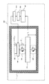
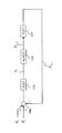
- FIG. 8 is a model diagram of the vibration damping device 901 using the auxiliary mass 300 that actively operates.
- the position x 1 is a relative position between the housing 1 and the main frame unit 100.
- Transmission force detecting portion 401 has a characteristic input signal is the position x 1.
- the transmission force F 1_2 is a force transmitted from the main frame unit 100 to the auxiliary mass 300.
- ⁇ ⁇ F 1 — 2 is a force generated by the auxiliary mass driving unit 360 with respect to the auxiliary mass 100.
- ⁇ is an amplification coefficient.
- Position x 1 is the vibration direction of the relative position of the casing 1 and the main frame portion 100.
- the defining formula of the transmission force F 1 — 2 is as shown in the formula (3).
- the value of the viscosity coefficient c 2 is the coefficient of the first term on the right hand side of (3).
- the mass m 2 of the auxiliary mass 300 is 5 [g], which is one tenth of the value considered in FIG. 47, and the other setting conditions are the same
- the value of the elastic modulus k 2 is equation (16)
- the value of the viscosity coefficient c 2 is the formula (17) follows from the equation (12).
- the mass m 1 of the main frame part 100 is 85 [g]
- the elastic coefficient k 1 is 168000 [N / m]
- the viscosity coefficient c 1 is 11.74 [N ⁇ s / m].
- the peak value of the resonance amplitude with respect to the resonance frequency f 0 is 20 [dB]
- the maximum disk rotation frequency f max is 65 [Hz].
- the resonance frequency f 0 is the resonance frequency of the basic model of the resonance system of the auxiliary mass 300.
- the viscosity coefficient c 2 is smaller than the elastic coefficient k 2 .
- viscosity coefficient c 2 are the coefficients of the speed of the main frame 100 relative to the housing 1.
- s means differentiation
- 1 / s means integration. Therefore, in Expression (3), sx 1 represents a speed obtained by differentiating the value of the position x 1 . Therefore, c 2 is the coefficient of the velocity.
- the definition formula of the transmission force F 1 — 2 shown by the formula (3) is the following formula (18).
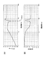
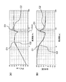
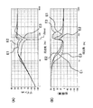
- FIG. 9 is a diagram illustrating detection characteristics of the transmission force F 1_2 with respect to the force F 1 [N].
- the horizontal axis represents frequency [Hz]
- the vertical axis represents gain [dB].
- the horizontal axis represents frequency [Hz]
- the vertical axis represents phase [degree].
- a curve A1 shows the detection characteristic of the value of the transmission force F1_2 in the ideal state.
- Curve A2 shows the detection characteristics of the value of the transmission force F 1_2 based on the value of the position x 1.
- the transmission force F 1_2 is a force transmitted from the main frame portion 100 to the auxiliary mass 300. In FIG. 9, two cases are plotted.
- One example is a characteristic in an ideal state assuming that the detection characteristic of the transmission force detection unit 401 can be accurately detected without error over the entire band. Another case is to ignore the viscosity coefficient c 2 with the setting conditions of the first embodiment, the detection value of the transmission force F 1_2 only by a relative value of the position x 1 of the casing 1 and the main frame portion 100 It is a characteristic. That is, the detection characteristic of the value of the transmission force F 1_2 based on the equation (18).
- the detection characteristic of the value of the transmission force F 1 — 2 is macroscopically a secondary low-pass characteristic.
- the cutoff frequency is a resonance frequency of a resonance system composed of the main frame portion 100 and the buffer support member 200.
- the influence of the resonance system composed of the auxiliary mass 300 and the buffer member 350 can be confirmed at the disk maximum rotation frequency f max [Hz]. Comparing the characteristic in the ideal state with the detection characteristic based on the equation (18), the characteristic in the ideal state is slightly advanced in phase with respect to the detection characteristic based on the equation (18) at a high frequency of 100 Hz or higher. It has become.
- the transmission force F 1_2 follows the formula (3), and therefore, the relative position x 1 between the housing 1 and the main frame portion 100 is dominant in the low frequency range.
- the relative speed d (x 1 ) / dt between the casing 1 and the main frame unit 100 is dominant in the high frequency range. Accordingly, in the high frequency range, the detection characteristic of the value of the transmission force F 1 — 2 becomes a leading characteristic. It is confirmed that the detection characteristic in the ideal state and the detection characteristic based on the expression (18) in the first embodiment are substantially the same in the band below the disk maximum rotation frequency f max [Hz] that is the band to be controlled. it can.
- FIG. 10 is a diagram illustrating an analysis result of frequency characteristics of acceleration of the main frame unit 100 with respect to the force F 1 [N].
- the horizontal axis represents frequency [Hz] and the vertical axis represents gain [dB].
- the horizontal axis is frequency [Hz]
- the vertical axis is phase [degree].
- the detection characteristic is a characteristic based on the equation (18) of the present embodiment shown in FIG. 9, and the value of the amplification coefficient ⁇ is set to 9.
- the characteristic of FIG. 10 is a characteristic when the value of the auxiliary mass 300 is 5 [g].
- the characteristic of FIG. 10 is the same as that of FIG. 47, despite the small value of 1/10 (5 [g]) of the conventional auxiliary mass 300.
- the characteristic is equivalent to the characteristic.
- the characteristics shown in FIG. 47 are those of the conventional auxiliary mass 300 only.
- the gain of the maximum disk rotation frequency f max [Hz] is substantially equal to that shown in FIG. That is, the vibration damping device 901 can obtain a large vibration damping effect even when the small and light auxiliary mass 300 is used.
- the disk maximum rotation frequency f max [Hz] is a frequency at which the disturbance acceleration due to the eccentric gravity center of the disk is maximized.
- FIG. 11 is a diagram showing a specific example of a function of the relative position detector for detecting the value of the position x 1.
- the position x 1 is a relative position in the vibration direction between the housing 1 and the main frame unit 100.
- a coordinate diagram is shown in the lower right of FIG.
- the x-axis direction is the tangential direction of the disk
- the y-axis direction is the radial direction of the disk
- the z-axis direction is the focus direction of the disk (perpendicular to the disk surface).
- This relative position detector has a function of detecting the relative position of the housing 1 and the main frame portion 100 in the radial direction of the disk (the y-axis direction in FIG. 10).
- the relative position detector has no sensitivity with respect to the movement of the z-axis direction component of the main frame unit 100.
- the radial direction of the disc is the tracking control direction of the information pickup 600.
- the permanent magnet 372 is positioned and fixed to the magnet holder 371.
- the magnet holder 371 is positioned and fixed to the main frame portion 100. That is, the permanent magnet 372 is positioned and fixed with respect to the main frame portion 100.
- the hall elements 373a and 373b are positioned and held by a hall element holding member 374 made of a circuit board or the like.
- the hall element holding member 374 is positioned and fixed to the housing 1. That is, the Hall elements 373a and 373b are positioned and fixed with respect to the housing 1.
- the permanent magnet 372 is positioned and fixed to the main frame portion 100.
- the hall elements 373a and 373b are positioned and fixed to the housing 1.
- the relative position detector is configured to detect the movement amount of the permanent magnet 372 as a change in magnetic flux density using the Hall elements 373a and 373b.
- the permanent magnet 372 is magnetized in the x-axis direction and has a characteristic in which the magnetization direction is reversed at the center position in the y-axis direction.
- the permanent magnet 372 is integrally formed, in FIG. 10, in order to facilitate understanding, the difference in the magnetization direction is distinguished as 372a and 372b.
- the hall elements 373a and 373b are arranged at positions in the y-axis direction where the magnetization direction of the permanent magnet 372 is switched.
- the permanent magnet 372 and the hall element 373a will be described as an example in order to explain the change in output of the hall element with respect to the positional relationship between the permanent magnet and the hall element.
- the permanent magnet 372 and the hall element 373a are arranged to face each other in the x-axis direction with a certain gap.
- the center of the Hall element 373a is located at the y-axis position where the magnetization direction of the permanent magnet 372 switches.
- the strength of the magnetic flux at the position of the hall element 373a corresponds to the change in the position of the hall element 373a with respect to the permanent magnet 372. It changes almost linearly. For this reason, the output value of the Hall element 373a changes linearly.
- the Hall element 373a is not sensitive to the movement of the z-axis direction component of the permanent magnet 372, and the output value of the Hall element 373a does not change.
- the magnetic flux detection output value of the Hall element 373a can be treated as the displacement of the y-axis direction component of the permanent magnet 372. Further, the Hall element 373a has no sensitivity with respect to the displacement of the z-axis direction component.
- the z-axis direction is the focus direction of the information pickup.
- the relative position detector arranges a pair of Hall elements 373a and 373b facing each other at a predetermined interval as shown in FIG. A permanent magnet 372 is inserted between the hall element 373a and the hall element 373b.
- the relative distance between the hall element 373a and the permanent magnet 372 in the x-axis direction component becomes small, so the detection sensitivity of the y-axis direction component increases. To do.
- the detection sensitivity of the y-axis direction component decreases. Therefore, by taking the average of the detection output values of the Hall elements 373a and 373b, fluctuations in detection sensitivity due to a change in the x-axis direction component of the permanent magnet 372 can be almost nullified.
- the average of the detection output values of the Hall elements 373a and 373b can be easily realized by, for example, a method of adding both detection signals by half.
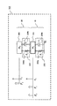
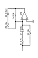
- FIG. 12 is a block diagram showing a circuit configuration of the relative position detector.
- the two terminals of the Hall element 373a one negative output is connected to the negative side of the input terminal of the differential amplifier 1001a, and the other positive output is connected to the positive side of the input terminal of the differential amplifier 1001a.
- the output terminal of the differential amplifier 1001a is connected to the DC component removal filter 1002a.
- one positive output is connected to the negative side of the input terminal of the differential amplifier 1001b, and the other negative output is connected to the positive side of the input terminal of the differential amplifier 1001b.
- the output terminal of the differential amplifier 1001b is connected to the DC component removal filter 1002b.
- the signal detected by the Hall element 373a is output to the DC component removal filter 1002a.
- the signal detected by the Hall element 373b is output to the DC component removal filter 1002b.
- the DC component removal filters 373a and 373b are used to remove the offset of the DC component because the offset of the DC component is an adverse effect of the control.
- the other terminals of the DC component removal filters 1002a and 1002b are connected to the input terminal of the addition amplifier 1003a.
- the output terminal of the addition amplifier 1003a is connected to the attenuator 1003.
- the summing amplifier 1003a and the attenuator 1003 constitute an averaging circuit 1003b.
- the attenuator 1003 outputs a value obtained by multiplying the input value by 0.5 as a displacement signal of the y-axis direction component of the permanent magnet 372.
- FIG. 13 is a characteristic diagram showing the output characteristics of the relative position detector.
- the horizontal axis is the position of the y-axis direction component of the Hall element, and the vertical axis is the output value of the Hall element.
- the alternate long and short dash line (1) indicates that the distance between the Hall element and the permanent magnet is 1 mm
- the small broken line (2) indicates that the distance between the Hall element and the permanent magnet is 1.5 mm
- the large broken line (3) indicates that the Hall element and the permanent magnet are permanent.
- the distance to the magnet is 2 mm.
- a value obtained by averaging the one-dot chain line (1) and the large broken line (3) is indicated by a solid line.
- the solid line shows a value almost equivalent to the small broken line (2) in which the distance between the Hall element and the permanent magnet is 1.5 mm. From this, it can be seen that the relative position detector can substantially invalidate fluctuations in detection sensitivity based on the displacement of the x-axis direction component of the permanent magnet.
- the solid line shows the average value of the alternate long and short dash line (1) and the large broken line (3).
- the relative position detector can detect a change in the relative position of only the one-axis direction component (y-axis direction component in this example) between the casing 1 and the main frame unit 100. Since the permanent magnet 372 and the Hall elements 373a and 373b are inexpensive elements, the relative position detector of the present detection system is inexpensive and can realize high performance characteristics.
- the relative position detector using the pair of Hall elements 373a and 373b and the permanent magnet 372 can be widely used as a detector for detecting the relative position displacement amount of the uniaxial component. That is, in the first embodiment, the relative position detector using the pair of Hall elements 373a and 373b and the permanent magnet 372 is used to detect the relative position between the housing 1 and the main frame unit 100. It can also be used to detect the relative position of the main frame part 100 and the auxiliary mass 300.
- the vibration damping devices 900 and 901 include the auxiliary mass 300 in the main frame portion 100 via the buffer member 350.
- the transmission force detection unit 400 of the vibration damping device 900 detects the value of the transmission force F 1_2 from the main frame unit 100 to the auxiliary mass 300.
- the transmission force detector 400 outputs the value of the transmission force F 1_2 to the amplifier 500.
- the amplifier 500 amplifies the value of the transmission force F 1 — 2 and outputs it to the driver 510.
- the driver 510 drives the auxiliary mass driving unit 360 to give the auxiliary mass 300 a force obtained by amplifying the value of the transmission force F 1_2 . Accordingly, the vibration damping device 900 can obtain a vibration damping effect equivalent to that of the large auxiliary mass 300 with the small auxiliary mass 300.
- transmission force detecting portion 401 of the vibration damping device 901 detects the value of the position x 1.
- the position x 1 is a relative position in the vibration direction between the housing 1 and the main frame unit 100.
- the transmission force F 1_2 is obtained by adding the elastic coefficient k 1 of the buffer member 350 to the value of the position x 1 .
- the value of the transmission force F 1 — 2 is amplified with the amplification coefficient ⁇ by the amplifier 500 and output to the driver 510.
- the driver 510 drives the auxiliary mass driving unit 360 to apply a force ⁇ F 1_2 to the auxiliary mass 300.
- Position x 1 is the vibration direction of the relative position of the casing 1 and the main frame portion 100.
- the relative position detector detects the value of the relative position x 1 in the vibration direction between the housing 1 and the main frame unit 100.
- a pair of Hall elements 373a and 373b are arranged in parallel to face each other.
- the permanent magnet 372 is disposed between the pair of Hall elements 373a and 373b.
- the relative position detector has no sensitivity with respect to the displacement of the focus direction component.
- the relative position detector can detect only the displacement signal of the radial direction component of the disk 129 by canceling the signal of the tangential direction component of the disk 129.
- the auxiliary mass driving unit 360 shown in FIGS. 2 and 3 is damaged by repeated bending of the coil wire because the wiring of the driving coil 362 is attached to the fixed driving coil holding member 363a. You can avoid doing that.
- the relative position detector shown in FIG. 11 can also be damaged by repeatedly bending the wire used for wiring by attaching the Hall element holding member that holds the Hall element 373 to the housing 1 on the fixed side. Can be avoided.
- the transmission force detection units 400 and 401 are small in size with a simple configuration while having high detection accuracy.
- the auxiliary mass driving unit 360 drives the small and light auxiliary mass 300 based on the detection signals detected by the transmission force detecting units 400 and 401.
- the vibration damping devices 900 and 901 can realize low vibration, small size and light weight, and high vibration damping performance.
- FIG. The transmission force detection unit 401 according to Embodiment 1 obtains the value of the transmission force F 1 — 2 from the value of the relative position x 1 between the housing 1 and the main frame unit 100.
- the transmission force detection unit 402 according to the second embodiment is based on two signals: a value of the relative position (x 2 ⁇ x 1 ) between the auxiliary mass 300 and the main frame unit 100 and a drive signal of the auxiliary mass drive unit 360. It is assumed that the value of the transmission force F 1_2 is estimated.
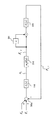
- FIG. 14 is a model diagram of the vibration damping device 902 using the auxiliary mass 300 that actively operates according to the second embodiment. 14, the same components as those of the vibration damping devices 900 and 901 described in FIGS. 1 and 8 are denoted by the same reference numerals, and the description thereof is omitted.
- the position x 1 is a relative position between the housing 1 and the main frame unit 100.
- the position x 2 is a relative position between the housing 1 and the auxiliary mass 300.
- the transmission force F 1_2 is a force transmitted from the main frame unit 100 to the auxiliary mass 300.
- ⁇ ⁇ F 1 — 2 is a force generated by the auxiliary mass driving unit 360 with respect to the auxiliary mass 100.
- ⁇ is an amplification coefficient.
- the position (x 2 ⁇ x 1 ) is a relative position in the vibration direction between the main frame unit 100 and the auxiliary mass 300.
- the input signal of the transmission force detection unit 402 is two signals: a relative position signal between the main frame unit 100 and the auxiliary mass 300 and a driving signal of the auxiliary mass driving unit 360.
- FIG. 15 is a diagram obtained by converting FIG. 14 as a mass point model.
- the auxiliary mass resonance system 30 includes an auxiliary mass 300 and a buffer member 350.
- the main frame part resonance system 10 includes a main frame part 100 and a buffer support member 200.
- the same components as those of the vibration damping device 910 described in FIG. 42 are denoted by the same reference numerals and description thereof is omitted.
- the force F 0 [N] is a force caused by a disturbance acting on the main frame portion 100 based on external vibration.
- the force F 1 [N] is a force due to a disturbance based on the rotation of the eccentric gravity center disk.
- the force F 2 [N] is a force generated by the auxiliary mass driving unit 360.
- the definition of the force F 2 is a correction amount generated by the auxiliary mass driving unit 360. Therefore, the value of the force F 2 corresponds to the output value of the functional block 501 that amplifies the value of the detected transmission force F 1 — 2 in FIG. 49, and the definition thereof is given by the following equation (19).
- FIG. 15 is a block diagram when FIG. 15 is expressed.
- FIG. 16 differs from FIG. 43 in that the value of the force F 2 is added to the adder / subtractor 700 e as an input value of the functional block 310.
- the force F 2 is a force applied to actively perform the correction operation of the auxiliary mass 300.
- the function block 310 is a transfer characteristic model of the resonance system of the auxiliary mass 300.
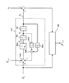
- FIG. 17 is a block diagram when the part of the functional block 310 of FIG. 16 is extracted and the main frame unit 100 is virtually grounded.
- the transmission force detector 402 is a disturbance estimator.
- the function block 310 is a transfer characteristic model of the resonance system of the auxiliary mass 300.
- the transmission force detector 402 is a disturbance estimator. Transmission force detecting portion 402, and outputs the estimated value F'1_2 value of the input to the transmission force F 1_2 the values of the position of the force F 2 (x 2 -x 1) .
- the force F 2 is a correction amount of the auxiliary mass driving portion 360 is generated.
- the function block 310 is a transfer characteristic model of the resonance system of the auxiliary mass 300.
- the position (x 2 ⁇ x 1 ) is a relative position in the vibration direction between the main frame unit 100 and the auxiliary mass 300 and is an output value of the function block 310.
- a control signal driver 510 output is defined as the force F 2
- transmission force F 1_2 is defined as a disturbance.
- the function block 310 is a transfer characteristic model of the resonance system of the auxiliary mass 300.
- the force F 2 is a correction amount generated by the auxiliary mass driving unit 360.
- the transmission force F 1 — 2 is a force that is transmitted from the main frame unit 100 to the auxiliary mass 300 via the buffer member 350.
- the functional block 310 is a general resonance system with one degree of freedom. If this one-degree-of-freedom resonance system is a control target, the value of the transmission force F 1_2 is estimated by calculating a control signal supplied to the control target and a position signal that is a state quantity of the control target.
- the transmission force F 1_2 is a disturbance applied to the controlled object. This mechanism is generally called a disturbance estimator.
- the function block 310 is a transfer characteristic model of the resonance system of the auxiliary mass 300.
- control signals there are two control signals.
- One of the control signals is a value of the force F 2 as a correction amount generated by the auxiliary mass driving unit 360.
- Another control signal is a value of the relative position (x 2 ⁇ x 1 ) of the auxiliary mass 300 and the main frame portion 100 in the vibration direction.
- the transmission force detector estimates the disturbance based on these two control signals.
- the disturbance is a transmission force F1_2 .
- a transmission force detector 402 which is a disturbance estimator, estimates and outputs the value of the transmission force F1_2 .
- Transmission force detecting portion 402 by the detection value the value of the transmission force F 1_2 outputted as the estimated value F'1_2, it is possible to realize the function of detecting the value of the transmission force F 1_2.
- the disturbance estimator Since the disturbance estimator is a known concept, its description is omitted here. There are two types of disturbance estimators, the same dimension type and the minimum dimension type, and either one may be selected. Here, the minimum dimension type with a light calculation load is assumed.
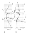
- FIG. 18 shows a detection characteristic of the transmission force F 1_2 with respect to the force F 1 [N].
- the horizontal axis represents frequency [Hz]
- the vertical axis represents gain [dB].
- the horizontal axis represents frequency [Hz]
- the vertical axis represents phase [degree].
- a curve A1 shows the detection characteristic of the value of the transmission force F1_2 in the ideal state.
- a curve A3 shows the detection characteristic of the value of the transmission force F1_2 based on the estimated value of the disturbance estimator.
- the force F 1 [N] is a disturbance input.
- the transmission force detection unit 402 is realized by a minimum dimensional disturbance estimator.
- the pole arrangement of the minimum dimension type disturbance estimator was set to the second-order Butterworth pole with a bandwidth of 1 kHz.
- FIG. 18 two cases are plotted.
- One example is a characteristic in an ideal state on the assumption that the detection characteristic of the transmission force detection unit 402 can be accurately detected without error in the entire band.
- Another example is the detection characteristic of the value of the transmission force F 1 — 2 based on the second embodiment.
- the characteristics in the ideal state are compared with the detection characteristics in the second embodiment.
- the characteristics in the ideal state are slightly advanced in phase with respect to the detection characteristics of the second embodiment at a high frequency of about 100 Hz or higher. However, it can be confirmed that the characteristics are substantially the same in the band below the maximum disk rotation frequency f max [Hz].
- a band below the maximum disk rotation frequency f max [Hz] is a band to be controlled.
- FIG. 19 shows the analysis result of the frequency characteristics of the acceleration of the main frame unit 100 with respect to the force F 1 [N].
- the horizontal axis is frequency [Hz]
- the vertical axis is gain [dB].
- the horizontal axis represents frequency [Hz]
- the vertical axis represents phase [degree].
- the detection characteristic of the transmission force detection unit 402 is a characteristic based on the second embodiment of FIG. 18, and the value of the amplification coefficient ⁇ of the amplifier 500 is set to 9.
- the force F 1 [N] is a disturbance input.
- the characteristic shown in FIG. 19 is one tenth (5 [g]) of conventional auxiliary mass 300.
- the characteristic shown in FIG. 47 are those of the conventional auxiliary mass 300 only.
- the gain of the maximum disk rotation frequency f max [Hz] is substantially equal to that shown in FIG. That is, the vibration damping device 902 can obtain a large vibration damping effect even when the small and light auxiliary mass 300 is used.
- the disk maximum rotation frequency f max [Hz] is a frequency at which the disturbance acceleration due to the eccentric gravity center of the disk is maximized.
- FIG. 20 is a perspective view of a relative position detector that detects a relative position signal of the transmission force detector 402 according to the second embodiment.
- This relative position detector has a function of detecting the value of the relative position (x 2 ⁇ x 1 ) between the auxiliary mass 300 and the main frame unit 100.
- the configuration in FIG. 20 has an additional function for detecting the value of the relative position (x 2 ⁇ x 1 ) between the auxiliary mass 300 and the main frame unit 100 in the configuration in FIG.
- the relative position detector has a strain gauge 380 attached to a leaf spring (buffer member 350).
- the strain gauge 380 detects the strain of the bending direction component of the leaf spring (the buffer member 350).
- the relative position detector detects the value of the relative position (x 2 ⁇ x 1 ) in the vibration direction, which is an input signal of the transmission force detection unit 402.
- the value of the relative position (x 2 ⁇ x 1 ) between the auxiliary mass 300 and the main frame unit 100 is proportional to the value of the deflection of the buffer member 350 formed of a leaf spring.
- the strain gauge 380 attached to the leaf spring (buffer member 350) can detect the amount of deflection of the leaf spring (buffer member 350).
- the amount of strain due to this deflection can be detected as a change in the resistance value of the strain gauge 380. Although this resistance value change is minute, detection may be performed using a bridge circuit or the like. A terminal of the strain gauge 380 is connected to the wiring terminal 381.
- the relative position detector can be realized in a small size and at a low cost while the detection accuracy is accurate.
- the relative position detector detects the value of the relative position (x 2 ⁇ x 1 ) in the vibration direction between the auxiliary mass 300 and the main frame unit 100.
- the relative position detector can also be realized by using a piezoelectric drive type actuator using a bimorph as shown in FIG. That is, the relative position detector using the bimorph realizes the same function as that of detecting the value of the relative position (x 2 ⁇ x 1 ) between the auxiliary mass 300 and the main frame part 100 by attaching a strain gauge. be able to.
- the actuator having the configuration shown in FIG. 7 can be configured so as to share the drive function and the position detection function by providing a region in which a part of the bimorph is an angle sensor.
- the actuators described in pages 3 to 4 and FIG. 1 of JP-A-2001-156352 can be mentioned.
- the transmission force detection unit 402 has high detection accuracy while being compact with a simple configuration.
- the auxiliary mass driving unit 360 drives the small and light auxiliary mass 300 based on the detection signal detected by the transmission force detecting unit 402. For this reason, the vibration damping device 902 can realize an inexpensive, small, light, and high vibration damping performance.
- FIG. Transmission force detecting portion 403 estimates the value of the transmission force F 1_2 from the acceleration information of the main frame portion 100.
- FIG. 21 is a model diagram of the vibration damping device 903 using the auxiliary mass 300 that actively operates according to the third embodiment.
- the input signal of the transmission force detection unit 403 is an acceleration signal of the main frame unit 100.
- the transmission force F 1_2 is a force transmitted from the main frame unit 100 to the auxiliary mass 300.
- ⁇ ⁇ F 1 — 2 is a force generated by the auxiliary mass driving unit 360 with respect to the auxiliary mass 100.
- ⁇ is an amplification coefficient.
- FIG. 22 is a diagram obtained by converting the transmission force detection unit 403 of the third embodiment into a block diagram.
- the transmission force detection unit 403 first inputs the acceleration value of the main frame unit 100, and integrates twice by the integrator 701 to obtain the value of the position x 1 .
- Transmission force detecting portion 403 accumulates the k 2 for outputting a value of the transmission force F 1_2 to the value of the position x 1 in function block 350a.
- the functional block 350 a represents the elastic coefficient k 2 of the buffer member 350.
- the acceleration signal of the main frame unit 100 that is an input value is converted into a speed when integrated, and converted into a position value when integrated. Therefore, the signal that has passed through the integrator 701 twice is a signal corresponding to the value of the position x 1 of the main frame unit 100.
- the detection value of the position x 1 of the main frame portion 100 relative to the housing 1 can be applied system described in the first embodiment. That is, the value of the transmission force F 1_2 can be obtained as a detection value by passing the signal of the value of the position x 1 through the function block 350a.
- the functional block 350 a represents the elastic coefficient k 2 of the buffer member 350.
- Transmission force F 1_2 is an amount the value obtained by doubling k positions x 1 to the casing 1 as the reference of the main frame portion 100 as shown in equation (18).
- the transmission force detection unit 403 uses an estimated value of the transmission force F 1_2 from which the function of removing the direct current component is inserted in the signal path and from which the direct current component has been removed. Further, the transmission force detection unit 403 does not have two integrators, but can simply realize the same function by secondary integration means having a finite DC component.
- FIG. 23 is a diagram illustrating detection characteristics of the transmission force F 1_2 with respect to the force F 1 [N] when the transmission force detection unit 403 is realized by the functional block illustrated in FIG.
- the horizontal axis represents frequency [Hz] and the vertical axis represents gain [dB].
- the horizontal axis represents frequency [Hz] and the vertical axis represents phase [degree].
- a curve A1 shows the detection characteristic of the value of the transmission force F1_2 in the ideal state.
- a curve A4 shows the detection characteristic of the value of the transmission force F1_2 based on the acceleration information.
- the force F 1 [N] is a disturbance input.
- two cases are plotted.
- One example is a characteristic in an ideal state assuming that the detection characteristic of the transmission force detection unit 403 can be accurately detected in all bands without error, and the other example is a transmission force F based on the third embodiment.
- This is a detection characteristic of a value of 1_2 . It can be seen that the characteristics shown in this figure are similar to the detection characteristics shown in FIG. 9 in the first embodiment.
- FIG. 24 is a diagram illustrating an analysis result of frequency characteristics of acceleration of the main frame unit 100 with respect to the force F 1 [N].
- the horizontal axis is frequency [Hz]
- the vertical axis is gain [dB].
- the horizontal axis represents frequency [Hz]
- the vertical axis represents phase [degree].
- the detection characteristic of the transmission force detector 403 is a characteristic based on the third embodiment of FIG. 23, and the value of the amplification coefficient ⁇ of the amplifier 500 is set to 9.
- the force F 1 [N] is a disturbance input. This also has the same characteristics as FIG. 10 shown in the first embodiment, and it can be seen that the vibration damping device 903 works effectively. For this reason, the detailed functions and effects are the same as in the case of FIG. 10 shown in the first embodiment.
- the means for detecting the acceleration of the main frame unit 100 in the third embodiment can be realized by an acceleration sensor that is generally put into practical use.
- the transmission force detector 403 has a simple configuration and a small size, but has high detection accuracy.
- the auxiliary mass driving unit 360 drives the small and light auxiliary mass 300 based on the detection signal detected by the transmission force detecting unit 403. For this reason, the vibration damping device 903 can realize an inexpensive, small, light and high vibration damping performance.
- Embodiment 4 FIG.
- the transmission force detection unit 404 according to the fourth embodiment is configured by means for estimating a disturbance using the information pickup 600 and the position tracking controller 601.
- the information pickup 600 is a part of the main frame unit 100.
- the position tracking controller 601 functions as a position tracking control unit of the information pickup 600.
- FIG. 25 is a model diagram of the vibration damping device 904 using the auxiliary mass 300 that actively operates according to the fourth embodiment. In FIG. 25, the same components as those of the vibration damping device 900 described in FIG.
- the information pickup 600 has a function of performing an in-focus operation and a tracking operation for an information track formed on the information recording surface of the optical disc.
- the position tracking controller 601 of the information pickup 600 performs position tracking control for moving the position of the information pickup 600 following the position of the information track on the rotating optical disk.
- the information pickup 600 as described above can detect the value of force due to disturbance acting on the information pickup 600 without using a dedicated sensor.
- the disturbance estimator described on pages 3 to 11 and FIGS. 1 to 5 of Japanese Patent No. 3949609 uses a disturbance force acting on the information pickup 600 from two signals of a signal er and a signal dr. Value is estimated, and no dedicated sensor is used.
- the signal er is a deviation signal of the position tracking controller 601 of the information pickup 600.
- the signal dr is a drive signal for the information pickup 600 of the position tracking controller 601 of the information pickup 600.
- the transmission force F1_2 is a force transmitted from the main frame portion 100 to the auxiliary mass 300.
- ⁇ ⁇ F1_2 is a force generated by the auxiliary mass driving unit 360 with respect to the auxiliary mass 100.
- ⁇ is an amplification coefficient.
- This disturbance estimator that does not use a dedicated sensor is a disturbance estimator having the dynamic characteristics of the information pickup 600 as an internal model.
- the estimated value of the disturbance estimator that does not use a dedicated sensor is a signal proportional to the acceleration of the main frame unit 100 shown in the third embodiment. This is because the force acting on the information pickup 600 is a force due to disturbance acting on the main frame portion 100. Therefore, similarly to the third embodiment, the transmission force detection unit 404 obtains an estimated value of the transmission force F 1_2 by quadratic integration of the estimated value of the force due to the disturbance of the disturbance estimator that does not use a dedicated sensor. Can do.
- the means for performing quadratic integration is the same as in the third embodiment.
- FIG. 26 is a diagram illustrating detection characteristics of the transmission force F 1_2 with respect to the force F 1 [N].
- the horizontal axis is frequency [Hz]
- the vertical axis is gain [dB].
- the horizontal axis represents frequency [Hz]
- the vertical axis represents phase [degree].
- a curve A1 shows the detection characteristic of the value of the transmission force F1_2 in the ideal state.
- a curve A5 shows the detection characteristic of the value of the transmission force F1_2 based on the disturbance estimated value output of the disturbance estimator of the information pickup 600.
- the force F 1 [N] is a disturbance input of the transmission force detector 404 shown in FIG. In FIG. 26, two cases are plotted.
- the characteristics shown in FIG. 26 are obtained by adding the disturbance detection characteristics of a disturbance estimator that does not use a dedicated sensor to the detection characteristics shown in FIG. 23 of the third embodiment. It is the pole placement that determines the detection characteristics of a disturbance estimator that does not use a dedicated sensor.
- the disturbance estimator is of the minimum dimension type, and the pole arrangement is designated as a second order Butterworth pole with a cutoff frequency of 600 Hz.
- the characteristics in the ideal state are compared with the detection characteristics of the fourth embodiment.
- the characteristics in the ideal state are slightly advanced in phase with respect to the detection characteristics of the fourth embodiment at a high frequency of about 100 Hz or higher. However, it can be confirmed that the characteristics are substantially the same in the band below the maximum disk rotation frequency f max [Hz].
- a band below the maximum disk rotation frequency f max [Hz] is a band to be controlled.
- FIG. 27 is a diagram illustrating an analysis result of frequency characteristics of acceleration of the main frame unit 100 with respect to force F 1 [N].
- the horizontal axis is frequency [Hz]
- the vertical axis is gain [dB].
- the horizontal axis represents frequency [Hz]
- the vertical axis represents phase [degree].
- the detection characteristic of the transmission force detector 404 is a characteristic based on the fourth embodiment of FIG. 26, and the value of the amplification coefficient ⁇ of the amplifier 500 is set to 9.
- the force F 1 [N] is a disturbance input.
- the characteristics of the transmission force detection unit 404 have a slightly higher sensitivity of 80 to 90 Hz, but the characteristics in the other bands are almost the same. It can be seen that the vibration damping device 904 works effectively. For this reason, as in the case of the third embodiment, the transmission force detection unit 404 has the same detailed functions and effects as those in the case of FIG. 10 shown in the first embodiment.
- the transmission force detection unit 404 has high detection accuracy while being small in size with a simple configuration.
- the auxiliary mass driving unit 360 drives the small and light auxiliary mass 300 based on the detection signal detected by the transmission force detecting unit 404. For this reason, the vibration damping device 904 can realize an inexpensive, small, light and high vibration damping performance.
- Embodiment 5 The above-described conventional vibration damping device 910 and the vibration damping devices 900, 901, 902, 903, and 904 shown in the embodiments function to cancel the influence of disturbance at the maximum disk rotation frequency f max [Hz]. To do. However, as shown in FIGS. 48 and 51, there is a problem that there are unnecessary sensitivity peaks on the low frequency side and the high frequency side with respect to the maximum disk rotation frequency f max . In the fifth embodiment, the two unnecessary sensitivity peaks are effectively suppressed while maintaining the effect of canceling the influence of the disturbance at the maximum disk rotation frequency f max with respect to the embodiments described so far. How to do will be described.
- the fifth embodiment is an example in which a phase compensator 800 is applied to the vibration damping device 900 of FIG. 1 shown in the first embodiment.
- FIG. 28 is a model diagram of the vibration damping device 905 using the auxiliary mass 300 that actively operates according to the fifth embodiment. 28, the same components as those of the vibration damping device 900 described in FIG. 1 are denoted by the same reference numerals and description thereof is omitted.
- the transmission force F 1_2 is a force transmitted from the main frame unit 100 to the auxiliary mass 300.
- ⁇ ⁇ F 1 — 2 is a force generated by the auxiliary mass driving unit 360 with respect to the auxiliary mass 100.
- ⁇ is an amplification coefficient.
- the vibration damping device 905 is characterized in that the auxiliary mass 300 is actively operated.
- the vibration damping device 905 can improve the dynamic characteristics of an arbitrary frequency band using a phase compensation filter.
- the sensitivity peak on the low frequency side is generated at the resonance frequency of the main frame unit 100. This frequency on the low frequency side is defined as a frequency f 1 [Hz].
- This sensitivity peak on the low frequency side can be improved by delaying the low-band phase including the frequency f 1 [Hz] of the output value of the transmission force detector 400.
- the sensitivity peak on the high frequency side can be improved by advancing the phase of the band equal to or higher than the resonance frequency f 0 (the disk maximum rotation frequency f max in the fifth embodiment).
- the resonance frequency f 0 (the disk maximum rotation frequency f max in the fifth embodiment) is the resonance frequency of the resonance system including the auxiliary mass 300 and the buffer member 350.
- the resonance frequency f 0 is the output of the transmission force detector 400.
- phase compensator 800 a specific example of the phase compensator 800 is shown.
- the means for changing the phase of the predetermined band of the output value of the transmission force detector 405 can be realized by the phase compensator 800 using an analog electric circuit or a digital filter.
- FIG. 29 is a diagram illustrating an example of the frequency characteristics of the phase compensator 800.
- the horizontal axis is frequency [Hz]
- the vertical axis is gain [dB].
- the horizontal axis represents frequency [Hz]
- the vertical axis represents phase [degree].
- the phase compensator 800 has a function of delaying the phase of the low band including the resonance frequency f 1 on the low frequency side and further advancing the phase of the band equal to or higher than the maximum disk rotation frequency f max .
- the resonance frequency f 1 is a resonance frequency on the low frequency side of the resonance system composed of the main frame portion 100 and the buffer support member 200.
- the disk maximum rotation frequency f max is a resonance frequency of a resonance system including the auxiliary mass 300 and the buffer member 350.
- FIG. 30 is an analog circuit using an operational amplifier as a specific example of the phase compensator 800 that realizes the characteristics of FIG.
- a resistor R 1 and a capacitor C 1 are connected in series. Resistor R 1 and capacitor C 1 in parallel with the resistor R 2 is connected. The other end of the capacitor C 1 is connected to the input terminal of the minus side of the operational amplifier OP 1. Input terminal of the plus side of the operational amplifier OP 1 is grounded.
- the resistor R 3 and capacitor C 2 are connected in series.
- Resistor R 4 is connected in parallel with the resistor R 3 and capacitor C 2. End of the resistor R 3 side of the resistor R 4 is connected to an input terminal of the minus side of the operational amplifier OP 1. End of the capacitor C 2 side of the resistor R 4 is connected to the output terminal of the operational amplifier OP 1.
- the resonance frequency f 1 is a resonance frequency on the low frequency side of the resonance system composed of the main frame portion 100 and the buffer support member 200.
- the resistor R 1 is set to 2.7 k ⁇
- the resistor R 2 is set to 15 k ⁇
- the resistor R 3 is set to 16 k ⁇
- the resistor R 4 is set to 91 k ⁇
- the capacitor C 1 is set to 0.056 ⁇ F.
- the capacitor C 2 is set as 0.82MyuF.
- the horizontal axis represents frequency [Hz]
- the vertical axis represents gain [dB] and phase [degree].
- a curve P1 shows gain characteristics
- a curve P2 shows phase characteristics.
- FIG. 32 shows the analysis result of the frequency characteristic of the acceleration of the main frame unit 100 with respect to the force F 1 [N].
- the horizontal axis represents frequency [Hz]
- the vertical axis represents gain [dB].
- the horizontal axis represents frequency [Hz]
- the vertical axis represents phase [degree].
- a curve B1 is a curve in which ⁇ is set to 1
- a curve B2 is a curve in which ⁇ is set to 9
- a curve B3 is a curve in which ⁇ is set to 49.
- the mass m 2 of the auxiliary mass 300 is 5 g.
- the transmission force detection unit 400 and the amplifier 500 have the same setting conditions as the configuration described in the first embodiment, and the frequency shown in FIG.
- the value of the amplification coefficient ⁇ of the amplifier 500 is set to 1, 9, and 49.
- the value of the amplification coefficient ⁇ is set so that the value of ( ⁇ + 1) is 2, 10 and 50. That is, the equivalent mass in the case of the passive type was set to 10 [g], 50 [g], and 250 [g].
- the passive type indicates a configuration in which the auxiliary mass 300 does not actively operate.
- the values of the amplification factors ⁇ of 1, 9, and 49 are set to be equal to the magnification of the mass m 2 of the auxiliary mass 300 shown in FIG.
- the mass m 2 of the auxiliary mass 300 is 0.2 times, and when the amplification coefficient ⁇ is 9, the mass m 2 of the auxiliary mass 300 is 1 time.
- the amplification coefficient ⁇ is 49, it is set corresponding to the case where the mass m 2 of the auxiliary mass 300 is 5 times.
- the sensitivity peak on the high frequency side is improved by advancing the phase of the band equal to or higher than the resonance frequency f 0 (the maximum disk rotation frequency f max in the fifth embodiment).
- the resonance frequency f 0 (the disk maximum rotation frequency f max in the fifth embodiment) is the resonance frequency of the resonance system composed of the auxiliary mass 300 and the buffer member 350.
- the vibration damping device 905 is configured to phase compensate the output of the transmission force detector 405 using the phase compensator 800.
- the phase compensator 800 can suppress an unnecessary increase in sensitivity in a predetermined band.
- the transmission force detection unit 400 is small in size with a simple configuration while having high detection accuracy.
- the auxiliary mass driving unit 360 drives the small and light auxiliary mass 300 based on the detection signal detected by the transmission force detecting unit 400. As described above, the vibration damping device 905 can realize low vibration, small size, light weight, and high vibration damping performance.
- FIG. 33 is a model diagram of the vibration damping device 906 using the auxiliary mass 300 that actively operates according to the sixth embodiment. 33, the same components as those of the vibration damping device 901 described in FIG. 8 are denoted by the same reference numerals, and the description thereof is omitted.
- Position x 1 indicates the position of the mass point m 1 with reference to the casing 1 in the case of defining the main frame portion 100 as the mass point m 1.
- the transmission force F 1_2 is a force transmitted from the main frame unit 100 to the auxiliary mass 300.
- ⁇ ⁇ F 1 — 2 is a force generated by the auxiliary mass driving unit 360 with respect to the auxiliary mass 100.
- ⁇ is an amplification coefficient.
- the phase compensator 800 is inserted between the transmission force detector 401 and the amplifier 500.
- the phase compensator 800 has a function of phase compensation for the detection signal of the transmission force detector 401.
- the function of phase compensation is a function for achieving the characteristics shown in the fifth embodiment.
- the detection signal of the transmission force detection unit 401 is the value of the transmission force F1_2 .
- FIG. 34 shows an analysis result in which the phase compensator 800 according to the sixth embodiment is applied to the frequency characteristic of the acceleration d 2 (x 1 ) / dt 2 of the main frame unit 100 based on the force F 1 [N].
- the horizontal axis is frequency [Hz]
- the vertical axis is gain [dB].
- the horizontal axis represents frequency [Hz]
- the vertical axis represents phase [degree].
- a curve C1 shows the characteristic when the phase compensator 800 does not have phase compensation
- a curve C2 shows the characteristic when the phase compensator 800 has phase compensation.
- the mass m 2 of the auxiliary mass 300 is 5 g.
- the amplification coefficient ⁇ is 9.
- the force F 1 [N] is the disturbance input shown in FIG.
- the frequency characteristic of the phase compensator 800 is the characteristic shown in FIG.
- FIG. 34 two cases are plotted.
- One example is the characteristic shown in FIG.
- Another example is a characteristic in which the phase compensator 800 of the sixth embodiment is applied to the system shown in FIG.
- the frequency characteristics of the vibration damping device that does not have the phase compensator 800 are gain peaks in the band near the resonance frequency (around 20 Hz) of the resonance system composed of the main frame portion 100 and the buffer support member 200 and in the band from 80 to 90 Hz. Exists.
- these two gain peaks can be effectively suppressed.
- the vibration damping device 906 is configured to phase compensate the output of the transmission force detector 401 using the phase compensator 800.
- the phase compensator 800 can suppress an unnecessary increase in sensitivity in a predetermined band.
- the transmission force detection unit 401 has a simple configuration and a small size with high detection accuracy.
- the auxiliary mass driving unit 360 drives the small and light auxiliary mass 300.
- the vibration damping device 906 can realize an inexpensive, small, light, and high vibration damping performance.
- FIG. A damping device 907 according to the seventh embodiment is an example in which the phase compensator 800 described in the fifth embodiment is applied to the damping device 902 described in FIG. 14 of the second embodiment.
- FIG. 35 is a model diagram of the vibration damping device 907 using the auxiliary mass 300 that actively operates according to the seventh embodiment. 35, the same components as those of the vibration damping device 902 described in FIG. 14 are denoted by the same reference numerals, and description thereof is omitted.
- Position x 1 indicates the position of the vibration direction of the mass point m 1 with reference to the casing 1 in the case of defining the main frame portion 100 as the mass point m 1.
- Position x 2 indicates the position of the vibration direction of the mass point m 2 with reference to the casing 1 in the case of defining the auxiliary mass 300 as the mass point m 2.
- the position (x 2 ⁇ x 1 ) indicates a relative position in the vibration direction between the auxiliary mass 300 and the main frame unit 100.
- the transmission force F 1_2 is a force transmitted from the main frame unit 100 to the auxiliary mass 300.
- ⁇ ⁇ F 1 — 2 is a force generated by the auxiliary mass driving unit 360 with respect to the auxiliary mass 100.
- ⁇ is an amplification coefficient.
- the phase compensator 800 is inserted between the transmission force detector 402 and the amplifier 500.
- the phase compensator 800 has a function of performing phase compensation on the detection signal of the transmission force detection unit 402 to obtain the characteristics exemplified in the fifth embodiment.
- the detection signal of the transmission force detection unit 402 is a value of the transmission force F1_2 .
- FIG. 36 is a diagram illustrating an analysis result in which the phase compensator 800 according to the seventh embodiment is applied to the frequency characteristics of the acceleration of the main frame unit 100 based on the force F 1 [N].
- the horizontal axis represents frequency [Hz]
- the vertical axis represents gain [dB].
- the horizontal axis represents frequency [Hz]
- the vertical axis represents phase [degree].
- the curve C1 shows the characteristic when the phase compensator 800 does not have phase compensation
- the curve C2 shows the characteristic when the phase compensator 800 has phase compensation.
- Force F 1 [N] is the disturbance input shown in FIG. 19 in the second embodiment.
- the frequency characteristic of the phase compensator 800 is the characteristic shown in FIG.
- Fig. 36 plots two cases.
- One example is the characteristic shown in FIG.
- Another example is a characteristic in which the phase compensator 800 of the seventh embodiment is applied to the system shown in FIG.
- the frequency characteristics of the vibration damping device that does not have the phase compensator 800 are gain peaks in the band near the resonance frequency (around 20 Hz) of the resonance system composed of the main frame portion 100 and the buffer support member 200 and in the band from 80 to 90 Hz. Exists.
- these two gain peaks can be effectively suppressed.
- the vibration damping device 907 has a configuration in which the phase compensator 800 compensates the phase of the output of the transmission force detection unit 402.
- the phase compensator 800 can suppress an unnecessary increase in sensitivity in a predetermined band.
- the transmission force detection unit 402 has a simple configuration and a small size with high detection accuracy. Based on the detection signal detected by the transmission force detection unit 402, the auxiliary mass driving unit 360 drives the small and light auxiliary mass 300. As described above, the vibration damping device 907 can realize an inexpensive, small, light and high vibration damping performance.
- FIG. 37 is a model diagram of the vibration damping device 908 using the auxiliary mass 300 that actively operates according to the eighth embodiment.
- the transmission force F 1_2 is a force transmitted from the main frame unit 100 to the auxiliary mass 300.
- ⁇ ⁇ F 1 — 2 is a force generated by the auxiliary mass driving unit 360 with respect to the auxiliary mass 100.
- ⁇ is an amplification coefficient.
- the phase compensator 800 is inserted between the transmission force detector 403 and the amplifier 500.
- the phase compensator 800 has a function of phase compensation for the detection signal of the transmission force detector 403.
- the function of phase compensation is a function for achieving the characteristics shown in the fifth embodiment.
- the detection signal of the transmission force detection unit 403 is a value of the transmission force F 1_2 .
- FIG. 38 is a diagram illustrating an analysis result in which the phase compensator 800 according to the eighth embodiment is applied to the frequency characteristics of the acceleration of the main frame unit 100 with respect to the force F 1 [N].
- the horizontal axis is frequency [Hz]
- the vertical axis is gain [dB].
- the horizontal axis represents frequency [Hz]
- the vertical axis represents phase [degree].
- the curve C1 shows the characteristic when the phase compensator 800 does not have phase compensation
- the curve C2 shows the characteristic when the phase compensator 800 has phase compensation.
- Force F 1 [N] is the disturbance input shown in FIG. 24 of the third embodiment.
- the frequency characteristic of the phase compensator 800 is the characteristic shown in FIG.
- FIG. 38 two cases are plotted.
- One example is the characteristic shown in FIG.
- Another example is a characteristic in which the phase compensator 800 of the eighth embodiment is applied to the system shown in FIG.
- the frequency characteristics of the vibration damping device that does not have the phase compensator 800 are gain peaks in the band near the resonance frequency (around 20 Hz) of the resonance system composed of the main frame portion 100 and the buffer support member 200 and in the band from 80 to 90 Hz. Exists.
- the vibration damping device 908 according to the eighth embodiment can effectively suppress these two gain peaks by applying the phase compensator 800.
- the vibration damping device 908 is configured to phase compensate the output of the transmission force detection unit 401 using the phase compensator 800.
- the phase compensator 800 can suppress an unnecessary increase in sensitivity in a predetermined band.
- the transmission force detection unit 403 has a simple configuration and a small size with high detection accuracy.
- the vibration damping device 908 can realize an inexpensive, small, light, and high vibration damping performance.
- the auxiliary mass driving unit 360 drives the small and light auxiliary mass 300 based on the detection signal detected by the transmission force detecting unit 403. As described above, the vibration damping device 908 can realize an inexpensive, small, light, and high vibration damping performance.
- Embodiment 9 FIG.
- the vibration damping device 909 according to the ninth embodiment is an example in which the phase compensator 800 described in the fifth embodiment is applied to the vibration damping device 904 illustrated in FIG. 25 of the fourth embodiment.
- FIG. 34 is a model diagram of the vibration damping device 909 using the auxiliary mass 300 that actively operates according to the ninth embodiment.
- the same components as those of the vibration damping device 904 described in FIG. 25 are denoted by the same reference numerals, and description thereof is omitted.
- the signal er is a deviation signal of the position tracking controller 601 of the information pickup 600.
- the signal dr is a drive signal for the information pickup 600 of the position tracking controller 601 of the information pickup 600.
- the transmission force F 1_2 is a force transmitted from the main frame unit 100 to the auxiliary mass 300.
- ⁇ ⁇ F 1 — 2 is a force generated by the auxiliary mass driving unit 360 with respect to the auxiliary mass 100.
- ⁇ is an amplification coefficient.
- the phase compensator 800 is inserted between the transmission force detector 404 and the amplifier 500.
- the phase compensator 800 has a function of phase compensating the detection signal of the transmission force detection unit 404.
- the function of phase compensation is a function for achieving the characteristics shown in the fifth embodiment.
- the detection signal of the transmission force detection unit 404 is the value of the transmission force F1_2 .
- FIG. 40 is a diagram illustrating an analysis result in which the phase compensator 800 according to the ninth embodiment is applied to the frequency characteristics of the acceleration of the main frame unit 100 based on the force F 1 [N].
- the horizontal axis is frequency [Hz]
- the vertical axis is gain [dB].
- the horizontal axis is frequency [Hz]
- the vertical axis is phase [degree].
- a curve C1 indicates a characteristic when the phase compensator 800 is not phase compensated
- a curve C2 indicates a characteristic when the phase compensator 800 is phase compensated.
- Force F 1 [N] is the disturbance input shown in FIG. 27 of the fourth embodiment.
- the frequency characteristic of the phase compensator 800 is the characteristic shown in FIG.
- FIG. 40 two cases are plotted.
- One example is the characteristic shown in FIG.
- Another example is a characteristic in which the phase compensator 800 of the ninth embodiment is applied to the system shown in FIG.
- the frequency characteristics of the vibration damping device that does not have the phase compensator 800 are gain peaks in the band near the resonance frequency (around 20 Hz) of the resonance system composed of the main frame portion 100 and the buffer support member 200 and in the band from 80 to 90 Hz. Exists. If the phase compensator 800 according to the ninth embodiment is applied, it can be confirmed that these two gain peaks can be effectively suppressed.
- the vibration damping device 909 is configured to phase compensate the output of the transmission force detection unit 404 using the phase compensator 800.
- the phase compensator 800 can suppress an unnecessary increase in sensitivity in a predetermined band.
- the transmission force detection unit 404 has a simple configuration and a small size with high detection accuracy.
- the auxiliary mass driving unit 360 drives the small and light auxiliary mass 300.
- the vibration damping device 909 can realize an inexpensive, small, light and high vibration damping performance.
- FIG. 52 shows a block diagram in which the present invention is applied to an outdoor unit of an air conditioner.
- the same components as those of the vibration damping device 900 described in FIG. 1 are denoted by the same reference numerals, and description thereof is omitted.
- the ground 2001 corresponds to the housing 1 of the present invention.
- the outdoor unit 2100 of the air conditioner corresponds to the main frame unit 100 of the present invention.
- the buffer support member 2200 corresponds to the buffer support member 200 of the present invention.
- the transmission force F 1 — 2 is a force transmitted from the outdoor unit 2100 of the air conditioner to the auxiliary mass 300.
- ⁇ ⁇ F 1 — 2 is a force generated by the auxiliary mass driving unit 360 with respect to the auxiliary mass 100.
- ⁇ is an amplification coefficient.
- the outdoor unit 2100 of the air conditioner is installed on the ground 2001 via a buffer support member 2200.
- the buffer support member 2200 prevents the vibration generated by the outdoor unit of the air conditioner from being transmitted to the ground 2001.
- the application example of the present invention to the outdoor unit of the air conditioner shown in FIG. 52 is equivalent to the embodiment of the present invention shown in FIG.
- the resonance frequency of the dynamic vibration absorber composed of the auxiliary mass 350 and the buffer member 300 is set to the most problematic frequency among vibrations generated by the outdoor unit of the air conditioner. .
- the present invention can be applied not only to the optical disk device but also to various devices that generate self-excited vibration, and the same vibration damping effect can be obtained.
Abstract
Description


図1は、実施の形態1に示す能動的に動作する補助質量300を用いた制振装置900のモデル図である。図1において、伝達力検出部400は、伝達力F1_2の値を検出する機能を有する。伝達力F1_2はメインフレーム部100から補助質量300に伝達される力である。増幅器500は伝達力検出部400が検出した出力値を後述する増幅係数αで増幅する機能を有する。補助質量駆動部360は、メインフレーム部100に備えられ、可動部に補助質量300を接続した構成になっている。補助質量駆動部360は、増幅器500の出力信号に基づいてドライバ510によって駆動される。なお、増幅器500の増幅率は、伝達力検出部400、増幅器500、ドライバ510および補助質量駆動部360の総合ゲインが増幅係数αとなるように決められる。α×F1_2は補助質量駆動部360が補助質量100に対して発生する力である。
FIG. 1 is a model diagram of a
実施の形態1に係る伝達力検出部401は、伝達力F1_2の値を筐体1とメインフレーム部100との相対的な位置x1の値から求めている。実施の形態2に係る伝達力検出部402は、補助質量300とメインフレーム部100との相対的な位置(x2―x1)の値および補助質量駆動部360の駆動信号の2つの信号から伝達力F1_2の値を推定する構成とする。
The transmission
実施の形態3に係る伝達力検出部403は、伝達力F1_2の値をメインフレーム部100の加速度情報から推定する。図21は、実施の形態3の能動的に動作を行う補助質量300を用いた制振装置903のモデル図である。図21において、伝達力検出部403の入力信号は、メインフレーム部100の加速度信号である。図1、図8および図14で説明した制振装置900,901,902の構成要素と同一の構成要素には、同一の符号を付し、説明を省略する。伝達力F1_2はメインフレーム部100から補助質量300に伝達する力である。α×F1_2は補助質量駆動部360が補助質量100に対して発生する力である。αは増幅係数である。
Transmission
実施の形態4に係る伝達力検出部404は、情報ピックアップ600と位置追従制御器601とを用いた外乱を推定する手段によって構成される。情報ピックアップ600は、メインフレーム部100の一部である。位置追従制御器601は情報ピックアップ600の位置追従制御部として機能する。図25は、実施の形態4の能動的に動作を行う補助質量300を用いた制振装置904のモデル図である。図25において、図1で説明した制振装置900の構成要素と同一の構成要素には、同一の符号を付し、説明を省略する。 Embodiment 4 FIG.
The transmission
上述した従来例の制振装置910や実施の形態で示した制振装置900,901,902,903,904は、ディスク最高回転周波数fmax[Hz]での外乱の影響をキャンセルするように機能する。しかしながら、図48および図51に示すように、ディスク最高回転周波数fmaxに対して低周波側ならびに高周波側に不要な感度ピークをもつ問題があった。実施の形態5では、これまでに説明した実施の形態に対し、ディスク最高回転周波数fmaxでの外乱の影響をキャンセルする効果を維持しつつ、前記の不要な2つの感度ピークを効果的に抑制する方法について説明する。 Embodiment 5 FIG.
The above-described conventional
実施の形態6に係る制振装置906は、実施の形態1の図8で説明した制振装置901に、実施の形態5で説明した位相補償器800を適用した事例である。図33は、実施の形態6に係る能動的に動作を行う補助質量300を用いた制振装置906のモデル図である。図33において、図8で説明した制振装置901の構成要素と同一の構成要素には、同一の符号を付し、説明を省略する。位置x1は、メインフレーム部100を質点m1として定義した場合の筐体1を基準とした質点m1の位置を示す。伝達力F1_2はメインフレーム部100から補助質量300に伝達する力である。α×F1_2は補助質量駆動部360が補助質量100に対して発生する力である。αは増幅係数である。 Embodiment 6 FIG.
The
実施の形態7に係る制振装置907は、実施の形態2の図14で説明した制振装置902に、実施の形態5で説明した位相補償器800を適用した事例である。図35は、実施の形態7の能動的に動作を行う補助質量300を用いた制振装置907のモデル図である。図35において、図14で説明した制振装置902の構成要素と同一の構成要素には、同一の符号を付し、説明を省略する。位置x1は、メインフレーム部100を質点m1として定義した場合の筐体1を基準とした質点m1の振動方向の位置を示す。位置x2は補助質量300を質点m2として定義した場合の筐体1を基準とした質点m2の振動方向の位置を示す。位置(x2―x1)は、補助質量300とメインフレーム部100との振動方向の相対的な位置を示す。伝達力F1_2はメインフレーム部100から補助質量300に伝達する力である。α×F1_2は補助質量駆動部360が補助質量100に対して発生する力である。αは増幅係数である。 Embodiment 7 FIG.
A damping
実施の形態8に係る制振装置908は、実施の形態3の図21で説明した制振装置903に、実施の形態5で説明した位相補償器800を適用した事例である。図37は、実施の形態8に係る能動的に動作を行う補助質量300を用いた制振装置908のモデル図である。図37において、図21で説明した制振装置903の構成要素と同一の構成要素には、同一の符号を付し、説明を省略する。伝達力F1_2はメインフレーム部100から補助質量300に伝達する力である。α×F1_2は補助質量駆動部360が補助質量100に対して発生する力である。αは増幅係数である。
The
実施の形態9に係る制振装置909は、実施の形態4の図25で説明した制振装置904に、実施の形態5で説明した位相補償器800を適用した事例である。図34は、実施の形態9に係る能動的に動作を行う補助質量300を用いて制振装置909のモデル図である。図39において、図25で説明した制振装置904の構成要素と同一の構成要素には、同一の符号を付し、説明を省略する。信号erは、情報ピックアップ600の位置追従制御器601の偏差信号である。信号drは、情報ピックアップ600の位置追従制御器601の情報ピックアップ600の駆動信号である。伝達力F1_2はメインフレーム部100から補助質量300に伝達する力である。α×F1_2は補助質量駆動部360が補助質量100に対して発生する力である。αは増幅係数である。
The
本発明は、以上の実施例に限定されるものではなく、周期振動が発生する装置について有効に機能する。一例として、空調装置の室外機が発生する振動に対して、本発明を適用した事例について説明する。図52に、本発明を空調装置の室外機に対して適用したブロック図を示す。図52において、図1で説明した制振装置900の構成要素と同一の構成要素には、同一の符号を付し、説明を省略する。
The present invention is not limited to the above-described embodiments, and functions effectively for an apparatus that generates periodic vibrations. As an example, a case where the present invention is applied to vibration generated by an outdoor unit of an air conditioner will be described. FIG. 52 shows a block diagram in which the present invention is applied to an outdoor unit of an air conditioner. In FIG. 52, the same components as those of the
Claims (21)
- 振動源を有するメインフレーム部、
補助質量と緩衝部とを有し前記メインフレーム部に前記緩衝部を介して支持される動吸収器を備え、前記動吸振器の共振周波数は前記振動源の振動の周波数であり、
緩衝支持部を介して前記メインフレーム部を支持する筐体、
前記緩衝部を介して前記メインフレーム部から前記補助質量に伝達される伝達力を検出する伝達力検出部、
前記伝達力検出部の検出結果に基づき前記補助質量を駆動する補助質量駆動部をさらに備える制振装置。 A main frame portion having a vibration source,
A dynamic absorber having an auxiliary mass and a buffer part and supported by the main frame part via the buffer part, the resonance frequency of the dynamic vibration absorber being the frequency of vibration of the vibration source,
A housing that supports the main frame part via a buffer support part;
A transmission force detector for detecting a transmission force transmitted from the main frame part to the auxiliary mass via the buffer part;
A vibration damping device further comprising an auxiliary mass driving unit that drives the auxiliary mass based on a detection result of the transmission force detection unit. - 伝達力検出部は、筐体に対するメインフレーム部の制振方向の位置に基づき検出することを特徴とする請求項1に記載の制振装置。 2. The vibration damping device according to claim 1, wherein the transmission force detection unit detects the transmission force based on a position in a vibration damping direction of the main frame portion with respect to the housing.
- 伝達力検出部は、メインフレーム部の加速度を2次積分して求めた値に基づき検出すること特徴とする請求項1記載の制振装置。 2. The vibration damping device according to claim 1, wherein the transmission force detection unit detects based on a value obtained by second-order integration of the acceleration of the main frame unit.
- 補助質量駆動部は、筐体に対するメインフレーム部の制振方向の位置に比例した値で駆動されることを特徴とした請求項1から3のいずれか1項に記載の制振装置。 4. The vibration damping device according to claim 1, wherein the auxiliary mass driving unit is driven with a value proportional to a position of the main frame portion in a vibration damping direction with respect to the housing. 5.
- 伝達力検出部は、メインフレーム部に対する補助質量の制振方向の位置および補助質量駆動部の駆動信号に基づき検出することを特徴とする請求項1に記載の制振装置。 2. The vibration damping device according to claim 1, wherein the transmission force detecting unit detects the auxiliary mass based on a position of the auxiliary mass in a vibration damping direction and a driving signal of the auxiliary mass driving unit.
- 緩衝部は板バネを有し、伝達力検出部が用いるメインフレーム部に対する補助質量の位置の値は、前記板バネに取り付けられた歪ゲージの出力値から求めることを特徴とする請求項5に記載の制振装置。 The buffer portion has a leaf spring, and the value of the position of the auxiliary mass with respect to the main frame portion used by the transmission force detector is obtained from an output value of a strain gauge attached to the leaf spring. The vibration damping device described.
- 補助質量駆動部はバイモルフを用いた圧電駆動型のアクチュエータであって、前記圧電駆動型のアクチュエータがメインフレーム部に対する補助質量の位置を測定することを特徴とする請求項5に記載の制振装置。 6. The vibration damping device according to claim 5, wherein the auxiliary mass driving unit is a piezoelectric driving type actuator using a bimorph, and the piezoelectric driving type actuator measures the position of the auxiliary mass with respect to the main frame unit. .
- 伝達力検出部は、補助質量、緩衝部および補助質量駆動部の動特性を内部モデルに持つ外乱推定部を備えることを特徴とする請求項5から7のいずれか1項に記載の制振装置。 8. The vibration damping device according to claim 5, wherein the transmission force detection unit includes a disturbance estimation unit having dynamic characteristics of the auxiliary mass, the buffer unit, and the auxiliary mass driving unit as an internal model. .
- メインフレーム部は、ディスクを回転させるスピンドルモータと前記ディスクに情報を記録しまたは前記ディスクに記録された情報を読み取る情報ピックアップとを有し、
伝達力検出部は、前記情報ピックアップの位置決め制御で用いる偏差信号と前記情報ピックアップの駆動信号とを用いて検出することを特徴とする請求項1に記載の制振装置。 The main frame unit includes a spindle motor that rotates a disk and an information pickup that records information on the disk or reads information recorded on the disk.
2. The vibration damping device according to claim 1, wherein the transmission force detection unit detects using a deviation signal used in positioning control of the information pickup and a drive signal of the information pickup. - 伝達力検出部は、情報ピックアップの動特性を内部モデルに持つ外乱推定部で構成されることを特徴とする請求項9に記載の制振装置。 10. The vibration damping device according to claim 9, wherein the transmission force detection unit includes a disturbance estimation unit having the dynamic characteristics of the information pickup as an internal model.
- 伝達力検出部は、外乱推定部の出力する外乱推定値を2次積分した値に基づき検出することを特徴とする請求項10記載の制振装置。 11. The vibration damping device according to claim 10, wherein the transmission force detection unit detects a disturbance estimated value output from the disturbance estimation unit based on a value obtained by quadratic integration.
- 振動源を有するメインフレーム部、
補助質量と緩衝部とを有し前記メインフレーム部に前記緩衝部を介して支持される動吸収器を備え、前記動吸振器の共振周波数は前記振動源の振動の周波数であり、
緩衝支持部を介して前記メインフレーム部を支持する筐体、
筐体に対するメインフレーム部の制振方向の位置を検出する伝達力検出部、
前記伝達力検出部の検出結果に基づき前記補助質量を駆動する補助質量駆動部をさらに備える制振装置。 A main frame portion having a vibration source,
A dynamic absorber having an auxiliary mass and a buffer part and supported by the main frame part via the buffer part, the resonance frequency of the dynamic vibration absorber being the frequency of vibration of the vibration source,
A housing that supports the main frame part via a buffer support part;
A transmission force detection unit for detecting the position of the vibration suppression direction of the main frame unit with respect to the housing;
A vibration damping device further comprising an auxiliary mass driving unit that drives the auxiliary mass based on a detection result of the transmission force detection unit. - 伝達力検出部と補助質量駆動部との間に所定の帯域で発生する不要なゲインピークを抑制する機能を持つ位相補償部を有することを特徴とする請求項1から12のいずれか1項に記載のディスク装置。 The phase compensation unit having a function of suppressing an unnecessary gain peak generated in a predetermined band between the transmission force detection unit and the auxiliary mass driving unit is provided. The disk device described.
- 補助質量と緩衝部とからなる共振系の共振周波数以上の帯域の位相を進ませることを特徴する請求項13に記載の制振装置。 14. The vibration damping device according to claim 13, wherein a phase of a band equal to or higher than a resonance frequency of a resonance system including an auxiliary mass and a buffer unit is advanced.
- メインフレーム部と緩衝支持部とからなる共振系の共振周波数以下の低い帯域の位相を遅らせることを特徴する請求項13または14に記載の制振装置。 15. The vibration damping device according to claim 13 or 14, wherein a phase of a low band lower than or equal to a resonance frequency of a resonance system including a main frame portion and a buffer support portion is delayed.
- 補助質量はヨークと磁石とからなる可動磁気回路を有し、補助質量駆動部は前記ヨークと前記磁石との隙間に配置されメインフレーム部に支持されるコイルを有し、緩衝部は前記ヨークと前記メインフレーム部とを揺動可能に連結する弾性体からなることを特徴とする請求項1から15のいずれか1項に記載の制振装置。 The auxiliary mass has a movable magnetic circuit composed of a yoke and a magnet, the auxiliary mass drive unit has a coil that is disposed in the gap between the yoke and the magnet and is supported by the main frame unit, and the buffer unit is the yoke and The vibration damping device according to any one of claims 1 to 15, wherein the vibration damping device comprises an elastic body that connects the main frame portion so as to be swingable.
- 緩衝部は板バネであることを特徴とする請求項16に記載の制振装置。 17. The vibration damping device according to claim 16, wherein the buffer portion is a leaf spring.
- 補助質量駆動部はバイモルフを用いた圧電駆動型のアクチュエータであることを特徴とする請求項2または3に記載の制振装置。 4. The vibration damping device according to claim 2, wherein the auxiliary mass driving unit is a piezoelectric driving type actuator using a bimorph.
- 圧電駆動型のアクチュエータは、緩衝部の機能を有することを特徴とする請求項18に記載の制振装置。 19. The vibration damping device according to claim 18, wherein the piezoelectric drive type actuator has a function of a buffer section.
- 伝達力検出部は、異なる着磁方向を有する磁石、前記磁石を挟む一対の磁気感応素子により前記磁石と前記磁気感応素子の相対位置の変化を測定することを特徴とする請求項2または5に記載の制振装置。 The transmission force detection unit measures a change in relative position of the magnet and the magnetically sensitive element by using a magnet having different magnetization directions and a pair of magnetically sensitive elements sandwiching the magnet. The vibration damping device described.
- 請求項1ないし20のいずれか1項に記載の制振装置を備えたディスク装置。 A disk device comprising the vibration damping device according to any one of claims 1 to 20.
Priority Applications (4)
| Application Number | Priority Date | Filing Date | Title |
|---|---|---|---|
| JP2011531786A JP4975192B2 (en) | 2009-09-17 | 2010-09-15 | Damping device and disk device provided with damping device |
| CN201080041404.5A CN102498519B (en) | 2009-09-17 | 2010-09-15 | Damping device and disk drive equipped with damping device |
| EP10816877.4A EP2479758B1 (en) | 2009-09-17 | 2010-09-15 | Damping device and disk drive equipped with damping device |
| US13/393,229 US8390951B2 (en) | 2009-09-17 | 2010-09-15 | Vibration damping device and disc device having vibration damping device |
Applications Claiming Priority (2)
| Application Number | Priority Date | Filing Date | Title |
|---|---|---|---|
| JP2009215649 | 2009-09-17 | ||
| JP2009-215649 | 2009-09-17 |
Publications (1)
| Publication Number | Publication Date |
|---|---|
| WO2011033763A1 true WO2011033763A1 (en) | 2011-03-24 |
Family
ID=43758377
Family Applications (1)
| Application Number | Title | Priority Date | Filing Date |
|---|---|---|---|
| PCT/JP2010/005623 WO2011033763A1 (en) | 2009-09-17 | 2010-09-15 | Damping device and disk drive equipped with damping device |
Country Status (5)
| Country | Link |
|---|---|
| US (1) | US8390951B2 (en) |
| EP (1) | EP2479758B1 (en) |
| JP (1) | JP4975192B2 (en) |
| CN (1) | CN102498519B (en) |
| WO (1) | WO2011033763A1 (en) |
Cited By (2)
| Publication number | Priority date | Publication date | Assignee | Title |
|---|---|---|---|---|
| CN103930690A (en) * | 2011-08-30 | 2014-07-16 | 国立大学法人长崎大学 | Vibration control device and control method therefor |
| JP2015190478A (en) * | 2014-03-27 | 2015-11-02 | 株式会社竹中工務店 | vibration control device |
Families Citing this family (7)
| Publication number | Priority date | Publication date | Assignee | Title |
|---|---|---|---|---|
| CN103366787A (en) * | 2012-04-05 | 2013-10-23 | 鸿富锦精密工业(深圳)有限公司 | Mobile hard disk |
| US10184865B2 (en) * | 2013-10-22 | 2019-01-22 | National University Corporation Tokyo Un | Viscosity coefficient calculation device, indentation test device, tensile testing device, viscosity coefficient calculation method and program |
| US9791296B2 (en) * | 2015-05-05 | 2017-10-17 | Metropolitan Industries, Inc. | System and method of synchronously switching electrical phases of a permanent magnet synchronous motor |
| JP6268206B2 (en) * | 2016-01-29 | 2018-01-24 | 本田技研工業株式会社 | Dynamic damper control device |
| NO343819B1 (en) * | 2017-04-07 | 2019-06-11 | Momentum Tech As | Method for vibration damping of and vibration damper assembly for semi-submerged or submerged elongated structure |
| CN107102657B (en) * | 2017-05-25 | 2022-12-23 | 广东省科学院智能制造研究所 | Active flexible force control equipment |
| US11281184B2 (en) * | 2019-06-27 | 2022-03-22 | Seagate Technology Llc | Adaptive manufacturing systems, methods, and devices such as hard disk drives |
Citations (8)
| Publication number | Priority date | Publication date | Assignee | Title |
|---|---|---|---|---|
| JPS6060344A (en) | 1983-09-14 | 1985-04-06 | Mitsubishi Electric Corp | Vibration-control device |
| JPH0328944A (en) | 1989-06-26 | 1991-02-07 | Hitachi Ltd | Disk cache controller, and control method and integrated circuit for control thereof |
| JP2000065128A (en) * | 1998-08-25 | 2000-03-03 | Kanagawa Acad Of Sci & Technol | Active vibration resistant device |
| JP2001156352A (en) | 1999-11-30 | 2001-06-08 | Victor Co Of Japan Ltd | Bimorph actuator and actuator control device using it |
| JP2004192781A (en) * | 2002-11-29 | 2004-07-08 | Yamauchi Corp | Dynamic vibration absorbing device, optical disk device, and method for deciding corresponding number of vibrations of the same |
| JP2004332783A (en) * | 2003-05-01 | 2004-11-25 | Ishikawajima Harima Heavy Ind Co Ltd | Vibration control method |
| JP2006162024A (en) * | 2004-12-10 | 2006-06-22 | Shinko Electric Co Ltd | Vibration damping device and its control method |
| JP3949609B2 (en) | 2003-05-12 | 2007-07-25 | 三菱電機株式会社 | Position control method |
Family Cites Families (13)
| Publication number | Priority date | Publication date | Assignee | Title |
|---|---|---|---|---|
| US4635892A (en) * | 1985-08-19 | 1987-01-13 | Vibrastop, Inc. | Active vibration suppressor |
| JPH04272538A (en) | 1991-02-26 | 1992-09-29 | Pioneer Electron Corp | Device for holding object |
| US5431261A (en) * | 1994-05-12 | 1995-07-11 | University Of Connecticut | Delayed resonators as active dynamic absorbers |
| JPH11328944A (en) | 1998-05-11 | 1999-11-30 | Pioneer Electron Corp | Optical disk reproducing device |
| CN1224051C (en) * | 2000-03-01 | 2005-10-19 | 松下电器产业株式会社 | Disk device |
| JP2001332008A (en) | 2000-05-19 | 2001-11-30 | Hitachi Ltd | Disk device |
| JP4095759B2 (en) | 2000-07-11 | 2008-06-04 | 株式会社リコー | Optical disc master exposure apparatus and exposure method |
| JP2002061703A (en) * | 2000-08-21 | 2002-02-28 | Nikon Corp | Vibration control method and vibration control device using this vibration control method |
| JP2004171685A (en) | 2002-11-20 | 2004-06-17 | Sharp Corp | Pickup for optical disk drive |
| US7199970B2 (en) * | 2003-11-03 | 2007-04-03 | Material Sciences Corporation | Damped disc drive assembly, and method for damping disc drive assembly |
| US7529062B2 (en) * | 2005-04-20 | 2009-05-05 | Seagate Technology Llc | Formed in place vibration damper or dampers |
| TWI340967B (en) * | 2005-12-29 | 2011-04-21 | Ind Tech Res Inst | Apparatus of dynamic anti-vibration for storage device |
| NL1036160A1 (en) | 2007-11-20 | 2009-05-25 | Asml Netherlands Bv | Combination of structure and two or more active damping systems, lithographic apparatus, and projection assembly. |
-
2010
- 2010-09-15 EP EP10816877.4A patent/EP2479758B1/en not_active Not-in-force
- 2010-09-15 WO PCT/JP2010/005623 patent/WO2011033763A1/en active Application Filing
- 2010-09-15 JP JP2011531786A patent/JP4975192B2/en active Active
- 2010-09-15 US US13/393,229 patent/US8390951B2/en not_active Expired - Fee Related
- 2010-09-15 CN CN201080041404.5A patent/CN102498519B/en not_active Expired - Fee Related
Patent Citations (8)
| Publication number | Priority date | Publication date | Assignee | Title |
|---|---|---|---|---|
| JPS6060344A (en) | 1983-09-14 | 1985-04-06 | Mitsubishi Electric Corp | Vibration-control device |
| JPH0328944A (en) | 1989-06-26 | 1991-02-07 | Hitachi Ltd | Disk cache controller, and control method and integrated circuit for control thereof |
| JP2000065128A (en) * | 1998-08-25 | 2000-03-03 | Kanagawa Acad Of Sci & Technol | Active vibration resistant device |
| JP2001156352A (en) | 1999-11-30 | 2001-06-08 | Victor Co Of Japan Ltd | Bimorph actuator and actuator control device using it |
| JP2004192781A (en) * | 2002-11-29 | 2004-07-08 | Yamauchi Corp | Dynamic vibration absorbing device, optical disk device, and method for deciding corresponding number of vibrations of the same |
| JP2004332783A (en) * | 2003-05-01 | 2004-11-25 | Ishikawajima Harima Heavy Ind Co Ltd | Vibration control method |
| JP3949609B2 (en) | 2003-05-12 | 2007-07-25 | 三菱電機株式会社 | Position control method |
| JP2006162024A (en) * | 2004-12-10 | 2006-06-22 | Shinko Electric Co Ltd | Vibration damping device and its control method |
Cited By (3)
| Publication number | Priority date | Publication date | Assignee | Title |
|---|---|---|---|---|
| CN103930690A (en) * | 2011-08-30 | 2014-07-16 | 国立大学法人长崎大学 | Vibration control device and control method therefor |
| CN103930690B (en) * | 2011-08-30 | 2015-09-09 | 国立大学法人长崎大学 | Vibration damping equipment and controlling method thereof |
| JP2015190478A (en) * | 2014-03-27 | 2015-11-02 | 株式会社竹中工務店 | vibration control device |
Also Published As
| Publication number | Publication date |
|---|---|
| JPWO2011033763A1 (en) | 2013-02-07 |
| US8390951B2 (en) | 2013-03-05 |
| US20120155243A1 (en) | 2012-06-21 |
| EP2479758B1 (en) | 2018-11-14 |
| JP4975192B2 (en) | 2012-07-11 |
| CN102498519A (en) | 2012-06-13 |
| CN102498519B (en) | 2015-01-28 |
| EP2479758A4 (en) | 2017-03-08 |
| EP2479758A1 (en) | 2012-07-25 |
Similar Documents
| Publication | Publication Date | Title |
|---|---|---|
| JP4975192B2 (en) | Damping device and disk device provided with damping device | |
| JP3037946B2 (en) | Active control for stabilizing servo-controlled actuator systems | |
| CN1253855C (en) | Active control system and method with less magnetic track disalignment caused by disk chatter | |
| JPH0817151A (en) | Motor controller of information recording/reproducing apparatus | |
| JP4246545B2 (en) | Rotational vibration speed sensor for disk drive | |
| JP5132295B2 (en) | Imaging apparatus and optical apparatus | |
| US7019938B2 (en) | Head positioning method, and disk apparatus using the same | |
| US10885936B2 (en) | Actuator block having dual sensors for detecting the vibration on magnetic disk drive | |
| US20060268451A1 (en) | Disk device | |
| EP1784699A1 (en) | Self-sensing active-damping voice coil | |
| JP2011065712A (en) | Relative position detector, damping device equipped with the relative position detector, and disk device | |
| JP2599558B2 (en) | Data storage device | |
| JP5473126B2 (en) | Magnetic head driving device and magnetic disk device using the same | |
| JP2600558B2 (en) | Magnetic head position control device in magnetic recording / reproducing device | |
| JP2637609B2 (en) | Tracking control system for magnetic reproducing device | |
| JP2005302246A (en) | Magnetic disk device | |
| JP2003123460A (en) | Magnetic disk device and method for mounting acceleration sensor | |
| JP3075256B2 (en) | Optical disk drive | |
| JP2004171736A (en) | Method for controlling positioning of head and disk unit using the same | |
| JP3855749B2 (en) | Disk unit | |
| JP2004030861A (en) | Disk apparatus and control method therefor | |
| JPS62279527A (en) | Optical disk device | |
| JPS6370933A (en) | Correcting driver for optical pickup | |
| JPH04285729A (en) | Servo device of optical disk device | |
| JPH0744884A (en) | Vibration resistant structure of optical pickup |
Legal Events
| Date | Code | Title | Description |
|---|---|---|---|
| WWE | Wipo information: entry into national phase |
Ref document number: 201080041404.5 Country of ref document: CN |
|
| 121 | Ep: the epo has been informed by wipo that ep was designated in this application |
Ref document number: 10816877 Country of ref document: EP Kind code of ref document: A1 |
|
| WWE | Wipo information: entry into national phase |
Ref document number: 2011531786 Country of ref document: JP |
|
| WWE | Wipo information: entry into national phase |
Ref document number: 13393229 Country of ref document: US |
|
| WWE | Wipo information: entry into national phase |
Ref document number: 2010816877 Country of ref document: EP |
|
| NENP | Non-entry into the national phase |
Ref country code: DE |