WO2011030720A1 - Method for manufacturing fuel cell gas diffusion layer, fuel cell gas diffusion layer, and fuel cell - Google Patents
Method for manufacturing fuel cell gas diffusion layer, fuel cell gas diffusion layer, and fuel cell Download PDFInfo
- Publication number
- WO2011030720A1 WO2011030720A1 PCT/JP2010/065129 JP2010065129W WO2011030720A1 WO 2011030720 A1 WO2011030720 A1 WO 2011030720A1 JP 2010065129 W JP2010065129 W JP 2010065129W WO 2011030720 A1 WO2011030720 A1 WO 2011030720A1
- Authority
- WO
- WIPO (PCT)
- Prior art keywords
- gas diffusion
- layer
- fuel cell
- coating liquid
- coating
- Prior art date
Links
Images

Classifications
-
- H—ELECTRICITY
- H01—ELECTRIC ELEMENTS
- H01M—PROCESSES OR MEANS, e.g. BATTERIES, FOR THE DIRECT CONVERSION OF CHEMICAL ENERGY INTO ELECTRICAL ENERGY
- H01M4/00—Electrodes
- H01M4/86—Inert electrodes with catalytic activity, e.g. for fuel cells
- H01M4/88—Processes of manufacture
- H01M4/8817—Treatment of supports before application of the catalytic active composition
- H01M4/8821—Wet proofing
-
- H—ELECTRICITY
- H01—ELECTRIC ELEMENTS
- H01M—PROCESSES OR MEANS, e.g. BATTERIES, FOR THE DIRECT CONVERSION OF CHEMICAL ENERGY INTO ELECTRICAL ENERGY
- H01M8/00—Fuel cells; Manufacture thereof
- H01M8/02—Details
- H01M8/0202—Collectors; Separators, e.g. bipolar separators; Interconnectors
- H01M8/023—Porous and characterised by the material
- H01M8/0234—Carbonaceous material
-
- H—ELECTRICITY
- H01—ELECTRIC ELEMENTS
- H01M—PROCESSES OR MEANS, e.g. BATTERIES, FOR THE DIRECT CONVERSION OF CHEMICAL ENERGY INTO ELECTRICAL ENERGY
- H01M8/00—Fuel cells; Manufacture thereof
- H01M8/02—Details
- H01M8/0202—Collectors; Separators, e.g. bipolar separators; Interconnectors
- H01M8/023—Porous and characterised by the material
- H01M8/0241—Composites
- H01M8/0245—Composites in the form of layered or coated products
-
- H—ELECTRICITY
- H01—ELECTRIC ELEMENTS
- H01M—PROCESSES OR MEANS, e.g. BATTERIES, FOR THE DIRECT CONVERSION OF CHEMICAL ENERGY INTO ELECTRICAL ENERGY
- H01M8/00—Fuel cells; Manufacture thereof
- H01M8/10—Fuel cells with solid electrolytes
- H01M2008/1095—Fuel cells with polymeric electrolytes
-
- H—ELECTRICITY
- H01—ELECTRIC ELEMENTS
- H01M—PROCESSES OR MEANS, e.g. BATTERIES, FOR THE DIRECT CONVERSION OF CHEMICAL ENERGY INTO ELECTRICAL ENERGY
- H01M8/00—Fuel cells; Manufacture thereof
- H01M8/02—Details
- H01M8/0202—Collectors; Separators, e.g. bipolar separators; Interconnectors
- H01M8/023—Porous and characterised by the material
- H01M8/0239—Organic resins; Organic polymers
-
- H—ELECTRICITY
- H01—ELECTRIC ELEMENTS
- H01M—PROCESSES OR MEANS, e.g. BATTERIES, FOR THE DIRECT CONVERSION OF CHEMICAL ENERGY INTO ELECTRICAL ENERGY
- H01M8/00—Fuel cells; Manufacture thereof
- H01M8/02—Details
- H01M8/0202—Collectors; Separators, e.g. bipolar separators; Interconnectors
- H01M8/023—Porous and characterised by the material
- H01M8/0241—Composites
- H01M8/0243—Composites in the form of mixtures
-
- Y—GENERAL TAGGING OF NEW TECHNOLOGICAL DEVELOPMENTS; GENERAL TAGGING OF CROSS-SECTIONAL TECHNOLOGIES SPANNING OVER SEVERAL SECTIONS OF THE IPC; TECHNICAL SUBJECTS COVERED BY FORMER USPC CROSS-REFERENCE ART COLLECTIONS [XRACs] AND DIGESTS
- Y02—TECHNOLOGIES OR APPLICATIONS FOR MITIGATION OR ADAPTATION AGAINST CLIMATE CHANGE
- Y02E—REDUCTION OF GREENHOUSE GAS [GHG] EMISSIONS, RELATED TO ENERGY GENERATION, TRANSMISSION OR DISTRIBUTION
- Y02E60/00—Enabling technologies; Technologies with a potential or indirect contribution to GHG emissions mitigation
- Y02E60/30—Hydrogen technology
- Y02E60/50—Fuel cells
-
- Y—GENERAL TAGGING OF NEW TECHNOLOGICAL DEVELOPMENTS; GENERAL TAGGING OF CROSS-SECTIONAL TECHNOLOGIES SPANNING OVER SEVERAL SECTIONS OF THE IPC; TECHNICAL SUBJECTS COVERED BY FORMER USPC CROSS-REFERENCE ART COLLECTIONS [XRACs] AND DIGESTS
- Y02—TECHNOLOGIES OR APPLICATIONS FOR MITIGATION OR ADAPTATION AGAINST CLIMATE CHANGE
- Y02P—CLIMATE CHANGE MITIGATION TECHNOLOGIES IN THE PRODUCTION OR PROCESSING OF GOODS
- Y02P70/00—Climate change mitigation technologies in the production process for final industrial or consumer products
- Y02P70/50—Manufacturing or production processes characterised by the final manufactured product
Definitions
- the present invention relates to a method for producing a gas diffusion layer for a fuel cell, a gas diffusion layer for a fuel cell, and a fuel cell.
- a fuel cell is a kind of power generation device that takes out electrical energy by electrochemically oxidizing a fuel such as hydrogen or methanol.
- Fuel cells have recently attracted attention as clean energy sources. Fuel cells are classified into phosphoric acid type, molten carbonate type, solid oxide type, solid polymer electrolyte type and the like according to the type of electrolyte used.
- the solid polymer electrolyte fuel cell is a type that generates electricity by supplying hydrogen to one side of a membrane electrode assembly having electrodes disposed on both sides of an electrolyte membrane and oxygen to the other. Since this solid polymer electrolyte fuel cell can obtain an output density equivalent to that of an internal combustion engine, it is currently widely researched for practical use as a power source for electric vehicles and the like.
- a polymer electrolyte fuel cell forms a unit cell by bringing a hydrogen-side electrode and an oxygen-side electrode opposite to each other across a solid polymer electrolyte membrane and integrating them.
- a plurality of unit cells are stacked via a separator to form a fuel cell stack.
- a gas diffusion layer which is a porous body having conductivity, is provided between the electrodes and the separator. The gas diffusion layer plays a role in stably transferring hydrogen, oxygen, water, electrons, heat and the like between the electrode layer and the external circuit.
- Dry-out and flooding are problems as the operation of the fuel cell becomes unstable.
- the former dry out refers to a problem that the electric resistance of the electrolyte membrane is increased when the fuel cell is dried and the fuel cell becomes unstable.
- the latter flooding refers to a problem that when the fuel cell is wetted, the gas passage is blocked due to the generation of liquid water or the like and the fuel cell becomes unstable.
- a gas diffusion layer in which a porous conductive fine particle layer made of carbon and polytetrafluoroethylene adhered to carbon is coated on the surface (see Patent Document 1). ).
- the conductive fine particle layer is originally proposed for the purpose of reducing the contact resistance between the gas diffusion layer and the electrode catalyst layer, but due to the function of the porous structure of the conductive fine particle layer, in the electrode catalyst layer It is thought that it promotes the discharge of the generated liquid water and suppresses the flooding.
- the discharge of liquid water can be controlled to some extent by the characteristics of the base layer of the gas diffusion layer and the conductive fine particle layer.
- the formation of the conductive fine particle layer makes it difficult to remove the heat of reaction in the electrode catalyst, whereby the electrode catalyst layer is dried and easily dried out. That is, a fuel cell excellent in dryout resistance is inferior in flooding resistance, and on the contrary, a fuel cell excellent in flooding resistance generally has a trade-off relationship inferior in dryout resistance.
- the fuel cell can be suitably adapted to load fluctuations.
- the present invention provides a method for producing a fuel cell gas diffusion layer having excellent load fluctuation adaptability by achieving both dryout resistance and flooding resistance, and further, the dryout resistance. It is an object of the present invention to provide a fuel cell gas diffusion layer having excellent load fluctuation adaptability by achieving both of the above and flood resistance, and to provide a fuel cell having excellent load fluctuation adaptability.
- the inventors of the present invention conducted intensive studies to solve the above-mentioned problems, and by specifying a manufacturing method for forming a conductive fine particle layer on a gas diffusion layer, it is possible for fuel cells to be excellent in load fluctuation adaptability. It has been found that a gas diffusion layer can be provided, and the present invention has been completed.
- the method for producing a fuel cell gas diffusion layer according to the present invention for achieving the above object is a method for producing a fuel cell gas diffusion layer comprising a base material layer and a conductive fine particle layer, wherein the base material layer
- conditions for applying a coating liquid for forming a conductive fine particle layer on the surface of a substrate for forming a substrate layer are determined.
- Manufacturing a fuel cell gas diffusion layer having excellent load fluctuation adaptability by enhancing the flooding resistance while maintaining the dryout resistance and achieving both the dryout resistance and the flooding resistance. it can.
- the conditions for applying the coating liquid for forming the conductive fine particle layer on the surface of the substrate for forming the substrate layer are determined. It has excellent load fluctuation adaptability by enhancing the flood resistance while maintaining the dry out resistance and achieving both the dry out resistance and the flood resistance.
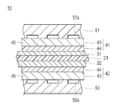
- FIG. 2 is a cross-sectional view showing the main parts of a polymer electrolyte fuel cell.
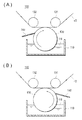
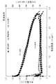
- FIGS. 2A and 2B are schematic configuration diagrams showing a coating apparatus for applying a coating liquid. It is a figure which shows the example of the electric power generation evaluation result in wet condition. It is a figure which shows the example of the electric power generation evaluation result in dry conditions.
- an anode catalyst layer 31 and a cathode catalyst layer 32 are disposed opposite each other on both sides of a solid polymer electrolyte membrane 21,
- An anode gas diffusion layer 41 is disposed between the layer 31 and the anode separator 51, and a cathode gas diffusion layer 42 is disposed between the cathode catalyst layer 32 and the cathode separator 52.
- the fuel gas is supplied through the supply groove 51 a provided in the anode separator 51.
- the oxidant gas is supplied through a supply groove 52 a provided in the cathode separator 52.
- the gas diffusion layers 41 and 42 have a function of supplying the fuel gas and the oxidant gas supplied to the fuel cell 10 to the catalyst layers 31 and 32, and a function of transferring electrons between the catalyst layers 31 and 32 and the separators 51 and 52. And.
- the gas diffusion layers 41 and 42 according to the embodiment include the base material layer 43 and the conductive fine particle layer 44, and can efficiently discharge generated water by having excellent water repellency and the gradient thereof. it can.
- the base layer 43 has a porous structure for sufficiently diffusing the fuel gas or oxidant gas supplied from the outside, and a group having sufficient conductivity for collecting electrons generated by the power generation reaction. Any material may be used.
- the material of the base material 45 which comprises the base material layer 43 is not specifically limited, The conventionally well-known knowledge can be referred suitably. Specifically, a sheet-like material having conductivity and porosity, such as a carbon woven fabric, a paper-like paper body, a felt, and a non-woven fabric, can be mentioned. By using a porous sheet-like material, the gas supplied from the outside can be uniformly diffused in the base material layer 43. More specifically, a base material 45 such as carbon paper, carbon cloth, carbon non-woven fabric, etc. may be preferably mentioned. The excellent electron conductivity of the base layer 43 achieves efficient transport of electrons generated by the power generation reaction, and the performance of the fuel cell 10 is improved.
- the base material layer 43 preferably contains a water repellent.
- the water repellent agent is not particularly limited, but may be a fluorine-based polymer such as polytetrafluoroethylene (PTFE), polyvinylidene fluoride (PVDF), polyhexafluoropropylene or tetrafluoroethylene-hexafluoropropylene copolymer (FEP).
- PTFE polytetrafluoroethylene
- PVDF polyvinylidene fluoride
- FEP tetrafluoroethylene-hexafluoropropylene copolymer
- the thickness of the base layer 43 may be appropriately determined in consideration of the properties of the gas diffusion layers 41 and 42 to be obtained, but may be about 30 to 500 ⁇ m. If the thickness of the substrate 45 is a value within such a range, the balance between mechanical strength and permeability such as gas and water can be appropriately controlled.
- the air permeability (Gurley air permeability) of the base material layer 43 is preferably 0.05 seconds or more, more preferably 0.06 seconds or more, still more preferably 0.07 seconds or more, and still more preferably 0.08 seconds or more.
- 0.1 or more is particularly preferable. 1 or less is preferable, 0.8 second or less is more preferable, 0.7 second or less is further more preferable, 0.6 second or less is still more preferable, and 0.5 second or less is especially preferable.
- the coating liquid of the conductive fine particle layer 44 can ensure excellent gas diffusivity without leaking to the back surface.
- “air permeability (Gurley air permeability)” means a value measured in accordance with JIS P8117: 1998.
- 1 second or more is preferable, 2 seconds or more are more preferable, 5 seconds or more are more preferable, 10 seconds or more are further more preferable, and 20 seconds or more are preferable. It is more preferable, and 30 or more is particularly preferable. 100 seconds or less are preferable, 80 seconds or less are more preferable, 70 seconds or less are more preferable, 60 seconds or less are still more preferable, and 50 seconds or less are especially preferable. Within such a range, a sufficient amount of the conductive fine particle layer 44 can cover the base material layer 43, and excellent gas diffusivity can be ensured.
- the conductive particle layer 44 preferably contains conductive particles and a binder. Since electrons generated by the electrode reaction flow, high conductivity can be imparted to the conductive particle layer 44 by using the conductive particles. Further, by including a binder, a strong pore structure can be produced and maintained.
- the conductive fine particles play a role of transferring electrons generated by the electrode reaction to the base layer 43.
- the conductive fine particles are preferably those that are chemically stable at the positive electrode potential and the negative electrode potential.
- carbon particles, Ag particles, Au particles, Cu particles, Ti particles, or SUS particles are used for the anode gas diffusion layer 41.
- carbon particles, Al metal particles, or SUS particles are used for the cathode gas diffusion layer 42.
- carbon particles are used for the gas diffusion layers 41 and 42 on the anode side and / or the cathode side.
- the carbon particle has a wide potential window, is stable when used for either positive electrode potential or negative electrode potential, and is excellent in conductivity.
- the conductive fine particles may be used alone or in the form of a mixture of two or more.
- the carbon particles may be those having excellent electron conductivity, and examples thereof include carbon black, graphite, expanded graphite and the like. Among them, carbon blacks such as oil furnace black, channel black, lamp black, thermal black and acetylene black are preferable because they are excellent in electron conductivity and large in specific surface area.
- the size of the conductive particles is not particularly limited.
- the conductive fine particles preferably have an average particle size (average primary particle size) of 10 to 100 nm.
- the “average particle diameter (average primary particle diameter)” in the present invention indicates a crystallite diameter determined from the half value width of the diffraction peak of the conductive fine particles in X-ray diffraction.
- the binder plays a role of binding the conductive fine particles.
- fluorine-based polymer materials such as polytetrafluoroethylene (PTFE), polyvinylidene fluoride (PVDF), polyhexafluoropropylene, tetrafluoroethylene-hexafluoropropylene copolymer (FEP), polypropylene, polyethylene, etc.
- PTFE polytetrafluoroethylene
- PVDF polyvinylidene fluoride
- FEP tetrafluoroethylene-hexafluoropropylene copolymer
- a fluorine-based polymer material is preferably used because it is excellent in water repellency and corrosion resistance at the time of electrode reaction, and polytetrafluoroethylene (PTFE) is particularly preferable.
- the shape of the binder may be in the form of particles, fine particles, indeterminate shapes or the like.
- the lower limit of the binder content in the conductive particle layer 44 is preferably 10% by mass or more, more preferably 15% by mass or more, and further preferably 20% by mass or more, based on the total mass of the conductive particle layer 44. % Or more is still more preferable, and 30 mass% or more is especially preferable. If it is less than 10% by mass, the bonding between the conductive fine particles may be weak, which is not preferable. 60 mass% or less is preferable with respect to the total mass of the conductive fine particle layer 44, as for the upper limit of content of the binder in the conductive fine particle layer 44, 55 mass% or less is more preferable, 50 mass% or less is more preferable, 45 mass% % Or less is more preferable, and 40% by mass or less is particularly preferable. If it exceeds 60% by mass, the pores are blocked by the binder, and the gas diffusivity may be reduced, which is not preferable. Moreover, since an electrical resistance may increase by excess binder, it is unpreferable.
- the lower limit of the basis weight by weight of the conductive microparticle layer 44 (weight per 1 m 2 of the gas diffusion layers 41 and 42) is preferably at least 10 g, more preferably at least 15 g, more 20g is further preferred.
- the upper limit of the coating weight of the conductive fine particle layer 44 is preferably 100 g or less, more preferably 75 g or less, still more preferably 50 g or less, and still more preferably 40 g or less.
- Method of manufacturing gas diffusion layers 41 and 42 In the method of manufacturing the gas diffusion layers 41 and 42, the step of preparing a coating liquid for forming the conductive fine particle layer 44 (first step), on the surface of the base material 45 for forming the base material layer 43 A step of applying the coating solution to the transfer section for applying the coating solution to the substrate 45 by using a gravure roll by a kiss method, in particular, a kiss method in which the backup roll is not disposed (second step And the step of heat-treating the substrate 45 coated with the conductive fine particle layer 44 (third step).
- the coating apparatus 100 does not arrange
- the kiss method is used.
- the coating apparatus 100 is disposed on the opposite side of the gravure roll 120 with respect to the tank 110 for storing the coating liquid 111, the gravure roll 120 rotatably disposed on the top of the tank 110, and the base material 45 to be transported.
- a pair of pressing rolls 131 and 132 and a doctor blade 140 in contact with the outer circumferential surface of the gravure roll 120 are provided.
- the pressing rolls 131 and 132 are also referred to as hold down rolls, guide rolls, or stretching rolls.
- the gravure roll 120 rotates in the clockwise direction
- the gravure roll 120 rotates in the counterclockwise direction.
- the base material 45 is conveyed in the left direction in FIG. 2 (A) (B).
- the pair of pressing rolls 131 and 132 are disposed above the gravure roll 120 and on the upstream side and the downstream side of the gravure roll 120 along the transport direction of the substrate 45. It is sufficient that the entire base material 45 is in contact with the gravure roll 120 by the spreading tension.
- the base material 45 is in contact with the gravure roll 120 via the pressure roll 131 and is further conveyed via the pressure roll 132.
- the portion where the substrate 45 contacts the gravure roll 120 is a transfer portion between the substrate 45 and the coating liquid 111.
- the doctor blade 140 is disposed upstream of the transfer unit with respect to the rotational direction of the gravure roll 120. The doctor blade 140 scrapes off the excess coating liquid 111 on the outer circumferential surface of the gravure roll 120.
- the impression roll is disposed in the same manner as the pressing rolls 131 and 132, it can be a kiss system.
- the main components of the coating liquid 111 (slurry) for forming the conductive fine particle layer 44 are conductive fine particles, a binder, and a solvent, but an additive such as a surfactant can be added as needed.
- the coating liquid 111 i.e., the gas diffusion layers 41 and 42
- a catalyst component such as a noble metal, particularly platinum.
- the coating liquid 111 is preferably composed of conductive fine particles (more preferably carbon particles), a binder, a surfactant and a solvent.
- the solvent is not particularly limited, and examples thereof include water, lower alcohols such as methanol, ethanol and isopropanol, acetone, methyl ethyl ketone (MEK) and the like.
- Triisostearin such as polyoxyethylene glyceryl isostearate, PEG-10 glyceryl triisostearate, PEG-20 glyceryl triisostearate, PEG-20 glyceryl triisostearate
- Nonionic surfactants such as polyoxyethylene glyceryl and the like like.
- the dispersing machine used for preparation of the coating liquid 111 can use simple dispersing machines, such as a propeller type
- the rotation speed during stirring in each of the above steps is 1 to 300 rpm, more preferably 80 to 200 rpm in step 1), 80 to 5000 rpm in step 2), more preferably 80 to 200 rpm, 1 in step 3). Conditions such as ⁇ 300 rpm, more preferably 80-200 rpm can be used.
- the number of revolutions of the stirrer may be adjusted between 1 to 5000 rpm, preferably 80 to 5000 rpm, depending on the form of the coating liquid 111 and the dispersion time, or the same number of revolutions may be used in all steps.
- the stirring and dispersion time of each step is preferably 1 minute to 4 hours, more preferably 1 to 2 hours or less.
- steps 1) and 2) can be carried out continuously as the same step.
- the conditions of steps 1) and 2) are not particularly limited, but it is preferable that dispersion is carried out by stirring at a low rotational speed (under low shear conditions). That is, the coating liquid is preferably prepared by adding a binder after stirring carbon particles as a conductive fine particle material, a surfactant and a solvent at a low rotational speed. More preferably, the carbon particles, the surfactant and the solvent are mixed by stirring with a propeller stirrer at a low rotational speed (under low shear conditions) of 80 to 200 rpm for 1 minute to 4 hours, and then adding a binder. Prepare a coating solution.
- a solvent may be further added.
- the apparent viscosity ⁇ [Pa ⁇ s] of the coating liquid and the solid content (concentration) ⁇ [wt%] of the conductive fine particles can be easily adjusted to an appropriate range.
- the solvent is not particularly limited, and the same solvents as described above can be used.
- the solvent used in step 1) and the solvent used in step 3) may be the same or different, but it is preferable in consideration of the operation in the production process, etc. Is the same.
- the coating liquid 111 It is preferable to stir the coating liquid 111 at the time of dispersion
- concentration high electroconductive fine particle density
- concentration high electroconductive fine particle density
- ink low concentration or low viscosity ink
- the coating liquid 111 which has been prepared and becomes paste-like is in a state of high viscosity, many air bubbles, and no fluidity, but it also has features of the coating apparatus 100 described later. For this reason, although degassing processing etc. may be performed, it is not necessary to necessarily perform degassing processing etc.
- the coating liquid 111 used for the coating apparatus 100 is a liquid having thixotropy, and the apparent viscosity ⁇ [Pa ⁇ s] at 25 ° C. with a B-type viscometer is 1.0 ⁇ ⁇ 200.0 (3 rpm) 0.2 ⁇ ⁇ 10.0 (30 rpm) And preferably 2.0 ⁇ 100.0 (3 rpm) 0.3 ⁇ ⁇ ⁇ 9.0 (30 rpm) And more preferably 3.0 ⁇ ⁇ 40.0 (3 rpm) 0.5 ⁇ ⁇ 8.0 (30 rpm) And particularly preferably 6.0 ⁇ 25.0 (3 rpm) 1.4 ⁇ 6.0 6.0 (30 rpm) It is.
- the concentration of the coating liquid 111 in which the conductive fine particle material is dispersed that is, the solid content (concentration) ⁇ [wt%] of the conductive fine particles with respect to the coating liquid 111 is 10 ⁇ ⁇ ⁇ 90 Is preferred, more preferably 12 ⁇ ⁇ ⁇ 60 And particularly preferably 13 ⁇ ⁇ 40 It is.
- the viscosity and solid content are not smaller than the above ranges, the phenomenon that the coating liquid 111 exudes, the coating formation of the fine conductive fine particle layer 44 does not become difficult, and the water repellent effect does not decrease either. It is preferable because the conductive fine particle layer 44 excellent in the flooding resistance can be produced.
- the gravure roll 120 can pick up the coating liquid 111 in the coating step, which is more preferable.
- the coating amount (coating amount of the conductive fine particles) ⁇ [g / m 2 ] of the coating liquid 111 necessary to produce the gas diffusion layers 41 and 42 can be adjusted according to the properties of the substrate 45 But 5 ⁇ ⁇ ⁇ 100 Is preferred, 10 ⁇ ⁇ ⁇ 50 Is more preferable, 18 ⁇ ⁇ ⁇ 30 Is more preferred.
- the coating amount of the coating liquid 111 does not become smaller than the above range ( ⁇ does not become less than 5 g / m 2 ), the base layer 43 is exposed on the surface without a shortage of the coating amount on the base layer 43 It is preferable.
- the coating amount of the coating liquid 111 does not exceed the above range ( ⁇ does not exceed 100 g / m 2 ), the cost for the conductive fine particle material does not increase, and an excessive layer of conductive fine particles is obtained. It is preferable because the performance of the gas diffusion layers 41 and 42 is unlikely to deteriorate depending on the thickness.
- the coating solution prepared in the above first step is applied to at least one surface of the substrate by using a gravure roll and a transfer unit for applying the coating solution to the substrate. It is a process of coating by a method.
- the coating liquid may be applied to the surface of at least one of the catalyst layers 31 and 32 and the separators 51 and 52 of the substrate.
- the coating liquid is applied to the surface of the base on the catalyst layer 31, 32 side.
- the coating apparatus 100 shown to FIG. 2 (A) (B) is called a kiss gravure coater, and is 1 type of a coating means of a pre-mass type system (regulation application type
- This type of coating means is of a type in which a predetermined coating amount is measured before transferring the coating liquid 111 to the substrate 45, so that the coating film thickness becomes uniform, and at the same time, the speed of the roll and the line is increased. A difference can be generated to add surface smoothness to the coated surface.
- the pressure acting on the contact surface for transferring the coating liquid 111 to the base material 45 is only the spreading tension from the pressing rolls 131 and 132. For this reason, when using a backup roll, it is possible to reduce the load on the substrate 45 due to shear, friction and the like generated with the gravure roll 120. By this, it is possible to reduce or prevent scratching of the coated surface, which is likely to occur, breakage of the base material 45 and the like. As a result, the productivity of the smooth conductive fine particle layer 44 can be enhanced, and the quality of the gas diffusion layers 41 and 42 can be improved. Since the surface of the conductive fine particle layer 44 immediately after transfer is excellent in smoothness, the contact resistance of the gas diffusion layers 41 and 42 in the cell performance can be reduced. Furthermore, it becomes easy to manipulate the pore structure and pore size distribution in the conductive particle layer 44, and the flooding phenomenon can be suitably suppressed.
- the absolute value of the peripheral velocity GR [m / min] of the gravure roll 120 has the substrate 45 in order to coat the conductive fine particle layer 44 smoothly.
- the absolute value of the line speed LS [m / min] to be transported is preferably larger.
- the ratio between the circumferential speed GR [m / min] of the gravure roll 120 and the line speed LS [m / min] is preferably -1 ⁇ LS / GR ⁇ 1 (however, LS / GR ⁇ 0) And more preferably -0.8 ⁇ LS / GR ⁇ 0.8 (however, LS / GR ⁇ 0) And even more preferably, -0.5 ⁇ LS / GR ⁇ 0.5 (however, LS / GR ⁇ 0) And more preferably -0.3 ⁇ LS / GR ⁇ 0.3 (however, LS / GR ⁇ 0) And particularly preferably ⁇ 0.2 ⁇ LS / GR ⁇ 0.2 (however, LS / GR ⁇ 0) Is the range that satisfies
- the negative numerical value of LS / GR indicates that the gravure roll 120 is reversely rotated in the reverse direction with respect to the transport direction of the substrate 45
- the positive numerical value of LS / GR indicates that the gravure roll 120 is the substrate. It represents that it is positively rotated along the 45 conveyance directions.
- a coating method in which the reverse rotation is performed is called a kiss reverse gravure (or reverse kiss gravure) coater (FIG. 2A), and a positive rotation is called a kiss gravure coater (FIG. 2B).
- the kiss reverse gravure (or reverse kiss gravure) method is a coating method in which the gravure roll is reversely rotated in the reverse direction with respect to the conveyance direction of the substrate, considering the easiness of the manufacturing process, etc. preferable.
- the coating amount of the coating liquid particularly, conductive fine particles
- the kiss gravure (or reverse kiss gravure) method can be easily secured even with the same LS / GR value, compared to the kiss gravure. .
- the coating liquid 111 is prepared with a high viscosity (concentration) to suppress the exudation of the coating liquid 111, that is, the coating liquid 111 having poor leveling property and the base material 43 having porosity and poor smoothness.
- the amount of coating required for coating will necessarily be large compared to the case where it is not used. Therefore, it can pick up the coating liquid 111 required in order to laminate the conductive fine particle layer 44 on the surface of such a substrate 43 as it is in the above-mentioned range, and a sufficient amount of application can be secured.
- Another effect is that it is possible to level or smooth only the surface layer of the conductive fine particle layer 44 in which the shear force by the velocity ratio LS / GR is formed. Even if the coating liquid 111 has many bubbles and high viscosity and is poor in leveling property, bubbles on the surface of the coating liquid 111 are simultaneously transferred using the irregularities of the gravure roll 120 and the roll rotation at the same time as the coating liquid 111 is transferred. As well as squeezing the rough plate of the gravure (leveling effect and smoothing effect). This makes it possible to obtain the conductive fine particle layer 44 having a smooth coated surface and a uniform thickness.
- the coating amount of the coating liquid 111 tends to increase and the smoothness of the surface of the conductive fine particle layer 44 tends to improve, and the pore structure and pores
- the optimum velocity ratio LS / GR is set in accordance with the gas diffusion layers 41 and 42 which are considered to have desirable performance such as distribution.
- the preferable range of the line speed LS varies depending on the coating apparatus 100, but is typically 0.5 to 200 m / min.
- the circumferential speed GR of the gravure roll 120 is larger than 0.5 m / min, and more preferably larger than 1.0 m / min.
- the circumferential speed GR of the gravure roll 120 is larger than 200 m / min, more preferably larger than 400 m / min. If the line speed LS is out of the range of 0.5 to 200 m / min, the productivity of the product may be impaired, the design of the coating apparatus 100 may become difficult, or the conductive particle layer 44 having stable performance and quality. Supply may be difficult.
- the cup shape of the gravure cell includes a lattice (trapezoidal) cup, a pyramid cup, a tortoise cup, a triangular diagonal cup, a trapezoidal diagonal cup, and the like.
- the application amount can be adjusted by the mesh number and depth ( ⁇ m) of the cup.
- the mesh number represents the number of divisions per arbitrary unit area (square inch) on the roll surface or per unit length (inch) in any direction, and the mesh number is 10 to 400 and the depth is 400 to 5 ⁇ m. Is preferably used. Generally, as the number of meshes decreases, the depth tends to increase and the amount of application increases.
- the engraving pattern of the gravure roll 120 is not limited. Gravure processing is originally derived from printing technology, but if the surface of the conductive fine particle layer 44 has smoothness and the layer thickness can be coated uniformly, the engraving pattern is not limited. For example, complicated engraving patterns such as Euclidean geometry and fractal geometry may be used. It is preferable to select the type of roll suitable for the coating liquid 111 and the type of roll suitable for the design of the gas diffusion layers 41 and 42 to be produced.
- the outer diameter of the gravure roll 120 is 20 mm or more, preferably 50 mm or more, more preferably 60 mm or more, and still more preferably 120 mm or more.
- the upper limit of the outer diameter of the gravure roll 120 is not particularly limited, but is preferably 500 mm or less, more preferably 250 mm or less, and even more preferably 200 mm or less.
- the outer diameter of the gravure roll 120 is less than 20 mm, the number of rotations necessary to achieve the necessary circumferential speed GR becomes excessive, and the conductive fine particle layer 44 having the scattering of the coating liquid 111 and a smooth surface can not be produced.
- the gravure roll 120 having a roll diameter of 20 to 50 mm may be called microgravure (registered trademark).
- Microgravure registered trademark
- Microgravure is a 10 ⁇ m thick or less (applying amount of about 10 g / m 2 or less), preferably 2 to 3 ⁇ m (coating amount), using a low viscosity coating liquid 111 of 1.0 Pa ⁇ s or less. In some cases, this method is not preferable because it is mainly used for coating a thin film of about 2 to 3 g / m 2 ).
- the width of the gravure roll 120 is preferably 200 to 2000 mm.
- the gravure roll 120 may be provided with a doctor blade 140 for scraping off the coating liquid 111 adhering to the surface before coating on the substrate 45. It is possible. There are no particular restrictions on the installation conditions or the location as long as the object of the present invention is not impaired.
- the material of the doctor blade is Swedish steel or ceramic, and examples of the thickness thereof include 100 ⁇ m, 150 ⁇ m, 200 ⁇ m and the like, but there is no particular limitation.
- there are no particular restrictions on the setting conditions of the doctor blade 140 such as the contact angle of the cutting edge.
- a metalling roll or the like may be used instead of the doctor blade 140.
- the supply system of the coating liquid 111 may be, for example, an open or closed paint pan, but is not particularly limited. However, since it is desirable that the coating liquid 111 be constantly stirred or circulated, it is better to be able to continuously supply the coating liquid 111 as compared to the batch type or semi-batch type.
- the gravure roll 120 may be provided with a supply system provided with an extrusion (die) method, a lip method, a fountain method, or the like.
- the base material 45 coated with the conductive fine particle layer 44 is subjected to heat treatment to be sintered, and the water repellent (binder) particles and the carbon black particles are thermally fused to obtain conductive fine particles. Make layer 44 stable.
- the substrate 45 coated with the conductive fine particle layer 44 is introduced into a drying oven at room temperature or more, preferably 60 ° C. or more, more preferably 100 ° C. or more, and dried.
- the upper limit of the temperature of the drying furnace is not particularly limited, it is preferably 350 ° C. or less and 200 ° C. or less in consideration of the stability of the structure and performance of the base material layer and the conductive fine particle layer. Is preferred.
- the drying time in the drying furnace of the substrate 45 coated with the conductive fine particle layer 44 is also not particularly limited, and may be appropriately selected depending on the application amount of the coating liquid and the like. The drying time is preferably 1 second to 20 minutes. There is no restriction
- the dried gas diffusion layers 41 and 42 are sintered to thermally fuse the conductive fine particles and the binder.
- the sintering temperature can be suitably selected by those skilled in the art according to the binder, but in the case of using PTFE, 330 ° C. or more is preferable, 340 ° C. or more is more preferable, and 350 ° C. or more is more preferable.
- the upper limit of the sintering temperature is not particularly limited, but is preferably 400 ° C. in consideration of the stability of the structure and performance of the base material layer and the conductive fine particle layer. 1 minute or more is preferable and, as for sintering time, 10 minutes or more are more preferable.
- the upper limit of the sintering time is also not particularly limited, but is preferably 2 hours in consideration of the stability of the structure and performance of the base material layer and the conductive fine particle layer.
- the membrane electrode assembly is a five-layered assembly of gas diffusion layer 41-catalyst layer 31-electrolyte membrane 21-catalyst layer 32-gas diffusion layer 42, and is combined with separators 51 and 52 to supply oxygen and hydrogen.
- the fuel cell 10 has a function of configuring the fuel cell 10.
- the surface provided with the catalyst layer on the hydrogen side is called an anode
- the surface provided with the catalyst layer on the oxygen side is called a cathode.
- a fuel cell composed of a pair of membrane electrode assemblies and separators 51 and 52 may be referred to as a single cell.
- the membrane electrode assembly may be called MEA (membrane electrode assembly), and the gas diffusion layers 41, 42 may be called GDL (gas diffusion lyaer).
- catalyst layer 31-electrolyte membrane 21-catalyst layer 32 are CCM (catalyst coated membrane), two layers of catalyst layer 31 (32)-gas diffusion layer 41 (42) are a gas diffusion electrode or GDE ( It may be called gas diffusion electrode).
- GDE gas diffusion electrode
- the gas diffusion electrode may be simply referred to as the electrode.
- the electrolyte membrane 21 is a kind of selectively permeable membrane having a function of transporting protons and insulating electrons.
- the electrolyte membrane 21 is roughly classified into a fluorine-based electrolyte membrane and a hydrocarbon-based electrolyte membrane according to the type of ion exchange resin which is a constituent material.
- the fluorine-based electrolyte membrane is excellent in heat resistance and chemical stability because it has a C—F bond.
- perfluorosulfonic acid membranes known under the trade name Nafion (registered trademark, manufactured by DuPont) are widely used.
- the cathode catalyst layer 32 is a layer containing an electrocatalyst on which a catalyst component is supported, and an ionomer.
- the electrode catalyst has a function of promoting a reaction (oxygen reduction reaction) in which water is generated from protons, electrons and oxygen.
- the electrode catalyst has, for example, a structure in which a catalyst component such as platinum is supported on the surface of a conductive support made of carbon or the like.
- the anode catalyst layer 31 is a layer containing an electrocatalyst on which a catalyst component is supported, and an ionomer.
- the electrode catalyst has a function of promoting a reaction of dissociating hydrogen into protons and electrons (hydrogen oxidation reaction).
- the electrode catalyst has, for example, a structure in which a catalyst component such as platinum is supported on the surface of a conductive support made of carbon or the like.
- catalyst layers 31 and 32 on the anode side and the cathode side are formed on both sides of the solid polymer electrolyte membrane by using a conventionally known method, and the gas obtained by applying the above method It can be manufactured by sandwiching the diffusion layers 41 and 42.
- the membrane electrode assembly can be manufactured by sandwiching the catalyst layers 31 and 32 formed on the solid polymer electrolyte membrane by the pair of gas diffusion layers 41 and 42 and bonding them.
- the catalyst layers 31 and 32 are formed on one side of the gas diffusion layers 41 and 42, and the solid polymer electrolyte membrane 21 is sandwiched by the pair of gas diffusion layers 41 and 42 such that the catalyst layers 31 and 32 face each other.
- the membrane electrode assembly may be manufactured by joining together.
- the catalyst layers 31 and 32 are formed of a catalyst ink comprising the above electrode catalyst, polymer electrolyte, solvent and the like on a solid polymer electrolyte membrane by a spray method, a transfer method, a doctor blade method, a die coater method, etc. It can be manufactured by coating using a method.
- the coating amount of the solid polymer electrolyte membrane 21 and the catalyst ink is not particularly limited as long as the electrode catalyst can sufficiently exhibit the function of catalyzing the electrochemical reaction, but the mass of the catalyst component per unit area is 0.05 to It is preferable to apply
- the thickness of the catalyst ink to be applied is preferably 5 to 30 ⁇ m after drying. The application amount and thickness of the above-mentioned catalyst ink do not have to be the same on the anode side and the cathode side, and can be appropriately adjusted.
- the thicknesses of the catalyst layers 31 and 32, the gas diffusion layers 41 and 42, and the polymer electrolyte membrane 21 are desirably thin in order to improve the diffusivity of the fuel gas, etc. Sufficient electrode output can not be obtained. Therefore, it may be appropriately determined so as to obtain a membrane electrode assembly having desired properties.
- the fuel cell 10 according to the present embodiment is useful as a stationary power source as well as a mobile power source such as a vehicle having a limited installation space, but in particular, an automobile in which system start / stop and output fluctuation frequently occur. It can be particularly suitably used in applications.
- Example 1 Carbon black as a conductive fine particle, PTFE as a water repellent and a binder of carbon black, and carbon paper as a base of a gas diffusion layer were used.
- a test coater (M-200, manufactured by Hirano Tech Seed Co., Ltd.) was used as a coating apparatus used to apply the coating solution.
- a coating roll a kiss type gravure method equipped with a gravure roll and a pressing roll was used.
- the outline of the coating apparatus is as shown in FIG.
- the gravure roll had a diameter of 150 mm and a width of 280 mm, and a grid type 60 (mesh)-150 ⁇ m (depth) was used.
- the line speed LS of the substrate is 0.7 m / min
- the gravure roll circumferential speed GR is 4.1 m / min
- the line speed LS is rotated in reverse so that the speed ratio LS / GR is- It was set to be 0.17.
- the gas diffusion layer coated with the coating liquid is dried for 3 minutes in a drying furnace set at 100 ° C. of a coating machine to dry the solvent and then sintered for 1 hour in a muffle electric furnace set at 350 ° C.
- the gas diffusion layer 1 coated with the conductive fine particle layer was obtained.
- the coating amount of the conductive fine particles (acetylene black) was about 22 g / m 2 .
- the Gurley air permeability of the gas diffusion layer 1 thus obtained was 26 seconds.
- Example 2 (1) Preparation of Coating Liquid (Carbon Black PTFE Dispersion) The same coating liquid as Example 1 was used except that the pure water to be added after the addition of the PTFE dispersion was changed to 99 g. The viscosity (25 ° C.) was 3.0 Pa ⁇ s (3 rpm) and 0.5 Pa ⁇ s (30 rpm).
- the coating conditions and conditions were the same as in Example 1 except that a 150 mm diameter, 280 mm wide grid type 30 (mesh)-260 ⁇ m (depth) was used for the gravure roll, and the gas diffusion layer was used. I got two. At the time of coating, since a coating liquid having a relatively low concentration (viscosity) was used, some of the coating liquid was exuded to a surface different from the coated surface of the substrate. The coating amount of the conductive fine particles was about 22 g / m 2 . Further, the Gurley air permeability of the gas diffusion layer 2 thus obtained was 4 seconds.
- Example 3 (1) Preparation of Coating Liquid (Carbon Black PTFE Dispersion) The same coating liquid as in Example 1 was used.
- the coating apparatus and the coating conditions are the same as in Example 1, but the doctor blade pressure is manually increased to apply the conductive fine particles in an amount of about 19 g / m 2 for gas diffusion. I got layer 3.
- Example 4 (1) Preparation of Coating Liquid (Carbon Black PTFE Dispersion) The same coating liquid as in Example 1 was used.
- the line speed LS of the substrate is 0.7 m / min, and the gravure roll circumferential speed GR is rotated at 3.5 m / min so as to be reverse rotation with the line speed LS direction, and the speed ratio LS / GR is-
- the gas diffusion layer 4 was obtained under the same conditions as in Example 2 except that it was set to 0.2.
- the coating amount of the conductive fine particles was about 29 g / m 2 .
- Example 5 (1) Preparation of Coating Liquid (Carbon Black PTFE Dispersion) The same coating liquid as in Example 1 was used.
- the line speed LS of the substrate is 0.7 m / min, and the gravure roll circumferential speed GR is rotated at 3.2 m / min so as to be reverse rotation with the line speed LS direction, and the speed ratio LS / GR is-
- the gas diffusion layer 5 was obtained under the same conditions as in Example 2 except that it was set to 0.22.
- the coating amount of the conductive fine particles was about 27 g / m 2 .
- Comparative Example 1 (1) Preparation of Coating Liquid (Carbon Black PTFE Dispersion)
- the material of the coating liquid was the same as in Example 1.
- 45 g of acetylene black, 3 g of surfactant, and 232 g of pure water are put into a 500 mL beaker, and two stirring blades (soft cross) are installed on a propeller type stirrer (made by HEIDON, three one motor BL300), and the rotation speed is 80 to 100 rpm
- the mixture was stirred for 30 minutes and premixed.
- the mixture was stirred for 2 hours at a rotational speed of 2000 to 3000 rpm using a homogenizer (TK Robot Mix type F Model, manufactured by Tokushu Kika Kogyo Co., Ltd.).
- TK Robot Mix type F Model manufactured by Tokushu Kika Kogyo Co., Ltd.
- 20 g of a PTFE dispersion was added and stirred with a propeller stirrer for 1 hour at a rotational speed of 100 rpm to obtain a coating liquid .
- the coating solution was degassed under reduced pressure before coating.
- the viscosity (25 ° C.) was 10.7 Pa ⁇ s (3 rpm) and 1.2 Pa ⁇ s (30 rpm).
- the coating method of the conductive fine particle layer was hand-painted using a baker type applicator. At the time of coating, a large amount of the coating liquid was exuded to the surface different from the coated surface of the substrate. After coating, it was sintered in a muffle electric furnace set at 350 ° C. for 1 hour to obtain a comparative gas diffusion layer 1 coated with a conductive fine particle layer.
- the coating amount of the conductive fine particles was about 22 g / m 2 .
- Comparative Example 2 (1) Preparation of Coating Liquid (Carbon Black PTFE Dispersion) The same coating liquid as in Example 1 was used.
- the line speed LS of the substrate is 0.7 m / min
- the gravure roll circumferential speed GR is 0.7 m / min
- the line speed LS direction is positive rotation so that the speed ratio LS / GR is 1.0
- the comparative gas diffusion layer 2 was obtained under the same conditions as in Example 1 except that it was set as follows. The coating test was conducted, but under these conditions, the gravure roll can not sufficiently pick up and apply the coating liquid having high viscosity, so that paint spots and scums are generated to expose the substrate surface and conductive fine particles. Coating of the layer was not possible.
- the coating amount of the conductive fine particles was about 4 g / m 2 .
- Comparative Example 3 (1) Preparation of Coating Liquid (Carbon Black PTFE Dispersion) The same coating liquid as in Example 1 was used.
- the line speed LS of the substrate is 0.7 m / min, and the gravure roll peripheral speed GR is rotated at 0.7 m / min so as to be reverse rotation with the line speed LS direction, and the speed ratio LS / GR is-
- the comparative gas diffusion layer 3 was obtained under the same conditions as in Example 1 except that it was set to 1.0. Although the coating test was implemented, it became a result substantially the same as the comparative example 2, and coating formation of the electroconductive fine particle layer was impossible.
- the coating amount of the conductive fine particles was about 6 g / m 2 .
- Comparative Example 4 (1) Preparation of Coating Liquid (Carbon Black PTFE Dispersion) The same coating liquid as in Example 1 was used except that the amount of pure water to be added after the addition of the PTFE dispersion was 219 g. The viscosity (25 ° C.) was 1.0 Pa ⁇ s (3 rpm) and 0.2 Pa ⁇ s (30 rpm).
- the coating apparatus and the coating conditions were set to the same conditions as in Example 1 except that a 150 mm diameter, 280 mm wide grid type 17 (mesh)-430 (depth) was used for the gravure roll, and the comparison gas diffusion was made. I got layer 4.
- the coating test was carried out, but a large amount of the coating liquid was exuded on a surface different from the coated surface of the substrate, and a ridge-like streak was generated, and the concave portion had the substrate surface exposed and the conductive fine particles Coating of the layer was not possible.
- the coating amount of the conductive fine particles was about 17 g / m 2 .
- Comparative Example 5 (1) Preparation of Coating Liquid (Carbon Black PTFE Dispersion) The same coating liquid as in Example 1 was used except that 39 g of pure water to be added after the addition of the PTFE dispersion was used. The viscosity (25 ° C.) was 6.7 Pa ⁇ s (3 rpm) and 1.4 Pa ⁇ s (30 rpm).
- Example 2 The same coating apparatus as in Example 1 was used.
- a coating roll a direct type gravure method in which a pressure roll was installed at a gravure roll and a transfer portion of a coating liquid was used.
- the gravure roll had a diameter of 150 mm and a width of 280 mm, and a lattice type 17 (mesh) -430 (depth) was used.
- the line speed LS of the substrate is 0.7 m / min
- the gravure roll speed GR is 0.7 m / min and it rotates so as to be the same positive rotation as the line speed LS direction, and the speed ratio LS / GR becomes 1.0. It was set up.
- the other conditions were the same as in Example 1 to obtain a comparative gas diffusion layer 5.
- the surface of the coating is not smooth due to the transfer of the concavo-convex pattern of the gravure plate, and the surface of the substrate is exposed due to the occurrence of paint spots on the surface of the coating corresponding to the convex portions of the gravure. Coating formation was impossible.
- the coating amount of the conductive fine particles was about 16 g / m 2 .
- a membrane electrode assembly is produced according to the following procedure using each gas diffusion layer produced in Examples 1 to 5 and Comparative Example 1, and the power generation performance of the membrane electrode assembly is measured to evaluate each gas diffusion layer. Did.
- the catalyst ink is applied on one side of a Teflon sheet using a screen printer, and dried at 25 ° C. in the atmosphere for 6 hours to form a catalyst layer (a platinum weight of 0 per 1 cm 2 area) on the Teflon sheet. .4 mg) was prepared.
- the resulting bonded body was sandwiched between two of the gas diffusion layers prepared earlier, with the base layer facing the outside, and this was sandwiched with a graphite separator, and then gold-plated stainless steel It was held by a current collector to make a single cell for evaluation.
- FIG. 3 An example of the power generation evaluation result under wet conditions is shown in FIG. As shown in FIG. 3, the cells using the gas diffusion layers of Examples 1 and 2 exhibited high voltage even at high current densities and exhibited good performance.
- the voltage tended to decrease slightly at high current density.
- the cell using the gas diffusion layer of Comparative Example 1 has a relatively low concentration (viscosity) of the coating solution, and the conductive fine particle layer is further coated for manual application (that is, after-weighing system) application using a baker type applicator. It penetrated into the base material layer too much to make large pores in the conductive fine particle layer, resulting in the loss of the efficiency of liquid water discharge.
- FIG. 4 An example of the power generation evaluation result under dry conditions is shown in FIG. As shown in FIG. 4, the cells using the gas diffusion layers of Examples 1 and 2 and Comparative Example 1 exhibited substantially the same performance.
- the cells using the gas diffusion layers of Examples 1 and 2 can improve the flood resistance without impairing the dry out resistance. From these results, it is considered that the cell using the gas diffusion layer of the present invention is excellent in both the dryout resistance and the flooding resistance, and can achieve both of them, so that it can be suitably adapted to the load fluctuation.
- a fuel cell in which the coating surface of the conductive fine particle layer is smooth and the base material surface is not exposed and the penetration of the conductive fine particle layer into the base material layer is controlled
- a gas diffusion layer can be produced, and a fuel cell using the gas diffusion layer has both flood resistance and dryout resistance even at high current density compared to a cell using a conventional gas diffusion layer
- high voltage can be maintained under wet conditions, and good performance is exhibited.
- the load fluctuation adaptability is excellent, which is higher in flood resistance than the prior art even if the dry out resistance is the same. It is possible to produce a gas diffusion layer.
Abstract
Description
ガス拡散層41、42は、燃料電池10に供給された燃料ガスおよび酸化剤ガスを触媒層31、32へ供給する機能と、触媒層31、32およびセパレータ51、52間で電子を授受する機能と、を有している。実施形態のガス拡散層41、42は、基材層43と導電性微粒子層44とを含んでおり、優れた撥水性とその勾配を有することによって、生成した水を効率的に排出することができる。 (
The
基材層43は、外部から供給された燃料ガスまたは酸化剤ガスを十分に拡散させるための多孔質構造を有し、発電反応によって生成した電子を集電するための十分な導電性を有する基材からなるものであればよい。 (Base material layer 43)
The
導電性微粒子層44は、好ましくは導電性微粒子およびバインダーを含む。電極反応によって生じた電子が流れるため、導電性微粒子を用いることによって、導電性微粒子層44に高い導電性を付与することができる。また、バインダーを含むことによって、強固な空孔構造を作製、維持することができる。 (Conductive particle layer 44)
The
ガス拡散層41、42の製造方法は、導電性微粒子層44を形成するための塗工液を調製する工程(第一の工程)、基材層43を形成するための基材45の表面に、塗工液を、グラビアロールを用いて、かつ、塗工液を基材45に塗工する転写部に、キス方式、特にバックアップロールを配置しないキス方式によって塗工する工程(第二の工程)、そして、導電性微粒子層44を塗工した基材45を加熱処理する工程(第三の工程)、を有する。 (Method of manufacturing gas diffusion layers 41 and 42)
In the method of manufacturing the gas diffusion layers 41 and 42, the step of preparing a coating liquid for forming the conductive fine particle layer 44 (first step), on the surface of the
導電性微粒子層44を形成するための塗工液111(スラリー)の主成分は導電性微粒子とバインダーおよび溶剤であるが、必要に応じて界面活性剤等の添加剤を加えることができる。塗工液111(すなわち、ガス拡散層41、42)は、貴金属などの触媒成分、特に白金を含まないことが好ましい。このため、塗工液111は、導電性微粒子(より好ましくはカーボン粒子)、バインダー、界面活性剤および溶剤から構成されることが好ましい。この際、溶剤は、特に制限されないが、例えば、水、メタノール、エタノール、イソプロパノール等の低級アルコール、アセトン、メチルエチルケトン(MEK)などが挙げられる。また、界面活性剤もまた、特に制限されないが、例えば、ポリオキシエチレン-p-t-オクチルフェノール(オキシエチレン数=9,10)[(polyoxyethylene-p-t-octylphenol;TritonX-100)]、ポリオキシエチレンラウリルエーテル、ポリオキシエチレンセチルエーテル、ポリオキシエチレンオレイルエーテル、ポリオキシエチレンステアリルエーテル、イソステアリン酸PEG-5グリセリル、イソステアリン酸PEG-15グリセリル、イソステアリン酸PEG-20グリセリル、イソステアリン酸PEG-30グリセリル等のイソステアリン酸ポリオキシエチレングリセリル、トリイソステアリン酸PEG-10グリセリル、トリイソステアリン酸PEG-20グリセリル、トリイソステアリン酸PEG-20グリセリル等のトリイソステアリン酸ポリオキシエチレングリセリル等の非イオン系界面活性剤がなど挙げられる。 (First step: preparation of coating liquid 111)
The main components of the coating liquid 111 (slurry) for forming the conductive
1.0<η<200.0 (3rpm)
0.2<η<10.0 (30rpm)
であり、好ましくは、
2.0≦η≦100.0 (3rpm)
0.3≦η≦9.0 (30rpm)
であり、より好ましくは、
3.0<η<40.0 (3rpm)
0.5<η<8.0 (30rpm)
であり、特に好ましくは、
6.0≦η≦25.0 (3rpm)
1.4≦η≦6.0 (30rpm)
である。 The
1.0 <η <200.0 (3 rpm)
0.2 <η <10.0 (30 rpm)
And preferably
2.0 ≦≦≦ 100.0 (3 rpm)
0.3 ≦ η ≦ 9.0 (30 rpm)
And more preferably
3.0 <η <40.0 (3 rpm)
0.5 <η <8.0 (30 rpm)
And particularly preferably
6.0 ≦≦≦ 25.0 (3 rpm)
1.4 η 6.0 6.0 (30 rpm)
It is.
10≦α≦90
が好ましく、より好ましくは、
12≦α≦60
であり、特に好ましくは、
13<α<40
である。 Further, the concentration of the
10 ≦ α ≦ 90
Is preferred, more preferably
12 ≦ α ≦ 60
And particularly preferably
13 <α <40
It is.
5≦γ≦100
が好ましく、
10≦γ≦50
がより好ましく、
18≦γ≦30
がさらに好ましい。 The coating amount (coating amount of the conductive fine particles) γ [g / m 2 ] of the
5 ≦ γ ≦ 100
Is preferred,
10 ≦ γ ≦ 50
Is more preferable,
18 ≦ γ ≦ 30
Is more preferred.
本工程は、基材の少なくとも一方の表面に、上記第一の工程で調製された塗工液を、グラビアロールを用いて、かつ、この塗工液を基材に塗工する転写部にキス方式によって塗工する工程である。ここで、塗工液は、基材の、触媒層31、32側およびセパレータ51、52側の、少なくとも一方の表面に塗工されればよい。好ましくは、図1に示されるように、塗工液は、基材の、触媒層31、32側の表面に塗工される。 (Second step: coating with gravure roll 120)
In this step, the coating solution prepared in the above first step is applied to at least one surface of the substrate by using a gravure roll and a transfer unit for applying the coating solution to the substrate. It is a process of coating by a method. Here, the coating liquid may be applied to the surface of at least one of the catalyst layers 31 and 32 and the
-1<LS/GR<1 (但し、LS/GR≠0)
であり、より好ましくは、
-0.8<LS/GR<0.8 (但し、LS/GR≠0)
であり、さらにより好ましくは、
-0.5<LS/GR<0.5 (但し、LS/GR≠0)
であり、一層好ましくは、
-0.3<LS/GR<0.3 (但し、LS/GR≠0)
であり、特に好ましくは、
-0.2≦LS/GR≦0.2 (但し、LS/GR≠0)
を満たす範囲である。 The ratio between the circumferential speed GR [m / min] of the
-1 <LS / GR <1 (however, LS / GR ≠ 0)
And more preferably
-0.8 <LS / GR <0.8 (however, LS / GR ≠ 0)
And even more preferably,
-0.5 <LS / GR <0.5 (however, LS / GR ≠ 0)
And more preferably
-0.3 <LS / GR <0.3 (however, LS / GR ≠ 0)
And particularly preferably
−0.2 ≦ LS / GR ≦ 0.2 (however, LS / GR ≠ 0)
Is the range that satisfies
第三の工程においては、導電性微粒子層44を塗工した基材45に加熱処理を施して焼結し、撥水剤(バインダー)粒子とカーボンブラック粒子を熱融着させて、導電性微粒子層44を安定にする。 (Third step: heat treatment)
In the third step, the
膜電極接合体は、ガス拡散層41-触媒層31-電解質膜21-触媒層32-ガス拡散層42の5層からなる接合体であり、セパレータ51、52と組み合わせ、酸素および水素を供給することによって、燃料電池10を構成する機能を有する。 (Membrane electrode assembly)
The membrane electrode assembly is a five-layered assembly of gas diffusion layer 41-catalyst layer 31-electrolyte membrane 21-catalyst layer 32-
電解質膜21は、プロトンを輸送し、電子を絶縁する機能を有する一種の選択透過膜である。電解質膜21は、構成材料であるイオン交換樹脂の種類によって、フッ素系電解質膜と炭化水素系電解質膜とに大別される。これらのうち、フッ素系電解質膜は、C-F結合を有しているために耐熱性や化学的安定性に優れる。例えば、Nafion(登録商標、デュポン社製)の商品名で知られるパーフルオロスルホン酸膜が広く使用されている。 (Electrolyte membrane 21)
The
カソード触媒層32は、触媒成分が担持されてなる電極触媒、およびアイオノマを含む層である。電極触媒は、プロトンと電子と酸素とから水を生成する反応(酸素還元反応)を促進する機能を有する。電極触媒は、例えば、カーボンなどからなる導電性担体の表面に、白金などの触媒成分が担持されてなる構造を有する。 (Catalyst layers 31, 32)
The
膜電極接合体は、従来公知の方法を用いて、固体高分子電解質膜の両面にアノード側およびカソード側の触媒層31、32を形成し、これを上記の方法を適用して得られたガス拡散層41、42を用いて挟持することによって製造できる。例えば、固体高分子電解質膜上に形成された触媒層31、32を一対のガス拡散層41、42によって挟持し、これを接合することによって膜電極接合体を製造できる。あるいは、ガス拡散層41、42の片面に触媒層31、32を形成し、触媒層31、32が対向するように一対のガス拡散層41、42によって固体高分子電解質膜21を挟持し、これを接合することによって膜電極接合体を製造してもよい。 (Method of manufacturing membrane electrode assembly)
In the membrane electrode assembly, catalyst layers 31 and 32 on the anode side and the cathode side are formed on both sides of the solid polymer electrolyte membrane by using a conventionally known method, and the gas obtained by applying the above method It can be manufactured by sandwiching the diffusion layers 41 and 42. For example, the membrane electrode assembly can be manufactured by sandwiching the catalyst layers 31 and 32 formed on the solid polymer electrolyte membrane by the pair of gas diffusion layers 41 and 42 and bonding them. Alternatively, the catalyst layers 31 and 32 are formed on one side of the gas diffusion layers 41 and 42, and the solid
(ガス拡散層の作製)
導電性微粒子としてカーボンブラック、撥水剤かつカーボンブラックのバインダーとしてPTFEを、ガス拡散層の基材にはカーボンペーパーを用いた。 Example 1
(Preparation of gas diffusion layer)
Carbon black as a conductive fine particle, PTFE as a water repellent and a binder of carbon black, and carbon paper as a base of a gas diffusion layer were used.
ビーカー500mLに導電性微粒子としてアセチレンブラック(電気化学工業(株)製、HS-100;平均粒径=48nm)を45g、界面活性剤(ダウケミカル製、TRITON X-100)を3g、純水193gを投入し、プロペラ式攪拌機(HEIDON製、スリーワンモータ BL300)に攪拌翼(ソフト十字)を2つ設置して回転速度80~100rpmにて1~2時間、攪拌した。アセチレンブラックと界面活性剤がペースト状になり、十分に分散されたことを確認した後にPTFE分散液(ダイキン工業(株)製、ポリフロンTM PTFE D-1E;平均粒径=約0.23μm;固形分濃度=60質量%)を20g、純水9gを添加して回転速度100rpmにて1時間攪拌して塗工液を得た。粘度(25℃)は、18.8Pa・s(3rpm)、2.8Pa・s(30rpm)であった。 (1) Preparation of Coating Liquid (Carbon Black PTFE Dispersion) 45 g of acetylene black (manufactured by Denki Kagaku Kogyo K.K., HS-100; average particle diameter = 48 nm) as conductive fine particles in a 500 mL beaker, 3g of Dow Chemical, TRITON X-100) and 193g of pure water are charged, and two stirring blades (soft cross) are installed on a propeller type stirrer (made by HEIDON, Three One Motor BL300) at a rotation speed of 80 to 100 rpm. Stir for 1-2 hours. Acetylene black and a surfactant becomes pasty, PTFE dispersion after confirming that it was well dispersed (Daikin Industries, Ltd., POLYFLON TM PTFE D-1E; average particle size = about 0.23 .mu.m; solid A coating liquid was obtained by adding 20 g of a partial concentration = 60 mass% and 9 g of pure water and stirring at a rotational speed of 100 rpm for 1 hour. The viscosity (25 ° C.) was 18.8 Pa · s (3 rpm) and 2.8 Pa · s (30 rpm).
基材のカーボンペーパーには東レ(株)製、TGP-H-060(厚さ:190μm、ガーレー透気度:0.10秒)を用いた。 (2) Coating of conductive fine particle layer As a carbon paper of a base material, Toray Industries, Inc. product, TGP-H-060 (thickness: 190 micrometers, Gurley air permeability: 0.10 second) was used.
(1)塗工液(カーボンブラックPTFE分散液)の調製
塗工液はPTFE分散液を添加する時に後添する純水を99gにした以外は実施例1と同じものを用いた。粘度(25℃)は3.0Pa・s(3rpm)、0.5Pa・s(30rpm)であった。 Example 2
(1) Preparation of Coating Liquid (Carbon Black PTFE Dispersion) The same coating liquid as Example 1 was used except that the pure water to be added after the addition of the PTFE dispersion was changed to 99 g. The viscosity (25 ° C.) was 3.0 Pa · s (3 rpm) and 0.5 Pa · s (30 rpm).
基材のカーボンペーパーは実施例1と同様のものを用いた。 (2) Coating of Conductive Particulate Layer The same carbon paper as used in Example 1 was used as the base carbon paper.
(1)塗工液(カーボンブラックPTFE分散液)の調製
塗工液は実施例1と同じものを用いた。 [Example 3]
(1) Preparation of Coating Liquid (Carbon Black PTFE Dispersion) The same coating liquid as in Example 1 was used.
基材のカーボンペーパーは実施例1と同様のものを用いた。 (2) Coating of Conductive Particulate Layer The same carbon paper as used in Example 1 was used as the base carbon paper.
(1)塗工液(カーボンブラックPTFE分散液)の調製
塗工液は実施例1と同じものを用いた。 Example 4
(1) Preparation of Coating Liquid (Carbon Black PTFE Dispersion) The same coating liquid as in Example 1 was used.
基材のカーボンペーパーは実施例1と同様のものを用いた。 (2) Coating of Conductive Particulate Layer The same carbon paper as used in Example 1 was used as the base carbon paper.
(1)塗工液(カーボンブラックPTFE分散液)の調製
塗工液は実施例1と同じものを用いた。 [Example 5]
(1) Preparation of Coating Liquid (Carbon Black PTFE Dispersion) The same coating liquid as in Example 1 was used.
基材のカーボンペーパーは実施例1と同様のものを用いた。 (2) Coating of Conductive Particulate Layer The same carbon paper as used in Example 1 was used as the base carbon paper.
(1)塗工液(カーボンブラックPTFE分散液)の調製
塗工液の材料は実施例1と同様のものを用いた。ビーカー500mLにアセチレンブラックを45g、界面活性剤を3g、純水232gを投入し、プロペラ式攪拌機(HEIDON製、スリーワンモータ BL300)に攪拌翼(ソフト十字)を2つ設置して回転速度80~100rpmにて30分攪拌してプレミキシングした。その後、ホモジナイザー(特殊機化工業(株)製、T.K.ロボミックス 形式 F Model)を用いて回転速度2000~3000rpmで2時間、攪拌した。アセチレンブラックと界面活性剤とがペースト状になり、十分に分散されたことを確認した後にPTFE分散液を20g添加してプロペラ式攪拌機で回転速度100rpm、1時間攪拌して塗工液を得た。塗工液は塗布する前に減圧脱泡した。粘度(25℃)は10.7Pa・s(3rpm)、1.2Pa・s(30rpm)であった。 Comparative Example 1
(1) Preparation of Coating Liquid (Carbon Black PTFE Dispersion) The material of the coating liquid was the same as in Example 1. 45 g of acetylene black, 3 g of surfactant, and 232 g of pure water are put into a 500 mL beaker, and two stirring blades (soft cross) are installed on a propeller type stirrer (made by HEIDON, three one motor BL300), and the rotation speed is 80 to 100 rpm The mixture was stirred for 30 minutes and premixed. Thereafter, the mixture was stirred for 2 hours at a rotational speed of 2000 to 3000 rpm using a homogenizer (TK Robot Mix type F Model, manufactured by Tokushu Kika Kogyo Co., Ltd.). After confirming that the acetylene black and the surfactant became paste-like and sufficiently dispersed, 20 g of a PTFE dispersion was added and stirred with a propeller stirrer for 1 hour at a rotational speed of 100 rpm to obtain a coating liquid . The coating solution was degassed under reduced pressure before coating. The viscosity (25 ° C.) was 10.7 Pa · s (3 rpm) and 1.2 Pa · s (30 rpm).
基材のカーボンペーパーは実施例1と同様のものを用いた。 (2) Coating of Conductive Particulate Layer The same carbon paper as used in Example 1 was used as the base carbon paper.
(1)塗工液(カーボンブラックPTFE分散液)の調製
塗工液は実施例1と同じものを用いた。 Comparative Example 2
(1) Preparation of Coating Liquid (Carbon Black PTFE Dispersion) The same coating liquid as in Example 1 was used.
基材のカーボンペーパーは実施例1と同様のものを用いた。 (2) Coating of Conductive Particulate Layer The same carbon paper as used in Example 1 was used as the base carbon paper.
(1)塗工液(カーボンブラックPTFE分散液)の調製
塗工液は実施例1と同じものを用いた。 Comparative Example 3
(1) Preparation of Coating Liquid (Carbon Black PTFE Dispersion) The same coating liquid as in Example 1 was used.
基材のカーボンペーパーは実施例1と同様のものを用いた。 (2) Coating of Conductive Particulate Layer The same carbon paper as used in Example 1 was used as the base carbon paper.
(1)塗工液(カーボンブラックPTFE分散液)の調製
塗工液はPTFE分散液を添加する時に後添する純水を219gにした以外は実施例1と同じものを用いた。粘度(25℃)は1.0Pa・s(3rpm)、0.2Pa・s(30rpm)であった。 Comparative Example 4
(1) Preparation of Coating Liquid (Carbon Black PTFE Dispersion) The same coating liquid as in Example 1 was used except that the amount of pure water to be added after the addition of the PTFE dispersion was 219 g. The viscosity (25 ° C.) was 1.0 Pa · s (3 rpm) and 0.2 Pa · s (30 rpm).
基材のカーボンペーパーは実施例1と同様のものを用いた。 (2) Coating of Conductive Particulate Layer The same carbon paper as used in Example 1 was used as the base carbon paper.
(1)塗工液(カーボンブラックPTFE分散液)の調製
塗工液はPTFE分散液を添加する時に後添する純水を39gにした以外は実施例1と同じものを用いた。粘度(25℃)は6.7Pa・s(3rpm)、1.4Pa・s(30rpm)であった。 Comparative Example 5
(1) Preparation of Coating Liquid (Carbon Black PTFE Dispersion) The same coating liquid as in Example 1 was used except that 39 g of pure water to be added after the addition of the PTFE dispersion was used. The viscosity (25 ° C.) was 6.7 Pa · s (3 rpm) and 1.4 Pa · s (30 rpm).
基材のカーボンペーパーは実施例1と同様のものを用いた。 (2) Coating of Conductive Particulate Layer The same carbon paper as used in Example 1 was used as the base carbon paper.
実施例1~5、比較例1において作製した各ガス拡散層を用いて、下記の手順に従って膜電極接合体を作製し、膜電極接合体の発電性能を測定して、各ガス拡散層の評価を行った。 [Power generation evaluation]
A membrane electrode assembly is produced according to the following procedure using each gas diffusion layer produced in Examples 1 to 5 and Comparative Example 1, and the power generation performance of the membrane electrode assembly is measured to evaluate each gas diffusion layer. Did.
白金担持カーボン(田中貴金属工業(株)製 TEC10E50E、白金含量50質量%)と、固体高分子電解質溶液(デュポン社製 NAFION溶液DE520、電解質含量5質量%)と、純水と、イソプロピルアルコールと、を質量比で1:1:5:5として、25℃で保持するよう設定したウォーターバス中のガラス容器にてホモジナイザーを用いて1時間混合分散することによって、触媒インクを調製した。 (1) Preparation of catalyst layer Platinum-supported carbon (Tanaka Kikinzoku Kogyo Co., Ltd. TEC 10 E 50 E, platinum content 50 mass%), solid polymer electrolyte solution (Dupont NAFION solution DE 520, electrolyte content 5 mass%), pure Catalyst ink by mixing and dispersing for 1 hour using a homogenizer in a glass container in a water bath set to hold water and isopropyl alcohol at a mass ratio of 1: 1: 5: 5 at 25 ° C. Was prepared.
上記で作製した触媒層2枚を、固体高分子電解質膜(ナフィオン211(登録商標))の両側に配置した後、ホットプレス法によって130℃、2MPaで10分間ホットプレスした後にテフロンシートを剥がして接合体とした。 (2) Assembly of membrane electrode assembly and single cell After arranging the two catalyst layers prepared above on both sides of a solid polymer electrolyte membrane (Nafion 211 (registered trademark)), 130 ° C., 2 MPa by hot press method. After hot-pressing for 10 minutes, the Teflon sheet was peeled off to obtain a bonded body.
実施例1~5ならびに比較例1の各評価用単セルの発電試験を行った。 (3) Single Cell Evaluation A power generation test of each of the evaluation single cells of Examples 1 to 5 and Comparative Example 1 was performed.

21 固体高分子電解質膜、
31 アノード触媒層、
32 カソード触媒層、
41 アノードガス拡散層、
42 カソードガス拡散層、
43 基材層、
44 導電性微粒子層、
45 基材、
51 アノードセパレータ、
51a 供給溝、
52 カソードセパレータ、
52a 供給溝、
100 塗工装置、
110 タンク、
111 塗工液、
120 グラビアロール、
131 押さえロール、
132 押さえロール、
140 ドクターブレード、
LS 基材を搬送するライン速度、
GR グラビアロールの周速度、
η 塗工液のB型粘度計による見かけ粘度。 10 polymer electrolyte fuel cells,
21 solid polymer electrolyte membrane,
31 anode catalyst layer,
32 cathode catalyst layer,
41 anode gas diffusion layer,
42 cathode gas diffusion layer,
43 base layer,
44 conductive particle layer,
45 base materials,
51 anode separator,
51a supply groove,
52 cathode separator,
52a supply groove,
100 coating devices,
110 tanks,
111 coating fluid,
120 gravure rolls,
131 holding roll,
132 holding roll,
140 doctor blades,
Line speed to transport LS substrate,
GR gravure roll circumferential speed,
見 か け Apparent viscosity with a B-type viscometer for coating liquids.
Claims (8)
- 基材層と導電性微粒子層とを含む燃料電池用ガス拡散層の製造方法であって、
前記基材層を形成するための基材の少なくとも一方の表面に、前記導電性微粒子層を形成するための塗工液を、グラビアロールを用いてキス方式によって塗工する塗工工程を有し、
前記塗工工程において、基材を搬送するライン速度と、グラビアロールの周速度に速度差をつけ、塗工液のB型粘度計による見かけ粘度[η(Pa・s)]が下記関係:
1.0<η<200.0 (3rpm)
0.2<η<10.0 (30rpm)
を満たす、燃料電池用ガス拡散層の製造方法。 A method of manufacturing a gas diffusion layer for a fuel cell, comprising a base material layer and a conductive fine particle layer,
It has a coating step of applying a coating liquid for forming the conductive fine particle layer on at least one surface of a base material for forming the base material layer by a kiss method using a gravure roll ,
In the coating step, the line speed for conveying the substrate and the peripheral speed of the gravure roll are different in speed, and the apparent viscosity [η (Pa · s)] of the coating liquid by the B-type viscometer has the following relationship:
1.0 <η <200.0 (3 rpm)
0.2 <η <10.0 (30 rpm)
The manufacturing method of the gas diffusion layer for fuel cells which satisfy | fills. - 前記粘度[η(Pa・s)]が下記関係:
2.0≦η≦100.0 (3rpm)
0.3≦η≦9.0 (30rpm)
を満たす、請求項1に記載の燃料電池用ガス拡散層の製造方法。 The viscosity [η (Pa · s)] has the following relationship:
2.0 ≦≦≦ 100.0 (3 rpm)
0.3 ≦ η ≦ 9.0 (30 rpm)
The manufacturing method of the gas diffusion layer for fuel cells of Claim 1 which satisfy | fills. - 前記グラビアロールの周速度GR[m/min]と、ライン速度LS[m/min]との比(LS/GR)が、-0.8を超えかつ0.8未満(-0.8<LS/GR<0.8;但し、LS/GR≠0)である、請求項1または2に記載の燃料電池用ガス拡散層の製造方法。 The ratio (LS / GR) of the circumferential velocity GR [m / min] of the gravure roll to the line velocity LS [m / min] exceeds -0.8 and is less than 0.8 (-0.8 <LS The method for producing a fuel cell gas diffusion layer according to claim 1 or 2, wherein /GR<0.8; however, LS / GR ≠ 0.
- 前記グラビアロールの外径が60mm以上である、請求項1~3のいずれか1つに記載の燃料電池用ガス拡散層の製造方法。 The method for producing a fuel cell gas diffusion layer according to any one of claims 1 to 3, wherein an outer diameter of the gravure roll is 60 mm or more.
- 前記塗工液は、導電性微粒子材料が10wt%以上かつ90wt%以下の濃度で分散されてなる、請求項1~4のいずれか1つに記載の燃料電池用ガス拡散層の製造方法。 The method for producing a gas diffusion layer for a fuel cell according to any one of claims 1 to 4, wherein the coating liquid is obtained by dispersing the conductive fine particle material at a concentration of 10 wt% or more and 90 wt% or less.
- 前記塗工液は、導電性微粒子材料としてのカーボン粒子、バインダー、界面活性剤および溶剤から構成される、請求項1~5のいずれか1つに記載の燃料電池用ガス拡散層の製造方法。 The method for producing a gas diffusion layer for a fuel cell according to any one of claims 1 to 5, wherein the coating liquid comprises carbon particles as a conductive fine particle material, a binder, a surfactant and a solvent.
- 前記塗工液は、導電性微粒子材料としてのカーボン粒子、界面活性剤および溶剤を低回転速度で攪拌した後、バインダーを添加することによって調製される、請求項6に記載の燃料電池用ガス拡散層の製造方法。 The fuel cell gas diffusion according to claim 6, wherein the coating liquid is prepared by stirring carbon particles as a conductive fine particle material, a surfactant and a solvent at a low rotation speed and then adding a binder. How to make a layer.
- 請求項1~7に記載の方法によって製造される燃料電池用ガス拡散層を有する燃料電池。 A fuel cell having a fuel cell gas diffusion layer produced by the method according to any one of claims 1 to 7.
Priority Applications (5)
| Application Number | Priority Date | Filing Date | Title |
|---|---|---|---|
| CA2771421A CA2771421C (en) | 2009-09-10 | 2010-09-03 | Method for manufacturing gas diffusion layer for fuel cell, gas diffusion layer for fuel cell, and fuel cell |
| CN201080040320.XA CN102484257B (en) | 2009-09-10 | 2010-09-03 | Method for manufacturing fuel cell gas diffusion layer, fuel cell gas diffusion layer, and fuel cell |
| JP2011530821A JP5010757B2 (en) | 2009-09-10 | 2010-09-03 | Manufacturing method of gas diffusion layer for fuel cell |
| US13/390,810 US8557327B2 (en) | 2009-09-10 | 2010-09-03 | Method for manufacturing gas diffusion layer for fuel cell |
| EP10815317.2A EP2477263A4 (en) | 2009-09-10 | 2010-09-03 | Method for manufacturing fuel cell gas diffusion layer, fuel cell gas diffusion layer, and fuel cell |
Applications Claiming Priority (2)
| Application Number | Priority Date | Filing Date | Title |
|---|---|---|---|
| JP2009209734 | 2009-09-10 | ||
| JP2009-209734 | 2009-09-10 |
Publications (1)
| Publication Number | Publication Date |
|---|---|
| WO2011030720A1 true WO2011030720A1 (en) | 2011-03-17 |
Family
ID=43732392
Family Applications (1)
| Application Number | Title | Priority Date | Filing Date |
|---|---|---|---|
| PCT/JP2010/065129 WO2011030720A1 (en) | 2009-09-10 | 2010-09-03 | Method for manufacturing fuel cell gas diffusion layer, fuel cell gas diffusion layer, and fuel cell |
Country Status (6)
| Country | Link |
|---|---|
| US (1) | US8557327B2 (en) |
| EP (1) | EP2477263A4 (en) |
| JP (1) | JP5010757B2 (en) |
| CN (1) | CN102484257B (en) |
| CA (1) | CA2771421C (en) |
| WO (1) | WO2011030720A1 (en) |
Cited By (12)
| Publication number | Priority date | Publication date | Assignee | Title |
|---|---|---|---|---|
| WO2013011683A1 (en) * | 2011-07-19 | 2013-01-24 | パナソニック株式会社 | Method for producing membrane electrode assembly and method for producing gas diffusion layer |
| JP2013137885A (en) * | 2011-12-28 | 2013-07-11 | Toyota Motor Corp | Fuel battery and method of manufacturing gas diffusion layer of fuel battery |
| WO2015052871A1 (en) | 2013-10-11 | 2015-04-16 | Toyota Jidosha Kabushiki Kaisha | Manufacturing method and manufacturing apparatus of gas diffusion layer for fuel cell |
| JP2015185217A (en) * | 2014-03-20 | 2015-10-22 | 東レ株式会社 | Method for manufacturing gas diffusion electrode, and manufacturing device |
| JP2016006799A (en) * | 2014-03-28 | 2016-01-14 | 東レ株式会社 | Method for manufacturing gas diffusion electrode |
| JP2016091997A (en) * | 2014-11-04 | 2016-05-23 | 三菱レイヨン株式会社 | Winding method of porous carbon fiber sheet for solid polymer fuel cell |
| JP2016136481A (en) * | 2015-01-23 | 2016-07-28 | トヨタ自動車株式会社 | Fuel battery cell |
| JP2018530497A (en) * | 2015-07-20 | 2018-10-18 | ナノテク インスツルメンツ インク | Production of highly oriented graphene oxide films and graphite films obtained therefrom |
| JP2019531999A (en) * | 2016-08-18 | 2019-11-07 | ナノテク インストゥルメンツ, インコーポレイテッドNanotek Instruments, Inc. | Highly oriented humic acid film, highly conductive graphite film obtained therefrom, and device containing the same |
| WO2022186323A1 (en) * | 2021-03-03 | 2022-09-09 | 凸版印刷株式会社 | Membrane electrode assembly and solid-polymer fuel cell |
| US11450487B2 (en) | 2016-07-15 | 2022-09-20 | Nanotek Instruments Group, Llc | Humic acid-based supercapacitors |
| JP7338750B2 (en) | 2021-12-01 | 2023-09-05 | 大日本印刷株式会社 | Method for manufacturing decorative sheet using biomass-derived polyethylene, and method for manufacturing decorative board |
Families Citing this family (5)
| Publication number | Priority date | Publication date | Assignee | Title |
|---|---|---|---|---|
| JP6379662B2 (en) * | 2014-05-19 | 2018-08-29 | 凸版印刷株式会社 | Production device for porous substrate with resin layer and method for producing porous substrate with resin layer |
| CN107497632A (en) * | 2017-08-24 | 2017-12-22 | 浙江力冠机械有限公司 | A kind of coating process |
| CN107403939A (en) * | 2017-09-12 | 2017-11-28 | 福建福安闽东亚南电机有限公司 | A kind of preparation method of fuel cell membrane electrode diffusion layer |
| KR20210074896A (en) * | 2019-12-12 | 2021-06-22 | 현대자동차주식회사 | Gas diffusion layer for fuel cell and manufacturing method thereof |
| CN114373941B (en) * | 2022-01-19 | 2024-01-02 | 一汽解放汽车有限公司 | Modified anti-reverse electrode catalyst and preparation method and application thereof |
Citations (6)
| Publication number | Priority date | Publication date | Assignee | Title |
|---|---|---|---|---|
| JP2000123842A (en) * | 1998-10-13 | 2000-04-28 | Matsushita Electric Ind Co Ltd | Fuel cell |
| WO2007052650A1 (en) * | 2005-10-31 | 2007-05-10 | Asahi Glass Company, Limited | Method for producing membrane electrode assembly for solid polymer fuel cell |
| JP2008016431A (en) * | 2006-06-09 | 2008-01-24 | Asahi Glass Co Ltd | Method of manufacturing membrane electrode assembly for solid polymer fuel cell |
| JP2009037953A (en) * | 2007-08-03 | 2009-02-19 | Asahi Glass Co Ltd | Method of manufacturing membrane-electrode assembly for polymer electrolyte fuel cell |
| WO2009104701A1 (en) * | 2008-02-22 | 2009-08-27 | 旭硝子株式会社 | Method for manufacturing membrane electrode assembly for solid polymer fuel cell |
| JP2009209734A (en) | 2008-03-03 | 2009-09-17 | Applied Materials Inc | Turbo molecular pump |
Family Cites Families (13)
| Publication number | Priority date | Publication date | Assignee | Title |
|---|---|---|---|---|
| CA829253A (en) * | 1969-12-09 | L. Long Cecil | Differential speed gravure coating process | |
| US5227223A (en) * | 1989-12-21 | 1993-07-13 | Monsanto Company | Fabricating metal articles from printed images |
| US5688523A (en) * | 1995-03-31 | 1997-11-18 | Minnesota Mining And Manufacturing Company | Method of making a pressure sensitive skin adhesive sheet material |
| CA2228566A1 (en) * | 1995-08-31 | 1997-03-06 | Minnesota Mining And Manufacturing Company | Reverse gravure kiss coating system with output roller |
| US6103077A (en) * | 1998-01-02 | 2000-08-15 | De Nora S.P.A. | Structures and methods of manufacture for gas diffusion electrodes and electrode components |
| CN1159788C (en) | 1998-06-16 | 2004-07-28 | 松下电器产业株式会社 | Polymer electrolyte fuel cell |
| JP2002270189A (en) * | 2001-03-07 | 2002-09-20 | Matsushita Electric Ind Co Ltd | Manufacturing method for high polymer electrolyte type fuel cell and high polymer electrolyte type fuel cell using the same |
| CN1533618A (en) * | 2002-03-14 | 2004-09-29 | ���µ�����ҵ��ʽ���� | Method for manufactirng polymer electrolyte type fuel cell and polymer electrolyte film type fuel cell |
| WO2005081339A1 (en) * | 2004-02-23 | 2005-09-01 | Matsushita Electric Industrial Co., Ltd. | Gas diffusion layer and fuel cell using same |
| JP2006100171A (en) * | 2004-09-30 | 2006-04-13 | Tokai Carbon Co Ltd | Manufacturing method of gas diffusion layer for fuel cell |
| KR100761524B1 (en) * | 2006-02-02 | 2007-10-04 | 주식회사 협진아이엔씨 | Preparation of gas diffusion layer for fuel cell |
| US8999434B2 (en) | 2006-06-09 | 2015-04-07 | Asahi Glass Company, Limited | Process for producing membrane/ electrode assembly for polymer electrolyte fuel cells |
| CN102422461B (en) * | 2009-05-08 | 2014-07-09 | 丰田自动车株式会社 | Cell separator manufacturing method |
-
2010
- 2010-09-03 CA CA2771421A patent/CA2771421C/en not_active Expired - Fee Related
- 2010-09-03 WO PCT/JP2010/065129 patent/WO2011030720A1/en active Application Filing
- 2010-09-03 US US13/390,810 patent/US8557327B2/en active Active
- 2010-09-03 EP EP10815317.2A patent/EP2477263A4/en not_active Withdrawn
- 2010-09-03 JP JP2011530821A patent/JP5010757B2/en active Active
- 2010-09-03 CN CN201080040320.XA patent/CN102484257B/en not_active Expired - Fee Related
Patent Citations (6)
| Publication number | Priority date | Publication date | Assignee | Title |
|---|---|---|---|---|
| JP2000123842A (en) * | 1998-10-13 | 2000-04-28 | Matsushita Electric Ind Co Ltd | Fuel cell |
| WO2007052650A1 (en) * | 2005-10-31 | 2007-05-10 | Asahi Glass Company, Limited | Method for producing membrane electrode assembly for solid polymer fuel cell |
| JP2008016431A (en) * | 2006-06-09 | 2008-01-24 | Asahi Glass Co Ltd | Method of manufacturing membrane electrode assembly for solid polymer fuel cell |
| JP2009037953A (en) * | 2007-08-03 | 2009-02-19 | Asahi Glass Co Ltd | Method of manufacturing membrane-electrode assembly for polymer electrolyte fuel cell |
| WO2009104701A1 (en) * | 2008-02-22 | 2009-08-27 | 旭硝子株式会社 | Method for manufacturing membrane electrode assembly for solid polymer fuel cell |
| JP2009209734A (en) | 2008-03-03 | 2009-09-17 | Applied Materials Inc | Turbo molecular pump |
Non-Patent Citations (1)
| Title |
|---|
| See also references of EP2477263A4 * |
Cited By (14)
| Publication number | Priority date | Publication date | Assignee | Title |
|---|---|---|---|---|
| WO2013011683A1 (en) * | 2011-07-19 | 2013-01-24 | パナソニック株式会社 | Method for producing membrane electrode assembly and method for producing gas diffusion layer |
| JP5259022B1 (en) * | 2011-07-19 | 2013-08-07 | パナソニック株式会社 | Membrane electrode assembly and method for producing gas diffusion layer |
| JP2013137885A (en) * | 2011-12-28 | 2013-07-11 | Toyota Motor Corp | Fuel battery and method of manufacturing gas diffusion layer of fuel battery |
| WO2015052871A1 (en) | 2013-10-11 | 2015-04-16 | Toyota Jidosha Kabushiki Kaisha | Manufacturing method and manufacturing apparatus of gas diffusion layer for fuel cell |
| JP2015185217A (en) * | 2014-03-20 | 2015-10-22 | 東レ株式会社 | Method for manufacturing gas diffusion electrode, and manufacturing device |
| JP2016006799A (en) * | 2014-03-28 | 2016-01-14 | 東レ株式会社 | Method for manufacturing gas diffusion electrode |
| JP2016091997A (en) * | 2014-11-04 | 2016-05-23 | 三菱レイヨン株式会社 | Winding method of porous carbon fiber sheet for solid polymer fuel cell |
| JP2016136481A (en) * | 2015-01-23 | 2016-07-28 | トヨタ自動車株式会社 | Fuel battery cell |
| JP2018530497A (en) * | 2015-07-20 | 2018-10-18 | ナノテク インスツルメンツ インク | Production of highly oriented graphene oxide films and graphite films obtained therefrom |
| US11450487B2 (en) | 2016-07-15 | 2022-09-20 | Nanotek Instruments Group, Llc | Humic acid-based supercapacitors |
| JP2019531999A (en) * | 2016-08-18 | 2019-11-07 | ナノテク インストゥルメンツ, インコーポレイテッドNanotek Instruments, Inc. | Highly oriented humic acid film, highly conductive graphite film obtained therefrom, and device containing the same |
| JP7042800B2 (en) | 2016-08-18 | 2022-03-28 | ナノテク インストゥルメンツ,インコーポレイテッド | Highly oriented humic acid film and the highly conductive graphite film obtained from it, and devices containing the film. |
| WO2022186323A1 (en) * | 2021-03-03 | 2022-09-09 | 凸版印刷株式会社 | Membrane electrode assembly and solid-polymer fuel cell |
| JP7338750B2 (en) | 2021-12-01 | 2023-09-05 | 大日本印刷株式会社 | Method for manufacturing decorative sheet using biomass-derived polyethylene, and method for manufacturing decorative board |
Also Published As
| Publication number | Publication date |
|---|---|
| CA2771421A1 (en) | 2011-03-17 |
| US8557327B2 (en) | 2013-10-15 |
| CN102484257A (en) | 2012-05-30 |
| EP2477263A1 (en) | 2012-07-18 |
| CN102484257B (en) | 2015-01-07 |
| JPWO2011030720A1 (en) | 2013-02-07 |
| EP2477263A4 (en) | 2014-02-19 |
| CA2771421C (en) | 2014-02-18 |
| JP5010757B2 (en) | 2012-08-29 |
| US20120148732A1 (en) | 2012-06-14 |
Similar Documents
| Publication | Publication Date | Title |
|---|---|---|
| JP5010757B2 (en) | Manufacturing method of gas diffusion layer for fuel cell | |
| RU2465692C1 (en) | Gas-diffusion layer for fuel cell | |
| JP4553065B2 (en) | Membrane electrode assembly, method for producing membrane electrode assembly, and polymer electrolyte fuel cell | |
| TWI565132B (en) | Gas diffusion electrode base material for fuel cell and method of producing thereof, membrane-electrode assembly and fuel cell | |
| TWI644478B (en) | Gas diffusion electrode substrate, manufacturing method and application thereof | |
| JP5397221B2 (en) | Membrane electrode assembly and polymer electrolyte fuel cell | |
| JP2006252948A (en) | Humidity adjusting film | |
| TWI671941B (en) | Carbon flake, gas diffusion electrode substrate and fuel cell | |
| JP4318316B2 (en) | Manufacturing method of fuel cell | |
| JP2006324104A (en) | Gas diffusion layer for fuel cell and fuel cell using this | |
| JP2010092609A (en) | Microporous layer and gas diffusion layer with the same | |
| JP2011029064A (en) | Gas diffusion layer member for polymer electrolyte fuel cell, and solid polymer fuel cell | |
| WO2013161971A1 (en) | Laminate body and method for manufacturing same | |
| JP5332444B2 (en) | Membrane electrode assembly, method for producing the same, and polymer electrolyte fuel cell | |
| JP5998934B2 (en) | Manufacturing method of electrode catalyst layer for fuel cell, membrane electrode assembly for fuel cell, polymer electrolyte fuel cell | |
| JPWO2011040060A1 (en) | Electrocatalyst layer production method, electrode catalyst layer, membrane electrode assembly, and polymer electrolyte fuel cell | |
| JP2013073892A (en) | Method for manufacturing membrane electrode assembly for fuel cell | |
| JP2006085984A (en) | Mea for fuel cell and fuel cell using this | |
| JP2017117751A (en) | Method for manufacturing membrane-electrode assembly, membrane-electrode assembly, and solid polymer fuel cell | |
| JP2017037716A (en) | Membrane electrode assembly for battery and battery using the same | |
| JP5369580B2 (en) | Membrane electrode assembly, method for producing the same, and polymer electrolyte fuel cell | |
| JP2019083181A (en) | Membrane electrode assembly and solid polymer fuel cell | |
| JP5964549B2 (en) | Manufacturing method of electrode catalyst layer for fuel cell, electrode catalyst layer for fuel cell, membrane electrode assembly for fuel cell, and polymer electrolyte fuel cell | |
| JP6984317B2 (en) | Membrane electrode assembly for fuel cell and its manufacturing method, and polymer electrolyte fuel cell | |
| JP2017037715A (en) | Gas diffusion layer for battery, membrane electrode assembly for battery using the same, and battery |
Legal Events
| Date | Code | Title | Description |
|---|---|---|---|
| WWE | Wipo information: entry into national phase |
Ref document number: 201080040320.X Country of ref document: CN |
|
| 121 | Ep: the epo has been informed by wipo that ep was designated in this application |
Ref document number: 10815317 Country of ref document: EP Kind code of ref document: A1 |
|
| ENP | Entry into the national phase |
Ref document number: 2011530821 Country of ref document: JP Kind code of ref document: A |
|
| WWE | Wipo information: entry into national phase |
Ref document number: 13390810 Country of ref document: US Ref document number: 2771421 Country of ref document: CA |
|
| REEP | Request for entry into the european phase |
Ref document number: 2010815317 Country of ref document: EP |
|
| WWE | Wipo information: entry into national phase |
Ref document number: 2010815317 Country of ref document: EP |
|
| NENP | Non-entry into the national phase |
Ref country code: DE |