WO2010046984A1 - Propulsion control device for electric car - Google Patents
Propulsion control device for electric car Download PDFInfo
- Publication number
- WO2010046984A1 WO2010046984A1 PCT/JP2008/069232 JP2008069232W WO2010046984A1 WO 2010046984 A1 WO2010046984 A1 WO 2010046984A1 JP 2008069232 W JP2008069232 W JP 2008069232W WO 2010046984 A1 WO2010046984 A1 WO 2010046984A1
- Authority
- WO
- WIPO (PCT)
- Prior art keywords
- power
- electric vehicle
- inverter
- storage element
- voltage
- Prior art date
Links
Images


Classifications
-
- B—PERFORMING OPERATIONS; TRANSPORTING
- B60—VEHICLES IN GENERAL
- B60L—PROPULSION OF ELECTRICALLY-PROPELLED VEHICLES; SUPPLYING ELECTRIC POWER FOR AUXILIARY EQUIPMENT OF ELECTRICALLY-PROPELLED VEHICLES; ELECTRODYNAMIC BRAKE SYSTEMS FOR VEHICLES IN GENERAL; MAGNETIC SUSPENSION OR LEVITATION FOR VEHICLES; MONITORING OPERATING VARIABLES OF ELECTRICALLY-PROPELLED VEHICLES; ELECTRIC SAFETY DEVICES FOR ELECTRICALLY-PROPELLED VEHICLES
- B60L3/00—Electric devices on electrically-propelled vehicles for safety purposes; Monitoring operating variables, e.g. speed, deceleration or energy consumption
- B60L3/0023—Detecting, eliminating, remedying or compensating for drive train abnormalities, e.g. failures within the drive train
- B60L3/003—Detecting, eliminating, remedying or compensating for drive train abnormalities, e.g. failures within the drive train relating to inverters
-
- B—PERFORMING OPERATIONS; TRANSPORTING
- B60—VEHICLES IN GENERAL
- B60L—PROPULSION OF ELECTRICALLY-PROPELLED VEHICLES; SUPPLYING ELECTRIC POWER FOR AUXILIARY EQUIPMENT OF ELECTRICALLY-PROPELLED VEHICLES; ELECTRODYNAMIC BRAKE SYSTEMS FOR VEHICLES IN GENERAL; MAGNETIC SUSPENSION OR LEVITATION FOR VEHICLES; MONITORING OPERATING VARIABLES OF ELECTRICALLY-PROPELLED VEHICLES; ELECTRIC SAFETY DEVICES FOR ELECTRICALLY-PROPELLED VEHICLES
- B60L1/00—Supplying electric power to auxiliary equipment of vehicles
- B60L1/003—Supplying electric power to auxiliary equipment of vehicles to auxiliary motors, e.g. for pumps, compressors
-
- B—PERFORMING OPERATIONS; TRANSPORTING
- B60—VEHICLES IN GENERAL
- B60L—PROPULSION OF ELECTRICALLY-PROPELLED VEHICLES; SUPPLYING ELECTRIC POWER FOR AUXILIARY EQUIPMENT OF ELECTRICALLY-PROPELLED VEHICLES; ELECTRODYNAMIC BRAKE SYSTEMS FOR VEHICLES IN GENERAL; MAGNETIC SUSPENSION OR LEVITATION FOR VEHICLES; MONITORING OPERATING VARIABLES OF ELECTRICALLY-PROPELLED VEHICLES; ELECTRIC SAFETY DEVICES FOR ELECTRICALLY-PROPELLED VEHICLES
- B60L1/00—Supplying electric power to auxiliary equipment of vehicles
- B60L1/02—Supplying electric power to auxiliary equipment of vehicles to electric heating circuits
- B60L1/04—Supplying electric power to auxiliary equipment of vehicles to electric heating circuits fed by the power supply line
- B60L1/10—Supplying electric power to auxiliary equipment of vehicles to electric heating circuits fed by the power supply line with provision for using different supplies
- B60L1/12—Methods and devices for control or regulation
-
- B—PERFORMING OPERATIONS; TRANSPORTING
- B60—VEHICLES IN GENERAL
- B60L—PROPULSION OF ELECTRICALLY-PROPELLED VEHICLES; SUPPLYING ELECTRIC POWER FOR AUXILIARY EQUIPMENT OF ELECTRICALLY-PROPELLED VEHICLES; ELECTRODYNAMIC BRAKE SYSTEMS FOR VEHICLES IN GENERAL; MAGNETIC SUSPENSION OR LEVITATION FOR VEHICLES; MONITORING OPERATING VARIABLES OF ELECTRICALLY-PROPELLED VEHICLES; ELECTRIC SAFETY DEVICES FOR ELECTRICALLY-PROPELLED VEHICLES
- B60L15/00—Methods, circuits, or devices for controlling the traction-motor speed of electrically-propelled vehicles
- B60L15/007—Physical arrangements or structures of drive train converters specially adapted for the propulsion motors of electric vehicles
-
- B—PERFORMING OPERATIONS; TRANSPORTING
- B60—VEHICLES IN GENERAL
- B60L—PROPULSION OF ELECTRICALLY-PROPELLED VEHICLES; SUPPLYING ELECTRIC POWER FOR AUXILIARY EQUIPMENT OF ELECTRICALLY-PROPELLED VEHICLES; ELECTRODYNAMIC BRAKE SYSTEMS FOR VEHICLES IN GENERAL; MAGNETIC SUSPENSION OR LEVITATION FOR VEHICLES; MONITORING OPERATING VARIABLES OF ELECTRICALLY-PROPELLED VEHICLES; ELECTRIC SAFETY DEVICES FOR ELECTRICALLY-PROPELLED VEHICLES
- B60L15/00—Methods, circuits, or devices for controlling the traction-motor speed of electrically-propelled vehicles
- B60L15/02—Methods, circuits, or devices for controlling the traction-motor speed of electrically-propelled vehicles characterised by the form of the current used in the control circuit
- B60L15/08—Methods, circuits, or devices for controlling the traction-motor speed of electrically-propelled vehicles characterised by the form of the current used in the control circuit using pulses
-
- B—PERFORMING OPERATIONS; TRANSPORTING
- B60—VEHICLES IN GENERAL
- B60L—PROPULSION OF ELECTRICALLY-PROPELLED VEHICLES; SUPPLYING ELECTRIC POWER FOR AUXILIARY EQUIPMENT OF ELECTRICALLY-PROPELLED VEHICLES; ELECTRODYNAMIC BRAKE SYSTEMS FOR VEHICLES IN GENERAL; MAGNETIC SUSPENSION OR LEVITATION FOR VEHICLES; MONITORING OPERATING VARIABLES OF ELECTRICALLY-PROPELLED VEHICLES; ELECTRIC SAFETY DEVICES FOR ELECTRICALLY-PROPELLED VEHICLES
- B60L15/00—Methods, circuits, or devices for controlling the traction-motor speed of electrically-propelled vehicles
- B60L15/20—Methods, circuits, or devices for controlling the traction-motor speed of electrically-propelled vehicles for control of the vehicle or its driving motor to achieve a desired performance, e.g. speed, torque, programmed variation of speed
-
- B—PERFORMING OPERATIONS; TRANSPORTING
- B60—VEHICLES IN GENERAL
- B60L—PROPULSION OF ELECTRICALLY-PROPELLED VEHICLES; SUPPLYING ELECTRIC POWER FOR AUXILIARY EQUIPMENT OF ELECTRICALLY-PROPELLED VEHICLES; ELECTRODYNAMIC BRAKE SYSTEMS FOR VEHICLES IN GENERAL; MAGNETIC SUSPENSION OR LEVITATION FOR VEHICLES; MONITORING OPERATING VARIABLES OF ELECTRICALLY-PROPELLED VEHICLES; ELECTRIC SAFETY DEVICES FOR ELECTRICALLY-PROPELLED VEHICLES
- B60L50/00—Electric propulsion with power supplied within the vehicle
- B60L50/50—Electric propulsion with power supplied within the vehicle using propulsion power supplied by batteries or fuel cells
- B60L50/51—Electric propulsion with power supplied within the vehicle using propulsion power supplied by batteries or fuel cells characterised by AC-motors
-
- B—PERFORMING OPERATIONS; TRANSPORTING
- B60—VEHICLES IN GENERAL
- B60L—PROPULSION OF ELECTRICALLY-PROPELLED VEHICLES; SUPPLYING ELECTRIC POWER FOR AUXILIARY EQUIPMENT OF ELECTRICALLY-PROPELLED VEHICLES; ELECTRODYNAMIC BRAKE SYSTEMS FOR VEHICLES IN GENERAL; MAGNETIC SUSPENSION OR LEVITATION FOR VEHICLES; MONITORING OPERATING VARIABLES OF ELECTRICALLY-PROPELLED VEHICLES; ELECTRIC SAFETY DEVICES FOR ELECTRICALLY-PROPELLED VEHICLES
- B60L50/00—Electric propulsion with power supplied within the vehicle
- B60L50/50—Electric propulsion with power supplied within the vehicle using propulsion power supplied by batteries or fuel cells
- B60L50/52—Electric propulsion with power supplied within the vehicle using propulsion power supplied by batteries or fuel cells characterised by DC-motors
-
- B—PERFORMING OPERATIONS; TRANSPORTING
- B60—VEHICLES IN GENERAL
- B60L—PROPULSION OF ELECTRICALLY-PROPELLED VEHICLES; SUPPLYING ELECTRIC POWER FOR AUXILIARY EQUIPMENT OF ELECTRICALLY-PROPELLED VEHICLES; ELECTRODYNAMIC BRAKE SYSTEMS FOR VEHICLES IN GENERAL; MAGNETIC SUSPENSION OR LEVITATION FOR VEHICLES; MONITORING OPERATING VARIABLES OF ELECTRICALLY-PROPELLED VEHICLES; ELECTRIC SAFETY DEVICES FOR ELECTRICALLY-PROPELLED VEHICLES
- B60L50/00—Electric propulsion with power supplied within the vehicle
- B60L50/50—Electric propulsion with power supplied within the vehicle using propulsion power supplied by batteries or fuel cells
- B60L50/53—Electric propulsion with power supplied within the vehicle using propulsion power supplied by batteries or fuel cells in combination with an external power supply, e.g. from overhead contact lines
-
- B—PERFORMING OPERATIONS; TRANSPORTING
- B60—VEHICLES IN GENERAL
- B60L—PROPULSION OF ELECTRICALLY-PROPELLED VEHICLES; SUPPLYING ELECTRIC POWER FOR AUXILIARY EQUIPMENT OF ELECTRICALLY-PROPELLED VEHICLES; ELECTRODYNAMIC BRAKE SYSTEMS FOR VEHICLES IN GENERAL; MAGNETIC SUSPENSION OR LEVITATION FOR VEHICLES; MONITORING OPERATING VARIABLES OF ELECTRICALLY-PROPELLED VEHICLES; ELECTRIC SAFETY DEVICES FOR ELECTRICALLY-PROPELLED VEHICLES
- B60L58/00—Methods or circuit arrangements for monitoring or controlling batteries or fuel cells, specially adapted for electric vehicles
- B60L58/10—Methods or circuit arrangements for monitoring or controlling batteries or fuel cells, specially adapted for electric vehicles for monitoring or controlling batteries
- B60L58/12—Methods or circuit arrangements for monitoring or controlling batteries or fuel cells, specially adapted for electric vehicles for monitoring or controlling batteries responding to state of charge [SoC]
- B60L58/13—Maintaining the SoC within a determined range
-
- B—PERFORMING OPERATIONS; TRANSPORTING
- B60—VEHICLES IN GENERAL
- B60L—PROPULSION OF ELECTRICALLY-PROPELLED VEHICLES; SUPPLYING ELECTRIC POWER FOR AUXILIARY EQUIPMENT OF ELECTRICALLY-PROPELLED VEHICLES; ELECTRODYNAMIC BRAKE SYSTEMS FOR VEHICLES IN GENERAL; MAGNETIC SUSPENSION OR LEVITATION FOR VEHICLES; MONITORING OPERATING VARIABLES OF ELECTRICALLY-PROPELLED VEHICLES; ELECTRIC SAFETY DEVICES FOR ELECTRICALLY-PROPELLED VEHICLES
- B60L9/00—Electric propulsion with power supply external to the vehicle
- B60L9/02—Electric propulsion with power supply external to the vehicle using dc motors
- B60L9/04—Electric propulsion with power supply external to the vehicle using dc motors fed from dc supply lines
-
- B—PERFORMING OPERATIONS; TRANSPORTING
- B60—VEHICLES IN GENERAL
- B60L—PROPULSION OF ELECTRICALLY-PROPELLED VEHICLES; SUPPLYING ELECTRIC POWER FOR AUXILIARY EQUIPMENT OF ELECTRICALLY-PROPELLED VEHICLES; ELECTRODYNAMIC BRAKE SYSTEMS FOR VEHICLES IN GENERAL; MAGNETIC SUSPENSION OR LEVITATION FOR VEHICLES; MONITORING OPERATING VARIABLES OF ELECTRICALLY-PROPELLED VEHICLES; ELECTRIC SAFETY DEVICES FOR ELECTRICALLY-PROPELLED VEHICLES
- B60L9/00—Electric propulsion with power supply external to the vehicle
- B60L9/16—Electric propulsion with power supply external to the vehicle using ac induction motors
- B60L9/18—Electric propulsion with power supply external to the vehicle using ac induction motors fed from dc supply lines
- B60L9/22—Electric propulsion with power supply external to the vehicle using ac induction motors fed from dc supply lines polyphase motors
-
- B—PERFORMING OPERATIONS; TRANSPORTING
- B60—VEHICLES IN GENERAL
- B60L—PROPULSION OF ELECTRICALLY-PROPELLED VEHICLES; SUPPLYING ELECTRIC POWER FOR AUXILIARY EQUIPMENT OF ELECTRICALLY-PROPELLED VEHICLES; ELECTRODYNAMIC BRAKE SYSTEMS FOR VEHICLES IN GENERAL; MAGNETIC SUSPENSION OR LEVITATION FOR VEHICLES; MONITORING OPERATING VARIABLES OF ELECTRICALLY-PROPELLED VEHICLES; ELECTRIC SAFETY DEVICES FOR ELECTRICALLY-PROPELLED VEHICLES
- B60L2200/00—Type of vehicles
- B60L2200/26—Rail vehicles
-
- B—PERFORMING OPERATIONS; TRANSPORTING
- B60—VEHICLES IN GENERAL
- B60L—PROPULSION OF ELECTRICALLY-PROPELLED VEHICLES; SUPPLYING ELECTRIC POWER FOR AUXILIARY EQUIPMENT OF ELECTRICALLY-PROPELLED VEHICLES; ELECTRODYNAMIC BRAKE SYSTEMS FOR VEHICLES IN GENERAL; MAGNETIC SUSPENSION OR LEVITATION FOR VEHICLES; MONITORING OPERATING VARIABLES OF ELECTRICALLY-PROPELLED VEHICLES; ELECTRIC SAFETY DEVICES FOR ELECTRICALLY-PROPELLED VEHICLES
- B60L2210/00—Converter types
- B60L2210/10—DC to DC converters
- B60L2210/14—Boost converters
-
- B—PERFORMING OPERATIONS; TRANSPORTING
- B60—VEHICLES IN GENERAL
- B60L—PROPULSION OF ELECTRICALLY-PROPELLED VEHICLES; SUPPLYING ELECTRIC POWER FOR AUXILIARY EQUIPMENT OF ELECTRICALLY-PROPELLED VEHICLES; ELECTRODYNAMIC BRAKE SYSTEMS FOR VEHICLES IN GENERAL; MAGNETIC SUSPENSION OR LEVITATION FOR VEHICLES; MONITORING OPERATING VARIABLES OF ELECTRICALLY-PROPELLED VEHICLES; ELECTRIC SAFETY DEVICES FOR ELECTRICALLY-PROPELLED VEHICLES
- B60L2210/00—Converter types
- B60L2210/40—DC to AC converters
-
- B—PERFORMING OPERATIONS; TRANSPORTING
- B60—VEHICLES IN GENERAL
- B60L—PROPULSION OF ELECTRICALLY-PROPELLED VEHICLES; SUPPLYING ELECTRIC POWER FOR AUXILIARY EQUIPMENT OF ELECTRICALLY-PROPELLED VEHICLES; ELECTRODYNAMIC BRAKE SYSTEMS FOR VEHICLES IN GENERAL; MAGNETIC SUSPENSION OR LEVITATION FOR VEHICLES; MONITORING OPERATING VARIABLES OF ELECTRICALLY-PROPELLED VEHICLES; ELECTRIC SAFETY DEVICES FOR ELECTRICALLY-PROPELLED VEHICLES
- B60L2240/00—Control parameters of input or output; Target parameters
- B60L2240/10—Vehicle control parameters
- B60L2240/12—Speed
-
- B—PERFORMING OPERATIONS; TRANSPORTING
- B60—VEHICLES IN GENERAL
- B60L—PROPULSION OF ELECTRICALLY-PROPELLED VEHICLES; SUPPLYING ELECTRIC POWER FOR AUXILIARY EQUIPMENT OF ELECTRICALLY-PROPELLED VEHICLES; ELECTRODYNAMIC BRAKE SYSTEMS FOR VEHICLES IN GENERAL; MAGNETIC SUSPENSION OR LEVITATION FOR VEHICLES; MONITORING OPERATING VARIABLES OF ELECTRICALLY-PROPELLED VEHICLES; ELECTRIC SAFETY DEVICES FOR ELECTRICALLY-PROPELLED VEHICLES
- B60L2240/00—Control parameters of input or output; Target parameters
- B60L2240/10—Vehicle control parameters
- B60L2240/36—Temperature of vehicle components or parts
-
- B—PERFORMING OPERATIONS; TRANSPORTING
- B60—VEHICLES IN GENERAL
- B60L—PROPULSION OF ELECTRICALLY-PROPELLED VEHICLES; SUPPLYING ELECTRIC POWER FOR AUXILIARY EQUIPMENT OF ELECTRICALLY-PROPELLED VEHICLES; ELECTRODYNAMIC BRAKE SYSTEMS FOR VEHICLES IN GENERAL; MAGNETIC SUSPENSION OR LEVITATION FOR VEHICLES; MONITORING OPERATING VARIABLES OF ELECTRICALLY-PROPELLED VEHICLES; ELECTRIC SAFETY DEVICES FOR ELECTRICALLY-PROPELLED VEHICLES
- B60L2240/00—Control parameters of input or output; Target parameters
- B60L2240/40—Drive Train control parameters
- B60L2240/52—Drive Train control parameters related to converters
- B60L2240/527—Voltage
-
- B—PERFORMING OPERATIONS; TRANSPORTING
- B60—VEHICLES IN GENERAL
- B60L—PROPULSION OF ELECTRICALLY-PROPELLED VEHICLES; SUPPLYING ELECTRIC POWER FOR AUXILIARY EQUIPMENT OF ELECTRICALLY-PROPELLED VEHICLES; ELECTRODYNAMIC BRAKE SYSTEMS FOR VEHICLES IN GENERAL; MAGNETIC SUSPENSION OR LEVITATION FOR VEHICLES; MONITORING OPERATING VARIABLES OF ELECTRICALLY-PROPELLED VEHICLES; ELECTRIC SAFETY DEVICES FOR ELECTRICALLY-PROPELLED VEHICLES
- B60L2250/00—Driver interactions
- B60L2250/12—Driver interactions by confirmation, e.g. of the input
-
- B—PERFORMING OPERATIONS; TRANSPORTING
- B60—VEHICLES IN GENERAL
- B60L—PROPULSION OF ELECTRICALLY-PROPELLED VEHICLES; SUPPLYING ELECTRIC POWER FOR AUXILIARY EQUIPMENT OF ELECTRICALLY-PROPELLED VEHICLES; ELECTRODYNAMIC BRAKE SYSTEMS FOR VEHICLES IN GENERAL; MAGNETIC SUSPENSION OR LEVITATION FOR VEHICLES; MONITORING OPERATING VARIABLES OF ELECTRICALLY-PROPELLED VEHICLES; ELECTRIC SAFETY DEVICES FOR ELECTRICALLY-PROPELLED VEHICLES
- B60L2260/00—Operating Modes
- B60L2260/10—Temporary overload
- B60L2260/16—Temporary overload of electrical drive trains
- B60L2260/165—Temporary overload of electrical drive trains of converters
-
- B—PERFORMING OPERATIONS; TRANSPORTING
- B60—VEHICLES IN GENERAL
- B60Y—INDEXING SCHEME RELATING TO ASPECTS CROSS-CUTTING VEHICLE TECHNOLOGY
- B60Y2200/00—Type of vehicle
- B60Y2200/90—Vehicles comprising electric prime movers
- B60Y2200/91—Electric vehicles
-
- H—ELECTRICITY
- H02—GENERATION; CONVERSION OR DISTRIBUTION OF ELECTRIC POWER
- H02M—APPARATUS FOR CONVERSION BETWEEN AC AND AC, BETWEEN AC AND DC, OR BETWEEN DC AND DC, AND FOR USE WITH MAINS OR SIMILAR POWER SUPPLY SYSTEMS; CONVERSION OF DC OR AC INPUT POWER INTO SURGE OUTPUT POWER; CONTROL OR REGULATION THEREOF
- H02M3/00—Conversion of dc power input into dc power output
- H02M3/02—Conversion of dc power input into dc power output without intermediate conversion into ac
- H02M3/04—Conversion of dc power input into dc power output without intermediate conversion into ac by static converters
- H02M3/10—Conversion of dc power input into dc power output without intermediate conversion into ac by static converters using discharge tubes with control electrode or semiconductor devices with control electrode
- H02M3/145—Conversion of dc power input into dc power output without intermediate conversion into ac by static converters using discharge tubes with control electrode or semiconductor devices with control electrode using devices of a triode or transistor type requiring continuous application of a control signal
- H02M3/155—Conversion of dc power input into dc power output without intermediate conversion into ac by static converters using discharge tubes with control electrode or semiconductor devices with control electrode using devices of a triode or transistor type requiring continuous application of a control signal using semiconductor devices only
- H02M3/156—Conversion of dc power input into dc power output without intermediate conversion into ac by static converters using discharge tubes with control electrode or semiconductor devices with control electrode using devices of a triode or transistor type requiring continuous application of a control signal using semiconductor devices only with automatic control of output voltage or current, e.g. switching regulators
- H02M3/158—Conversion of dc power input into dc power output without intermediate conversion into ac by static converters using discharge tubes with control electrode or semiconductor devices with control electrode using devices of a triode or transistor type requiring continuous application of a control signal using semiconductor devices only with automatic control of output voltage or current, e.g. switching regulators including plural semiconductor devices as final control devices for a single load
- H02M3/1588—Conversion of dc power input into dc power output without intermediate conversion into ac by static converters using discharge tubes with control electrode or semiconductor devices with control electrode using devices of a triode or transistor type requiring continuous application of a control signal using semiconductor devices only with automatic control of output voltage or current, e.g. switching regulators including plural semiconductor devices as final control devices for a single load comprising at least one synchronous rectifier element
-
- H—ELECTRICITY
- H02—GENERATION; CONVERSION OR DISTRIBUTION OF ELECTRIC POWER
- H02M—APPARATUS FOR CONVERSION BETWEEN AC AND AC, BETWEEN AC AND DC, OR BETWEEN DC AND DC, AND FOR USE WITH MAINS OR SIMILAR POWER SUPPLY SYSTEMS; CONVERSION OF DC OR AC INPUT POWER INTO SURGE OUTPUT POWER; CONTROL OR REGULATION THEREOF
- H02M7/00—Conversion of ac power input into dc power output; Conversion of dc power input into ac power output
- H02M7/42—Conversion of dc power input into ac power output without possibility of reversal
- H02M7/44—Conversion of dc power input into ac power output without possibility of reversal by static converters
- H02M7/48—Conversion of dc power input into ac power output without possibility of reversal by static converters using discharge tubes with control electrode or semiconductor devices with control electrode
- H02M7/53—Conversion of dc power input into ac power output without possibility of reversal by static converters using discharge tubes with control electrode or semiconductor devices with control electrode using devices of a triode or transistor type requiring continuous application of a control signal
- H02M7/537—Conversion of dc power input into ac power output without possibility of reversal by static converters using discharge tubes with control electrode or semiconductor devices with control electrode using devices of a triode or transistor type requiring continuous application of a control signal using semiconductor devices only, e.g. single switched pulse inverters
- H02M7/5387—Conversion of dc power input into ac power output without possibility of reversal by static converters using discharge tubes with control electrode or semiconductor devices with control electrode using devices of a triode or transistor type requiring continuous application of a control signal using semiconductor devices only, e.g. single switched pulse inverters in a bridge configuration
- H02M7/53871—Conversion of dc power input into ac power output without possibility of reversal by static converters using discharge tubes with control electrode or semiconductor devices with control electrode using devices of a triode or transistor type requiring continuous application of a control signal using semiconductor devices only, e.g. single switched pulse inverters in a bridge configuration with automatic control of output voltage or current
-
- H—ELECTRICITY
- H02—GENERATION; CONVERSION OR DISTRIBUTION OF ELECTRIC POWER
- H02P—CONTROL OR REGULATION OF ELECTRIC MOTORS, ELECTRIC GENERATORS OR DYNAMO-ELECTRIC CONVERTERS; CONTROLLING TRANSFORMERS, REACTORS OR CHOKE COILS
- H02P2209/00—Indexing scheme relating to controlling arrangements characterised by the waveform of the supplied voltage or current
- H02P2209/09—PWM with fixed limited number of pulses per period
- H02P2209/095—One pulse per half period
-
- H—ELECTRICITY
- H02—GENERATION; CONVERSION OR DISTRIBUTION OF ELECTRIC POWER
- H02P—CONTROL OR REGULATION OF ELECTRIC MOTORS, ELECTRIC GENERATORS OR DYNAMO-ELECTRIC CONVERTERS; CONTROLLING TRANSFORMERS, REACTORS OR CHOKE COILS
- H02P2209/00—Indexing scheme relating to controlling arrangements characterised by the waveform of the supplied voltage or current
- H02P2209/13—Different type of waveforms depending on the mode of operation
-
- Y—GENERAL TAGGING OF NEW TECHNOLOGICAL DEVELOPMENTS; GENERAL TAGGING OF CROSS-SECTIONAL TECHNOLOGIES SPANNING OVER SEVERAL SECTIONS OF THE IPC; TECHNICAL SUBJECTS COVERED BY FORMER USPC CROSS-REFERENCE ART COLLECTIONS [XRACs] AND DIGESTS
- Y02—TECHNOLOGIES OR APPLICATIONS FOR MITIGATION OR ADAPTATION AGAINST CLIMATE CHANGE
- Y02T—CLIMATE CHANGE MITIGATION TECHNOLOGIES RELATED TO TRANSPORTATION
- Y02T10/00—Road transport of goods or passengers
- Y02T10/60—Other road transportation technologies with climate change mitigation effect
- Y02T10/64—Electric machine technologies in electromobility
-
- Y—GENERAL TAGGING OF NEW TECHNOLOGICAL DEVELOPMENTS; GENERAL TAGGING OF CROSS-SECTIONAL TECHNOLOGIES SPANNING OVER SEVERAL SECTIONS OF THE IPC; TECHNICAL SUBJECTS COVERED BY FORMER USPC CROSS-REFERENCE ART COLLECTIONS [XRACs] AND DIGESTS
- Y02—TECHNOLOGIES OR APPLICATIONS FOR MITIGATION OR ADAPTATION AGAINST CLIMATE CHANGE
- Y02T—CLIMATE CHANGE MITIGATION TECHNOLOGIES RELATED TO TRANSPORTATION
- Y02T10/00—Road transport of goods or passengers
- Y02T10/60—Other road transportation technologies with climate change mitigation effect
- Y02T10/70—Energy storage systems for electromobility, e.g. batteries
-
- Y—GENERAL TAGGING OF NEW TECHNOLOGICAL DEVELOPMENTS; GENERAL TAGGING OF CROSS-SECTIONAL TECHNOLOGIES SPANNING OVER SEVERAL SECTIONS OF THE IPC; TECHNICAL SUBJECTS COVERED BY FORMER USPC CROSS-REFERENCE ART COLLECTIONS [XRACs] AND DIGESTS
- Y02—TECHNOLOGIES OR APPLICATIONS FOR MITIGATION OR ADAPTATION AGAINST CLIMATE CHANGE
- Y02T—CLIMATE CHANGE MITIGATION TECHNOLOGIES RELATED TO TRANSPORTATION
- Y02T10/00—Road transport of goods or passengers
- Y02T10/60—Other road transportation technologies with climate change mitigation effect
- Y02T10/72—Electric energy management in electromobility
-
- Y—GENERAL TAGGING OF NEW TECHNOLOGICAL DEVELOPMENTS; GENERAL TAGGING OF CROSS-SECTIONAL TECHNOLOGIES SPANNING OVER SEVERAL SECTIONS OF THE IPC; TECHNICAL SUBJECTS COVERED BY FORMER USPC CROSS-REFERENCE ART COLLECTIONS [XRACs] AND DIGESTS
- Y02—TECHNOLOGIES OR APPLICATIONS FOR MITIGATION OR ADAPTATION AGAINST CLIMATE CHANGE
- Y02T—CLIMATE CHANGE MITIGATION TECHNOLOGIES RELATED TO TRANSPORTATION
- Y02T90/00—Enabling technologies or technologies with a potential or indirect contribution to GHG emissions mitigation
- Y02T90/10—Technologies relating to charging of electric vehicles
- Y02T90/16—Information or communication technologies improving the operation of electric vehicles
Definitions
- the inverter mounted on the electric vehicle control device is continuously operated in the region where the switching loss is large, and the inverter may overheat.
- the inverter of the electric vehicle is driven in a multi-pulse PWM mode with a switching frequency of around 1000 Hz at a vehicle speed from startup to about 1 ⁇ 4 of the maximum speed.
- the output frequency of the inverter becomes high, in order to avoid that the number of pulses included in the output voltage half cycle of the inverter decreases and waveform distortion increases, switching to the synchronous pulse mode is performed.
- the number of pulses included in the inverter output voltage half cycle is about 9, 5, 3. These pulse numbers are selected by the speed.
- the present invention has been made in view of the above, and prevents an increase in weight, size, and cost of an inverter for driving a motor and an auxiliary power supply for supplying power to a load, and also at the time of overhead wire interruption.
- An object of the present invention is to provide a propulsion control device for an electric vehicle that can preferably travel the electric vehicle by using the power of the power storage element in an emergency.
- the linkage control unit 200 may be provided inside the propulsion control device of the electric vehicle such as the inverter 50, the DCDC converter 40, etc., or may be provided outside the propulsion control device of the electric vehicle. Further, the link control unit 200 may mount all the functions in one device, or may divide the functions into a plurality of pieces and mount them in a plurality of devices such as the inverter 50 and the DCDC converter 40. . In short, as long as the on-off switch 10, the circuit switching switch 70, the DCDC converter 40, and the inverter 50 can be linked and controlled, there is no restriction on the physical arrangement.
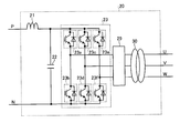
- FIG. 2 is a diagram showing an example of the configuration of the inverter according to the present embodiment.
- the inverter 50 shown in FIG. 2 includes an input filter consisting of a reactor 51 and a filter capacitor 52, an inverter circuit 53 consisting of a bridge circuit consisting of semiconductor switching elements 53a to 53f, and an input voltage monitoring unit 59a and a protection operation unit 59b. And an inverter control unit 59 including the above.
- the power storage element 60 is designed on an assumption that an electric car, which is a 10-car commuter train, is moved about several kilometers to the nearest station in an emergency, and has a storage power of about 100 kWh. Further, by adjusting the number of series of power storage cells 61, the voltage between the +/- terminals of power storage element 60 enables inverter 50 to operate in one pulse mode in the vicinity of the cruising speed in emergency travel. To adjust.
- the auxiliary power supply device 20 takes in the DC power output from the current collector 2 or the DCDC converter 40 through the input filter, and converts the DC power into AC power by the inverter circuit 23. After the switching ripple is removed by the AC filter 29, the converted AC power is isolated by the transformer 30, adjusted to a predetermined voltage (generally about AC 400 V), and the terminal UVW to the load 31 It is output.
- a predetermined voltage generally about AC 400 V
- the modulation factor of the inverter circuit 23 is decreased to control to keep the voltage on the input side (primary side) of the transformer 30 constant.
- the voltage on the input side (primary side) of the transformer 30 is about 600 V, and the voltage on the output side (secondary side) is about 400 V.
- the modulation factor of the inverter circuit 23 reaches its maximum value, and can not be increased further, so the output voltage of the inverter circuit 23 decreases in proportion to the decrease of the input voltage. That is, the voltage on the input side (primary side) of the transformer 30 can not be maintained at the prescribed value (about 600 V in the above example), and the output voltage to the load 31 is also maintained at the prescribed value (about 400 V in the above example) become unable. As a result, a protection function (not shown) operates to stop the auxiliary power supply 20.
- the voltage on the input side (primary side) of the transformer 30 is a low voltage, for example 500 V
- the modulation factor of the inverter circuit 23 needs to have a margin from the upper limit.
- the voltage on the input side (primary side) of the transformer 30 is set low, the current value increases to obtain the same power, and the volume, weight, and cost of the semiconductor switching elements 23a to 23f and the transformer 30 increase.
- the shutdown of the auxiliary power supply 20 can be avoided without considering such a special design.
- the open / close switch 10 is installed between the connection portion of the auxiliary power supply 20 and the DCDC converter 40 and the current collector 2, and can disconnect the auxiliary power supply 20 and the DCDC converter 40 from the current collector 2.
- the state of the open / close switch 10 is input to the link control unit 200.
- the link control unit 200 starts the DCDC converter 40, boosts the voltage of the power storage element 60, and starts the operation of supplying power to the auxiliary power supply 20, on condition that the open / close switch 10 is opened. In this way, it is possible to prevent the voltage boosted by DCDC converter 40 from flowing into overhead wire 1 through current collector 2. Therefore, if there is a failure point such as a short circuit in overhead wire 1, DCDC converter 40 It is possible to avoid a situation where the boosted voltage is applied to the failure point and the damage is expanded.
- the inverter 50 includes an input voltage monitoring unit 59 a that monitors an input voltage (voltage of the filter capacitor 52) using the voltage detection unit 54. Moreover, the inverter 50 has the protection operation part 59b which stops the inverter 50, when an input voltage deviates from a predetermined
- the input voltage monitoring unit 59a sets the prescribed range to about 1000 V to 1900 V when the nominal voltage of the overhead wire 1 is 1500 V.
- the electric vehicle When the control signal HC input from the outside is on, the electric vehicle receives power from the overhead wire 1 and determines that it can not travel (emergency), and the open / close switch is controlled by the control signals C1 to C3. 10 is turned off, the circuit changeover switch 70 is connected to the B side, and the DCDC converter 40 is operated in a voltage control mode in which the voltage of the filter capacitor 42 is controlled to match a predetermined command value. The operation of the DCDC converter 40 starts on the condition that the open / close switch 10 is turned off. Further, based on the control signal C4, the setting change of the protection setting value regarding the input voltage inside the inverter 50 is performed.
- FIG. 6 shows the change of the pulse mode when the rated (nominal) voltage (1500 V) of the overhead wire 1 is applied to the inverter 50. Furthermore, the state of the change of the pulse mode when the terminal voltage (600 V) of the power storage element 60 is applied to the inverter 50 is shown.
- the inverter 50 switches in the multi-pulse PWM mode. In this case, as described above, the inverter 50 may overheat due to lack of cooling capacity. In order to avoid this, the output voltage of the inverter 50 is changed according to the temperature of the semiconductor switching elements 53a to 53f constituting the inverter 50, and control is performed so that the inverter 50 can be operated in one pulse mode. It is further preferable that the configuration be performed.
- the output voltage of the inverter 50 is increased until the inverter 50 performs switching operation in the one-pulse mode.
Abstract
Description
2 集電装置
3 車輪
4 レール
10 開閉スイッチ(開閉部)
11 集電状態検出部
20 補助電源装置
21,41,45,51 リアクトル
22,42,52 フィルタコンデンサ
23,53 インバータ回路
23a,23b,23c,23d,23e,23f,43a,43b,53a,53b,53c,53d,53e,53f 半導体スイッチング素子
29 交流フィルタ
30 トランス
31 負荷
40 DCDCコンバータ
43 スイッチング回路
54 電圧検出部
59a 入力電圧監視部
47 電流検出器
48 DCDCコンバータ制御部
50 インバータ
59 インバータ制御部
59b 保護動作部
60 電力貯蔵素子
70 回路切替スイッチ(回路切替部)
71 電動機
200 連係制御部
C1,C2,C3,C4,HC 制御信号 1
11 current collection
71
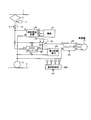
図1は、本実施の形態にかかる電気車の推進制御装置の構成例を示す図である。図1に示す電気車の推進制御装置は、主たる構成部として、補助電源装置20、負荷31、DCDCコンバータ40、回路切替部である回路切替スイッチ70、電力貯蔵素子60、インバータ50、および電動機71を有して構成されている。また、架線1と集電装置2との接続状態、または集電装置2の状態を検出する集電状態検出部11と、架線1と電気車の推進制御装置の電力系統を切り離す開閉部である開閉スイッチ10とを有している。 Embodiment.
FIG. 1 is a view showing a configuration example of a propulsion control device for an electric vehicle according to the present embodiment. The propulsion control apparatus for an electric vehicle shown in FIG. 1 includes, as main components, an auxiliary
Claims (26)
- 直流電圧を交流電圧に変換するインバータと、電力貯蔵素子と前記電力貯蔵素子に接続されるDCDCコンバータとを備えた電気車の推進制御装置において、
外部電源から集電装置を介して供給される電力と前記電力貯蔵素子から供給される電力のいずれか一方を選択し前記インバータに出力する回路切替部と、
少なくとも、前記DCDCコンバータ、および前記回路切替部を連係して制御する連係制御部と、
を備え、
前記連係制御部は、
電気車が外部電源から受電して走行する場合と前記電力貯蔵素子からの電力で走行する場合とのそれぞれに応じて、少なくとも、前記DCDCコンバータおよび前記回路切替部に、それぞれ制御信号を入力し、かつ、それらを連係して制御すること、
を特徴とする電気車の推進制御装置。 In a propulsion control apparatus of an electric vehicle, comprising: an inverter for converting a DC voltage to an AC voltage; a power storage element; and a DCDC converter connected to the power storage element,
A circuit switching unit that selects one of power supplied from an external power source via a current collector and power supplied from the power storage element, and outputs the selected power to the inverter;
At least a DC / DC converter and an association control unit for controlling the circuit switching unit in cooperation;
Equipped with
The linkage control unit
A control signal is input to at least the DCDC converter and the circuit switching unit according to the case where the electric vehicle travels by receiving power from the external power source and the case where the vehicle travels with the power from the power storage element, And controlling them in coordination;
A propulsion control device for an electric vehicle characterized by - 前記インバータの出力電圧基本波半周期中に含まれるパルス数が所定の数以下となるときの車速は、前記電力貯蔵素子から電力を供給される場合の方が、前記外部電源から電力を供給される場合に比して低いことを特徴する請求項1に記載の電気車の推進制御装置。 The vehicle speed when the number of pulses included in the output voltage fundamental wave half cycle of the inverter is equal to or less than a predetermined number is supplied with power from the external power supply when power is supplied from the power storage element. The propulsion control apparatus for an electric vehicle according to claim 1, characterized in that it is lower than in the case of
- 前記電力貯蔵素子の端子間の電圧は、前記電力貯蔵素子からの電力により走行するときの巡航速度において、前記インバータが1パルスモードで動作可能となるように調整された値であることを特徴とする請求項1に記載の電気車の推進制御装置。 The voltage between the terminals of the power storage element is a value adjusted such that the inverter can operate in one pulse mode at a cruising speed when traveling with power from the power storage element. The propulsion control apparatus of the electric vehicle according to claim 1.
- 前記電力貯蔵素子の端子の電圧値は、前記外部電源の定格電圧の20~50%の値であることを特徴とする請求項1に記載の電気車の推進制御装置。 The propulsion control apparatus of an electric vehicle according to claim 1, wherein the voltage value of the terminal of the power storage element is 20 to 50% of the rated voltage of the external power supply.
- 前記インバータの出力電圧基本波半周期中に含まれるパルス数に関する所定の数は、1であることを特徴とする請求項2に記載の電気車の推進制御装置。 The propulsion control apparatus for an electric vehicle according to claim 2, wherein the predetermined number of pulses included in the output voltage fundamental wave half cycle of the inverter is one.
- 前記電気車に搭載される負荷に電力を供給する補助電源装置を備え、
前記DCDCコンバータは、前記外部電源からの電力の受電が不可能となった場合、前記電力貯蔵素子の電圧を、前記補助電源装置が通常前記外部電源から受電する電圧程度まで昇圧し、前記補助電源装置に供給することを特徴とする請求項1~5のいずれか1つに記載の電気車の推進制御装置。 An auxiliary power unit for supplying power to a load mounted on the electric vehicle;
When the DCDC converter can not receive power from the external power supply, the DCDC converter boosts the voltage of the power storage element to about the voltage that the auxiliary power supply normally receives power from the external power supply, and the auxiliary power supply The propulsion control apparatus for an electric vehicle according to any one of claims 1 to 5, wherein the apparatus is supplied. - 前記外部電源と前記集電装置との接続状態を検出する集電状態検出部を備え、
前記外部電源と前記集電装置との接続が断たれたことを前記集電状態検出部が検出したことを条件として、前記DCDCコンバータは、昇圧運転を行うことを特徴とする請求項1~6のいずれか1つに記載の電気車の推進制御装置。 A current collection state detection unit configured to detect a connection state of the external power supply and the current collection device;
The DCDC converter performs a step-up operation on condition that the current collection state detection unit detects that the connection between the external power supply and the current collection device is disconnected. The propulsion control apparatus of the electric vehicle according to any one of the above. - 前記補助電源装置および前記DCDCコンバータの接続部と前記集電装置との間に設置され、前記補助電源装置および前記DCDCコンバータを前記集電装置から切り離す開閉部を備え、
前記開閉部が開放されたことを条件として、前記DCDCコンバータは、昇圧運転を行うことを特徴とする請求項1~6のいずれか1つに記載の電気車の推進制御装置。 The switch is installed between the connection unit of the auxiliary power supply and the DCDC converter and the current collector, and the switch is configured to separate the auxiliary power supply and the DCDC converter from the current collector.
The propulsion control apparatus for an electric vehicle according to any one of claims 1 to 6, wherein the DCDC converter performs a boost operation on condition that the open / close unit is opened. - 前記連係制御部は、
前記外部電源からの受電による電気車の走行が可能と判断した場合には、前記インバータが前記外部電源と直結されるように前記回路切替部を制御するとともに、前記DCDCコンバータが前記電力貯蔵素子に前記外部電源の電力を充電する動作を行うように制御し、
前記外部電源からの受電による電気車の走行が不可能と判断した場合、前記インバータを前記電力貯蔵素子に直結されるように前記回路切替部を制御するとともに、前記DCDCコンバータが電気車に搭載され負荷に電力を供給する補助電源装置に前記電力貯蔵素子の電力を供給する動作を行うように制御することを特徴とする請求項1に記載の電気車の推進制御装置。 The linkage control unit
When it is determined that traveling of the electric vehicle by receiving power from the external power source is possible, the inverter controls the circuit switching unit so as to be directly connected to the external power source, and the DCDC converter serves as the power storage element. Control to charge the power of the external power supply,
When it is determined that traveling of the electric vehicle by receiving power from the external power source is not possible, the circuit switching unit is controlled such that the inverter is directly coupled to the power storage element, and the DCDC converter is mounted on the electric vehicle The propulsion control apparatus for an electric vehicle according to claim 1, wherein an operation is performed to supply power of the power storage element to an auxiliary power supply that supplies power to a load. - 前記補助電源装置の給電範囲にある電気車の空調装置に対して、前記連係制御部からの制御信号を出力する構成とされており、
前記連係制御部は、
電気車が前記電力貯蔵素子からの電力で走行する場合、前記空調装置への停止指令を出力して前記空調装置を停止させることを特徴とする請求項1に記載の電気車の推進制御装置。 The control signal from the linkage control unit is output to the air conditioner of the electric vehicle in the power supply range of the auxiliary power supply device,
The linkage control unit
The propulsion control device for an electric vehicle according to claim 1, wherein when the electric vehicle travels with power from the electric power storage element, a stop command to the air conditioner is output to stop the air conditioner. - 前記補助電源装置の給電範囲にある電気車に搭載されている空調装置に対して、前記連係制御部からの制御信号を出力する構成とされており、
前記連係制御部は、
電気車が前記電力貯蔵素子からの電力で走行する場合、前記空調装置に内蔵されている冷媒圧縮用コンプレッサの停止指令を出力し、電気車車内に搭載される送風ファンの運転を継続させることを特徴とする請求項1に記載の電気車の推進制御装置。 The control signal from the linkage control unit is output to an air conditioner mounted on an electric vehicle in a power supply range of the auxiliary power supply device,
The linkage control unit
When the electric car travels with the electric power from the electric power storage element, the stop command of the refrigerant compression compressor built in the air conditioner is outputted, and the operation of the blower fan mounted in the electric car is continued. The propulsion control apparatus of the electric vehicle of Claim 1 characterized by the above-mentioned. - 前記DCDCコンバータは、
前記外部電源に接続されたリアクトルおよびフィルタコンデンサからなる入力フィルタ回路と、前記フィルタコンデンサの直流電圧を任意の直流電圧に変換して出力するスイッチング回路とを有し、
前記スイッチング回路は、
前記フィルタコンデンサに並列接続された上アーム側スイッチング素子と下アーム側スイッチング素子とから構成され、前記上アーム側スイッチング素子と前記下アーム側スイッチング素子との接続点にリアクトルが接続された構成である場合、
前記DCDCコンバータの前記フィルタコンデンサ電圧を所定の値に制御する電圧制御モードと、前記DCDCコンバータの前記リアクトル電流を所定の値に制御する電流制御モードとを有することを特徴とする請求項1に記載の電気車の推進制御装置。 The DCDC converter is
It has an input filter circuit consisting of a reactor and a filter capacitor connected to the external power supply, and a switching circuit which converts the DC voltage of the filter capacitor into an arbitrary DC voltage and outputs it.
The switching circuit is
It is comprised from the upper arm side switching element connected in parallel with the said filter capacitor, and a lower arm side switching element, and it is the structure by which the reactor was connected to the connection point of the said upper arm side switching element and the said lower arm side switching element. If
The voltage control mode for controlling the filter capacitor voltage of the DCDC converter to a predetermined value, and the current control mode for controlling the reactor current of the DCDC converter to a predetermined value are characterized in that Of electric vehicle propulsion control device. - 前記DCDCコンバータは、電気車が外部電源から受電して走行する場合と、前記電力貯蔵素子からの電力で走行する場合とで、前記制御モードを切り替えて運転することを特徴とする請求項12に記載の電気車の推進制御装置。 The DCDC converter operates by switching the control mode between when the electric vehicle travels by receiving power from an external power source and when traveling with the power from the power storage element. The propulsion control apparatus of the electric vehicle as described.
- 前記DCDCコンバータは、前記フィルタコンデンサの電圧を、前記補助電源装置の入力電圧の許容下限値付近に制御することを特徴とする請求項6に記載の電気車の推進制御装置。 The propulsion control apparatus for an electric vehicle according to claim 6, wherein the DCDC converter controls the voltage of the filter capacitor to be in the vicinity of an allowable lower limit value of an input voltage of the auxiliary power supply device.
- 前記DCDCコンバータは、
前記電力貯蔵素子の貯蔵電力量に関する目標値を有し、前記電力貯蔵素子への充放電を行って貯蔵電力量を前記目標値に制御するものであって、
前記貯蔵電力量の目標値を少なくとも時刻に応じて変化させることを特徴とする請求項1に記載の電気車の推進制御装置。 The DCDC converter is
It has a target value related to the storage power amount of the power storage element, and performs charging / discharging to the power storage element to control the storage power amount to the target value,
The propulsion control apparatus of the electric vehicle according to claim 1, wherein the target value of the stored power amount is changed according to at least time. - 前記DCDCコンバータは、
前記電力貯蔵素子の貯蔵電力量に関する目標値を有し、前記電力貯蔵素子への充放電を行って前記貯蔵電力量を前記目標値に制御するものであって、
前記貯蔵電力量の目標値を前記連係制御部からの制御信号に応じて変化させることを特徴とする請求項1に記載の電気車の推進制御装置。 The DCDC converter is
It has a target value related to the stored power amount of the power storage element, and performs charging and discharging of the power storage element to control the stored power amount to the target value.
The propulsion control apparatus for an electric vehicle according to claim 1, wherein the target value of the stored power amount is changed according to a control signal from the linkage control unit. - 前記DCDCコンバータは、
前記電力貯蔵素子の貯蔵電力量に関する目標値を有し、前記電力貯蔵素子への充放電を行って前記貯蔵電力量を前記目標値に制御するものであって、
前記インバータの動作状態に応じて、前記貯蔵電力量の目標値を低下させることを特徴とする請求項1に記載の電気車の推進制御装置。 The DCDC converter is
It has a target value related to the stored power amount of the power storage element, and performs charging and discharging of the power storage element to control the stored power amount to the target value.
The propulsion control apparatus of the electric vehicle according to claim 1, wherein the target value of the stored power amount is decreased according to the operating state of the inverter. - 前記DCDCコンバータの出力容量は、前記補助電源装置の出力容量以下であることを特徴とする請求項6に記載の電気車の推進制御装置。 The propulsion control apparatus of an electric vehicle according to claim 6, wherein an output capacity of the DCDC converter is equal to or less than an output capacity of the auxiliary power supply apparatus.
- 前記インバータは、
少なくとも前記インバータの入力電圧を監視する入力電圧監視部を有し、前記入力電圧が所定の範囲から逸脱する場合、前記インバータを停止させる保護動作部を備えたものであって、
前記入力電圧監視部は、
電気車が外部電源から受電して走行する場合と、前記電力貯蔵素子からの電力で走行する場合とで、入力電圧に関する前記所定の範囲を切り替えることを特徴とする請求項1に記載の電気車の推進制御装置。 The inverter is
At least an input voltage monitoring unit monitoring an input voltage of the inverter, and a protection operation unit stopping the inverter when the input voltage deviates from a predetermined range,
The input voltage monitoring unit
The electric vehicle according to claim 1, wherein the predetermined range regarding the input voltage is switched between when the electric vehicle travels by receiving power from an external power source and when traveling with power from the power storage element. Propulsion control device. - 前記インバータは、インバータを構成する半導体スイッチング素子の温度に応じて、インバータの出力電圧を変化させる所定の動作を行うことを特徴とする請求項1に記載の電気車の推進制御装置。 The propulsion control apparatus for an electric vehicle according to claim 1, wherein the inverter performs a predetermined operation of changing an output voltage of the inverter according to a temperature of a semiconductor switching element constituting the inverter.
- 前記インバータは、インバータを構成する半導体スイッチング素子の温度が所定の値以上である場合、インバータの出力電圧を増加させる所定の動作を行うことを特徴とする請求項20に記載の電気車の推進制御装置。 21. The propulsion control of an electric vehicle according to claim 20, wherein the inverter performs a predetermined operation of increasing the output voltage of the inverter when the temperature of the semiconductor switching element constituting the inverter is equal to or higher than a predetermined value. apparatus.
- 前記インバータは、インバータを構成する半導体スイッチング素子の温度が所定の値以上である場合、インバータの出力電圧を1パルスモードでのスイッチング動作となるまで増加させる所定の動作を行うことを特徴とする請求項21に記載の電気車の推進制御装置。 The inverter is characterized in that, when the temperature of the semiconductor switching element constituting the inverter is equal to or higher than a predetermined value, the inverter performs a predetermined operation to increase the output voltage of the inverter until the switching operation in one pulse mode is achieved. The propulsion control apparatus of the electric vehicle of Claim 21.
- 前記所定の動作は、前記インバータの負荷である電動機の励磁電流を増加させることを特徴とする請求項20~22のいずれか1つに記載の電気車の推進制御装置。 The propulsion control apparatus for an electric vehicle according to any one of claims 20 to 22, wherein the predetermined operation increases an excitation current of a motor which is a load of the inverter.
- 前記DCDCコンバータは、前記電圧制御モードおよび前記電流制御モードを前記連係制御部からの前記制御信号に応じて切替えることを特徴とする請求項12に記載の電気車の推進制御装置。 The propulsion control apparatus of an electric vehicle according to claim 12, wherein the DCDC converter switches the voltage control mode and the current control mode in accordance with the control signal from the linkage control unit.
- 前記インバータは、前記入力電圧に関する所定の範囲を前記連係制御部からの前記制御信号に応じて切替えることを特徴とする請求項19に記載の電気車の推進制御装置。 20. The propulsion control apparatus for an electric vehicle according to claim 19, wherein the inverter switches a predetermined range related to the input voltage according to the control signal from the linkage control unit.
- 前記DCDCコンバータは、前記電力貯蔵素子の貯蔵電力量に関する目標値を有し、前記電力貯蔵素子への充放電を行って前記貯蔵電力量を前記目標値に制御するものであって、前記貯蔵電力量の目標値を外部からの制御信号に応じて変化させることを特徴とする請求項1に記載の電気車の推進制御装置。 The DCDC converter has a target value related to the stored power amount of the power storage element, and performs charging and discharging of the power storage element to control the stored power amount to the target value, and the stored power The propulsion control apparatus for an electric vehicle according to claim 1, wherein the target value of the quantity is changed according to an external control signal.
Priority Applications (8)
| Application Number | Priority Date | Filing Date | Title |
|---|---|---|---|
| JP2009525843A JP4558096B2 (en) | 2008-10-23 | 2008-10-23 | Electric vehicle propulsion control device |
| CA2740979A CA2740979C (en) | 2008-10-23 | 2008-10-23 | Propulsion control apparatus for electric vehicle |
| US13/062,808 US8615341B2 (en) | 2008-10-23 | 2008-10-23 | Propulsion control apparatus for electric vehicle |
| KR1020117007516A KR101260139B1 (en) | 2008-10-23 | 2008-10-23 | Propulsion control device for electric car |
| CN200880131823.0A CN102196938B (en) | 2008-10-23 | 2008-10-23 | Propulsion control device for electric car |
| EP08877550.7A EP2340957B1 (en) | 2008-10-23 | 2008-10-23 | Propulsion control device for electric car |
| RU2011120333/11A RU2478490C2 (en) | 2008-10-23 | 2008-10-23 | Device to control electrified transport facility power plant |
| PCT/JP2008/069232 WO2010046984A1 (en) | 2008-10-23 | 2008-10-23 | Propulsion control device for electric car |
Applications Claiming Priority (1)
| Application Number | Priority Date | Filing Date | Title |
|---|---|---|---|
| PCT/JP2008/069232 WO2010046984A1 (en) | 2008-10-23 | 2008-10-23 | Propulsion control device for electric car |
Publications (1)
| Publication Number | Publication Date |
|---|---|
| WO2010046984A1 true WO2010046984A1 (en) | 2010-04-29 |
Family
ID=42119045
Family Applications (1)
| Application Number | Title | Priority Date | Filing Date |
|---|---|---|---|
| PCT/JP2008/069232 WO2010046984A1 (en) | 2008-10-23 | 2008-10-23 | Propulsion control device for electric car |
Country Status (8)
| Country | Link |
|---|---|
| US (1) | US8615341B2 (en) |
| EP (1) | EP2340957B1 (en) |
| JP (1) | JP4558096B2 (en) |
| KR (1) | KR101260139B1 (en) |
| CN (1) | CN102196938B (en) |
| CA (1) | CA2740979C (en) |
| RU (1) | RU2478490C2 (en) |
| WO (1) | WO2010046984A1 (en) |
Cited By (8)
| Publication number | Priority date | Publication date | Assignee | Title |
|---|---|---|---|---|
| CN103115647A (en) * | 2013-02-01 | 2013-05-22 | 赵乎 | Monitoring system for rail transit bow net operating condition |
| JP2013198195A (en) * | 2012-03-16 | 2013-09-30 | Toshiba Corp | Electric vehicle control device |
| CN103438924A (en) * | 2013-08-23 | 2013-12-11 | 天津市三特电子有限公司 | Electric locomotive pantograph net online detection system and detection method |
| CN103733472A (en) * | 2011-02-22 | 2014-04-16 | 伟创力国际Kft | Voltage stabilization apparatus |
| EP2647521A4 (en) * | 2010-12-01 | 2017-05-24 | Mitsubishi Electric Corporation | Control device for electric vehicle |
| JP2019186985A (en) * | 2018-04-02 | 2019-10-24 | 株式会社東芝 | Storage battery system and electric vehicle control system |
| JP2021132480A (en) * | 2020-02-20 | 2021-09-09 | 株式会社日立製作所 | Motor system and discharge detection method |
| JP7472462B2 (en) | 2019-10-11 | 2024-04-23 | オムロン株式会社 | Servo DC power supply system and motor control device |
Families Citing this family (48)
| Publication number | Priority date | Publication date | Assignee | Title |
|---|---|---|---|---|
| DE102009008549A1 (en) * | 2009-02-12 | 2010-08-19 | Bombardier Transportation Gmbh | Arrangement for operating loads in a rail vehicle with electrical energy, optionally from a power supply network or from a motor-generator combination |
| US8649923B2 (en) * | 2010-01-12 | 2014-02-11 | Ford Global Technologies, Llc | E-drive PWM frequency strategy |
| WO2012014324A1 (en) * | 2010-07-30 | 2012-02-02 | 三菱電機株式会社 | Electric vehicle propulsion control device, and railway vehicle system |
| CN103283135A (en) * | 2010-12-27 | 2013-09-04 | 株式会社日立制作所 | Electric power converter |
| KR101231848B1 (en) * | 2011-02-10 | 2013-02-08 | 한국과학기술원 | Apparatus for Providing Power for Electric Vehicle and Driving Method Thereof |
| KR101262973B1 (en) * | 2011-05-24 | 2013-05-08 | 기아자동차주식회사 | System for cotroling emergency travel of hybrid electric vehicle and method thereof |
| KR101591218B1 (en) * | 2011-12-12 | 2016-02-02 | 미쓰비시덴키 가부시키가이샤 | Electric vehicle drive system |
| KR20140116514A (en) * | 2012-02-28 | 2014-10-02 | 미쓰비시덴키 가부시키가이샤 | Onboard information display system and power supply method |
| KR101300380B1 (en) * | 2012-03-02 | 2013-08-29 | 엘에스산전 주식회사 | Method for stabilizing inverter output current |
| US9296300B2 (en) * | 2012-04-13 | 2016-03-29 | General Electric Company | Method and system for powering a vehicle |
| KR101627960B1 (en) * | 2012-06-07 | 2016-06-07 | 미쓰비시덴키 가부시키가이샤 | Electric vehicle control device |
| AT513095B1 (en) * | 2012-07-04 | 2015-06-15 | Siemens Ag Oesterreich | Electrically powered rail vehicle |
| US9008879B2 (en) * | 2012-07-05 | 2015-04-14 | General Electric Company | System and method for operating a hybrid vehicle system |
| JP6461460B2 (en) * | 2013-08-29 | 2019-01-30 | 株式会社東芝 | Power converter, emergency travel system, and railway vehicle |
| DE102013226356A1 (en) | 2013-10-02 | 2015-04-02 | Scania Cv Ab | vehicle |
| CN104129317B (en) * | 2013-12-23 | 2016-08-31 | 武汉英康汇通电气有限公司 | I.e. fill formula trolleybus control method |
| US9834098B2 (en) * | 2014-01-30 | 2017-12-05 | General Electric Company | Vehicle propulsion system with multi-channel DC bus and method of manufacturing same |
| JP6259778B2 (en) * | 2014-02-13 | 2018-01-10 | 株式会社日立製作所 | Railway vehicle drive system |
| US10050548B2 (en) * | 2014-09-29 | 2018-08-14 | The Boeing Company | No-break power transfer |
| SE538656C2 (en) * | 2014-10-30 | 2016-10-11 | Scania Cv Ab | Method and system for switching from a first power supply path to a second power supply path |
| DE102015102410A1 (en) * | 2015-02-20 | 2016-08-25 | Vossloh Kiepe Gmbh | Battery assembly for a vehicle |
| JP6642974B2 (en) * | 2015-03-27 | 2020-02-12 | 株式会社東芝 | Electric car control device |
| JP6397799B2 (en) * | 2015-06-01 | 2018-09-26 | 株式会社日立製作所 | Auxiliary power supply system and operation method thereof |
| CN105398353B (en) * | 2015-10-23 | 2019-01-08 | 惠州市亿能电子有限公司 | A kind of rail transit locomotive power-supply system and its control method |
| US10300791B2 (en) * | 2015-12-18 | 2019-05-28 | Ge Global Sourcing Llc | Trolley interfacing device having a pre-charging unit |
| KR20170114579A (en) * | 2016-04-05 | 2017-10-16 | 주식회사 만도 | Voltage control method and system thereof |
| JP6815762B2 (en) * | 2016-06-17 | 2021-01-20 | 東海旅客鉄道株式会社 | Power conversion system |
| FR3053937B1 (en) * | 2016-07-12 | 2018-07-20 | Sncf Mobilites | POWER SUPPLY SYSTEM FOR A RAILWAY VEHICLE AND RAILWAY VEHICLE COMPRISING SUCH A SYSTEM |
| JP2018014822A (en) * | 2016-07-20 | 2018-01-25 | 株式会社リコー | Image forming apparatus, power supply method, and program |
| JP6829069B2 (en) * | 2016-12-28 | 2021-02-10 | 株式会社東芝 | Circuit system for railroad vehicles |
| FR3062823B1 (en) * | 2017-02-14 | 2021-04-23 | Alstom Transp Tech | ELECTRICAL ENERGY MANAGEMENT PROCESS IN A RAIL VEHICLE, CORRESPONDING ENERGY MANAGEMENT SYSTEM AND CORRESPONDING RAIL VEHICLE |
| CN110603168B (en) * | 2017-06-13 | 2023-03-31 | 株式会社东芝 | Railway vehicle |
| CN107618379B (en) * | 2017-09-20 | 2021-04-02 | 株洲时代电子技术有限公司 | Switching control method for hybrid power source of railway engineering machinery |
| WO2019064817A1 (en) * | 2017-09-29 | 2019-04-04 | 本田技研工業株式会社 | Vehicle control device |
| KR102106911B1 (en) * | 2017-11-24 | 2020-05-06 | 엘지전자 주식회사 | Power converting apparatus and home appliance including the same |
| CN110014864B (en) * | 2017-12-20 | 2021-02-09 | 中车长春轨道客车股份有限公司 | Train traction rescue method and system |
| JP6922846B2 (en) * | 2018-05-24 | 2021-08-18 | 株式会社オートネットワーク技術研究所 | In-vehicle power supply |
| FR3082790B1 (en) * | 2018-06-26 | 2020-06-19 | Sncf Mobilites | METHOD FOR REGULATING THE INSTANTANEOUS ELECTRIC POWER PROVIDED TO A RAIL VEHICLE BY AN EXTERNAL SOURCE |
| DE102018212463A1 (en) * | 2018-07-26 | 2020-01-30 | Continental Automotive Gmbh | Voltage variation and phase control in the DC link |
| CN108859773B (en) * | 2018-08-03 | 2024-02-02 | 陕西通运专用汽车集团有限公司 | Pure electric mine car transportation system |
| WO2020184484A1 (en) * | 2019-03-08 | 2020-09-17 | 株式会社日立パワーソリューションズ | Electric moving body and electric moving body charging system |
| DE102019211230A1 (en) * | 2019-07-29 | 2021-02-04 | Scania Cv Ab | vehicle |
| JP7409136B2 (en) * | 2020-02-13 | 2024-01-09 | 株式会社デンソー | Power converter control circuit |
| US11929632B2 (en) | 2021-01-27 | 2024-03-12 | Livewire Ev, Llc | On-board charger system with integrated auxiliary power supply |
| DE102022125116A1 (en) | 2021-11-12 | 2023-05-17 | Hofer Powertrain Innovation Gmbh | Traction energy supply method, in particular using a power supply system for motor vehicles, preferably for commercial vehicles for electrically operated heavy traffic |
| DE202021106215U1 (en) | 2021-11-12 | 2023-02-14 | Hofer Powertrain Innovation Gmbh | Electrical power supply system for vehicles, in particular for heavy goods vehicles, with overhead line tap |
| WO2023084053A1 (en) | 2021-11-12 | 2023-05-19 | Hofer Powertrain Innovation Gmbh | Traction energy supply method, in particular using a energy supply system for motor vehicles, preferably for utility vehicles for electrically operated heavy goods transport |
| DE202021106214U1 (en) | 2021-11-12 | 2023-02-14 | Hofer Powertrain Innovation Gmbh | Trucks with an electric drive, in particular in an overhead line infrastructure that is present in some sections |
Citations (3)
| Publication number | Priority date | Publication date | Assignee | Title |
|---|---|---|---|---|
| JPH0270201A (en) * | 1988-09-03 | 1990-03-09 | Fuji Electric Co Ltd | Auxiliary power source equipment for vehicle |
| JP2006014395A (en) | 2004-06-22 | 2006-01-12 | Toshiba Corp | Controller of electric vehicle |
| WO2008018131A1 (en) * | 2006-08-09 | 2008-02-14 | Mitsubishi Electric Corporation | Power converter and controller using such power converter for electric rolling stock |
Family Cites Families (24)
| Publication number | Priority date | Publication date | Assignee | Title |
|---|---|---|---|---|
| JP2555038B2 (en) | 1986-11-05 | 1996-11-20 | 株式会社日立製作所 | Induction motor type electric vehicle controller |
| RU2013230C1 (en) | 1991-03-29 | 1994-05-30 | Петербургский институт инженеров железнодорожного транспорта | Unit for sample-data control of speed of vehicle traction motor |
| JP2765315B2 (en) * | 1991-11-18 | 1998-06-11 | 株式会社日立製作所 | Power conversion device and control device for electric vehicle using the same |
| US5399909A (en) * | 1993-03-08 | 1995-03-21 | Impulse Nc, Inc. | Secondary electrical power supply |
| US5491622A (en) * | 1994-01-07 | 1996-02-13 | Delco Electronics Corp. | Power converter with emergency operating mode for three phase induction motors |
| JP3338328B2 (en) * | 1997-04-21 | 2002-10-28 | 株式会社日立製作所 | Vehicle power supply |
| US6122181A (en) * | 1998-05-21 | 2000-09-19 | Exide Electronics Corporation | Systems and methods for producing standby uninterruptible power for AC loads using rectified AC and battery |
| DE19921450C5 (en) * | 1999-05-08 | 2006-08-03 | Daimlerchrysler Ag | Electric vehicle drive |
| JP3808701B2 (en) | 2000-12-20 | 2006-08-16 | 株式会社東芝 | Vehicle power supply device and control device therefor |
| US6612245B2 (en) | 2001-03-27 | 2003-09-02 | General Electric Company | Locomotive energy tender |
| US6615118B2 (en) * | 2001-03-27 | 2003-09-02 | General Electric Company | Hybrid energy power management system and method |
| US20060005736A1 (en) * | 2001-03-27 | 2006-01-12 | General Electric Company | Hybrid energy off highway vehicle electric power management system and method |
| JP2003102181A (en) * | 2001-09-25 | 2003-04-04 | Toyota Motor Corp | System and method for electric power supply |
| EP1480330A3 (en) * | 2003-05-22 | 2007-09-26 | Jtekt Corporation | Apparatus and method for controlling a motor |
| JP4422567B2 (en) * | 2004-06-30 | 2010-02-24 | 株式会社日立製作所 | Motor drive device, electric actuator, and electric power steering device |
| KR100649508B1 (en) * | 2005-02-02 | 2006-11-27 | 권오영 | Hybrid power supply system |
| JP4568169B2 (en) * | 2005-05-18 | 2010-10-27 | 株式会社東芝 | Electric vehicle control device |
| CN100574090C (en) * | 2005-12-26 | 2009-12-23 | 日产自动车株式会社 | Electric power conversion apparatus |
| WO2008004294A1 (en) * | 2006-07-06 | 2008-01-10 | Mitsubishi Electric Corporation | Induction motor vector control device, induction motor vector control method, and induction motor drive control device |
| US8427004B2 (en) * | 2006-07-20 | 2013-04-23 | Mitsubishi Electric Corporation | Electric-vehicle controller and power storage unit shutoff switch |
| KR100906909B1 (en) * | 2006-12-12 | 2009-07-08 | 현대자동차주식회사 | Power down control method of fuel cell hybrid electric vehicle |
| KR100837920B1 (en) * | 2007-02-06 | 2008-06-17 | 현대자동차주식회사 | Control method for a hybrid vehicle |
| US8180544B2 (en) * | 2007-04-25 | 2012-05-15 | General Electric Company | System and method for optimizing a braking schedule of a powered system traveling along a route |
| US8112191B2 (en) * | 2007-04-25 | 2012-02-07 | General Electric Company | System and method for monitoring the effectiveness of a brake function in a powered system |
-
2008
- 2008-10-23 RU RU2011120333/11A patent/RU2478490C2/en not_active IP Right Cessation
- 2008-10-23 JP JP2009525843A patent/JP4558096B2/en active Active
- 2008-10-23 US US13/062,808 patent/US8615341B2/en active Active
- 2008-10-23 KR KR1020117007516A patent/KR101260139B1/en not_active IP Right Cessation
- 2008-10-23 CA CA2740979A patent/CA2740979C/en not_active Expired - Fee Related
- 2008-10-23 EP EP08877550.7A patent/EP2340957B1/en not_active Not-in-force
- 2008-10-23 CN CN200880131823.0A patent/CN102196938B/en active Active
- 2008-10-23 WO PCT/JP2008/069232 patent/WO2010046984A1/en active Application Filing
Patent Citations (3)
| Publication number | Priority date | Publication date | Assignee | Title |
|---|---|---|---|---|
| JPH0270201A (en) * | 1988-09-03 | 1990-03-09 | Fuji Electric Co Ltd | Auxiliary power source equipment for vehicle |
| JP2006014395A (en) | 2004-06-22 | 2006-01-12 | Toshiba Corp | Controller of electric vehicle |
| WO2008018131A1 (en) * | 2006-08-09 | 2008-02-14 | Mitsubishi Electric Corporation | Power converter and controller using such power converter for electric rolling stock |
Cited By (10)
| Publication number | Priority date | Publication date | Assignee | Title |
|---|---|---|---|---|
| EP2647521A4 (en) * | 2010-12-01 | 2017-05-24 | Mitsubishi Electric Corporation | Control device for electric vehicle |
| CN103733472A (en) * | 2011-02-22 | 2014-04-16 | 伟创力国际Kft | Voltage stabilization apparatus |
| JP2013198195A (en) * | 2012-03-16 | 2013-09-30 | Toshiba Corp | Electric vehicle control device |
| CN103115647A (en) * | 2013-02-01 | 2013-05-22 | 赵乎 | Monitoring system for rail transit bow net operating condition |
| CN103438924A (en) * | 2013-08-23 | 2013-12-11 | 天津市三特电子有限公司 | Electric locomotive pantograph net online detection system and detection method |
| JP2019186985A (en) * | 2018-04-02 | 2019-10-24 | 株式会社東芝 | Storage battery system and electric vehicle control system |
| JP7030599B2 (en) | 2018-04-02 | 2022-03-07 | 株式会社東芝 | Battery system and electric vehicle control system |
| JP7472462B2 (en) | 2019-10-11 | 2024-04-23 | オムロン株式会社 | Servo DC power supply system and motor control device |
| JP2021132480A (en) * | 2020-02-20 | 2021-09-09 | 株式会社日立製作所 | Motor system and discharge detection method |
| JP7358271B2 (en) | 2020-02-20 | 2023-10-10 | 株式会社日立製作所 | Electric motor system and discharge detection method |
Also Published As
| Publication number | Publication date |
|---|---|
| EP2340957A4 (en) | 2014-08-06 |
| CN102196938B (en) | 2014-04-23 |
| EP2340957A1 (en) | 2011-07-06 |
| CA2740979A1 (en) | 2010-04-29 |
| CN102196938A (en) | 2011-09-21 |
| JPWO2010046984A1 (en) | 2012-03-15 |
| RU2011120333A (en) | 2012-11-27 |
| US8615341B2 (en) | 2013-12-24 |
| US20110166736A1 (en) | 2011-07-07 |
| KR101260139B1 (en) | 2013-05-02 |
| KR20110047274A (en) | 2011-05-06 |
| RU2478490C2 (en) | 2013-04-10 |
| CA2740979C (en) | 2014-09-16 |
| EP2340957B1 (en) | 2018-08-29 |
| JP4558096B2 (en) | 2010-10-06 |
Similar Documents
| Publication | Publication Date | Title |
|---|---|---|
| WO2010046984A1 (en) | Propulsion control device for electric car | |
| JP5558022B2 (en) | Electric vehicle storage control device and storage control method | |
| JP5014518B2 (en) | Electric vehicle propulsion control device and railway vehicle system | |
| US9018792B2 (en) | Arrangement for operating consumers in a rail vehicle with electrical energy, selectively from an energy supply network or from a motor-generator combination | |
| US7451842B2 (en) | Control system for electric motor car | |
| JP4841441B2 (en) | Battery charger for railway vehicles | |
| JP2011004566A (en) | Auxiliary power supply apparatus for electric vehicle | |
| JP5350843B2 (en) | Power supply control device and power supply control method | |
| JP4178728B2 (en) | Power supply equipment for electric vehicles | |
| JP5777669B2 (en) | Electric vehicle control device | |
| JPWO2020075504A1 (en) | How to charge a railroad vehicle drive system and a power storage device in a railroad vehicle | |
| JP2015204665A (en) | Electric power conversion apparatus, and railway vehicle comprising the same | |
| CN112825465B (en) | Converter for railway vehicle shaft end power generation system and shaft end power generation system | |
| CN113162203B (en) | Power supply method for track flash welding | |
| CN114056105A (en) | Rail vehicle traction transmission system and rail vehicle |
Legal Events
| Date | Code | Title | Description |
|---|---|---|---|
| WWE | Wipo information: entry into national phase |
Ref document number: 200880131823.0 Country of ref document: CN |
|
| WWE | Wipo information: entry into national phase |
Ref document number: 2009525843 Country of ref document: JP |
|
| 121 | Ep: the epo has been informed by wipo that ep was designated in this application |
Ref document number: 08877550 Country of ref document: EP Kind code of ref document: A1 |
|
| WWE | Wipo information: entry into national phase |
Ref document number: 13062808 Country of ref document: US |
|
| ENP | Entry into the national phase |
Ref document number: 20117007516 Country of ref document: KR Kind code of ref document: A |
|
| WWE | Wipo information: entry into national phase |
Ref document number: 2008877550 Country of ref document: EP |
|
| WWE | Wipo information: entry into national phase |
Ref document number: 2740979 Country of ref document: CA |
|
| WWE | Wipo information: entry into national phase |
Ref document number: 2708/CHENP/2011 Country of ref document: IN |
|
| NENP | Non-entry into the national phase |
Ref country code: DE |
|
| WWE | Wipo information: entry into national phase |
Ref document number: 2011120333 Country of ref document: RU |