US9985566B2 - Dual three-phase electrical machine and drive with negligible common-mode noise - Google Patents
Dual three-phase electrical machine and drive with negligible common-mode noise Download PDFInfo
- Publication number
- US9985566B2 US9985566B2 US15/131,543 US201615131543A US9985566B2 US 9985566 B2 US9985566 B2 US 9985566B2 US 201615131543 A US201615131543 A US 201615131543A US 9985566 B2 US9985566 B2 US 9985566B2
- Authority
- US
- United States
- Prior art keywords
- windings
- phase
- common
- groups
- dual
- Prior art date
- Legal status (The legal status is an assumption and is not a legal conclusion. Google has not performed a legal analysis and makes no representation as to the accuracy of the status listed.)
- Active
Links
Images


Classifications
-
- H—ELECTRICITY
- H02—GENERATION; CONVERSION OR DISTRIBUTION OF ELECTRIC POWER
- H02P—CONTROL OR REGULATION OF ELECTRIC MOTORS, ELECTRIC GENERATORS OR DYNAMO-ELECTRIC CONVERTERS; CONTROLLING TRANSFORMERS, REACTORS OR CHOKE COILS
- H02P21/00—Arrangements or methods for the control of electric machines by vector control, e.g. by control of field orientation
-
- H—ELECTRICITY
- H02—GENERATION; CONVERSION OR DISTRIBUTION OF ELECTRIC POWER
- H02P—CONTROL OR REGULATION OF ELECTRIC MOTORS, ELECTRIC GENERATORS OR DYNAMO-ELECTRIC CONVERTERS; CONTROLLING TRANSFORMERS, REACTORS OR CHOKE COILS
- H02P25/00—Arrangements or methods for the control of AC motors characterised by the kind of AC motor or by structural details
- H02P25/16—Arrangements or methods for the control of AC motors characterised by the kind of AC motor or by structural details characterised by the circuit arrangement or by the kind of wiring
- H02P25/22—Multiple windings; Windings for more than three phases
-
- B—PERFORMING OPERATIONS; TRANSPORTING
- B66—HOISTING; LIFTING; HAULING
- B66B—ELEVATORS; ESCALATORS OR MOVING WALKWAYS
- B66B1/00—Control systems of elevators in general
- B66B1/24—Control systems with regulation, i.e. with retroactive action, for influencing travelling speed, acceleration, or deceleration
- B66B1/28—Control systems with regulation, i.e. with retroactive action, for influencing travelling speed, acceleration, or deceleration electrical
- B66B1/30—Control systems with regulation, i.e. with retroactive action, for influencing travelling speed, acceleration, or deceleration electrical effective on driving gear, e.g. acting on power electronics, on inverter or rectifier controlled motor
- B66B1/308—Control systems with regulation, i.e. with retroactive action, for influencing travelling speed, acceleration, or deceleration electrical effective on driving gear, e.g. acting on power electronics, on inverter or rectifier controlled motor with AC powered elevator drive
-
- H—ELECTRICITY
- H02—GENERATION; CONVERSION OR DISTRIBUTION OF ELECTRIC POWER
- H02K—DYNAMO-ELECTRIC MACHINES
- H02K3/00—Details of windings
- H02K3/04—Windings characterised by the conductor shape, form or construction, e.g. with bar conductors
- H02K3/28—Layout of windings or of connections between windings
-
- H—ELECTRICITY
- H02—GENERATION; CONVERSION OR DISTRIBUTION OF ELECTRIC POWER
- H02M—APPARATUS FOR CONVERSION BETWEEN AC AND AC, BETWEEN AC AND DC, OR BETWEEN DC AND DC, AND FOR USE WITH MAINS OR SIMILAR POWER SUPPLY SYSTEMS; CONVERSION OF DC OR AC INPUT POWER INTO SURGE OUTPUT POWER; CONTROL OR REGULATION THEREOF
- H02M7/00—Conversion of ac power input into dc power output; Conversion of dc power input into ac power output
- H02M7/42—Conversion of dc power input into ac power output without possibility of reversal
- H02M7/44—Conversion of dc power input into ac power output without possibility of reversal by static converters
- H02M7/48—Conversion of dc power input into ac power output without possibility of reversal by static converters using discharge tubes with control electrode or semiconductor devices with control electrode
- H02M7/493—Conversion of dc power input into ac power output without possibility of reversal by static converters using discharge tubes with control electrode or semiconductor devices with control electrode the static converters being arranged for operation in parallel
-
- H—ELECTRICITY
- H02—GENERATION; CONVERSION OR DISTRIBUTION OF ELECTRIC POWER
- H02P—CONTROL OR REGULATION OF ELECTRIC MOTORS, ELECTRIC GENERATORS OR DYNAMO-ELECTRIC CONVERTERS; CONTROLLING TRANSFORMERS, REACTORS OR CHOKE COILS
- H02P27/00—Arrangements or methods for the control of AC motors characterised by the kind of supply voltage
- H02P27/04—Arrangements or methods for the control of AC motors characterised by the kind of supply voltage using variable-frequency supply voltage, e.g. inverter or converter supply voltage
- H02P27/06—Arrangements or methods for the control of AC motors characterised by the kind of supply voltage using variable-frequency supply voltage, e.g. inverter or converter supply voltage using dc to ac converters or inverters
- H02P27/08—Arrangements or methods for the control of AC motors characterised by the kind of supply voltage using variable-frequency supply voltage, e.g. inverter or converter supply voltage using dc to ac converters or inverters with pulse width modulation
-
- H—ELECTRICITY
- H02—GENERATION; CONVERSION OR DISTRIBUTION OF ELECTRIC POWER
- H02M—APPARATUS FOR CONVERSION BETWEEN AC AND AC, BETWEEN AC AND DC, OR BETWEEN DC AND DC, AND FOR USE WITH MAINS OR SIMILAR POWER SUPPLY SYSTEMS; CONVERSION OF DC OR AC INPUT POWER INTO SURGE OUTPUT POWER; CONTROL OR REGULATION THEREOF
- H02M1/00—Details of apparatus for conversion
- H02M1/12—Arrangements for reducing harmonics from ac input or output
- H02M1/123—Suppression of common mode voltage or current
-
- H—ELECTRICITY
- H02—GENERATION; CONVERSION OR DISTRIBUTION OF ELECTRIC POWER
- H02M—APPARATUS FOR CONVERSION BETWEEN AC AND AC, BETWEEN AC AND DC, OR BETWEEN DC AND DC, AND FOR USE WITH MAINS OR SIMILAR POWER SUPPLY SYSTEMS; CONVERSION OF DC OR AC INPUT POWER INTO SURGE OUTPUT POWER; CONTROL OR REGULATION THEREOF
- H02M1/00—Details of apparatus for conversion
- H02M1/44—Circuits or arrangements for compensating for electromagnetic interference in converters or inverters
-
- H02M2001/123—
Definitions
- the power electronics system can further comprise a common-mode capacitor is between a common-neutral connection and a ground.
- FIG. 4 illustrates a winding displacement in a dual-three-phase machine accordance with an embodiment
- FIG. 6 illustrates equivalent circuits of an inverter driven dual-three-phase machine with respect to a separated back electromagnetic force (EMF) and a common back EMF in accordance with an embodiment
- embodiments herein relate to a dual-three-phase machine with respect to a power electronics inverter (e.g., a paralleled inverter) to minimize or eliminate common-code (CM) in a motor. Further, by coupling the dual-three-phase machine directly to the paralleled inverter any requirement for a coupling inductor is eliminated.
- This dual-three-phase machine can be employed in an elevator system (e.g., traction, hydraulic, and self-propelled elevator systems).
- Cars 14 are propelled using a motor and drive system (e.g., a linear motor system) having a primary, fixed portion 16 and a secondary, moving portion 18 .
- the primary portion 16 includes windings or coils mounted at one or both sides of the lanes 13 , 15 and 17 .
- Secondary portion 18 includes permanent magnets mounted to one or both sides of cars 14 .
- Primary portion 16 is supplied with drive signals to control movement of cars 14 in their respective lanes.
- the dual-three-phase machine is utilized in an electric motor system of a traction elevator system.
- the traction elevator system also includes a hoistway having a plurality of lanes or shafts. In each shaft, an elevator car travels in one direction, i.e., up or down.
- the electric motor system utilizes the power electronics inverter (e.g., as variable speed alternating drive (AC) motor drive) to improve the performance of maneuvering the elevator cars via cables.
- AC variable speed alternating drive
- a series leakage inductance in each pair of windings (e.g., La 1 +La 2 , Lb 1 +Lb 2 , Lc 1 +Lc 2 ) will work as circulating current limiter and paralleled inductance (e.g., La 1 //La 2 , Lb 1 //Lb 2 , Lc 1 //Lc 2 ) will work as output inductance of the motor.
- paralleled inductance e.g., La 1 //La 2 , Lb 1 //Lb 2 , Lc 1 //Lc 2
- FIG. 7 a controller structure 700 of a dual-three-phase motor drive is illustrated.
- Reference current is generated by the speed controller 705 and sent to the current controller 410 .
- the feedback current of the dual-three-phase motor are transferred to the d-q axis and compared with the reference current.
- the reference voltage is generated from current controller and sent to the zero-CM PWM module 715 .
- PWM 1 and 2 signals for the two inverters 720 , 725 are calculated in the zero-CM PWM module 715 and sent to drive the two groups of windings.
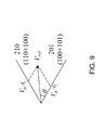
- each two adjacent voltage vectors e.g., 100 - 110 , 110 - 010 , 010 - 011 , 011 - 001 , 001 - 101 , 101 - 100
- inverter are combined to generate six new voltage vectors (e.g., 210 , 120 , 021 , 012 , 102 , 201 ).
- the output common-mode voltage will be kept to be zero.
- the reference voltage V* is combined by two adjacent new voltage vectors like normal space vector modulation (SVM).
- SVM is an algorithm for the control of PWM (i.e., SVPWM) used for the creation of alternating current (AC) waveforms; most commonly to drive three phase AC powered motors at varying speeds from DC source using multiple amplifiers. Then an active time for each new vector is distributed to the original voltage vectors in two inverters. In this way, the common-mode voltage of the paralleled inverter 505 can be eliminated and the common-mode EMI noise is significantly reduced. Also, because of the cancellation of the output voltage of the two inverters, the differential mode EMI noise and current ripple can also be reduced. Note that the new voltage vectors are with the length of 0.866 times of the original voltage vector, which modifies the modulation index from 1.15 to 1.
Landscapes
- Engineering & Computer Science (AREA)
- Power Engineering (AREA)
- Automation & Control Theory (AREA)
- Control Of Ac Motors In General (AREA)
- Inverter Devices (AREA)
Abstract
A system and/or method for controlling a dual-three-phase machine with respect to a power electronics inverter is provided. The dual-three-phase machine includes six phase windings divided into at least two windings groups configured to provide a combination of six voltages that achieve zero common-mode voltage and a significantly reduced common-mode noise current.
Description
This application is a Non-Provisional Application of U.S. Application No. 62/168,186, filed on May 29, 2015, the disclosure of which is incorporated by reference herein in its entirety.
The subject matter disclosed herein relates generally to the field of elevators, and more particularly to elevator power systems.
An elevator system, such as traction, hydraulic, and self-propelled elevator systems, based on the application (e.g., high rise buildings) can utilize a power system to propel a car within an elevator shaft. At present, the power system can employ a power electronics inverter (e.g., as variable speed alternating drive (AC) motor drive) to improve performance of the power system. However, switching of power electronics devices in power system includes inherent electromagnetic interference (EMI) problems.
In general, EMI noise can be divided into two major groups: differential mode (DM) noise and common-mode (CM) noise. DM noises are conducted between phases. CM noises are conducted together with all phases through the parasitic capacitors to the ground. CM noises are with serious concern for motor drives because CM noises increase the EMI in the motor drive and damage the motor bearing and winding insulation. Unfortunately, in certain applications, solutions such as adding CM filters to attenuate CM noises are not viable due to the significant weight penalty of each CM filter.
According to one embodiment, a power electronics system is provided. The power electronics system can comprise a power electronics converter configured as a motive drive and to provide pulse-width-modulation and a dual-three-phase machine comprising six phase windings divided into a first and second windings groups configured to result in a zero common-mode pulse width modulation across the at least two windings groups.
In the above embodiment, or in the alternative, each winding of the first windings groups can correspond to a winding of the second windings group.
In the above embodiments, or in the alternative, each winding of the first windings groups can be in-phase with a winding of the second windings group.
In the above embodiments, or in the alternative, the first and second windings groups can form a three-phase, 120° phase-shift machine.
In the above embodiments, or in the alternative, the power electronics system can further comprise a first neutral connection connecting the first windings group; and a second neutral connection connecting the second windings group, wherein the first neutral connection is separate from the second neutral connection.
In the above embodiments, or in the alternative, the first and second windings groups can be physically distributed in two segments of a stator of the power electronics system.
In the above embodiments, or in the alternative, the first and second windings groups can have an identical back-electro-magnetic-force for each winding pair.
In the above embodiments, or in the alternative, the power electronics system can further comprise a common-mode capacitor is between a common-neutral connection and a ground.
In the above embodiments, or in the alternative, the power electronics converter can be a paralleled inverter comprising a first inverter connected to the first windings group and a second inverter connected to the second windings group.
In the above embodiments, or in the alternative, the power electronics system can be included in a ropeless elevator system.
According to one embodiment, a method for controlling a dual-three-phase motor drive is provided. The method comprises generating, by a speed controller of the dual-three-phase motor, a reference current; generating, by a current controller of the dual-three-phase motor, a reference voltage based on the reference current; generating, by a zero-common mode pulse width modulation module of the dual-three-phase motor, two groups of pulse width modulated signals; providing the two groups of pulse width modulated signals to a paralleled inverter of the dual-three-phase motor; and driving, by the paralleled inverter, first and second windings groups of the dual-three-phase motor via the two groups of pulse width modulated signals.
In the above embodiment, or in the alternative, each winding of the first windings group can correspond to a winding of the second windings group.
In the above embodiments, or in the alternative, each winding of the first windings group can be in-phase with a winding of the second windings group.
In the above embodiments, or in the alternative, the first and second windings groups can form a three-phase, 120° phase-shift machine.
In the above embodiments, or in the alternative, the method can further comprise connecting each winding of the first windings group via a first neutral connection; and connecting each winding of the second windings group via a second neutral connection, wherein the first neutral connection is separate from the second neutral connection.
In the above embodiments, or in the alternative, the first and second windings groups can be physically distributed in two segments of a stator of the dual-three-phase motor.
In the above embodiments, or in the alternative, the first and second windings groups can have an identical back-electro-magnetic-force for each winding pair.
In the above embodiments, or in the alternative, the paralleled inverter can include a first inverter connected to the first windings group and a second inverter connected to the second windings group.
In the above embodiments, or in the alternative, the dual-three-phase motor can be included in a ropeless elevator system.
Additional features and advantages are realized through the techniques of the present disclosure. Other embodiments and aspects of the disclosure are described in detail herein. For a better understanding of the disclosure with the advantages and the features, refer to the description and to the drawings.
The foregoing and other features, and advantages are apparent from the following detailed description taken in conjunction with the accompanying drawings in which:
In general, embodiments herein relate to a dual-three-phase machine with respect to a power electronics inverter (e.g., a paralleled inverter) to minimize or eliminate common-code (CM) in a motor. Further, by coupling the dual-three-phase machine directly to the paralleled inverter any requirement for a coupling inductor is eliminated. This dual-three-phase machine can be employed in an elevator system (e.g., traction, hydraulic, and self-propelled elevator systems).
In one embodiment, the dual-three-phase machine is utilized in a power system of a ropeless elevator system, also referred to as self-propelled elevator system. For example, a linear motor system of the ropeless elevator system can employ a power electronics inverter (e.g., as variable speed alternating drive (AC) motor drive) to improve the performance of the linear motor system.
Above the top floor is an upper transfer station 30 to impart horizontal motion to elevator cars 14 to move elevator cars 14 between lanes 13, 15 and 17. It is understood that upper transfer station 30 may be located at the top floor, rather than above the top floor. Below the first floor is a lower transfer station 32 to impart horizontal motion to elevator cars 14 to move elevator cars 14 between lanes 13, 15 and 17. It is understood that lower transfer station 32 may be located at the first floor, rather than below the first floor. Although not shown in FIG. 1 , one or more intermediate transfer stations may be used between the first floor and the top floor. Intermediate transfer stations are similar to the upper transfer station 30 and lower transfer station 32.
In another embodiment, the dual-three-phase machine is utilized in an electric motor system of a traction elevator system. The traction elevator system also includes a hoistway having a plurality of lanes or shafts. In each shaft, an elevator car travels in one direction, i.e., up or down. The electric motor system utilizes the power electronics inverter (e.g., as variable speed alternating drive (AC) motor drive) to improve the performance of maneuvering the elevator cars via cables.
Turning to FIG. 2 , a three-phase paralleled inverter architecture 200 is shown with coupling inductors 201 to limit a circulation current. The architecture 200 includes two three- phase converters 202, 204, each of which includes three pairs of switches. The two three- phase converters 202, 204 are parallel by being connected to a same side of a direct current (DC) bus (e.g., Vdc/2 and −Vdc/2) and by terminals A1, B1, C1 and A2, B2, C2 being connected to the coupling inductor 201.
In the three-phase paralleled inverter architecture 200, an output CM voltage can be kept to be zero and EMI noise can be significantly reduced for the load by arranging the 12 pulse-width modulation (PWM) signals of switches of the two three- phase converters 202, 204. However, for this three phase machine, external coupling inductor 201 is required for inverter paralleling. The coupling inductors 201 can limit the circulating current between two inverters with its mutual inductance, but increase a system volume and a system weight, and make the system more complex.
Further, without paralleled inverters, three phase motor drives cannot be controlled with zero CM voltage due to an odd number of phases. With even number of phases, regular voltage source inverter (VSI) can be used as motor drive to achieve zero CM voltage theoretically. In this way, a dual-three-phase electrical machine can be driven by two three-phase inverters. Thus, embodiments are based on the dual-three-phase electrical machine with two three-phase inverters to achieve negligible CM noise. Compared with paralleled three-phase inverters for three-phase machine, no extra coupling inductor is needed for circulating current control. This part describes the novelty of this invention, by combining the coupling inductor's function in the existing motor winding and eliminate the coupling inductors in the previous UTAS patent
Further, the dual-three-phase machine 500 with the paralleled inverter 505 includes a common-neutral connection N3. The common-mode capacitor Cg is between the common-neutral connection N3 and the ground 510. Note that grounding/parasitic capacitor is a complex issue with respect to either a common neutral point for the two groups of three-phase windings or to separate neutral points for the two groups of three-phase windings. In both cases, the dual-three-phase machine 500 works to reduce the CM voltage and CM noise. In this way, the inverter terminal voltage can be modeled as pulse voltage to a DC mid-point by switching between the windings a1, b1, c1 and the windings a2, b2, c2. The common-mode voltage Vcm of the dual-three-phase machine 500 driven by the paralleled inverter 505 is shown in equation (1).
The common-mode voltage Vcm, will generate CM current through the parasitic capacitor Cg to
In view of the above, a concern for the dual-three-phase machine 500 driven by the paralleled inverter 505 is the circulating current in each pair of windings. That is, because the PWM voltages in each pair of windings are different, a circulating current is generated and the winding inductance is used to control it. To describe this concern, an equivalent circuit of FIG. 5 is shown, for example, in FIG. 6 in accordance with an embodiment.
Since the back-EMFs in each pair of windings are the same, they can be combined and diagram 605 can be modeled as a diagram 610. For example, because the winding a1 and the winding a2 have the same back-EMF Va and Va, because the winding b1 and the winding b2 have the same back-EMF Vb and Vb, and because the winding c1 and the winding c2 have the same back-EMF Vc and Vc, each pair of windings can be combined to have a three phase voltage Va, Vb, and Vc.
Thus, in the diagram 605, a series leakage inductance in each pair of windings (e.g., La1+La2, Lb1+Lb2, Lc1+Lc2) will work as circulating current limiter and paralleled inductance (e.g., La1//La2, Lb1//Lb2, Lc1//Lc2) will work as output inductance of the motor. Thus, with the architecture of dual-three-phase machine 500 as noted above, a mutual inductance is small and a main inductance of each pair of windings can work as circulating current limiter.
Turning now to FIG. 7 , a controller structure 700 of a dual-three-phase motor drive is illustrated. Reference current is generated by the speed controller 705 and sent to the current controller 410. The feedback current of the dual-three-phase motor are transferred to the d-q axis and compared with the reference current. The reference voltage is generated from current controller and sent to the zero-CM PWM module 715. PWM 1 and 2 signals for the two inverters 720, 725 are calculated in the zero-CM PWM module 715 and sent to drive the two groups of windings.
Turning now to FIGS. 8 and 9 , FIG. 8 illustrates a principal of the zero-CM PWM module 715 and FIG. 9 shows the voltage vector combination in an example sector (e.g., sector 1 of FIG. 8 ).
In FIG. 8 , each two adjacent voltage vectors (e.g., 100-110, 110-010, 010-011, 011-001, 001-101, 101-100) in inverter are combined to generate six new voltage vectors (e.g., 210, 120, 021, 012, 102, 201). With each new voltage vector, the output common-mode voltage will be kept to be zero. The reference voltage V* is combined by two adjacent new voltage vectors like normal space vector modulation (SVM). SVM is an algorithm for the control of PWM (i.e., SVPWM) used for the creation of alternating current (AC) waveforms; most commonly to drive three phase AC powered motors at varying speeds from DC source using multiple amplifiers. Then an active time for each new vector is distributed to the original voltage vectors in two inverters. In this way, the common-mode voltage of the paralleled inverter 505 can be eliminated and the common-mode EMI noise is significantly reduced. Also, because of the cancellation of the output voltage of the two inverters, the differential mode EMI noise and current ripple can also be reduced. Note that the new voltage vectors are with the length of 0.866 times of the original voltage vector, which modifies the modulation index from 1.15 to 1.
Table. 1 shows the active time arrangement for zero-CM PWM for dual-three-phase motor drive in sector 1. In the first half of t1 period, the new voltage vector is with 2,1,0 in FIG. 8 , inverter 1 is with 1,1,0 and inverter 2 is with 1,0,0. In the second half of t1 period, inverter 1 is with 1,0,0 and inverter 2 is with 1,1,0. Other voltage vectors can be arranged. This arrangement maintains the voltage balance of the two inverters in each switching cycle, as show.
| TABLE 1 |
| Active Time Arrangement For Zero-CM PWM For |
| Inverter |
| 1 | |
| t0/4 | 1, 1, 1 | 0, 0, 0 | ||
| t1/2 | 1, 1, 0 | 1, 0, 0 | ||
| t2/2 | 1, 0, 0 | 1, 0, 1 | ||
| t0/2 | 0, 0, 0 | 1, 1, 1 | ||
| t1/2 | 1, 0, 0 | 1, 1, 0 | ||
| t2/2 | 1, 0, 1 | 1, 0, 0 | ||
| t0/4 | 1, 1, 1 | 0, 0, 0 | ||
In view of the above, simulations were executed to produce results of the CM voltage between normal SVPWM and the zero-CM PWM in the dual-three-phase motor drive (e.g., machine 500), these results being utilize to validate the above embodiments. With normal SVPWM, the CM voltage is switching with the amplitude of Vdc/2. With the zero-CM PWM, CM voltage is negligible. Additionally, simulations were executed to compare a torque between with normal SVPWM and zero-CM PWM for dual-three-phase motor drive. These simulations showed that there was a reduction of less torque ripple with the zero-CM PWM.
In view of the above, the technical effects and benefits of embodiments of the six-phase electrical machines with negligible common-mode (e.g., a drive and motor system and/or method for a dual-three-phase machine with respect to a power electronics inverter) include eliminating of common-mode voltage for the dual-three-phase motor drive, significantly reducing a CM EMI noise and a CM current, and reducing a CM current damage to the motor insulation and bearing. Further, compared with paralleled inverters for a three-phase motor drive, the technical effects and benefits include the elimination of a coupling inductor. Furthermore, a winding self-inductance is used to control a circulating current, a power density can be significantly increased by the elimination of a CM filter and the coupling inductors, and a DM noise and torque ripple can be reduced for the motor. Moreover, a multi-segment based motor stator structure significantly reduces the cross-coupling between windings, while a fault-tolerant capability is also improved.
The terminology used herein is for the purpose of describing particular embodiments only and is not intended to be limiting. As used herein, the singular forms “a”, “an” and “the” are intended to include the plural forms as well, unless the context clearly indicates otherwise. It will be further understood that the terms “comprises” and/or “comprising,” when used in this specification, specify the presence of stated features, integers, steps, operations, elements, and/or components, but do not preclude the presence or addition of one more other features, integers, steps, operations, element components, and/or groups thereof.
The corresponding structures, materials, acts, and equivalents of all means or step plus function elements in the claims below are intended to include any structure, material, or act for performing the function in combination with other claimed elements as specifically claimed. The present disclosure has been presented for purposes of illustration and description, but is not intended to be exhaustive or limited to the form disclosed. Many modifications and variations will be apparent to those of ordinary skill in the art without departing from the scope and spirit of the disclosure. The embodiment was chosen and described in order to best explain the principles of embodiments and the practical application, and to enable others of ordinary skill in the art to understand the various embodiments with various modifications as are suited to the particular use contemplated.
Claims (10)
1. A power electronics system, comprising:
a power electronics converter configured as a motive drive and to provide pulse-width-modulation; and
a dual-three-phase machine comprising the power electronics converter, a current controller, six phase windings divided into a first and second windings groups, a common-neutral connection connecting the six phase windings, and a common-mode capacitor,
wherein the power electronics converter is a paralleled inverter comprising a first inverter connected to the first windings group and a second inverter connected to the second windings group,
wherein the paralleled inverter is configured to provide a pulse-width-modulation as a motor drive to the six phase windings to generate a zero common-mode pulse width modulation across the first and second windings groups; and
wherein the common-mode capacitor is between the common-neutral connection and a ground,
wherein the common-neutral connection comprises a first neutral connection connecting the first windings group and a second neutral connection, which is separate from the second neutral connection, connecting the second windings group,
wherein the zero common-mode pulse width modulation provided by the paralleled inverter utilizes a reference voltage generated by the current controller and comprises a triangle relationship defined by:
where t1 and t2 are two vectors corresponding to the first and second windings groups, Vref is the reference voltage with a position of angle θ, and Ts is a switching period,
wherein a voltage of the common-mode pulse width modulation is zero or negligible due to the triangle relationship,
wherein each winding of the first windings groups corresponds to and is in-phase with a winding of the second windings group.
2. The power electronics system of claim 1 , wherein the first and second windings groups form a three-phase, 120° phase-shift machine.
3. The power electronics system of claim 1 , wherein the first and second windings groups are physically distributed in two segments of a stator of the power electronics system.
4. The power electronics system of claim 1 , wherein the first and second windings groups have an identical back-electro-magnetic-force for each winding pair.
5. The power electronics system of claim 1 , wherein the power electronics system is included in an elevator system.
6. A method for controlling a dual-three-phase motor machine comprising a speed controller, a current controller, a zero-common mode pulse width modulation module, a paralleled inverter, six phase windings divided into a first and second windings groups, a common-neutral connection connecting the six phase windings, and a common-mode capacitor, the method comprising:
generating, by the speed controller of the dual-three-phase motor machine, a reference current;
generating, by the current controller of the dual-three-phase motor machine, a reference voltage based on the reference current;
generating, by the zero-common mode pulse width modulation module of the dual-three-phase motor machine, two groups of pulse width modulated signals;
providing the two groups of pulse width modulated signals to a paralleled inverter of the dual-three-phase motor; and
driving, by the paralleled inverter of the dual-three-phase motor machine, the paralleled inverter comprising a first inverter connected to the first windings group and a second inverter connected to the second windings group, first and second windings groups of the dual-three-phase motor via the two groups of pulse width modulated signals as a motor drive to the six phase windings to generate a zero common-mode pulse width modulation across the first and second windings groups,
wherein the common-mode capacitor is between the common-neutral connection and a ground,
wherein the common-neutral connection comprises a first neutral connection connecting the first windings group and a second neutral connection, which is separate from the second neutral connection, connecting the second windings group,
wherein the zero common-mode pulse width modulation provided by the paralleled inverter utilizes the reference voltage generated by the current controller and comprises a triangle relationship defined by:
where t1 and t2 are two vectors corresponding to the first and second windings groups, Vref is the reference voltage with a position of angle θ, and Ts is a switching period,
wherein a voltage of the common-mode pulse width modulation is zero or negligible due to the triangle relationship,
wherein each winding of the first windings groups corresponds to and is in-phase with a winding of the second windings group.
7. The method of claim 6 , wherein the first and second windings groups form a three-phase, 120° phase-shift machine.
8. The method of claim 6 , wherein the first and second windings groups are physically distributed in two segments of a stator of the dual-three-phase motor.
9. The method of claim 6 , wherein the first and second windings groups have an identical back-electro-magnetic-force for each winding pair.
10. The method of claim 6 , wherein the dual-three-phase motor is included in a ropeless elevator system.
Priority Applications (1)
| Application Number | Priority Date | Filing Date | Title |
|---|---|---|---|
| US15/131,543 US9985566B2 (en) | 2015-05-29 | 2016-04-18 | Dual three-phase electrical machine and drive with negligible common-mode noise |
Applications Claiming Priority (2)
| Application Number | Priority Date | Filing Date | Title |
|---|---|---|---|
| US201562168186P | 2015-05-29 | 2015-05-29 | |
| US15/131,543 US9985566B2 (en) | 2015-05-29 | 2016-04-18 | Dual three-phase electrical machine and drive with negligible common-mode noise |
Publications (2)
| Publication Number | Publication Date |
|---|---|
| US20160352278A1 US20160352278A1 (en) | 2016-12-01 |
| US9985566B2 true US9985566B2 (en) | 2018-05-29 |
Family
ID=56101294
Family Applications (1)
| Application Number | Title | Priority Date | Filing Date |
|---|---|---|---|
| US15/131,543 Active US9985566B2 (en) | 2015-05-29 | 2016-04-18 | Dual three-phase electrical machine and drive with negligible common-mode noise |
Country Status (3)
| Country | Link |
|---|---|
| US (1) | US9985566B2 (en) |
| EP (1) | EP3098963B1 (en) |
| CN (1) | CN106208856B (en) |
Cited By (7)
| Publication number | Priority date | Publication date | Assignee | Title |
|---|---|---|---|---|
| US20190181786A1 (en) * | 2017-12-07 | 2019-06-13 | General Electric Company | Systems and methods for rotating a crankshaft to start an engine |
| US10536096B2 (en) * | 2016-09-15 | 2020-01-14 | Siemens Aktiengesellschaft | Control of phase currents of an inverter |
| US10773922B2 (en) * | 2015-02-05 | 2020-09-15 | Otis Elevator Company | Drive and control for six-phase electrical machines with negligible common-mode voltage |
| US10985687B2 (en) | 2019-04-12 | 2021-04-20 | Hamilton Sundstrand Corporation | Common mode noise cancellation and DC ripple reduction techniques |
| US11095202B1 (en) | 2020-06-16 | 2021-08-17 | Ge Aviation Systems Llc | Method and apparatus for common-mode voltage cancellation |
| US11387761B2 (en) * | 2019-09-24 | 2022-07-12 | Rockwell Automation Technologies, Inc. | System and method for sinusoidal output and integrated EMC filtering in a motor drive |
| US20220247340A1 (en) * | 2019-07-25 | 2022-08-04 | Cummins Inc. | Fault tolerant operations of a six-phase machine |
Families Citing this family (24)
| Publication number | Priority date | Publication date | Assignee | Title |
|---|---|---|---|---|
| US9853570B2 (en) * | 2016-02-26 | 2017-12-26 | Deere & Company | Parallel inverter scheme for separating conduction and switching losses |
| EP3297150A1 (en) * | 2016-09-15 | 2018-03-21 | Siemens Aktiengesellschaft | Control of phase flows of inverter connected in parallel |
| US9871436B1 (en) * | 2016-11-15 | 2018-01-16 | Toshiba International Corporation | Three-phase three-level inverter with reduced common mode leakage current |
| CN106452218B (en) * | 2016-12-09 | 2019-01-29 | 华中科技大学 | A kind of modularization three-phase multiterminal motor and its drive control method |
| CN106936361A (en) * | 2017-04-18 | 2017-07-07 | 沈阳永磁电机制造有限公司 | A kind of pure square-wave motor control system of multi-phase permanent |
| CN107666261B (en) * | 2017-10-27 | 2019-12-10 | 沈阳工业大学 | SVPWM control method for double three-phase motor with low common-mode voltage |
| JP7054435B2 (en) * | 2017-11-16 | 2022-04-14 | 株式会社ジェイテクト | Motor control device |
| CN107919748B (en) * | 2017-11-21 | 2019-10-01 | 四川建筑职业技术学院 | A kind of high torque motor for multi-rotor unmanned aerial vehicle |
| CN108233755B (en) * | 2018-02-12 | 2020-01-31 | 武汉大学 | space vector pulse width modulation method for inhibiting common-mode voltage of multi-phase motor |
| KR102588932B1 (en) * | 2018-04-18 | 2023-10-16 | 현대자동차주식회사 | Inverter system for vehicle |
| CN108616214B (en) * | 2018-05-19 | 2020-05-15 | 哈尔滨工业大学 | Drive topology for eliminating PWM frequency noise of double three-phase motor |
| CN108540041B (en) * | 2018-05-19 | 2021-10-26 | 哈尔滨工业大学 | Circuit topology for eliminating PWM noise of double three-phase motor driven by H bridge |
| CN112438016B (en) * | 2018-09-07 | 2021-12-21 | 宇菱塑胶科技有限公司 | Motor driving device |
| JP7005471B2 (en) * | 2018-11-09 | 2022-01-21 | 株式会社Soken | Drive system |
| CN110380662B (en) * | 2019-07-20 | 2021-06-22 | 哈尔滨工业大学 | Topology for eliminating PWM noise of double-branch motor |
| CN112550079B (en) * | 2019-09-25 | 2022-09-06 | 比亚迪股份有限公司 | Energy conversion device and vehicle |
| EP4059129A4 (en) * | 2019-11-11 | 2023-07-19 | ABB E-Mobility B.V. | Multi-level power convertor and method for multi-level power convertor |
| FR3105641B1 (en) | 2019-12-19 | 2021-12-17 | Moving Magnet Tech | Three-phase double electric machine and method of controlling such a machine |
| DE102020201547A1 (en) * | 2020-02-07 | 2021-08-12 | Volkswagen Aktiengesellschaft | Stator of an electrical machine |
| CN112821737A (en) * | 2021-02-03 | 2021-05-18 | 华中科技大学 | Zero common mode voltage control circuit based on parallel inverter reduces circulating current |
| CN112953351B (en) * | 2021-02-18 | 2023-04-18 | 中国第一汽车股份有限公司 | Inverter system |
| CN113255281B (en) * | 2021-05-19 | 2024-04-09 | 江苏大学 | Fault-tolerant type low short-circuit current double-three-phase permanent magnet motor winding design method |
| KR20230013947A (en) * | 2021-07-20 | 2023-01-27 | 현대자동차주식회사 | Motor driving apparatus and method |
| CN113844296A (en) * | 2021-09-19 | 2021-12-28 | 浙江大学 | Electric automobile integrated charger based on double three-phase motors and control method thereof |
Citations (21)
| Publication number | Priority date | Publication date | Assignee | Title |
|---|---|---|---|---|
| US4441064A (en) | 1981-12-18 | 1984-04-03 | General Electric Company | Twelve-pulse operation of a controlled current inverter motor drive |
| US5648894A (en) | 1994-09-30 | 1997-07-15 | General Electric Company | Active filter control |
| US5852558A (en) | 1997-06-20 | 1998-12-22 | Wisconsin Alumni Research Foundation | Method and apparatus for reducing common mode voltage in multi-phase power converters |
| US6040989A (en) | 1999-05-06 | 2000-03-21 | Emerson Electric Co | Device and method for generating three-phase sine waves using two pulse-width modulators |
| EP1052769A2 (en) | 1999-05-14 | 2000-11-15 | Nissan Motor Co., Ltd. | Inverter and motor |
| US6337803B2 (en) | 1999-06-24 | 2002-01-08 | Nissan Motor Co., Ltd. | Power module |
| US6392905B1 (en) | 2001-01-06 | 2002-05-21 | Ford Global Technologies, Inc. | Method and circuit for reducing battery ripple current in a multiple inverter system of an electrical machine |
| US6486632B2 (en) | 2000-09-04 | 2002-11-26 | Nissan Motor Co., Ltd. | Control device for motor/generators |
| US7046527B2 (en) | 2003-05-09 | 2006-05-16 | Distributed Power, Inc. | Power converter with ripple current cancellation using skewed switching techniques |
| US20060192520A1 (en) * | 2005-02-28 | 2006-08-31 | Rockwell Automation Technologies, Inc. | Cancellation of dead time effects for reducing common mode voltages |
| US7342330B2 (en) | 2004-10-05 | 2008-03-11 | Japan Servo Co., Ltd. | Hybrid type double three-phase electric rotating machine |
| US7372712B2 (en) | 2005-09-23 | 2008-05-13 | Gm Global Technology Operations, Inc. | Multiple inverter system with single controller and related operating method |
| DE102007040166A1 (en) | 2007-08-21 | 2009-06-10 | Oriental Motor Co., Ltd. | Motor control device for application of motor with multiple independent phase coils, has multiple operating units of inverter type for operation of appropriate phase coils, and has multiple pulse width modulated control unit |
| US20100071970A1 (en) * | 2008-09-23 | 2010-03-25 | Gm Global Technology Operations, Inc. | Electrical system using phase-shifted carrier signals and related operating methods |
| US7868573B2 (en) | 2006-01-14 | 2011-01-11 | Converteam Uk Ltd | Drive circuits |
| US7956563B2 (en) * | 2007-07-30 | 2011-06-07 | GM Global Technology Operations LLC | System for using a multi-phase motor with a double-ended inverter system |
| US7990098B2 (en) * | 2007-07-30 | 2011-08-02 | GM Global Technology Operations LLC | Series-coupled two-motor drive using double-ended inverter system |
| WO2014182272A1 (en) | 2013-05-06 | 2014-11-13 | Otis Elevator Company | Linear motor stator core for self-propelled elevator |
| US8928264B2 (en) | 2012-04-05 | 2015-01-06 | Denso Corporation | Control device for rotating electrical machine |
| US20150349626A1 (en) * | 2014-05-30 | 2015-12-03 | Hamilton Sundstrand Corporation | Output filter for paralleled inverter |
| US20160329705A1 (en) * | 2013-12-18 | 2016-11-10 | Thales | Modular and reconfigurable electrical power conversion device |
Family Cites Families (2)
| Publication number | Priority date | Publication date | Assignee | Title |
|---|---|---|---|---|
| CN201197132Y (en) * | 2008-02-04 | 2009-02-18 | 深圳市陆地方舟电动车有限公司 | Vector control AC variable-frequency control system of electric car |
| US10773922B2 (en) * | 2015-02-05 | 2020-09-15 | Otis Elevator Company | Drive and control for six-phase electrical machines with negligible common-mode voltage |
-
2016
- 2016-04-18 US US15/131,543 patent/US9985566B2/en active Active
- 2016-05-25 EP EP16171358.1A patent/EP3098963B1/en active Active
- 2016-05-26 CN CN201610356468.3A patent/CN106208856B/en active Active
Patent Citations (23)
| Publication number | Priority date | Publication date | Assignee | Title |
|---|---|---|---|---|
| US4441064A (en) | 1981-12-18 | 1984-04-03 | General Electric Company | Twelve-pulse operation of a controlled current inverter motor drive |
| US5648894A (en) | 1994-09-30 | 1997-07-15 | General Electric Company | Active filter control |
| US5852558A (en) | 1997-06-20 | 1998-12-22 | Wisconsin Alumni Research Foundation | Method and apparatus for reducing common mode voltage in multi-phase power converters |
| US6040989A (en) | 1999-05-06 | 2000-03-21 | Emerson Electric Co | Device and method for generating three-phase sine waves using two pulse-width modulators |
| EP1052769A2 (en) | 1999-05-14 | 2000-11-15 | Nissan Motor Co., Ltd. | Inverter and motor |
| US6236583B1 (en) * | 1999-05-14 | 2001-05-22 | Nissan Motor Co., Ltd. | Inverter and motor |
| US6337803B2 (en) | 1999-06-24 | 2002-01-08 | Nissan Motor Co., Ltd. | Power module |
| US6486632B2 (en) | 2000-09-04 | 2002-11-26 | Nissan Motor Co., Ltd. | Control device for motor/generators |
| US6392905B1 (en) | 2001-01-06 | 2002-05-21 | Ford Global Technologies, Inc. | Method and circuit for reducing battery ripple current in a multiple inverter system of an electrical machine |
| US7046527B2 (en) | 2003-05-09 | 2006-05-16 | Distributed Power, Inc. | Power converter with ripple current cancellation using skewed switching techniques |
| US7342330B2 (en) | 2004-10-05 | 2008-03-11 | Japan Servo Co., Ltd. | Hybrid type double three-phase electric rotating machine |
| US20060192520A1 (en) * | 2005-02-28 | 2006-08-31 | Rockwell Automation Technologies, Inc. | Cancellation of dead time effects for reducing common mode voltages |
| US7372712B2 (en) | 2005-09-23 | 2008-05-13 | Gm Global Technology Operations, Inc. | Multiple inverter system with single controller and related operating method |
| US7868573B2 (en) | 2006-01-14 | 2011-01-11 | Converteam Uk Ltd | Drive circuits |
| US7956563B2 (en) * | 2007-07-30 | 2011-06-07 | GM Global Technology Operations LLC | System for using a multi-phase motor with a double-ended inverter system |
| US7990098B2 (en) * | 2007-07-30 | 2011-08-02 | GM Global Technology Operations LLC | Series-coupled two-motor drive using double-ended inverter system |
| DE102007040166A1 (en) | 2007-08-21 | 2009-06-10 | Oriental Motor Co., Ltd. | Motor control device for application of motor with multiple independent phase coils, has multiple operating units of inverter type for operation of appropriate phase coils, and has multiple pulse width modulated control unit |
| US20100071970A1 (en) * | 2008-09-23 | 2010-03-25 | Gm Global Technology Operations, Inc. | Electrical system using phase-shifted carrier signals and related operating methods |
| US8928264B2 (en) | 2012-04-05 | 2015-01-06 | Denso Corporation | Control device for rotating electrical machine |
| WO2014182272A1 (en) | 2013-05-06 | 2014-11-13 | Otis Elevator Company | Linear motor stator core for self-propelled elevator |
| US20160083226A1 (en) * | 2013-05-06 | 2016-03-24 | Otis Elevator Company | Linear motor stator core for self-propelled elevator |
| US20160329705A1 (en) * | 2013-12-18 | 2016-11-10 | Thales | Modular and reconfigurable electrical power conversion device |
| US20150349626A1 (en) * | 2014-05-30 | 2015-12-03 | Hamilton Sundstrand Corporation | Output filter for paralleled inverter |
Non-Patent Citations (10)
| Title |
|---|
| DI ZHANG ; FEI WANG ; R. BURGOS ; D. BOROYEVICH: "Common-Mode Circulating Current Control of Paralleled Interleaved Three-Phase Two-Level Voltage-Source Converters With Discontinuous Space-Vector Modulation", IEEE TRANSACTIONS ON POWER ELECTRONICS, INSTITUTE OF ELECTRICAL AND ELECTRONICS ENGINEERS, USA, vol. 26, no. 12, 1 December 2011 (2011-12-01), USA, pages 3925 - 3935, XP011479936, ISSN: 0885-8993, DOI: 10.1109/TPEL.2011.2131681 * |
| Di Zhang et al: "Common-Mode Circulating Current Control of Paralleled Interleaved Three-Phase Two-Level Voltage-Source Converters With Discontinuous Space-Vector Modulation", IEEE Transactions on Power Electronics, Institute of Electrical and Electronics Engineers, USA, vol. 26, No. ,12, Dec. 1, 2011 (Dec. 1, 2011), pp. 3925-3935, XP011479936. * |
| Di Zhang, et al., "Common-Mode Circulating Current Control of Paralleled Interleaved Three-Phase Two-Level Voltage-Source Converters With Discontinuous Space-Vector Modulation", IEEE Transactions on Power Electronics, vol. 26, No. 12, Dec. 2011, pp. 3925-3935. |
| EPSR for EP Application No. 16171358.1, dated Nov. 22, 2016, 11 pages. |
| G. Oriti, et al., "An Inverter/Motor Drive With Common Mode Voltage Elimination", IEEE Industry Application Society Annual Meeting, New Orleans, Louisiana, Oct. 5-9, 1997, pp. 587-592. |
| Oriti G et al: "An inverter/motor drive with common mode voltage elimination", Industry Applications Conference, 1997. Thirty-Second IAS Annual Meeting, IAS '97., Conference Record of the 1997 IEEE New Orleans, LA, USA Oct. 5-9, 1997, New York, NY, USA,IEEE, US, vol. 1, Oct. 5, 1997 (Oct. 5, 1997), pp. 587-592, XP010248630. * |
| ORITI G., JULIAN L., LIPO T.A.: "An inverter/motor drive with common mode voltage elimination", INDUSTRY APPLICATIONS CONFERENCE, 1997. THIRTY-SECOND IAS ANNUAL MEETI NG, IAS '97., CONFERENCE RECORD OF THE 1997 IEEE NEW ORLEANS, LA, USA 5-9 OCT. 1997, NEW YORK, NY, USA,IEEE, US, vol. 1, 5 October 1997 (1997-10-05) - 9 October 1997 (1997-10-09), US, pages 587 - 592, XP010248630, ISBN: 978-0-7803-4067-1, DOI: 10.1109/IAS.1997.643127 * |
| Zhihong Ye et al: "Paralleling non-isolated multi-phase PWM converters", Industry Applications Conference, 2000. Conference Record of the 2000 IEEE Oct. 8-12, 2000, Iscataway, NJ, USA,IEEE, vol. 4, Oct. 8, 2000 (Oct. 8, 2000), pp. 2433-2439, XP010522596, ISBN: 978-0-7803-6401-1. * |
| ZHIHONG YE, BOROYEVICH D., LEE F.C.: "Paralleling non-isolated multi-phase PWM converters", INDUSTRY APPLICATIONS CONFERENCE, 2000. CONFERENCE RECORD OF THE 2000 IEEE 8-12 OCTOBER 2000, PISCATAWAY, NJ, USA,IEEE, vol. 4, 8 October 2000 (2000-10-08) - 12 October 2000 (2000-10-12), pages 2433 - 2439, XP010522596, ISBN: 978-0-7803-6401-1 * |
| Zhihong Ye, et al., "Paralleling Non-Isolated Multi-Phase PWM Converters", Center for Power Electronics Systems, Virginia Polytechnic Institute and State University, Blacksburg, VA, IEEE, 2000, pp. 2433-2439. |
Cited By (9)
| Publication number | Priority date | Publication date | Assignee | Title |
|---|---|---|---|---|
| US10773922B2 (en) * | 2015-02-05 | 2020-09-15 | Otis Elevator Company | Drive and control for six-phase electrical machines with negligible common-mode voltage |
| US10536096B2 (en) * | 2016-09-15 | 2020-01-14 | Siemens Aktiengesellschaft | Control of phase currents of an inverter |
| US20190181786A1 (en) * | 2017-12-07 | 2019-06-13 | General Electric Company | Systems and methods for rotating a crankshaft to start an engine |
| US10608565B2 (en) * | 2017-12-07 | 2020-03-31 | General Electric Company | Systems and methods for rotating a crankshaft to start an engine |
| US10985687B2 (en) | 2019-04-12 | 2021-04-20 | Hamilton Sundstrand Corporation | Common mode noise cancellation and DC ripple reduction techniques |
| US20220247340A1 (en) * | 2019-07-25 | 2022-08-04 | Cummins Inc. | Fault tolerant operations of a six-phase machine |
| US11777437B2 (en) * | 2019-07-25 | 2023-10-03 | Cummins Inc. | Fault tolerant operations of a six-phase machine |
| US11387761B2 (en) * | 2019-09-24 | 2022-07-12 | Rockwell Automation Technologies, Inc. | System and method for sinusoidal output and integrated EMC filtering in a motor drive |
| US11095202B1 (en) | 2020-06-16 | 2021-08-17 | Ge Aviation Systems Llc | Method and apparatus for common-mode voltage cancellation |
Also Published As
| Publication number | Publication date |
|---|---|
| US20160352278A1 (en) | 2016-12-01 |
| CN106208856A (en) | 2016-12-07 |
| EP3098963B1 (en) | 2021-09-01 |
| CN106208856B (en) | 2021-03-30 |
| EP3098963A3 (en) | 2016-12-21 |
| EP3098963A2 (en) | 2016-11-30 |
Similar Documents
| Publication | Publication Date | Title |
|---|---|---|
| US9985566B2 (en) | Dual three-phase electrical machine and drive with negligible common-mode noise | |
| US10773922B2 (en) | Drive and control for six-phase electrical machines with negligible common-mode voltage | |
| CN108377118B (en) | Parallel interleaved bi-level or tri-level regenerative drive | |
| JP5815696B2 (en) | Open delta motor drive using integrated charging | |
| EP3706309B1 (en) | Rotary electric machine control device | |
| CN101043197B (en) | Drive circuit | |
| EP3104517A2 (en) | Paralleled active front-end rectifiers with negligible common-mode | |
| EP2950434A1 (en) | Output filter with interphase reactor for paralleled inverters | |
| EP2950440B1 (en) | Pulse-width modulation control of paralleled inverters | |
| CN110383639B (en) | Rotating electric machine system | |
| Pramanick et al. | A harmonic suppression scheme for full speed range of a two-level inverter fed induction motor drive using switched capacitive filter | |
| JP7218460B2 (en) | 3-phase motor drive | |
| EP3800782B1 (en) | Rotating electrical machine control device | |
| US20180002142A1 (en) | Six-phase motor for elevator system | |
| Sharma et al. | Direct torque control of symmetrical six-phase induction machine using nine switch inverter | |
| JP6469332B1 (en) | Electric motor drive | |
| Ye et al. | Torque ripple and copper loss minimization for a family of mutually coupled switched reluctance machines | |
| EP4084324A1 (en) | Rotary electric machine control device | |
| Arashloo et al. | Ripple free fault tolerant control of five phase permanent magnet machines | |
| JP2011130525A (en) | Electric motor drive system | |
| JP7391130B2 (en) | Inverter drive method | |
| EP4170896A1 (en) | Rotary electric machine control device | |
| CN116982249A (en) | Linear motor with long stator | |
| JPH08337365A (en) | Control device of linear motor elevator |
Legal Events
| Date | Code | Title | Description |
|---|---|---|---|
| AS | Assignment |
Owner name: OTIS ELEVATOR COMPANY, CONNECTICUT Free format text: ASSIGNMENT OF ASSIGNORS INTEREST;ASSIGNOR:JIANG, DONG;REEL/FRAME:038307/0456 Effective date: 20150624 |
|
| STCF | Information on status: patent grant |
Free format text: PATENTED CASE |
|
| MAFP | Maintenance fee payment |
Free format text: PAYMENT OF MAINTENANCE FEE, 4TH YEAR, LARGE ENTITY (ORIGINAL EVENT CODE: M1551); ENTITY STATUS OF PATENT OWNER: LARGE ENTITY Year of fee payment: 4 |