US9820530B2 - Knit article of footwear with customized midsole and customized cleat arrangement - Google Patents
Knit article of footwear with customized midsole and customized cleat arrangement Download PDFInfo
- Publication number
- US9820530B2 US9820530B2 US14/598,447 US201514598447A US9820530B2 US 9820530 B2 US9820530 B2 US 9820530B2 US 201514598447 A US201514598447 A US 201514598447A US 9820530 B2 US9820530 B2 US 9820530B2
- Authority
- US
- United States
- Prior art keywords
- cleat
- midsole
- customized
- designed
- arrangement
- Prior art date
- Legal status (The legal status is an assumption and is not a legal conclusion. Google has not performed a legal analysis and makes no representation as to the accuracy of the status listed.)
- Active, expires
Links
Images


Classifications
-
- A—HUMAN NECESSITIES
- A43—FOOTWEAR
- A43B—CHARACTERISTIC FEATURES OF FOOTWEAR; PARTS OF FOOTWEAR
- A43B13/00—Soles; Sole-and-heel integral units
- A43B13/02—Soles; Sole-and-heel integral units characterised by the material
- A43B13/12—Soles with several layers of different materials
- A43B13/122—Soles with several layers of different materials characterised by the outsole or external layer
-
- A—HUMAN NECESSITIES
- A43—FOOTWEAR
- A43B—CHARACTERISTIC FEATURES OF FOOTWEAR; PARTS OF FOOTWEAR
- A43B1/00—Footwear characterised by the material
- A43B1/0027—Footwear characterised by the material made at least partially from a material having special colours
-
- A—HUMAN NECESSITIES
- A43—FOOTWEAR
- A43B—CHARACTERISTIC FEATURES OF FOOTWEAR; PARTS OF FOOTWEAR
- A43B1/00—Footwear characterised by the material
- A43B1/02—Footwear characterised by the material made of fibres or fabrics made therefrom
- A43B1/04—Footwear characterised by the material made of fibres or fabrics made therefrom braided, knotted, knitted or crocheted
-
- A—HUMAN NECESSITIES
- A43—FOOTWEAR
- A43B—CHARACTERISTIC FEATURES OF FOOTWEAR; PARTS OF FOOTWEAR
- A43B13/00—Soles; Sole-and-heel integral units
- A43B13/02—Soles; Sole-and-heel integral units characterised by the material
- A43B13/12—Soles with several layers of different materials
-
- A—HUMAN NECESSITIES
- A43—FOOTWEAR
- A43B—CHARACTERISTIC FEATURES OF FOOTWEAR; PARTS OF FOOTWEAR
- A43B13/00—Soles; Sole-and-heel integral units
- A43B13/14—Soles; Sole-and-heel integral units characterised by the constructive form
- A43B13/22—Soles made slip-preventing or wear-resisting, e.g. by impregnation or spreading a wear-resisting layer
- A43B13/223—Profiled soles
-
- A—HUMAN NECESSITIES
- A43—FOOTWEAR
- A43B—CHARACTERISTIC FEATURES OF FOOTWEAR; PARTS OF FOOTWEAR
- A43B23/00—Uppers; Boot legs; Stiffeners; Other single parts of footwear
- A43B23/02—Uppers; Boot legs
- A43B23/04—Uppers made of one piece; Uppers with inserted gussets
- A43B23/042—Uppers made of one piece
-
- G—PHYSICS
- G06—COMPUTING; CALCULATING OR COUNTING
- G06Q—INFORMATION AND COMMUNICATION TECHNOLOGY [ICT] SPECIALLY ADAPTED FOR ADMINISTRATIVE, COMMERCIAL, FINANCIAL, MANAGERIAL OR SUPERVISORY PURPOSES; SYSTEMS OR METHODS SPECIALLY ADAPTED FOR ADMINISTRATIVE, COMMERCIAL, FINANCIAL, MANAGERIAL OR SUPERVISORY PURPOSES, NOT OTHERWISE PROVIDED FOR
- G06Q30/00—Commerce
- G06Q30/06—Buying, selling or leasing transactions
- G06Q30/0601—Electronic shopping [e-shopping]
- G06Q30/0621—Item configuration or customization
-
- G—PHYSICS
- G06—COMPUTING; CALCULATING OR COUNTING
- G06Q—INFORMATION AND COMMUNICATION TECHNOLOGY [ICT] SPECIALLY ADAPTED FOR ADMINISTRATIVE, COMMERCIAL, FINANCIAL, MANAGERIAL OR SUPERVISORY PURPOSES; SYSTEMS OR METHODS SPECIALLY ADAPTED FOR ADMINISTRATIVE, COMMERCIAL, FINANCIAL, MANAGERIAL OR SUPERVISORY PURPOSES, NOT OTHERWISE PROVIDED FOR
- G06Q30/00—Commerce
- G06Q30/06—Buying, selling or leasing transactions
- G06Q30/0601—Electronic shopping [e-shopping]
- G06Q30/0633—Lists, e.g. purchase orders, compilation or processing
-
- G—PHYSICS
- G06—COMPUTING; CALCULATING OR COUNTING
- G06Q—INFORMATION AND COMMUNICATION TECHNOLOGY [ICT] SPECIALLY ADAPTED FOR ADMINISTRATIVE, COMMERCIAL, FINANCIAL, MANAGERIAL OR SUPERVISORY PURPOSES; SYSTEMS OR METHODS SPECIALLY ADAPTED FOR ADMINISTRATIVE, COMMERCIAL, FINANCIAL, MANAGERIAL OR SUPERVISORY PURPOSES, NOT OTHERWISE PROVIDED FOR
- G06Q30/00—Commerce
- G06Q30/06—Buying, selling or leasing transactions
- G06Q30/0601—Electronic shopping [e-shopping]
- G06Q30/0641—Shopping interfaces
- G06Q30/0643—Graphical representation of items or shoppers
-
- A—HUMAN NECESSITIES
- A43—FOOTWEAR
- A43D—MACHINES, TOOLS, EQUIPMENT OR METHODS FOR MANUFACTURING OR REPAIRING FOOTWEAR
- A43D2200/00—Machines or methods characterised by special features
- A43D2200/60—Computer aided manufacture of footwear, e.g. CAD or CAM
Definitions
- the present invention relates generally to a method of manufacturing footwear, and in particular to a method for manufacturing an article of footwear having a knit outsole with customized cleat placement and with a customized midsole.
- Workman teaches a boot with a replaceable sole plate
- Workman fails to teach a system and/or method where a customer can design a customized cleat configuration. Instead, Workman only teaches a system where a customer can swap one preconfigured clear design along the bottom of a sole plate with another preconfigured design.
- Tsuji U.S. Pat. No. 6,598,324 teaches a bowling shoe having customizable ground engagement.
- Tsuji discloses a bowling shoe construction that has various options for removing and replacing slide parts to attach to the tread surface of a slide shoe.
- Tsuji teaches the use of annular cleats with a slide shoe.
- Tsuji discloses various arrangements of the annular cleats that may be used with the slide pad, the holes corresponding to the annular cleats are preconfigured, and are not customizable by the user or customer.
- Tsuji teaches the use of annular cleats for bowling shoes that are intended to be used on smooth wooden surfaces, not the use of cleats intended to penetrate into both natural and synthetic turf.
- aspects of the disclosure relate to a method for producing a customized midsole and a customized cleat arrangement for an article of footwear comprising a knit outsole.
- the method includes obtaining information relating to a customized cleat arrangement in a knit outsole and other information relating to a midsole customized to the user's foot and having cleat reinforcements arranged to match the cleat arrangement on the knit outsole.
- the information is used to form an article of footwear including the customized knit outsole and the customized midsole.
- aspects of the disclosure provide a method for producing a customized midsole and a customized cleat arrangement for an article of footwear comprising a knit outsole.
- the method includes providing a cleat graphical interface system, a set of cleat graphics tools associated with the cleat graphical interface system, and a group of pre-designed cleat arrangements.
- Each pre-designed cleat arrangement in the group of pre-designed cleat arrangements includes a knit outsole representation having pre-defined cleat locations and a pre-defined number of cleats.
- the method also includes providing a midsole graphical interface system, a set of midsole graphics tools associated with the midsole graphical interface system, and a group of pre-designed midsoles.
- Each pre-designed midsole in the group of pre-designed midsoles includes reinforcement members projecting from the bottom of the midsole.
- Information related to a customized cleat arrangement including at least a knit outsole representation associated with a selected one pre-designed cleat arrangement from the group of pre-designed cleat arrangements that has been modified to change at least one of the pre-defined cleat locations and the pre-defined number of cleats is received from the cleat graphical interface system.
- information related to a customized midsole including at least one representation of the impression of the user's foot or of the reinforcement members associated with a selected one pre-designed midsole arrangement from the group of pre-designed midsole arrangements that has been modified to change at least one of the pre-defined reinforcement locations and the representation of the impression of the user's foot is received from the midsole graphical interface system.
- An article of footwear with the customized midsole and the customized cleat arrangement including the at least one knit outsole representation having at least one changed pre-defined cleat location and changed pre-defined number of cleats and including a customized midsole including at least one changed pre-defined location or changed pre-defined number of cleats and a modified midsole representation having at least one changed representation of the impression of the user's foot or reinforcing member is produced.
- the disclosure provides a method for customizing an article of footwear comprising a sole system including a knit outsole and a midsole.
- the knit outsole has a ground-engaging side that includes a location for a ground-engaging cleat member and a top side.
- the midsole has a top side customized to the user's foot and a bottom side having a rigid protrusion, the location and size of which is customized to the user.
- the method includes permanently installing the bottom side of the midsole in contact with the top side of the outsole, with the rigid protrusion on the bottom of the midsole in registration with the location for the ground-engaging cleat member, and pressing the bottom side of the midsole into the knit outsole to stretch the knit outsole in the location for the ground-engaging cleat member to permanently install the midsole and to form the ground-engaging cleat member.
- the disclosure provides another method for customizing an article of footwear comprising a sole system including a knit outsole and a midsole.
- the knit outsole has a top side and a ground-engaging side that has a knit member extending away from the ground-engaging side.
- the midsole has a top side customized to the user's foot and a bottom side having a rigid protrusion, the location and size of which is customized to the user and located in registration with the knit member on the ground-engaging side.
- the method includes permanently installing the bottom side of the midsole in contact with the top side of the outsole with the rigid protrusion on the bottom of the midsole in registration with the ground-engaging cleat member.
- the bottom side of the midsole is pressed into the knit outsole to permanently install the midsole and to form the ground-engaging cleat member.
- the disclosure provides a method for customizing an article of footwear comprising a one-piece knitted component that encloses the foot and includes a sole system including a knit outsole and a midsole.
- the knit outsole had a ground-engaging side including a location for a ground-engaging cleat member and a top side.
- the top side of the midsole is customized to the user and the bottom side has a rigid protrusion.
- the location and size of the rigid protrusion is customized to the user's foot.
- the bottom side of the midsole is in contact with the top side of the outsole with the rigid protrusion on the bottom of the midsole in registration with the location for the ground-engaging cleat member.
- the bottom side of the midsole is pressed into the knit outsole to stretch the knit outsole in the location for the ground-engaging cleat member to permanently install the midsole and to form the ground-engaging cleat member.
- the disclosure provides a method for ordering a customized midsole and a customized cleat arrangement for an article of footwear comprising a knit outsole.
- a user interacts with a cleat graphical interface system and selects a first pre-designed cleat arrangement from a group of pre-designed cleat arrangements that include a representation of a knit outsole having pre-defined cleat locations and a pre-defined number of cleats.
- the user selects a cleat graphics tool and interacts with the cleat graphical interface system by modifying the representation of the knit outsole displayed within the cleat graphical interface system to alter at least one of the pre-defined cleat locations or the pre-defined number of cleats to create a customized cleat arrangement.
- the customized cleat arrangement including at least one changed pre-defined cleat location or changed pre-defined number of cleats within the cleat graphical interface system.
- a first pre-designed midsole is selected from a group of pre-designed midsoles that include pre-defined locations for cleat reinforcing members in registration with cleats in the customized cleat arrangement by interacting with a midsole graphical interface system.
- the representation of the midsole displayed within the midsole graphical interface system is modified using the selected midsole graphics tool to alter the first-designed midsole such that at least one of the representation of the impression of the user's foot or the reinforcing members is changed to create a customized midsole arrangement.
- the customized midsole arrangement including at least one changed representation of the impression of the user's foot or reinforcing member within the midsole graphical interface system is displayed.
- a finalized design including a modified knit outsole representation having the customized cleat arrangement including at least one changed pre-defined location or changed pre-defined number of cleats and a modified midsole representation having at least one changed representation of the impression of the user's foot or reinforcing member, is submitted to order the shoe.
- the invention provides a method for ordering a customized cleat arrangement for an article of footwear having a knit outsole, comprising the steps of: interacting with a graphical interface system; modifying an knit outsole representation; selecting a graphics tool from a set of graphics tools; using the graphics tool to create a customized cleat arrangement; and submitting a finalized design including an knit outsole representation with a customized cleat arrangement, and ordering the article of footwear having a knit outsole.
- FIG. 1 is an embodiment of a midsole and cleat customization system
- FIG. 2 is an embodiment of a process for a midsole and cleat customization system
- FIG. 3 is an embodiment of a detailed process for a midsole and cleat customization system
- FIG. 4 is an embodiment of a graphical interface system displaying multiple sized knit outsoles
- FIG. 5 is an embodiment of a graphical interface system displaying a knit outsole representation
- FIG. 6 is an embodiment of a graphical interface system displaying a knit outsole representation
- FIG. 7 is an embodiment of a graphical interface system displaying a knit outsole representation
- FIG. 8 is an embodiment of a graphical interface system displaying a customized color design on a knit outsole and customized cleat arrangement
- FIG. 9 is an embodiment of steps for customizing a midsole
- FIG. 10 is an embodiment of a method for customizing a midsole
- FIG. 11 is an embodiment of a step of 3-D printing of a customized midsole
- FIG. 12 is an embodiment of a knitting machine for knitting a knit
- FIG. 13 is an embodiment of knitting a knit textile element
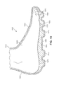
- FIG. 14 is a perspective view of an embodiment of a knit outsole portion with a custom cleat location
- FIG. 15 is a representation of the relationship between a customized midsole and a customized knit outsole
- FIG. 16 is a bottom view of an exemplary embodiment of an article of footwear having a knit outsole having a customized cleat arrangement before a foot-enclosing portion is formed;
- FIG. 17 is a perspective view of the bottom of an exemplary embodiment of the article of footwear having a knit outsole of FIG. 16 as the foot-enclosing portion is formed;
- FIG. 18 is perspective view of an exemplary embodiment of the completed article of footwear having a knit outsole of FIG. 16 and FIG. 17 ;
- FIG. 19 is a cross-sectional view of a user's foot in an article of footwear having a knit outsole
- FIG. 20 is an embodiment of a pair of footwear having a knit outsole being prepared and shipped to a pre-designated address.
- FIG. 1 is a schematic diagram of an illustrative embodiment of midsole and cleat customization system 101 .
- the term customization system refers to a system for manufacturing articles of footwear having a knit outsole through the production of easily customizable portions of an article of footwear having a knit outsole. In some embodiments, these portions may be customized by the manufacturer or a third party designer. In an embodiment, the portions may be customized by the party purchasing the articles of footwear having a knit outsole.
- midsole and cleat customization system 101 may be used to manufacture customized cleat arrangements for any type of footwear having a knit outsole. Examples include, but are not limited to, football shoes, soccer shoes, baseball shoes, hiking boots, as well as other types of footwear having a knit outsole. Generally, any type of footwear having a knit outsole including cleats may be manufactured using midsole and cleat customization system 101 .
- midsole and cleat customization system 101 comprises a remote terminal 100 connected to factory 102 by way of network 104 .
- remote terminal 100 may be any type of computer, including either a desktop or a laptop computer.
- remote terminal 100 may be any type of device that includes a display, a processor, and the ability to transmit and receive data from a remote network. Examples of such devices include, but are not limited to, PDA's, cell phones, as well as other types of devices.
- factory 102 represents a manufacturing system configured to manufacture articles of footwear having a knit outsole.
- factory 102 is shown as a single building for illustrative purposes only. In many cases, factory 102 will comprise many buildings. In some cases, factory 102 may comprise many buildings that are disposed in different geographic locations.
- the term factory may also refer to distributors and/or suppliers. In other words, the term factory may also apply to various operations on the manufacturing side, including the operations responsible for parts, labor, and/or retail of the article of footwear having a knit outsole, as well as other manufacturing side operations.
- Network 104 may be configured to relay information between computer 100 and factory 102 .
- network 104 may be a system allowing for the exchange of information between remote terminal 100 and factory 102 .
- Examples of such networks include, but are not limited to, personal area networks, local area networks, wide area networks, client-server networks, peer-to-peer networks, as well as other types of networks.
- the network may support wired transmissions, wireless transmissions, or both wired and wireless transmissions.
- network 104 may be a packet-switched communications system.
- network 104 may be the Internet.
- information may be transferred between the customer and the manufacturer using other provisions.
- information may be exchanged via mail, fax, courier, as well as other forms of communication.
- Midsole and cleat customization system 101 may include provisions that allow a customer to design a portion of an article of footwear having a knit outsole that will be produced by a manufacturer.
- midsole and cleat customization system 101 includes provisions that allow a customer to design a customized cleat arrangement for an article of footwear having a knit outsole.
- a customer may use midsole and cleat customization system 101 to select the arrangement of cleats, as well as the size and type of cleats used with an article of footwear having a knit outsole.
- a customer may use midsole and cleat customization system 101 to customize a midsole used in an article of footwear having a knit outsole.
- FIG. 2 is an embodiment of a method for designing a customized midsole and a customized cleat arrangement using midsole and cleat customization system 101 .
- a customer may interact with a website in order to design a customized cleat arrangement. In some cases, the customer may select a pre-designed customized cleat arrangement.
- information relating to the user's foot is obtained. Foot information may be obtained by any suitable method, including but not limited to physical measurements or impressions on deformable surfaces, computer-related scanning, or 3-D imaging.
- the foot information is used, together with the custom knit cleat arrangement of step 202 , to generate a custom midsole assembly in step 206 .
- the custom midsole assembly includes a top side having a custom foot-contacting surface and a bottom side having a rigid protrusion matching or registering with a cleat as arranged in step 202 .
- the manufacturer may receive the customer's design, as in fourth step 208 .
- the article of footwear having a knit outsole, including the customized cleat arrangement may be manufactured (knitted) according to the customer's design during fifth step 210 .
- the midsole assembly is manufactured in step 212 .
- the customized midsole has a projection from the bottom side to register with and reinforce a cleat in the knit outsole.
- the midsole is inserted into the article of footwear and urged into place as part of step 214 , wherein the rigid protrusion is inserted into or registered with a corresponding cleat member.
- the article of footwear having a knit outsole, including a customized cleat arrangement may be shipped to a pre-designated address that may belong to the customer, a retail store or another party.
- midsole and cleat customization system 101 may be best understood by separating the steps associated with remote terminal 100 and foot information system 103 on the one hand and those associated with factory 102 on the other hand.
- those steps associated with remote terminal 100 are performed on or by remote terminal 100
- those steps associated with foot information are performed in foot information step 103
- those steps associated with factory 102 are performed on or by factory 102 .
- a customer may access a remote website with remote terminal 100 .
- the customer may use the website to design an article of footwear having a knit outsole with a customized cleat arrangement during this step.
- the term website is used in the most general sense as meaning any collection of data located on a remote server accessible with a web browser of some kind.
- a website may be a collection of web pages found on the World Wide Web.
- the term web page may refer to any HTML/XHTML document.
- factory 102 includes a server of some type that supports a website with a graphical interface system.
- This graphical interface system may be used to design an article of footwear having a knit outsole with a customized cleat arrangement.
- the graphical interface system may be a graphical editor of some kind.
- the graphical interface system may provide a set of tools that allow the customer to easily design a customized cleat arrangement for an article of footwear.
- a website supporting a graphical interface system may be hosted outside of factory 102 .
- the website may be owned and run by a third party separate from the manufacturer of the customizable articles of footwear having a knit outsole.
- the process of customizing an article of footwear having a knit outsole may proceed as before.
- the finalized design information will be processed and sent to the manufacturer by the third party.
- the finalized design may be submitted to factory 102 during second step 304 .
- the submission may be transferred through the Internet.
- the submission may occur by way of mail, fax, or other forms of communication.
- foot information system 103 Information about the user's foot is obtained from foot information system 103 .
- a customer may make foot information available in a number of ways in step 301 .
- the user's foot may be physically measured.
- foot information may be obtained in digital form, such as by a computer scan.
- foot information may be obtained by any 3-D imaging. Such systems are described in more detail below, particularly in relationship with FIG. 9 .
- a customer may access a remote website with remote terminal 100 .
- the customer may use the website to design an article of footwear having a knit outsole with a customized cleat arrangement during this step.
- the term website is used in the most general sense as meaning any collection of data located on a remote server accessible with a web browser of some kind.
- a website may be a collection of web pages found on the World Wide Web.
- the term web page may refer to any HTML/XHTML document.
- factory 102 includes a server of some type that supports a website with a graphical interface system.
- This graphical interface system may be used to design an article of footwear having a knit outsole with a customized cleat arrangement.
- the graphical interface system may be a graphical editor of some kind.
- the graphical interface system may provide a set of tools that allow the customer to easily design a customized cleat arrangement for an article of footwear.
- a website supporting a graphical interface system may be hosted outside of factory 102 .
- the website may be owned and run by a third party separate from the manufacturer of the customizable articles of footwear having a knit outsole.
- the process of customizing an article of footwear having a knit outsole may proceed as before.
- the finalized design information will be processed and sent to the manufacturer by the third party.
- the finalized design may be submitted to factory 102 during second step 304 .
- the submission may be transferred through the Internet.
- the submission may occur by way of mail, fax or other forms of communication.
- factory 102 may receive and review the customized design during third step 306 .
- midsole assembly options include the compositions of matter comprising the footbed, and comprising the protrusion, for example.
- the location of any protrusions will be related to the location of any cleats in the customized cleat arrangement selected in step 302 .
- factory 102 includes a server of some type that supports a foot information system.
- This foot information system may be used to design an article of footwear having a customized cleat arrangement.
- a server supporting a foot information system may be hosted outside of factory 102 .
- the website may be owned and run by a third party separate from the manufacturer of the customizable articles of footwear having a knit outsole.
- the process of customizing an article of footwear having a customized midsole may proceed as before. In this case, the finalized design information will be processed and sent to the manufacturer by the third party.
- the finalized midsole assembly may be submitted to factory 102 during step 305 .
- the submission may be transferred through the Internet.
- the submission may occur by way of mail, fax, or other forms of communication.
- factory 102 may receive and review the entire customized design during step 306 .
- both the customized knit cleat arrangement and the midsole assembly configuration may be reviewed for errors, such as a mismatch between cleat locations and protrusion locations from the bottom of the midsole, for example.
- a midsole layout may be prepared based on the customized design information for both top surface and the bottom surface layers of the midsole received from the customer.
- the midsole may be manufactured.
- a textile element may be knitted in accordance with the customized cleat arrangement designed by the user.
- the textile element may be stiffened.
- portions of the textile elements are stiffened.
- the entirety of the textile element may be set, for example, by exposure to steam.
- the portions of the textile element may be knit from fusible yarns that, when heated, may fuse to form a hard surface.
- a ground-engaging portion such as the outsole or the bottom of the article of footwear may be such a surface, to reduce damage.
- the midsole assembly may be associated with the knit textile, as illustrated by step 316 .
- the midsole assembly may be associated with the knit textile by inserting the midsole into the textile element, typically by way of the opening for the ankle or by wrapping the article of footwear is wrapped around the foot to enclose it. Then, the midsole may be pushed down into registration with the outsole. The projections on the midsole then may be inserted into the cleats on the knit portion to form the assembly.
- the finished article of footwear having a knit outsole may be inspected during step 320 .
- the article of footwear having a knit outsole may be shipped from factory 102 to a pre-designated shipping address.
- a customer has access to a remote terminal. Using the remote terminal, the customer may gain access to a website supplied by the manufacturer or a third party.
- the website may include a graphical interface system, as discussed briefly in first step 302 .
- each step in the process of using a midsole and cleat customization system may be performed at a single location, or at different locations.
- a midsole and cleat customization system could be associated with a retail store.
- a clerk or employee of the retail store may help the customer to determine a customized cleat arrangement.
- the clerk may help the customer select a customized cleat arrangement using a website.
- the clerk may use other provisions for helping the customer to select a customized cleat arrangement.
- one or more employees of the retail store can perform the steps of making the article with a customized cleat arrangement using one or more machines that may be located at the retail location.
- the steps of making the article with customized cleat placement may be performed at a location different than a retail store or a factory. For example, these steps may be performed at an intermediate facility, like a distributor, or at a different facility, like a customization facility.
- Embodiments of the disclosure contemplate obtaining user's foot information from the user, for example, by scanning the foot, or from a database, as illustrated in FIG. 9 .
- steps of customization may occur in different places, such as in a retail store, or in a computer database.
- a customer can leave the store with a pair of footwear having a knit outsole including a customized cleat arrangement without having to wait for the footwear to ship.
- a retail store may be provided with a knitting machine to knit the customized textile and a 3-D printer for manufacturing the customized midsole.
- graphical interface system 400 may be used to design a customized cleat arrangement.
- a user may be initially prompted to select a size for an article of footwear having a knit outsole.
- four footwear sizes are shown, including first footwear size 401 , second footwear size 402 , third footwear size 403 , and fourth footwear size 404 .
- Each of these footwear sizes 401 - 404 may be associated with a particular shoe size.
- first footwear size could be a size 7
- second footwear size 402 could be a size 8
- third footwear size 403 could be a size 9
- fourth footwear size 404 could be a size 10 , each of these sizes referring to men's sizes. Only four footwear sizes are shown here for the purposes of illustration; however in other embodiments any number of sizes of footwear having a knit outsole could be shown.
- graphical interface system 400 may not include visual diagrams for each footwear size, but may instead include a drop-down list for selecting the desired footwear size. In some cases, a customer may be allowed to select a first size for the left foot and a second (possibly different) size for the right foot.
- graphical interface system 400 may include pointer 406 , used for making selections using graphical interface system 400 .
- pointer 406 used for making selections using graphical interface system 400 .
- a user could select second footwear size 402 , as shown in FIG. 4 .
- graphical interface system 400 may display knit outsole representation 502 .
- the knit outsole of the current footwear design is the bottom most layer of the midsole/outsole structure of the article of footwear having a knit outsole that will receive cleats. The details associated with this knit outsole will be discussed later in this detailed description.
- the term knit outsole representation 502 refers to a two-dimensional embodiment of a knit outsole within graphical interface system 400 . Specifically, the term knit outsole representation in the discussion of these embodiments includes the structural design of the represented knit outsole. Additionally, the term knit outsole representation in the discussion of these embodiments also includes any other design attributes including, but not limited to, patterns, shapes, designs, colors, images, and any other graphical feature of the outer surface of the represented knit outsole.
- knit outsole representation 502 is depicted here in the form of a plain knit outsole. However, in other embodiments, such as those represented in FIG. 8 , knit outsole representation 502 may include various graphical designs and colors. In some embodiments, knit outsole representation 502 may have a different shape, including various additional structural features.
- graphical interface system 400 includes provisions for designing a customized cleat arrangement.
- a user may manually select the location of one or more cleats on knit outsole representation 502 using pointer 406 once pointer tool 407 has been selected, as shown in FIG. 5 .
- first cleat 531 is disposed at lateral side 510 of knit outsole representation 502 .
- Graphical interface system 400 may also include grid lines 504 that may be turned on and off using grid line tool 506 .
- grid lines 504 may allow for a user to accurately arrange the positions for each cleat on knit outsole representation.
- the density of grid lines 504 may be modified. Additionally, in some embodiments only horizontal grid lines may be used, and in other embodiments only vertical grid lines may be used.
- FIG. 6 is an embodiment of knit outsole representation 502 including first cleat 531 and second cleat 532 .
- second cleat 532 has been positioned at forward portion 540 of knit outsole representation 502 .
- second cleat 532 may be positioned using pointer 406 .
- grid lines 504 may be used to determine the preferred spacing between first cleat 531 and second cleat 532 .
- FIG. 7 is an embodiment of a finished customized cleat arrangement associated with knit outsole representation 502 .
- first cleat 531 , second cleat 532 , third cleat 533 , fourth cleat 534 , and fifth cleat 535 may be disposed on forefoot portion 542 of knit outsole representation 502 .
- sixth cleat 536 and seventh cleat 541 are disposed on midfoot portion 543
- eighth cleat 537 , ninth cleat 538 , tenth cleat 539 , and eleventh cleat 540 are disposed on heel portion 544 of knit outsole representation 502 .
- graphics toolbar 520 includes a set of cleat sizes 522 , including small cleat size 524 , medium cleat size 526 , and large cleat size 528 . This arrangement allows a user to choose the size and location of each cleat.
- cleats 531 - 534 and cleats 537 - 540 may be associated with medium cleat size 526 .
- Cleat 535 , cleat 536 , and cleat 541 may be associated with large cleat size 528 . This configuration may allow a user's heel to penetrate firmly into the ground during circumstances where their feet are flat on the ground, but limit the degree of penetration of the forefoot into the ground during motions such as running, where only a portion of the heel is contacting the ground.
- knit outsole representation 502 is shown within graphical interface system 400 as a top down view, in other embodiments, the orientation or view of knit outsole representation 502 may be changed. In some embodiments, this may include a provision for moving knit outsole representation 502 to various regions of graphical interface system 400 . In other embodiments, this may include a provision for rotating knit outsole representation 502 about a set of axes. Modifying the view of knit outsole representation 502 may better facilitate the user in designing a customized cleat arrangement.
- a customized cleat arrangement can be determined by measuring one or more characteristics of a foot of a customer. For example, in one embodiment, a clerk at a retail store may use pressure mapping technology to determine customized pressure information about the foot of the customer. The clerk may then record that information and use the information to generate a customized cleat arrangement for the customer.
- graphical interface system 400 may include a group of pre-designed customized cleat arrangements associated with various sports and/or positions. In some embodiments, a user could select one of these pre-designed arrangements and, in some cases, make modifications to them using the previously discussed tools associated with graphical interface system 400 .
- FIG. 8 is an embodiment of graphical interface 700 for customizing yarn colors for knit outsole representation 702 .
- FIG. 8 illustrates a different color for each of the forefoot portion, the midfoot portion, and the heel portion, and a longitudinal stripe essentially down the middle of the article of footwear.
- Tool bar 710 displays colors available, including white yarn 711 , green yarn 712 , black yarn 713 , and blue yarn 714 . Other colors also may be available.
- Knit outsole representation 702 illustrates a longitudinal black stripe 709 essentially dividing the knit outsole representation into lateral and medial halves, white forefoot medial portion 703 and white lateral forefoot portion 706 , green midfoot medial portion 704 and green midfoot lateral portion 707 , and blue heel portion lateral portion 705 and blue heel portion medial portion 708 . These and other colors may be included in a customized knit outsole. Both the color selection and the cleat arrangement contribute to the customization of the article of footwear. In other embodiments, other characteristics associated with different yarns may be available, such as types, textures, denier, or other qualities of yarns used to form the various portions of the knit outsole.
- different pre-designed customized cleat arrangements can be associated with different types of medical conditions.
- a customer with sensitive pressure regions on a particular part of the foot can select a pre-designated customized cleat arrangement that is configured to help avoid applying pressure directly to those pressure regions.
- a user can search for various types of medical conditions using a drop down menu as described above. Examples of medical conditions associated with the foot include, but are not limited to, sesamoiditis, heel spurs, heel fissures, arch pain, as well as other medical conditions associated with the foot.
- the customization system may then generate a pre-designated customized cleat arrangement according to the selected medical condition.
- a pre-designated customized cleat arrangement may be generated that has few or no cleats disposed near the ball of the foot.
- a user may choose to use this pre-designated customized cleat arrangement or the customer may choose to modify the arrangement using the graphical interface system.
- different pre-designed customized midsoles may be associated with different types of medical conditions. For example, a customer with a particular region of the sole of the foot sensitive to pressure, such as a bunion, may seek an arrangement configured to avoid application of pressure to this area. In another embodiment, a customer with heel pain may select a specific configuration in the heel portion.
- a pair of footwear having a knit outsole may be designed using midsole and cleat customization system 101 . Any designs, tools, or other mechanisms applied to the design of one article of footwear having a knit outsole may likewise be applied to a second, complementary, article of footwear having a knit outsole.
- the term complementary refers to the association of a left knit outsole associated with a left article of footwear having a knit outsole with a right knit outsole associated with a right article of footwear having a knit outsole and vice-versa.
- a distinct customized cleat arrangement could be applied to a first knit outsole and a second knit outsole.
- the complementary knit outsoles need not include identical cleat arrangements or arrangements that are mirror images of each other. This configuration may be useful for a kicker in football who desires a greater number of cleats on the foot that is planted during a kick in order to provide a greater amount of traction, but shorter cleats on the kicking foot.
- a first midsole and a second midsole need not be identical or mirror images of each other.
- a customer may design a customized midsole and cleat arrangement without the use of graphical interface system 400 .
- a customer could use a form supplied by the manufacturer to design a customized midsole and cleat arrangement associated with an article of footwear having a knit outsole. This form could then be mailed, faxed or otherwise sent to the manufacturer at factory 102 .
- a kit, a deformable device, or a deformable pad that would record relevant characteristics of the user's foot also could be included.
- the customer could travel to a retailer and use a form or other provision provided by the retailer to design a customized cleat arrangement. The retailer could then communicate this customized design using mail, fax, or the Internet, to the manufacturer at factory 102 .
- FIG. 9 is a schematic diagram illustrating different sources of foot information and how that information is processed to result in information useful for manufacturing a customized midsole.
- Foot information system 900 operates on foot information obtained from at least two sources.
- One source of foot information illustrated is database 902 , in which the user or others already have stored information. For example, a manufacturer from which the used had bought articles of footwear previously may have put the user's foot information into database 902 . Alternatively, a third party may have obtained and saved foot information for the user as a matter of convenience for the user.
- foot information Another source of foot information is foot information that is scanned. Scanned foot information may be obtained, for example, at the point of sale, by a digital computer scan or by 3-D imagery. Alternatively, a physical impression of the foot, such as on a paper or in a retentive medium, may be obtained. These and other method of obtaining foot information may be used to provide foot information 904 .
- User foot information thus obtained 906 may be used in some embodiments in an optional midsole assembly customization step 908 .
- This optional customization assembly step may be helpful when a user seeks to customize the midsole.
- the midsole footbed, the top surface or upper surface of the midsole may be customized to comport with the bottom of the user's foot to provide comfort and support to the foot.
- the midsole top surface also may be customized to accommodate a physical anomaly or provide extra cushioning.
- the arrangement of the protrusions also may be customized to accommodate such anomalies while still placing the projections in registration with the customized cleat arrangement.
- FIG. 10 schematically illustrates the steps of manufacturing a midsole having a customized top surface and a customized bottom surface with a projection.
- Process 1000 includes step 1002 of obtaining the final customized knit cleat arrangement from a remote terminal at which the arrangement was designed, from a manufacturer to which the arrangement was transmitted, or from any source.
- Customized knit cleat arrangement 1002 is used in step 1004 to prepare a bottom surface of a midsole.
- the bottom surface may be formed in any suitable manner, including but not limited to molding, carving or shaping (material removal from a larger piece), 3-D printing, or any suitable way.
- the midsole bottom surface may be formed from rigid materials, such as rigid plastic or metal, or from deformable materials, such as deformable polymers or deformable polymer foams. Rigid materials may be useful in providing reinforcement to the customized cleat arrangement.
- the bottom surface is formed by 3-D printing of material that forms a rigid shape.
- Midsole assembly configuration 1006 is used to prepare the top surface layout at step 1008 .
- the top surface may be the foot-enclosing portion of the midsole.
- the top surface layout prepared at step 1008 then is used to manufacture a top surface on a midsole at step 1010 .
- the top surface may be rigid or flexible. In some embodiments, the top surface is rigid, with minimal flexibility, to provide support and rigidity to the knit outsole surface.
- a customized top surface is formed to the shape of the bottom of the user's foot.
- a rigid surface not only provides support to the knit outsole surface, but also provides support to the user's foot.
- An insole (not shown), such as a foot-shaped cushioning pad, may be used to provide comfort and cushioning, especially with a rigid midsole.
- the midsole that results from manufacturing assembly 1010 may be unitary or may be assembled for multiple pieces of material.
- the top surface of the midsole and the bottom surface, including the projections, of a midsole may be formed from different compositions of matter.
- a midsole is formed by 3-D printing.
- FIG. 11 illustrates a method of forming midsole 1102 in 3-D printer 1100 .
- Midsole 1102 is in place on knit outsole 1104 on shelf or table 1106 .
- the composition of matter forming the midsole may be any material that is amenable of 3-D printing.
- 3-D print head 1108 may deliver material 1110 through nozzle 1112 .
- a computer (not shown) may control the deposition of material 1110 by controlling the delivery rate of material through nozzle 1112 and the location of nozzle 1110 . The process is repeated at different areas of the midsole, with material 1110 accreting to the midsole until the design is completely formed.
- FIG. 12 and FIG. 13 illustrate an exemplary process of knitting a knitted component 1400 , which may include elements such as a knit outsole. Although knitting may be performed by hand, the commercial manufacture of knitted components is generally performed by knitting machines. An example of a knitting machine 1200 that is suitable for producing any of the knitted components described herein is depicted in FIG. 12 . Knitting machine 1200 has a configuration of a V-bed flat knitting machine for purposes of example, but any of the knitted components described herein may be produced on other knitting machines.
- Knitting machine 1200 includes first needle bed 1232 and second needle bed 1234 having needles 1202 that are angled with respect to each other, thereby forming a V-bed. That is, needles 1202 from first needle bed 1232 lay on a first plane, and needles 1202 from the second needle bed 1234 lay on a second plane. The first plane and the second plane are angled relative to each other and meet to form an intersection that extends along a majority of a width of knitting machine 1200 . As described in greater detail below, needles 1202 each have a first position where they are retracted and a second position where they are extended. In the first position, needles 1202 are spaced from the intersection where the first plane and the second plane meet. In the second position, however, needles 1202 pass through the intersection where the first plane and the second plane meet.
- Rail 1203 and rail 1205 extend above and parallel to the intersection of needles 1202 and provide attachment points for standard feeder 1204 .
- Rail 1203 and rail 1205 each have two sides, each of which may accommodate one standard feeder. Therefore, knitting machine 1200 may include a total of four feeders. Three such feeders are illustrated in FIG. 10 .
- Standard feeder 1204 is on the front of rail 1203
- feeder 1214 is on the front of rail 1205
- feeder 1224 is on the back of rail 1205 .
- additional rails could be present. Such additional rails would accommodate additional feeders.
- Such feeders may be useful to manufacture embodiments including two or more types of yarn. These additional feeders are supplied with yarn and are operated in the same way as the feeders described in detail.
- Feeder 1204 moves along rail 1203 and needle beds 1232 and 1234 , thereby supplying yarn to needles 1202 .
- Yarn 1206 is provided to feeder 1204 by a spool 1207 . More particularly, yarn 1206 extends from spool 1207 to various yarn guides 1208 , yarn take-back spring 1209 , and yarn tensioner 1210 before entering feeder 1204 .
- additional spools 1207 may be utilized to provide yarns to other feeders.
- Standard feeders are conventionally utilized for a V-bed flat knitting machine 1200 .
- Each feeder has the ability to supply yarn that needles 1202 manipulate to knit, tuck, and float.
- only one feeder may be needed.
- more than one feeder may be utilized.
- a knitting machine 1200 in FIG. 12 may include first standard feeder 1204 , second standard feeder 1214 , and third standard feeder 1224 that are substantially similar to each other.
- First standard feeder 1204 may be secured to a front side of rail 1203
- second standard feeder 1214 may be secured to a front side of rail 1205
- third standard feeder 1224 may be secured to a rear side of rail 1205 .
- additional feeders may be used and may be located on the front or rear side of rail 1203 .
- first yarn 1206 from spool 1207 passes through first standard feeder 1204 and an end of yarn 1206 extends outwardly from first dispensing tip 1213 at the end of first feeder arm 1212 .
- any other strand e.g., a filament, thread, rope, webbing, cable, chain, or yarn
- a second yarn similarly passes through second standard feeder 1214 and extends outwardly from second dispensing tip 1233 on second feeder arm 1215 .
- a third yarn (not shown) may pass in a similar manner through third standard feeder 1224 to third dispensing tip 1233 on third feeder arm 1227 .
- Needles 1202 are manipulated to form loops 1206 , with a plurality of loops forming knitted component 1260 .
- the knitting process discussed herein relates to the formation of a knitted component 1260 , which may be any knitted component, including a component that includes a textile element such as a knit outsole.
- a knitted component 1260 may be any knitted component, including a component that includes a textile element such as a knit outsole.
- a relatively small section of knitted component 1260 is shown in the Figures in order to permit the knit structure to be illustrated.
- the scale or proportions of the various elements of knitting machine 1200 and knitted component 1260 may be enhanced to better illustrate the knitting process.
- First standard feeder 1204 includes first feeder arm 1212 with first dispensing tip 1213 .
- First feeder arm 1212 is angled to position first dispensing tip 1213 in a location that is (a) centered between needles 1202 and (b) above an intersection of needle beds 1201 .
- needles 1202 lay on different planes, which planes are angled relative to each other. That is, needles 1202 lay on the different planes of first needle bed 1232 and second needle bed 1234 .
- Needles 1202 each have a first position in which needles 1202 are retracted, and a second position, in which needles 1202 are extended. In the first position, needles 1202 are spaced from the intersection where the planes upon which needle beds 1201 meet.
- first dispensing tip 1213 , second dispensing tip 1223 , and third dispensing tip 1233 are located above the intersection of the planes. In this position, first dispensing tip 1213 , second dispensing tip 1223 , and third dispensing tip 1233 supply yarn to needles 1202 for purposes of knitting, tucking, and floating.
- first standard feeder 1204 moves along rail 1203 and a new course is formed in knitted component 1260 from yarn 1206 . More particularly, needles 1202 pull sections of yarn 1206 through the loops of the prior course, thereby forming the new course. Accordingly, courses may be added to knitted component 1260 by moving standard feeder 1204 along needles 1202 , thereby permitting needles 1202 to manipulate yarn 1206 and form additional loops from yarn 1206 .
- Knitted components described herein can be formed from at least one yarn that is manipulated (e.g., with a knitting machine) to form a plurality of intermeshed loops that define a knitted component having a variety of courses and wales.
- adjacent areas of a knitted component can share at least one common course or at least one common wale.
- knitted components can have the structure of a knitted textile. It will be appreciated that the knitted components can be formed via weft knitting operations, including flat knitting operations and circular knitting operations, warp knitting operations, or other suitable methods.
- the knitted components may Incorporate various types and combinations of stitches and yarns.
- the yarn forming the knitted components may have one type of stitch in one area of a knitted component and another type of stitch in another area of the knitted component.
- areas of knitted components may have a plain knit structure, a mesh knit structure, or a rib knit structure, for example.
- the different types of stitches may affect the physical properties of a knitted component, including aesthetics, stretch, thickness, air permeability, and abrasion-resistance. That is, the different types of stitches may impart different properties to different areas of the knitted component.
- the knitted component may have one type of yarn in one area and another type of yarn in a different area of the knitted component.
- FIG. 14 illustrates a portion of knitted component 1400 .
- the portion illustrated is that portion in which the customized cleat arrangement 1410 has been formed.
- Knitted component 1400 which may include a textile element, such as embodiments of the knit outsole, is knit in accordance with an appropriate method.
- Ground-engaging cleat members may be formed.
- the textile may be steamed to set the yarn, in accordance with known processes.
- areas of the textile element may be stiffened. Typically, such stiffening would be useful in areas of the textile element subject to heavy abrasion.
- Fusible yarn may be used in this area, for example, on portions of knitted components corresponding to protuberances forming ground-engaging cleat members.
- Fusible yarn may be heated to soften the outer surfaces of the yarn.
- a stiffening resin or plastic may be applied and activated and cured or heated. Then, the final folding, matching, sticking and adhering to form the article of footwear is carried out to form an article of footwear.
- Knitted components including knit outsole elements, may be formed of unitary knit construction.
- unitary knit construction means that the respective component is formed as a one-piece element through a knitting process. That is, the knitting process substantially forms the various features and structures of unitary knit construction without the need for significant additional manufacturing steps or processes.
- a unitary knit construction may be used to form a knitted component having structures or elements that include one or more courses of yarn or other knit material that are joined such that the structures or elements include at least one course in common (i.e., sharing a common yarn) and/or include courses that are substantially continuous between each of the structures or elements. With this arrangement, a one-piece element of unitary knit construction is provided.
- a knitted component remains formed of unitary knit construction when other elements, such as logos, trademarks, placards with care instructions or other information, such as material information and size, tensile or structural elements, are added following the knitting procedure.
- FIG. 15 illustrates the relationship between customized knit outsole 1500 and customized midsole 1550 .
- Customized knit outsole 1500 includes customized cleat arrangement 1510 .
- Customized midsole 1550 includes a customized arrangement of protrusions 1560 in registration with the customized cleat arrangement, as illustrated.
- Customized midsole 1550 also includes customized areas 1570 of top surface 1580 .
- FIG. 16 illustrates knitted component 1630 that includes customized knit outsole 1611 and foot-enclosing knit portion 1640 formed of a unitary knit construction
- FIG. 16 illustrates an essentially planar or flat foot-enclosing knit portion 1640 comprising sole system 1610 and knitted component 1630
- Knitted component 1630 is illustrated in two elements on opposite sides of sole system 1610 .
- Sole system 1610 includes knitted component 1611 , one-piece knit outsole 1612 having bottom surface 1614 , and ground-engaging cleat member 1615 having bottom 1616 .
- Line of demarcation 1617 is illustrated for purposes of reference. The line of demarcation is not a physical object, but rather is an aid to visualizing the regions of the knitted component.
- the protrusions of a customized midsole have been inserted into the cleats of the customized knit outsole 1612 .
- the perimeter of the customized midsole essentially coincides with line of demarcation 1617 .
- FIG. 16 , FIG. 17 , and FIG. 18 illustrate an exemplary process of forming article of footwear 1660 from foot-enclosing knit portion 1640 , which is flat or planar in FIG. 16 , and is configured into a completed article of footwear 1660 in FIG. 18
- FIG. 17 illustrates an intermediate stage, wherein foot-enclosing knit portion 1640 has been folded or bent upward from about line of demarcation 1617 , clearly distinguishing sole system 1610 from knitted component 1630 .
- Knitted component 1611 , one-piece knit outsole 1612 having bottom surface 1614 , and ground-engaging cleat member 1615 having bottom 1616 are clearly visible as part of sole system 1610 .
- the forefoot area is completely formed, but the elements of knitted component 1630 have not been brought together.
- FIG. 18 illustrates a complete article of footwear 1660 from foot-enclosing knit portion 1640 .
- Article of footwear 1660 comprising knitted component 1630 and sole system 1610 .
- Upper 1620 is formed by stitching or otherwise attaching the ends of knitted component 1630 at seam 1627 in the forefoot region and the midfoot region and at seam 1629 in the heel region to form a void for a user's foot.
- seam 1627 and seam 1629 resulting from the stitching or joining together of the sides of knitted component 1630 may be located essentially on the longitudinal midline of article of footwear 1660 if the size of knitted component 1630 is essentially the same on each side of article of footwear 1660 , as illustrated in the drawing Figures herein. In other embodiments of the disclosure, the seam may be located anywhere on the surface of upper 1620 . Such an adjustment can be made by making one side of knitted component 1630 wider than the other.
- Line of demarcation 1617 illustrates a dividing line between sole system 1610 and other components of the article of footwear 1660 .
- Ground-engaging cleat member 1615 protrudes away from the bottom side or surface 1614 of one-piece knit outsole 1612 .
- FIG. 19 is an illustration in cross-section of a foot 1999 inside a finished shoe 1900 in accordance with embodiments of the invention.
- Customized midsole 1950 including customized top surface 1970 and projections 1960 arranged in registration with the cleats in customized cleat arrangement 1910
- Knit element 1940 extends around and encloses the foot.
- Knit element includes knit outsole 1900 and knit foot-enclosing portion 1980 .
- the article of footwear produced may be delivered to the user.
- the article of footwear will be put into a container and delivered to the user.
- a matched pair of articles of footwear is prepared, as illustrated in FIG. 20 .
- Once assembled footwear 2010 may be associated with complementary assembled footwear 2020 and shipped in container 2030 to a pre-designated address as supplied by the customer.
- complementary assembled footwear 2010 has been customized according to a process similar to the process described here for customizing the cleat arrangement of assembled footwear 2010 .
Abstract
Method for producing a customized midsole and a customized cleat representation for an article of footwear comprising a knit outsole. The method includes obtaining information relating to a customized cleat arrangement in a knit outsole and other information relating to a midsole customized to the user's foot and having cleat reinforcements arranged to match the cleat arrangement on the knit outsole. The information is used to form an article of footwear including the customized knit outsole and the customized midsole.
Description
The present invention relates generally to a method of manufacturing footwear, and in particular to a method for manufacturing an article of footwear having a knit outsole with customized cleat placement and with a customized midsole.
Designs discussing interchangeable cleats, including adjustable cleat patterns, have been previously discussed. Workman (U.S. Pat. No. 6,813,847) teaches a boot with a replaceable sole plate. The boot has a cavity located in the bottom of the sole and a sole plate that releasably fits within this cavity. Workman teaches a sole plate that can easily and quickly be replaced with other sole plates having different types of traction surfaces.
Although Workman teaches a boot with a replaceable sole plate, Workman fails to teach a system and/or method where a customer can design a customized cleat configuration. Instead, Workman only teaches a system where a customer can swap one preconfigured clear design along the bottom of a sole plate with another preconfigured design.
Tsuji (U.S. Pat. No. 6,598,324) teaches a bowling shoe having customizable ground engagement. Tsuji discloses a bowling shoe construction that has various options for removing and replacing slide parts to attach to the tread surface of a slide shoe. Tsuji teaches the use of annular cleats with a slide shoe. Although Tsuji discloses various arrangements of the annular cleats that may be used with the slide pad, the holes corresponding to the annular cleats are preconfigured, and are not customizable by the user or customer. Furthermore, Tsuji teaches the use of annular cleats for bowling shoes that are intended to be used on smooth wooden surfaces, not the use of cleats intended to penetrate into both natural and synthetic turf.
Designs discussing customization of shoe fit also have been discussed. Some customizing designs relate to pads or insoles added to the inside of the shoe upper and do not relate to midsoles. Further, there is no interaction between such insole modifications and a knit outsole or a cleat system for an article of footwear including a knit outsole.
There is a need in the art for a customizable cleat system for an article of footwear including a knit outsole and a customizable midsole that solves the problems of the prior art.
Aspects of the disclosure relate to a method for producing a customized midsole and a customized cleat arrangement for an article of footwear comprising a knit outsole. The method includes obtaining information relating to a customized cleat arrangement in a knit outsole and other information relating to a midsole customized to the user's foot and having cleat reinforcements arranged to match the cleat arrangement on the knit outsole. The information is used to form an article of footwear including the customized knit outsole and the customized midsole.
In particular, aspects of the disclosure provide a method for producing a customized midsole and a customized cleat arrangement for an article of footwear comprising a knit outsole. The method includes providing a cleat graphical interface system, a set of cleat graphics tools associated with the cleat graphical interface system, and a group of pre-designed cleat arrangements. Each pre-designed cleat arrangement in the group of pre-designed cleat arrangements includes a knit outsole representation having pre-defined cleat locations and a pre-defined number of cleats.
The method also includes providing a midsole graphical interface system, a set of midsole graphics tools associated with the midsole graphical interface system, and a group of pre-designed midsoles. Each pre-designed midsole in the group of pre-designed midsoles includes reinforcement members projecting from the bottom of the midsole.
Information related to a customized cleat arrangement including at least a knit outsole representation associated with a selected one pre-designed cleat arrangement from the group of pre-designed cleat arrangements that has been modified to change at least one of the pre-defined cleat locations and the pre-defined number of cleats is received from the cleat graphical interface system. Similarly, information related to a customized midsole including at least one representation of the impression of the user's foot or of the reinforcement members associated with a selected one pre-designed midsole arrangement from the group of pre-designed midsole arrangements that has been modified to change at least one of the pre-defined reinforcement locations and the representation of the impression of the user's foot is received from the midsole graphical interface system.
An article of footwear with the customized midsole and the customized cleat arrangement including the at least one knit outsole representation having at least one changed pre-defined cleat location and changed pre-defined number of cleats and including a customized midsole including at least one changed pre-defined location or changed pre-defined number of cleats and a modified midsole representation having at least one changed representation of the impression of the user's foot or reinforcing member is produced.
In another aspect, the disclosure provides a method for customizing an article of footwear comprising a sole system including a knit outsole and a midsole. The knit outsole has a ground-engaging side that includes a location for a ground-engaging cleat member and a top side. The midsole has a top side customized to the user's foot and a bottom side having a rigid protrusion, the location and size of which is customized to the user. The method includes permanently installing the bottom side of the midsole in contact with the top side of the outsole, with the rigid protrusion on the bottom of the midsole in registration with the location for the ground-engaging cleat member, and pressing the bottom side of the midsole into the knit outsole to stretch the knit outsole in the location for the ground-engaging cleat member to permanently install the midsole and to form the ground-engaging cleat member.
In still another aspect, the disclosure provides another method for customizing an article of footwear comprising a sole system including a knit outsole and a midsole. The knit outsole has a top side and a ground-engaging side that has a knit member extending away from the ground-engaging side. The midsole has a top side customized to the user's foot and a bottom side having a rigid protrusion, the location and size of which is customized to the user and located in registration with the knit member on the ground-engaging side. The method includes permanently installing the bottom side of the midsole in contact with the top side of the outsole with the rigid protrusion on the bottom of the midsole in registration with the ground-engaging cleat member. The bottom side of the midsole is pressed into the knit outsole to permanently install the midsole and to form the ground-engaging cleat member.
In yet other aspects, the disclosure provides a method for customizing an article of footwear comprising a one-piece knitted component that encloses the foot and includes a sole system including a knit outsole and a midsole. The knit outsole had a ground-engaging side including a location for a ground-engaging cleat member and a top side. The top side of the midsole is customized to the user and the bottom side has a rigid protrusion. The location and size of the rigid protrusion is customized to the user's foot. The bottom side of the midsole is in contact with the top side of the outsole with the rigid protrusion on the bottom of the midsole in registration with the location for the ground-engaging cleat member. The bottom side of the midsole is pressed into the knit outsole to stretch the knit outsole in the location for the ground-engaging cleat member to permanently install the midsole and to form the ground-engaging cleat member.
In still another aspect, the disclosure provides a method for ordering a customized midsole and a customized cleat arrangement for an article of footwear comprising a knit outsole. A user interacts with a cleat graphical interface system and selects a first pre-designed cleat arrangement from a group of pre-designed cleat arrangements that include a representation of a knit outsole having pre-defined cleat locations and a pre-defined number of cleats. The user then selects a cleat graphics tool and interacts with the cleat graphical interface system by modifying the representation of the knit outsole displayed within the cleat graphical interface system to alter at least one of the pre-defined cleat locations or the pre-defined number of cleats to create a customized cleat arrangement. The customized cleat arrangement including at least one changed pre-defined cleat location or changed pre-defined number of cleats within the cleat graphical interface system.
Information relating to the user's foot is obtained, and a first pre-designed midsole is selected from a group of pre-designed midsoles that include pre-defined locations for cleat reinforcing members in registration with cleats in the customized cleat arrangement by interacting with a midsole graphical interface system. The representation of the midsole displayed within the midsole graphical interface system is modified using the selected midsole graphics tool to alter the first-designed midsole such that at least one of the representation of the impression of the user's foot or the reinforcing members is changed to create a customized midsole arrangement. The customized midsole arrangement including at least one changed representation of the impression of the user's foot or reinforcing member within the midsole graphical interface system is displayed. Then, a finalized design including a modified knit outsole representation having the customized cleat arrangement including at least one changed pre-defined location or changed pre-defined number of cleats and a modified midsole representation having at least one changed representation of the impression of the user's foot or reinforcing member, is submitted to order the shoe.
In another aspect, the invention provides a method for ordering a customized cleat arrangement for an article of footwear having a knit outsole, comprising the steps of: interacting with a graphical interface system; modifying an knit outsole representation; selecting a graphics tool from a set of graphics tools; using the graphics tool to create a customized cleat arrangement; and submitting a finalized design including an knit outsole representation with a customized cleat arrangement, and ordering the article of footwear having a knit outsole.
Other systems, methods, features and advantages of the invention will be, or will become apparent to one with skill in the art upon examination of the following figures and detailed description. It is intended that all such additional systems, methods, features, and advantages be included within this description, be within the scope of the invention, and be protected by the following claims.
The invention can be better understood with reference to the following drawings and description. The components in the figures are not necessarily to scale, emphasis instead being placed upon illustrating the principles of the invention. Moreover, in the figures, like reference numerals designate corresponding parts throughout the different views.
Furthermore, it should be understood that the following midsole and cleat customization system 101 may be used to manufacture customized cleat arrangements for any type of footwear having a knit outsole. Examples include, but are not limited to, football shoes, soccer shoes, baseball shoes, hiking boots, as well as other types of footwear having a knit outsole. Generally, any type of footwear having a knit outsole including cleats may be manufactured using midsole and cleat customization system 101.
In an embodiment, midsole and cleat customization system 101 comprises a remote terminal 100 connected to factory 102 by way of network 104. Generally, remote terminal 100 may be any type of computer, including either a desktop or a laptop computer. In other embodiments, remote terminal 100 may be any type of device that includes a display, a processor, and the ability to transmit and receive data from a remote network. Examples of such devices include, but are not limited to, PDA's, cell phones, as well as other types of devices.
In this embodiment, factory 102 represents a manufacturing system configured to manufacture articles of footwear having a knit outsole. Here, factory 102 is shown as a single building for illustrative purposes only. In many cases, factory 102 will comprise many buildings. In some cases, factory 102 may comprise many buildings that are disposed in different geographic locations. Generally, the term factory, as used here, may also refer to distributors and/or suppliers. In other words, the term factory may also apply to various operations on the manufacturing side, including the operations responsible for parts, labor, and/or retail of the article of footwear having a knit outsole, as well as other manufacturing side operations.
Although some embodiments include provisions for transferring information between a customer and the manufacturer using the Internet, in other embodiments, information may be transferred between the customer and the manufacturer using other provisions. In some cases, for example, information may be exchanged via mail, fax, courier, as well as other forms of communication.
Midsole and cleat customization system 101 may include provisions that allow a customer to design a portion of an article of footwear having a knit outsole that will be produced by a manufacturer. In some embodiments, midsole and cleat customization system 101 includes provisions that allow a customer to design a customized cleat arrangement for an article of footwear having a knit outsole. In an embodiment, a customer may use midsole and cleat customization system 101 to select the arrangement of cleats, as well as the size and type of cleats used with an article of footwear having a knit outsole. In some embodiments, a customer may use midsole and cleat customization system 101 to customize a midsole used in an article of footwear having a knit outsole.
Once the customer has finalized the customized cleat arrangement and the customized midsole, the manufacturer may receive the customer's design, as in fourth step 208. Following this, the article of footwear having a knit outsole, including the customized cleat arrangement, may be manufactured (knitted) according to the customer's design during fifth step 210. After the knit outsole with the customized cleat arrangement is completed, the midsole assembly is manufactured in step 212. The customized midsole has a projection from the bottom side to register with and reinforce a cleat in the knit outsole. The midsole is inserted into the article of footwear and urged into place as part of step 214, wherein the rigid protrusion is inserted into or registered with a corresponding cleat member. Then, during step 216, the article of footwear having a knit outsole, including a customized cleat arrangement, may be shipped to a pre-designated address that may belong to the customer, a retail store or another party.
Referring to FIG. 3 , midsole and cleat customization system 101 may be best understood by separating the steps associated with remote terminal 100 and foot information system 103 on the one hand and those associated with factory 102 on the other hand. In some embodiments, those steps associated with remote terminal 100 are performed on or by remote terminal 100, those steps associated with foot information are performed in foot information step 103, and those steps associated with factory 102 are performed on or by factory 102. However, this is not necessarily the case, and some of the steps associated with remote terminal 100 and foot information system 103 may be performed on or by factory 102 or some other resource, and some of the steps associated with factory 102 may be performed on or by remote terminal 100, foot information system 103, or some other resource.
In first step 302, a customer may access a remote website with remote terminal 100. In some embodiments, the customer may use the website to design an article of footwear having a knit outsole with a customized cleat arrangement during this step. Here, the term website is used in the most general sense as meaning any collection of data located on a remote server accessible with a web browser of some kind. In many cases, a website may be a collection of web pages found on the World Wide Web. In an embodiment, the term web page may refer to any HTML/XHTML document.
In some embodiments, factory 102 includes a server of some type that supports a website with a graphical interface system. This graphical interface system may be used to design an article of footwear having a knit outsole with a customized cleat arrangement. In some embodiments, the graphical interface system may be a graphical editor of some kind. In an embodiment, the graphical interface system may provide a set of tools that allow the customer to easily design a customized cleat arrangement for an article of footwear.
In an alternative embodiment, a website supporting a graphical interface system may be hosted outside of factory 102. In other words, the website may be owned and run by a third party separate from the manufacturer of the customizable articles of footwear having a knit outsole. Generally, the process of customizing an article of footwear having a knit outsole may proceed as before. In this case, the finalized design information will be processed and sent to the manufacturer by the third party.
Once the customer has finished designing the article of footwear having a knit outsole, the finalized design may be submitted to factory 102 during second step 304. In some embodiments, the submission may be transferred through the Internet. In other embodiments, the submission may occur by way of mail, fax, or other forms of communication.
Information about the user's foot is obtained from foot information system 103. In step 301, a customer may make foot information available in a number of ways in step 301. The user's foot may be physically measured. In some embodiments, foot information may be obtained in digital form, such as by a computer scan. In other embodiments, foot information may be obtained by any 3-D imaging. Such systems are described in more detail below, particularly in relationship with FIG. 9 .
In first step 302, a customer may access a remote website with remote terminal 100. In some embodiments, the customer may use the website to design an article of footwear having a knit outsole with a customized cleat arrangement during this step. Here, the term website is used in the most general sense as meaning any collection of data located on a remote server accessible with a web browser of some kind. In many cases, a website may be a collection of web pages found on the World Wide Web. In an embodiment, the term web page may refer to any HTML/XHTML document.
In some embodiments, factory 102 includes a server of some type that supports a website with a graphical interface system. This graphical interface system may be used to design an article of footwear having a knit outsole with a customized cleat arrangement. In some embodiments, the graphical interface system may be a graphical editor of some kind. In an embodiment, the graphical interface system may provide a set of tools that allow the customer to easily design a customized cleat arrangement for an article of footwear.
In an alternative embodiment, a website supporting a graphical interface system may be hosted outside of factory 102. In other words, the website may be owned and run by a third party separate from the manufacturer of the customizable articles of footwear having a knit outsole. Generally, the process of customizing an article of footwear having a knit outsole may proceed as before. In this case, the finalized design information will be processed and sent to the manufacturer by the third party.
Once the customer has finished designing the article of footwear having a knit outsole, the finalized design may be submitted to factory 102 during second step 304. In some embodiments, the submission may be transferred through the Internet. In other embodiments, the submission may occur by way of mail, fax or other forms of communication. Following this submission, factory 102 may receive and review the customized design during third step 306.
The user then considers midsole assembly options in step 303. In some embodiments, such options include the compositions of matter comprising the footbed, and comprising the protrusion, for example. The location of any protrusions will be related to the location of any cleats in the customized cleat arrangement selected in step 302.
In some embodiments, factory 102 includes a server of some type that supports a foot information system. This foot information system may be used to design an article of footwear having a customized cleat arrangement. In an alternative embodiment, a server supporting a foot information system may be hosted outside of factory 102. In other words, the website may be owned and run by a third party separate from the manufacturer of the customizable articles of footwear having a knit outsole. Generally, the process of customizing an article of footwear having a customized midsole may proceed as before. In this case, the finalized design information will be processed and sent to the manufacturer by the third party.
Once the user's foot information has been used to design a midsole the finalized midsole assembly may be submitted to factory 102 during step 305. In some embodiments, the submission may be transferred through the Internet. In other embodiments, the submission may occur by way of mail, fax, or other forms of communication. Following this submission, factory 102 may receive and review the entire customized design during step 306. In step 306, both the customized knit cleat arrangement and the midsole assembly configuration may be reviewed for errors, such as a mismatch between cleat locations and protrusion locations from the bottom of the midsole, for example.
In step 308, a midsole layout may be prepared based on the customized design information for both top surface and the bottom surface layers of the midsole received from the customer. During step 310, the midsole may be manufactured. During step 312, a textile element may be knitted in accordance with the customized cleat arrangement designed by the user.
In optional step 314, the textile element may be stiffened. In some embodiments, portions of the textile elements are stiffened. In some embodiments, the entirety of the textile element may be set, for example, by exposure to steam. In some embodiments, the portions of the textile element may be knit from fusible yarns that, when heated, may fuse to form a hard surface. In particular, a ground-engaging portion, such as the outsole or the bottom of the article of footwear may be such a surface, to reduce damage.
When the midsole is complete and optionally treated, the midsole assembly may be associated with the knit textile, as illustrated by step 316. The midsole assembly may be associated with the knit textile by inserting the midsole into the textile element, typically by way of the opening for the ankle or by wrapping the article of footwear is wrapped around the foot to enclose it. Then, the midsole may be pushed down into registration with the outsole. The projections on the midsole then may be inserted into the cleats on the knit portion to form the assembly.
Following this, the finished article of footwear having a knit outsole may be inspected during step 320. During step 322 and step 324, the article of footwear having a knit outsole may be shipped from factory 102 to a pre-designated shipping address.
The following description discusses the details of the steps outlined and briefly described with reference to FIG. 3 . In some embodiments, a customer has access to a remote terminal. Using the remote terminal, the customer may gain access to a website supplied by the manufacturer or a third party. In some embodiments, the website may include a graphical interface system, as discussed briefly in first step 302.
Although the current embodiment discloses the concept of submitting a customized cleat arrangement to a factory from a remote location, in other embodiments each step in the process of using a midsole and cleat customization system may performed at a single location, or at different locations. In one embodiment, for example, a midsole and cleat customization system could be associated with a retail store. In particular, upon arriving at a retail store, a clerk or employee of the retail store may help the customer to determine a customized cleat arrangement. In some cases, the clerk may help the customer select a customized cleat arrangement using a website. In other cases, the clerk may use other provisions for helping the customer to select a customized cleat arrangement. At this point, one or more employees of the retail store can perform the steps of making the article with a customized cleat arrangement using one or more machines that may be located at the retail location. In other embodiments, the steps of making the article with customized cleat placement may be performed at a location different than a retail store or a factory. For example, these steps may be performed at an intermediate facility, like a distributor, or at a different facility, like a customization facility.
Embodiments of the disclosure contemplate obtaining user's foot information from the user, for example, by scanning the foot, or from a database, as illustrated in FIG. 9 . Thus, steps of customization may occur in different places, such as in a retail store, or in a computer database. With this arrangement, a customer can leave the store with a pair of footwear having a knit outsole including a customized cleat arrangement without having to wait for the footwear to ship. For example, a retail store may be provided with a knitting machine to knit the customized textile and a 3-D printer for manufacturing the customized midsole.
Referring to FIGS. 4-8 , graphical interface system 400 may be used to design a customized cleat arrangement. Upon accessing graphical interface system 400, a user may be initially prompted to select a size for an article of footwear having a knit outsole. In the current embodiment, seen in FIG. 4 , four footwear sizes are shown, including first footwear size 401, second footwear size 402, third footwear size 403, and fourth footwear size 404. Each of these footwear sizes 401-404 may be associated with a particular shoe size. For example, first footwear size could be a size 7, second footwear size 402 could be a size 8, third footwear size 403 could be a size 9, and fourth footwear size 404 could be a size 10, each of these sizes referring to men's sizes. Only four footwear sizes are shown here for the purposes of illustration; however in other embodiments any number of sizes of footwear having a knit outsole could be shown. Additionally, graphical interface system 400 may not include visual diagrams for each footwear size, but may instead include a drop-down list for selecting the desired footwear size. In some cases, a customer may be allowed to select a first size for the left foot and a second (possibly different) size for the right foot.
In some embodiments, graphical interface system 400 may include pointer 406, used for making selections using graphical interface system 400. For example, using pointer 406, a user could select second footwear size 402, as shown in FIG. 4 .
Once the footwear size has been selected, graphical interface system 400 may display knit outsole representation 502. The knit outsole of the current footwear design is the bottom most layer of the midsole/outsole structure of the article of footwear having a knit outsole that will receive cleats. The details associated with this knit outsole will be discussed later in this detailed description. The term knit outsole representation 502, as used throughout this specification and in the claims, refers to a two-dimensional embodiment of a knit outsole within graphical interface system 400. Specifically, the term knit outsole representation in the discussion of these embodiments includes the structural design of the represented knit outsole. Additionally, the term knit outsole representation in the discussion of these embodiments also includes any other design attributes including, but not limited to, patterns, shapes, designs, colors, images, and any other graphical feature of the outer surface of the represented knit outsole.
For the purposes of illustration, knit outsole representation 502 is depicted here in the form of a plain knit outsole. However, in other embodiments, such as those represented in FIG. 8 , knit outsole representation 502 may include various graphical designs and colors. In some embodiments, knit outsole representation 502 may have a different shape, including various additional structural features.
In some embodiments, graphical interface system 400 includes provisions for designing a customized cleat arrangement. In some embodiments, a user may manually select the location of one or more cleats on knit outsole representation 502 using pointer 406 once pointer tool 407 has been selected, as shown in FIG. 5 . In this embodiment, first cleat 531 is disposed at lateral side 510 of knit outsole representation 502.
In addition to the location of each cleat, a user may select a size for each cleat. In some embodiments, graphics toolbar 520 includes a set of cleat sizes 522, including small cleat size 524, medium cleat size 526, and large cleat size 528. This arrangement allows a user to choose the size and location of each cleat.
In the current embodiment, cleats 531-534 and cleats 537-540 may be associated with medium cleat size 526. Cleat 535, cleat 536, and cleat 541 may be associated with large cleat size 528. This configuration may allow a user's heel to penetrate firmly into the ground during circumstances where their feet are flat on the ground, but limit the degree of penetration of the forefoot into the ground during motions such as running, where only a portion of the heel is contacting the ground.
Although knit outsole representation 502 is shown within graphical interface system 400 as a top down view, in other embodiments, the orientation or view of knit outsole representation 502 may be changed. In some embodiments, this may include a provision for moving knit outsole representation 502 to various regions of graphical interface system 400. In other embodiments, this may include a provision for rotating knit outsole representation 502 about a set of axes. Modifying the view of knit outsole representation 502 may better facilitate the user in designing a customized cleat arrangement.
In another embodiment, a customized cleat arrangement can be determined by measuring one or more characteristics of a foot of a customer. For example, in one embodiment, a clerk at a retail store may use pressure mapping technology to determine customized pressure information about the foot of the customer. The clerk may then record that information and use the information to generate a customized cleat arrangement for the customer.
Often, the type of cleat arrangement needed by a user may be chosen according to various factors such as the type of sport that the article of footwear having a knit outsole may be used with, as well as the position the user or athlete may play. In some cases, graphical interface system 400 may include a group of pre-designed customized cleat arrangements associated with various sports and/or positions. In some embodiments, a user could select one of these pre-designed arrangements and, in some cases, make modifications to them using the previously discussed tools associated with graphical interface system 400.
In another embodiment, different pre-designed customized cleat arrangements can be associated with different types of medical conditions. For example, a customer with sensitive pressure regions on a particular part of the foot can select a pre-designated customized cleat arrangement that is configured to help avoid applying pressure directly to those pressure regions. In some cases, a user can search for various types of medical conditions using a drop down menu as described above. Examples of medical conditions associated with the foot include, but are not limited to, sesamoiditis, heel spurs, heel fissures, arch pain, as well as other medical conditions associated with the foot. The customization system may then generate a pre-designated customized cleat arrangement according to the selected medical condition. For example, for a customer with sesamoiditis, which is associated with pain at the ball of the foot, a pre-designated customized cleat arrangement may be generated that has few or no cleats disposed near the ball of the foot. At this point, a user may choose to use this pre-designated customized cleat arrangement or the customer may choose to modify the arrangement using the graphical interface system.
In another embodiment, different pre-designed customized midsoles may be associated with different types of medical conditions. For example, a customer with a particular region of the sole of the foot sensitive to pressure, such as a bunion, may seek an arrangement configured to avoid application of pressure to this area. In another embodiment, a customer with heel pain may select a specific configuration in the heel portion.
Additionally, throughout this specification, it should be understood that not only a single article of footwear having a knit outsole, but a pair of footwear having a knit outsole may be designed using midsole and cleat customization system 101. Any designs, tools, or other mechanisms applied to the design of one article of footwear having a knit outsole may likewise be applied to a second, complementary, article of footwear having a knit outsole. The term complementary, as used throughout this specification and in the claims, refers to the association of a left knit outsole associated with a left article of footwear having a knit outsole with a right knit outsole associated with a right article of footwear having a knit outsole and vice-versa.
In some embodiments, a distinct customized cleat arrangement could be applied to a first knit outsole and a second knit outsole. In other words, the complementary knit outsoles need not include identical cleat arrangements or arrangements that are mirror images of each other. This configuration may be useful for a kicker in football who desires a greater number of cleats on the foot that is planted during a kick in order to provide a greater amount of traction, but shorter cleats on the kicking foot. Similarly, a first midsole and a second midsole need not be identical or mirror images of each other.
In other embodiments, a customer may design a customized midsole and cleat arrangement without the use of graphical interface system 400. In some embodiments, for example, a customer could use a form supplied by the manufacturer to design a customized midsole and cleat arrangement associated with an article of footwear having a knit outsole. This form could then be mailed, faxed or otherwise sent to the manufacturer at factory 102. A kit, a deformable device, or a deformable pad that would record relevant characteristics of the user's foot also could be included. In some cases, the customer could travel to a retailer and use a form or other provision provided by the retailer to design a customized cleat arrangement. The retailer could then communicate this customized design using mail, fax, or the Internet, to the manufacturer at factory 102.
Another source of foot information is foot information that is scanned. Scanned foot information may be obtained, for example, at the point of sale, by a digital computer scan or by 3-D imagery. Alternatively, a physical impression of the foot, such as on a paper or in a retentive medium, may be obtained. These and other method of obtaining foot information may be used to provide foot information 904.
User foot information thus obtained 906 may be used in some embodiments in an optional midsole assembly customization step 908. This optional customization assembly step may be helpful when a user seeks to customize the midsole. The midsole footbed, the top surface or upper surface of the midsole may be customized to comport with the bottom of the user's foot to provide comfort and support to the foot.
The midsole top surface also may be customized to accommodate a physical anomaly or provide extra cushioning. The arrangement of the protrusions also may be customized to accommodate such anomalies while still placing the projections in registration with the customized cleat arrangement.
A customized top surface is formed to the shape of the bottom of the user's foot. A rigid surface not only provides support to the knit outsole surface, but also provides support to the user's foot. An insole (not shown), such as a foot-shaped cushioning pad, may be used to provide comfort and cushioning, especially with a rigid midsole.
The midsole that results from manufacturing assembly 1010 may be unitary or may be assembled for multiple pieces of material. In some embodiments, the top surface of the midsole and the bottom surface, including the projections, of a midsole, may be formed from different compositions of matter. In some embodiments, a midsole is formed by 3-D printing.
Various methods, machines, and tools can be used for forming, treating, and otherwise adjusting knitted component 1400 as a knit outsole herein. It will be appreciated that the order of steps within the method may vary from the order described herein. Certain steps or aspects of some steps may be skipped or eliminated as well. Moreover, two or more steps within the method may be carried out sequentially or simultaneously. Furthermore, the steps within the method may be carried out manually or automatically, using any suitable tool, machine, or implement.
Standard feeders are conventionally utilized for a V-bed flat knitting machine 1200. Each feeder has the ability to supply yarn that needles 1202 manipulate to knit, tuck, and float. In some embodiments, only one feeder may be needed. In other embodiments, such as when the ground-engaging cleat members are knitted into the one-piece outsole, more than one feeder may be utilized. For such embodiments, a knitting machine 1200 in FIG. 12 may include first standard feeder 1204, second standard feeder 1214, and third standard feeder 1224 that are substantially similar to each other. First standard feeder 1204 may be secured to a front side of rail 1203, second standard feeder 1214 may be secured to a front side of rail 1205, and third standard feeder 1224 may be secured to a rear side of rail 1205. In other embodiments of the disclosure, additional feeders may be used and may be located on the front or rear side of rail 1203.
In this embodiment, first yarn 1206 from spool 1207 passes through first standard feeder 1204 and an end of yarn 1206 extends outwardly from first dispensing tip 1213 at the end of first feeder arm 1212. Although yarn 1206 is depicted, any other strand (e.g., a filament, thread, rope, webbing, cable, chain, or yarn) may pass through first standard feeder 1204. A second yarn (not shown) similarly passes through second standard feeder 1214 and extends outwardly from second dispensing tip 1233 on second feeder arm 1215. A third yarn (not shown) may pass in a similar manner through third standard feeder 1224 to third dispensing tip 1233 on third feeder arm 1227.
First standard feeder 1204 includes first feeder arm 1212 with first dispensing tip 1213. First feeder arm 1212 is angled to position first dispensing tip 1213 in a location that is (a) centered between needles 1202 and (b) above an intersection of needle beds 1201. Note that needles 1202 lay on different planes, which planes are angled relative to each other. That is, needles 1202 lay on the different planes of first needle bed 1232 and second needle bed 1234. Needles 1202 each have a first position in which needles 1202 are retracted, and a second position, in which needles 1202 are extended. In the first position, needles 1202 are spaced from the intersection where the planes upon which needle beds 1201 meet. In the second position, however, needles 1202 are extended and pass through the intersection where the planes upon which needle beds 1201 meet. That is, needles 1202 cross each other when extended to the second position. It should be noted that first dispensing tip 1213, second dispensing tip 1223, and third dispensing tip 1233, are located above the intersection of the planes. In this position, first dispensing tip 1213, second dispensing tip 1223, and third dispensing tip 1233 supply yarn to needles 1202 for purposes of knitting, tucking, and floating.
Referring again to FIG. 13 , first standard feeder 1204 moves along rail 1203 and a new course is formed in knitted component 1260 from yarn 1206. More particularly, needles 1202 pull sections of yarn 1206 through the loops of the prior course, thereby forming the new course. Accordingly, courses may be added to knitted component 1260 by moving standard feeder 1204 along needles 1202, thereby permitting needles 1202 to manipulate yarn 1206 and form additional loops from yarn 1206.
The processes and methods for knitting a knitted component described and illustrated herein are exemplary and are not meant to be exhaustive. Therefore, it should be understood that additional knitted components including the features of the embodiments described herein, as well as similar knitted components including the features of the embodiments described herein, as well as similar knitted components not explicitly described herein, may be made using one or more knitting processes substantially similar to the knitting method for knitted components described herein or in the documents incorporated by reference.
Knitted components described herein can be formed from at least one yarn that is manipulated (e.g., with a knitting machine) to form a plurality of intermeshed loops that define a knitted component having a variety of courses and wales. Thus, adjacent areas of a knitted component can share at least one common course or at least one common wale. That is, knitted components can have the structure of a knitted textile. It will be appreciated that the knitted components can be formed via weft knitting operations, including flat knitting operations and circular knitting operations, warp knitting operations, or other suitable methods.
The knitted components may Incorporate various types and combinations of stitches and yarns. With regard to stitches, the yarn forming the knitted components may have one type of stitch in one area of a knitted component and another type of stitch in another area of the knitted component. Depending upon the types and combinations of stitches utilized, areas of knitted components may have a plain knit structure, a mesh knit structure, or a rib knit structure, for example. The different types of stitches may affect the physical properties of a knitted component, including aesthetics, stretch, thickness, air permeability, and abrasion-resistance. That is, the different types of stitches may impart different properties to different areas of the knitted component. With regard to yarns, the knitted component may have one type of yarn in one area and another type of yarn in a different area of the knitted component.
Although embodiments of the disclosure have been described in detail as providing an upper comprising a single layer, the disclosure also contemplates uppers having plural layers. The plural layers may be fused, double-knit, or otherwise associated with each other.
Knitted components, including knit outsole elements, may be formed of unitary knit construction. As used herein, the term “unitary knit construction” means that the respective component is formed as a one-piece element through a knitting process. That is, the knitting process substantially forms the various features and structures of unitary knit construction without the need for significant additional manufacturing steps or processes. A unitary knit construction may be used to form a knitted component having structures or elements that include one or more courses of yarn or other knit material that are joined such that the structures or elements include at least one course in common (i.e., sharing a common yarn) and/or include courses that are substantially continuous between each of the structures or elements. With this arrangement, a one-piece element of unitary knit construction is provided. Examples of various configurations of knitted components and methods for forming knitted components with unitary knit construction are disclosed in U.S. Pat. No. 6,931,762 to Dua; U.S. Pat. No. 7,347,011 to Dua, et al.; U.S. Patent Application Publication 2008/0110048 to Dua, et al.; U.S. Patent Application Publication 2010/0154256 to Due; and U.S. Patent Application Publication 2012/0233882 to Huffa, et al.; each of which is incorporated herein by reference in its entirety. A knitted component remains formed of unitary knit construction when other elements, such as logos, trademarks, placards with care instructions or other information, such as material information and size, tensile or structural elements, are added following the knitting procedure.
In some embodiments, seam 1627 and seam 1629 resulting from the stitching or joining together of the sides of knitted component 1630 may be located essentially on the longitudinal midline of article of footwear 1660 if the size of knitted component 1630 is essentially the same on each side of article of footwear 1660, as illustrated in the drawing Figures herein. In other embodiments of the disclosure, the seam may be located anywhere on the surface of upper 1620. Such an adjustment can be made by making one side of knitted component 1630 wider than the other.
Line of demarcation 1617 illustrates a dividing line between sole system 1610 and other components of the article of footwear 1660. Ground-engaging cleat member 1615 protrudes away from the bottom side or surface 1614 of one-piece knit outsole 1612.
The article of footwear produced may be delivered to the user. In some embodiments, the article of footwear will be put into a container and delivered to the user. In some embodiments, a matched pair of articles of footwear is prepared, as illustrated in FIG. 20 . Once assembled footwear 2010 may be associated with complementary assembled footwear 2020 and shipped in container 2030 to a pre-designated address as supplied by the customer. In some embodiments, complementary assembled footwear 2010 has been customized according to a process similar to the process described here for customizing the cleat arrangement of assembled footwear 2010.
While various embodiments of the invention have been described, the description is intended to be exemplary rather than limiting, and it will be apparent to those of ordinary skill in the art that many more embodiments and implementations are possible that are within the scope of the embodiments. Accordingly, the embodiments are not to be restricted except in light of the attached claims and their equivalents. Also, various modifications and changes may be made within the scope of the attached claims. As used in the claims, the phrase “any of”, when identifying previous claims, is intended to mean (i) any one claim or (ii) any combination of two of more claims identified.
Claims (23)
1. A method for producing a customized midsole and a customized cleat arrangement for an article of footwear comprising a knit outsole, the method comprising the steps of:
providing a cleat graphical interface system;
providing a set of cleat graphics tools associated with the cleat graphical interface system;
providing a group of pre-designed cleat arrangements, each pre-designed cleat arrangement in the group of pre-designed cleat arrangements including a knit outsole representation having pre-defined cleat locations and a pre-defined number of cleats;
providing a midsole graphical interface system;
providing a set of midsole graphics tools associated with the midsole graphical interface system;
providing a group of pre-designed midsoles, each pre-designed midsole in the group of pre-designed midsoles including reinforcement members projecting from the bottom of the midsole;
receiving from the cleat graphical interface system information related to a customized cleat arrangement, the customized cleat arrangement including at least knit outsole representation associated with a selected one pre-designed cleat arrangement from the group of pre-designed cleat arrangements that has been modified to change at least one of the pre-defined cleat locations and the pre-defined number of cleats;
receiving from the midsole graphical interface system information related to a customized midsole, the customized midsole including at least one representation of the impression of the user's foot or of the reinforcement members associated with a selected one pre-designed midsole arrangement from the group of pre-designed midsole arrangements that has been modified to change at least one of the pre-defined reinforcement locations and the representation of the impression of the user's foot; and
producing an article of footwear with the customized midsole and the customized cleat arrangement including the at least one knit outsole representation having at least one changed pre-defined cleat location and changed pre-defined number of cleats and including a customized midsole including at least one changed pre-defined location or changed pre-defined number of cleats and a modified midsole representation having at least one changed representation of the impression of the user's foot or reinforcing member.
2. The method according to claim 1 , wherein the graphical interface system is accessible via a network.
3. The method according to claim 2 , wherein the network is the Internet.
4. The method according to claim 1 , wherein the step of producing the article of footwear includes a step of molding the knit outsole to form a cleat member;
wherein locations and number of molds correspond to the at least one changed pre-defined cleat locations and changed pre-defined number of cleats in the customized cleat arrangement.
5. The method according to claim 4 , wherein the group of pre-designed cleat arrangements includes a plurality of types of cleat arrangements according to pre-determined criteria.
6. The method according to claim 1 , wherein the pre-determined criteria is at least one of a degree of traction, a sport, and a medical condition.
7. The method according to claim 6 , wherein the pre-determined criteria are a sport and a position; and
wherein the group of pre-designed cleat arrangements include at least one cleat arrangement associated with a first sport and a first position and at least one cleat arrangement associated with the first sport and a second position.
8. The method according to claim 1 , wherein the step of producing the article of footwear includes producing a pair of complementary articles of footwear having the customized midsole and customized cleat arrangement.
9. The method according to claim 8 , wherein the step of producing the article of footwear includes producing a pair of complementary articles of footwear having a pair of knit outsole representations, wherein the pair of outsole representations includes:
a first knit outsole representation associated with a first article of footwear, the first knit outsole representation having a first pre-determined location and number of cleats; and
a second knit outsole representation associated with a second article of footwear, the second article of footwear being complementary to the first article of footwear to form the pair of complementary articles of footwear, the second knit outsole representation having a second pre-determined location and number of cleats;
wherein the second pre-determined location and number of cleats is different from the first pre-determined location and number of cleats.
10. The method according to claim 1 , wherein the customized cleat arrangement includes a chosen cleat size.
11. A method for customizing an article of footwear comprising a sole system including a knit outsole and a midsole;
the knit outsole having a ground-engaging side and a top side;
the ground-engaging side including a location for a ground-engaging cleat member;
the midsole having a top side and a bottom side having a rigid protrusion;
the top side of the midsole customized to the user's foot;
the location and size of the rigid protrusion customized to the user;
the method comprising:
selecting a pre-designed cleat arrangement from a group of pre-designed cleat arrangements, the pre-designed cleat arrangement including a representation of the knit outsole having pre-defined cleat locations and a pre-defined number of cleats;
knitting the knit outsole such that the knit outsole has the pre-defined cleat arrangement;
permanently installing the bottom side of the midsole in contact with the top side of the outsole with the rigid protrusion on the bottom of the midsole in registration with the location for the ground-engaging cleat member; and
pressing the bottom side of the midsole into the knit outsole to stretch the knit outsole in the location for the ground-engaging cleat member to permanently install the midsole and to form the ground-engaging cleat member.
12. A method for customizing an article of footwear comprising a sole system including a knit outsole and a midsole;
the knit outsole having a ground-engaging side and a top side;
the ground-engaging side including a knit member extending away from the ground-engaging side;
the midsole having a top side and a bottom side having a rigid protrusion;
the top side of the midsole customized to the user's foot;
the location and size of the rigid protrusion customized to the user and located in registration with the knit member on the ground-engaging side;
the method comprising:
selecting, with a graphic interface system, a pre-designed cleat arrangement from a group of pre-designed cleat arrangements, the pre-designed cleat arrangement including a representation of the midsole having pre-defined cleat locations and a pre-defined number of cleats;
permanently installing the bottom side of the midsole in contact with the top side of the outsole with the rigid protrusion on the bottom of the midsole in registration with the ground-engaging cleat member; and
pressing the bottom side of the midsole into the knit outsole to permanently install the midsole and to form the ground-engaging cleat member.
13. A method for customizing an article of footwear comprising a one-piece knitted component that encloses the foot and includes a sole system including a knit outsole and a midsole;
the knit outsole having a ground-engaging side and a top side;
the ground-engaging side including a location for a ground-engaging cleat member;
the midsole having a top side and a bottom side having a rigid protrusion;
the top side of the midsole customized to the user's foot;
the location and size of the rigid protrusion customized to the user;
the method comprising:
selecting a pre-designed cleat arrangement from a group of cleat arrangements, the cleat arrangement having cleat locations and a number of cleats;
displaying a representation of the midsole having the cleat locations and the number of cleats;
displaying a representation of the knit outsole having the cleat locations and the pre-defined number of cleats;
permanently installing the bottom side of the midsole in contact with the top side of the outsole with the rigid protrusion on the bottom of the midsole in registration with the location for the ground-engaging cleat member; and
pressing the bottom side of the midsole into the knit outsole to stretch the knit outsole in the location for the ground-engaging cleat member to permanently install the midsole and to form the ground-engaging cleat member.
14. A method for ordering a customized midsole and a customized cleat arrangement for an article of footwear comprising a knit outsole, the method comprising the steps of:
interacting with a cleat graphical interface system;
selecting a first pre-designed cleat arrangement from a group of pre-designed cleat arrangements, the first pre-designed cleat arrangement including a representation of a knit outsole having pre-defined cleat locations and a pre-defined number of cleats;
selecting a cleat graphics tool from a set of graphics tools associated with the cleat graphical interface system;
modifying the representation of the knit outsole displayed within the cleat graphical interface system using the selected cleat graphics tool to alter the first-designed cleat arrangement such that at least one of the pre-defined cleat locations or the pre-defined number of cleats is changed to create a customized cleat arrangement;
displaying the customized cleat arrangement including at least one changed pre-defined cleat location or changed pre-defined number of cleats within the cleat graphical interface system;
obtaining information relating to the user's foot;
interacting with a midsole graphical interface system;
selecting a first pre-designed midsole from a group of pre-designed midsoles, the first pre-designed midsole including a representation of a midsole having pre-defined locations for cleat reinforcing members in registration with cleats in the customized cleat arrangement;
selecting a midsole graphics tool from a set of graphics tools associated with the midsole graphical interface system;
modifying the representation of the midsole displayed within the midsole graphical interface system using the selected midsole graphics tool to alter the first-designed midsole such that at least one of the representation of the impression of the user's foot or the reinforcing members is changed to create a customized midsole arrangement;
displaying the customized midsole arrangement including at least one changed representation of the impression of the user's foot or reinforcing member within the midsole graphical interface system; and
submitting a finalized design including a modified knit outsole representation having the customized cleat arrangement including at least one changed pre-defined location or changed pre-defined number of cleats and a modified midsole representation having at least one changed representation of the impression of the user's foot or reinforcing member, and ordering the article of footwear.
15. The method according to claim 14 , wherein the group of pre-designed cleat arrangements includes a plurality of types of cleat arrangements according to pre-determined cleat criteria.
16. The method according to claim 15 , wherein the pre-determined cleat criteria is at least one of a degree of traction, a sport, and a medical condition.
17. The method according to claim 16 , wherein the pre-determined cleat criterion is a sport; and
wherein the group of pre-designed cleat arrangements includes at least one of a cleat arrangement designed for football, a cleat arrangement designed for soccer, and a cleat arrangement designed for golf.
18. The method according to claim 17 , wherein the pre-determined cleat criteria are a sport and a position; and
wherein the group of pre-designed cleat arrangements include at least one cleat arrangement associated with a first sport and a first position and at least one cleat arrangement associated with the first sport and a second position.
19. The method according to claim 16 , wherein the pre-determined criterion is a medical condition; and
wherein the group of pre-designed cleat arrangements includes at least one cleat arrangement having cleat locations that do not correspond to a ball of a foot.
20. The method according to claim 15 , wherein the group of pre-designed midsoles includes a plurality of types of midsoles according to pre-determined midsole criteria.
21. The method according to claim 14 , wherein the pre-determined midsole criteria is at least one of a degree of comfort, a sport, and a medical condition.
22. The method according to claim 21 , wherein the pre-determined midsole criterion is a sport; and
wherein the group of pre-designed midsoles includes at least one of a midsole designed for football, a midsole designed for soccer, and a midsole designed for golf.
23. The method according to claim 21 , wherein the pre-determined criterion is a medical condition; and
wherein the group of pre-designed midsoles includes at least one midsole having features to accommodate the medical condition.
Priority Applications (12)
| Application Number | Priority Date | Filing Date | Title |
|---|---|---|---|
| US14/598,447 US9820530B2 (en) | 2015-01-16 | 2015-01-16 | Knit article of footwear with customized midsole and customized cleat arrangement |
| EP16704289.4A EP3244764B1 (en) | 2015-01-16 | 2016-01-12 | Customizable knitted component with cleat member |
| JP2017537968A JP6763863B2 (en) | 2015-01-16 | 2016-01-12 | Customizable knit component with cleat material |
| KR1020207028188A KR102318301B1 (en) | 2015-01-16 | 2016-01-12 | Customizable knitted component with cleat member |
| KR1020197019673A KR102163390B1 (en) | 2015-01-16 | 2016-01-12 | Customizable knitted component with cleat member |
| KR1020217034012A KR102448764B1 (en) | 2015-01-16 | 2016-01-12 | Customizable knitted component with cleat member |
| CN201680016442.2A CN107949289A (en) | 2015-01-16 | 2016-01-12 | Customizable knitting component with anti-skid stud component |
| EP23167442.5A EP4233611A3 (en) | 2015-01-16 | 2016-01-12 | Customizable knitted component with cleat member |
| KR1020177022855A KR102134889B1 (en) | 2015-01-16 | 2016-01-12 | Customizable knitting components with cleat elements |
| PCT/US2016/013076 WO2016115156A1 (en) | 2015-01-16 | 2016-01-12 | Customizable knitted component with cleat member |
| HK18109094.6A HK1249376A1 (en) | 2015-01-16 | 2018-07-13 | Customizable knitted component with cleat member |
| JP2020151864A JP6974565B2 (en) | 2015-01-16 | 2020-09-10 | Customizable knit component with cleat material |
Applications Claiming Priority (1)
| Application Number | Priority Date | Filing Date | Title |
|---|---|---|---|
| US14/598,447 US9820530B2 (en) | 2015-01-16 | 2015-01-16 | Knit article of footwear with customized midsole and customized cleat arrangement |
Publications (2)
| Publication Number | Publication Date |
|---|---|
| US20160206042A1 US20160206042A1 (en) | 2016-07-21 |
| US9820530B2 true US9820530B2 (en) | 2017-11-21 |
Family
ID=56406813
Family Applications (1)
| Application Number | Title | Priority Date | Filing Date |
|---|---|---|---|
| US14/598,447 Active 2036-01-28 US9820530B2 (en) | 2015-01-16 | 2015-01-16 | Knit article of footwear with customized midsole and customized cleat arrangement |
Country Status (1)
| Country | Link |
|---|---|
| US (1) | US9820530B2 (en) |
Families Citing this family (22)
| Publication number | Priority date | Publication date | Assignee | Title |
|---|---|---|---|---|
| US11666113B2 (en) | 2013-04-19 | 2023-06-06 | Adidas Ag | Shoe with knitted outer sole |
| US20160295971A1 (en) * | 2015-04-10 | 2016-10-13 | Adidas Ag | Sole for a sports shoe |
| DE102013207156A1 (en) | 2013-04-19 | 2014-10-23 | Adidas Ag | Shoe, in particular a sports shoe |
| DE102013207163B4 (en) | 2013-04-19 | 2022-09-22 | Adidas Ag | shoe upper |
| DE102014202432B4 (en) | 2014-02-11 | 2017-07-27 | Adidas Ag | Improved football boot |
| GB201409152D0 (en) * | 2014-05-22 | 2014-07-09 | Knyttan Ltd | Method and apparatus for automated manufacture |
| DE102014220087B4 (en) | 2014-10-02 | 2016-05-12 | Adidas Ag | Flat knitted shoe top for sports shoes |
| US9848673B2 (en) | 2015-01-16 | 2017-12-26 | Nike, Inc. | Vacuum formed knit sole system for an article of footwear incorporating a knitted component |
| US10568383B2 (en) | 2015-01-16 | 2020-02-25 | Nike, Inc. | Sole system for an article of footwear incorporating a knitted component with a one-piece knit outsole and a tensile element |
| MX2018004048A (en) | 2015-10-02 | 2019-01-24 | Nike Innovate Cv | Plate for footwear. |
| US10448704B2 (en) | 2015-10-02 | 2019-10-22 | Nike, Inc. | Plate with foam for footwear |
| US20170172259A1 (en) * | 2015-12-17 | 2017-06-22 | Pou Chen Corporation | Multi-Axis Automatic Shoe Sole Processing Apparatus and Method of the Same |
| KR102173520B1 (en) * | 2016-07-20 | 2020-11-04 | 나이키 이노베이트 씨.브이. | Shoe plate |
| EP3585199B1 (en) * | 2017-05-30 | 2022-01-12 | Nike Innovate C.V. | Braided footwear with mechanical lock sole structure |
| EP4218480A1 (en) | 2018-04-16 | 2023-08-02 | NIKE Innovate C.V. | Outsole plate |
| US11344078B2 (en) | 2018-04-16 | 2022-05-31 | Nike, Inc. | Outsole plate |
| FR3082103B1 (en) | 2018-06-08 | 2020-08-28 | Decathlon Sa | METHOD OF MANUFACTURING A SHOE, AND SHOE LIKELY TO BE OBTAINED BY LEDIT PROCEDE |
| USD931586S1 (en) * | 2019-08-28 | 2021-09-28 | Richard Roemer | Baseball shoe sole |
| JP2022127291A (en) * | 2021-02-19 | 2022-08-31 | 株式会社アシックス | Shoe production support device |
| JP2022127292A (en) * | 2021-02-19 | 2022-08-31 | 株式会社アシックス | Shoe |
| WO2023150398A2 (en) * | 2022-02-07 | 2023-08-10 | Levine Stephen M | Rapidly manufacturable shoe having custom midsole and system and method for rapidly manufacturing shoe with custom midsole |
| WO2023244876A1 (en) * | 2022-06-17 | 2023-12-21 | Nike Innovate C.V. | Sole structures and articles of footwear having separate outsole and midsole components |
Citations (150)
| Publication number | Priority date | Publication date | Assignee | Title |
|---|---|---|---|---|
| US1852883A (en) | 1929-02-06 | 1932-04-05 | Bessa E Madden | Air tread sole |
| US3087262A (en) | 1961-04-24 | 1963-04-30 | Forward Slant Sole Company | Resilient shoe sole |
| US3352032A (en) | 1964-01-20 | 1967-11-14 | Tsukihoshi Gomu Kabushiki Kais | Shoe with fabric foxing and fabric sole |
| US3834046A (en) | 1973-04-09 | 1974-09-10 | D Fowler | Shoe sole structure |
| US4149274A (en) | 1978-10-10 | 1979-04-17 | Alba-Waldensian, Incorporated | Anti-slip hosiery article and method |
| US4187620A (en) | 1978-06-15 | 1980-02-12 | Selner Allen J | Biomechanical shoe |
| GB2063054A (en) | 1979-11-16 | 1981-06-03 | Nininger L | Non-slip material, in particular for shoe soles |
| GB2092881A (en) | 1981-02-12 | 1982-08-25 | Stylo Matchmakers Int | Footwear studded sole units |
| US4348003A (en) | 1980-04-28 | 1982-09-07 | Patrick S.A. | Mold for the production of spiked soles for sport shoes |
| US4356643A (en) * | 1980-11-28 | 1982-11-02 | Kester Adelbert L | Non-slip footwear |
| US4631221A (en) | 1984-04-05 | 1986-12-23 | Hoechst Aktiengesellschaft | Sheet-like sandwich molding |
| US4651354A (en) | 1985-04-18 | 1987-03-24 | Petrey John O | Foot cover |
| US5077916A (en) | 1988-03-22 | 1992-01-07 | Beneteau Charles Marie | Sole for sports or leisure shoe |
| US5086576A (en) | 1990-05-29 | 1992-02-11 | Lamson Donald W | Bicycle shoe |
| DE4214831A1 (en) | 1992-05-10 | 1993-11-11 | Dieter Mankau | Intermediate sole for sports shoes with adjustable hardness and damping - has sole divided into segments and cable running from first to last segment which, when pulled, tightens segments together and so increases hardness |
| US5330818A (en) | 1990-12-20 | 1994-07-19 | Rolls-Royce Plc | Reinforcement preform of knitted fibres |
| JPH06284905A (en) | 1993-03-31 | 1994-10-11 | Asics Corp | Bottom surface of shoe sole |
| US5367791A (en) | 1993-02-04 | 1994-11-29 | Asahi, Inc. | Shoe sole |
| US5537762A (en) | 1994-09-09 | 1996-07-23 | Walters; William D. | Dynamic athletic shoe sole |
| US5595003A (en) | 1990-08-21 | 1997-01-21 | Snow; A. Ray | Athletic shoe with a force responsive sole |
| US5619809A (en) | 1995-09-20 | 1997-04-15 | Sessa; Raymond | Shoe sole with air circulation system |
| US5836094A (en) | 1997-06-02 | 1998-11-17 | Figel; Nicholas H. | Bicycle shoe including unit body |
| US5896680A (en) | 1995-12-22 | 1999-04-27 | Hoechst Celanese Corporation | Shoes comprising three-dimensional formed fiber product |
| US5926974A (en) | 1997-01-17 | 1999-07-27 | Nike, Inc. | Footwear with mountain goat traction elements |
| WO1999043229A1 (en) | 1998-02-27 | 1999-09-02 | Fila Sport, S.P.A. | Thermoformable fabric shoe sole and upper |
| US6007898A (en) | 1995-12-22 | 1999-12-28 | Hna Holdings, Inc. | Thermoplastic three-dimensional fiber network |
| US6029376A (en) | 1998-12-23 | 2000-02-29 | Nike, Inc. | Article of footwear |
| US6145221A (en) | 1996-11-12 | 2000-11-14 | Hockerson; Stan | Cleated athletic shoe |
| US20020035796A1 (en) | 2000-08-02 | 2002-03-28 | Bernhard Knoche | Light running shoe |
| US6412196B1 (en) | 1999-03-26 | 2002-07-02 | Alexander L. Gross | Contoured platform and footwear made therefrom |
| US6430844B1 (en) | 2000-07-20 | 2002-08-13 | E.S. Originals, Inc. | Shoe with slip-resistant, shape-retaining fabric outsole |
| US20020116843A1 (en) | 1999-10-19 | 2002-08-29 | Harrison Donald G. | Injection molded article of footwear and method of manufacturing |
| US20030033207A1 (en) | 2001-08-09 | 2003-02-13 | Litke Kenneth S. | Computerized article customization system and method for use thereof |
| US6571491B2 (en) * | 2001-03-12 | 2003-06-03 | E.S. Originals, Inc. | Shoe having a fabric outsole and manufacturing process thereof |
| US6598324B1 (en) | 2000-02-23 | 2003-07-29 | American Bowling Services, Inc. | Bowling shoes having customizable ground engagement |
| US6658766B2 (en) | 1996-08-20 | 2003-12-09 | Adidas A.G. | Shoe having an internal chassis |
| US6685011B2 (en) | 2000-05-15 | 2004-02-03 | Asics Corporation | Shock absorbing device for shoe sole |
| US20040028929A1 (en) | 2002-08-12 | 2004-02-12 | Shu-Jen Chang | Secondary vulcanization structure of a rubber product graph |
| US6691432B2 (en) | 2001-01-12 | 2004-02-17 | Salomon S.A. | Intermediary sole and shoe equipped with such a sole |
| US6701643B2 (en) | 1998-05-06 | 2004-03-09 | Kenton Geer Design Associates, Inc. | Footwear structure and method of forming the same |
| US6708342B2 (en) | 2001-06-28 | 2004-03-23 | Tasha Boersema | Infant clothing with traction devices |
| US6729046B2 (en) | 1989-08-30 | 2004-05-04 | Anatomic Research, Inc. | Shoe sole structures |
| US6751890B1 (en) | 2003-01-22 | 2004-06-22 | Mao-Cheng Tsai | Structure of ventilated shoe bottom |
| US20040148803A1 (en) | 2003-01-21 | 2004-08-05 | Nike, Inc. | Footwear with separable upper and sole structure |
| US6813847B2 (en) | 2002-11-12 | 2004-11-09 | Robert Workman | Boot with replaceable sole plate |
| US6840066B2 (en) | 2003-04-28 | 2005-01-11 | Hickory Springs Manufacturing Company | Webbing reinforced with high-performance polymeric yarns |
| US6845572B1 (en) | 1998-10-28 | 2005-01-25 | Franz Haimerl | Sealed shoe and a method for the production thereof |
| US20050071242A1 (en) | 2003-09-30 | 2005-03-31 | Nike International Ltd. | Method and system for custom-manufacturing footwear |
| US20050120593A1 (en) | 2002-01-04 | 2005-06-09 | Diadora-Invicta S.P.A. | Foot-wears, namely sport foot-wears, and production method thereof |
| US6931762B1 (en) | 2002-12-18 | 2005-08-23 | Nike, Inc. | Footwear with knit upper and method of manufacturing the footwear |
| US20050198868A1 (en) | 2004-03-10 | 2005-09-15 | Adidas International Marketing B.V. | Modular shoe |
| US7013581B2 (en) | 2003-06-11 | 2006-03-21 | Nike, Inc. | Article of footwear having a suspended footbed |
| US20060059716A1 (en) * | 2003-11-27 | 2006-03-23 | Yoshio Yamashita | Shoe with slip preventive member |
| US7111415B2 (en) | 2002-11-14 | 2006-09-26 | Stanley Hockerson | Athletic shoe frame |
| US7146750B2 (en) | 2004-04-07 | 2006-12-12 | Columbia Insurance Company | One-piece shoe construction with improved ventilation |
| US7178267B2 (en) | 2003-12-12 | 2007-02-20 | Polyworks, Inc. | Method for forming footwear structures using thermoforming |
| US7313876B2 (en) | 2005-04-12 | 2008-01-01 | Wolverine World Wide, Inc. | Footwear outsole and method of manufacture |
| US7347011B2 (en) | 2004-03-03 | 2008-03-25 | Nike, Inc. | Article of footwear having a textile upper |
| US20080110048A1 (en) | 2006-11-10 | 2008-05-15 | Nike, Inc. | Article of footwear having a flat knit upper construction or other upper construction |
| US20080263900A1 (en) | 2005-12-14 | 2008-10-30 | Djo France | Therapeutic Shoe |
| US7444766B2 (en) | 2004-10-12 | 2008-11-04 | Rocky Brands Wholesale Llc | Footwear with enhanced cushioning |
| US7467484B2 (en) | 2005-08-12 | 2008-12-23 | Nike, Inc. | Article of footwear with midsole having multiple layers |
| US7487555B2 (en) | 2002-07-03 | 2009-02-10 | Takeda Leg Wear Co., Ltd. | Socks |
| US20090090024A1 (en) | 2007-10-03 | 2009-04-09 | Banpan Research Laboratory Co. Ltd. | Boots for minimizing injury from explosives |
| US7540100B2 (en) | 2006-05-18 | 2009-06-02 | The Timberland Company | Footwear article with adjustable stiffness |
| US7555847B2 (en) | 2000-05-04 | 2009-07-07 | Michael Kendall | Device for suspending a foot within a shoe and shoes incorporating such devices |
| US20090181590A1 (en) | 2007-12-28 | 2009-07-16 | Hansen Robert A | Ultra-Resilient Pad |
| US20090183389A1 (en) | 2008-01-17 | 2009-07-23 | Tensegrity Technologies, Inc. | Systems for Designing a Foot Orthotic |
| US7587915B2 (en) | 2007-10-23 | 2009-09-15 | Okamoto Corporation | Sock |
| WO2009149886A1 (en) | 2008-06-11 | 2009-12-17 | W.L. Gore & Associates Gmbh | Item of footwear with ventilation in the bottom region of the upper, and air-permeable spacing structure which can be used for this purpose |
| US20090320326A1 (en) * | 2005-09-27 | 2009-12-31 | Thomas Keppler | Sports shoe and method of its manufacture |
| US7703220B2 (en) | 2004-09-22 | 2010-04-27 | Nike, Inc. | Woven shoe with integral lace loops |
| US20100112275A1 (en) | 2007-12-28 | 2010-05-06 | Hansen Robert A | Ultra-Resilient Pad |
| US7712229B2 (en) | 2007-02-07 | 2010-05-11 | Hee Woon Yang | Air-circulating shock absorbing shoes |
| US20100146823A1 (en) | 2008-12-11 | 2010-06-17 | Mizuno Corporation | Sole and method of manufacturing sole |
| US20100154256A1 (en) | 2008-12-18 | 2010-06-24 | Nike, Inc. | Article Of Footwear Having An Upper Incorporating A Knitted Component |
| US20100186265A1 (en) | 2009-01-23 | 2010-07-29 | Nike, Inc. | Removable Heel Pad for Foot-Receiving Device |
| US7788827B2 (en) | 2007-03-06 | 2010-09-07 | Nike, Inc. | Article of footwear with mesh on outsole and insert |
| US7793434B2 (en) | 2004-09-03 | 2010-09-14 | Nike, Inc. | Article of footwear having an upper with a structured intermediate layer |
| US7793428B2 (en) | 2007-03-07 | 2010-09-14 | Nike, Inc. | Footwear with removable midsole having projections |
| US20100235258A1 (en) | 2009-03-13 | 2010-09-16 | Nike, Ine. | Method Of Customized Cleat Arrangement |
| US7797856B2 (en) | 2007-04-10 | 2010-09-21 | Reebok International Ltd. | Lightweight sole for article of footwear |
| US7882648B2 (en) | 2007-06-21 | 2011-02-08 | Nike, Inc. | Footwear with laminated sole assembly |
| US20110047816A1 (en) | 2009-09-03 | 2011-03-03 | Nike, Inc. | Article Of Footwear With Performance Characteristic Tuning System |
| US20110047833A1 (en) | 2009-09-03 | 2011-03-03 | Treasury Co., Ltd. | Shoe sole |
| US20110302807A1 (en) | 2010-06-09 | 2011-12-15 | Mcduff Rodrigue | Dual-finish laminated panel |
| US8197736B2 (en) | 2007-03-23 | 2012-06-12 | Frasson S.R.L. | Method for providing a footwear antislip tread |
| US20120180343A1 (en) | 2011-01-19 | 2012-07-19 | Nike, Inc. | Composite Sole Structure |
| US20120234052A1 (en) | 2011-03-15 | 2012-09-20 | Nike, Inc. | Method Of Manufacturing A Knitted Component |
| US20120233882A1 (en) | 2011-03-15 | 2012-09-20 | NIKE. Inc. | Article Of Footwear Incorporating A Knitted Component |
| US20120317841A1 (en) | 2011-06-15 | 2012-12-20 | Samuel Taylor | Athletic performance shoes |
| US20130019499A1 (en) | 2011-07-20 | 2013-01-24 | Hsu Tsung-Yung | Two-part shoe insert |
| US8387282B2 (en) | 2010-04-26 | 2013-03-05 | Nike, Inc. | Cable tightening system for an article of footwear |
| US20130091741A1 (en) | 2011-10-12 | 2013-04-18 | Albahealth Llc | Safety slipper |
| US8474155B2 (en) | 2004-06-04 | 2013-07-02 | Nike, Inc. | Article of footwear with outsole web and midsole protrusions |
| US20130174445A1 (en) | 2009-11-04 | 2013-07-11 | Footbalance System Oy | Insole and a method and a system for insole manufacture |
| US8490229B2 (en) | 2010-10-28 | 2013-07-23 | Harold P. MINTZ | Gusseted foot canopy for bed top sheets, blankets, quilts or beds and the like |
| US8505220B2 (en) | 2010-03-04 | 2013-08-13 | Nike, Inc. | Flex groove sole assembly with biasing structure |
| US20130232823A1 (en) | 2010-04-14 | 2013-09-12 | Ecco Sko A/S | Sole for a golf shoe |
| US20130269212A1 (en) | 2011-04-08 | 2013-10-17 | Dashamerica, Inc. D/B/A Pearl Izumi Usa, Inc. | Seamless upper for footwear and method for making the same |
| US20130276333A1 (en) | 2012-03-13 | 2013-10-24 | New Balance Athletic Shoe, Inc. | Foamed Parts Having a Fabric Component, and Systems and Methods for Manufacturing Same |
| JP2013231261A (en) | 2012-05-02 | 2013-11-14 | Nakano Sangyo Kk | Knit fabric with string keeping part and application thereof |
| US20130318831A1 (en) | 2012-06-04 | 2013-12-05 | Nike, Inc. | Sole Structure with Integrated Cleat Member and Methods of Making |
| US20130326911A1 (en) | 2012-06-08 | 2013-12-12 | Nike, Inc. | Article of Footwear Having a Sole Structure with Heel-Arch Stability |
| US20130340289A1 (en) | 2011-03-04 | 2013-12-26 | Salomon S.A.S. | Shoe having an improved upper |
| US20130340295A1 (en) | 2012-06-20 | 2013-12-26 | Nike, Inc. | Sole Structure for Article of Footwear |
| US20130340290A1 (en) | 2010-12-23 | 2013-12-26 | Puma SE | Shoe, in particular sports shoe, and method for producing a shoe |
| US20140020192A1 (en) | 2012-07-19 | 2014-01-23 | Nike, Inc. | Footwear Assembly Method With 3D Printing |
| US20140068968A1 (en) | 2011-03-15 | 2014-03-13 | Nike, Inc. | Knitted Component With Adjustable Inlaid Strand For An Article Of Footwear |
| US20140082964A1 (en) | 2012-09-21 | 2014-03-27 | Chung-Kuang Lin | Structure of shoe |
| US20140123520A1 (en) | 2012-11-07 | 2014-05-08 | Mali TAYAR | High-heeled shoe |
| US20140150297A1 (en) | 2012-12-04 | 2014-06-05 | Nike, Inc. | Article of Footwear |
| US8756834B1 (en) | 2008-02-26 | 2014-06-24 | Heart And Sole Usa, Llc | Cushioned athletic cleat |
| US8776397B2 (en) | 2008-06-25 | 2014-07-15 | Salomon S.A.S. | Footwear with improved bottom assembly |
| US20140202039A1 (en) | 2008-12-09 | 2014-07-24 | Red Wing Shoe Company, Inc. | Molded insole for welted footwear |
| US8813390B2 (en) | 2006-07-17 | 2014-08-26 | Nike, Inc. | Article of footwear including full length composite plate |
| US20140245633A1 (en) | 2013-03-04 | 2014-09-04 | Nike, Inc. | Article Of Footwear Incorporating A Knitted Component With Integrally Knit Contoured Portion |
| US20140245632A1 (en) | 2013-03-04 | 2014-09-04 | Nike, Inc. | Article Of Footwear Incorporating A Knitted Component With Tensile Strand |
| US20140290099A1 (en) | 2011-03-25 | 2014-10-02 | Robert Corbett | Sliding-shoe sole |
| EP2792265A2 (en) | 2013-04-19 | 2014-10-22 | Adidas AG | Upper |
| US20140310984A1 (en) | 2013-04-19 | 2014-10-23 | Adidas Ag | Upper |
| US20140310986A1 (en) | 2013-04-19 | 2014-10-23 | Adidas Ag | Shoe |
| US20140310985A1 (en) | 2013-04-19 | 2014-10-23 | Adidas Ag | Shoe adapted to the shape of the foot |
| US20140345164A1 (en) | 2013-05-23 | 2014-11-27 | Under Armour, Inc. | Cleat for footwear |
| US20140352179A1 (en) | 2013-05-31 | 2014-12-04 | Nike, Inc. | Method of Knitting a Knitted Component for an Article of Footwear |
| US20140366402A1 (en) | 2013-06-14 | 2014-12-18 | Nike, Inc. | Sole Plate Assembly And Method of Making |
| US8914998B2 (en) | 2011-02-23 | 2014-12-23 | Nike, Inc. | Sole assembly for article of footwear with interlocking members |
| US20140373392A1 (en) | 2013-06-24 | 2014-12-25 | Joseph Robert Cullen | Noise reducing footwear |
| US20150013187A1 (en) | 2012-02-17 | 2015-01-15 | Asics Corporation | Shoe and Manufacturing Method Therefor |
| US20150040438A1 (en) | 2013-08-07 | 2015-02-12 | Nike, Inc. | Method For Making A Cleated Plate Member And Apparatus |
| US20150040436A1 (en) | 2013-08-09 | 2015-02-12 | Wolverine World Wide, Inc. | Article of footwear |
| US20150052778A1 (en) | 2013-08-23 | 2015-02-26 | Adidas Ag | Material for shoe upper |
| US20150068064A1 (en) | 2010-09-02 | 2015-03-12 | Nike, Inc. | Sole Assembly For Article Of Footwear With Plural Cushioning Members |
| US20150113831A1 (en) | 2013-10-24 | 2015-04-30 | Dryworld Industries Inc. | Water repellant footwear cover |
| US20150128449A1 (en) | 2012-08-29 | 2015-05-14 | Chung-Kuang Lin | Shoe structure and manufacturing method thereof |
| US9078488B1 (en) | 2014-09-30 | 2015-07-14 | Nike, Inc. | Article of footwear incorporating a lenticular knit structure |
| US20150201707A1 (en) | 2013-06-25 | 2015-07-23 | Nike, Inc. | Article of footwear having multiple braided structures |
| US20150223552A1 (en) | 2014-02-11 | 2015-08-13 | Adidas Ag | Soccer Shoe |
| US20150245684A2 (en) | 2013-03-14 | 2015-09-03 | Nike, Inc. | Foot Support Structure and Articles Incorporating Same |
| US20150250256A1 (en) | 2014-03-07 | 2015-09-10 | Nike, Inc. | Article of footwear with upper incorporating knitted component providing variable compression |
| US20150273778A1 (en) | 2013-02-21 | 2015-10-01 | Nike, Inc. | Method of Co-Molding |
| US20150320139A1 (en) | 2011-09-07 | 2015-11-12 | Jörg Peitzker | Barefoot shoe |
| US20150351493A1 (en) | 2012-12-19 | 2015-12-10 | New Balance Athletic Shoe, Inc. | Footwear with traction elements |
| US20160000173A1 (en) | 2013-02-26 | 2016-01-07 | Anton Percy Spielmann | Method for knitting a footwear element and footwear element obtained by such a method |
| US20160031164A1 (en) | 2013-03-13 | 2016-02-04 | Dsm Ip Assets B.V. | Systems and method for producing three-dimensional articles from flexible composite materials |
| US20160066651A1 (en) | 2013-04-15 | 2016-03-10 | Shima Seiki Mfg., Ltd. | Method for producing shoe upper, and shoe upper |
| US20160081419A1 (en) | 2013-05-15 | 2016-03-24 | Concave Global Pty Ltd | Footwear for playing football |
| US20160095377A1 (en) | 2014-10-02 | 2016-04-07 | Adidas Ag | Flat weft-knitted upper for sports shoes |
| US20160114546A1 (en) | 2014-10-24 | 2016-04-28 | Teng-Jen Yang | Method of manufacturing sole with shoe nail made of different material |
| US9326562B2 (en) | 2009-08-18 | 2016-05-03 | Adidas Ag | Outsole and sports shoe |
-
2015
- 2015-01-16 US US14/598,447 patent/US9820530B2/en active Active
Patent Citations (176)
| Publication number | Priority date | Publication date | Assignee | Title |
|---|---|---|---|---|
| US1852883A (en) | 1929-02-06 | 1932-04-05 | Bessa E Madden | Air tread sole |
| US3087262A (en) | 1961-04-24 | 1963-04-30 | Forward Slant Sole Company | Resilient shoe sole |
| US3352032A (en) | 1964-01-20 | 1967-11-14 | Tsukihoshi Gomu Kabushiki Kais | Shoe with fabric foxing and fabric sole |
| US3834046A (en) | 1973-04-09 | 1974-09-10 | D Fowler | Shoe sole structure |
| US4187620A (en) | 1978-06-15 | 1980-02-12 | Selner Allen J | Biomechanical shoe |
| US4149274A (en) | 1978-10-10 | 1979-04-17 | Alba-Waldensian, Incorporated | Anti-slip hosiery article and method |
| GB2063054A (en) | 1979-11-16 | 1981-06-03 | Nininger L | Non-slip material, in particular for shoe soles |
| US4348003A (en) | 1980-04-28 | 1982-09-07 | Patrick S.A. | Mold for the production of spiked soles for sport shoes |
| US4356643A (en) * | 1980-11-28 | 1982-11-02 | Kester Adelbert L | Non-slip footwear |
| GB2092881A (en) | 1981-02-12 | 1982-08-25 | Stylo Matchmakers Int | Footwear studded sole units |
| US4631221A (en) | 1984-04-05 | 1986-12-23 | Hoechst Aktiengesellschaft | Sheet-like sandwich molding |
| US4651354A (en) | 1985-04-18 | 1987-03-24 | Petrey John O | Foot cover |
| US5077916A (en) | 1988-03-22 | 1992-01-07 | Beneteau Charles Marie | Sole for sports or leisure shoe |
| US6729046B2 (en) | 1989-08-30 | 2004-05-04 | Anatomic Research, Inc. | Shoe sole structures |
| US5086576A (en) | 1990-05-29 | 1992-02-11 | Lamson Donald W | Bicycle shoe |
| US5595003A (en) | 1990-08-21 | 1997-01-21 | Snow; A. Ray | Athletic shoe with a force responsive sole |
| US5330818A (en) | 1990-12-20 | 1994-07-19 | Rolls-Royce Plc | Reinforcement preform of knitted fibres |
| DE4214831A1 (en) | 1992-05-10 | 1993-11-11 | Dieter Mankau | Intermediate sole for sports shoes with adjustable hardness and damping - has sole divided into segments and cable running from first to last segment which, when pulled, tightens segments together and so increases hardness |
| US5367791A (en) | 1993-02-04 | 1994-11-29 | Asahi, Inc. | Shoe sole |
| JPH06284905A (en) | 1993-03-31 | 1994-10-11 | Asics Corp | Bottom surface of shoe sole |
| US5537762A (en) | 1994-09-09 | 1996-07-23 | Walters; William D. | Dynamic athletic shoe sole |
| US5619809A (en) | 1995-09-20 | 1997-04-15 | Sessa; Raymond | Shoe sole with air circulation system |
| US5896680A (en) | 1995-12-22 | 1999-04-27 | Hoechst Celanese Corporation | Shoes comprising three-dimensional formed fiber product |
| US6007898A (en) | 1995-12-22 | 1999-12-28 | Hna Holdings, Inc. | Thermoplastic three-dimensional fiber network |
| US6658766B2 (en) | 1996-08-20 | 2003-12-09 | Adidas A.G. | Shoe having an internal chassis |
| US6145221A (en) | 1996-11-12 | 2000-11-14 | Hockerson; Stan | Cleated athletic shoe |
| US5926974A (en) | 1997-01-17 | 1999-07-27 | Nike, Inc. | Footwear with mountain goat traction elements |
| US5836094A (en) | 1997-06-02 | 1998-11-17 | Figel; Nicholas H. | Bicycle shoe including unit body |
| WO1999043229A1 (en) | 1998-02-27 | 1999-09-02 | Fila Sport, S.P.A. | Thermoformable fabric shoe sole and upper |
| US6701643B2 (en) | 1998-05-06 | 2004-03-09 | Kenton Geer Design Associates, Inc. | Footwear structure and method of forming the same |
| US7591083B2 (en) | 1998-05-06 | 2009-09-22 | Kenton D. Geer | Footwear structure and method of forming the same |
| US6845572B1 (en) | 1998-10-28 | 2005-01-25 | Franz Haimerl | Sealed shoe and a method for the production thereof |
| US6029376A (en) | 1998-12-23 | 2000-02-29 | Nike, Inc. | Article of footwear |
| US6412196B1 (en) | 1999-03-26 | 2002-07-02 | Alexander L. Gross | Contoured platform and footwear made therefrom |
| US20020116843A1 (en) | 1999-10-19 | 2002-08-29 | Harrison Donald G. | Injection molded article of footwear and method of manufacturing |
| US6598324B1 (en) | 2000-02-23 | 2003-07-29 | American Bowling Services, Inc. | Bowling shoes having customizable ground engagement |
| US7555847B2 (en) | 2000-05-04 | 2009-07-07 | Michael Kendall | Device for suspending a foot within a shoe and shoes incorporating such devices |
| US6685011B2 (en) | 2000-05-15 | 2004-02-03 | Asics Corporation | Shock absorbing device for shoe sole |
| US20060143946A1 (en) * | 2000-07-20 | 2006-07-06 | Jon Otis | Shoe with slip-resistant, shape-retaining fabric outsole |
| US7036246B2 (en) * | 2000-07-20 | 2006-05-02 | E.S. Origianals, Inc. | Shoe with slip-resistant, shape-retaining fabric outsole |
| US6823611B2 (en) * | 2000-07-20 | 2004-11-30 | E. S. Originals, Inc. | Shoe with slip-resistant, shape-retaining fabric outsole |
| US20050241182A1 (en) * | 2000-07-20 | 2005-11-03 | Jon Otis | Shoe with slip-resistant, shape-retaining fabric outsole |
| US7353626B2 (en) * | 2000-07-20 | 2008-04-08 | E.S. Originals, Inc. | Shoe with slip-resistant, shape-retaining fabric outsole |
| US6698109B2 (en) * | 2000-07-20 | 2004-03-02 | E.S. Originals, Inc. | Shoe with slip-resistant, shape-retaining fabric outsole |
| US7048881B2 (en) | 2000-07-20 | 2006-05-23 | E.S. Originals, Inc. | Method of making a shoe and an outsole |
| US20020162248A1 (en) * | 2000-07-20 | 2002-11-07 | Jon Otis | Shoe with slip-resisant, shape-retaining fabric outsole |
| US6430844B1 (en) | 2000-07-20 | 2002-08-13 | E.S. Originals, Inc. | Shoe with slip-resistant, shape-retaining fabric outsole |
| US20020152639A1 (en) * | 2000-07-20 | 2002-10-24 | Jon Otis | Method of making a shoe and an outsole |
| US20020148140A1 (en) * | 2000-07-20 | 2002-10-17 | Jon Otis | Method of making a shoe and an outsole |
| US20020148141A1 (en) * | 2000-07-20 | 2002-10-17 | Jon Otis | Shoe with slip-resistant, shape-retaining fabric outsole |
| US20020035796A1 (en) | 2000-08-02 | 2002-03-28 | Bernhard Knoche | Light running shoe |
| US6782642B2 (en) | 2000-08-02 | 2004-08-31 | Adidas International | Light running shoe |
| US6691432B2 (en) | 2001-01-12 | 2004-02-17 | Salomon S.A. | Intermediary sole and shoe equipped with such a sole |
| US6571491B2 (en) * | 2001-03-12 | 2003-06-03 | E.S. Originals, Inc. | Shoe having a fabric outsole and manufacturing process thereof |
| US6708342B2 (en) | 2001-06-28 | 2004-03-23 | Tasha Boersema | Infant clothing with traction devices |
| US20030033207A1 (en) | 2001-08-09 | 2003-02-13 | Litke Kenneth S. | Computerized article customization system and method for use thereof |
| US20050120593A1 (en) | 2002-01-04 | 2005-06-09 | Diadora-Invicta S.P.A. | Foot-wears, namely sport foot-wears, and production method thereof |
| US7487555B2 (en) | 2002-07-03 | 2009-02-10 | Takeda Leg Wear Co., Ltd. | Socks |
| US20040028929A1 (en) | 2002-08-12 | 2004-02-12 | Shu-Jen Chang | Secondary vulcanization structure of a rubber product graph |
| US6813847B2 (en) | 2002-11-12 | 2004-11-09 | Robert Workman | Boot with replaceable sole plate |
| US7111415B2 (en) | 2002-11-14 | 2006-09-26 | Stanley Hockerson | Athletic shoe frame |
| US6931762B1 (en) | 2002-12-18 | 2005-08-23 | Nike, Inc. | Footwear with knit upper and method of manufacturing the footwear |
| US6986269B2 (en) | 2002-12-18 | 2006-01-17 | Nike, Inc. | Footwear with knit upper and method of manufacturing the footwear |
| US20040148803A1 (en) | 2003-01-21 | 2004-08-05 | Nike, Inc. | Footwear with separable upper and sole structure |
| US6751890B1 (en) | 2003-01-22 | 2004-06-22 | Mao-Cheng Tsai | Structure of ventilated shoe bottom |
| US6840066B2 (en) | 2003-04-28 | 2005-01-11 | Hickory Springs Manufacturing Company | Webbing reinforced with high-performance polymeric yarns |
| US7013581B2 (en) | 2003-06-11 | 2006-03-21 | Nike, Inc. | Article of footwear having a suspended footbed |
| US20050071242A1 (en) | 2003-09-30 | 2005-03-31 | Nike International Ltd. | Method and system for custom-manufacturing footwear |
| US7322131B2 (en) * | 2003-11-27 | 2008-01-29 | Asics Corp. | Shoe with slip preventive member |
| US20060059716A1 (en) * | 2003-11-27 | 2006-03-23 | Yoshio Yamashita | Shoe with slip preventive member |
| US7178267B2 (en) | 2003-12-12 | 2007-02-20 | Polyworks, Inc. | Method for forming footwear structures using thermoforming |
| US7347011B2 (en) | 2004-03-03 | 2008-03-25 | Nike, Inc. | Article of footwear having a textile upper |
| US20050198868A1 (en) | 2004-03-10 | 2005-09-15 | Adidas International Marketing B.V. | Modular shoe |
| US7146750B2 (en) | 2004-04-07 | 2006-12-12 | Columbia Insurance Company | One-piece shoe construction with improved ventilation |
| US8474155B2 (en) | 2004-06-04 | 2013-07-02 | Nike, Inc. | Article of footwear with outsole web and midsole protrusions |
| US8505216B2 (en) | 2004-09-03 | 2013-08-13 | Nike, Inc. | Article of footwear having an upper with a structured intermediate layer |
| US7793434B2 (en) | 2004-09-03 | 2010-09-14 | Nike, Inc. | Article of footwear having an upper with a structured intermediate layer |
| US7703220B2 (en) | 2004-09-22 | 2010-04-27 | Nike, Inc. | Woven shoe with integral lace loops |
| US7444766B2 (en) | 2004-10-12 | 2008-11-04 | Rocky Brands Wholesale Llc | Footwear with enhanced cushioning |
| US7313876B2 (en) | 2005-04-12 | 2008-01-01 | Wolverine World Wide, Inc. | Footwear outsole and method of manufacture |
| US7467484B2 (en) | 2005-08-12 | 2008-12-23 | Nike, Inc. | Article of footwear with midsole having multiple layers |
| US7854076B2 (en) * | 2005-09-27 | 2010-12-21 | Uhlsport Gmbh | Sports shoe and method of its manufacture |
| US20090320326A1 (en) * | 2005-09-27 | 2009-12-31 | Thomas Keppler | Sports shoe and method of its manufacture |
| US20080263900A1 (en) | 2005-12-14 | 2008-10-30 | Djo France | Therapeutic Shoe |
| US7540100B2 (en) | 2006-05-18 | 2009-06-02 | The Timberland Company | Footwear article with adjustable stiffness |
| US8813390B2 (en) | 2006-07-17 | 2014-08-26 | Nike, Inc. | Article of footwear including full length composite plate |
| US20080110048A1 (en) | 2006-11-10 | 2008-05-15 | Nike, Inc. | Article of footwear having a flat knit upper construction or other upper construction |
| US7712229B2 (en) | 2007-02-07 | 2010-05-11 | Hee Woon Yang | Air-circulating shock absorbing shoes |
| US8029715B2 (en) * | 2007-03-06 | 2011-10-04 | Nike, Inc. | Article of footwear with mesh on outsole and insert |
| US7788827B2 (en) | 2007-03-06 | 2010-09-07 | Nike, Inc. | Article of footwear with mesh on outsole and insert |
| US7793428B2 (en) | 2007-03-07 | 2010-09-14 | Nike, Inc. | Footwear with removable midsole having projections |
| US8197736B2 (en) | 2007-03-23 | 2012-06-12 | Frasson S.R.L. | Method for providing a footwear antislip tread |
| US7797856B2 (en) | 2007-04-10 | 2010-09-21 | Reebok International Ltd. | Lightweight sole for article of footwear |
| US7882648B2 (en) | 2007-06-21 | 2011-02-08 | Nike, Inc. | Footwear with laminated sole assembly |
| US20090090024A1 (en) | 2007-10-03 | 2009-04-09 | Banpan Research Laboratory Co. Ltd. | Boots for minimizing injury from explosives |
| US7587915B2 (en) | 2007-10-23 | 2009-09-15 | Okamoto Corporation | Sock |
| US20100112275A1 (en) | 2007-12-28 | 2010-05-06 | Hansen Robert A | Ultra-Resilient Pad |
| US20090181590A1 (en) | 2007-12-28 | 2009-07-16 | Hansen Robert A | Ultra-Resilient Pad |
| US20090183389A1 (en) | 2008-01-17 | 2009-07-23 | Tensegrity Technologies, Inc. | Systems for Designing a Foot Orthotic |
| US8756834B1 (en) | 2008-02-26 | 2014-06-24 | Heart And Sole Usa, Llc | Cushioned athletic cleat |
| US20160073728A1 (en) | 2008-06-11 | 2016-03-17 | W. L. Gore & Associates Gmbh | Item of footwear with ventilation in the bottom region of the shaft, and air-permeable spacer structure which can be used for this purpose |
| WO2009149886A1 (en) | 2008-06-11 | 2009-12-17 | W.L. Gore & Associates Gmbh | Item of footwear with ventilation in the bottom region of the upper, and air-permeable spacing structure which can be used for this purpose |
| US20160073727A1 (en) | 2008-06-11 | 2016-03-17 | W. L. Gore & Associates, Gmbh | Item of Footwear with Ventilation in the Bottom Region of the Shaft, and Air-Permeable Spacer Structure Which Can Be Used for this Purpose |
| US20110167677A1 (en) | 2008-06-11 | 2011-07-14 | Marc Peikert | Item of Footwear with Ventilation in the Bottom Region of the Upper, and Air-Permeable Spacing Structure Which Can Be Used For This Purpose |
| US8776397B2 (en) | 2008-06-25 | 2014-07-15 | Salomon S.A.S. | Footwear with improved bottom assembly |
| US20140202039A1 (en) | 2008-12-09 | 2014-07-24 | Red Wing Shoe Company, Inc. | Molded insole for welted footwear |
| US20100146823A1 (en) | 2008-12-11 | 2010-06-17 | Mizuno Corporation | Sole and method of manufacturing sole |
| US20100154256A1 (en) | 2008-12-18 | 2010-06-24 | Nike, Inc. | Article Of Footwear Having An Upper Incorporating A Knitted Component |
| US20100186265A1 (en) | 2009-01-23 | 2010-07-29 | Nike, Inc. | Removable Heel Pad for Foot-Receiving Device |
| US20100235258A1 (en) | 2009-03-13 | 2010-09-16 | Nike, Ine. | Method Of Customized Cleat Arrangement |
| US8577751B2 (en) | 2009-03-13 | 2013-11-05 | Nike, Inc. | Method of customized cleat arrangement |
| US9326562B2 (en) | 2009-08-18 | 2016-05-03 | Adidas Ag | Outsole and sports shoe |
| US20110047833A1 (en) | 2009-09-03 | 2011-03-03 | Treasury Co., Ltd. | Shoe sole |
| US20110047816A1 (en) | 2009-09-03 | 2011-03-03 | Nike, Inc. | Article Of Footwear With Performance Characteristic Tuning System |
| US20130174445A1 (en) | 2009-11-04 | 2013-07-11 | Footbalance System Oy | Insole and a method and a system for insole manufacture |
| US8505220B2 (en) | 2010-03-04 | 2013-08-13 | Nike, Inc. | Flex groove sole assembly with biasing structure |
| US20130232823A1 (en) | 2010-04-14 | 2013-09-12 | Ecco Sko A/S | Sole for a golf shoe |
| US8387282B2 (en) | 2010-04-26 | 2013-03-05 | Nike, Inc. | Cable tightening system for an article of footwear |
| US20110302807A1 (en) | 2010-06-09 | 2011-12-15 | Mcduff Rodrigue | Dual-finish laminated panel |
| US20150068064A1 (en) | 2010-09-02 | 2015-03-12 | Nike, Inc. | Sole Assembly For Article Of Footwear With Plural Cushioning Members |
| US8490229B2 (en) | 2010-10-28 | 2013-07-23 | Harold P. MINTZ | Gusseted foot canopy for bed top sheets, blankets, quilts or beds and the like |
| US20130340290A1 (en) | 2010-12-23 | 2013-12-26 | Puma SE | Shoe, in particular sports shoe, and method for producing a shoe |
| US8713819B2 (en) | 2011-01-19 | 2014-05-06 | Nike, Inc. | Composite sole structure |
| US20120180343A1 (en) | 2011-01-19 | 2012-07-19 | Nike, Inc. | Composite Sole Structure |
| US8914998B2 (en) | 2011-02-23 | 2014-12-23 | Nike, Inc. | Sole assembly for article of footwear with interlocking members |
| US20130340289A1 (en) | 2011-03-04 | 2013-12-26 | Salomon S.A.S. | Shoe having an improved upper |
| US20140068968A1 (en) | 2011-03-15 | 2014-03-13 | Nike, Inc. | Knitted Component With Adjustable Inlaid Strand For An Article Of Footwear |
| US20120233882A1 (en) | 2011-03-15 | 2012-09-20 | NIKE. Inc. | Article Of Footwear Incorporating A Knitted Component |
| US8839532B2 (en) | 2011-03-15 | 2014-09-23 | Nike, Inc. | Article of footwear incorporating a knitted component |
| US20120234052A1 (en) | 2011-03-15 | 2012-09-20 | Nike, Inc. | Method Of Manufacturing A Knitted Component |
| US20140290099A1 (en) | 2011-03-25 | 2014-10-02 | Robert Corbett | Sliding-shoe sole |
| US20130269212A1 (en) | 2011-04-08 | 2013-10-17 | Dashamerica, Inc. D/B/A Pearl Izumi Usa, Inc. | Seamless upper for footwear and method for making the same |
| US20120317841A1 (en) | 2011-06-15 | 2012-12-20 | Samuel Taylor | Athletic performance shoes |
| US20130019499A1 (en) | 2011-07-20 | 2013-01-24 | Hsu Tsung-Yung | Two-part shoe insert |
| US20150320139A1 (en) | 2011-09-07 | 2015-11-12 | Jörg Peitzker | Barefoot shoe |
| US20130091741A1 (en) | 2011-10-12 | 2013-04-18 | Albahealth Llc | Safety slipper |
| US20150013187A1 (en) | 2012-02-17 | 2015-01-15 | Asics Corporation | Shoe and Manufacturing Method Therefor |
| US20130276333A1 (en) | 2012-03-13 | 2013-10-24 | New Balance Athletic Shoe, Inc. | Foamed Parts Having a Fabric Component, and Systems and Methods for Manufacturing Same |
| JP2013231261A (en) | 2012-05-02 | 2013-11-14 | Nakano Sangyo Kk | Knit fabric with string keeping part and application thereof |
| US20130318831A1 (en) | 2012-06-04 | 2013-12-05 | Nike, Inc. | Sole Structure with Integrated Cleat Member and Methods of Making |
| US20130326911A1 (en) | 2012-06-08 | 2013-12-12 | Nike, Inc. | Article of Footwear Having a Sole Structure with Heel-Arch Stability |
| US20130340295A1 (en) | 2012-06-20 | 2013-12-26 | Nike, Inc. | Sole Structure for Article of Footwear |
| US20140020192A1 (en) | 2012-07-19 | 2014-01-23 | Nike, Inc. | Footwear Assembly Method With 3D Printing |
| US20150128449A1 (en) | 2012-08-29 | 2015-05-14 | Chung-Kuang Lin | Shoe structure and manufacturing method thereof |
| US20140082964A1 (en) | 2012-09-21 | 2014-03-27 | Chung-Kuang Lin | Structure of shoe |
| US20140123520A1 (en) | 2012-11-07 | 2014-05-08 | Mali TAYAR | High-heeled shoe |
| US20140150297A1 (en) | 2012-12-04 | 2014-06-05 | Nike, Inc. | Article of Footwear |
| US20150351493A1 (en) | 2012-12-19 | 2015-12-10 | New Balance Athletic Shoe, Inc. | Footwear with traction elements |
| US20150273778A1 (en) | 2013-02-21 | 2015-10-01 | Nike, Inc. | Method of Co-Molding |
| US20160000173A1 (en) | 2013-02-26 | 2016-01-07 | Anton Percy Spielmann | Method for knitting a footwear element and footwear element obtained by such a method |
| US20140245633A1 (en) | 2013-03-04 | 2014-09-04 | Nike, Inc. | Article Of Footwear Incorporating A Knitted Component With Integrally Knit Contoured Portion |
| US20140245632A1 (en) | 2013-03-04 | 2014-09-04 | Nike, Inc. | Article Of Footwear Incorporating A Knitted Component With Tensile Strand |
| US20160031164A1 (en) | 2013-03-13 | 2016-02-04 | Dsm Ip Assets B.V. | Systems and method for producing three-dimensional articles from flexible composite materials |
| US20150245684A2 (en) | 2013-03-14 | 2015-09-03 | Nike, Inc. | Foot Support Structure and Articles Incorporating Same |
| US20160066651A1 (en) | 2013-04-15 | 2016-03-10 | Shima Seiki Mfg., Ltd. | Method for producing shoe upper, and shoe upper |
| US20140310984A1 (en) | 2013-04-19 | 2014-10-23 | Adidas Ag | Upper |
| US20140310983A1 (en) | 2013-04-19 | 2014-10-23 | Adidas Ag | Upper |
| US20140310985A1 (en) | 2013-04-19 | 2014-10-23 | Adidas Ag | Shoe adapted to the shape of the foot |
| EP2792265A2 (en) | 2013-04-19 | 2014-10-22 | Adidas AG | Upper |
| US20140310986A1 (en) | 2013-04-19 | 2014-10-23 | Adidas Ag | Shoe |
| US20160081419A1 (en) | 2013-05-15 | 2016-03-24 | Concave Global Pty Ltd | Footwear for playing football |
| US20140345164A1 (en) | 2013-05-23 | 2014-11-27 | Under Armour, Inc. | Cleat for footwear |
| US20150257484A1 (en) | 2013-05-23 | 2015-09-17 | Under Armour, Inc. | Cleat for footwear |
| US20140352179A1 (en) | 2013-05-31 | 2014-12-04 | Nike, Inc. | Method of Knitting a Knitted Component for an Article of Footwear |
| US20140366402A1 (en) | 2013-06-14 | 2014-12-18 | Nike, Inc. | Sole Plate Assembly And Method of Making |
| US20140373392A1 (en) | 2013-06-24 | 2014-12-25 | Joseph Robert Cullen | Noise reducing footwear |
| US20150201707A1 (en) | 2013-06-25 | 2015-07-23 | Nike, Inc. | Article of footwear having multiple braided structures |
| US20150040438A1 (en) | 2013-08-07 | 2015-02-12 | Nike, Inc. | Method For Making A Cleated Plate Member And Apparatus |
| US20150040436A1 (en) | 2013-08-09 | 2015-02-12 | Wolverine World Wide, Inc. | Article of footwear |
| US20150052778A1 (en) | 2013-08-23 | 2015-02-26 | Adidas Ag | Material for shoe upper |
| US20150113831A1 (en) | 2013-10-24 | 2015-04-30 | Dryworld Industries Inc. | Water repellant footwear cover |
| US20150223552A1 (en) | 2014-02-11 | 2015-08-13 | Adidas Ag | Soccer Shoe |
| US20150250256A1 (en) | 2014-03-07 | 2015-09-10 | Nike, Inc. | Article of footwear with upper incorporating knitted component providing variable compression |
| US9078488B1 (en) | 2014-09-30 | 2015-07-14 | Nike, Inc. | Article of footwear incorporating a lenticular knit structure |
| US20160095377A1 (en) | 2014-10-02 | 2016-04-07 | Adidas Ag | Flat weft-knitted upper for sports shoes |
| US20160114546A1 (en) | 2014-10-24 | 2016-04-28 | Teng-Jen Yang | Method of manufacturing sole with shoe nail made of different material |
Non-Patent Citations (11)
| Title |
|---|
| http://solecollector.com/news/adidas-soccer-unveils-primeknit-fs-world-s-first-knitted-cleat-sock-hybrid/. |
| http://solecollector.com/news/adidas-unveils-samba-primeknit-first-knitted-soccer-cleat/. |
| http://www.footyheadlines.com/2014/03/adidas-primeknit-fs-football-boot.html. |
| International Search Report and Written Opinion for International Application No. PCT/US2016/013076, dated May 18, 2016, 14 pages. |
| International Search Report and Written Opinion for International Application No. PCT/US2016/013078, dated Mar. 24, 2016. |
| Office Action in corresponding U.S. Appl. No. 14/598,389, dated Mar. 1, 2017, 14 pages. |
| Office Action in corresponding U.S. Appl. No. 14/598,406, dated Feb. 22, 2017, 14 pages. |
| Office Action in corresponding U.S. Appl. No. 14/598,433, dated Apr. 19, 2017, 17 pages. |
| Office Action in U.S. Appl. No. 14/598,389, dated Jul. 11, 2016, 17 pages. |
| Office Action in U.S. Appl. No. 14/598,406, dated Jul. 12, 2016, 14 pages. |
| Office Action in U.S. Appl. No. 14/598,433, dated Aug. 4, 2016, 10 pages. |
Also Published As
| Publication number | Publication date |
|---|---|
| US20160206042A1 (en) | 2016-07-21 |
Similar Documents
| Publication | Publication Date | Title |
|---|---|---|
| US9820530B2 (en) | Knit article of footwear with customized midsole and customized cleat arrangement | |
| KR102134889B1 (en) | Customizable knitting components with cleat elements | |
| US11142853B2 (en) | Article incorporating a lenticular knit structure | |
| US20180339445A1 (en) | Article of footwear | |
| TWI699277B (en) | Method of making an article of footwear and portable manufacturing system | |
| KR101844640B1 (en) | Article of footwear incorporating a knitted component with integrally knit contoured portion | |
| CN104812555B (en) | Use the footwear assemble method that 3D prints | |
| US8219461B2 (en) | Method of customized cleat arrangement | |
| JP6974565B2 (en) | Customizable knit component with cleat material | |
| CN103813731A (en) | Article of footwear having an upper with cord elements | |
| US20170066212A1 (en) | Shrink shoe or sock device | |
| US20210219657A1 (en) | Embroidered Foaming Cords For Midsoles | |
| US20180116339A1 (en) | Article of Footwear and Knitted Component Thereof | |
| JP7125793B2 (en) | Manufacturing method of custom order shoes |
Legal Events
| Date | Code | Title | Description |
|---|---|---|---|
| AS | Assignment |
Owner name: NIKE, INC., OREGON Free format text: ASSIGNMENT OF ASSIGNORS INTEREST;ASSIGNORS:CROSS, TORY M.;PODHAJNY, DANIEL A.;SIGNING DATES FROM 20150402 TO 20150416;REEL/FRAME:035490/0669 |
|
| STCF | Information on status: patent grant |
Free format text: PATENTED CASE |
|
| MAFP | Maintenance fee payment |
Free format text: PAYMENT OF MAINTENANCE FEE, 4TH YEAR, LARGE ENTITY (ORIGINAL EVENT CODE: M1551); ENTITY STATUS OF PATENT OWNER: LARGE ENTITY Year of fee payment: 4 |