US9795048B2 - Modular, scalable, multi-function, power quality system for utility networks - Google Patents
Modular, scalable, multi-function, power quality system for utility networks Download PDFInfo
- Publication number
- US9795048B2 US9795048B2 US14/031,341 US201314031341A US9795048B2 US 9795048 B2 US9795048 B2 US 9795048B2 US 201314031341 A US201314031341 A US 201314031341A US 9795048 B2 US9795048 B2 US 9795048B2
- Authority
- US
- United States
- Prior art keywords
- power
- coupled
- controller
- power modules
- electrical
- Prior art date
- Legal status (The legal status is an assumption and is not a legal conclusion. Google has not performed a legal analysis and makes no representation as to the accuracy of the status listed.)
- Active, expires
Links
Images


Classifications
-
- H—ELECTRICITY
- H05—ELECTRIC TECHNIQUES NOT OTHERWISE PROVIDED FOR
- H05K—PRINTED CIRCUITS; CASINGS OR CONSTRUCTIONAL DETAILS OF ELECTRIC APPARATUS; MANUFACTURE OF ASSEMBLAGES OF ELECTRICAL COMPONENTS
- H05K7/00—Constructional details common to different types of electric apparatus
- H05K7/14—Mounting supporting structure in casing or on frame or rack
- H05K7/1422—Printed circuit boards receptacles, e.g. stacked structures, electronic circuit modules or box like frames
- H05K7/1427—Housings
- H05K7/1432—Housings specially adapted for power drive units or power converters
-
- H—ELECTRICITY
- H02—GENERATION; CONVERSION OR DISTRIBUTION OF ELECTRIC POWER
- H02J—CIRCUIT ARRANGEMENTS OR SYSTEMS FOR SUPPLYING OR DISTRIBUTING ELECTRIC POWER; SYSTEMS FOR STORING ELECTRIC ENERGY
- H02J3/00—Circuit arrangements for ac mains or ac distribution networks
- H02J3/18—Arrangements for adjusting, eliminating or compensating reactive power in networks
- H02J3/1807—Arrangements for adjusting, eliminating or compensating reactive power in networks using series compensators
- H02J3/1814—Arrangements for adjusting, eliminating or compensating reactive power in networks using series compensators wherein al least one reactive element is actively controlled by a bridge converter, e.g. unified power flow controllers [UPFC]
-
- H—ELECTRICITY
- H05—ELECTRIC TECHNIQUES NOT OTHERWISE PROVIDED FOR
- H05K—PRINTED CIRCUITS; CASINGS OR CONSTRUCTIONAL DETAILS OF ELECTRIC APPARATUS; MANUFACTURE OF ASSEMBLAGES OF ELECTRICAL COMPONENTS
- H05K5/00—Casings, cabinets or drawers for electric apparatus
-
- H—ELECTRICITY
- H05—ELECTRIC TECHNIQUES NOT OTHERWISE PROVIDED FOR
- H05K—PRINTED CIRCUITS; CASINGS OR CONSTRUCTIONAL DETAILS OF ELECTRIC APPARATUS; MANUFACTURE OF ASSEMBLAGES OF ELECTRICAL COMPONENTS
- H05K7/00—Constructional details common to different types of electric apparatus
- H05K7/14—Mounting supporting structure in casing or on frame or rack
- H05K7/1422—Printed circuit boards receptacles, e.g. stacked structures, electronic circuit modules or box like frames
- H05K7/1427—Housings
- H05K7/1432—Housings specially adapted for power drive units or power converters
- H05K7/14325—Housings specially adapted for power drive units or power converters for cabinets or racks
-
- Y—GENERAL TAGGING OF NEW TECHNOLOGICAL DEVELOPMENTS; GENERAL TAGGING OF CROSS-SECTIONAL TECHNOLOGIES SPANNING OVER SEVERAL SECTIONS OF THE IPC; TECHNICAL SUBJECTS COVERED BY FORMER USPC CROSS-REFERENCE ART COLLECTIONS [XRACs] AND DIGESTS
- Y02—TECHNOLOGIES OR APPLICATIONS FOR MITIGATION OR ADAPTATION AGAINST CLIMATE CHANGE
- Y02E—REDUCTION OF GREENHOUSE GAS [GHG] EMISSIONS, RELATED TO ENERGY GENERATION, TRANSMISSION OR DISTRIBUTION
- Y02E40/00—Technologies for an efficient electrical power generation, transmission or distribution
- Y02E40/10—Flexible AC transmission systems [FACTS]
-
- Y02E40/18—
Definitions
- This invention relates to a modular, scalable, multi-function, power quality system for utility networks.
- the power generated and delivered by electrical utility grid network would have pure sine wave shapes.
- such an idealized electrical utility grid network does not exist.
- reinforcing feedback exists where electrical loads draw non-ideal sine waves of current which in turn distorts the shape of the supply voltage waves which further erodes the current wave shape drawn by the loads.
- UPS uninterruptible power supplies
- power conditioners active harmonic cancelation systems
- harmonic traps transformer tap chargers
- capacitor banks static VAR compensators
- unified power flow controllers and the like
- Such conventional power quality systems typically tend to isolate disturbances from the supply voltage or electrical load currents.
- Many conventional power quality systems e.g., tap changers and surge suppressors, have a single function and are designed to improve only one dimension of power quality provided by the electrical utility grid, such as RMS voltage variations or high voltage spikes induced by lightning.
- Some conventional power quality systems may provide multiple functions in a single device. Examples may include UPSs, Static VAR Compensators, and Unified Power Flow Controllers.
- Other conventional power quality systems may provide modularity and scalability to allow the systems to scale in size from low to higher power with the same building blocks, e.g., scalable UPSs.
- Electrical utility distribution networks often need to scale power processing by functional dimension in addition to just scaling the input to output power capacity rating. For example, often more power processing is needed for voltage regulation than harmonic cancelation or power factor improvement.
- electrical utility grids are forced to either purchase multiple single-function power quality system or to purchase a multi-function power quality system that is often oversized for two or more of the required functions. This leads to higher costs for the utility companies and ultimately higher utility bills for consumers. To date, no known conventional power quality system can address such a need faced by electrical utility grids.
- a modular, scalable, multi-function, power quality system for utility networks includes a configurable frame coupled to an electrical input and an electrical output.
- a plurality of functional slots each including a receiving connector are coupled to the frame.
- One or more unique function subsystems are coupled to selected functional slots.
- Each unique function subsystem includes one or more electrical components coupled to the receiving connector of selected functional slots configured to define functional capability associated with the one or more functional slots.
- a plurality of identical power modules are disposed in selected functional slots of each of the one or more unique function subsystems.
- a controller coupled to each of the power modules is configured to enable the power modules in predetermined functional slots of the one or more unique subsystems to perform a predetermined function associated with the electrical input or the electrical output.
- At least one of the unique function subsystems may be configured as a pre-charger module for pre-charging a DC bus for each of the plurality of identical power modules and for providing isolation.
- the pre-charger subsystem may include at least a coil, a contact, a plurality of switches, and a resistor.
- At least one of the unique function subsystems may be configured as a VAR injector filter module configured to provide clean power to the electrical input.
- the VAR injector filter module may be configured to provide input harmonic current cancellation.
- the VAR injector filter module may include a filter.
- the system may include a capacitive bank subsystem coupled to the VAR injector filter module configured to provide additional capacitance needed for VAR injection.
- At least one of the unique function subsystems may include a power filter regulation module configured to provide regulated voltage to the electrical output.
- the power filter regulation module may be configured to provide output voltage harmonic cancellation.
- the power filter regulation module may include an inductor and a capacitor configured as a filter.
- the system may include a series injector module configured to inject regulator voltage to the output electrical port to provide power regulation and provide bypass protection during an overload or failure of the system.
- the series injector module may include at least a silicone-controlled rectifier (SCR), a transformer, and a plurality of switches.
- the plurality of power modules may include an output connector configured to connect to the receiving connector of a selected functional slot.
- the controller may be configured to sense the functional capability associated with each of the one or more unique functional subsystems.
- the controller may be configured to sense DC bus voltage of each of the power supply modules.
- the controller may be configured to sense the current in each of the power modules.
- the controller may be configured to sense the current from the electrical input.
- the controller may be configured to sense the current from the electrical output.
- the controller may be configured to sense the voltage from the electrical input.
- the controller may be configured to sense the temperature of the system.
- the controller may be configured to control selected power modules to perform VAR injection.
- the controller may be configured to control selected power modules to perform harmonic current cancellation.
- the controller maybe configured to control selected power modules to perform voltage regulation.
- the controller may be configured to control selected power modules to perform harmonic voltage cancellation.
- Each of the identical power modules may include a plurality of gate drives coupled to a plurality of switching transistors responsive to signals from the controller.
- the controller may be configured to generate control signals to each of the power modules to activate predetermined switching transistors of the power modules.
- the control signals may include pulse wave modulation (PWM) signals.
- the controller may be configured to generate control signals to control and define the one or more unique function subsystems.
- the control signals may include pulse wave modulation (PWM) signals.
- the selected components comprising unique subsystems may be located on the one or more of the identical power modules.
- a modular, scalable, multi-function, power quality system for utility networks includes a configurable frame coupled to an electrical input and an electrical output.
- a plurality of functional slots each including a receiving connector are coupled to the frame.
- a VAR injector filter module coupled to selected functional slots including one or more electrical components coupled to the receiving connector of selected functional slots is configured to provide clean power to the electrical input.
- a plurality of identical power modules are disposed in selected functional slots of the VAR injector filter module.
- a controller coupled to each of the power modules is configured to enable the power modules in predetermined functional slots of the VAR injector filter module to provide clean power to the electrical input.
- a modular, scalable, multi-function, power quality system for utility networks includes a configurable frame coupled to an electrical input and an electrical output.
- a plurality of functional slots each including a receiving connector are coupled to the frame.
- a power filter module including one or more electrical components coupled to the receiving connector of selected functional slots is configured to provide filtered voltage to the electrical output.
- a plurality of identical power modules are disposed in selected functional slots of the power filter module.
- a controller coupled to each of the power modules is configured to enable the power modules in predetermined functional slots of the power filter module to provide filtered voltage to the electrical output.
- a modular, scalable, multi-function, power quality system for utility networks includes a configurable frame coupled to an electrical input and an electrical output.
- a plurality of functional slots each including a receiving connector is coupled to the frame.
- a VAR injector filter module coupled to selected functional slots including one or more electrical components coupled to the receiving connector of selected functional slots is configured to provide clean power to the electrical input.
- a power filter module coupled to selected functional slots including one or more electrical components coupled to the receiving connector of selected functional slots is configured to provide filtered voltage to the electrical output.
- a plurality of identical power modules are disposed in selected functional slots of each of the VAR injector filter module and the power filter module.
- a controller coupled to each of the power modules is configured to enable the power modules in predetermined functional slots of the VAR injector filter module and the power filter module to provide clean power to the electrical input and filtered voltage to the electrical output.
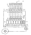
- FIG. 1 is a schematic block diagram showing the primary components of one embodiment of the modular, scalable, multi-function, power quality system for utility networks of this invention
- FIG. 2 is a circuit diagram of one embodiment of the modular, scalable, multi-function, power quality system shown in FIG. 1 showing in further detail the primary components of exemplarily unique function subsystems of this invention;
- FIG. 3 is a circuit diagram showing one example of a unique function subsystem configured as a VAR injector filter module
- FIG. 4 is a circuit diagram showing one example of a capacitive bank which may be coupled to the VAR injector filter module shown in FIG. 3 to provide additional capacitance for VAR injection;
- FIG. 5 is a circuit diagram showing one example of a unique function subsystem configured as a pre-charger module
- FIG. 6 is a circuit diagram showing one example of a unique function subsystem configured as a power regulation filter module
- FIG. 7 is a circuit diagram showing one example of a unique function subsystem configured as a series injector module
- FIG. 8 is a circuit diagram showing in further detail one example of then identical power module shown in FIGS. 1 and 2 ;
- FIGS. 9A-9B isare a schematic block diagram showing the primary components of one embodiment of the controller shown in FIGS. 1 and 2 .
- System 10 includes configurable frame 14 coupled to electrical input 42 and electrical output 46 .
- Electrical input 42 and electrical output 46 are coupled to electrical utility grid 44 .
- Frame 14 houses the various components of system 10 and provides protection from the user from electrical shock.
- System 10 also includes a plurality of functional slots 16 each preferably including receiving connector 20 coupled to frame 14 .
- the number of functional slots 16 in frame 14 is preferably defined by the customer based on the customer's specific modularity and functional needs.
- frame 14 includes eight functional slots 26 , 28 , 30 , 32 , 34 , 36 , 38 , and 40 each having a receiving connector 20 coupled thereto.
- System 10 also includes one or more unique function subsystems coupled to selected functional slots 16 .
- there are two unique function subsystems 24 and 26 although system 10 may have more or less than two functional subsystems as defined by the customer's requirements.
- Each unique function subsystem 24 , 26 includes one or more electrical components coupled to receiving connector 20 of selective functional slots 16 configured to define the functional capability associated with functional slots 16 , as will be discussed in further detail below.
- System 10 also includes a plurality of identical power modules 12 disposed in selected functional slots 16 of each of the one or more unique function subsystems.
- Identical power modules 12 are configured to provide multiple functions depending on which functional slot they are inserted.
- the number of functional slots 16 in frame 14 is defined by the customer based on the customer's specific modularity and functional needs.
- Each of power modules 12 include at least connector 21 configured to connect to a selected receiving connector 20 .
- identical power modules 46 , 48 , 50 , 52 , 54 , and 56 are connected by their respective connector 21 to receiving connector 22 of functional slots 26 , 28 , 30 , 32 , 34 , and 36 respectively of unique function subsystem 24 .
- identical power modules 58 and 62 are connected to functional slots 38 and 40 of unique function subsystem 26 .
- Receiving connectors 20 are mounted in frame 14 and couple the power and control signals from power modules 12 in functional slots 16 of the one or more unique function subsystems 24 and 26 to frame 14 .
- Receiving connectors 20 of functional slots 16 can be mounted on a back plane or can be individual connectors mounted in frame 14 .
- slot wiring 22 couples receiving connector 20 to unique function subsystem 24 and unique function subsystem 26 as shown.
- Controller 18 is coupled to each of power modules 12 and is configured to enable power modules 12 in the functional slots of the unique function subsystems to perform a predetermined function associated with electrical input 42 or electrical output 44 .
- Functional slots 16 are the physical locations that provide interface between power modules 12 and frame 14 . Functional slots 16 couple the control signals from controller 18 to power modules 12 enabling power modules 12 to process the appropriate power and function.
- Controller 18 controls the function of each of power module 12 in a manner consistent with their functional slot. Controller 18 is a system specific configuration that determines what slot forms what function at the time of assembly.
- Input electrical port 42 is a means of connecting system frame 14 to electrical power grid 44 .
- unique function subsystem 24 includes the necessary electrical components, such that when identical power modules 46 , 48 , 50 , 52 , 54 , and 56 are connected into functional slots 26 , 28 , 30 , 32 , 34 , and 36 respectively, controller 18 will cause power module 46 , 48 , 50 , 52 , 54 and 56 to perform a desired predetermined function associated with input electrical port 42 , e.g., voltage-ampere reactive (VAR) injection.
- VAR voltage-ampere reactive
- unique function subsystem 24 may be configured as VAR injector filter module 150 , FIG. 2 to provide clean power to electrical input 42 .
- VAR injector filter module 150 FIGS. 2 and 3 , preferably include includes filter 152 , FIG. 3 , comprised of inductors 154 , 156 , and capacitor 158 .
- PWM control signals output by controller 18 , FIG. 2 , by line 84 are input selected power modules 12 , e.g., power module 46 , as shown, as well as selected power modules 48 - 56 , FIG. 1 , at nodes 350 , 352 , 353 , and 354 , FIG. 8 , exemplary power module 12 in a manner to transfer bi-directional real and reactive power between input electrical port 42 , FIG. 2 , and capacitor bank sub-system 170 via power connector 370 , FIG. 8 .
- the detailed operation of power module 12 , FIG. 8 is discussed below.
- the bi-directional real and reactive power flow between electrical input port 42 , FIG. 2 , and power connector 370 , FIG.
- VAR injector filter module 150 may provide input harmonic current cancellation to electrical input 42 when controller 18 modulates the PWM control signals to the selected power modules 46 , 48 , 50 , 52 , 54 , and 56 such that controller 18 cancels harmonic currents which may flow between the grid 44 and load 47 .
- capacitive bank subsystem 170 is coupled to VAR injector filter module 150 .
- Capacitive bank subsystem 170 , FIG. 4 preferably includes a plurality of capacitors, e.g., 170 , 172 , 174 , and 176 , FIG. 4 , which provide additional capacitance needed for VAR injection.
- unique function subsystem 24 may be configured as a pre-charger module 80 , FIG. 2 , for pre-charging a DC bus of each of the plurality of identical power modules, e.g., DC bus 82 , of identical power modules 12 (shown in greater detail in FIG. 8 ).
- pre-charger module 80 FIG. 5
- pre-charger module 80 preferably includes contactor 86 comprised of switch 88 and control coil 90 and contact 92 comprised of switch 94 with control coil 96 .
- Pre-charger module 80 also includes resistor 93 .
- Pre-charger module 80 FIGS.
- control signals e.g., coil drive signals
- controller 18 receives control signals, e.g., coil drive signals, from controller 18 by line 84 , which are input at nodes 100 , 102 , 104 , and 106 , FIG. 5 , to control contactors 86 and 92 .
- Contactor 86 opens or closes switch 88 and contractor 92 opens or closes switch 94 .
- pre-charger module 80 provides power isolation.
- switch 94 is closed and switch 88 is open, pre-charger module 80 pre-charges DC buses 80 , FIG. 2 , of identical power modules 12 .
- Nodes 108 and 110 , FIG. 5 are coupled to electrical input 42 , FIG.
- Unique function circuit subsystem 26 is similar to unique function circuit subsystem 24 but include different components such that when identical power modules 58 , 60 are connected into functional slots 38 and 40 , controller 18 will cause power modules 38 , 40 to perform a different desired predetermined function associated with output electrical port 46 connected to electrical load 47 , e.g., power regulation.
- unique function subsystem 26 may be configured as power regulation filter module 198 .
- power regulation filter module 198 FIGS. 2 and 6
- filter 200 FIG. 6
- the PWM control signals output by controller 18 , FIG. 2 , by line 84 are input selected power modules 12 , e.g., to power module 58 , as shown, as well as power module 60 , FIG. 1 at nodes 350 , 352 , 353 , and 354 , FIG.
- exemplary power module 12 in a similar manner discussed above to transfer bi-directional real and reactive power capacitor bank sub-system 170 and electrical output port 46 via power connector 370 , FIG. 8 .
- the bi-directional real and reactive power flow between electrical output port 46 , FIG. 2 and power connector 370 , FIG. 8 has many harmonics that are filtered out by the power regulation filter module 198 , FIGS. 2 and 6 , to ensure energy coupled to electrical output port 46 is sinusoidal with suitably low harmonic content to provide filtered voltage to electrical output 46 .
- the un-filtered bi-directional real and reactive power flow are input at nodes 206 and 208 , FIG.
- power regulation filter module 198 may provide output voltage harmonic cancellation to electrical output 46 when controller 18 modulates the PWM signals to power modules 58 , 60 in a manner to cancel harmonic voltage distortion that may be present on the grid 44 from being presented to the load 47 .
- Unique function subsystem 26 , FIGS. 1 and 2 , for power regulation system may also include series injector module 250 , FIG. 2 , configured to inject regulator voltage to electrical output 46 to provide power regulation and provide by-pass protection during an overload or failure of system 10 .
- FIG. 7 shows a more detailed view of series injector module 250 .
- control signals from controller 18 , FIG. 2 , by lines 84 are input at nodes 254 , 256 , 258 , 260 , and 262 , FIG. 7 .
- Current signals are output at nodes 262 , 264 , 266 , and 268 by series injector 250 connected to lines 84 , FIG. 2 , and sensed by controller 18 .
- Series injector module 250 preferably includes silicon-controlled rectifier (SCR) 270 and transformer 272 which provides series voltage injection which is output at nodes 280 , 282 to electrical output 46 as shown in FIG. 2 .
- the input voltage from electrical input 42 is input at nodes 284 , 286 , FIGS. 2 and 7 .
- the determined regulated voltage output by power regulation filter module 198 , FIG. 2 of unique function subsystem 26 is input at nodes 300 , 302 .
- each of the identical power modules 12 includes a plurality of gate drives coupled to a plurality of switching transistors responsive to PWM control signals from the controller.
- FIG. 8 shows in further detail one example of a single power module 12 which is identical to all the power modules in the system, e.g., power modules 46 - 60 , FIG. 1 .
- power module 12 includes gate drives 362 , 364 , 366 , and 368 , coupled to switching transistors 370 , 372 , 374 , and 376 , respectively.
- switching transistors 370 , 372 , 374 , and 376 are insulated gate bi-polar transistors (IGBT) or similar type switching transistors.
- power modules 12 receive PWM signals from controller 18 by line 84 .
- the PWM control signals on line 84 are input to power module 12 , FIG. 8 , at nodes 350 , 352 , 354 and 356 .
- Output signals generated by power module 12 are output at nodes 358 , 360 are input to and sensed by controller 18 , FIG. 2 , by line 84 as shown.
- Power port 372 , FIGS. 2 and 8 may be coupled to other identical power modules by line 373 , FIG. 2 , as shown.
- Power port 370 , FIGS. 2 and 8 of power module 12 may be coupled to VAR injector module 150 by line 379 as shown.
- Power port 370 , FIGS. 2 and 8 of a different power module 12 may be coupled to power regulation filter module 198 by line 381 as shown.
- Power module 12 is typically coupled to 200 to 400 VDC, indicated at 402 .
- Controller 18 is preferably configured to sense the functional capability associated with each of the unique functional subsystems.
- controller 18 FIG. 1
- controller 18 is configured to generate PWM signals to each of the power modules to activate one or more of gate drives 362 , 364 , 366 , and 368 , FIG. 8 , to turn on or off switching transistors 370 , 372 , 374 , and 376 to define the functional capability of the functional slots of the unique function subsystems as discussed above.
- controller 18 includes analog conditioning circuit 400 responsive to inputs 402 .
- Analog conditioning circuit 400 provides input to ADC and multiplexor 404 .
- Controller 18 also preferably includes microprocessor 408 , e.g., a DSP chip or similar type chip, and PWM logic circuit 412 .
- PWM logic circuit 412 provides the PWM signals discussed above to the various power modules, in this example, indicated by power card 1 , power card 2 , power card 3 , power card 4 , power card 5 , power card 6 , power card 7 , and power card 8 , corresponding to the plurality of power modules 46 - 60 , FIG. 1 .
- Controller 18 also preferably includes digital input/output (I/O) buffer driver 450 which provides I/O signals by line 452 which is coupled to line 454 and output at node 456 . These I/O signals connect to at least nodes 102 - 108 , FIG. 5 , of pre-charger 80 . Node 470 , FIG. 10 , of controller 18 , receives input from various unique function subsystems discussed above with reference to one or more of FIGS. 1-9 . Thus, controller 18 , FIGS.
- FIGS. 1, 2 and 9 is configured to sense the functional capability associated with each of the unique functional subsystems.
- controller 18 may sense DC bus voltage of each of the power supply modules 12 , FIGS. 1, 2, and 8 , the current in each of the power modules 12 , the current and/or voltage from the electrical input 42 and electrical output 46 and/or the temperature of system 10 .
- FIGS. 1-9B The result is modular, scalable, multi-function, power quality system 10 for utility networks shown in one or more of FIGS. 1-9B provides a modular and scalable power conditioning system from identical modules which are connected to a configurable frame with function-specific slots. This enables a customer, such as an electrical utility grid network with multiple power conditioning needs, to purchase a plurality of identical power modules and a single system frame with multiple function-specific slots to create independent scaling of power and functionality.
- One or more embodiments of the modular, scalable, multi-function, power quality system for utility networks of this invention provides a modular and scalable power conditioning system that includes a plurality of identical power modules that are connected to a configurable frame having predetermined function-specific slots that define a predetermined function.
- a controller controls the function of the power modules in their function-specific slots such that they perform a desired predefined function.
- Such a design enables a customer, e.g., an electrical utility grid with multiple power conditioning needs, to purchase a plurality of identical power modules and a single system frame containing multiple function-specific slots.
- Such a design provides for independent scaling of power and functionality. The customer need only to estimate future power and functional needs and purchase a system with the appropriate number of pre-configured slots and a minimal set of identical power modules and populate the power modules in the appropriate functional slot. If greater function or power capability is needed, more power modules can be added.
Landscapes
- Engineering & Computer Science (AREA)
- Microelectronics & Electronic Packaging (AREA)
- Power Engineering (AREA)
- Inverter Devices (AREA)
- Physics & Mathematics (AREA)
- Electromagnetism (AREA)
- General Physics & Mathematics (AREA)
- Radar, Positioning & Navigation (AREA)
- Automation & Control Theory (AREA)
- Charge And Discharge Circuits For Batteries Or The Like (AREA)
Abstract
Description
Claims (32)
Priority Applications (5)
| Application Number | Priority Date | Filing Date | Title |
|---|---|---|---|
| US14/031,341 US9795048B2 (en) | 2013-09-19 | 2013-09-19 | Modular, scalable, multi-function, power quality system for utility networks |
| AU2014321674A AU2014321674B2 (en) | 2013-09-19 | 2014-09-08 | A modular, scalable, multi-function, power quality system for utility networks |
| EP14846190.8A EP3047349A4 (en) | 2013-09-19 | 2014-09-08 | A modular, scalable, multi-function, power quality system for utility networks |
| PCT/US2014/054532 WO2015041881A1 (en) | 2013-09-19 | 2014-09-08 | A modular, scalable, multi-function, power quality system for utility networks |
| US15/715,737 US20180084663A1 (en) | 2013-09-19 | 2017-09-26 | Modular, scalable, multi-function, power quality system for utility networks |
Applications Claiming Priority (1)
| Application Number | Priority Date | Filing Date | Title |
|---|---|---|---|
| US14/031,341 US9795048B2 (en) | 2013-09-19 | 2013-09-19 | Modular, scalable, multi-function, power quality system for utility networks |
Related Child Applications (1)
| Application Number | Title | Priority Date | Filing Date |
|---|---|---|---|
| US15/715,737 Continuation US20180084663A1 (en) | 2013-09-19 | 2017-09-26 | Modular, scalable, multi-function, power quality system for utility networks |
Publications (2)
| Publication Number | Publication Date |
|---|---|
| US20150081131A1 US20150081131A1 (en) | 2015-03-19 |
| US9795048B2 true US9795048B2 (en) | 2017-10-17 |
Family
ID=52668691
Family Applications (2)
| Application Number | Title | Priority Date | Filing Date |
|---|---|---|---|
| US14/031,341 Active 2035-02-12 US9795048B2 (en) | 2013-09-19 | 2013-09-19 | Modular, scalable, multi-function, power quality system for utility networks |
| US15/715,737 Abandoned US20180084663A1 (en) | 2013-09-19 | 2017-09-26 | Modular, scalable, multi-function, power quality system for utility networks |
Family Applications After (1)
| Application Number | Title | Priority Date | Filing Date |
|---|---|---|---|
| US15/715,737 Abandoned US20180084663A1 (en) | 2013-09-19 | 2017-09-26 | Modular, scalable, multi-function, power quality system for utility networks |
Country Status (4)
| Country | Link |
|---|---|
| US (2) | US9795048B2 (en) |
| EP (1) | EP3047349A4 (en) |
| AU (1) | AU2014321674B2 (en) |
| WO (1) | WO2015041881A1 (en) |
Cited By (2)
| Publication number | Priority date | Publication date | Assignee | Title |
|---|---|---|---|---|
| US20170025894A1 (en) * | 2015-07-04 | 2017-01-26 | Sunverge Energy, Inc. | Microgrid controller for distributed energy systems |
| US10622835B2 (en) | 2015-07-04 | 2020-04-14 | Sunverge Energy, Inc. | Distributed energy system edge unit |
Families Citing this family (1)
| Publication number | Priority date | Publication date | Assignee | Title |
|---|---|---|---|---|
| CN106253309B (en) * | 2016-08-31 | 2018-09-28 | 湖北华辰凯龙电力有限公司 | It is a kind of integrate the compensation of active dynamic filter, power factor regulation power factor controller |
Citations (30)
| Publication number | Priority date | Publication date | Assignee | Title |
|---|---|---|---|---|
| US4419619A (en) | 1981-09-18 | 1983-12-06 | Mcgraw-Edison Company | Microprocessor controlled voltage regulating transformer |
| US5283726A (en) * | 1991-12-20 | 1994-02-01 | Wilkerson A W | AC line current controller utilizing line connected inductance and DC voltage component |
| US5383090A (en) * | 1991-03-28 | 1995-01-17 | Dorma Gmbh & Co. Kg | Electrical energy distribution system |
| US5548203A (en) * | 1994-06-29 | 1996-08-20 | Electric Power Research Institute, Inc. | Capacitor polarity-based var correction controller for resonant line conditions and large amplitude line harmonics |
| US6075350A (en) | 1998-04-24 | 2000-06-13 | Lockheed Martin Energy Research Corporation | Power line conditioner using cascade multilevel inverters for voltage regulation, reactive power correction, and harmonic filtering |
| US6134124A (en) * | 1999-05-12 | 2000-10-17 | Abb Power T&D Company Inc. | Universal distributed-resource interface |
| US6191676B1 (en) * | 1994-10-21 | 2001-02-20 | Spinel Llc | Apparatus for suppressing nonlinear current drawing characteristics |
| US6327162B1 (en) | 1995-01-13 | 2001-12-04 | General Electric Company | Static series voltage regulator |
| US6404348B1 (en) | 1999-02-11 | 2002-06-11 | Power Quality Consultants, Inc. | Modular power quality monitoring device |
| US20030058618A1 (en) * | 2001-09-27 | 2003-03-27 | Joseph Soetemans | Method and apparatus for providing a common support services infrastructure for a network element |
| US6738692B2 (en) | 2001-06-25 | 2004-05-18 | Sustainable Energy Technologies | Modular, integrated power conversion and energy management system |
| US6861943B2 (en) * | 2001-09-27 | 2005-03-01 | Alcatel Canada Inc. | System and method for network element equipment status monitoring |
| US6917227B1 (en) | 2001-05-04 | 2005-07-12 | Ixys Corporation | Efficient gate driver for power device |
| US20050170678A1 (en) * | 2001-11-28 | 2005-08-04 | Donahue William F.Iv | Modular power distribution unit, module for the power distribution unit, and method of using the same |
| US7209477B2 (en) * | 2001-09-27 | 2007-04-24 | Alcatel Canada Inc. | Multi-subshelf control system and method for a network element |
| US20070242413A1 (en) * | 2003-12-19 | 2007-10-18 | Abb Technology Ltd | Power Capacitor |
| US7532490B2 (en) | 2006-08-14 | 2009-05-12 | General Electric Company | Converter topology and methods for interfacing an electrical machine to electrical power grid |
| WO2010000315A1 (en) | 2008-07-02 | 2010-01-07 | Vestas Wind Systems A/S | Modular converter system supporting harmonic suppression |
| US20100019742A1 (en) * | 2006-10-04 | 2010-01-28 | Lihua Li | Unified Control of Single and Three-Phase Power Converters |
| US20100290186A1 (en) * | 2009-05-15 | 2010-11-18 | Ruggedcom Inc. | Open Frame Electronic Chassis For Enclosed Modules |
| WO2011124223A2 (en) | 2010-04-06 | 2011-10-13 | Danfoss Drives A/S | Power quality improvement by active filter |
| US20120016531A1 (en) | 2010-07-16 | 2012-01-19 | Honeywell International Inc. | Method and system for power quality protection |
| US20120169300A1 (en) * | 2011-01-04 | 2012-07-05 | General Electric Company | Integrated electric meter with var capability |
| US8244406B2 (en) | 2009-04-17 | 2012-08-14 | Howard University | System and method of monitoring and optimizing power quality in a network |
| US20120310434A1 (en) | 2011-05-31 | 2012-12-06 | Cisco Technology, Inc. | Variable topology distributed intelligence for utility grid control operation services |
| WO2013000512A1 (en) | 2011-06-29 | 2013-01-03 | Abb Technology Ag | A rack for a modular voltage source converter and an insulation device |
| US20130099565A1 (en) | 2011-04-15 | 2013-04-25 | Deka Products Limited Partnership | Modular power conversion system |
| US20130121051A1 (en) | 2011-11-14 | 2013-05-16 | Rockwell Automation Technologies, Inc. | Dc pre-charge circuit |
| US20130322016A1 (en) * | 2012-05-30 | 2013-12-05 | Comprehensive Power, Inc. | Power management systems |
| US20140254223A1 (en) * | 2013-03-07 | 2014-09-11 | Rudolf Limpaecher | Method and system for a high speed soft-switching resonant converter |
Family Cites Families (1)
| Publication number | Priority date | Publication date | Assignee | Title |
|---|---|---|---|---|
| EP2196120A1 (en) * | 2008-07-01 | 2010-06-16 | Koninklijke Philips Electronics N.V. | Beater and mixing device with beater |
-
2013
- 2013-09-19 US US14/031,341 patent/US9795048B2/en active Active
-
2014
- 2014-09-08 AU AU2014321674A patent/AU2014321674B2/en not_active Ceased
- 2014-09-08 EP EP14846190.8A patent/EP3047349A4/en not_active Withdrawn
- 2014-09-08 WO PCT/US2014/054532 patent/WO2015041881A1/en active Application Filing
-
2017
- 2017-09-26 US US15/715,737 patent/US20180084663A1/en not_active Abandoned
Patent Citations (30)
| Publication number | Priority date | Publication date | Assignee | Title |
|---|---|---|---|---|
| US4419619A (en) | 1981-09-18 | 1983-12-06 | Mcgraw-Edison Company | Microprocessor controlled voltage regulating transformer |
| US5383090A (en) * | 1991-03-28 | 1995-01-17 | Dorma Gmbh & Co. Kg | Electrical energy distribution system |
| US5283726A (en) * | 1991-12-20 | 1994-02-01 | Wilkerson A W | AC line current controller utilizing line connected inductance and DC voltage component |
| US5548203A (en) * | 1994-06-29 | 1996-08-20 | Electric Power Research Institute, Inc. | Capacitor polarity-based var correction controller for resonant line conditions and large amplitude line harmonics |
| US6191676B1 (en) * | 1994-10-21 | 2001-02-20 | Spinel Llc | Apparatus for suppressing nonlinear current drawing characteristics |
| US6327162B1 (en) | 1995-01-13 | 2001-12-04 | General Electric Company | Static series voltage regulator |
| US6075350A (en) | 1998-04-24 | 2000-06-13 | Lockheed Martin Energy Research Corporation | Power line conditioner using cascade multilevel inverters for voltage regulation, reactive power correction, and harmonic filtering |
| US6404348B1 (en) | 1999-02-11 | 2002-06-11 | Power Quality Consultants, Inc. | Modular power quality monitoring device |
| US6134124A (en) * | 1999-05-12 | 2000-10-17 | Abb Power T&D Company Inc. | Universal distributed-resource interface |
| US6917227B1 (en) | 2001-05-04 | 2005-07-12 | Ixys Corporation | Efficient gate driver for power device |
| US6738692B2 (en) | 2001-06-25 | 2004-05-18 | Sustainable Energy Technologies | Modular, integrated power conversion and energy management system |
| US7209477B2 (en) * | 2001-09-27 | 2007-04-24 | Alcatel Canada Inc. | Multi-subshelf control system and method for a network element |
| US20030058618A1 (en) * | 2001-09-27 | 2003-03-27 | Joseph Soetemans | Method and apparatus for providing a common support services infrastructure for a network element |
| US6861943B2 (en) * | 2001-09-27 | 2005-03-01 | Alcatel Canada Inc. | System and method for network element equipment status monitoring |
| US20050170678A1 (en) * | 2001-11-28 | 2005-08-04 | Donahue William F.Iv | Modular power distribution unit, module for the power distribution unit, and method of using the same |
| US20070242413A1 (en) * | 2003-12-19 | 2007-10-18 | Abb Technology Ltd | Power Capacitor |
| US7532490B2 (en) | 2006-08-14 | 2009-05-12 | General Electric Company | Converter topology and methods for interfacing an electrical machine to electrical power grid |
| US20100019742A1 (en) * | 2006-10-04 | 2010-01-28 | Lihua Li | Unified Control of Single and Three-Phase Power Converters |
| WO2010000315A1 (en) | 2008-07-02 | 2010-01-07 | Vestas Wind Systems A/S | Modular converter system supporting harmonic suppression |
| US8244406B2 (en) | 2009-04-17 | 2012-08-14 | Howard University | System and method of monitoring and optimizing power quality in a network |
| US20100290186A1 (en) * | 2009-05-15 | 2010-11-18 | Ruggedcom Inc. | Open Frame Electronic Chassis For Enclosed Modules |
| WO2011124223A2 (en) | 2010-04-06 | 2011-10-13 | Danfoss Drives A/S | Power quality improvement by active filter |
| US20120016531A1 (en) | 2010-07-16 | 2012-01-19 | Honeywell International Inc. | Method and system for power quality protection |
| US20120169300A1 (en) * | 2011-01-04 | 2012-07-05 | General Electric Company | Integrated electric meter with var capability |
| US20130099565A1 (en) | 2011-04-15 | 2013-04-25 | Deka Products Limited Partnership | Modular power conversion system |
| US20120310434A1 (en) | 2011-05-31 | 2012-12-06 | Cisco Technology, Inc. | Variable topology distributed intelligence for utility grid control operation services |
| WO2013000512A1 (en) | 2011-06-29 | 2013-01-03 | Abb Technology Ag | A rack for a modular voltage source converter and an insulation device |
| US20130121051A1 (en) | 2011-11-14 | 2013-05-16 | Rockwell Automation Technologies, Inc. | Dc pre-charge circuit |
| US20130322016A1 (en) * | 2012-05-30 | 2013-12-05 | Comprehensive Power, Inc. | Power management systems |
| US20140254223A1 (en) * | 2013-03-07 | 2014-09-11 | Rudolf Limpaecher | Method and system for a high speed soft-switching resonant converter |
Non-Patent Citations (2)
| Title |
|---|
| International Searching Authority, Written Opinion for International Application No. PCT/US2014/054532, dated Dec. 18, 2014, 10 pgs. |
| Ohrtishi et al., "Utility Power Quality Control by Using a Three Phase Inverter Module", IEEE, 2007, pp. 3073-3078. |
Cited By (7)
| Publication number | Priority date | Publication date | Assignee | Title |
|---|---|---|---|---|
| US20170025894A1 (en) * | 2015-07-04 | 2017-01-26 | Sunverge Energy, Inc. | Microgrid controller for distributed energy systems |
| US10622835B2 (en) | 2015-07-04 | 2020-04-14 | Sunverge Energy, Inc. | Distributed energy system edge unit |
| US10622834B2 (en) | 2015-07-04 | 2020-04-14 | Sunverge Energy, Inc. | Virtual power plant |
| US10635058B2 (en) | 2015-07-04 | 2020-04-28 | Sunverge Energy, Inc. | Microgrid controller for distributed energy systems |
| US11258301B2 (en) | 2015-07-04 | 2022-02-22 | Sunverge Energy, Inc. | Virtual power plant |
| US11271425B2 (en) | 2015-07-04 | 2022-03-08 | Sunverge Energy, Inc. | Distributed energy system edge unit |
| US11749990B2 (en) | 2015-07-04 | 2023-09-05 | Sunverge Energy, Inc. | Distributed energy system edge unit |
Also Published As
| Publication number | Publication date |
|---|---|
| EP3047349A4 (en) | 2017-08-16 |
| WO2015041881A1 (en) | 2015-03-26 |
| AU2014321674B2 (en) | 2017-11-09 |
| US20150081131A1 (en) | 2015-03-19 |
| EP3047349A1 (en) | 2016-07-27 |
| US20180084663A1 (en) | 2018-03-22 |
| AU2014321674A1 (en) | 2016-04-07 |
Similar Documents
| Publication | Publication Date | Title |
|---|---|---|
| US10811988B2 (en) | Power management utilizing synchronous common coupling | |
| US10536027B2 (en) | UPS with multiple independent static switches | |
| US9673625B2 (en) | Uninterruptible power supply apparatus | |
| EP2670013B1 (en) | Current flow controller | |
| US20180084663A1 (en) | Modular, scalable, multi-function, power quality system for utility networks | |
| KR20100017730A (en) | Common mode filter system and method for a solar power inverter | |
| MXPA01010269A (en) | Universal harmonic mitigating system. | |
| CN106469912B (en) | Static passive compensation device and its operating method | |
| EP2392065A1 (en) | System and method for limiting losses in an uninterruptible power supply | |
| CN104160351B (en) | Diversity switch | |
| CN104782023A (en) | UPS systems and methods using UPS modules with differential mode inductor coupling | |
| WO2016176256A1 (en) | Photovoltaic dc power distribution system | |
| JPH05503201A (en) | Device for balanced three-phase AC power supply for computers with variable DC loads | |
| NL2019182B1 (en) | Power grid and flexible current transmission system forming part thereof | |
| US10075060B2 (en) | Electrical assembly comprising filter device for improving quality of electricity | |
| KR20210138662A (en) | Multiport Power Converter Unit | |
| Benoudjafer et al. | Hybrid shunt active filter: Impact of the network’s impedance on the filtering characteristic | |
| Ambatkar et al. | Study Of Different Passive Filter-A Review | |
| KR101283554B1 (en) | Inverter system with filter automatically varying according to control mode | |
| Al Dubaikel et al. | Comparison between transformer-based Vs. transformer-less UPS systems | |
| US11757302B2 (en) | Power supply assembly and switch assembly | |
| Singh et al. | Passive hybrid filter for varying rectifier loads | |
| Mishra et al. | Load compensation for single phase system using series active filter | |
| US6054781A (en) | Voltage bus filtering scheme for a battery power plant | |
| CN206620059U (en) | Rectifier cabinet and frequency converter |
Legal Events
| Date | Code | Title | Description |
|---|---|---|---|
| AS | Assignment |
Owner name: GRIDCO INC., MASSACHUSETTS Free format text: ASSIGNMENT OF ASSIGNORS INTEREST;ASSIGNORS:SIMONELLI, JAMES;PATEL, NAIMISH;WU, JIA;REEL/FRAME:032818/0022 Effective date: 20140502 |
|
| STCF | Information on status: patent grant |
Free format text: PATENTED CASE |
|
| AS | Assignment |
Owner name: PACIFIC WESTERN BANK, NORTH CAROLINA Free format text: SECURITY INTEREST;ASSIGNOR:GRIDCO, INC.;REEL/FRAME:043914/0675 Effective date: 20170926 |
|
| AS | Assignment |
Owner name: GRIDCO INC., MASSACHUSETTS Free format text: RELEASE BY SECURED PARTY;ASSIGNOR:PACIFIC WESTERN BANK;REEL/FRAME:046611/0285 Effective date: 20180724 |
|
| AS | Assignment |
Owner name: VARENTEC, INC., CALIFORNIA Free format text: ASSIGNMENT OF ASSIGNORS INTEREST;ASSIGNOR:GRIDCO, INC.;REEL/FRAME:046744/0922 Effective date: 20180702 |
|
| AS | Assignment |
Owner name: WINDSAIL CAPITAL FUND, L.P., MASSACHUSETTS Free format text: SECURITY INTEREST;ASSIGNOR:VARENTEC, INC.;REEL/FRAME:050869/0593 Effective date: 20191030 |
|
| AS | Assignment |
Owner name: VARENTEC, INC., CALIFORNIA Free format text: RELEASE BY SECURED PARTY;ASSIGNOR:WINDSAIL CAPITAL FUND, L.P., AS AGENT;REEL/FRAME:055238/0621 Effective date: 20210210 |
|
| AS | Assignment |
Owner name: SENTIENT ENERGY TECHNOLOGY, LLC, KANSAS Free format text: ASSIGNMENT OF ASSIGNORS INTEREST;ASSIGNOR:VARENTEC, INC.;REEL/FRAME:055351/0601 Effective date: 20210209 |
|
| MAFP | Maintenance fee payment |
Free format text: PAYMENT OF MAINTENANCE FEE, 4TH YR, SMALL ENTITY (ORIGINAL EVENT CODE: M2551); ENTITY STATUS OF PATENT OWNER: SMALL ENTITY Year of fee payment: 4 |
|
| FEPP | Fee payment procedure |
Free format text: ENTITY STATUS SET TO UNDISCOUNTED (ORIGINAL EVENT CODE: BIG.); ENTITY STATUS OF PATENT OWNER: LARGE ENTITY |