US9728974B2 - Renewable energy site reactive power control - Google Patents
Renewable energy site reactive power control Download PDFInfo
- Publication number
- US9728974B2 US9728974B2 US14/050,928 US201314050928A US9728974B2 US 9728974 B2 US9728974 B2 US 9728974B2 US 201314050928 A US201314050928 A US 201314050928A US 9728974 B2 US9728974 B2 US 9728974B2
- Authority
- US
- United States
- Prior art keywords
- reactive power
- site
- error
- fbk
- voltage
- Prior art date
- Legal status (The legal status is an assumption and is not a legal conclusion. Google has not performed a legal analysis and makes no representation as to the accuracy of the status listed.)
- Active, expires
Links
- 238000000034 method Methods 0.000 claims abstract description 59
- 230000007704 transition Effects 0.000 claims description 24
- 229920006395 saturated elastomer Polymers 0.000 claims description 14
- 238000012886 linear function Methods 0.000 claims description 5
- ZXVONLUNISGICL-UHFFFAOYSA-N 4,6-dinitro-o-cresol Chemical compound CC1=CC([N+]([O-])=O)=CC([N+]([O-])=O)=C1O ZXVONLUNISGICL-UHFFFAOYSA-N 0.000 claims description 3
- 238000004891 communication Methods 0.000 claims description 3
- 238000004590 computer program Methods 0.000 abstract description 4
- 230000001627 detrimental effect Effects 0.000 abstract description 3
- 230000003247 decreasing effect Effects 0.000 abstract description 2
- 230000007246 mechanism Effects 0.000 abstract description 2
- 238000012546 transfer Methods 0.000 abstract description 2
- 238000004364 calculation method Methods 0.000 description 32
- 238000010586 diagram Methods 0.000 description 11
- 230000008569 process Effects 0.000 description 10
- 230000010354 integration Effects 0.000 description 6
- 238000012545 processing Methods 0.000 description 4
- 238000005315 distribution function Methods 0.000 description 3
- 230000006870 function Effects 0.000 description 3
- 230000033228 biological regulation Effects 0.000 description 2
- 238000006243 chemical reaction Methods 0.000 description 2
- 230000001419 dependent effect Effects 0.000 description 2
- 238000012986 modification Methods 0.000 description 2
- 230000004048 modification Effects 0.000 description 2
- 230000004044 response Effects 0.000 description 2
- 230000009286 beneficial effect Effects 0.000 description 1
- 230000008901 benefit Effects 0.000 description 1
- 230000008859 change Effects 0.000 description 1
- 230000007423 decrease Effects 0.000 description 1
- 238000013461 design Methods 0.000 description 1
- 230000008030 elimination Effects 0.000 description 1
- 238000003379 elimination reaction Methods 0.000 description 1
- 230000006872 improvement Effects 0.000 description 1
- 230000000116 mitigating effect Effects 0.000 description 1
- 230000008520 organization Effects 0.000 description 1
- 230000010355 oscillation Effects 0.000 description 1
- 238000004806 packaging method and process Methods 0.000 description 1
- 230000003068 static effect Effects 0.000 description 1
- 238000006467 substitution reaction Methods 0.000 description 1
- 230000001502 supplementing effect Effects 0.000 description 1
- 230000001052 transient effect Effects 0.000 description 1
Images


Classifications
-
- H—ELECTRICITY
- H02—GENERATION; CONVERSION OR DISTRIBUTION OF ELECTRIC POWER
- H02J—CIRCUIT ARRANGEMENTS OR SYSTEMS FOR SUPPLYING OR DISTRIBUTING ELECTRIC POWER; SYSTEMS FOR STORING ELECTRIC ENERGY
- H02J3/00—Circuit arrangements for ac mains or ac distribution networks
- H02J3/38—Arrangements for parallely feeding a single network by two or more generators, converters or transformers
- H02J3/46—Controlling of the sharing of output between the generators, converters, or transformers
- H02J3/50—Controlling the sharing of the out-of-phase component
-
- H—ELECTRICITY
- H02—GENERATION; CONVERSION OR DISTRIBUTION OF ELECTRIC POWER
- H02J—CIRCUIT ARRANGEMENTS OR SYSTEMS FOR SUPPLYING OR DISTRIBUTING ELECTRIC POWER; SYSTEMS FOR STORING ELECTRIC ENERGY
- H02J3/00—Circuit arrangements for ac mains or ac distribution networks
- H02J3/18—Arrangements for adjusting, eliminating or compensating reactive power in networks
-
- H—ELECTRICITY
- H02—GENERATION; CONVERSION OR DISTRIBUTION OF ELECTRIC POWER
- H02J—CIRCUIT ARRANGEMENTS OR SYSTEMS FOR SUPPLYING OR DISTRIBUTING ELECTRIC POWER; SYSTEMS FOR STORING ELECTRIC ENERGY
- H02J3/00—Circuit arrangements for ac mains or ac distribution networks
- H02J3/38—Arrangements for parallely feeding a single network by two or more generators, converters or transformers
- H02J3/381—Dispersed generators
-
- H—ELECTRICITY
- H02—GENERATION; CONVERSION OR DISTRIBUTION OF ELECTRIC POWER
- H02J—CIRCUIT ARRANGEMENTS OR SYSTEMS FOR SUPPLYING OR DISTRIBUTING ELECTRIC POWER; SYSTEMS FOR STORING ELECTRIC ENERGY
- H02J3/00—Circuit arrangements for ac mains or ac distribution networks
- H02J3/38—Arrangements for parallely feeding a single network by two or more generators, converters or transformers
- H02J3/46—Controlling of the sharing of output between the generators, converters, or transformers
-
- H—ELECTRICITY
- H02—GENERATION; CONVERSION OR DISTRIBUTION OF ELECTRIC POWER
- H02J—CIRCUIT ARRANGEMENTS OR SYSTEMS FOR SUPPLYING OR DISTRIBUTING ELECTRIC POWER; SYSTEMS FOR STORING ELECTRIC ENERGY
- H02J3/00—Circuit arrangements for ac mains or ac distribution networks
- H02J3/12—Circuit arrangements for ac mains or ac distribution networks for adjusting voltage in ac networks by changing a characteristic of the network load
- H02J3/16—Circuit arrangements for ac mains or ac distribution networks for adjusting voltage in ac networks by changing a characteristic of the network load by adjustment of reactive power
-
- H—ELECTRICITY
- H02—GENERATION; CONVERSION OR DISTRIBUTION OF ELECTRIC POWER
- H02J—CIRCUIT ARRANGEMENTS OR SYSTEMS FOR SUPPLYING OR DISTRIBUTING ELECTRIC POWER; SYSTEMS FOR STORING ELECTRIC ENERGY
- H02J3/00—Circuit arrangements for ac mains or ac distribution networks
- H02J3/18—Arrangements for adjusting, eliminating or compensating reactive power in networks
- H02J3/1821—Arrangements for adjusting, eliminating or compensating reactive power in networks using shunt compensators
- H02J3/1835—Arrangements for adjusting, eliminating or compensating reactive power in networks using shunt compensators with stepless control
- H02J3/1842—Arrangements for adjusting, eliminating or compensating reactive power in networks using shunt compensators with stepless control wherein at least one reactive element is actively controlled by a bridge converter, e.g. active filters
-
- H—ELECTRICITY
- H02—GENERATION; CONVERSION OR DISTRIBUTION OF ELECTRIC POWER
- H02M—APPARATUS FOR CONVERSION BETWEEN AC AND AC, BETWEEN AC AND DC, OR BETWEEN DC AND DC, AND FOR USE WITH MAINS OR SIMILAR POWER SUPPLY SYSTEMS; CONVERSION OF DC OR AC INPUT POWER INTO SURGE OUTPUT POWER; CONTROL OR REGULATION THEREOF
- H02M1/00—Details of apparatus for conversion
- H02M1/42—Circuits or arrangements for compensating for or adjusting power factor in converters or inverters
- H02M1/4208—Arrangements for improving power factor of AC input
- H02M1/4233—Arrangements for improving power factor of AC input using a bridge converter comprising active switches
-
- Y—GENERAL TAGGING OF NEW TECHNOLOGICAL DEVELOPMENTS; GENERAL TAGGING OF CROSS-SECTIONAL TECHNOLOGIES SPANNING OVER SEVERAL SECTIONS OF THE IPC; TECHNICAL SUBJECTS COVERED BY FORMER USPC CROSS-REFERENCE ART COLLECTIONS [XRACs] AND DIGESTS
- Y02—TECHNOLOGIES OR APPLICATIONS FOR MITIGATION OR ADAPTATION AGAINST CLIMATE CHANGE
- Y02B—CLIMATE CHANGE MITIGATION TECHNOLOGIES RELATED TO BUILDINGS, e.g. HOUSING, HOUSE APPLIANCES OR RELATED END-USER APPLICATIONS
- Y02B70/00—Technologies for an efficient end-user side electric power management and consumption
- Y02B70/10—Technologies improving the efficiency by using switched-mode power supplies [SMPS], i.e. efficient power electronics conversion e.g. power factor correction or reduction of losses in power supplies or efficient standby modes
-
- Y02B70/126—
-
- Y—GENERAL TAGGING OF NEW TECHNOLOGICAL DEVELOPMENTS; GENERAL TAGGING OF CROSS-SECTIONAL TECHNOLOGIES SPANNING OVER SEVERAL SECTIONS OF THE IPC; TECHNICAL SUBJECTS COVERED BY FORMER USPC CROSS-REFERENCE ART COLLECTIONS [XRACs] AND DIGESTS
- Y02—TECHNOLOGIES OR APPLICATIONS FOR MITIGATION OR ADAPTATION AGAINST CLIMATE CHANGE
- Y02E—REDUCTION OF GREENHOUSE GAS [GHG] EMISSIONS, RELATED TO ENERGY GENERATION, TRANSMISSION OR DISTRIBUTION
- Y02E40/00—Technologies for an efficient electrical power generation, transmission or distribution
- Y02E40/20—Active power filtering [APF]
-
- Y02E40/22—
-
- Y—GENERAL TAGGING OF NEW TECHNOLOGICAL DEVELOPMENTS; GENERAL TAGGING OF CROSS-SECTIONAL TECHNOLOGIES SPANNING OVER SEVERAL SECTIONS OF THE IPC; TECHNICAL SUBJECTS COVERED BY FORMER USPC CROSS-REFERENCE ART COLLECTIONS [XRACs] AND DIGESTS
- Y02—TECHNOLOGIES OR APPLICATIONS FOR MITIGATION OR ADAPTATION AGAINST CLIMATE CHANGE
- Y02E—REDUCTION OF GREENHOUSE GAS [GHG] EMISSIONS, RELATED TO ENERGY GENERATION, TRANSMISSION OR DISTRIBUTION
- Y02E40/00—Technologies for an efficient electrical power generation, transmission or distribution
- Y02E40/30—Reactive power compensation
-
- Y02E40/34—
-
- Y10T307/549—
Definitions
- the present invention relates to control of reactive power at a renewable energy site. More particularly, the present invention relates to improvements on traditional renewable energy site reactive power and voltage control systems subject to utility voltage and reactive power limits and significant control loop delay.
- Renewable energy sites are typically composed of multiple power conversion devices connected in parallel generating fixed frequency AC power to a grid.
- the devices are typically AC-AC or DC-AC inverters.
- Inverters are designed to extract maximum power from the renewable power supply, subject to a real power limit reference and often, a reactive power or voltage command.
- a typical reactive power control system measures site total power feedback, reactive power and site voltage to actively control them.
- the site control loop consists of commands from the controller to the inverters and feedbacks from the inverters or a utility meter to the site controller.
- Reactive power control runs concurrently and relatively independently of real power control.
- the site controller typically generates a site level reactive power command and divides this by the number of online inverters to obtain individual inverter commands.
- a reactive power controller regulates site voltage or power factor, but not both at once since voltage and reactive power are mutually dependent.
- reactive power and voltage commands are subject to site voltage and power factor operating limits. Local reactive power controllers residing in inverters are typically much faster than the remote site control loop. Therefore it is important to implement as much control functionality by the inverter itself, if possible.
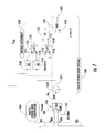
- the site control loop 10 consists of commands 23 from the controller 12 to the inverters 18 and feedbacks 21 from the inverters 18 or a utility meter 14 back to the site controller 12 .
- the inverters 18 are connected to a power source 16 such as a photovoltaic (PV) module, and a step-up transformer 20 may intervene between the inverters 18 and the power meter 14 .
- a point-of-control (POC) 15 is located next to the power meter 14 before the point of interconnection (POI) 17 with the utility.
- the traditional controller is composed of an inner voltage control loop and an outer reactive power loop.
- FIG. 2 shows an example of a traditional controller 30 .
- the inner voltage loop generates a reactive power command for the site (QCOM SITE ) 59 that may be converted to a reactive power command for each inverter (QCOM INVERTER ) 65 by division 64 by the number of inverters online 61 .
- QCOM INVERTER 65 maintains voltage at either a fixed voltage reference (V REF ) 41 , or a dynamic voltage reference (V COM ) 39 .
- the choice of voltage reference 45 is determined by the reactive power mode 42 : voltage control (V REF 41 ) or power factor control (V COM 39 ).
- Power factor control feeds the error (Q ERR ) 37 resulting from subtraction 32 of the reactive power feedback (Q FBK ) 31 from the sum of the reactive power compensation (Q COMP ) 35 and the reactive power reference (Q REF ) 33 (generated from a power factor reference) into a PI controller 38 to generate the dynamic voltage reference (V COM ) 39 .
- this controller offers a way to control voltage or power factor, depending on the reactive power mode.
- the voltage reference 45 is subject to voltage limits 46 , and the voltage feedback 49 is subtracted 48 from the limited voltage reference 47 to generate a voltage error (V ERR ) 51 .
- the voltage error (V ERR ) 51 is fed into a PI controller 52 to generate a reactive power command 55 which is subject to limits 56 before the site reactive power command (QCOM SITE ) 59 is generated.
- the present invention provides an improved method, computer program product, controller device, and system for reactive power control at a renewable energy site.
- the present invention addresses dynamic performance problems associated with significant control loop delay and the changing modes of operation required to meet utility voltage and reactive power constraints.
- Key elements include a reactive power control term based on the sum of a single integrator and reactive power compensation term, an integrator anti-windup mechanism based on the status of individual inverters, a means for decreasing detrimental effects of loop delay during reactive power reference changes, and a means of implementing voltage and power factor limits with smooth transfer between reactive power operating regions.
- Reactive power compensation which bypasses the control loop and its susceptibility to loop delay.
- a reactive power compensation term enables the controller to obtain faster dynamic performance, while still maintaining zero steady-state error.
- FIG. 3 shows a high-level summary of the present invention as embodied in an improved reactive power controller 100 .
- the reactive power controller 100 calculates 120 a voltage (V) and reactive power (Q) error and threshold error based in part on one or more or all of the following six data inputs: reactive power reference (Q REF ) 309 , reactive power feedback (Q FBK ) 411 , reactive power upper and lower limits (Q LIMIT ) 105 , voltage reference (V REF ) 633 , voltage feedback (V FBK ) 511 , and voltage upper and lower limits (V LIMIT ) 115 .
- Q REF reactive power reference
- Q FBK reactive power feedback
- Q LIMIT reactive power upper and lower limits
- a linear switch 970 can be used to determine the transition between power factor and voltage control modes, thereby determining whether the error 995 fed to the integrator 1000 is the reactive power error 895 or voltage error 885 .
- the linear switch 970 transition rate is determined by the reactive power slew (Q SLEW ) 855 .
- the integral calculator 1000 calculates a reactive power integral 1085 based on the error 995 , and the reactive power integral 1085 is summed 1210 with a reactive power compensation term (Q COMP ) 331 to generate a site-wide reactive power command (QCOM SITE ) 1295 .
- the reactive power command (QCOM SITE ) is distributed 2000 based on inverter reactive power feedback (INV.Q FBK ) 2105 to generate an inverter reactive power command (Inv.Q COMM ) 2151 .
- the reactive power distribution 2000 also increments a counter (NumQFree) 2255 which indicates the number of inverters producing less than maximum reactive power, which is used to determine the integral.
- the present invention uses a reactive power distribution function which computes individual inverter reactive power commands from the site total reactive power command.
- the site total reactive power command can be distributed or divided evenly among all or some of the inverters or can be distributed or divided unevenly among all or some of the inverters.
- One embodiment of the invention is a method for reactive power control for a renewable energy site that comprises one or more inverters, comprising: (a) providing machine-readable data related to a renewable energy site to at least one processor, wherein the machine-readable data comprises reactive power feedback (Q FBK ), reactive power upper (Q_UL) and lower (Q_LL) limits, a voltage reference (SiteVRef), voltage feedback (V FBK ), voltage upper (V_UL) and lower (V_LL) limits, a power factor reference (PF REF ) and a power feedback P FBK ; and (b) performing the following steps through the at least one processor: (1) calculating at least one of the following sources of error: (aa) a reactive power error (SiteQErr) based in part on Q FBK and P FBK ; (bb) a gain-multiplied voltage threshold error based in part on V FBK , V_UL, and V_LL; (cc) voltage error (SiteVErr) based in part on
- Another embodiment of the invention is a computer-readable medium including instructions that, when executed on a computer, cause a computer to provide the machine-readable data to the at least one processor and perform the steps described above through the at least one processor.
- a reactive power controller device comprising at least one processor, a form of computer-readable memory; and a set of computer-executable instructions configured to provide the machine readable data to the least one processor and perform the steps described above using the at least one processor.
- Another embodiment of the invention is a system comprising the reactive power controller device above comprising one or more inverters in a two-way communication with the reactive power controller through a network.
- the machine-readable data further comprises inverter power feedbacks (Inv.P FBK ) and the at least one processor distributes Q COM to individual inverters based on the inverter power feedbacks (Inv.P FBK ) by generating an inverter reactive power command (Inv[x].QCom[k]).
- Inv.P FBK inverter power feedbacks
- the at least one processor distributes Q COM to individual inverters based on the inverter power feedbacks (Inv.P FBK ) by generating an inverter reactive power command (Inv[x].QCom[k]).
- FIG. 1 is a schematic diagram showing an embodiment of a reactive power control system with four inverters.
- FIG. 2 is a block diagram showing a traditional reactive power controller.
- FIG. 3 is a block diagram showing an overview of an embodiment of an improved reactive power controller according to the invention.
- FIG. 4 is a block diagram showing an overview of an embodiment of the Site Reactive Power Compensation Control according to the invention.
- FIG. 5 is a block diagram showing embodiments of the Reactive Power Compensation (Feed-forward Term) Calculation and the Reactive Power Error Calculation according to the invention.
- FIG. 6 is a block diagram showing embodiments of the Voltage Threshold Error Calculation, the Voltage Error Calculation, and the Reactive Power Threshold Error Calculation according to the invention
- FIG. 7 is a block diagram showing embodiments of the Error Integral Calculation with Integral Anti-Windup according to the invention.
- FIG. 8 is a block diagram showing an embodiment of the Inverter Reactive Power Command Distribution.
- FIG. 9 is a schematic diagram showing an embodiment of a system for reactive power control according to the invention wherein a main site controller is configured for controlling a plurality of inverters through a network.
- Power factor control a closed loop regulator which controls site power factor without exceeding site voltage thresholds
- Voltage control a closed loop regulator which controls site voltage without exceeding site power factor thresholds.
- embodiments of the invention provide for threshold control wherein reactive power limits are imposed during voltage control and voltage limits are imposed during reactive power control.
- the invention provides a site-wide reactive power command comprised of a sum of a reactive power feed-forward or compensation term and an integrator term, which is distributed among inverters.
- the feed-forward term is a linear function of site real power feedback.
- particular embodiments of the present invention provide a means of smoothly transitioning between control modes, such as a linear switch with fixed transition time.
- the present invention comprises the feature of Integrator anti-windup based on either an upper limit computed at least partly from the maximum feedback power, or windup enabled logic based on the number of saturated inverters.
- the present invention provides loop delay compensation implemented by:
- Specific embodiments of the invention provide for a method for reactive power control for a renewable energy site that comprises one or more inverters, the method comprising: (a) determining a site-wide reactive power command comprised by a sum of a reactive power feedforward or compensation term and an integrator term; and (b) distributing the site-wide reactive power command among inverters.
- a reactive power command can be divided by the number of inverters to determine an inverter-specific reactive power command.
- Such methods can be configured such that the feedforward term is a linear function of site real power feedback.
- the determining of the site-wide reactive power command can be based on a power factor control subject to voltage threshold control or is based on a voltage control subject to power factor threshold control.
- the determining of the site-wide reactive power command can involve choosing between a power factor control mode and a voltage control mode and can be performed using a linear switch block with fixed transition time to transition between the power factor control and voltage modes.
- Such methods can also comprise integrator anti-windup for example based on either an upper limit computed at least partly from the maximum feedback power, or windup enabled logic based on a number of saturated inverters.
- Any of the methods of the invention can further comprise providing for LoopDelay compensation by: (a) comparing a present inverter reactive power feedback signal with a corresponding reactive power reference generated LoopDelay seconds prior to determine if an inverter is saturated, and (b) subtracting present inverter feedback signal from a reference generated LoopDelay seconds prior to compute an integration error term.
- Embodiments of the invention further provide for a method for reactive power control for a renewable energy site that comprises one or more inverters, the method comprising any one or more of the following steps in any combination:
- the listed references and limits provided in this specification are provided by a site operator who configures the site controller.
- Q COMP is a linear function of site real power feedback (P FBK ) and is calculated by adding a reactive power offset (LRPCoffset) to the product of a reactive power gain multiplied by the power feedback (P FBK ).
- the data provided in embodiments of the invention can comprise inverter power feedbacks (Inv.P FBK ) and can be configured such that the distributing of Q COM to the individual inverters is based on the inverter power feedbacks (Inv.P FBK ) by generating an inverter reactive power command (Inv[x].QCom[k]).
- Inv.P FBK inverter power feedbacks
- Inv[x].QCom[k] inverter reactive power command
- the SiteQErr can be calculated:
- SiteQrefGain - sign ⁇ ( PF ref ) ⁇ 1 PF ref - 1
- Methods of the invention can comprise choosing the power factor control mode and wherein when Q FBK is within Q_UL and Q_LL, the source of error is calculated as SiteVErr, or wherein when Q FBK exceeds Q_UL or Q_LL, the source of the error is calculated as the gain-multiplied reactive power threshold error which is a reactive power threshold error multiplied by gain K IQ .
- methods can comprise choosing the voltage control mode and wherein when V FBK is within V_UL and V_LL, the source of the error is calculated as SiteQErr, or wherein when V FBK exceeds V_UL and V_LL, the source of the error is calculated as the gain-multiplied voltage threshold error which is a voltage threshold error multiplied by gain K IV .
- Loop delay compensation can for example be implemented by comparing a present inverter reactive power feedback signal with a corresponding reactive power reference generated LoopDelay seconds prior to determine if an inverter is saturated or by subtracting present inverter feedback signal from a corresponding reference generated LoopDelay seconds prior to compute an integration error term.
- loop delay compensation can be performed in a manner such that (a) SiteQRefGain[k] is offset by a LoopDelay term D and SiteQRefGain[k] is replaced by SiteQRefGain[k-D], or such that (b) Inv[x].QCom[k] is offset by a LoopDelay term D and Inv[x].QCom[k] is replaced by Inv[x].QCom[k-D].
- Such embodiments can comprise integrator anti-windup based on either an upper limit computed at least partly from the maximum feedback power, or windup enabled logic based on a number of saturated inverters.
- Such embodiments can comprise choosing between a power factor control mode and a voltage control mode is performed using a linear switch block with fixed transition time to transition between the power factor control and voltage modes.
- switch is limited to between 0 and 1.
- the data provided according to methods of the invention can include a reactive power output (Inv[x].Q FBK ) and a new calculated integrator value (Q ERR ), where a counter (NumQFree) increments by one for each inverter with Inv[x].Q FBK substantially equal to Inv[x].QCom[k], such that Q ERR continues to be incremented when an absolute value of the new integrator value is less than a previous integrator value, or NumQFree is greater than zero.
- a reactive power output Inv[x].Q FBK
- Q ERR new calculated integrator value
- a system of reactive power control for a renewable energy site comprising: one or more inverters; and a reactive power controller in operable communication with at least one of the one or more inverters and operably configured to generate a site-wide reactive power command (Q COM ) by:
- Such systems can be configured such that the reactive power controller is operably configured to distribute the site-wide reactive power command (Q COM ) among one or more inverters which are enabled at the site.
- Data provided by such systems can include inverter power feedbacks (Inv.P FBK ) and the reactive power controller can be operably configured to distribute Q COM among individual inverters based on the inverter power feedbacks (Inv.P FBK ) by generating an inverter reactive power command (Inv[x].QCom[k]).
- Also included in embodiments of the invention is a computer-readable medium including instructions that, when executed on a computer, cause a computer to:
- Such computer-readable media can include instructions that, when executed on a computer, cause a computer to distribute Q COM among one or more individual inverters which are enabled at the site.
- the computer-readable medium can be configured to include data comprising inverter power feedbacks (Inv.P FBK ) and to provide instructions capable of causing a computer to distribute Q COM among individual inverters based on the inverter power feedbacks (Inv.P FBK ) by generating an inverter reactive power command (Inv[x].QCom[k]).
- FIG. 4 is an overview of an embodiment of The Site Reactive Power Compensation/Control 250 and the basic interrelation of its calculations and operations, which result in generation of the site total reactive power command, Q COM .
- the Reactive Power Compensation (Feed-forward Term) Calculation 300 computes a site reactive power reference gain (SiteQrefGain) 309 and a reactive power error feed-forward compensating command (Q COMP ) 331 .
- the two main sources of error, site reactive power error (SiteQErr) 431 and site voltage error (SiteVErr) 685 are calculated through the Reactive Power Error Calculation 400 , which uses the site reactive power reference gain (SiteQRefGain) 309 as an input, and the Voltage Error Calculation 600 , respectively.
- Site reactive power error (SiteQErr) 431 and site voltage error (SiteVErr) 685 are inputted to a Threshold Mode Transitioning Operation 800 .
- a Voltage Threshold Error Operation 500 can be used to determine 541 whether Threshold Mode applies to the Reactive Power Error, in which case a scaled voltage threshold error is supplied 585 so that site voltage thresholds are not exceeded.
- a Reactive Power Threshold Error Operation 700 can be used to determine 741 whether Threshold Mode applies to the Voltage Error, in which case a scaled reactive power threshold error is supplied 785 so that the site power factor thresholds are not exceeded.
- a Reactive Control Mode Transitioning Operation 900 determines whether the controller is in Power Factor Control mode or Voltage Control mode.
- the source of the error ERR 995 is the reactive power error (Q ERR ) 895
- the source of the error ERR 995 is voltage error (V ERR ) 885 .
- the ERR 995 is inputted to a Reactive Power Error Integral Calculation 1000 which feeds the incremented error 1015 , 1085 to an Integral Antiwindup 1100 , which determines 1195 whether the integration is continued or halted.
- the error integral term (Q INT ) 1085 is then added 1210 to the feed-forward compensation command (Q COMP ) 331 ; the sum of these two components is the reactive power command (Q COM ) 1295 .
- the site-wide reactive power command Q COM 1295 and inverter power feedbacks, Inv.P FBK are processed by a Site Reactive Power Distribution function which produces individual reactive power commands for each inverter, Inv.QCom[k].
- PFmode for Power Factor Control mode, PFmode is 1 and the error term, ERR 995 , feeding the Error Integral Calculator 1000 is normally supplied by the scaled reactive power error, SiteQErr 431 .
- the site voltage feedback, V FBK exceeds the high voltage threshold, V_UL, or the low voltage threshold, V_LL (i.e. Voltage Threshold Mode)
- ERR is supplied by the product 585 of the voltage threshold error and the voltage error gain, K_IV.
- PFmode is 0 and ERR is normally supplied by the scaled site voltage error, SiteVErr 685 .
- Q_UL reactive power upper limit
- Q_LL reactive Power Threshold Mode
- the following disclosure describes the processes and operations for each of the functions of the site reactive power controller 250 and inverter reactive power distribution 2000 in detail.
- FIG. 5 shows embodiments of the Reactive Power Compensation (Feed-forward Term) Calculation 300 and the Reactive Power Error Calculation 400 .
- the reactive power compensation feed-forward term (Q COMP ) 331 is a linear function of site real power feedback (P FBK ).
- the feed-forward term (Q COMP ) 331 is calculated by the addition 326 of a reactive power offset, LRPCoffset 325 , to the product 323 of a reactive power gain 317 multiplied 320 by the power feedback (P FBK ) 319 .
- the reactive power gain 317 is the sum 314 of a constant, LRPCgain 311 , and a site reactive power reference, SiteQrefGain 309 , which is computed 306 from the power factor reference (PF REF ) 303 as follows:
- SiteQrefGain - sign ⁇ ( PF ref ) ⁇ 1 PF ref - 1 306
- LRPCoffset 325 and LRPCgain 311 are set by the site operator. These are related to static site reactive power load and grid impedance between inverters and the site power meter respectively.
- PF REF is the operator specified power factor reference. Tuning these parameters provides an open loop compensation command which can provide either power factor compensation or voltage flicker compensation without feedback.
- Well-tuned LRPC gains result in lower reactive power error, reducing dependence on the closed loop error integrator, thereby reducing the influence of loop delay. The integrator drives any steady state error to zero.
- the reactive power error (SiteQErr) 431 is calculated through multiplication 406 of the power feedback (P FBK ) 319 and the site reactive power reference (SiteQrefGain) 309 , subtraction 416 of the reactive power feedback (Q FBK ) 411 from the product 409 , and finally multiplication 426 of the difference 419 and a gain K IQ 421 to yield the site reactive power error (SiteQErr) 431 .
- Site Q Err (Site Q refGain[ k ] *P fb ⁇ Q fb ) K IQ
- FIG. 6 shows embodiments of the Voltage Threshold Error Calculation 500 , the Voltage Error Calculation 600 , and the Reactive Power Threshold Error Calculation 700 .
- V FBK site voltage feedback
- V_UL 517 the high voltage threshold
- V_LL 521 the low voltage threshold
- error (ERR) is supplied by the product 585 of voltage threshold error 563 multiplied 580 by and the voltage error gain, K_IV 571 .
- the voltage threshold error 563 is calculated by subtraction 550 of V FBK 511 from the threshold-limited voltage feedback 535 .
- the site voltage error (SiteVErr) 685 is calculated by subtraction 642 of the site voltage feedback (V FBK ) 511 from the site voltage reference (SiteVRef) 633 , and then multiplication 680 of the difference 651 by a gain K IV 571 to yield the site voltage error (SiteVErr) 685 .
- the reactive power threshold is calculated as follows. If the site reactive power feedback (Q FBK ) 411 , exceeds the high reactive power threshold, Q_UL 719 , or the low voltage reactive power threshold, Q_LL 727 , ERR is supplied by the product 785 of reactive power threshold error 769 multiplied 780 by the reactive power error gain, K IQ 421 .
- the reactive power threshold error 769 is calculated as Q FBK 411 subtracted 762 from the threshold-limited reactive power feedback 747 .
- two linear switch blocks are used to transition in and out of threshold control modes, wherein one switch block 820 is used to transition in and out of Voltage Threshold Error mode and the other switch block 840 is used to transition in and out of Reactive Power Threshold Error mode.
- the limiter block 530 instructs 541 the voltage threshold error switch block 820 to set threshold limit input to 0, such that the source of the reactive power error Q ERR 895 is the site reactive power error (SiteQErr) 431 ; otherwise the source is the product 585 of voltage threshold error 563 multiplied 580 by K IV 571 .
- the limiter block 736 instructs 741 the reactive power threshold error switch block 840 to set threshold limit input to 0, such that the source of the voltage error (V ERR ) 885 is the site voltage error (SiteVErr) 685 ; otherwise the source is the product 785 of the reactive power threshold error 769 multiplied 780 by K IQ 421 .
- a similar switch block 970 is used to transition between Power Factor/Voltage Control modes (PFmode) 929 , wherein the error (ERR) 995 feeding the Error Integral Calculation 1000 is supplied by the reactive power error (Q ERR ) when PFmode 929 is 1 (i.e. in power factor control mode), or otherwise ERR 995 is supplied by the voltage error (V ERR ) 885 when PFmode 929 is 0 (i.e. in voltage control mode).
- the mode is selected by the operator.
- the switch blocks 820 , 840 , 970 output a signal which transitions smoothly from one input to the other at a steady slew rate by incrementing a variable, switch, by the parameter QSlewInc 855 while the threshold limit or PF Mode input is 1 and decrementing switch by QSlewInc while the threshold limit or PF Mode input is 0.
- switch is limited between 0 and 1.
- switch blocks are the key to providing a smooth, stable transition between operating modes. Without them, large oscillations often occur during mode transitions. Switching between error sources rather than adding error sources (as seen in literature) also eliminates the need for threshold error integration, which reduces controller stability due to extra phase lag.
- Integrator anti-windup logic improves the transient response during site saturation. Anti-windup is implemented by allowing integration when at least one of the following two conditions is true:
- the absolute value of the new computed integrator value is less than the previous one.
- At least one inverter has been deemed capable of generating more reactive power, i.e., NumQFree is greater than zero.
- the second condition is determined at the inverter controller level by incrementing a counter, NumQFree, by one for each inverter with a reactive power output not significantly less than the reactive power command supplied to it (shown in FIG. 8 ). If NumQFree is equal to zero, indicating no inverters can produce more reactive power, the absolute value of the integrator will not be increased.
- the term “not significantly less” can include a difference of up to 2%, 5%, 8%, 10%, 15%, 20%, 25%, 30%, 35%, 40%, 45%, or 50%.
- FIG. 7 shows an embodiment of an Error Integral Calculation 1000 with Integral Anti-Windup 1100 in detail.
- ERR 995 is summed 1010 in either two situations (as indicated by OR operator, 1162 ): situation 1141 when the number of free inverters (NumQFree) 1137 is greater than 1138 zero 1133 or situation 1145 when upon conversion 1108 and 1122 of the summed errors 1085 and 1015 , respectively, to absolute values, A 1125 and B 1115 , A is less than B 1132 .
- the switch block 1040 for continuing or halting the integrator is instructed to switch to 1, allowing the summed error e_sum_Q 1085 to be generated, if not, the integrator is halted such that the switch block 1040 is instructed to switch to zero.
- FIG. 8 shows an embodiment of the Inverter Reactive Power Command Distribution 2100 .
- the Site Reactive Power Distribution function 2120 produces individual inverter reactive power commands Inv.Q.Com[k] 2151 , which are sent to each inverter (e.g. Inv[1].QCom[k] 2153 , Inv[x].QCom[k] 2155 , Inv[n].QCom[k] 2157 ), based on site-wide reactive power command (Q COM ) 1295 and inverter power feedback (Inv.P FBK ) 2105 .
- Q COM site-wide reactive power command
- Inv.P FBK inverter power feedback
- a maximum reactive power, QComMax can be calculated for each inverter based on the inverter power feedback, Inv[x].Pfbk, the site reactive power command, Qcom, and the number of enabled inverters, NumInvEn.
- the reactive power command, Inv[x].QCom[k] can then be set to the minimum of QComMax and the remaining site reactive power.
- the remaining site reactive power is initialized to the site reactive power command, Qcom, at the beginning of each control cycle and decremented by each inverter command as it is computed. This way, the total site power command is distributed among the inverters, but it will not necessarily be an equal distribution.
- the inverter reactive power distribution level 2000 includes a function 2200 that increments 2240 a counter, NumQFree 1137 , by one for each inverter when the following condition is present: reactive power output (Inv[x].Q FBK ) 2211 is not significantly less than the reactive power command (Inv[x].QCom[k]) 2155 supplied to it.
- the reactive power command (Inv[x].QCom[k]) 2155 is greater than 2230 the reactive power output (Inv[x].Q FBK ) 2211 , the counter is not incremented 2235 .
- a component of embodiments of the present invention can include a simple method for correcting problems caused by loop delay.
- Delay presents a major challenge to any control loop and this application is no exception.
- loop delay compensation may be implemented by the following methods:
- the site reactive power reference, (SiteQRefGain[k]) 309 supplying the error term in the site reactive power controller is replaced 340 by SiteQRefGain[k-LoopDelay/Ts], or just SiteQRefGain[k-LoopDelay] (SiteQRefGain[k-D]) 343 , since the control period, Ts, is 1 second in this application. This prevents unnecessary windup during situations where the site reactive power is not saturated and therefore should not require integrator windup, since the inverters track their commands with high precision. This is an example of method 2 above.
- the reactive power command (Inv[x].QCom[k]) 2155 entering the logic block 2230 with inverter feedback reactive power (Inv[x].Qfbk) 2211 to generate an increment for NumQFree 1137 , is replaced 2220 by Inv[x].QCom[k-LoopDelay] (Inv[x].QCom[k-D) 2225 .
- This change leads to more stable and reliable site level reactive power anti-windup. This is an example of method 1 above.
- the Site Reactive Power Compensation/Control 250 and Inverter Reactive Power Distribution 2000 may include any number of software applications that are executed to facilitate any of the processes, calculations, and operations.
- Embodiments of the invention also include a computer readable medium comprising one or more computer files comprising a set of computer-executable instructions for performing one or more of the calculations, processes, and operations described and/or depicted herein.
- the files may be stored contiguously or non-contiguously on the computer-readable medium.
- Embodiments may include a computer program product comprising the computer files, either in the form of the computer-readable medium comprising the computer files and, optionally, made available to a consumer through packaging, or alternatively made available to a consumer through electronic distribution.
- a “computer-readable medium” includes any kind of computer memory such as floppy disks, conventional hard disks, CD-ROM, Flash ROM, non-volatile ROM, electrically erasable programmable read-only memory (EEPROM), and RAM.
- files comprising the set of computer-executable instructions may be stored in computer-readable memory on a single computer or distributed across multiple computers.
- files comprising the set of computer-executable instructions may be stored in computer-readable memory on a single computer or distributed across multiple computers.
- a skilled artisan will further appreciate, in light of this disclosure, how the invention can be implemented, in addition to software, using hardware or firmware. As such, as used herein, the operations of the invention can be implemented in a system comprising any combination of software, hardware, or firmware.
- Embodiments of the invention include one or more computers or devices loaded with a set of the computer-executable instructions described herein.
- the computers or devices may be a general purpose computer, a special-purpose computer, or other programmable data processing apparatus to produce a particular machine, such that the one or more computers or devices are instructed and configured to carry out the calculations, processes, and operations of the invention.
- the computer or device performing the specified calculations, processes, and operations may comprise at least one processing element such as a central processing unit (i.e. processor) and a form of computer-readable memory which may include random-access memory (RAM) or read-only memory (ROM).
- the computer-executable instructions can be embedded in computer hardware or stored in the computer-readable memory such that the computer or device may be directed to perform one or more of the processes and operations depicted in the block diagrams and/or described herein.
- An exemplary embodiment of the invention includes a single computer or device that may be configured at a renewable energy site to serve as a single Main Site Controller (i.e. reactive power controller device).
- the Main Site Controller may comprise at least one processor, a form of computer-readable memory; and a set of computer-executable instructions for performing one or more of the calculations, processes, and operations described and/or depicted herein.
- FIG. 9 shows an embodiment of a renewable energy site system 2400 according to the invention comprising a plurality of solar ware stations 2410 comprising at least two inverters 2420 .
- the solar ware stations 2410 of the system 2400 may be interconnected using Ethernet connectivity wherein data is transmitted between stations through a Modbus TCP protocol 2430 . Commands and feedbacks may be sent to and from the inverters through a network interface such as an Ethernet switch 2440 .
- the Main Site Controller 2450 may be configured at one solar ware station 2410 to control the inverters 2420 as well as receive inputs from the inverters 2420 and from the site meter.
- the Main Site Controller 2450 may allow an operator to control the power at the renewable energy site through an operator interface which may be a graphical user interface (GUI) which may be present at the Main Site Controller itself or be presented as an HTTP webpage 2460 that may be accessed by the operator at a remote general purpose computer with a processor, computer-readable memory, and standard I/O interfaces such as a universal serial bus (USB) port and a serial port, a disk drive, a CD-ROM drive, as well as one or more user interface devices including a display, keyboard, keypad, mouse, control panel, touch screen display, microphone, etc. for interacting with the Main Site Controller through the GUI.
- the Main Site Controller 2450 may be used to control the reactive power of any renewable energy site employing one or more inverters that is connected to the public power grid, including but not limited to solar (photovoltaic), wind, and tidal energy sites.
Landscapes
- Engineering & Computer Science (AREA)
- Power Engineering (AREA)
- Supply And Distribution Of Alternating Current (AREA)
Abstract
Description
SiteQErr=(SiteQrefGain[k]*P fb −Q fb)K IQ.
SiteVErr=(SiteVRef−V fbk)K IV.
out=in1*switch+in0*(1−switch
SiteQErr=(SiteQrefGain[k]*P fb −Q fb)K IQ
SiteVErr=(SiteVRef−V fbk)K IV
out=in1*switch+in0*(1−switch)
QcomMax=f(Inv[x].Pfbk,Qcom,NumInvEn)
Inv[x].QCom[k]=min(QcomMax,Qcom_rem)
Qcom_rem=Qcom_rem−Inv[x].Qcom[k]
Claims (23)
SiteQErr=(SiteQrefGain[k]*P fb −Q fb)K IQ.
SiteVErr=(SiteVRef−V fbk)K IV.
out=in1*switch+in0*(1−switch)
Priority Applications (3)
| Application Number | Priority Date | Filing Date | Title |
|---|---|---|---|
| US14/050,928 US9728974B2 (en) | 2013-10-10 | 2013-10-10 | Renewable energy site reactive power control |
| JP2014177000A JP2015077067A (en) | 2013-10-10 | 2014-09-01 | Reactive power control of renewable energy site |
| DE201410114620 DE102014114620A1 (en) | 2013-10-10 | 2014-10-08 | Reactive power control for renewable energy plants |
Applications Claiming Priority (1)
| Application Number | Priority Date | Filing Date | Title |
|---|---|---|---|
| US14/050,928 US9728974B2 (en) | 2013-10-10 | 2013-10-10 | Renewable energy site reactive power control |
Publications (2)
| Publication Number | Publication Date |
|---|---|
| US20150102674A1 US20150102674A1 (en) | 2015-04-16 |
| US9728974B2 true US9728974B2 (en) | 2017-08-08 |
Family
ID=52775314
Family Applications (1)
| Application Number | Title | Priority Date | Filing Date |
|---|---|---|---|
| US14/050,928 Active 2036-03-02 US9728974B2 (en) | 2013-10-10 | 2013-10-10 | Renewable energy site reactive power control |
Country Status (3)
| Country | Link |
|---|---|
| US (1) | US9728974B2 (en) |
| JP (1) | JP2015077067A (en) |
| DE (1) | DE102014114620A1 (en) |
Cited By (2)
| Publication number | Priority date | Publication date | Assignee | Title |
|---|---|---|---|---|
| US11043811B2 (en) | 2016-12-20 | 2021-06-22 | Beijing Goldwind Science & Creation Windpower Equipment Co. Ltd. | Reactive power control method, device and system |
| US11916396B2 (en) | 2021-06-08 | 2024-02-27 | GE Grid GmbH | Systems and methods for control of power generation assets |
Families Citing this family (18)
| Publication number | Priority date | Publication date | Assignee | Title |
|---|---|---|---|---|
| AU2013398952B2 (en) * | 2013-08-30 | 2017-02-02 | Accenture Global Services Limited | System, method and apparatuses for distribution network reconfiguration and a tangible computer readable medium |
| US10133245B2 (en) | 2013-11-11 | 2018-11-20 | Tmeic Corporation | Method for predicting and mitigating power fluctuations at a photovoltaic power plant due to cloud cover |
| CN105356487A (en) * | 2015-11-27 | 2016-02-24 | 西安交通大学 | Power decoupling method for voltage controlled grid-connected inverter |
| CN106532705B (en) * | 2015-12-31 | 2021-03-19 | 安徽一天电能质量技术有限公司 | Three-phase four-wire system APF calculation method under multi-synchronous rotating coordinate system |
| US10615604B2 (en) * | 2016-05-28 | 2020-04-07 | PXiSE Energy Solutions, LLC | Decoupling synchrophasor based control system for distributed energy resources |
| KR101846682B1 (en) * | 2016-06-28 | 2018-04-09 | 현대자동차주식회사 | Charging control method and system for electric vehicle |
| DE102016009413A1 (en) * | 2016-08-04 | 2018-02-08 | Senvion Gmbh | Method for controlling the reactive power output of a wind farm and a corresponding wind farm |
| KR101704582B1 (en) * | 2016-09-08 | 2017-02-09 | 주식회사 에스비테크 | A signal distributor |
| US9979281B2 (en) * | 2016-10-07 | 2018-05-22 | Excelitas Technologies Corp. | Apparatus and method for dynamic adjustment of the bandwidth of a power converter |
| CN106547299B (en) * | 2016-10-09 | 2017-11-03 | 河北汉光重工有限责任公司 | A kind of high precision closed loop reference power source |
| CN106532730B (en) * | 2016-12-28 | 2019-01-29 | 江苏金风科技有限公司 | Micro-capacitance sensor dynamic stability control system and method |
| CN108808725B (en) | 2017-05-05 | 2023-03-21 | 通用电气公司 | System and method for reactive power control of wind farm |
| CN110912147B (en) * | 2018-09-17 | 2023-05-30 | 株洲变流技术国家工程研究中心有限公司 | Power grid voltage regulating method and device based on static var generator and readable storage medium |
| CN111639794B (en) * | 2020-05-19 | 2022-07-08 | 福州大学 | Fan site selection method and device, computer equipment and storage medium |
| US11342748B2 (en) * | 2020-09-09 | 2022-05-24 | General Electric Technology Gmbh | Dynamic voltage and reactive power controller for non-synchronous power generation plants |
| US11600994B2 (en) * | 2020-10-29 | 2023-03-07 | Cummins Power Generation Limited | Systems and methods for reactive power management during low voltage ride through in different grid operating mode |
| US11056912B1 (en) | 2021-01-25 | 2021-07-06 | PXiSE Energy Solutions, LLC | Power system optimization using hierarchical clusters |
| CN117175698A (en) * | 2022-05-27 | 2023-12-05 | 金风科技股份有限公司 | Reactive power control method and device for wind turbine group |
Citations (66)
| Publication number | Priority date | Publication date | Assignee | Title |
|---|---|---|---|---|
| US4079305A (en) * | 1975-10-17 | 1978-03-14 | Wisconsin Alumni Research Foundation | Power supply for high power loads |
| US4994981A (en) | 1988-09-30 | 1991-02-19 | Electric Power Research Institute, Inc. | Method and apparatus for controlling a power converter |
| US5923158A (en) | 1996-08-30 | 1999-07-13 | Canon Kabushiki Kaisha | Power control apparatus for solar power generation system |
| US20030006613A1 (en) | 2000-12-29 | 2003-01-09 | Abb Ab | System, method and computer program product for enhancing commercial value of electrical power produced from a renewable energy power production facility |
| US7315462B2 (en) | 2004-04-21 | 2008-01-01 | Ge Medical Systems Global Technology Company, Llc | Stabilized power supply |
| US20080272758A1 (en) * | 2007-05-02 | 2008-11-06 | Melanson John L | Switching Power Converter with Switch Control Pulse Width Variability at Low Power Demand Levels |
| US7505833B2 (en) | 2006-03-29 | 2009-03-17 | General Electric Company | System, method, and article of manufacture for controlling operation of an electrical power generation system |
| US20090132302A1 (en) | 2005-04-29 | 2009-05-21 | Fat Spaniel Technologies, Inc. | Computer implemented systems and methods for improving renewable energy systems performance guarantees |
| US20100057267A1 (en) | 2008-08-27 | 2010-03-04 | General Electric Company | System and method for controlling ramp rate of solar photovoltaic system |
| EP2164147A2 (en) | 2008-09-15 | 2010-03-17 | General Electric Company | Reactive power compensation in solar power system |
| US20100114397A1 (en) * | 2009-10-26 | 2010-05-06 | General Electric Company | Integrated real-time power and solar farm control system |
| US20100127737A1 (en) * | 2008-11-21 | 2010-05-27 | Flextronics Ap, Llc | Variable PFC and grid-tied bus voltage control |
| US20100134076A1 (en) | 2009-10-06 | 2010-06-03 | General Electric Company | Reactive power regulation and voltage support for renewable energy plants |
| US20100145532A1 (en) | 2008-11-04 | 2010-06-10 | Daniel Constantine Gregory | Distributed hybrid renewable energy power plant and methods, systems, and comptuer readable media for controlling a distributed hybrid renewable energy power plant |
| US20100145533A1 (en) | 2009-10-26 | 2010-06-10 | General Electric Company | Power ramp rate control for renewable variable power generation systems |
| WO2010095159A2 (en) | 2009-02-20 | 2010-08-26 | Universita' Degli Studi Di Salerno | Method for controlling an electric power generation system based on energy sources, in particular renewable energy sources, and related controller device |
| US20100253151A1 (en) | 2009-04-01 | 2010-10-07 | Gerhardinger Peter F | Grid tie solar system and a method |
| US7843085B2 (en) | 2007-10-15 | 2010-11-30 | Ampt, Llc | Systems for highly efficient solar power |
| US20110044083A1 (en) | 2009-08-20 | 2011-02-24 | Christopher Thompson | Adaptive Photovoltaic Inverter |
| US7899035B2 (en) | 2006-01-30 | 2011-03-01 | Siemens Ag Österreich | Communication structure for solar inverters |
| US20110060474A1 (en) | 2009-09-04 | 2011-03-10 | Voltwerk Electronics Gmbh | Power control device for a power grid, comprising a control unit for controlling an energy flow between the power generation unit, the energy storage unit, the consumer unit and/or the power grid |
| US7913181B2 (en) | 2009-10-26 | 2011-03-22 | General Electric Company | Method and apparatus for monitoring a power system |
| WO2011032265A1 (en) | 2009-09-15 | 2011-03-24 | The University Of Western Ontario | Utilization of distributed generator inverters as statcom |
| US7925552B2 (en) | 2008-03-13 | 2011-04-12 | Solarcity Corporation | Renewable energy system monitor |
| US7952897B2 (en) | 2005-12-22 | 2011-05-31 | Power-One Italy S.P.A. | System for producing electric power from renewable sources and a control method thereof |
| US20110163606A1 (en) | 2010-01-05 | 2011-07-07 | Vivek Kumar | Method and Apparatus for Monitoring and Controlling a Power System |
| US20110169344A1 (en) | 2008-09-18 | 2011-07-14 | Kazuo Suekane | Utility interconnection and inverter device |
| WO2011101030A1 (en) | 2010-02-17 | 2011-08-25 | Abb Research Ltd | An electric power plant and a method for control thereof |
| US20110231159A1 (en) | 2008-11-21 | 2011-09-22 | Sma Solar Technology Ag | Forwarding operation data related to the present operation of a plurality of inverter units to a monitoring unit |
| WO2011126346A2 (en) | 2010-04-08 | 2011-10-13 | 플러스이앤지 주식회사 | Solar photovoltaic device and a control method therefor |
| WO2011129473A1 (en) | 2010-04-16 | 2011-10-20 | (주)뉴멀티테크 | Automatic sky state observation system and method |
| US8044533B2 (en) | 2007-03-13 | 2011-10-25 | Diehl Ako Stiftung & Co. Kg | Solar module and method of controlling operation of a solar module |
| WO2011131631A1 (en) | 2010-04-20 | 2011-10-27 | Abb Research Ltd | Energy network and control thereof |
| US8053930B2 (en) | 2008-06-19 | 2011-11-08 | Sma Solar Technology Ag | Solar power plant |
| US20110273129A1 (en) | 2010-05-04 | 2011-11-10 | Xtreme Power Inc. | Managing Renewable Power Generation |
| US8076625B2 (en) | 2009-02-25 | 2011-12-13 | Solfocus, Inc. | Field level tracker controller |
| US20120004780A1 (en) | 2010-02-16 | 2012-01-05 | Greenvolts, Inc | Integrated remotely controlled photovoltaic system |
| US20120039101A1 (en) | 2009-04-17 | 2012-02-16 | Sma Solar Technology Ag | Method of and Apparatus for Connecting a Photovoltaic Device to an AC Power Grid |
| US20120049636A1 (en) | 2010-08-31 | 2012-03-01 | General Electric Company | System and method for distribution of inverter var support |
| US8138631B2 (en) | 2007-12-21 | 2012-03-20 | Eiq Energy, Inc. | Advanced renewable energy harvesting |
| SE1200204A1 (en) | 2012-04-02 | 2012-04-04 | Abb Research Ltd | Methods and devices for controlling reactive power compensator |
| US20120084027A1 (en) | 2010-10-05 | 2012-04-05 | Also Energy, Inc. | System and method for monitoring performance of a photovoltaic array |
| US20120098346A1 (en) | 2011-11-25 | 2012-04-26 | Paul Garrity | Renewable Energy Power Generation Systems |
| WO2012056212A1 (en) | 2010-10-25 | 2012-05-03 | Enecsys Limited | Renewable energy monitoring system |
| US8184460B2 (en) | 2009-05-28 | 2012-05-22 | General Electric Company | Solar inverter and control method |
| US8193661B2 (en) | 2009-02-17 | 2012-06-05 | Lineage Power Corporation | DC plant controller and method for selecting among multiple power sources and DC plant employing the same |
| WO2012079729A2 (en) | 2010-12-17 | 2012-06-21 | Solare Datensysteme Gmbh | Monitoring inverters in a photovoltaic system |
| US8222765B2 (en) | 2009-02-13 | 2012-07-17 | First Solar, Inc. | Photovoltaic power plant output |
| US20120205974A1 (en) | 2011-02-10 | 2012-08-16 | Mccaslin Shawn R | Regulation of Inverter DC Input Voltage in Photovoltaic Arrays |
| US20120217807A1 (en) | 2009-08-19 | 2012-08-30 | Skytron Energy Gmbh | Power regulating system for solar power station |
| US20120235498A1 (en) | 2011-03-14 | 2012-09-20 | Lars Johnson | Automatic voltage regulation for photovoltaic systems |
| WO2012127334A1 (en) | 2011-02-28 | 2012-09-27 | Reel S.R.L. | Device for remote controlling an energy generator plant and generator comprising the device |
| WO2012128803A1 (en) | 2011-03-23 | 2012-09-27 | Sunpower Corporation | Apparatus and method for data communication in an energy distribution network |
| US8289183B1 (en) | 2008-04-25 | 2012-10-16 | Texas Instruments Incorporated | System and method for solar panel array analysis |
| US20120262960A1 (en) | 2009-10-14 | 2012-10-18 | Acciona Energia, S.A. | Solar generation method and system |
| US8299412B2 (en) | 2009-09-19 | 2012-10-30 | Yang Pan | Intelligent solar panel array |
| WO2012154921A2 (en) | 2011-05-10 | 2012-11-15 | First Solar, Inc | Control system for photovoltaic power plant |
| US8338989B2 (en) | 2010-03-11 | 2012-12-25 | First Solar, Inc. | Inverter power system |
| US20120326511A1 (en) | 2011-06-27 | 2012-12-27 | Lars Johnson | Methods and apparatus for controlling operation of photovoltaic power plants |
| US20130013257A1 (en) | 2010-03-19 | 2013-01-10 | Sharp Kabushiki Kaisha | Solar power plant monitoring system |
| WO2013012677A2 (en) | 2011-07-15 | 2013-01-24 | First Solar, Inc | Real-time photovoltaic power plant control system |
| US8362739B2 (en) | 2009-11-26 | 2013-01-29 | Carlo Gavazzi Services Ag | Control apparatus for photovoltaic modules |
| US8467208B1 (en) | 2009-05-24 | 2013-06-18 | Excelitas Technologies Corp. | Input voltage-independent active power control of DC to AC power converters |
| US20130250635A1 (en) | 2012-03-22 | 2013-09-26 | Seshadri Sivakumar | Control techniques for photovoltaic power plants |
| US20140376289A1 (en) | 2013-06-19 | 2014-12-25 | Tmeic Corporation | Methods, systems, computer program products, and devices for renewable energy site power limit control |
| US20150134251A1 (en) | 2013-11-11 | 2015-05-14 | Tmeic Corporation | Method for predicting and mitigating power fluctuations at a photovoltaic power plant due to cloud cover |
Family Cites Families (6)
| Publication number | Priority date | Publication date | Assignee | Title |
|---|---|---|---|---|
| JP2006254647A (en) * | 2005-03-14 | 2006-09-21 | Matsushita Electric Ind Co Ltd | Voltage stabilizer |
| JP2007053866A (en) * | 2005-08-19 | 2007-03-01 | Chugoku Electric Power Co Inc:The | Method of operating distributed power supply system and distributed power supply system |
| US7983799B2 (en) * | 2006-12-15 | 2011-07-19 | General Electric Company | System and method for controlling microgrid |
| JP2010166759A (en) * | 2009-01-19 | 2010-07-29 | Kansai Electric Power Co Inc:The | Distributed power supply interconnection system and system interconnection protective device |
| JP5388769B2 (en) * | 2009-09-09 | 2014-01-15 | 株式会社日立製作所 | Wind power generation system, control method, control device, and program |
| JP5705606B2 (en) * | 2011-03-23 | 2015-04-22 | 関西電力株式会社 | Voltage rise suppression device and distributed power interconnection system |
-
2013
- 2013-10-10 US US14/050,928 patent/US9728974B2/en active Active
-
2014
- 2014-09-01 JP JP2014177000A patent/JP2015077067A/en active Pending
- 2014-10-08 DE DE201410114620 patent/DE102014114620A1/en not_active Withdrawn
Patent Citations (78)
| Publication number | Priority date | Publication date | Assignee | Title |
|---|---|---|---|---|
| US4079305A (en) * | 1975-10-17 | 1978-03-14 | Wisconsin Alumni Research Foundation | Power supply for high power loads |
| US4994981A (en) | 1988-09-30 | 1991-02-19 | Electric Power Research Institute, Inc. | Method and apparatus for controlling a power converter |
| US5923158A (en) | 1996-08-30 | 1999-07-13 | Canon Kabushiki Kaisha | Power control apparatus for solar power generation system |
| US20030006613A1 (en) | 2000-12-29 | 2003-01-09 | Abb Ab | System, method and computer program product for enhancing commercial value of electrical power produced from a renewable energy power production facility |
| US6512966B2 (en) | 2000-12-29 | 2003-01-28 | Abb Ab | System, method and computer program product for enhancing commercial value of electrical power produced from a renewable energy power production facility |
| US7315462B2 (en) | 2004-04-21 | 2008-01-01 | Ge Medical Systems Global Technology Company, Llc | Stabilized power supply |
| US7962247B2 (en) | 2005-04-29 | 2011-06-14 | Power-One Renewable Energy Solutions, Llc | Computer implemented systems and methods for start-up, calibration and troubleshooting of an installed renewable energy system |
| US20090132302A1 (en) | 2005-04-29 | 2009-05-21 | Fat Spaniel Technologies, Inc. | Computer implemented systems and methods for improving renewable energy systems performance guarantees |
| US7966100B2 (en) | 2005-04-29 | 2011-06-21 | Power-One Renewable Energy Solutions, Llc | Performance metrics in renewals energy systems |
| US7952897B2 (en) | 2005-12-22 | 2011-05-31 | Power-One Italy S.P.A. | System for producing electric power from renewable sources and a control method thereof |
| US7899035B2 (en) | 2006-01-30 | 2011-03-01 | Siemens Ag Österreich | Communication structure for solar inverters |
| US7979167B2 (en) | 2006-03-29 | 2011-07-12 | General Electric Company | System and method for controlling operation of a solar power generation system |
| US7505833B2 (en) | 2006-03-29 | 2009-03-17 | General Electric Company | System, method, and article of manufacture for controlling operation of an electrical power generation system |
| US8044533B2 (en) | 2007-03-13 | 2011-10-25 | Diehl Ako Stiftung & Co. Kg | Solar module and method of controlling operation of a solar module |
| US20080272758A1 (en) * | 2007-05-02 | 2008-11-06 | Melanson John L | Switching Power Converter with Switch Control Pulse Width Variability at Low Power Demand Levels |
| US7843085B2 (en) | 2007-10-15 | 2010-11-30 | Ampt, Llc | Systems for highly efficient solar power |
| US8242634B2 (en) | 2007-10-15 | 2012-08-14 | Ampt, Llc | High efficiency remotely controllable solar energy system |
| US8138631B2 (en) | 2007-12-21 | 2012-03-20 | Eiq Energy, Inc. | Advanced renewable energy harvesting |
| US7925552B2 (en) | 2008-03-13 | 2011-04-12 | Solarcity Corporation | Renewable energy system monitor |
| US8289183B1 (en) | 2008-04-25 | 2012-10-16 | Texas Instruments Incorporated | System and method for solar panel array analysis |
| US8053930B2 (en) | 2008-06-19 | 2011-11-08 | Sma Solar Technology Ag | Solar power plant |
| US20100057267A1 (en) | 2008-08-27 | 2010-03-04 | General Electric Company | System and method for controlling ramp rate of solar photovoltaic system |
| EP2164147A2 (en) | 2008-09-15 | 2010-03-17 | General Electric Company | Reactive power compensation in solar power system |
| US20110169344A1 (en) | 2008-09-18 | 2011-07-14 | Kazuo Suekane | Utility interconnection and inverter device |
| US8260469B2 (en) | 2008-11-04 | 2012-09-04 | Green Energy Corporation | Distributed hybrid renewable energy power plant and methods, systems, and comptuer readable media for controlling a distributed hybrid renewable energy power plant |
| US20100145532A1 (en) | 2008-11-04 | 2010-06-10 | Daniel Constantine Gregory | Distributed hybrid renewable energy power plant and methods, systems, and comptuer readable media for controlling a distributed hybrid renewable energy power plant |
| US20110231159A1 (en) | 2008-11-21 | 2011-09-22 | Sma Solar Technology Ag | Forwarding operation data related to the present operation of a plurality of inverter units to a monitoring unit |
| US20100127737A1 (en) * | 2008-11-21 | 2010-05-27 | Flextronics Ap, Llc | Variable PFC and grid-tied bus voltage control |
| US8222765B2 (en) | 2009-02-13 | 2012-07-17 | First Solar, Inc. | Photovoltaic power plant output |
| US8193661B2 (en) | 2009-02-17 | 2012-06-05 | Lineage Power Corporation | DC plant controller and method for selecting among multiple power sources and DC plant employing the same |
| WO2010095159A2 (en) | 2009-02-20 | 2010-08-26 | Universita' Degli Studi Di Salerno | Method for controlling an electric power generation system based on energy sources, in particular renewable energy sources, and related controller device |
| US8076625B2 (en) | 2009-02-25 | 2011-12-13 | Solfocus, Inc. | Field level tracker controller |
| US20100253151A1 (en) | 2009-04-01 | 2010-10-07 | Gerhardinger Peter F | Grid tie solar system and a method |
| US20120039101A1 (en) | 2009-04-17 | 2012-02-16 | Sma Solar Technology Ag | Method of and Apparatus for Connecting a Photovoltaic Device to an AC Power Grid |
| US8467208B1 (en) | 2009-05-24 | 2013-06-18 | Excelitas Technologies Corp. | Input voltage-independent active power control of DC to AC power converters |
| US8184460B2 (en) | 2009-05-28 | 2012-05-22 | General Electric Company | Solar inverter and control method |
| US20120217807A1 (en) | 2009-08-19 | 2012-08-30 | Skytron Energy Gmbh | Power regulating system for solar power station |
| US20110044083A1 (en) | 2009-08-20 | 2011-02-24 | Christopher Thompson | Adaptive Photovoltaic Inverter |
| US20110060474A1 (en) | 2009-09-04 | 2011-03-10 | Voltwerk Electronics Gmbh | Power control device for a power grid, comprising a control unit for controlling an energy flow between the power generation unit, the energy storage unit, the consumer unit and/or the power grid |
| WO2011032265A1 (en) | 2009-09-15 | 2011-03-24 | The University Of Western Ontario | Utilization of distributed generator inverters as statcom |
| US20120205981A1 (en) | 2009-09-15 | 2012-08-16 | The University Of Western Ontario | Utilization of distributed generator inverters as statcom |
| US8299412B2 (en) | 2009-09-19 | 2012-10-30 | Yang Pan | Intelligent solar panel array |
| US7923862B2 (en) | 2009-10-06 | 2011-04-12 | General Electric Company | Reactive power regulation and voltage support for renewable energy plants |
| US20100134076A1 (en) | 2009-10-06 | 2010-06-03 | General Electric Company | Reactive power regulation and voltage support for renewable energy plants |
| US20120262960A1 (en) | 2009-10-14 | 2012-10-18 | Acciona Energia, S.A. | Solar generation method and system |
| US20100145533A1 (en) | 2009-10-26 | 2010-06-10 | General Electric Company | Power ramp rate control for renewable variable power generation systems |
| US7890217B2 (en) | 2009-10-26 | 2011-02-15 | General Electric Company | Integrated real-time power and solar farm control system |
| US7913181B2 (en) | 2009-10-26 | 2011-03-22 | General Electric Company | Method and apparatus for monitoring a power system |
| US20100114397A1 (en) * | 2009-10-26 | 2010-05-06 | General Electric Company | Integrated real-time power and solar farm control system |
| US8362739B2 (en) | 2009-11-26 | 2013-01-29 | Carlo Gavazzi Services Ag | Control apparatus for photovoltaic modules |
| US20110163606A1 (en) | 2010-01-05 | 2011-07-07 | Vivek Kumar | Method and Apparatus for Monitoring and Controlling a Power System |
| US20120004780A1 (en) | 2010-02-16 | 2012-01-05 | Greenvolts, Inc | Integrated remotely controlled photovoltaic system |
| WO2011101030A1 (en) | 2010-02-17 | 2011-08-25 | Abb Research Ltd | An electric power plant and a method for control thereof |
| US8338989B2 (en) | 2010-03-11 | 2012-12-25 | First Solar, Inc. | Inverter power system |
| US20130013257A1 (en) | 2010-03-19 | 2013-01-10 | Sharp Kabushiki Kaisha | Solar power plant monitoring system |
| WO2011126346A2 (en) | 2010-04-08 | 2011-10-13 | 플러스이앤지 주식회사 | Solar photovoltaic device and a control method therefor |
| WO2011129473A1 (en) | 2010-04-16 | 2011-10-20 | (주)뉴멀티테크 | Automatic sky state observation system and method |
| WO2011131631A1 (en) | 2010-04-20 | 2011-10-27 | Abb Research Ltd | Energy network and control thereof |
| US20110273129A1 (en) | 2010-05-04 | 2011-11-10 | Xtreme Power Inc. | Managing Renewable Power Generation |
| US20120049636A1 (en) | 2010-08-31 | 2012-03-01 | General Electric Company | System and method for distribution of inverter var support |
| US20120084027A1 (en) | 2010-10-05 | 2012-04-05 | Also Energy, Inc. | System and method for monitoring performance of a photovoltaic array |
| WO2012056212A1 (en) | 2010-10-25 | 2012-05-03 | Enecsys Limited | Renewable energy monitoring system |
| WO2012079729A2 (en) | 2010-12-17 | 2012-06-21 | Solare Datensysteme Gmbh | Monitoring inverters in a photovoltaic system |
| US20120205974A1 (en) | 2011-02-10 | 2012-08-16 | Mccaslin Shawn R | Regulation of Inverter DC Input Voltage in Photovoltaic Arrays |
| WO2012127334A1 (en) | 2011-02-28 | 2012-09-27 | Reel S.R.L. | Device for remote controlling an energy generator plant and generator comprising the device |
| US20120235498A1 (en) | 2011-03-14 | 2012-09-20 | Lars Johnson | Automatic voltage regulation for photovoltaic systems |
| WO2012128803A1 (en) | 2011-03-23 | 2012-09-27 | Sunpower Corporation | Apparatus and method for data communication in an energy distribution network |
| US20120243416A1 (en) | 2011-03-23 | 2012-09-27 | Sunpower Corporation | Apparatus and method for data communication in an energy distribution network |
| WO2012154921A2 (en) | 2011-05-10 | 2012-11-15 | First Solar, Inc | Control system for photovoltaic power plant |
| US20120326511A1 (en) | 2011-06-27 | 2012-12-27 | Lars Johnson | Methods and apparatus for controlling operation of photovoltaic power plants |
| WO2013012677A2 (en) | 2011-07-15 | 2013-01-24 | First Solar, Inc | Real-time photovoltaic power plant control system |
| US8391032B2 (en) | 2011-11-25 | 2013-03-05 | Enecsys Limited | Renewable energy power generation systems |
| US20120098346A1 (en) | 2011-11-25 | 2012-04-26 | Paul Garrity | Renewable Energy Power Generation Systems |
| US20130250635A1 (en) | 2012-03-22 | 2013-09-26 | Seshadri Sivakumar | Control techniques for photovoltaic power plants |
| SE1200204A1 (en) | 2012-04-02 | 2012-04-04 | Abb Research Ltd | Methods and devices for controlling reactive power compensator |
| US20140376289A1 (en) | 2013-06-19 | 2014-12-25 | Tmeic Corporation | Methods, systems, computer program products, and devices for renewable energy site power limit control |
| US9270164B2 (en) | 2013-06-19 | 2016-02-23 | Tmeic Corporation | Methods, systems, computer program products, and devices for renewable energy site power limit control |
| US20150134251A1 (en) | 2013-11-11 | 2015-05-14 | Tmeic Corporation | Method for predicting and mitigating power fluctuations at a photovoltaic power plant due to cloud cover |
Non-Patent Citations (10)
| Title |
|---|
| Co-Pending Application No. DE 10 2014 114 620.4 filed Oct. 8, 2014. |
| Co-Pending Application No. FI 20145879 filed Oct. 7, 2014. |
| Co-Pending Application No. JP 2014-177000 filed Sep. 1, 2014. |
| Co-pending Finland Application No. 20145879, First Office Action Sep. 22, 2016 with Search Report and Cited References, 99 pages. |
| Co-pending Finland Application No. 20145879, Response (and translation) to Sep. 22, 2016 First Office Action, Response Filed Jan. 19, 2017, 24 pages. |
| Co-Pending U.S. Appl. No. 13/921,788, filed Jun. 19, 2013, published as US Publication No. 2014/0376289 on Dec. 25, 2014, issued as U.S. Pat. No. 9,270,164 on Feb. 23, 2016. |
| Co-Pending U.S. Appl. No. 14/537,104, filed Nov. 10, 2014, published as US Publication No. 2015/0134251 on May 14, 2015. |
| Gaztañaga, H et al., Enhanced Experimental PV Plant Grid-Integration with a MW Lithium-Ion Energy Storage System, IEEE, 2013, pp. 1324-1329. |
| Krueger, B et al., Controlling of Medium Voltage Power-Factor of Photovoltaic Power Plants from the Low Voltage Side, IEEE, 2013, pp. 569-574. |
| Sauer, P.W., Chapter 2, "Reactive Power and Voltage Control Issues in Electric Power Systems", Applied Mathematics for Restructured Electric Power Systems, 2005. |
Cited By (2)
| Publication number | Priority date | Publication date | Assignee | Title |
|---|---|---|---|---|
| US11043811B2 (en) | 2016-12-20 | 2021-06-22 | Beijing Goldwind Science & Creation Windpower Equipment Co. Ltd. | Reactive power control method, device and system |
| US11916396B2 (en) | 2021-06-08 | 2024-02-27 | GE Grid GmbH | Systems and methods for control of power generation assets |
Also Published As
| Publication number | Publication date |
|---|---|
| JP2015077067A (en) | 2015-04-20 |
| US20150102674A1 (en) | 2015-04-16 |
| DE102014114620A1 (en) | 2015-04-23 |
Similar Documents
| Publication | Publication Date | Title |
|---|---|---|
| US9728974B2 (en) | Renewable energy site reactive power control | |
| US9270164B2 (en) | Methods, systems, computer program products, and devices for renewable energy site power limit control | |
| EP2936643B1 (en) | Coordinated control method of generator and svc for improving power plant active power throughput and controller thereof | |
| CN111064179B (en) | Comprehensive control method and system for ensuring voltage safety in power recovery stage of multi-feed-in direct current system | |
| CN107248756B (en) | Control method for improving parallel power distribution precision of multiple inverters in micro-grid | |
| CN109494709A (en) | Low pressure microgrid droop control method based on " virtual complex impedance " | |
| WO2024021206A1 (en) | Method and system for energy storage system control based on grid-forming converter, storage medium, and device | |
| CN107005049B (en) | Power controller and power control method | |
| US9970417B2 (en) | Wind converter control for weak grid | |
| Lenine et al. | Performance Evaluation of Fuzzy and PI Controller for Boost Converter with Active PFC | |
| JP5776308B2 (en) | Grid interconnection power converter | |
| CN110061646B (en) | Method, equipment and storage medium for neutral point balance of three-level inverter | |
| KR101904102B1 (en) | Hybrid control apparatus for STATCOM | |
| US20110095609A1 (en) | Systems and methods for regulating power in renewable energy sources | |
| FI127974B (en) | Renewable energy site reactive power control | |
| JP2014230318A (en) | Power conditioner | |
| Serra et al. | Passivity–Based PI Controller of a Buck Converter for Output Voltage Regulation | |
| US10491034B2 (en) | System and methods of grid stabilization | |
| CN116054171A (en) | Wind-solar-storage direct-current micro-grid voltage self-adaptive control method and device | |
| CN103855716A (en) | Intelligent FLC-PID mixed STATCOM control method | |
| Peña-Alzola et al. | Introducing state-trajectory control for the synchronous interleaved boost converter | |
| CN113241802B (en) | Microgrid grid-connected point voltage control system and method based on power cooperative regulation | |
| JP7473903B1 (en) | DC power distribution system and voltage stabilizer | |
| Gu et al. | Investigation of Factors Affecting the Critical Clearing Time of Hybrid AC/DC Power Systems | |
| CN101505064B (en) | Control method for series connection type active electric power filter |
Legal Events
| Date | Code | Title | Description |
|---|---|---|---|
| AS | Assignment |
Owner name: TMEIC CORPORATION, VIRGINIA Free format text: ASSIGNMENT OF ASSIGNORS INTEREST;ASSIGNORS:RUDOLPH, BENJAMIN D.;BIXEL, PAUL S.;REEL/FRAME:031577/0615 Effective date: 20131111 |
|
| STCF | Information on status: patent grant |
Free format text: PATENTED CASE |
|
| MAFP | Maintenance fee payment |
Free format text: PAYMENT OF MAINTENANCE FEE, 4TH YEAR, LARGE ENTITY (ORIGINAL EVENT CODE: M1551); ENTITY STATUS OF PATENT OWNER: LARGE ENTITY Year of fee payment: 4 |
|
| AS | Assignment |
Owner name: TMEIC CORPORATION AMERICAS, VIRGINIA Free format text: MERGER AND CHANGE OF NAME;ASSIGNORS:TMEIC CORPORATION;TMEIC CORPORATION AMERICAS;REEL/FRAME:066622/0444 Effective date: 20210312 |