US9391538B2 - Switched power converter - Google Patents
Switched power converter Download PDFInfo
- Publication number
- US9391538B2 US9391538B2 US13/238,688 US201113238688A US9391538B2 US 9391538 B2 US9391538 B2 US 9391538B2 US 201113238688 A US201113238688 A US 201113238688A US 9391538 B2 US9391538 B2 US 9391538B2
- Authority
- US
- United States
- Prior art keywords
- port
- phase
- current
- percentage
- tertiary
- Prior art date
- Legal status (The legal status is an assumption and is not a legal conclusion. Google has not performed a legal analysis and makes no representation as to the accuracy of the status listed.)
- Active, expires
Links
- 230000007704 transition Effects 0.000 claims description 24
- 230000004044 response Effects 0.000 claims description 17
- 238000000034 method Methods 0.000 claims description 7
- 238000010586 diagram Methods 0.000 description 21
- 239000003990 capacitor Substances 0.000 description 11
- 239000004020 conductor Substances 0.000 description 10
- 230000006870 function Effects 0.000 description 6
- 230000003213 activating effect Effects 0.000 description 3
- 230000004913 activation Effects 0.000 description 3
- 230000007935 neutral effect Effects 0.000 description 3
- 238000006243 chemical reaction Methods 0.000 description 2
- 230000008878 coupling Effects 0.000 description 2
- 238000010168 coupling process Methods 0.000 description 2
- 238000005859 coupling reaction Methods 0.000 description 2
- 238000005070 sampling Methods 0.000 description 2
- 230000002457 bidirectional effect Effects 0.000 description 1
- 238000004891 communication Methods 0.000 description 1
- 230000001419 dependent effect Effects 0.000 description 1
- 230000000694 effects Effects 0.000 description 1
- 230000005684 electric field Effects 0.000 description 1
- 230000006698 induction Effects 0.000 description 1
- 230000001939 inductive effect Effects 0.000 description 1
- 230000008569 process Effects 0.000 description 1
- 230000009467 reduction Effects 0.000 description 1
Images


Classifications
-
- H—ELECTRICITY
- H02—GENERATION; CONVERSION OR DISTRIBUTION OF ELECTRIC POWER
- H02M—APPARATUS FOR CONVERSION BETWEEN AC AND AC, BETWEEN AC AND DC, OR BETWEEN DC AND DC, AND FOR USE WITH MAINS OR SIMILAR POWER SUPPLY SYSTEMS; CONVERSION OF DC OR AC INPUT POWER INTO SURGE OUTPUT POWER; CONTROL OR REGULATION THEREOF
- H02M7/00—Conversion of ac power input into dc power output; Conversion of dc power input into ac power output
- H02M7/42—Conversion of dc power input into ac power output without possibility of reversal
- H02M7/44—Conversion of dc power input into ac power output without possibility of reversal by static converters
- H02M7/48—Conversion of dc power input into ac power output without possibility of reversal by static converters using discharge tubes with control electrode or semiconductor devices with control electrode
- H02M7/4807—Conversion of dc power input into ac power output without possibility of reversal by static converters using discharge tubes with control electrode or semiconductor devices with control electrode having a high frequency intermediate AC stage
-
- H—ELECTRICITY
- H02—GENERATION; CONVERSION OR DISTRIBUTION OF ELECTRIC POWER
- H02M—APPARATUS FOR CONVERSION BETWEEN AC AND AC, BETWEEN AC AND DC, OR BETWEEN DC AND DC, AND FOR USE WITH MAINS OR SIMILAR POWER SUPPLY SYSTEMS; CONVERSION OF DC OR AC INPUT POWER INTO SURGE OUTPUT POWER; CONTROL OR REGULATION THEREOF
- H02M7/00—Conversion of ac power input into dc power output; Conversion of dc power input into ac power output
- H02M7/66—Conversion of ac power input into dc power output; Conversion of dc power input into ac power output with possibility of reversal
- H02M7/68—Conversion of ac power input into dc power output; Conversion of dc power input into ac power output with possibility of reversal by static converters
- H02M7/72—Conversion of ac power input into dc power output; Conversion of dc power input into ac power output with possibility of reversal by static converters using discharge tubes with control electrode or semiconductor devices with control electrode
- H02M7/75—Conversion of ac power input into dc power output; Conversion of dc power input into ac power output with possibility of reversal by static converters using discharge tubes with control electrode or semiconductor devices with control electrode using devices of a thyratron or thyristor type requiring extinguishing means
- H02M7/757—Conversion of ac power input into dc power output; Conversion of dc power input into ac power output with possibility of reversal by static converters using discharge tubes with control electrode or semiconductor devices with control electrode using devices of a thyratron or thyristor type requiring extinguishing means using semiconductor devices only
Definitions
- Controllable direct-current-to-alternating-current (DC-to-AC) and alternating-current-to-direct-current (AC-to-DC) converters are widely used.
- DC-to-AC direct-current-to-alternating-current
- AC-to-DC alternating-current-to-direct-current
- U.S. Pat. No. 7,659,700 issued Feb. 9, 2010 in the name of Holvek et al.
- the type of converter circuit is described more generally in U.S. Pat. No. 6,138,678, issued Sep. 12, 2000 in the name of Limpaecher et al.
- a control system for such a power converter for use in conjunction with an induction motor is described in U.S. patent application Ser. No. 13/090,426, filed Apr. 20, 2011 in the name of Yang Liu.
- a power converter comprises a DC port, an AC port, a central resonant circuit, and a set of controllable “DC” switches electrically communicating with the DC port and with the central resonant circuit.
- the power converter also comprises a filter electrically communicating with the AC port and a set of “AC” switches electrically communicating with the central resonant circuit and the filter.
- a switch control circuit electrically communicates with the DC and AC switches, and is responsive to phase order, to secondary-to-tertiary time percentage, and to inversion time percentages for controlling inversion and normal conduction times of the DC and AC switches.
- a modulator is responsive to the voltage of the DC port, to the voltage of the filter, to current command signals, and to the current at the AC port, for generating the phase order, inversion time percentage and secondary-to-tertiary time percentages.
- the central resonant circuit may be a series resonant circuit.
- the modulator comprises a primary-secondary-tertiary selector electrically communicating with the filter for determining the phase order, and a norm calculator receiving the current command signals, for generating normalized norm (i.e. normalized peak value) of the current command signals.
- a subtractor electrically communicates with the norm calculator for subtracting the normalized norm of the current command signals from signals representing a maximum allowable value of the current command signals, to thereby generate the inversion time percentage.
- a secondary-to-primary current ratio calculator is coupled or configured to receive the current command signals, and is also configured for receiving the phase order, for generating ideal secondary-to-primary ratio.
- a secondary-to-primary current ratio calculator is configured to receive the phase order, and is also configured to receive a sample of the current at the AC port, for generating actual secondary-to-primary ratio.
- a proportional-integral processor is configured for receiving the ideal and actual secondary-to-primary ratios, for generating secondary-to-tertiary percentage adjustment signal, and a summing processor is configured to receive the actual secondary-to-primary ratio and is also configured to receive the secondary-to-tertiary percentage adjustment signal, for summing a secondary-to-primary adjustment signal with the ideal secondary-to-primary ratio to thereby produce the secondary-to-primary time percentage.
- a controller for a power converter includes a direct voltage port and a three-phase AC port, and also includes a low-pass filter.
- the low-pass filter includes a low-pass filter first port and a low-pass filter second port, with the low-pass filter second port electrically communicating with the three-phase port of the converter.
- the low-pass filter second port may be connected by way of current sensors.
- the low-pass filter also includes a set of filter sample voltage connections coupled for sampling low-pass filter voltages.
- the power converter includes a resonant central link which may be series-resonant.
- the power converter also includes first and second controllable switch sets.
- the first switch set connects the direct voltage port to the central link
- the second controllable switch set connects the central link to the low-pass filter first port in each of three possible operating modes.
- the power converter also includes alternating voltage and current sensors electrically communicating with the alternating port, for generating samples of the alternating voltage and current, respectively.
- the power converter also includes a direct voltage sensor electrically communicating with the direct voltage port for generating samples of the direct voltage. In a first of the three possible operating modes, power is transferred from the direct voltage port to the alternating port with controlled real and reactive power, and in this mode AC port is connected to the AC grid. In the second possible operating mode, power is transferred from the direct voltage port to the three-phase port with constant peak three-phase voltage.
- the controller comprises a switch element controller for generating ON-OFF control signals for the first and second controllable switch sets in response to inversion and secondary-to-tertiary time percentages.
- a modulator is responsive to the DC port voltage, to the low-pass filter voltages and to the current at the AC port, for generating the inversion and secondary-to-tertiary time percentages.
- the resonant circuit is series-resonant.
- a power converter comprises a DC port, an AC port, and a central resonant circuit.
- the central resonant circuit may be a series-resonant circuit.
- the power converter comprises a set of controllable “DC” switches electrically communicating with the DC port and the central resonant circuit, and a filter electrically communicating with the AC port, which filter generates a voltage during operation of the converter.
- the power converter also comprises a set of “AC” switches electrically communicating with the central resonant circuit and the filter.
- An internal command generator calculates the currents required at the AC port to satisfy at least the desired converter power and DC voltage, and generates internal current commands representing the currents at the AC port.
- a switch control circuit electrically communicates with the DC and AC switches, for selecting the active switches in response to sensor feedback and the internal current commands, and for calculating switch ON and OFF times using “inversion” and “secondary-to-tertiary” time commands.
- a modulator is responsive to the internal current commands, and calculates the required percentage of “inversion” and “secondary-to-tertiary” time percentages to satisfy the current commands from the internal command generator block.
- a method is for controlling a power converter, which power converter includes a direct voltage port and a three-phase AC port, and which also includes a low-pass filter.
- the low-pass filter includes a low-pass filter first port and a low-pass filter second port.
- the low-pass filter second port is in electrical communication with the three-phase port of the power converter.
- the power converter includes a resonant central link, and first and second controllable switch sets. The first switch set connects the direct voltage port to the central link, and the second controllable switch set connects the central link to the low-pass filter first port.
- the power converter also includes alternating voltage and current sensors electrically communicating with the alternating port, for generating samples of the alternating voltage and current, respectively.
- the first operating mode provides power transfer from the direct voltage port to the alternating port with controlled real and reactive power
- the second operating mode provides power transfer from the direct voltage port to the three-phase port with constant peak three-phase voltage
- the third operating mode provides power transfer from the three-phase port to the direct voltage port.
- the method comprises the steps of (a) generating ON-OFF control signals for the first and second controllable switch sets in response to inversion and secondary-to-tertiary time percentages, and (b) generating the inversion and secondary-to-tertiary time percentages in response to the filter voltage and to the current at the AC port.
- FIG. 1A is a simplified diagram in block and schematic form illustrating a hardware switching circuit for a power converter according to an aspect of the disclosure, for coupling power by way of a central link between a direct voltage port and a three-phase alternating port coupled to a power grid (to the power mains), and
- FIG. 1B is a simplified schematic diagram of an alternative arrangement for the direct voltage port portion of the arrangement of FIG. 1A ;
- FIG. 2 is a simplified diagram in block and schematic form illustrating a hardware switching circuit according to an aspect of the disclosure, for coupling power by way of a central link between a direct voltage port and a three-phase alternating load port;
- FIG. 3A illustrates details of the arrangements of FIGS. 1A, 1B, and 2 for the cases of DC-to-AC-voltage-source, DC-to-AC-current-source, and AC-to-DC power conversion
- FIG. 3B illustrates details of a Transverse Alternating Current (TAC) DC bridge of FIG. 3A
- TAC Transverse Alternating Current
- FIG. 3C illustrates details of a Transverse Alternating Current (TAC) AC bridge of FIG. 3A ;
- TAC Transverse Alternating Current
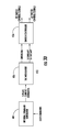
- FIG. 3D is a simplified diagram illustrating a controller for the arrangements of FIGS. 1A, 1B, and 2 ;
- FIG. 4A is a simplified diagram in block and schematic form of a power converter according to an aspect of the disclosure, where the power converter includes hardware portions corresponding to those of FIGS. 1A, 1B , and 2 , and a controller corresponding to FIG. 3D
- FIG. 4B is a simplified logic or command flow chart or diagram illustrating operation of a primary-secondary-tertiary selector of the controller of FIG. 4A
- FIG. 4C is a simplified logic or command flow chart or diagram illustrating operation of a switch control signal generator of FIG. 4A
- FIG. 4D is a time line for aiding in the explanation of the switching control times
- FIG. 4A is a simplified diagram in block and schematic form of a power converter according to an aspect of the disclosure, where the power converter includes hardware portions corresponding to those of FIGS. 1A, 1B , and 2 , and a controller corresponding to FIG. 3D
- FIG. 4B is a simplified logic or command flow chart or diagram illustrating operation of a primary-secondary-
- FIG. 4E is a simplified logic or command flow chart or diagram illustrating operation of a central link current direction determination of a switch-control-signal generator of FIG. 4A
- FIG. 4F is a simplified logic or control flow diagram or chart illustrating the logic associated with calculation of secondary-to-tertiary phase transition time
- FIG. 4G is a simplified logic or control flow diagram or chart illustrating logic steps involved in calculating the required percentage of inversion out of a resonant period
- FIG. 4H is a simplified logic or control flow diagram or chart illustrating the logic for determining the current polarity in the switches
- FIG. 4I illustrates plots of primary, secondary and tertiary current in the arrangement of FIG. 4A ;
- FIG. 5 is a diagram in block and schematic form, similar to FIG. 4A , showing details of the internal command generator for the power converter for use in a DC-to-AC-current-source-mode situation;
- FIG. 6 is a diagram in block and schematic form, similar to FIG. 4A , showing details of the internal command generator for the power converter for use in a DC-to-AC-voltage-source-mode situation;
- FIG. 7 is a diagram in block and schematic form, similar to FIG. 4A , showing details of the internal command generator for the power converter for use in a AC-to-DC situation;
- FIG. 8A is a simplified logic or control flow chart or diagram illustrating overall operation of the arrangement of FIG. 4A
- FIG. 8B includes logic or control flow charts or diagrams illustrating operation of the Mode-Specific User-Command generator of arrangement of FIG. 4A ;
- FIG. 9 represents plots of voltage and current across and through, respectively, the central link capacitor during four consecutive pulses of operation.
- FIG. 1A is a simplified diagram in block and schematic form illustrating a power converter 10 according to an aspect of the disclosure, including a hardware switching “Transverse Alternating Current” (TAC) circuit 12 and a controller 410 .
- the hardware switching circuit 12 couples power by way of an Alternating Current (AC) central link 26 extending between a direct voltage port 16 and a three-phase alternating port 42 coupled to a power grid 44 .
- a direct voltage source 14 at the left of FIG. 1A is illustrated as including a battery 14 b and a voltage sensor 14 s .
- Direct voltage source 14 is coupled to port 16 at terminals, nodes or connections 16 1 and 16 2 .
- Port 16 is also connected to a switching noise reduction low-pass filter 18 .
- Low-pass filter 18 includes a capacitor 18 c coupled across source terminals 16 1 and 16 2 of port 16 .
- Filter 18 also includes “commutation” inductors 18 L1 and 18 L2 , each with one end connected to a terminal 16 1 , 16 2 , respectively.
- the other ends of inductors 18 L1 and 18 L2 are connected at terminals 20 1 and 20 2 to subsets 22 1 and 22 2 , respectively, of set or superset 22 of controllable switches. Details of controllable switch set 22 and controllable switch set or superset 30 , described further on, are illustrated in FIGS. 3B and 3C , respectively.
- Subset 22 1 of controllable switch set 22 is connected between terminal 20 1 and terminals 24 1 and 24 2 of terminals set 24
- subset 22 2 of controllable switch set 22 is connected between terminal 20 2 and terminals 24 1 and 24 2
- Terminals 24 1 and 24 2 of terminals set 24 define first ends of a two-conductor path 25
- terminals 28 1 and 28 2 of terminals set 28 defines the other end of two-conductor path 25
- a series-resonant AC link or “tank” 26 is coupled to two-conductor path 25 .
- the term “tank” is most often used to describe parallel-resonant LC circuits, but is equally applicable to series-resonant circuits with low series resistance.
- the series-resonant link 26 includes a capacitor 26 c and an inductor 26 L.
- series-resonant link 26 can be coupled or connected as illustrated between terminals 24 1 and 28 1 , or can be coupled between terminals 24 2 and 28 2 , or can be allocated with capacitor 26 c connected between terminals 24 1 and 28 1 and with inductor 26 L connected between terminals 24 2 and 28 2 .
- Low-pass filter 18 as a whole, or the inductors 18 L 1 and 18 L 2 may be viewed as being a part of the controllable switch set 22 (also referred to as TAC DC bridge).
- a differential amplifier 26 a has its input ports coupled across capacitor 26 c of tank 26 , and produces a sample of the tank voltage on path 455 .
- the terms “between,” “across,” and other terms such as “parallel” have meanings in an electrical context which differ from their meanings in the field of mechanics or in ordinary parlance. More particularly, the term “between” in the context of signal or electrical flow relating to two separate devices, apparatuses or entities does not relate to physical location, but instead refers to the identities of the source and destination of the flow. Thus, flow of signal “between” A and B refers to source and destination, and the flow itself may be by way of a path which is nowhere physically located between the locations of A and B.
- between can also define the end points of the electrical field extending “across” or to points of differing voltage or potential, and the electrical conductors making the connection need not necessarily lie physically between the terminals of the source.
- parallel in an electrical context can mean, for digital signals, the simultaneous generation on separate signal or conductive paths of plural individual signals, which taken together constitute the entire signal.
- parallel means that the flow of a current is divided to flow in a plurality of separated conductors, all of which are physically connected together at disparate, spatially separated locations, so that the current travels from one such location to the other by plural paths, which need not be physically parallel.
- Coupled includes electrical activity extending from one element to another element either by way of an intermediary electrical element or in the absence of any intermediary electrical element.
- a set or superset 30 of controllable switch sets includes controllable switch subsets 30 1 , 30 2 , and 30 3 .
- Superset 30 is also referred to as TAC AC bridge.
- Switch subset 30 1 of superset 30 connects terminals, nodes or connections 28 1 and 28 2 to a terminal, node or connection 32 1 of a set 32 of terminals, nodes or connections.
- switch subset 30 2 connects terminals 28 1 and 28 2 to a terminal 32 2
- switch subset 30 3 connects terminals 28 1 and 28 2 to a terminal 32 3 .
- Terminals 32 1 , 32 2 , and 32 3 connect to a set 33 of three series “commutation” inductors 33 L 1 , 33 L 2 , and 33 L 3 , respectively, which tend to damp fast current transitions attributable to the commutation of the switches of superset 30 during secondary-to-tertiary switching transition.
- Low-pass filter 34 1 includes a “shunt” capacitor 34 1C connected to conductor or terminal 35 1 and to a neutral conductor 35 4 together with a “series” inductor 34 1 L connected from terminal 35 1 to terminal 36 1 .
- low-pass filter 34 2 includes a shunt capacitor 34 2C connected to terminal 35 2 and to neutral conductor 35 4 together with a series inductor 34 2 L connected from terminal 35 2 to terminal 36 2 .
- Low-pass filter 34 3 includes a shunt capacitor 34 3C connected to terminal 35 3 and to neutral conductor 35 4 together with a series inductor 34 3 L connected from terminal 35 3 to terminal 36 3 .
- three-phase low-pass ell filter 34 connects between the three-phase conductors or terminals of set 35 and the three-phase terminals of set 36 .
- a voltage is generated by three-phase low-pass ell filter 34 during operation of the switched power converter, and a sample of the voltage is made available by a bus or path v34.
- three-phase “filter output” terminals 36 1 , 36 2 , and 36 3 of set 36 of filter terminals are coupled by way of current sensors 38 a , 38 b , and 38 c to three-phase power phases Grid_a, Grid_b, and Grid_c, at terminals 42 1 , 42 2 , and 42 3 , respectively, of AC port 42 .
- the three-phase AC or grid terminals are designated together as 42 .
- a set 40 of voltage sensors is coupled to the Grid_a, Grid_b, and Grid_c phases of the grid.
- the grid itself is designated 44 .
- the power grid may be viewed as being a “voltage” or low-impedance source, the voltage of which cannot be changed by applying voltage from an external source. That is to say, the grid 44 may be viewed as having zero internal impedance.
- FIG. 1A can be operated or controlled in a bidirectional manner, depending upon how the switches are controlled. That is to say, that power may flow from the direct voltage source 14 to the alternating grid 44 at port 42 (that is, from left to right in FIG. 1A ), or may flow from the alternating grid 44 at port 42 to the direct voltage source 14 (from right to left in FIG. 1A ).
- the direct-voltage source battery 14 b conceptually discharges when power flows therefrom to the grid 44 , and the battery 14 b charges when power flows from the grid 44 to the battery.
- the voltage of the grid cannot be varied, so flow of power to and from the grid at three-phase port 42 is accomplished by application of current.
- the battery or direct voltage source 14 is ideal, it has no internal impedance, so the same current mode operation is required for transfer of power to the direct voltage source 14 at port 16 .
- FIG. 1A shows a battery 14 connected to DC port 16
- a direct-voltage load such as a resistor
- FIG. 1B illustrates a resistive load 13 connected to direct-voltage terminals 16 1 and 16 2 of port 16 instead of a battery.
- FIG. 2 is a simplified diagram in block and schematic form, illustrating another aspect of the disclosure.
- elements corresponding to those of FIG. 1A are designated by like reference alphanumerics.
- the salient difference between the arrangements of FIG. 1A and FIG. 2 is that the alternating power port 42 of FIG. 1A is connected to a voltage source (grid 44 ) while the alternating power or alternating current port 42 of FIG. 2 is connected to a three-phase resistive load designated generally as 244 .
- the significance of this difference is that the voltage across the three-phase port 42 can be controlled in the arrangement of FIG. 2 , while it cannot be controlled in the arrangement of FIG. 1A .
- a resistive load is illustrated, those skilled in the art recognize that an inductive or capacitive load may also be used.
- FIG. 3A is a simplified representation showing some details of the switching circuit sets or supersets 22 and 30 of FIGS. 1A and 2 .
- elements corresponding to those of FIG. 1A or 2 are designated by like reference alphanumerics.
- Details of Transverse Alternating Current (TAC) DC bridge or switch superset 22 and of TAC AC bridge or switch superset 30 of FIG. 3A appear in FIGS. 3B and 3C , respectively.
- switch superset 22 includes switch subsets 22 1 and 22 2 , each of which includes a plurality of Gate-Turn-Off (GTO) thyristors (GTOs) and antiparallel diodes or rectifiers.
- GTO Gate-Turn-Off
- GTOs Gate-Turn-Off
- DC bridge switch subset 22 1 includes four GTO switches
- DC bridge switch subset 22 2 includes four GTO switches.
- a first GTO switch 322 1S1 is controlled by signals applied to a gate lead 322 1S1c , and is antiparalleled by a diode or rectifier 322 1D1 .
- a second GTO switch 322 1D2 is controlled by signals applied to a gate lead 322 1S2c and is antiparalleled by a diode or rectifier 322 1D2 .
- the cathode of GTO switch 322 1S1 is connected to terminal 20 1 and the anode is connected to the anode of GTO switch 322 1S2 .
- the cathode of GTO switch 322 1S2 is connected to terminal 24 1 .
- a third GTO switch 322 1S3 is controlled by signals applied to a gate lead 322 1S3c , and is antiparalleled by a diode or rectifier 322 1D3 .
- a fourth GTO switch 322 1S4 is controlled by signals applied to a gate lead 322 1S4c and is antiparalleled by a diode or rectifier 322 1D4 .
- the cathode of GTO switch 322 1S3 is connected to terminal 20 1 and the anode is connected to the anode of GTO switch 322 1S4 .
- the cathode of GTO switch 322 1S4 is connected to terminal 24 2 .
- a first GTO switch 322 2S1 is controlled by signals applied to a gate lead 322 2S1c , and is antiparalleled by a diode or rectifier 322 2D1 .
- a second GTO switch 322 2S2 is controlled by signals applied to a gate lead 322 2S2c and is antiparalleled by a diode or rectifier 322 2D2 .
- the cathode of GTO switch 322 2S1 is connected to terminal 20 2 and the anode is connected to the anode of GTO switch 322 2S2 .
- the cathode of GTO switch 322 2S2 is connected to terminal 24 1 .
- a third GTO switch 322 2S3 is controlled by signals applied to a gate lead 322 2S3c , and is antiparalleled by a diode or rectifier 322 2D3 .
- a fourth GTO switch 322 2S4 is controlled by signals applied to a gate lead 322 2S4c and is antiparalleled by a diode or rectifier 322 2D4 .
- the cathode of GTO switch 322 2S3 is connected to terminal 20 2 and the anode is connected to the anode of GTO switch 322 2S4 .
- the cathode of GTO switch 322 2S3 is connected to terminal 24 2 .
- the configuration of GTO switches of FIG. 3B allows control of the current flowing between the central tank or resonant circuit 26 and the single-phase terminals of set 20 .
- AC Bridge switch superset 30 includes switch subsets 30 1 , 30 2 , and 30 3 , each of which includes a plurality of Gate-Turn-Off (GTO) thyristors (GTOs) and antiparallel diodes or rectifiers.
- Switch superset 30 includes switch subsets 30 1 , 30 2 , and 30 3 , each of which subsets includes a plurality of Gate-Turn-Off (GTO) thyristors (GTOs) and antiparallel diodes or rectifiers. The operation of such GTO switches is well known.
- GTO Gate-Turn-Off
- AC bridge switch subset 30 1 includes four GTO switches
- AC bridge switch subset 30 2 includes four GTO switches
- AC bridge switch subset 30 3 includes four GTO switches.
- a first GTO switch 330 1S1 is controlled by signals applied to a gate lead 330 1S1c , and is antiparalleled by a diode or rectifier 330 1D1 .
- a second GTO switch 330 1S2 is controlled by signals applied to a gate lead 330 1S2c and is antiparalleled by a diode or rectifier 330 1D2 .
- the cathode of GTO switch 330 1S1 is connected to terminal 28 1 and the anode is connected to the anode of GTO switch 330 1S2 .
- the cathode of GTO switch 330 1S2 is connected to terminal 32 1 .
- a third GTO switch 330 1S3 is controlled by signals applied to a gate lead 330 1S3c , and is antiparalleled by a diode or rectifier 330 1D3 .
- a fourth GTO switch 330 1S4 is controlled by signals applied to a gate lead 330 1S4c and is antiparalleled by a diode or rectifier 330 1D4 .
- the cathode of GTO switch 330 1S3 is connected to terminal 28 2 and the anode is connected to the anode of GTO switch 330 1S4 .
- the cathode of GTO switch 330 1S4 is connected to terminal 32 1 .
- a first GTO switch 330 2S1 is controlled by signals applied to a gate lead 330 2S1c , and is antiparalleled by a diode or rectifier 330 2D1 .
- a second GTO switch 330 2S2 is controlled by signals applied to a gate lead 330 2S2c and is antiparalleled by a diode or rectifier 330 2D2 .
- the cathode of GTO switch 330 2S1 is connected to terminal 28 1 and the anode is connected to the anode of GTO switch 330 2S2 .
- the cathode of GTO switch 330 2S2 is connected to terminal 32 2 .
- a third GTO switch 330 2S3 is controlled by signals applied to a gate lead 330 2S3c , and is antiparalleled by a diode or rectifier 330 2D3 .
- a fourth GTO switch 330 2S4 is controlled by signals applied to a gate lead 330 2S4c and is antiparalleled by a diode or rectifier 330 2D4 .
- the cathode of GTO switch 330 2S3 is connected to terminal 28 2 and the anode is connected to the anode of GTO switch 330 2S4 .
- the cathode of GTO switch 330 2S4 is connected to terminal 32 2 .
- a first GTO switch 330 3S1 is controlled by signals applied to a gate lead 330 3S1c , and is antiparalleled by a diode or rectifier 330 3D1 .
- a second GTO switch 330 3S2 is controlled by signals applied to a gate lead 330 3S2c and is antiparalleled by a diode or rectifier 330 3D2 .
- the cathode of GTO switch 330 3S1 is connected to terminal 28 1 and the anode is connected to the anode of GTO switch 330 3S2 .
- the cathode of GTO switch 330 3S2 is connected to terminal 32 3 .
- a third GTO switch 330 3S3 is controlled by signals applied to a gate lead 330 3S3c , and is antiparalleled by a diode or rectifier 330 3D3 .
- a fourth GTO switch 330 3S4 is controlled by signals applied to a gate lead 330 2S4 , and is antiparalleled by a diode or rectifier 330 3D4 .
- the cathode of GTO switch 330 3S3 is connected to terminal 28 2 and the anode is connected to the anode of GTO switch 330 3S4 .
- the cathode of GTO switch 330 3S4 is connected to terminal 32 3 .
- the configuration of GTO switches of FIG. 3C allows control of the current flowing between the central tank or resonant circuit 26 and the three-phase terminals of set 32 .
- FIG. 3D is a simplified representation of the controller 410 ( FIGS. 1A and 2 ) for controlling the transverse AC (TAC) DC bridge 20 of FIG. 3B and the TAC AC bridge 30 of FIG. 3C .
- user commands e.g. requested power, desired DC voltage and etc.
- Internal command generator 401 produces 3-phase current command signals, which determines what the currents should “look like” at the terminals of AC port 42 to satisfy the user commands.
- the 3-phase current command signals are applied to a TAC modulator 416 .
- TAC modulator 416 calculates or produces inversion and secondary-to-tertiary ratio or duty cycle (time percentage) signals which are required to satisfy the current commands.
- the inversion and secondary-to-tertiary ratio or duty cycle (time percentage) signals are applied to a switch controller or switch control-signals generator 456 .
- the switch control-signals generator 456 selects the active switches using the sensor readings, feedbacks, and current commands. Switch ON and OFF times are calculated to produce DC and AC bridge switch control signals.
- the power converter 10 can be operated in any one of three separate modes.
- the operations of the TAC modulator 416 and of the switch control-signals generator 456 are not mode-dependent, and have the same sequence for all the three modes of operation.
- Internal command generator 401 has a mode specific operation sequence.
- FIG. 4A is a simplified diagram in block and schematic form illustrating the arrangements of FIG. 1A, 1B , or 2 together with some details of the controller 410 of FIG. 3D . Elements of FIG. 4A corresponding to those of FIGS. 1A, 1B, 2, and 3D are designated by like alphanumerics.
- the controller 410 controls power conversion in any one of (a) DC-to-AC-voltage-source operating mode (AC port 42 has a resistive load), (b) DC-to-AC-current-source operating mode (AC port is connected to power grid at the AC port 42 ), and (c) AC-to-DC operating mode (grid provides power to the DC port and regulates the DC port voltage).
- the DC-to-AC-voltage-source operating mode assumes that the AC terminals or port 42 are/is connected to a load, so that the voltage across the AC port can be varied to effectuate a power transfer.
- the DC-to-AC-current-source operating mode assumes that the power grid is connected to the AC terminals or port, and the voltage of the grid cannot be varied, so power application to the AC terminals is by way of application of current and not of voltage.
- the AC-to-DC operating mode assumes that power flows from the AC port or terminals to the DC terminals or port, which may be coupled to either a source as in FIG. 1A or a resistor as in FIG. 1B .
- the arrangement of FIG. 4A includes the controller 410 and user controller 412 .
- FIG. 8A is a simplified logic or control flow chart or diagram illustrating major steps in the overall operation of the controller 410 of FIG. 4A in controlling the power converter 10 of FIG. 1A, 1B or 2 in all operating modes.
- the logic starts at a BEGIN block 800 , and flows to a block 801 .
- Logic block 801 represents the receipt by the controller 410 of the user commands from an external source, or alternatively the reception of user commands at block 412 .
- the logic flows to a block 802 .
- Block 802 represents the receipt of the various feedback signals, such as the DC voltage on capacitor 18 c , the voltage of central tank 26 , the voltage of filter 34 , the voltage and current at AC port 42 .
- Block 803 represents the generation by the internal command generator 401 of FIG. 4A , (or the internal command generators 501 ( FIG. 5 ) 601 ( FIG. 6 or ⁇ 701 ( FIG. 7 ), of the internal commands appropriate to the mode of operation, or in other words block 803 represents the generation of the internal command, namely the desired AC currents at port 42 .
- Block 804 of FIG. 8A represents the determination or calculation of the switch time instants in the TAC Modulator 416 , including selection of the active switches.
- Block 805 represents the finding of the active switches or finding the switch gate control. The logic terminates at an END block 806 .
- user controller 412 includes an operating mode selector 413 , which receives the desired operation mode from the user.
- the selected mode of operation is made available to a Mode-specific user-command selector 415 , which chooses the appropriate set of operation commands according to the logic or command flowchart in FIG. 8B from the possible set 417 of operation commands 417 .
- a user command is applied to user controller 412 commanding the loading of the parameters applicable to the desired operating mode. More particularly, for the DC-to-AC-voltage-source (load connected to AC port 42 ) operating mode, only the AC peak voltage setpoints are required. For the DC-to-AC-current-source operating mode (grid connected to the AC port 42 ), the grid real and reactive power references are required.
- the direct voltage setpoint is required, and the grid reactive power is also required, but may be defaulted to zero (unity power factor). These values are preprogrammed based on the capabilities of the circuit or hardware 12 .
- the values of the selected parameters are made available from selector 415 to the internal command generator 401 .
- the internal command generator 401 receives samples of the direct voltage at the direct voltage port 14 by way of a sample path 454 , and also receives, by way of sample buses or paths 450 and 452 , samples of the grid AC current and grid AC voltage at port 42 .
- the internal command generator 401 of FIG. 4A generates on a bus 418 , in all three modes of operation, 3-phase current command signals representative of the current which is to flow in AC port 42 .
- FIG. 8B is a simplified logic flow chart 830 illustrating operation of the internal command generator 401 and the user controller 412 of FIG. 4A .
- the logic starts at a BEGIN block 832 , and flows to a decision block 834 , which determines the commanded mode of operation, with the possibilities being AC-to-DC, DC-to-AC in the voltage source mode, and DC-to-AC in the current-mode mode. If the AC-to-DC mode has been selected, the logic leaves decision block 834 by the AC/DC path 835 and flows to a block 836 .
- Block 836 represents calculation of the amount of real current (Id) at port 42 required to regulate the DC bus voltage at port 14 .
- Block 838 represents the calculation of the reactive current (Iq) required to maintain unity power factor (by default, or any other commanded phase angle/reactive power if the reactive power command value is set by the user) at port 42 .
- decision block 834 determines that the mode of operation is to be DC-to-AC in the voltage source mode
- the logic leaves decision block 834 by the DC/AC voltage source mode path 839 , and flows to a block 840 .
- Block 840 represents the calculation of the amount of real current (Id) required to regulate the AC voltage at AC port 42 .
- Block 842 represents the setting to zero of the Iq setpoint (since Iq will be determined from the load characteristics and cannot be controlled independently from Id).
- Block 846 represents the calculation of the real current Id required to follow the real power command.
- Block 848 represents the calculation of the amount of reactive current Iq required to follow/satisfy the user the reactive power command. From any one of blocks 838 , 842 , or 848 , the logic 830 flows to an END block 850 .
- the three-phase current command signals on bus 418 of the controller 410 of FIG. 4A are applied to a NORM2 ( ⁇ square root over (i a 2 +i b 2 +i c 2 ) ⁇ ) function block 420 and to a primary-secondary ratio calculator 422 .
- NORM2 function block or norm calculator 420 and the primary-secondary ratio calculator 422 are both found in the Transverse AC (TAC) modulator 416 .
- TAC Transverse AC
- the primary-secondary ratio calculator 422 calculates the desired (set point) value or ratio of the secondary current to the primary current.
- “primary” current is the current of the primary phase and secondary current is the current of the secondary phase, which are selected by a primary-secondary-tertiary phase selector 428 .
- the command NORM 2 (cmd norm) signal from NORM2 function block 420 is applied to a subtracting circuit 430 , which also receives, by way of a path 429 , a maximum possible command norm signal, representing the normalized nominal AC current.
- the output of subtracting circuit 430 represents the percentage of “inversion” time for the next following pulse. This percentage-of-inversion-time signal is applied to switch control-signals generator 456 , which calculates the GTO switch control signals for DC switch superset 22 .
- 4G is a simplified flow chart illustrating the overall operation of NORM2 function block 420 , path 429 , and subtracting circuit 430 .
- the “inversion” percentage is a measure of the required limitation of the power throughput. For example, if the circuit is capable of producing 1 unit of nominal power and the user is requesting only 0.5 unit power, the power throughput has to be limited somehow to satisfy the user commands. This is accomplished by means of “inversion” (i.e. not passing any power by forming a short in the input port for a percentage of time during each pulse).
- the Primary-secondary-tertiary phase selector 428 of FIG. 4A generates signals representing or identifying the three phases of the alternating port 42 .
- the phase order signals are identified to ratio secondary/primary ratio calculators 422 and 426 , and the switch control-signals generator 456 .
- the ratio calculator 426 receives the phase order information from phase selector 428 and the three-phase grid (or load) current feedback by way of bus 450 .
- the ratio calculator 426 performs the same function as the ratio calculator 422 on the actual (feedback) currents from port 42 , to produce an actual current ratio as feedback to a proportional-integral processor (PI) 424 , which processes the ratio set-point and the ratio feedback to produce secondary-to-tertiary time percentage adjustment.
- PI proportional-integral processor
- the three-phase current command signals on bus 418 are applied to ratio calculator 422 , and are processed in ratio calculator 422 together with signals representing the order of the three phases from block 428 , to produce a ratio set-point or desired set-point.
- the ratio set-point from ratio calculator 422 is applied to PI processor 424 .
- PI block 424 also receives actual ratio feedback from ratio calculator 426 .
- the ideal secondary-to-tertiary time percentage signal is equal to the ratio setpoint.
- the ideal value of, and the correction to, the secondary-to-tertiary time percentage are added together in an adder 432 to produce the secondary-to-tertiary time percentage as an input to the switch control-signals generator 456 to produce the secondary-to-tertiary time percentage command which represents the time instant in the next occurring pulse at which the transition between the secondary phase to tertiary phase will occur.
- the flow chart of FIG. 4F sets forth the logic performed by ratio calculator 422 , PI processor 424 , ratio calculator 426 , and adder 432 of FIG. 4A .
- the logic 488 starts at a BEGIN block 488 1 , and flows to a block 488 2 .
- Block 488 2 represents reception of the three-phase current commands from the internal command generator 401 .
- Block 488 3 represents the reception of three-phase current feedback and voltage feedback.
- Block 488 4 represents the calculation of ideal secondary-to-tertiary transition time (Ds2t_ideal).
- Block 488 5 represents calculation of the percentage adjustment (the secondary-to-tertiary ratio correction) or Ds2t_correction.
- the logic of FIG. 4F ends at a block 488 7 .
- FIG. 4G illustrates the logic 489 for determining the percentage of inversion time, as performed by the NORM2 function block 420 , the path 429 , the subtracting circuit 430 , and the adder 432 of FIG. 4A .
- the logic 489 starts at a BEGIN block 489 1 , and flows to a block 489 2 .
- Logic block 489 2 represents reception of the 3-phase current commands from Internal Command Generator 401 of FIG. 4A .
- Block 489 3 represents calculation of the peak value (norm) of the commands (Icmd_peak).
- Logic 489 of FIG. 4G ends at an END block 489 5 .
- FIG. 4B is a simplified flow chart illustrating the logic flow in phase identifier or primary-secondary-tertiary Selector (PST order) 428 of FIG. 4A .
- the logic begins at a BEGIN block 434 and flows to a block 436 .
- Block 436 represents receipt of sensor values representing the AC currents at port 42 and the AC filter capacitor 34 voltages.
- the logic of FIG. 4B flows to a block 438 , representing determination of the phase having the maximum absolute magnitude of instantaneous current, and deeming this phase to be the “primary” phase.
- Decision block 440 decides if the AC port is the input port or the output port, thereby allowing selection of the secondary and tertiary phases depending upon their voltages relative to the primary phase. If the AC port is the output port, the logic leaves decision block 440 by the NO output, and flows to a block 442 .
- Block 442 selects the secondary and tertiary phases such that the voltage difference between primary and secondary phase should be smaller than the voltage difference between tertiary and primary.
- V Pri ⁇ V Ter
- Block 444 selects the secondary and tertiary phases such that the voltage difference between primary and secondary phase is larger than the voltage difference between tertiary and primary.
- FIG. 4C illustrates the logic 448 performed in switch-control-signal generator 456 of FIG. 4A .
- the logic begins at a BEGIN block 448 1 , and flows to a block 448 2 .
- Block 448 2 represents reception of the primary, secondary, and tertiary phase order or identifications (pst order), and of the inversion percentage command (Dinv) and secondary-to-tertiary percentage command (Ds2t) signals.
- the logic 448 flows to a block 448 3 .
- Block 448 3 represents the calculation of the switching times or instances.
- Block 448 4 of FIG. 4C represents the determination of the current direction in the central link 26 . Details of block 448 4 are illustrated in conjunction with FIG.
- Block 448 5 of FIG. 4C represents determination of the polarity of the switches in the input and output bridges or ports. Details of block 448 5 are described in conjunction with FIG. 4H .
- the active switches are determined in block 448 6 of FIG. 4C .
- Block 448 7 represents the generation of the ON/OFF control signals for the control electrodes of the DC and AC switch sets. The logic of FIG. 4C terminates at an END block 448 8 .
- FIG. 4D is a simplified time line illustrating salient times in the operation of the calculation in block 448 3 of logic 448 of FIG. 4C .
- the starting time of the next occurring pulse or time 0 is designated t(start).
- the system starts in the inversion mode rather than in the normal mode.
- the input port In the inversion mode, the input port is shorted, and no power flows to the central link or tank 26 from the input port in order to control (reduce) the power throughput.
- the input port goes back to normal (non-shorted) operation to pass the power to the output port through the central link.
- Dinv is the inversion percentage.
- the inversion percentage is multiplied by the resonant period Tr (in seconds) to produce Dinv ⁇ Tr. That is, the inversion to normal transition happens at a time t(inv) calculated by adding the inversion period duration or length to the start time t(start). Inversion period is calculated by multiplying the inversion percentage Dinv by the resonant period length Tr (in seconds) to generate the inversion period shown by “Dinv ⁇ Tr” in FIG. 4D . The inversion mode of operation ceases, and operation in the normal mode begins, at time t(inv) of FIG. 4D .
- the required period is calculated by multiplying the secondary-to-tertiary percentage Ds2t by resonant period Tr to find the time instant t(s2t) as a product, and adding the product to the start time t(start).
- the secondary phase will gradually stop feeding the primary phase and the tertiary phase will continue feeding the primary instead of the secondary phase.
- the gradual transition is because of the presence of the commutation inductors (inductors of sets 18 or 34 ).
- Time Tsw represents the switching period.
- the pulse length, in seconds, is shown by “L ⁇ Tr” in FIG. 4D , where L is a constant which is set at a value slightly larger than the maximum inversion required in each power-level plus one “1+max(Dinv)”, to make sure no hard-switching event can occur.
- L is a constant which is set at a value slightly larger than the maximum inversion required in each power-level plus one “1+max(Dinv)”, to make sure no hard-switching event can occur.
- Tsw the required switching period
- logic 448 flows to a block 448 1 , which represents determination of the current flow direction in central link 26 of FIG. 1A, 1B or 2 .
- the logic starts at a BEGIN block 462 , and flows to a block 464 , which represents receipt of voltage feedback from the central link 26 voltage sensor 26 A.
- logic 461 flows to a decision block 466 , which determines whether the central link voltage is positive. If the central link voltage is not positive, the logic leaves decision block 466 by the NO output, and arrives at a block 468 .
- Block 468 represents the determination that the current flow is clockwise (CW).
- the logic leaves decision block 466 by the YES output and arrives at a block 470 , representing a determination that the current flow in the central link is counterclockwise (CCW).
- Logic 461 of FIG. 4E ends at END block 472 , and the logic returns to block 448 5 of FIG. 4C .
- block 448 5 of FIG. 4C represents determination of the positive or negative polarities of the input and output currents.
- FIG. 4H is a simplified logic flow chart or diagram illustrating the logic 473 of block 448 5 of FIG. 4C .
- the DC port polarity is set to positive either when there is a load (such as resistor 13 of FIG. 1B ) connected to the DC capacitor 18 c or when a battery is connected and it is being charged.
- the DC polarity is set to negative if the battery is being discharged.
- AC port polarity is determined by the polarity of the primary current, the polarity is deemed to be positive if the primary current is positive and negative otherwise.
- the polarities of the input and output currents are defined as: for the output (AC or DC) port, positive direction is the direction of exiting the switches and for the input port (DC or AC) it is the direction of entering the switches.
- the logic 473 of FIG. 4H starts at a BEGIN block 474 , and flows to a block 476 , representing the reception of the current feedback signals. From block 476 , logic 473 flows to a decision block 478 . Decision block 478 decides whether the polarity is being calculated for the input port or for the output port. If it is for the output port, the logic leaves decision block 478 by the NO path, and if it is for the input port, the logic leaves block 478 by the YES path.
- decision block 480 determines if current flows out of the switch in question. If current flows out of the switch, the logic leaves decision block 480 by the YES path and flows to a block 486 , representing the setting or determination of the polarity as being positive (p). If current flows into the switch, the logic leaves decision block 480 by the NO path and flows to a block 484 , representing the setting or determination of the polarity as being negative (n).
- the YES output path of decision block 478 leads to a further decision block 482 . Decision block 482 determines if current flows into the switch in question.
- logic 473 ends at an END block 487 , and returns to block 448 5 of FIG. 4C .
- each switch can be described by the triplet [ I direction ,I polarity , phase order] where:
- each switching pulse can be divided into three separate switching portions for the input (AC) port:
- each switching pulse can be divided into two separate switching portions for the input (DC) port and into two separate switching portions for the output (AC) port.
- the DC (input) port operation separates the pulse into two portions around the inversion transition time t(inv) and the AC (output) port operation separates the pulse into two portions around the secondary to tertiary transition time t(s2t).
- DC port enters the inversion mode by activating two switches with different polarities from among the switches of the primary DC switch set: [I direction , I dc polarity , DC Primary] and [I direction , I dc polarity , DC primary] to block the current from the DC input port.
- the secondary phase DC switch [I direction , I dc polarity , DC secondary] becomes active for letting the current flow from the input port to the central link through this secondary phase switch and the primary switch [I direction , I dc polarity , DC Primary] which was activated at the beginning of the first portion of the pulse.
- the primary phase is the phase which has the largest absolute value of current
- the secondary and tertiary phases are selected based on the AC voltages, satisfying, in the case of the AC port being the output port
- Block 448 6 represents the identification of the active switches.
- the identification of the active switches is explained with reference to FIG. 4I .
- the primary, secondary and tertiary phases are designated as such.
- FIG. 4I represents the 3-phase AC currents flows through the primary, secondary and tertiary phases over a single switching period, assuming that the inverter is operating in the DC/AC operation modes, and hence the inversion sequence occurs at the DC (input) port.
- the central link's current has the exact same shape as the primary current in this case, but out-of-phase every other pulse. Note that at time t(s2t) the secondary current starts to be gradually replaced by the tertiary current.
- tertiary and primary phase switches are active in the AC input port.
- the DC port operates in normal condition for the whole duration of the pulse since it is in the output port.
- DC active switches are selected to satisfy the polarity and current direction as explained above.
- DC-to-AC (DC/AC) operating mode either voltage or current source
- the DC port starts operating by activating two different switches from the DC primary switch set (one with positive and the other one with negative polarity), and with no switch from the secondary switch set. By switching in this way, a short circuit is produced or performed in the input (DC) port, which prevents the flow of power from the DC source to the central link.
- Normal sequence starts after the inversion transition time t(inv) is reached, and at that time the secondary DC phase starts feeding the primary DC phase.
- the AC port operates in normal condition for the whole duration of the pulse since it is in the output port.
- AC active switches are selected to satisfy the polarity and current direction, as explained above.
- the ON/OFF control signals for DC and AC switch sets are determined in block 448 7 , thereby satisfying the active switch selections and the switch timing instances.
- the logic 448 ends at an END block 448 8 .
- FIGS. 5, 6, and 7 illustrate details of the internal command generator 401 of FIG. 4A for the DC-to-AC current mode, the DC-to-AC voltage mode, and the AC-to-DC operating modes, respectively. Since the makeup of the internal command generators differ from one to the other depending upon the application to which the power converter 10 is put, the designations of the internal command generators differ in FIGS. 5, 6, and 7 . More particularly, the internal command generator of FIG. 5 is designated 501 , the internal command generator of FIG. 6 is designated 601 , and the internal command generator of FIG. 7 is designated 701 .
- FIG. 5 illustrates details of the internal command generator 401 (of FIG. 4A ) for the case of operation of the power converter 10 for DC-to-AC-grid current source mode of operation (that is, with the three-phase grid 44 applied to the AC terminals 42 ).
- the internal command generator of FIG. 5 is designated 501 .
- the DC-to-AC-current-mode of operation power can only be transferred to the grid by driving it with current, as the internal impedance of the grid is nominally zero.
- elements corresponding to those of FIG. 4A are designated by like reference alphanumerics.
- FIG. 5 elements corresponding to those of FIG. 4A are designated by like reference alphanumerics.
- block 412 produces the grid real and reactive power references or setpoints.
- the real and reactive power references are applied from block 412 to division circuits 512 and 514 , respectively, of internal command generator 501 .
- Division circuits 512 and 514 also receive nominal power reference signals.
- Division circuits 512 and 514 divide the user commanded real and reactive power by the nominal power to normalize the commanded signals and to thereby generate the real (grid Id) and reactive (grid Iq) current setpoints.
- the real current setpoint (Grid I d setpoint) is applied to a PI block 516
- the reactive current setpoint (grid Iq) is applied to a PI block 518
- real (grid Id fb) and reactive (grid Iq fb) current feedback signals respectively, from block 520
- PI blocks 516 and 518 produce the real and reactive current commands Id cmd and Iq cmd, respectively.
- Block 520 receives the sampled grid currents from sample path 450 and the grid phase angle from a block 524 , and performs the Clarke-Park (abc-to-dq) transform to transform the three-phase grid current to Id and Iq feedback.
- the grid phase A voltage angle is determined by block 524 based on the sampled grid voltages from sample path 452 .
- Transform block 522 receives the grid phase angle and the real and reactive current commands, and performs the reverse Clarke-Park transform (that is, dq-to-abc transform) to generate the three-phase current command signal on path 418 for application to TAC modulator 416 .
- FIG. 6 illustrates details of the internal command generator for the case of operation of the power converter 10 for DC-to-AC-load voltage source mode (that is, with the three-phase load applied to the AC terminals 42 .
- block 412 produces the AC voltage setpoint for application to a PI block 516 of internal command block 601 .
- a NORM2 block 612 receives three-phase AC load voltage reference signals for load phases a, b, and c, and determines the peak AC voltage magnitude by ⁇ square root over (v a 2 +v b 2 +v c 2 ) ⁇ .
- the peak AC-voltage-representative feedback signal is applied from block 612 to proportional-integral (PI) block 516 .
- PI block 516 produces M, the modulation index, for application to a 3-phase current command generator 620 .
- the modulation index represents the magnitude of the three-phase current commands which are applied to TAC modulator block 416 .
- Three-phase current command generator 620 acts on the modulation index M and the desired output phase angle to generate the three-phase current commands for application by way of paths 418 to TAC modulator 416 .
- Block 620 internally generates ⁇ , which is the desired output load voltage angle, which increments from a value of zero (0) at start-up, with the rate of increment 120 ⁇ /f sw where f sw is the switching frequency.
- FIG. 7 illustrates details of the internal command generator 401 (of FIG. 4A ) for the case of operation of the power converter 10 for AC-grid-to-DC operation (that is, with the three-phase grid 44 applied to the AC terminals 42 and a load connected to DC port 14 ).
- the internal command generator of FIG. 7 is designated 701 .
- the grid voltage is fixed, and power is extracted from the grid by controlling the AC current.
- elements corresponding to those of FIG. 4A are designated by like reference alphanumerics.
- FIG. 7 elements corresponding to those of FIG. 4A are designated by like reference alphanumerics.
- block 412 produces the DC voltage setpoint and the grid reactive power reference (which may be set to zero if not otherwise specified).
- the reactive power reference is applied from block 412 to division circuit 512 of internal command generator 701 .
- Division circuit 512 also receives nominal power reference signals.
- Division circuit 512 divides the user commanded reactive power by the nominal power to normalize the commanded signals and to thereby generate the reactive (grid Iq) current setpoints.
- the DC voltage setpoint is applied from block 412 to a PI block 516 , which also receives a sample of the DC voltage.
- the reactive current setpoint (grid Iq) is applied from block 512 to a PI block 518 .
- PI block 518 also receives reactive (grid Iq fb) current feedback signals from block 520 .
- Block 520 receives the sampled grid currents from sample path 450 and the grid phase angle from a block 524 , and performs the Clarke-Park (abc-to-dq) transform to transform the three-phase grid current to Id and Iq feedback signals, but in the AC-to-DC mode of operation only the reactive current Iq is used.
- PI blocks 516 and 518 produce the real and reactive current commands Id cmd and Iq cmd, respectively.
- the grid phase A voltage angle is determined by block 524 based on the sampled grid voltages from sample path 452 .
- Transform block 522 receives the grid phase angle from path 516 and also receives the real (Id cmd) and reactive (Iq cmd) current commands, and performs the reverse Clarke-Park transform (that is, dq-to-abc transform) to generate the three-phase current command signal on path 418 for application to TAC modulator 416 .
- a power converter comprises a DC port, an AC port, a central resonant circuit, and a set of controllable “DC” switches coupled to the DC port and to the central resonant circuit.
- the power converter also comprises a filter coupled to the AC port and a set of “AC” switches coupled to the central resonant circuit and to the filter.
- the filter generates a voltage during operation of the converter.
- a switch control-signals generator is coupled to the DC and AC switches, and is responsive to phase order, to secondary-to-tertiary time percentage, and to inversion time percentages for controlling inversion and normal conduction times of the DC and AC switches.
- a modulator is responsive to the voltage of the filter, to current command signals, and to the current at the AC port, for generating the phase order, inversion time percentage and secondary-to-tertiary time percentage.
- the central resonant circuit may be a series resonant circuit.
- the modulator comprises a primary-secondary-tertiary selector coupled to the filter for determining the phase order, and a norm calculator coupled to receive the current command signals, for generating normalized current command signal.
- a subtractor is coupled to the norm calculator for subtracting the normalized current command signal from signal representing a maximum possible value of the current command signal, to thereby generate the inversion time percentage.
- a secondary-to-primary current ratio calculator is coupled to receive the current command signals, and is also coupled for receiving the phase order, for generating ideal secondary-to-primary ratio.
- a secondary-to-primary current ratio calculator is coupled to receive the phase order, and is also coupled to receive a sample of the current at the AC port, for generating actual secondary-to-primary ratio.
- a proportional-integral processor is coupled for receiving the ideal and actual secondary-to-primary ratios, for generating secondary-to-tertiary percentage adjustment signal, and a summing processor is coupled to receive the actual secondary-to-primary ratio and is also coupled to receive the secondary-to-tertiary percentage adjustment signal, for summing a secondary-to-primary percentage adjustment signal with the ideal secondary-to-primary ratio to thereby produce the secondary-to-primary time percentage.
- the switch control-signals generator responsive to phase order, to secondary-to-tertiary time percentage, and to inversion time percentage for controlling the inversion and normal conduction times of the DC and AC switch supersets comprises (a) a switching time calculator for receiving the secondary-to-tertiary transition time and the inversion time, and for calculating the switching times therefrom, (b) a current direction determining arrangement for finding the central link current direction, (c) a current polarity determining arrangement for determining the input and output current polarities), (d) an active switch finder for finding the active switches, and (e) a signal generator for generating the ON and OFF switch control signals for the active switches.
- a controller for a power converter includes a direct voltage port and a three-phase AC port, and also includes a low-pass filter.
- the low-pass filter includes a low-pass filter first port and a low-pass filter second port, with the low-pass filter second port being coupled to the three-phase port of the converter.
- the low-pass filter also includes a set of filter sample voltage connections coupled for sampling low-pass filter voltages.
- the power converter includes a resonant central link which may be series-resonant.
- the power converter also includes first and second controllable switch sets. The first switch set connects the direct voltage port to the central link, and the second controllable switch set connects the central link to the low-pass filter first port in each of three possible operating modes.
- the power converter also includes alternating voltage and current sensors coupled to the alternating port, for generating samples of the alternating voltage and current, respectively.
- the power converter also includes a direct voltage sensor coupled to the direct voltage port for generating samples of the direct voltage.
- power is transferred from the direct voltage port to the alternating port with controlled real and reactive power.
- power is transferred from the direct voltage port to the three-phase port with constant peak three-phase voltage
- power is transferred from the three-phase port to the direct voltage port.
- the controller comprises a switch element controller for generating ON-OFF control signals for the first and second controllable switch sets in response to inversion and secondary-to-tertiary time percentages.
- a modulator is responsive to the filter voltage and to the current at the AC port, for generating the inversion and secondary-to-tertiary time percentages.
- the resonant circuit is series-resonant.
- a power converter comprises a DC port, an AC port, and a central resonant circuit.
- the central resonant circuit may be a series-resonant circuit.
- the power converter comprises a set of controllable “DC” switches coupled to the DC port and to the central resonant circuit, and a filter coupled to the AC port, which filter generates a voltage during operation of the converter.
- the power converter also comprises a set of “AC” switches coupled to the central resonant circuit ( 26 ) and to the filter.
- An internal command generator calculates the currents required at the AC port to satisfy at least the desired converter power and DC voltage, and generates internal current commands representing the currents at the AC port.
- a switch control circuit is coupled to the DC and AC switches, for selecting the active switches in response to sensor feedback and the internal current commands, and for calculating switch ON and OFF times using “inversion” and “secondary-to-tertiary” time commands.
- a modulator is responsive to the internal current commands, and calculates the required percentage of “inversion” and “secondary-to-tertiary” time percentages to satisfy the current commands from the internal command generator block.
- a method is for controlling a power converter, which power converter includes a direct voltage port and a three-phase AC port, and which also includes a low-pass filter.
- the low-pass filter includes a low-pass filter first port and a low-pass filter second port.
- the low-pass filter second port is coupled to the three-phase port of the converter.
- the power converter includes a resonant central link, and first and second controllable switch sets. The first switch set connects the direct voltage port to the central link, and the second controllable switch set connects the central link to the low-pass filter first port.
- the power converter also includes alternating voltage and current sensors coupled to the alternating port, for generating samples of the alternating voltage and current, respectively.
- the first operating mode provides power transfer from the direct voltage port to the alternating port with controlled real and reactive power
- the second operating mode provides power transfer from the direct voltage port to the three-phase port with constant peak three-phase voltage
- the third operating mode provides power transfer from the three-phase port to the direct voltage port.
- the method comprises the steps of (a) generating inversion and secondary-to-tertiary time percentages in response to the filter voltage and to the current at the AC port, and (b) generating ON-OFF control signals for the first and second controllable switch sets in response to inversion and secondary-to-tertiary time percentages.
Landscapes
- Engineering & Computer Science (AREA)
- Power Engineering (AREA)
- Rectifiers (AREA)
- Inverter Devices (AREA)
Abstract
Description
D s2t =D s2t
The logic of
D inv =I cmd
|V Pri −V Sec |<|V Pri −V Ter|
|V Pri −V Sec |>|V Pri −V Ter|
The logic of
[I direction ,I polarity, phase order]
where:
- 1. “Idirection” is the current direction in the central link, which can be either CW=1 or CCW=2; reverse polarity is shown with “
Idirection ” throughout the text. - 2. “Ipolarity” is the port polarity, which can be either P=1 or N=2; reverse polarity is shown with “
Ipolarity ” throughout the text. - 3. phase order is the same as the pst order for the AC port, and for the DC port, primary DC phase is arbitrarily defined as the top DC switch set in the circuit schematic and the secondary DC phase as the bottom switch set.
For the AC port, this triplet yields twelve (12) different combinations, namely 2 possible directions, 2 polarities, and 3 phase orders, which correspond to or result in, 2*2*3=12 switch combinations, and in a similar manner it yields six (6) different switch combination for the DC port.
- 1. The first switching portion of the pulse is the inversion period (t(start)<time<t(inv)), in which two switches with different polarities from the primary switch set are active: [Idirection, Iac
polarity , AC primary] and [Idirection,Iac , AC primary].polarity - 2. The input port enters the normal sequence after passing the t(inv) time, and enters the second portion of the pulse (t(inv)<time<t(s2t)) by activating the secondary phase switch [Idirection,
Iac , AC secondary] which makes the current flow through this switch and through [Idirection, Iacpolarity polarity , AC primary] which was activated at the beginning of the first portion of the pulse. - 3. The third portion of the pulse starts upon reaching time t(s2t). At this time the tertiary phase switch [Idirection,
Iac , AC tertiary] becomes active and gradually starts conducting the current instead of the secondary phase switch. From this time t(s2t) to the end of the switching pulse, current flows through this tertiary switch and through [Idirection, Iacpolarity polarity , AC primary] which was activated in the first portion of the pulse.
DC port current flows through the primary and secondary DC phase switches [Idirection, Idcpolarity , DC primary] and [Idirection,Iac , DC secondary] for the entire pulse, which is to say during all three portions of the pulse.polarity
|I primary |>|I secondary|
|I primary |>|I tertiary|
In order for switch commutation to occur, the secondary and tertiary phases are selected based on the AC voltages, satisfying, in the case of the AC port being the output port
|V primary −V secondary |<|V primary −V tertiary|
and in the case of the AC port being the input port
|V primary −V secondary |>|V primary −V tertiary|
120π/f sw
where fsw is the switching frequency. The three-phase
Claims (9)
Priority Applications (1)
| Application Number | Priority Date | Filing Date | Title |
|---|---|---|---|
| US13/238,688 US9391538B2 (en) | 2011-09-21 | 2011-09-21 | Switched power converter |
Applications Claiming Priority (1)
| Application Number | Priority Date | Filing Date | Title |
|---|---|---|---|
| US13/238,688 US9391538B2 (en) | 2011-09-21 | 2011-09-21 | Switched power converter |
Publications (2)
| Publication Number | Publication Date |
|---|---|
| US20130070499A1 US20130070499A1 (en) | 2013-03-21 |
| US9391538B2 true US9391538B2 (en) | 2016-07-12 |
Family
ID=47880529
Family Applications (1)
| Application Number | Title | Priority Date | Filing Date |
|---|---|---|---|
| US13/238,688 Active 2032-02-02 US9391538B2 (en) | 2011-09-21 | 2011-09-21 | Switched power converter |
Country Status (1)
| Country | Link |
|---|---|
| US (1) | US9391538B2 (en) |
Cited By (1)
| Publication number | Priority date | Publication date | Assignee | Title |
|---|---|---|---|---|
| US20180367025A1 (en) * | 2015-12-14 | 2018-12-20 | Robert Bosch Gmbh | Voltage converter, electric drive system and method for reducing interference voltages |
Families Citing this family (3)
| Publication number | Priority date | Publication date | Assignee | Title |
|---|---|---|---|---|
| MY182521A (en) * | 2015-01-07 | 2021-01-25 | Toshiba Mitsubihi Electric Ind Systems Corporation | Static switch |
| CN105305578B (en) * | 2015-11-19 | 2019-04-02 | 三峡大学 | A kind of high-efficiency high power wireless electric vehicle charging device |
| MX2017006644A (en) * | 2017-05-11 | 2019-02-08 | Instituto Potosino De Investig Cientifica Y Tecnologica A C | Power converter synchronizer based on a limit cycle oscillator. |
Citations (17)
| Publication number | Priority date | Publication date | Assignee | Title |
|---|---|---|---|---|
| US4523269A (en) * | 1983-11-16 | 1985-06-11 | Reliance Electric Company | Series resonance charge transfer regulation method and apparatus |
| US4926104A (en) | 1989-10-18 | 1990-05-15 | General Electric Company | Adjustable speed AC drive system control for operation in pulse width modulation and quasi-square wave modes |
| US4959766A (en) * | 1989-07-07 | 1990-09-25 | National Research Council Of Canada/Conseil National De Recherches Du Canada | AC/DC converter using resonant network for high input power factor |
| US5119285A (en) * | 1991-04-03 | 1992-06-02 | Wayne State University | Solid-state power transformer circuit |
| US5121314A (en) * | 1991-02-04 | 1992-06-09 | Maxwell Laboratories | Bi-mode high voltage resonant power supply and method |
| US5224029A (en) * | 1991-08-16 | 1993-06-29 | Newman Jr Robert C | Power factor and harmonic correction circuit including ac startup circuit |
| US5267138A (en) * | 1992-03-23 | 1993-11-30 | Creos International Ltd. | Driving and clamping power regulation technique for continuous, in-phase, full-duration, switch-mode resonant converter power supply |
| US5329221A (en) * | 1992-08-12 | 1994-07-12 | Electric Power Research Institute | Advanced static var compensator control system |
| US5345375A (en) * | 1991-12-16 | 1994-09-06 | Regents Of The University Of Minnesota | System and method for reducing harmonic currents by current injection |
| US6118678A (en) | 1999-06-10 | 2000-09-12 | Limpaecher; Rudolf | Charge transfer apparatus and method therefore |
| US6462492B1 (en) | 1999-11-30 | 2002-10-08 | Hitachi, Ltd. | Position-sensorless controlling method of synchronous motor |
| US6765452B2 (en) * | 2002-08-06 | 2004-07-20 | General Electric Company | Method and apparatus for damping an LC filter |
| US7064514B2 (en) | 2003-03-19 | 2006-06-20 | Hitachi, Ltd. | Motor drive system for AC motors |
| US20060250765A1 (en) * | 2005-04-22 | 2006-11-09 | Mitsubishi Denki Kabushiki Kaisha | Power unit device and power converter device |
| US7643317B2 (en) * | 2007-12-26 | 2010-01-05 | Hitachi, Ltd. | Power converting device and method for controlling the same |
| US7659700B2 (en) | 2005-02-04 | 2010-02-09 | Princeton Power Systems, Inc. | Charge-transfer apparatus and method |
| US20100128502A1 (en) | 2007-05-31 | 2010-05-27 | Mitsubishi Electric Corporation | Electric power conversion apparatus |
-
2011
- 2011-09-21 US US13/238,688 patent/US9391538B2/en active Active
Patent Citations (18)
| Publication number | Priority date | Publication date | Assignee | Title |
|---|---|---|---|---|
| US4523269A (en) * | 1983-11-16 | 1985-06-11 | Reliance Electric Company | Series resonance charge transfer regulation method and apparatus |
| US4959766A (en) * | 1989-07-07 | 1990-09-25 | National Research Council Of Canada/Conseil National De Recherches Du Canada | AC/DC converter using resonant network for high input power factor |
| US4926104A (en) | 1989-10-18 | 1990-05-15 | General Electric Company | Adjustable speed AC drive system control for operation in pulse width modulation and quasi-square wave modes |
| US5121314A (en) * | 1991-02-04 | 1992-06-09 | Maxwell Laboratories | Bi-mode high voltage resonant power supply and method |
| US5119285A (en) * | 1991-04-03 | 1992-06-02 | Wayne State University | Solid-state power transformer circuit |
| US5224029A (en) * | 1991-08-16 | 1993-06-29 | Newman Jr Robert C | Power factor and harmonic correction circuit including ac startup circuit |
| US5345375A (en) * | 1991-12-16 | 1994-09-06 | Regents Of The University Of Minnesota | System and method for reducing harmonic currents by current injection |
| US5267138A (en) * | 1992-03-23 | 1993-11-30 | Creos International Ltd. | Driving and clamping power regulation technique for continuous, in-phase, full-duration, switch-mode resonant converter power supply |
| US5329221A (en) * | 1992-08-12 | 1994-07-12 | Electric Power Research Institute | Advanced static var compensator control system |
| US6118678A (en) | 1999-06-10 | 2000-09-12 | Limpaecher; Rudolf | Charge transfer apparatus and method therefore |
| US6462492B1 (en) | 1999-11-30 | 2002-10-08 | Hitachi, Ltd. | Position-sensorless controlling method of synchronous motor |
| US6765452B2 (en) * | 2002-08-06 | 2004-07-20 | General Electric Company | Method and apparatus for damping an LC filter |
| US7064514B2 (en) | 2003-03-19 | 2006-06-20 | Hitachi, Ltd. | Motor drive system for AC motors |
| US7659700B2 (en) | 2005-02-04 | 2010-02-09 | Princeton Power Systems, Inc. | Charge-transfer apparatus and method |
| US20060250765A1 (en) * | 2005-04-22 | 2006-11-09 | Mitsubishi Denki Kabushiki Kaisha | Power unit device and power converter device |
| US7333331B2 (en) * | 2005-04-22 | 2008-02-19 | Mitsubishi Denki Kabushiki Kaisha | Power unit device and power converter device |
| US20100128502A1 (en) | 2007-05-31 | 2010-05-27 | Mitsubishi Electric Corporation | Electric power conversion apparatus |
| US7643317B2 (en) * | 2007-12-26 | 2010-01-05 | Hitachi, Ltd. | Power converting device and method for controlling the same |
Non-Patent Citations (2)
| Title |
|---|
| "Related U.S. Appl. No. 13/090,426 Office Action", Aug. 9, 2013, Publisher: USPTO, Published in: US. |
| "Related U.S. Appl. No. 13/090,426 Office Action", Oct. 22, 2013, Publisher: USPTO, Published in: US. |
Cited By (2)
| Publication number | Priority date | Publication date | Assignee | Title |
|---|---|---|---|---|
| US20180367025A1 (en) * | 2015-12-14 | 2018-12-20 | Robert Bosch Gmbh | Voltage converter, electric drive system and method for reducing interference voltages |
| US10700591B2 (en) * | 2015-12-14 | 2020-06-30 | Robert Bosch Gmbh | Voltage converter, electric drive system and method for reducing interference voltages |
Also Published As
| Publication number | Publication date |
|---|---|
| US20130070499A1 (en) | 2013-03-21 |
Similar Documents
| Publication | Publication Date | Title |
|---|---|---|
| US11114883B2 (en) | Method for controlling a charging device on board an electric or hybrid vehicle | |
| KR101521137B1 (en) | 3-phase high-power ups | |
| KR100533201B1 (en) | Power conversion apparatus | |
| AU2010284414B2 (en) | 3-phase high power ups | |
| JP4258739B2 (en) | Method of converting electrical AC voltage of DC voltage source, especially photovoltaic DC voltage source into AC voltage | |
| CN102570892B (en) | Pulse width modulation control method and the system that alleviates back wave effect in over-modulation region | |
| US20020085398A1 (en) | System and method for regenerative PWM AC power conversion | |
| US11496044B2 (en) | DC/DC converter and neutral-point voltage balance control method thereof | |
| US9391538B2 (en) | Switched power converter | |
| JP5963197B2 (en) | AC / AC bidirectional power converter | |
| JP2023535503A (en) | Multi-level bi-directional electrical AC/DC converter | |
| EP1014550A2 (en) | An AC/DC converter | |
| JP3584686B2 (en) | Voltage source power conversion circuit | |
| KR20230004832A (en) | power converter | |
| JP3369981B2 (en) | Constant sampling type PWM device of sine wave input / output single phase double voltage AC / DC conversion circuit | |
| CN112787521A (en) | Power conversion device and power supply system | |
| RU2754090C1 (en) | Voltage rectifier | |
| US11784573B2 (en) | HV/MV/LV DC/DC converter | |
| RU2740490C1 (en) | Device for stabilization of three-phase sinusoidal voltage with link of increased frequency | |
| Aameria et al. | Design of a Novel Dual-Output Multilevel PWM Converter | |
| Kim et al. | Characteristics and starting method of a cycloconverter with a tank circuit for induction heating | |
| He et al. | Novel family of quasi-z-source AC/AC converter with safe-commutation | |
| RU2588009C2 (en) | Module for voltage transformation between high-voltage electric mains and energy storage element | |
| JP2000148256A (en) | Power converting device | |
| JP3381590B2 (en) | Thyristor converter |
Legal Events
| Date | Code | Title | Description |
|---|---|---|---|
| AS | Assignment |
Owner name: PRINCETON POWER SYSTEMS, INC., NEW JERSEY Free format text: ASSIGNMENT OF ASSIGNORS INTEREST;ASSIGNOR:MOHAJERANI, ZAHRA;REEL/FRAME:026945/0996 Effective date: 20110921 |
|
| STCF | Information on status: patent grant |
Free format text: PATENTED CASE |
|
| AS | Assignment |
Owner name: CANADIAN SOLAR SSES (UK) LTD, GREAT BRITAIN Free format text: ASSIGNMENT OF ASSIGNORS INTEREST;ASSIGNOR:PRINCETON POWER SYSTEMS, INC.;REEL/FRAME:051436/0576 Effective date: 20191227 |
|
| FEPP | Fee payment procedure |
Free format text: MAINTENANCE FEE REMINDER MAILED (ORIGINAL EVENT CODE: REM.); ENTITY STATUS OF PATENT OWNER: SMALL ENTITY |
|
| FEPP | Fee payment procedure |
Free format text: ENTITY STATUS SET TO UNDISCOUNTED (ORIGINAL EVENT CODE: BIG.); ENTITY STATUS OF PATENT OWNER: LARGE ENTITY |
|
| FEPP | Fee payment procedure |
Free format text: SURCHARGE FOR LATE PAYMENT, LARGE ENTITY (ORIGINAL EVENT CODE: M1554); ENTITY STATUS OF PATENT OWNER: LARGE ENTITY |
|
| MAFP | Maintenance fee payment |
Free format text: PAYMENT OF MAINTENANCE FEE, 4TH YEAR, LARGE ENTITY (ORIGINAL EVENT CODE: M1551); ENTITY STATUS OF PATENT OWNER: LARGE ENTITY Year of fee payment: 4 |
|
| MAFP | Maintenance fee payment |
Free format text: PAYMENT OF MAINTENANCE FEE, 8TH YEAR, LARGE ENTITY (ORIGINAL EVENT CODE: M1552); ENTITY STATUS OF PATENT OWNER: LARGE ENTITY Year of fee payment: 8 |