US9083235B2 - Methods and apparatus for supplying three phase power - Google Patents
Methods and apparatus for supplying three phase power Download PDFInfo
- Publication number
- US9083235B2 US9083235B2 US13/695,324 US201113695324A US9083235B2 US 9083235 B2 US9083235 B2 US 9083235B2 US 201113695324 A US201113695324 A US 201113695324A US 9083235 B2 US9083235 B2 US 9083235B2
- Authority
- US
- United States
- Prior art keywords
- phase
- supply source
- power supply
- output
- single phase
- Prior art date
- Legal status (The legal status is an assumption and is not a legal conclusion. Google has not performed a legal analysis and makes no representation as to the accuracy of the status listed.)
- Active, expires
Links
Images


Classifications
-
- H—ELECTRICITY
- H02—GENERATION; CONVERSION OR DISTRIBUTION OF ELECTRIC POWER
- H02M—APPARATUS FOR CONVERSION BETWEEN AC AND AC, BETWEEN AC AND DC, OR BETWEEN DC AND DC, AND FOR USE WITH MAINS OR SIMILAR POWER SUPPLY SYSTEMS; CONVERSION OF DC OR AC INPUT POWER INTO SURGE OUTPUT POWER; CONTROL OR REGULATION THEREOF
- H02M5/00—Conversion of ac power input into ac power output, e.g. for change of voltage, for change of frequency, for change of number of phases
- H02M5/02—Conversion of ac power input into ac power output, e.g. for change of voltage, for change of frequency, for change of number of phases without intermediate conversion into dc
- H02M5/04—Conversion of ac power input into ac power output, e.g. for change of voltage, for change of frequency, for change of number of phases without intermediate conversion into dc by static converters
- H02M5/10—Conversion of ac power input into ac power output, e.g. for change of voltage, for change of frequency, for change of number of phases without intermediate conversion into dc by static converters using transformers
- H02M5/14—Conversion of ac power input into ac power output, e.g. for change of voltage, for change of frequency, for change of number of phases without intermediate conversion into dc by static converters using transformers for conversion between circuits of different phase number
Definitions
- the present invention relates generally, to methods and apparatus for supplying three phase power, and relates particularly, though not exclusively, to methods and apparatus for converting single phase power into three phase power.
- the methods and apparatus of the present invention are particularly suited to producing three phase, three or four wire, power supply systems from existing or new ‘Single Wire Earth Return’ (hereinafter simply referred to as “SWER”) power supply systems, and/or, other single phase power supply systems (particularly, though not exclusively, ‘Two Phase Two Wire’, single phase systems).
- SWER Single Wire Earth Return
- Electricity generation, transmission, distribution and consumption is ideally by way of three phase systems. These systems generally comprise high and very high voltages in order to transmit the electrical energy in a cost effective manner. End consumers are generally connected to a low voltage distribution supply voltage of less than 1000V, which is achieved by way of step-down transformers installed at various locations along the supply chain.
- connection to the distributor may be by way of a single phase system having, for example, two wires.
- the high/medium voltage distribution may be supplied by medium or high voltage single phase systems, known as: single phase (two “actives” only); or, SWER; or, by Dual SWER systems.
- SWER systems are favoured over other supply systems in many jurisdictions including Australia, New Zealand, Canada, Brazil and South Africa, as they are more economical and only require as little as a single aerial wire—the electrical loop being completed by a convenient ‘earth return’ system utilising earth rods embedded into the ground at various locations along the supply chain.
- a three phase load such as a three phase motor
- remote or rural areas where only, for example, conventional 120-volt or 240-volt single phase power is available.
- rural properties such as dairy farms often require loads bigger than 3 kW, for operating pumps, refrigeration units, air conditioning systems, etc.
- three phase power is not available unless suitable three phase conversion systems can be readily provided.
- the coil-capacitor method reconstructs the second and third phases using coils and capacitors.
- the additional coils raise the voltage, whilst the capacitors are used to shift the phase.
- This method is limited to specific loads, and has to be adjusted when load impedance is changed. Hence, this method is not ideal for producing a stable three phase supply.
- the three phase electric motor method uses the motor to construct the required three phases as the rotating motor acts like a generator.
- the power capacity is determined by the size of the electric motor, this solution again has limited usage in electricity distribution supply chains.
- a method of converting a single phase power supply source into a three phase power supply source including the steps of: utilising said single phase power supply source as a first output of said three phase power supply source; and, creating a second and third output of said three phase power supply source utilising part of said single phase power supply source combined with a phase shifting inverting circuit.
- said three phase power supply source is a four wire source including a common neutral.
- phase shifting inverting circuit generates 0.866 of the unity voltage required.
- a first transformer having a single primary and at least one secondary is utilised in combination with said phase shifting inverting circuit to produce said three phase power supply source.
- phase shifting inverting circuit generates its output at 90°.
- At least one additional transformer with a centre tap to produce outputs of 90° and 270° respectively.
- said first transformer includes two secondaries cascaded or paralleled with at least one power supply source having predetermined amplitude and phase shift for creating said second and third outputs of said three phase power supply source.
- said at least one power supply source is said single phase power supply source.
- said at least one power supply source is an external supply source, separate to that of said single phase power supply source.
- said single phase power supply source is selected from the group consisting of: a single phase SWER supply source; a single phase, ‘Two Phase Two Wire’, supply source; a single phase electricity distribution supply source; local or remote generators; wind, solar or wave energy sources; chemical or mechanical supply sources; or, any other suitable energy source that can be converted to a single phase electricity supply source.
- said external supply source is separate to that of said single phase power supply source it is preferred that said external supply source is selected from the group consisting of: a single phase SWER supply source; a single phase, ‘Two Phase Two Wire’, supply source; a single phase electricity distribution supply source; local or remote generators; wind, solar or wave energy sources; chemical or mechanical supply sources; or, any other suitable energy source that can be converted to a single phase electricity supply source.
- an apparatus for converting a single phase power supply source into a three phase power supply source said apparatus including: a first transformer having a single primary and at least one secondary, said primary being supplied by said single phase power supply source and said at least one secondary producing a first output of said three phase power supply source; a phase shifting inverting circuit combined with said first transformer for creating a second and third output of said three phase power supply source utilising only part of said single phase power supply source.
- said three phase power supply source is a four wire source including a common neutral.
- phase shifting inverting circuit generates 0.866 of the unity voltage required.
- phase shifting inverting circuit generates its output at 90°.
- At least one additional transformer with a centre tap is used to produce outputs of 90° and 270° respectively.
- said first transformer includes two secondaries cascaded or paralleled with at least one power supply source having predetermined amplitude and phase shift for creating said second and third outputs of said three phase power supply source.
- said at least one power supply source is said single phase power supply source.
- said at least one power supply source is an external supply source, separate to that of said single phase power supply source.
- said single phase power supply source is selected from the group consisting of: a single phase SWER supply source; a single phase, ‘Two Phase Two Wire’, supply source; a single phase electricity distribution supply source; local or remote generators; wind, solar or wave energy sources; chemical or mechanical supply sources; or, any other suitable energy source that can be converted to a single phase electricity supply source.
- said external supply source is separate to that of said single phase power supply source it is preferred that said external supply is selected from the group consisting of: a single phase SWER supply source; a single phase, ‘Two Phase Two Wire’, supply source; a single phase electricity distribution supply source; local or remote generators; wind, solar or wave energy sources; chemical or mechanical supply sources; or, any other suitable energy source that can be converted to a single phase electricity supply source.
- FIG. 1 is a schematic circuit diagram illustrating a conventional single SWER power supply system
- FIG. 2 is a schematic circuit diagram illustrating a conventional single phase, Two Phase Two Wire', power supply system
- FIG. 3 is a phasor diagram illustrating three phasors that can be produced in accordance with preferred embodiments of the present invention, utilising, for example, either of the single phase supplies of FIGS. 1 & 2 ;
- FIG. 4 is a graph representing the angle references of the three phasors represented in the phasor diagram of FIG. 3 , and hence, the angle references of the three phase supply that can be produced in accordance with preferred embodiments of the present invention, again utilising, for example, either of the single phase supplies of FIGS. 1 & 2 ;
- FIG. 5 is a phasor diagram illustrating how three phasors can be reconstructed from a single phase source in accordance with a preferred embodiment of the present invention
- FIG. 6 is a graph representing the angle references of the three phasors represented in the phasor diagram of FIG. 5 , and hence, the angle references of the three phase supply that can be produced in accordance with a preferred embodiment of the present invention
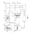
- FIG. 7 is a schematic diagram of a first preferred circuit that can be used to produce a three phase power supply in accordance with the present invention.
- FIGS. 8 to 11 are schematic diagrams of further preferred circuits that can each also be used to produce a three phase power supply in accordance with the invention.
- the present invention relates to the conversion of a single electrical phasor into multiple electrical phasors, in particular into three phasors, 120° or so, electrically apart with or without a common Neutral.
- the single phase supply source is preferably an existing or new SWER system, or a single phase, ‘Two Phase Two Wire’, supply system, but suitable single phase power supply sources include, but are not limited to: electricity distribution supply systems; local or remote generators; wind, solar or wave energy sources; chemical or mechanical supply systems; and/or, any other suitable energy source that can be converted to a single phase electricity source.
- the present invention utilises an existing or new SWER power supply system, and/or, a single phase, ‘Two Phase Two Wire’, power supply system, to produce a three phase power supply
- new or other single phase supply systems could also be converted to three phase in accordance with the present invention.
- the invention should therefore not be construed as limited to the specific examples provided.
- FIG. 1 A schematic circuit diagram of a typical single SWER system 1 is shown in FIG. 1 .
- This Figure shows the use of a SWER transformer 9 that has a single primary and dual secondaries—where the secondaries are connected in a U-N-U configuration, i.e. U & U are 180 degrees apart, in relation to Neutral point (‘N’).
- SWER line 2 is a single conductor that may stretch for tens or even hundreds of kilometers or miles (as represented by the breaks in SWER line 2 and earth return path 5 ), with a number of distribution transformers 9 along its length.
- each transformer 9 such as at a consumer's premises, current flows from line 2 , through the primary coil of the step-down transformer 9 , to earth 5 through an earth stake (not shown). From the earth stake, the current eventually finds its way back to the main isolating transformer 3 at the head of the line, completing the circuit.
- the secondary windings of distribution transformer 9 will then supply the consumer with either single ended single phase (U-0 or U-N) power, or split phase (U-0-U or U-N-U) power, in the regions standard appliance voltages, with the ‘0’ or ‘N’ volt line connected to a safety earth 5′ that does not normally carry an operating current.
- Such additional components may include: recloser 6 ; surge arrestor 7 ; and, fuses 8 —such as high-rupture capacity (HRC) fuses.
- HRC high-rupture capacity
- transformer 9 When transformer 9 has a voltage applied across its primary winding, two secondary voltages are produced across the secondary coils of transformer 9 . This results in the generation of a single phase power supply which may be illustrated by the single phasor Va (or, (a)) shown in the phasor diagram of FIG. 3 (or angle references of FIG. 4 ).
- the present invention may utilise this existing (or new) single SWER power supply 1 to produce a three phase power supply that can readily be distributed to consumers in remote or rural areas.
- other power source supplies such as, for example, electricity distribution or solar power supplies, etc, may be used instead of, or in conjunction with, SWER system 1 in order to generate a three phase power supply in accordance with preferred embodiments of the invention.
- a suitable alternative preferred source is a single phase, ‘Two Phase Two Wire’ supply system ( 10 ).
- a schematic circuit diagram of a typical single phase, ‘Two Phase Two Wire’, supply system 10 is shown in FIG. 2 .
- This Figure shows the use of two distribution transformers ( 20 , 30 ) that have single primaries and dual secondaries—where the secondaries are connected in a: U-N-U configuration, i.e. U & U are 180 degrees apart, in relation to Neutral point (‘N’), or U-N configuration, respectively.
- the present invention may utilise this existing (or new) single phase, ‘Two Phase Two Wire’, power supply 10 to produce a three phase power supply that can readily be distributed to consumers in remote or rural areas.
- this existing (or new) single phase, ‘Two Phase Two Wire’, power supply 10 may be used instead of, or in conjunction with, single phase system 10 in order to generate a three phase power supply in accordance with preferred embodiments of the invention.
- the basic concept of an electrical transformer is to have at least one primary winding and at least one secondary winding, wrapped around one closed loop magnetic core.
- an alternating supply (AC) is connected to the primary, it creates alternating magnetic flux ⁇ that induces potential on the secondary's windings terminals.
- three single phase transformers can be built on one magnetic core that has three limbs. This can be achieved due to the fact that the total three phase flux equals zero.
- a single phase transformer with one primary winding wrapped around a magnetic core, and one, but preferably two, secondary windings on the same core may be utilised (see, for example, the preferred circuit embodiments shown in FIGS. 7 to 11 ).
- the secondaries can be arranged in either a cascaded or paralleled configuration.
- the second and third phases (Vb,Vc) are then reconstructed using one of the secondaries, cascaded with one or two external sources that are predetermined with amplitude and phase shift, so that each combination provides a new amplitude and the phase is shifted to achieve around 120° separation with the same magnitude of amplitude.
- phase supply e.g. Va
- this phase may be designated as an essential supply for consumers' essential loads.
- the concept of phasor reconstruction may be provided by the following trigonometric equations (proof):
- Phasor Vb can be represented by two perpendicular components:
- Phasor Vc can be represented by two perpendicular components:
- various practical preferred circuits are provided for producing a three phase power supply from one or more single phase supply source(s), each utilising the novel phasor reconstruction principles provided hereinabove.
- various practical circuit embodiments 100 , 200 , 300 , 400 , 500
- same are only an example of the types of circuits that can be constructed in accordance with the invention in order to realise the novel phasor reconstruction principles provided above.
- other practical hardware implementations could also be used. Accordingly, the present invention should not be construed as limited to the specific examples provided herein.
- FIG. 7 there is shown a first preferred circuit 100 that may be used in accordance with the present invention to produce a three phase power supply from a single phase source.
- This preferred circuit 100 utilises a single phase transformer 110 that has a primary 115 ; a first secondary 120 that has an amplitude of unity, and second secondary 125 that has an amplitude of half of unity.
- FIGS. 3 to 6 show the respective phasors and angle references produced by preferred circuit 100 . More particularly: in FIGS. 3 & 4 , Va or (a) represents the unity output phasor from transformer 110 ; in FIGS. 5 & 6 , (ii) is the half unity phasor produced by second secondary 125 of transformer 110 ; again in FIGS.
- (i) is the potential between the terminals 160 & 165 of a first external power supply 130 , which is 0.866 of the unity value, at 90°, with reference to Va or (a) of FIGS. 3 & 4 ; and, yet again in FIGS. 5 & 6 , (iii) is the potential between terminals 170 & 175 of a second external power supply 140 , which is 0.866 of the unity value, at 270°, with reference to Va or (a) of FIGS. 3 & 4 .
- both external power supplies 130 , 140 are controlled by an inverter controller box 150 , via control lines 180 & 185 respectively, for amplitude and phase shift, by sensing all three phase outputs Va (a), Vb (b), Vc (c), and common Neutral ‘N’.
- preferred circuit 100 has an input 115 (to transformer 110 ) from a power supply source (which may be either of single phase supply sources 1 , 10 described above with reference to FIGS. 1 & 2 , or any other suitable supply source), and two independent floating outputs provided by external supply power supplies 130 , 140 .
- a power supply source which may be either of single phase supply sources 1 , 10 described above with reference to FIGS. 1 & 2 , or any other suitable supply source
- External power supplies 130 , 140 can be any suitable supply source including SWER system 1 , single phase system 10 (e.g. Two Phase Two Wire), or any other suitable source as described above.
- external power supplies 130 , 140 could simply be self-supplied by transformer 110 of preferred circuit 100 .
- the combined circuit 100 of transformer 110 and inverter controller box 150 produces an electricity supply of three phases, 120° or so separated, and a common Neutral (‘N’).
- N common Neutral
- FIGS. 3 & 4 for the respective phasors and angle references produced (i.e. Va (a), Vb (b), Vc (c)).
- inverter controller box 150 includes a number of components to ensure that the resultant three phase supply is reliable and stable.
- a 90° phase shifter is preferably utilised within inverter controller box 150 to provide phase angle balance.
- the phase shifter is preferably Phase Locked Loop (PLL) with the input/output phase Va (a), hence any internal phase shift (due to, for example, the windings impedance phase shift) is compensated by the PLL.
- PLL Phase Locked Loop
- the remaining electronic components can include an active rectifier (see, for example, item 335 in FIG. 9 ) that minimises harmonic distortion, along with line filters within the active rectifier (again, item 335 in FIG. 9 ) on its input and output.
- the output voltage from the inverter controller box 150 is 0.866 of the unconverted phase voltage, and tracking. This means that for any voltage change of the unconverted source phase Va, the output of the inverter controller box 150 tracks with its output voltage and the actual phase shift in a way that the output voltage of the reconstructed phases (i.e. Vb,Vc) will keep their voltage and phase angle balanced.
- FIG. 8 there is shown a second preferred circuit 200 that may also be used in accordance with the present invention to produce a three phase power supply from one or more single phase source(s).
- second preferred circuit 200 of FIG. 8 is very similar to that of first preferred circuit 100 shown in FIG. 7 , and only differs with respect to transformer 210 . That is, transformer 210 only has one secondary 220 .
- FIG. 9 there is shown a third preferred circuit 300 that may also be used in accordance with the present invention to produce a three phase power supply from one or more single phase source(s).
- third preferred circuit 300 like reference numerals to those used in FIGS. 7 & 8 to describe the first and second preferred circuits 100 , 200 are used to denote like parts of the third preferred circuit 300 .
- Third preferred circuit 300 of FIG. 9 is again similar to that of first preferred circuit 100 shown in FIG. 7 , and only differs with respect to the external power supplies. That is, in preferred circuit 300 instead of having two external power supplies (e.g. 130 , 140 in FIG. 7 ), circuit 300 now includes three separate blocks 335 , 336 , 337 .
- a first block 335 is an efficient power supply containing an active rectifier.
- the second and third blocks 336 , 337 are inverters which each produce 0 . 866 unity potential, at 90° and 270° respectively. Both are commonly connected to transformer ( 310 ) secondary 325 which then creates the output potential Vb (b) and Vc (c) respectively.
- FIG. 10 there is shown a fourth preferred circuit 400 that may also be used in accordance with the present invention to produce a three phase power supply from one or more single phase source(s).
- FIG. 10 like reference numerals to those used in FIGS. 7 to 9 to describe the first to third preferred circuits 100 , 200 , 300 are used to denote like parts of the fourth preferred circuit 400 .
- Fourth preferred circuit 400 of FIG. 10 is again similar to that of first preferred circuit 100 shown in FIG. 7 , and again only differs with respect to the external power supplies.
- This particular circuit embodiment 400 is considered the most efficient practical application of the invention, as it requires only one power supply 435 which includes an inverter of 90°, which drives a primary 412 of a second transformer 411 , which transformer 411 has split secondaries 413 , 414 each connected to secondary 425 of first transformer 410 .
- This configuration again like in previous embodiments, creates Vb (b) and Vc (c) respectively.
- FIG. 11 there is shown a fifth preferred circuit 500 that may also be used in accordance with the present invention to produce a three phase power supply from one or more single phase source(s).
- FIG. 11 like reference numerals to those used in FIGS. 7 to 10 to describe the first to fourth preferred circuits 100 , 200 , 300 , 400 are used to denote like parts of the fifth preferred circuit 500 .
- Fifth preferred circuit 500 of FIG. 11 is similar to that of fourth preferred circuit 400 shown in FIG. 10 , and only differs with respect to first transformer 510 .
- This particular circuit embodiment 500 is again considered to be a pragmatic and economical implementation of the invention, as it has a similar construction to that of circuit 400 of FIG. 10 .
- first transformer 510 only has one secondary 520 , what would have otherwise been the second secondary (e.g. 425 in FIG. 10 ) has to be artificially created utilizing a third transformer 521 .
- This third transformer 521 has a single unity primary 522 , and a single secondary 523 at half unity.
- This configuration again like in previous embodiments, creates Vb (b) and Vc (c) respectively.
- This configuration is particularly suited as an add-on unit for existing widely installed SWER systems ( 1 ) or single phase Two Wire systems ( 10 ).
- the invention provides at least four novel approaches to producing a three phase supply from a single phase source.
- a first novel approach relates to the power utilised by the circuits. That is, the power put through the preferred circuits ( 100 , 200 , 300 , 400 , 500 ) of the invention, is divided into approximately two halves. One half is used as a part of the output power, and the other half is used to supply an inverter that generates a sine like wave, having a 90° phase shift. Hence, only about 50% of the input supply power is used for conversion purposes, and the other 50% remains as is as it does not go through the process of conversion.
- the conversion efficiency is much higher than existing inverters that convert the full input power into output power, and, the power quality of the three phase output can be kept very high as the amplitude and the phase shift is synchronised with the non-inverted phase, hence negative sequence and balance are kept very accurately.
- a second novel approach is that if any part of the preferred conversion circuits ( 100 , 200 , 300 , 400 , 500 ) fail, the main phase (e.g. Va) that passes through the circuits ( 100 , 200 , 300 , 400 , 500 ) remains intact for essential services.
- the main phase e.g. Va
- a third novel approach relates the Electro Magnetic Compatibility (“EMC”) of the preferred circuits 100 , 200 , 300 , 400 , 500 . That is, the EMC of the inverter input is kept very efficient as the front end of the inverter is made with a filtered active rectifier that generates back into the source of supply very low harmonic distortion.
- EMC Electro Magnetic Compatibility
- a fourth novel aspect relates to the fact that the preferred inverter circuits have to generate no more than 86.66% of the existing phase amplitude. In power terms this is 25% less conversion losses compared to converting circuits that have to generate 100% of the output amplitude. Further, the fact that the inverter does not have to generate 100% at 90°, but only 86.66%, allows for the inverter controller box to track the input/output non-inverted phase by amplitude and angle, hence allowing the inverter to adjust its amplitude and angle, allowing amplitude balance and 120° accurate separation between the three phases (i.e. Va,Vb,Vc). By having this ability of tracking, very high power quality parameters can be achieved, leading to a high efficiency operating system (i.e.
- the circuits ( 100 , 200 , 300 , 400 , 500 ) adjust themselves, in a manner that the 86.66% amplitude at 90° can vary and become 95% at 85° or 95°, depending on the load type and its impact on the input/output phase amplitude and transformer internal impedance.
- the purpose of the usage of the circuits ( 100 , 200 , 300 , 400 , 500 ) is mainly to drive three phase loads, then a simpler version of conversion can be applied. This is by using only one 90° phase shifting, and using a split transformer to create the complimentary 180° which leads to 270° shift, required for the third phase reconstruction. This is also applicable for a large distribution centre connected to many loads that statistically has a balanced current draw.
- converting circuits ( 100 , 200 , 300 , 400 , 500 ) of the present invention can be built in various ways, including: Mechanical—where the elected phase shifted component is achieved by running mechanical means to rotate an AC single phase or two phase synchronized generator to complete the missing electrical phases.
- the electrical generator can be driven by hydraulics, a fuel operated engine, etc; or, Electrical—where a synchronized generator is driven by an electrical motor operated by the existing source of electrical supply or by an external source of electrical supply; or, by Electronic means that converts the electrical supply from what it is into just the required portion of the shifted component of the reconstructed electrical phases.
- the converting apparatus and methods of the invention can be implemented in many ways, not necessarily just for conversion of a single phase supply into a three phase supply at a customer's point of supply—as in the case of existing solutions described above. Instead, implementation can occur also in large scale applications, for example, within electricity distribution networks at various voltages and power capacities. This can also be used to convert a part of a single phase transmission/distribution line into a three phase transmission/distribution line.
- the invention may also be incorporated into a single phase high voltage regulator, which may be used in a certain location of a transmission/distribution single phase line, and continue the line as a regulated three phase line. This is especially beneficial where SWER systems are used and the ground connection impedance is relatively high.
- the single phase to three phase conversion can be done either at the local point of supply for a consumer, or much further backwards at a point where it is desired to change the distribution network from single phase into a three phase supply, as the conversion methodology of the present invention can work either from low voltages to high voltages.
- the methods and apparatus of the present invention provide many advantages to the power supply industry. Most importantly the present invention provides means in which existing SWER ( 1 ) or other single phase systems, e.g. ‘Two Phase Two Wire’ systems 10 , etc, can be adapted to supply three phase power to remote or rural consumers.
- SWER 1
- other single phase systems e.g. ‘Two Phase Two Wire’ systems 10 , etc.
- the proposed converting methods/apparatus can be used either to directly operate three phase induction motors by having a supply source of a single phase only, and/or converting a distribution system into three phase having 3 or 4 wires.
- the preferred method is, however, to provide a 4 wire three phase system, as this allows the connection of either multiple single phase loads or multiple three phase loads, and also allows operation in unbalanced conditions. Furthermore, it provides a means of allowing the installation of protection devices for prevention of electrocution, such devices being normally used in the electrical supply industry.
- Having a Common Neutral (‘N’) in other solutions requires additional means as, for example, a neutral transformer.
- Voltage balance at imbalanced loads is especially essential in induction motors in order to prevent Negative Sequence, a phenomena that causes significant deficiencies and induction motor excessive heat.
- the point of common coupling is the point where the electricity utility connects to the private asset of the customer.
- the present invention is designed for meeting strict Harmonic limitations. 6.
- the present invention is preferably for electricity distribution at low to medium voltages. 7.
- the portion of converted/processed energy of the converter's output is around 50%. The other 50% or so of the output is non-converted.
- the present invention does not require any electromechanical and/or moving parts/components.
Abstract
Description
Va=A*sin(ωt+0°); (a)
Vb=B*sin(ωt+120°); (b)
Vc=C*sin(ωt+2400); (c)
Where; ωt+0° describes an angle that keeps changing in time with an offset of 0° from a known reference; ωt+120° describes an angle that keeps changing in time with an offset of 120° from the same known reference; and, ωt+240° describes an angle that keeps changing in time with an offset of 240° from the same known reference. The frequency of alternations is determined by ω (radians/sec); and A, B, & C represent the amplitude of the voltage value. In this example A=B=C=Unity.
Vbx=cos(30)*Vb*sin(wt+90°); and
Vby=sin(30)*Vb*sin(wt+180°). Hence:
Vbx=0.866*Vb*sin(wt+90°); and
Vby=0.5*Vb*sin(wt+180°).
Vcx=cos(30)*Vc*sin(wt+270°); and
Vcy=sin(30)*Vc*sin(wt+180°). Hence:
Vcx=0.866*Vc*sin(wt+270°); and
Vcy=0.5*Vc*sin(wt+180°).
-
- Vby equals Vcy equals 0.5*Vc*sin(wt+180°); and
- Vbx amplitude equals Vcx amplitude, however in opposite directions.
Preferred Circuit Embodiments:
| Present | ||||
| Specification: | Solution: | Other Solutions: | Note | |
| Three phase 4 wire | Yes | No | 1 | |
| system: L1, L2, L3, N | ||||
| Earth fault protection | Yes | No | — | |
| Individual phase operation | Yes | No | — | |
| Phase voltage balance at | Yes | Not apparent | 2 | |
| imbalanced load | ||||
| Phase angle balance at | Yes | Not apparent | 2 | |
| imbalance load | ||||
| Designated application | Multiple | Generally for | — | |
| applications | three phase | |||
| induction | ||||
| motors | ||||
| Failsafe-essential supply | Yes | No | 3 | |
| (continuity of operation) | ||||
| Preferable recommended | Electrical utility | At the load | 4 | |
| point of installation | side of the | |||
| point of | ||||
| common | ||||
| coupling | ||||
| Inverter Harmonic | Yes | No | 5 | |
| Distortion filtering | ||||
| Harmonic Distortion | No | Yes | 5 | |
| generation | ||||
| Implementation at | | No | 6 | |
| voltages higher than | ||||
| 1000 V | ||||
| Energy conversion index | Yes | No | 7 | |
| 50% vs. 100% | ||||
| Motor assisted converter | No | In certain | 8 | |
| applications | ||||
| Static coils/caps PLC | No | In certain | 8 | |
| controlled converters | applications | |||
| NOTES: | ||||
| 1. Having a Common Neutral (‘N’) in other solutions requires additional means as, for example, a neutral transformer. | ||||
| 2. Voltage balance at imbalanced loads is especially essential in induction motors in order to prevent Negative Sequence, a phenomena that causes significant deficiencies and induction motor excessive heat. | ||||
| 3. A difference between the proposed invention and other solutions, is that the main phase (the source single phase) is directly connected as one of the three phase outputs, hence in the case of conversion failure, essential single phase supply still continues. | ||||
| 4. The point of common coupling is the point where the electricity utility connects to the private asset of the customer. | ||||
| 5. The present invention is designed for meeting strict Harmonic limitations. | ||||
| 6. The present invention is preferably for electricity distribution at low to medium voltages. | ||||
| 7. The portion of converted/processed energy of the converter's output is around 50%. The other 50% or so of the output is non-converted. | ||||
| 8. The present invention does not require any electromechanical and/or moving parts/components. | ||||
Claims (16)
Priority Applications (1)
| Application Number | Priority Date | Filing Date | Title |
|---|---|---|---|
| US13/695,324 US9083235B2 (en) | 2010-05-11 | 2011-05-11 | Methods and apparatus for supplying three phase power |
Applications Claiming Priority (3)
| Application Number | Priority Date | Filing Date | Title |
|---|---|---|---|
| US33328810P | 2010-05-11 | 2010-05-11 | |
| PCT/AU2011/000545 WO2011140597A1 (en) | 2010-05-11 | 2011-05-11 | Methods and apparatus for supplying three phase power |
| US13/695,324 US9083235B2 (en) | 2010-05-11 | 2011-05-11 | Methods and apparatus for supplying three phase power |
Related Parent Applications (1)
| Application Number | Title | Priority Date | Filing Date |
|---|---|---|---|
| PCT/AU2011/000545 A-371-Of-International WO2011140597A1 (en) | 2010-05-11 | 2011-05-11 | Methods and apparatus for supplying three phase power |
Related Child Applications (1)
| Application Number | Title | Priority Date | Filing Date |
|---|---|---|---|
| US14/750,464 Continuation US9893640B2 (en) | 2010-05-11 | 2015-06-25 | Methods and apparatus for supplying three phase power |
Publications (2)
| Publication Number | Publication Date |
|---|---|
| US20130200862A1 US20130200862A1 (en) | 2013-08-08 |
| US9083235B2 true US9083235B2 (en) | 2015-07-14 |
Family
ID=44913762
Family Applications (2)
| Application Number | Title | Priority Date | Filing Date |
|---|---|---|---|
| US13/695,324 Active 2032-01-25 US9083235B2 (en) | 2010-05-11 | 2011-05-11 | Methods and apparatus for supplying three phase power |
| US14/750,464 Active US9893640B2 (en) | 2010-05-11 | 2015-06-25 | Methods and apparatus for supplying three phase power |
Family Applications After (1)
| Application Number | Title | Priority Date | Filing Date |
|---|---|---|---|
| US14/750,464 Active US9893640B2 (en) | 2010-05-11 | 2015-06-25 | Methods and apparatus for supplying three phase power |
Country Status (6)
| Country | Link |
|---|---|
| US (2) | US9083235B2 (en) |
| AP (2) | AP2015008816A0 (en) |
| AU (1) | AU2011252753B2 (en) |
| NZ (2) | NZ703741A (en) |
| WO (1) | WO2011140597A1 (en) |
| ZA (2) | ZA201209318B (en) |
Cited By (1)
| Publication number | Priority date | Publication date | Assignee | Title |
|---|---|---|---|---|
| US20220385201A1 (en) * | 2021-05-26 | 2022-12-01 | Sisu Devices Llc | Smart transformer device |
Families Citing this family (3)
| Publication number | Priority date | Publication date | Assignee | Title |
|---|---|---|---|---|
| NZ703741A (en) | 2010-05-11 | 2016-07-29 | Set Electrical Engineering Pty Ltd | Methods and apparatus for supplying three phase power |
| US11447027B2 (en) | 2019-07-19 | 2022-09-20 | Schneider Electric USA, Inc. | AC EVSE cluster load balancing system |
| US11955797B1 (en) | 2023-02-15 | 2024-04-09 | Zola Electric Labs Inc. | Methods and systems for managing power distribution in an electrical distribution network |
Citations (15)
| Publication number | Priority date | Publication date | Assignee | Title |
|---|---|---|---|---|
| US4100596A (en) | 1977-03-18 | 1978-07-11 | Sperry Rand Corporation | Protected aircraft power and phase converter |
| SU764061A1 (en) | 1975-06-13 | 1980-09-15 | Белорусский Ордена Трудового Красного Знамени Политехнический Институт | Single-phase-to-three-phase voltage converter |
| US4618809A (en) | 1984-06-08 | 1986-10-21 | Tokai Trw & Co., Ltd. | Apparatus for converting single-phase power to three-phase outputs |
| US4644241A (en) | 1984-06-08 | 1987-02-17 | Tokai Trw & Co., Ltd. | Single phase to three phase signal converter |
| US4777421A (en) * | 1987-06-12 | 1988-10-11 | Reed West | Phase converter for motor |
| US4899268A (en) * | 1989-05-10 | 1990-02-06 | Apc-Onsite, Inc. | Frequency-dependent single-phase to three-phase AC power conversion |
| US4908744A (en) | 1989-05-10 | 1990-03-13 | Apc-Onsite, Inc. | Frequency-independent single-phase to three-phase AC power conversion |
| US5272616A (en) | 1992-04-21 | 1993-12-21 | Wisconsin Alumni Research Foundation | Single phase to three phase power converter for motor loads |
| US5402053A (en) * | 1993-08-26 | 1995-03-28 | Wisconsin Alumni Research Foundation | Single phase to three phase converter capable of variable speed motor operation |
| US5545965A (en) * | 1994-07-25 | 1996-08-13 | Smith; Otto J. M. | Three phase motor operated from a single phase power supply and phase converter |
| US5969957A (en) | 1998-02-04 | 1999-10-19 | Soft Switching Technologies Corporation | Single phase to three phase converter |
| US6275405B1 (en) | 1998-12-11 | 2001-08-14 | General Electronics Applications, Inc. | Motor drive circuit |
| US6297971B1 (en) | 1999-05-05 | 2001-10-02 | Phase Technologies, Llc | Phase converter |
| US6831849B2 (en) | 2001-04-11 | 2004-12-14 | Meritor Light Vehicle Technology, Llc | Conversion of single phase to multiple phase alternating current |
| AU2006329365A1 (en) | 2005-12-26 | 2007-07-05 | Daikin Industries, Ltd. | Power conversion device and power conversion system |
Family Cites Families (5)
| Publication number | Priority date | Publication date | Assignee | Title |
|---|---|---|---|---|
| US464424A (en) * | 1891-12-01 | Railway-tie | ||
| US5537309A (en) * | 1991-06-28 | 1996-07-16 | Group Dekko International | Multi-phase and shifted phase power distribution systems |
| US5275405A (en) * | 1992-02-18 | 1994-01-04 | Club Pro Products, Inc. | Floor vent putting cup |
| US7511979B2 (en) * | 2005-08-12 | 2009-03-31 | Newman Jr Robert Charles | Automatic phase converter |
| NZ703741A (en) | 2010-05-11 | 2016-07-29 | Set Electrical Engineering Pty Ltd | Methods and apparatus for supplying three phase power |
-
2011
- 2011-05-11 NZ NZ703741A patent/NZ703741A/en unknown
- 2011-05-11 US US13/695,324 patent/US9083235B2/en active Active
- 2011-05-11 NZ NZ604016A patent/NZ604016A/en unknown
- 2011-05-11 AP AP2015008816A patent/AP2015008816A0/en unknown
- 2011-05-11 AU AU2011252753A patent/AU2011252753B2/en not_active Ceased
- 2011-05-11 AP AP2012006617A patent/AP3735A/en active
- 2011-05-11 WO PCT/AU2011/000545 patent/WO2011140597A1/en active Application Filing
-
2012
- 2012-12-10 ZA ZA2012/09318A patent/ZA201209318B/en unknown
-
2015
- 2015-06-25 US US14/750,464 patent/US9893640B2/en active Active
-
2019
- 2019-03-20 ZA ZA2019/01759A patent/ZA201901759B/en unknown
Patent Citations (17)
| Publication number | Priority date | Publication date | Assignee | Title |
|---|---|---|---|---|
| SU764061A1 (en) | 1975-06-13 | 1980-09-15 | Белорусский Ордена Трудового Красного Знамени Политехнический Институт | Single-phase-to-three-phase voltage converter |
| US4100596A (en) | 1977-03-18 | 1978-07-11 | Sperry Rand Corporation | Protected aircraft power and phase converter |
| US4618809A (en) | 1984-06-08 | 1986-10-21 | Tokai Trw & Co., Ltd. | Apparatus for converting single-phase power to three-phase outputs |
| US4644241A (en) | 1984-06-08 | 1987-02-17 | Tokai Trw & Co., Ltd. | Single phase to three phase signal converter |
| US4777421A (en) * | 1987-06-12 | 1988-10-11 | Reed West | Phase converter for motor |
| US4899268A (en) * | 1989-05-10 | 1990-02-06 | Apc-Onsite, Inc. | Frequency-dependent single-phase to three-phase AC power conversion |
| US4908744A (en) | 1989-05-10 | 1990-03-13 | Apc-Onsite, Inc. | Frequency-independent single-phase to three-phase AC power conversion |
| US5272616A (en) | 1992-04-21 | 1993-12-21 | Wisconsin Alumni Research Foundation | Single phase to three phase power converter for motor loads |
| US5402053A (en) * | 1993-08-26 | 1995-03-28 | Wisconsin Alumni Research Foundation | Single phase to three phase converter capable of variable speed motor operation |
| US5545965A (en) * | 1994-07-25 | 1996-08-13 | Smith; Otto J. M. | Three phase motor operated from a single phase power supply and phase converter |
| US5969957A (en) | 1998-02-04 | 1999-10-19 | Soft Switching Technologies Corporation | Single phase to three phase converter |
| US6275405B1 (en) | 1998-12-11 | 2001-08-14 | General Electronics Applications, Inc. | Motor drive circuit |
| US6297971B1 (en) | 1999-05-05 | 2001-10-02 | Phase Technologies, Llc | Phase converter |
| US6831849B2 (en) | 2001-04-11 | 2004-12-14 | Meritor Light Vehicle Technology, Llc | Conversion of single phase to multiple phase alternating current |
| AU2006329365A1 (en) | 2005-12-26 | 2007-07-05 | Daikin Industries, Ltd. | Power conversion device and power conversion system |
| US20090034305A1 (en) | 2005-12-26 | 2009-02-05 | Abdallah Mechi | Power Conversion Device and Power Conversion System |
| US8064232B2 (en) | 2005-12-26 | 2011-11-22 | Daikin Industries, Ltd. | Power conversion device and power conversion system |
Non-Patent Citations (12)
| Title |
|---|
| Bellar, M.D. et al. "Comparative analysis of single-phase to three-phase converters for rural electrification" IEEE International Symposium on Industrial Electronics, 2004 Issue Date: May 4-7, 2004, vol. 2, on pp. 1255-1260, Figure 12. |
| First Examination Report issued upon corresponding Australian Patent Application No. 2011252753 on Mar. 17, 2014. |
| First Examination Report issued upon corresponding New Zealand Patent Application No. 604016 on Jul. 12, 2013. |
| First Examination Report, Jan. 28, 2015, for New Zealand Divisional Patent Application No. 703741. |
| International Preliminary Report on Patentability (IPRP) published Nov. 13, 2012 for International Patent Application No. PCT/AU2011/000545 filed on May 11, 2011. |
| International Search Report (ISR) published Nov. 17, 2011 for International Patent Application No. PCT/AU2011/000545 filed on May 11, 2011. |
| Malengret, M. et al. "Applying Parks Transformation to a Single to Three Phase Convertor" IEEE Power Electronics Specialists Conference, 26th Annual IEEE PESC vol. 2 Jun. 18-22, 1995 pp. 985-989, Introduction Figures 2, 4, 6, 8. |
| Notice of Acceptance issued in connection with corresponding New Zealand Patent Application No. 604016, Jan. 23, 2015. |
| Ouyang, F., et al. "Research on a single-phase to three-phase power supply method based on balance transformer" Transactions of China Electrotechnical Society. vol. 23, No. 9, pp. 132-137. Sep. 2008, Abstract, figures 1, 2 Sections 2, 3.2 and 4.1, Equation 5. |
| Published specification, as accepted, for corresponding New Zealand Patent Application No. 604016, Jan. 30, 2015. |
| Terry Cockerill, Harris Impressed by Phase TEchnologies, Radio World, Dec. 16, 2009. |
| Written Opinion (WO) published Nov. 11, 2012 for International Patent Application No. PCT/AU2011/000545 filed on May 11, 2011. |
Cited By (1)
| Publication number | Priority date | Publication date | Assignee | Title |
|---|---|---|---|---|
| US20220385201A1 (en) * | 2021-05-26 | 2022-12-01 | Sisu Devices Llc | Smart transformer device |
Also Published As
| Publication number | Publication date |
|---|---|
| AU2011252753B2 (en) | 2015-04-02 |
| ZA201209318B (en) | 2019-06-26 |
| ZA201901759B (en) | 2021-01-27 |
| AP2012006617A0 (en) | 2012-12-31 |
| AP2015008816A0 (en) | 2015-10-31 |
| NZ703741A (en) | 2016-07-29 |
| US20130200862A1 (en) | 2013-08-08 |
| US9893640B2 (en) | 2018-02-13 |
| AP3735A (en) | 2016-06-30 |
| AU2011252753A1 (en) | 2013-01-10 |
| NZ604016A (en) | 2015-01-30 |
| US20150372608A1 (en) | 2015-12-24 |
| WO2011140597A1 (en) | 2011-11-17 |
Similar Documents
| Publication | Publication Date | Title |
|---|---|---|
| US9893640B2 (en) | Methods and apparatus for supplying three phase power | |
| JP2002528027A (en) | Power transmission equipment | |
| US8964423B2 (en) | Low weight 3-phase 5-output wire power conversion system for micro-grid | |
| CN107925358A (en) | Method and system for the current source high voltage direct current transmission system based on flue | |
| Das | Harmonic generation effects propagation and control | |
| Palanisamy et al. | Basic Electrical and Instrumentation Engineering | |
| Shertukde | Distributed photovoltaic grid transformers | |
| Fornari et al. | SSC compensation capability of unbalanced voltage sags | |
| AU2015203054B2 (en) | Methods and Apparatus for Supplying Three Phase Power | |
| Plummer | Assymmetry in distribution systems: causes, harmful effects and remedies | |
| RU2552377C2 (en) | Voltage balancer in three-phase network | |
| Trentini | The use of smart transfomer in the presence of dispersed generation | |
| CN109038993A (en) | A kind of all-in-one machine of integrated threephase alternator, transformer | |
| CN113632337B (en) | Method and system for AC power grid with increased power throughput | |
| CN209462235U (en) | A kind of all-in-one machine of integrated threephase alternator, transformer | |
| Klochikhin et al. | Balancing transformer for AC railway power supply | |
| GB2559413A (en) | Controlling voltage in electrical power distribution grid | |
| Gupta | Comprehensive STATCOM control for distribution and transmission system applications | |
| Boutora et al. | Analysis of the Disturbances in Distribution Networks using Matlab and ATP | |
| Kabalci et al. | Introduction to power systems | |
| Arora et al. | Understanding of Vector Group and Parallel operation of Three Phase Transformers | |
| US20200052490A1 (en) | Controlling voltage in electrical power distribution grid | |
| Mehrizi-Sani | Electrical Machines and Their Applications | |
| Batarseh | Components of electric energy systems | |
| Martins et al. | A modeling scheme for the Le Blanc transformer |
Legal Events
| Date | Code | Title | Description |
|---|---|---|---|
| AS | Assignment |
Owner name: SET ELECTRICAL ENGINEERING PTY LTD, AUSTRALIA Free format text: ASSIGNMENT OF ASSIGNORS INTEREST;ASSIGNOR:STEINBERG, SHMUEL;REEL/FRAME:029471/0356 Effective date: 20121121 |
|
| STCF | Information on status: patent grant |
Free format text: PATENTED CASE |
|
| MAFP | Maintenance fee payment |
Free format text: PAYMENT OF MAINTENANCE FEE, 4TH YR, SMALL ENTITY (ORIGINAL EVENT CODE: M2551); ENTITY STATUS OF PATENT OWNER: SMALL ENTITY Year of fee payment: 4 |
|
| AS | Assignment |
Owner name: TRIIION HOLDINGS PTY LTD, AUSTRALIA Free format text: ASSIGNMENT OF ASSIGNORS INTEREST;ASSIGNOR:SET ELECTRICAL ENGINEERING PTY LTD;REEL/FRAME:047983/0960 Effective date: 20181220 |
|
| FEPP | Fee payment procedure |
Free format text: MAINTENANCE FEE REMINDER MAILED (ORIGINAL EVENT CODE: REM.); ENTITY STATUS OF PATENT OWNER: SMALL ENTITY |
|
| FEPP | Fee payment procedure |
Free format text: 7.5 YR SURCHARGE - LATE PMT W/IN 6 MO, SMALL ENTITY (ORIGINAL EVENT CODE: M2555); ENTITY STATUS OF PATENT OWNER: SMALL ENTITY |
|
| MAFP | Maintenance fee payment |
Free format text: PAYMENT OF MAINTENANCE FEE, 8TH YR, SMALL ENTITY (ORIGINAL EVENT CODE: M2552); ENTITY STATUS OF PATENT OWNER: SMALL ENTITY Year of fee payment: 8 |