US8823206B2 - Power-supply control device - Google Patents
Power-supply control device Download PDFInfo
- Publication number
- US8823206B2 US8823206B2 US13/221,954 US201113221954A US8823206B2 US 8823206 B2 US8823206 B2 US 8823206B2 US 201113221954 A US201113221954 A US 201113221954A US 8823206 B2 US8823206 B2 US 8823206B2
- Authority
- US
- United States
- Prior art keywords
- power
- battery
- supply
- voltage battery
- voltage
- Prior art date
- Legal status (The legal status is an assumption and is not a legal conclusion. Google has not performed a legal analysis and makes no representation as to the accuracy of the status listed.)
- Active, expires
Links
Images


Classifications
-
- B—PERFORMING OPERATIONS; TRANSPORTING
- B60—VEHICLES IN GENERAL
- B60L—PROPULSION OF ELECTRICALLY-PROPELLED VEHICLES; SUPPLYING ELECTRIC POWER FOR AUXILIARY EQUIPMENT OF ELECTRICALLY-PROPELLED VEHICLES; ELECTRODYNAMIC BRAKE SYSTEMS FOR VEHICLES IN GENERAL; MAGNETIC SUSPENSION OR LEVITATION FOR VEHICLES; MONITORING OPERATING VARIABLES OF ELECTRICALLY-PROPELLED VEHICLES; ELECTRIC SAFETY DEVICES FOR ELECTRICALLY-PROPELLED VEHICLES
- B60L3/00—Electric devices on electrically-propelled vehicles for safety purposes; Monitoring operating variables, e.g. speed, deceleration or energy consumption
- B60L3/0023—Detecting, eliminating, remedying or compensating for drive train abnormalities, e.g. failures within the drive train
- B60L3/0046—Detecting, eliminating, remedying or compensating for drive train abnormalities, e.g. failures within the drive train relating to electric energy storage systems, e.g. batteries or capacitors
-
- B—PERFORMING OPERATIONS; TRANSPORTING
- B60—VEHICLES IN GENERAL
- B60L—PROPULSION OF ELECTRICALLY-PROPELLED VEHICLES; SUPPLYING ELECTRIC POWER FOR AUXILIARY EQUIPMENT OF ELECTRICALLY-PROPELLED VEHICLES; ELECTRODYNAMIC BRAKE SYSTEMS FOR VEHICLES IN GENERAL; MAGNETIC SUSPENSION OR LEVITATION FOR VEHICLES; MONITORING OPERATING VARIABLES OF ELECTRICALLY-PROPELLED VEHICLES; ELECTRIC SAFETY DEVICES FOR ELECTRICALLY-PROPELLED VEHICLES
- B60L3/00—Electric devices on electrically-propelled vehicles for safety purposes; Monitoring operating variables, e.g. speed, deceleration or energy consumption
- B60L3/04—Cutting off the power supply under fault conditions
-
- B—PERFORMING OPERATIONS; TRANSPORTING
- B60—VEHICLES IN GENERAL
- B60L—PROPULSION OF ELECTRICALLY-PROPELLED VEHICLES; SUPPLYING ELECTRIC POWER FOR AUXILIARY EQUIPMENT OF ELECTRICALLY-PROPELLED VEHICLES; ELECTRODYNAMIC BRAKE SYSTEMS FOR VEHICLES IN GENERAL; MAGNETIC SUSPENSION OR LEVITATION FOR VEHICLES; MONITORING OPERATING VARIABLES OF ELECTRICALLY-PROPELLED VEHICLES; ELECTRIC SAFETY DEVICES FOR ELECTRICALLY-PROPELLED VEHICLES
- B60L58/00—Methods or circuit arrangements for monitoring or controlling batteries or fuel cells, specially adapted for electric vehicles
- B60L58/10—Methods or circuit arrangements for monitoring or controlling batteries or fuel cells, specially adapted for electric vehicles for monitoring or controlling batteries
- B60L58/12—Methods or circuit arrangements for monitoring or controlling batteries or fuel cells, specially adapted for electric vehicles for monitoring or controlling batteries responding to state of charge [SoC]
-
- B—PERFORMING OPERATIONS; TRANSPORTING
- B60—VEHICLES IN GENERAL
- B60L—PROPULSION OF ELECTRICALLY-PROPELLED VEHICLES; SUPPLYING ELECTRIC POWER FOR AUXILIARY EQUIPMENT OF ELECTRICALLY-PROPELLED VEHICLES; ELECTRODYNAMIC BRAKE SYSTEMS FOR VEHICLES IN GENERAL; MAGNETIC SUSPENSION OR LEVITATION FOR VEHICLES; MONITORING OPERATING VARIABLES OF ELECTRICALLY-PROPELLED VEHICLES; ELECTRIC SAFETY DEVICES FOR ELECTRICALLY-PROPELLED VEHICLES
- B60L58/00—Methods or circuit arrangements for monitoring or controlling batteries or fuel cells, specially adapted for electric vehicles
- B60L58/10—Methods or circuit arrangements for monitoring or controlling batteries or fuel cells, specially adapted for electric vehicles for monitoring or controlling batteries
- B60L58/18—Methods or circuit arrangements for monitoring or controlling batteries or fuel cells, specially adapted for electric vehicles for monitoring or controlling batteries of two or more battery modules
-
- Y—GENERAL TAGGING OF NEW TECHNOLOGICAL DEVELOPMENTS; GENERAL TAGGING OF CROSS-SECTIONAL TECHNOLOGIES SPANNING OVER SEVERAL SECTIONS OF THE IPC; TECHNICAL SUBJECTS COVERED BY FORMER USPC CROSS-REFERENCE ART COLLECTIONS [XRACs] AND DIGESTS
- Y02—TECHNOLOGIES OR APPLICATIONS FOR MITIGATION OR ADAPTATION AGAINST CLIMATE CHANGE
- Y02T—CLIMATE CHANGE MITIGATION TECHNOLOGIES RELATED TO TRANSPORTATION
- Y02T10/00—Road transport of goods or passengers
- Y02T10/60—Other road transportation technologies with climate change mitigation effect
- Y02T10/70—Energy storage systems for electromobility, e.g. batteries
Definitions
- the present invention relates to a power-supply control device, and particularly relates to a power-supply control device that is suitably used to control a power supply of an electric-powered vehicle.
- a high-voltage battery and a low-voltage battery are usually provided in an electric-powered vehicle such as an EV (Electric Vehicle), an HEV (Hybrid Electric Vehicle), or a PHEV (Plug-in Hybrid Electric Vehicle).
- an electric-powered vehicle such as an EV (Electric Vehicle), an HEV (Hybrid Electric Vehicle), or a PHEV (Plug-in Hybrid Electric Vehicle).
- the high-voltage battery is mainly used as a power supply for a load of a high voltage (hereinafter, referred to as a high-voltage load) such as a main power motor for driving wheels of the electric-powered vehicle to travel and a compressor motor of an air conditioner.
- a high-voltage load such as a main power motor for driving wheels of the electric-powered vehicle to travel and a compressor motor of an air conditioner.
- the low-voltage battery is mainly used as a power supply for a load of a low voltage (hereinafter, referred to as a low-voltage load) such as various ECUs (Electronic Control Units) that control units of the electric-powered vehicle, EPSs (Electric Power Steerings), electric brakes, car audio devices, windshield wipers, and power windows, and an illumination lamp.
- a low-voltage load such as various ECUs (Electronic Control Units) that control units of the electric-powered vehicle, EPSs (Electric Power Steerings), electric brakes, car audio devices, windshield wipers, and power windows, and an illumination lamp.
- a DC-DC converter transforms the voltage of the high-voltage battery and supplies the voltage to the low-voltage battery.
- the high-voltage battery is directly connected to an input of a DC-DC converter control circuit that controls the DC-DC converter without interposing a relay, the DC-DC converter is started up to be able to charge the low-voltage battery even if the low-voltage battery has run out (for example, see Japanese Unexamined Patent Publication No. 2006-50779).
- a control device of the electric-powered vehicle includes the high-voltage battery, a booster that boosts up the voltage of the high-voltage battery to output the voltage onto a generator motor side, a step-down device that steps down the voltage supplied from the generator motor or the high-voltage battery to supply the voltage to the low-voltage battery, a first switch that is provided in one of positive and negative electrodes of the high-voltage battery, and a second switch that is provided in the other of the positive and negative electrodes.
- a power supply line for the step-down device is connected between the first switch and the booster and between the second switch and the high-voltage battery.
- the run-out of the low-voltage battery is prevented such that, when the generator motor breaks down, the low-voltage battery is continuously charged by the high-voltage battery through the step-down device while the step-down device is protected by turning off the first switch and such that, when the high-voltage battery breaks down, the low-voltage battery is continuously charged by the generator motor through the step-down device while the step-down device is protected by turning off the second switch (for example, see Japanese Unexamined Patent Publication No. 2007-28803).
- a vehicle power supply that supplies the power to a low-voltage system through the DC-DC converter while supplying the power to a high-voltage system from the high-voltage battery, in which a capacitor is charged when a relay switch that opens and closes connection among the high-voltage battery, the high-voltage system and the DC-DC converter, and the relay switch is turned on to be able to start up the high-voltage system and the low-voltage system using the power of the capacitor when the ignition switch is turned on, thereby eliminating the low-voltage battery (for example, see Japanese Unexamined Patent Publication No. 2005-287242).
- a voltage equal to or more than a rated voltage may be applied to each load including the DC-DC converter, thereby causing breakdown.
- a power-supply control device prevents breakdown of each load due to abnormalities of a high-voltage battery in starting supply of power from the high-voltage battery to each load.
- a power-supply control device including: a voltage conversion unit that steps down a voltage at a battery to supply the stepped-down voltage to a first load, the battery to which a plurality of cells are connected in series; a first opening and closing unit that opens and closes a supply path of first power from the battery to the voltage conversion unit and a second load; a battery control unit that detects abnormality of the battery, controls opening and closing of the first opening and closing unit, and is operated by second power supplied from the battery or third power supplied from the voltage conversion unit, the second power being lower than the first power; and a second opening and closing unit that opens and closes a supply path of the second power from the battery to the battery control unit, wherein the battery control unit controls opening and closing of the second opening and closing unit, the battery control unit opens the first opening and closing unit and detects the abnormality of the battery while closing the second opening and closing unit when the supply of the first power from the battery to the voltage conversion unit and the second load
- the first opening and closing unit is opened and the abnormality of the battery is detected while the second opening and closing unit is closed when the supply of the first power from the battery to the voltage conversion unit and the second load is started, the first opening and closing unit is closed while the second opening and closing unit is opened when the abnormality of the battery is not detected, and the first opening and closing unit is continuously opened when the abnormality of the battery is detected.
- the voltage conversion unit includes a DC-DC converter.
- the battery control unit includes an ECU.
- the first opening and closing unit and the second opening and closing unit include a relay, a switch, and the like.
- the second power may be supplied from some of the cells of the battery.
- a changing unit that changes the cells of the battery supplying the second power may further be provided.
- the changing unit includes a switch, a relay, and a transistor.
- a capacitor unit that is located between the second opening and closing unit and the battery control unit and charged by the second power may further be provided.
- the battery control unit may open the second opening and closing unit to close the first opening and closing unit when the abnormality of the battery is not detected.
- the power can continuously be supplied to the battery control unit to stably operate the battery control unit.
- the capacitor unit includes a capacitor, an electric double layer capacitor, and a secondary battery.
- the battery includes a plurality of cell groups having the same number of series-connected cells, and the power-supply control device further includes a changing unit that changes series connection and parallel connection among the plural cell groups, and the second power may be supplied from the plurality of parallel-connected cell groups.
- the cells of the battery can equally be used to further decrease the variation in charge amount of each cell.
- the changing unit includes a switch, a relay, and a transistor.
- the battery control unit closes the first opening and closing unit, and the battery control unit may open the second opening and closing unit after a signal indicating start of the supply of the third power is supplied from the voltage conversion unit.
- the power can more stably be supplied to the voltage conversion unit.
- the confirmation that the abnormality of the battery is not generated can be made before starting the supply of the power to each load.
- the breakdown of the load caused by the abnormality of the battery can be prevented at the start of the supply of the power from the battery.
- FIG. 1 is a circuit diagram illustrating a power-supply control system according to a first embodiment of the present invention
- FIG. 2 is a block diagram illustrating a configuration example of a function of a high-voltage battery control ECU
- FIG. 3 is a flowchart illustrating power-supply start-up processing
- FIG. 4 is a flowchart illustrating power-supply stop processing
- FIG. 5 is a circuit diagram illustrating a power-supply control system according to a second embodiment of the present invention.
- FIG. 6 is a block diagram illustrating a configuration example of a function of a high-voltage battery control ECU
- FIG. 7 is a flowchart illustrating power-supply start-up processing
- FIG. 8 is a flowchart illustrating power-supply stop processing
- FIG. 9 is a circuit diagram illustrating a power-supply control system according to a third embodiment of the present invention.
- FIG. 10 is a block diagram illustrating a configuration example of a function of a high-voltage battery control ECU
- FIG. 11 is a flowchart illustrating power-supply stop processing
- FIG. 12 is a circuit diagram illustrating a power-supply control system according to a fourth embodiment of the present invention.
- FIG. 13 is a block diagram illustrating a configuration example of a function of a high-voltage battery control ECU.
- FIG. 14 is a flowchart illustrating power-supply start-up processing
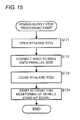
- FIG. 15 is a flowchart illustrating power-supply stop processing.
- FIGS. 1 to 4 A first embodiment of the present invention will be described with reference to FIGS. 1 to 4 .
- FIG. 1 is a circuit diagram illustrating a power-supply control system of the first embodiment of the present invention.
- a power-supply control system 101 is provided in an electric-powered vehicle.
- the power-supply control system 101 controls supply of power to a high-voltage load 102 , a low-voltage load 103 and n ECUs 104 - 1 to 104 - n , which are provided in the electric-powered vehicle, from a high-voltage battery 111 .
- the high-voltage load 102 includes a main power motor of the electric-powered vehicle and a compressor motor of an air conditioner.
- the low-voltage load 103 includes an ECU, an EPS, an electric brake, a car audio device, a windshield wiper, a power window motor and an illumination lamp, which need not be operated while the electric-powered vehicle is stopped.
- the ECUs 104 - 1 to 104 - n include ECUs, such as an accessory system, which need to be operated while the electric-powered vehicle is stopped.
- the ECUs 104 - 1 to 104 - n are simply referred to as ECU 104 when the ECUs need not be distinguished from one another.
- the power-supply control system 101 includes a high-voltage battery 111 , a DC-DC converter 112 , a voltage adjustment circuit 113 , a high-voltage battery control ECU (Electronic Control Unit) 114 , relays RY 1 a to RY 2 b , a diode D 1 and a capacitor C 1 .
- a high-voltage battery control ECU Electronic Control Unit
- the high-voltage battery 111 is a so-called assembled battery that includes a plurality of series-connected cells.
- Each cell of the high-voltage battery 111 includes a monitoring ECU that monitors a state of the cell, and the high-voltage battery 111 supplies information obtained from the monitoring ECU of each cell as battery state information to the high-voltage battery control ECU 114 .
- the battery state information includes a voltage, a current, a temporal change in current and a temperature of the whole high-voltage battery 111 or each cell and a battery capacity (state of charge) estimated from these pieces of information.
- a positive electrode of the high-voltage battery 111 is connected to the high-voltage load 102 and the DC-DC converter 112 through the relay RY 1 b .
- a negative electrode of the high-voltage battery 111 is connected to the high-voltage load 102 and the DC-DC converter 112 through the relay RY 1 a and also connected to a reference voltage point (for example, a body ground of the electric-powered vehicle) in the DC-DC converter 112 . Accordingly, the power of the high-voltage battery 111 is supplied to the high-voltage load 102 and the DC-DC converter 112 through the relays RY 1 a and RY 1 b.
- the relays RY 1 a to RY 1 b include normally open relays. Accordingly, in the relays RY 1 a to RY 1 b , a contact is opened to disconnect a high-voltage line that is a supply passage of the power from the high-voltage battery 111 to the high-voltage load 102 and the DC-DC converter 112 when a control voltage is not applied, and the contact is closed to establish the high-voltage line when the control voltage is applied.
- the relays RY 1 a to RY 1 b include so-called high-voltage main relays attached to the electric-powered vehicle.
- the DC-DC converter 112 steps down the voltage (for example, DC 334 V) of the high-voltage battery 111 to a predetermined voltage (for example, DC 14 V) and supplies the voltage to the low-voltage load 103 .
- the DC-DC converter 112 supplies the stepped-down voltage to a power supply 121 of the high-voltage battery control ECU 114 through the backflow preventing diode D 1 and the voltage adjustment circuit 113 .
- the DC-DC converter 112 supplies the stepped-down voltage to the ECU 104 through the diode D 1 . That is, the power outputted from the DC-DC converter 112 is supplied to the low-voltage load 103 , the high-voltage battery control ECU 114 and the ECU 104 .
- the DC-DC converter 112 includes an auxiliary power-supply circuit (not illustrated) therein, and obtains the power necessary for the operation by inputting the power from the high-voltage battery 111 to the auxiliary power-supply circuit.
- the end on the positive electrode side is connected to the power supply 121 of the high-voltage battery control ECU 114 through the relay RY 2 a and the voltage adjustment circuit 113 and connected to the ECU 104 through the relay RY 2 b .
- the end on the negative electrode side is connected to the high-voltage battery control ECU 114 through the relay RY 2 a and the voltage adjustment circuit 113 and connected to the reference voltage point in the high-voltage battery control ECU 114 .
- the power of the cell group CG of the high-voltage battery 111 is supplied to the high-voltage battery control ECU 114 through the relays RY 2 a and RY 2 b and the voltage adjustment circuit 113 and supplied to the ECU 104 through the relay RY 2 b.
- the cell group CG does not necessarily include a plurality of cells, but may include one cell.
- the end on the positive electrode side in both the ends of the cell group CG is referred to as a positive electrode of the cell group CG
- the end on the negative electrode side is referred to as a negative electrode of the cell group CG.
- the relays RY 2 a to RY 2 b include normally closed relays. Accordingly, in the relays RY 2 a to RY 2 b , the contact is closed to establish the power supply line from the cell group CG to the high-voltage battery control ECU 114 when the control voltage is not applied, and the contact is opened to disconnect the power supply line from the cell group CG to the high-voltage battery control ECU 114 when the control voltage is applied.
- the voltage adjustment circuit 113 includes a regulator IC.
- the voltage adjustment circuit 113 converts the voltage inputted from the cell group CG of the high-voltage battery 111 and the DC-DC converter 112 into a predetermined voltage (for example, 5 V) and supplies the converted voltage to the power supply 121 of the high-voltage battery control ECU 114 .
- the capacitor C 1 is connected in parallel between the voltage adjustment circuit 113 and the high-voltage battery control ECU 114 .
- the capacitor C 1 is charged by the power supplied from the cell group CG of the high-voltage battery 111 or the DC-DC converter 112 , and the capacitor C 1 is used as a backup power supply for the high-voltage battery control ECU 114 and the ECU 104 . That is, the power of the capacitor C 1 is supplied to the ECU 104 through the voltage adjustment circuit 113 while supplied to the high-voltage battery control ECU 114 .
- a capacitor device such as an electric double layer capacitor or a dischargeable and chargeable secondary battery having a small capacity may be used instead of the capacitor C 1 .
- the high-voltage battery control ECU 114 includes an MPU (Micro Processing Unit).
- the high-voltage battery control ECU 114 detects the abnormalities of the high-voltage battery 111 based on the battery state information supplied from the high-voltage battery 111 .
- the high-voltage battery control ECU 114 controls the relays RY 1 a and RY 2 b to control the supply of the power from the high-voltage battery 111 to the high-voltage load 102 and the DC-DC converter 112 based on a vehicle start-up signal and a vehicle stop signal supplied from an ignition switch (not illustrated) or a start switch (not illustrated) of the electric-powered vehicle and the presence or absence of the abnormalities of the high-voltage battery 111 .
- the power supply 121 of the high-voltage battery control ECU 114 supplies the power, supplied from the cell group CG of the high-voltage battery 111 , the DC-DC converter 112 or the capacitor C 1 , to each unit of the high-voltage battery control ECU 114 to operate the high-voltage battery control ECU 114 .
- the high-voltage battery control ECU 114 controls the relays RY 1 a and RY 2 b to switch the supply source of the power operating the high-voltage battery control ECU 114 .
- FIG. 2 is a block diagram illustrating a configuration example of a function of the high-voltage battery control ECU 114 .
- the high-voltage battery control ECU 114 includes a vehicle start-up/stop monitor 151 , a high-voltage battery monitor 152 , a power-supply controller 153 and a high-voltage output controller 154 .
- the vehicle start-up/stop monitor 151 monitors the states of the vehicle start-up signal and vehicle stop signal, which are supplied from the ignition switch or start switch of the electric-powered vehicle.
- the vehicle start-up/stop monitor 151 notifies the high-voltage battery monitor 152 , the power-supply controller 153 and the high-voltage output controller 154 of the state of each signal as necessary.
- the vehicle start-up signal and the vehicle stop signal may be implemented by different signals or by different states of one signal (for example, one of the states is High and the other is Low).
- the high-voltage battery monitor 152 detects the presence or absence of the abnormalities of the high-voltage battery 111 based on the battery state information supplied from the high-voltage battery 111 .
- the high-voltage battery monitor 152 notifies the power-supply controller 153 , the high-voltage output controller 154 and the ECU 104 of the detection result.
- the power-supply controller 153 controls the relays RY 2 a and RY 2 b to control the establishment and disconnection of the power supply line from the cell group CG of the high-voltage battery 111 to the high-voltage battery control ECU 114 and the ECU 104 .
- the power-supply controller 153 notifies the high-voltage output controller 154 of the states of the relays RY 2 a and RY 2 b as necessary.
- the high-voltage output controller 154 controls the relays RY 1 a and RY 1 b to establish and disconnect the high-voltage line.
- the high-voltage output controller 154 notifies the power-supply controller 153 of the states of the relays RY 1 a and RY 1 b as necessary.
- the power-supply start-up processing is performed when the ignition switch or start switch of the electric-powered vehicle is turned off while the power supply of the electric-powered vehicle is turned off.
- the relays RY 2 a and RY 2 b are closed (turned on) while the relays RY 1 a and RY 1 b are opened (turned off).
- the high-voltage line is disconnected while the power is supplied from the cell group CG of the high-voltage battery 111 to the high-voltage battery control ECU 114 and the ECU 104 .
- the capacitor C 1 is charged by the power of the cell group CG of the high-voltage battery 111 .
- step S 1 the high-voltage battery control ECU 114 intermittently monitors the vehicle start-up signal. Specifically, when the power supply of the electric-powered vehicle is turned off, the high-voltage battery control ECU 114 is started up with a predetermined period (for example, period of 1 ms) using the power of the cell group CG of the high-voltage battery 111 . Every time the high-voltage battery control ECU 114 is started up, the vehicle start-up/stop monitor 151 detects the presence or absence of the input of the vehicle start-up signal.
- a predetermined period for example, period of 1 ms
- the power consumption of the high-voltage battery control ECU 114 of the parked car can be suppressed by intermittently monitoring the vehicle start-up signal in this manner.
- step S 2 the vehicle start-up/stop monitor 151 determines whether the vehicle start-up signal is inputted. When the vehicle start-up signal is not inputted, the flow returns to step S 1 . Then, in step S 2 , the pieces of processing in steps S 1 and S 2 are repeatedly performed until determination is made that the vehicle start-up signal is inputted.
- step S 2 when the ignition switch or start switch of the electric-powered vehicle is turned on to input the vehicle start-up signal to the vehicle start-up/stop monitor 151 , the determination that the vehicle start-up signal is input is made in step S 2 , and the flow goes to step S 3 .
- step S 3 the high-voltage battery control ECU 114 stops the intermittent operation to start the continuous operation. At this point, the high-voltage battery control ECU 114 is continuously operated by the power supplied from the cell group CG of the high-voltage battery 111 .
- step S 4 the high-voltage battery monitor 152 detects the state of the high-voltage battery 111 based on the battery state information supplied from the high-voltage battery 111 .
- step S 5 the high-voltage battery monitor 152 determines whether the high-voltage battery 111 can be used based on the result of the processing in step S 4 .
- the high-voltage battery monitor 152 determines that the high-voltage battery 111 can be used, and the flow goes to step S 6 .
- the high-voltage battery monitor 152 notifies the power-supply controller 153 and the high-voltage output controller 154 that the high-voltage battery 111 can be used.
- step S 6 the power-supply controller 153 opens the relays RY 2 a and RY 2 b . Therefore, the cell group CG of the high-voltage battery 111 is separated from the high-voltage battery control ECU 114 and the ECU 104 to stop the supply of the power from the cell group CG to the high-voltage battery control ECU 114 and the ECU 104 . At this point, because the capacitor C 1 is charged, the high-voltage battery control ECU 114 and the ECU 104 is continuously operated by the power supplied from the capacitor C 1 . The power-supply controller 153 notifies the high-voltage output controller 154 that the relays RY 2 a and RY 2 b are opened.
- step S 7 the high-voltage output controller 154 closes the relays RY 1 a and RY 1 b . Therefore, the high-voltage line is established to start the supply of the power from the high-voltage battery 111 to the high-voltage load 102 and the DC-DC converter 112 .
- the loads except the load in which the power necessary for the operation is supplied from the DC-DC converter 112 are started up.
- step S 8 the DC-DC converter 112 starts the output. That is, the DC-DC converter 112 starts the processing of stepping down the voltage of the high-voltage battery 111 to a predetermined voltage to output the voltage. Therefore, the supply of the power from the DC-DC converter 112 to the low-voltage load 103 is started to start up the low-voltage load 103 , and the load in which the power necessary for the operation is supplied from the DC-DC converter 112 is started up in the high-voltage load 102 to start up the electric-powered vehicle.
- the supply of the power from the DC-DC converter 112 to the ECU 104 through the diode D 1 is started while the supply of the power from the DC-DC converter 112 to the high-voltage battery control ECU 114 through the diode D 1 and the voltage adjustment circuit 113 is started. Therefore, the high-voltage battery control ECU 114 and the ECU 104 are operated by the power supplied from the DC-DC converter 112 .
- the charge of the capacitor C 1 is started by the power supplied from the DC-DC converter 112 .
- step S 5 when the determination that the high-voltage battery 111 cannot be used is made in step S 5 , the flow goes to step S 9 .
- the high-voltage battery monitor 152 notifies the abnormalities of the high-voltage battery 111 .
- the high-voltage battery monitor 152 notifies the ECU 104 of the abnormalities of the high-voltage battery 111 , records abnormality information in a nonvolatile memory such as an EEPROM (Erasable Programmable ROM, not illustrated), and turns on an abnormality lamp (not illustrated) of an instrument panel of the electric-powered vehicle.
- EEPROM Erasable Programmable ROM
- the relays RY 2 a and RY 2 b are closed while the relays RY 1 a and RY 1 b remain in the open state, the electric-powered vehicle is not started up, and the power-supply start-up processing is ended.
- the power-supply stop processing is started, when the ignition switch or start switch of the electric-powered vehicle is turned off to input the vehicle stop signal to the vehicle start-up/stop monitor 151 in order to stop the electric-powered vehicle, or when the abnormalities of the high-voltage battery 111 are detected after the power-supply start-up processing of FIG. 3 .
- the relays RY 2 a and RY 2 b are opened while the relays RY 1 a and RY 1 b are closed. Accordingly, the power is supplied to the high-voltage battery control ECU 114 and the ECU 104 from the DC-DC converter 112 .
- the capacitor C 1 is charged by the power supplied from the DC-DC converter 112 .
- step S 21 the high-voltage output controller 154 opens the relays RY 1 a and RY 1 b . Therefore, the supply of the power from the high-voltage battery 111 to the high-voltage load 102 and the DC-DC converter 112 is stopped. The supply of the power from the DC-DC converter 112 to the low-voltage load 103 , the high-voltage battery control ECU 114 and the ECU 104 is stopped. At this point, because the capacitor C 1 is charged, the high-voltage battery control ECU 114 and the ECU 104 is continuously operated by the power supplied from the capacitor C 1 . The high-voltage output controller 154 notifies the power-supply controller 153 that the relays RY 1 a and RY 1 b are opened.
- step S 22 the power-supply controller 153 closes the relays RY 2 a and RY 2 b . Therefore, the supply of the power from the cell group CG of the high-voltage battery 111 to the high-voltage battery control ECU 114 and the ECU 104 is started. The charge of the capacitor C 1 is started by the power supplied from the cell group CG of the high-voltage battery 111 .
- step S 23 the high-voltage battery control ECU 114 starts the intermittent monitoring of the vehicle start-up signal.
- the power can reliably be supplied to the high-voltage battery control ECU 114 and the ECU 104 without providing the low-voltage battery, and therefore the high-voltage battery control ECU 114 and the ECU 104 can reliably be operated.
- the presence or absence of the abnormalities of the high-voltage battery 111 can reliably be detected before starting the supply of the power from the high-voltage battery 111 to the high-voltage load 102 and the DC-DC converter 112 , and the breakdowns of the high-voltage load 102 and the DC-DC converter 112 caused by the abnormalities of the high-voltage battery 111 are prevented.
- the capacitor C 1 desirably has a capacity that can stably supply the power to the high-voltage battery control ECU 114 and the ECU 104 while the supply source of the power to the high-voltage battery control ECU 114 and the ECU 104 changes from the cell group CG of the high-voltage battery 111 to the DC-DC converter 112 or while the supply source changes from the DC-DC converter 112 to the cell group CG.
- the capacitor C 1 has the capacity that can stably supply the power to at least the high-voltage battery control ECU 114 , the high-voltage line can reliably be established by continuing the operation of the high-voltage battery control ECU 114 even if the power of the ECU 104 is turned off to turn off the vehicle start-up signal.
- a capacitor unit similar to that of the capacitor C 1 may be provided in the ECU 104 .
- a countermeasure to preferentially charge the cell group CG is taken when the high-voltage battery 111 is charged by regeneration energy while the vehicle is running. Any method can be adopted as the charge amount equalizing control. The similar control may be performed during external charge while the vehicle is stopped.
- the high-voltage battery control ECU 114 (power-supply controller 153 ) actively closes the relays RY 2 a and RY 2 b in step S 22 by way of example.
- the relays RY 2 a and RY 2 b may wait after the relays RY 1 a and RY 1 b are opened. In such a case, after the capacitor C 1 is discharged, the relays RY 2 a and RY 2 b are automatically closed by turning off the power of the high-voltage battery control ECU 114 .
- FIGS. 5 to 8 A second embodiment of the present invention will be described with reference to FIGS. 5 to 8 .
- the capacitor C 1 of the power-supply control system 101 of FIG. 1 is eliminated in the second embodiment.
- FIG. 5 is a circuit diagram illustrating a power-supply control system of the second embodiment.
- the component corresponding to that of FIG. 1 is denoted by the same reference numeral, and the description of the same processing is omitted as appropriate.
- a power-supply control system 201 of FIG. 5 differs from the power-supply control system 101 of FIG. 1 only in that a DC-DC converter 211 and a high-voltage battery control ECU 212 are provided instead of the DC-DC converter 112 and the high-voltage battery control ECU 114 and that the capacitor C 1 is not provided.
- the DC-DC converter 211 differs from the DC-DC converter 112 of FIG. 1 only in that an output start signal indicating that the output is started is supplied to the high-voltage battery control ECU 212 .
- communication between the DC-DC converter 211 and the high-voltage battery control ECU 212 is implemented by serial communication, CAN (Controller Area Network) communication or LIN (Local Interconnect Network) communication.
- the high-voltage battery control ECU 212 differs from the high-voltage battery control ECU 114 of FIG. 1 only in that the supply source of the power with which the high-voltage battery control ECU 212 is operated is changed by controlling the relays RY 1 a to RY 2 b based on the output start signal of the DC-DC converter 211 .
- FIG. 6 is a block diagram illustrating a configuration example of a function of the high-voltage battery control ECU 212 .
- the component corresponding to that of FIG. 2 is denoted by the same reference numeral, and the description of the same processing is omitted as appropriate.
- the high-voltage battery control ECU 212 differs from the high-voltage battery control ECU 114 of FIG. 2 only in that a power-supply controller 251 is provided instead of the power-supply controller 153 .
- the power-supply controller 251 obtains the output start signal from the DC-DC converter 211 .
- the power-supply controller 153 controls the relays RY 2 a and RY 2 b to control the establishment and disconnection of the power supply line from the cell group CG of the high-voltage battery 111 to the high-voltage battery control ECU 212 and the ECU 104 .
- the power-supply controller 251 notifies the high-voltage output controller 154 of the states of the relays RY 2 a and RY 2 b as necessary.
- power-supply start-up processing performed by the power-supply control system 201 will be described with reference to a flowchart of FIG. 7 .
- the power-supply start-up processing is performed when the ignition switch or the start switch of the electric-powered vehicle while the power supply of the electric-powered vehicle is turned off.
- the relays RY 2 a and RY 2 b are closed while the relays RY 1 a and RY 1 b are opened. Accordingly, the high-voltage line is disconnected while the power is supplied from the cell group CG of the high-voltage battery 111 to the high-voltage battery control ECU 212 and the ECU 104 .
- steps S 51 to S 55 are similar to those in steps S 1 to S 5 of FIG. 3 , the description thereof will not be repeated.
- step S 55 When the determination that the high-voltage battery 111 can be used is made in step S 55 , the flow goes to step S 56 .
- step S 56 the relays RY 1 a and RY 1 b are closed similarly to the processing in step S 7 of FIG. 3 . Therefore, the high-voltage line is established to start the supply of the power from the high-voltage battery 111 to the high-voltage load 102 and the DC-DC converter 211 . In the high-voltage load 102 , the loads except the load in which the power necessary for the operation is supplied from the DC-DC converter 211 are started up.
- step S 57 the DC-DC converter 211 starts the output similarly to the processing in step S 8 of FIG. 3 . Therefore, the supply of the power from the DC-DC converter 211 to the low-voltage load 103 is started to start up the low-voltage load 103 , and the load in which the power necessary for the operation is supplied from the DC-DC converter 211 is started up in the high-voltage load 102 to start up the electric-powered vehicle.
- the supply of the power from the DC-DC converter 211 to the ECU 104 through the diode D 1 is started while the supply of the power from the DC-DC converter 211 to the high-voltage battery control ECU 212 through the diode D 1 and the voltage adjustment circuit 113 is started. Therefore, the high-voltage battery control ECU 212 and the ECU 104 are operated by the power supplied from the DC-DC converter 211 .
- step S 58 the power-supply controller 251 determines whether the output start signal is inputted. The determination processing in step S 58 is continued until the output start signal is inputted from the DC-DC converter 211 to the power-supply controller 251 , and the flow goes to step S 59 when the output start signal is inputted from the DC-DC converter 211 to the power-supply controller 251 .
- step S 59 the relays RY 2 a and RY 2 b are opened similarly to the processing in step S 6 of FIG. 3 . Therefore, the cell group CG of the high-voltage battery 111 is separated from the high-voltage battery control ECU 212 and the ECU 104 to stop the supply of the power from the cell group CG to the high-voltage battery control ECU 212 and the ECU 104 .
- the high-voltage battery control ECU 212 and the ECU 104 are continuously operated by the power supplied from the DC-DC converter 211 .
- step S 55 when the determination that the high-voltage battery 111 cannot be used is made in step S 55 , the flow goes to step S 60 .
- step S 60 the notification of the abnormality of the high-voltage battery 111 is made similarly to the processing in step S 9 of FIG. 3 .
- the relays RY 2 a and RY 2 b are closed while the relays RY 1 a and RY 1 b remain in the open state, the electric-powered vehicle is not started up, and the power-supply start-up processing is ended.
- the power-supply stop processing is started, when the ignition switch or the start switch of the electric-powered vehicle is turned off to input the vehicle stop signal to the vehicle start-up/stop monitor 151 in order to stop the electric-powered vehicle, or when the abnormalities of the high-voltage battery 111 are detected after the power-supply start-up processing of FIG. 7 .
- the relays RY 2 a and RY 2 b are opened while the relays RY 1 a and RY 1 b are closed. Accordingly, the power is supplied to the high-voltage battery control ECU 212 and the ECU 104 from the DC-DC converter 211 .
- step S 71 the power-supply controller 251 closes the relays RY 2 a and RY 2 b . Therefore, the supply of the power from the cell group CG of the high-voltage battery 111 to the high-voltage battery control ECU 212 and the ECU 104 is started.
- the power-supply controller 251 notifies the high-voltage output controller 154 that the relays RY 2 a and RY 2 b are closed.
- step S 72 the high-voltage output controller 154 opens the relays RY 1 a and RY 1 b . Therefore, the supply of the power from the high-voltage battery 111 to the high-voltage load 102 and the DC-DC converter 211 is stopped. The supply of the power from the DC-DC converter 211 to the low-voltage load 103 , the high-voltage battery control ECU 212 and the ECU 104 is stopped.
- step S 73 the intermittent monitoring of the vehicle start-up signal is started similarly to the processing in step S 23 of FIG. 4 .
- the power can always be supplied from the cell group CG of the high-voltage battery 111 or the DC-DC converter 211 to the high-voltage battery control ECU 212 and the ECU 104 without using the capacitor C 1 .
- the operations of the high-voltage battery control ECU 212 and ECU 104 can be stabilized as compared with the power-supply control system 101 .
- the power-supply stop processing may be performed according to the flowchart of FIG. 4 .
- the relays RY 1 a and RY 1 b may automatically be closed by turning off the power of the high-voltage battery control ECU 212 .
- FIGS. 9 to 11 A third embodiment of the present invention will be described with reference to FIGS. 9 to 11 .
- the cell group CG fixedly supplies the power to each ECU (high-voltage battery control ECU 114 , high-voltage battery control ECU 212 and ECU 104 ) by way of example. Therefore, degradation progresses earlier only in the cell group CG, a variation in charge amount is generated in the cells of the high-voltage battery 111 , and performance is possibly degraded in the whole of the high-voltage battery 111 .
- the application of the charge amount equalizing control as described above may be considered. However, it is more desirable that the power for operating each ECU is equally obtained from each cell of the high-voltage battery 111 by changing the cells that are used. In the third embodiment, the power for operating each ECU is equally obtained from each cell of the high-voltage battery 111 .
- FIG. 9 is a circuit diagram illustrating a power-supply control system of the third embodiment.
- the component corresponding to that of FIG. 1 is denoted by the same reference numeral, and the description of the same processing is omitted as appropriate.
- a power-supply control system 301 of FIG. 9 differs from the power-supply control system 101 of FIG. 1 only in that switches SW 11 to SW 22 are added and that a high-voltage battery control ECU 311 is provided instead of the high-voltage battery control ECU 114 .
- the cells of the high-voltage battery 111 are divided into four cell groups CG 1 to CG 4 .
- Each of the cell groups CG 1 to CG 4 has the same number of series-connected cells, and the cell groups CG 1 to CG 4 are equal to one another in the voltage at both ends.
- an end on the positive electrode side in both the ends of each cell group is referred to as a positive electrode of the cell group, and an end on the negative electrode side is referred to as a negative electrode of the cell group.
- the cell groups CG 1 to CG 4 are simply referred to as a cell group CG when the cell groups need not be distinguished from one another.
- the switch SW 11 can be connected to one of contacts CP 11 and CP 12 .
- the switch SW 12 can be connected to one of contacts CP 12 and CP 13 .
- the switch SW 13 can be connected to one of contacts CP 13 and CP 14 .
- the switch SW 14 can be connected to one of contacts CP 14 and CP 15 .
- the contact CP 11 is connected to the negative electrode of the cell group CG 1 .
- the contact CP 12 is connected to the positive electrode of the cell group CG 1 and the negative electrode of the cell group CG 2 .
- the contact CP 13 is connected to the positive electrode of the cell group CG 2 and the negative electrode of the cell group CG 3 .
- the contact CP 14 is connected to the positive electrode of the cell group CG 3 and the negative electrode of the cell group CG 4 .
- the contact CP 15 is connected to the positive electrode of the cell group CG 4 .
- the switch SW 21 can be connected to one of contacts CP 21 a and CP 21 b .
- the switch SW 22 can be connected to one of contacts CP 22 a and CP 22 b.
- the contact CP 21 a is connected to the switch SW 11 .
- the contact CP 21 b is connected to the switch SW 13 .
- the contact CP 22 a is connected to the switch SW 12 .
- the contact CP 22 b is connected to the switch SW 14 .
- the high-voltage battery control ECU 311 has a function of controlling the switches SW 11 to SW 22 to select the cell group CG of the high-voltage battery 111 that supplies the power to each ECU in addition to the function of the high-voltage battery control ECU 114 of FIG. 1 .
- FIG. 10 is a block diagram illustrating a configuration example of a function of the high-voltage battery control ECU 311 .
- the component corresponding to that of FIG. 2 is denoted by the same reference numeral, and the description of the same processing is omitted as appropriate.
- the high-voltage battery control ECU 311 differs from the high-voltage battery control ECU 114 of FIG. 2 only in that a power-supply controller 351 is provided instead of the power-supply controller 153 .
- the power-supply controller 351 has a function of controlling the switches SW 11 to SW 22 to select the cell group CG of the high-voltage battery 111 that supplies the power to each ECU in addition to the function of the power-supply controller 153 of FIG. 2 .
- the power-supply stop processing is started, when the ignition switch or start switch of the electric-powered vehicle is turned off to input the vehicle stop signal to the vehicle start-up/stop monitor 151 in order to stop the electric-powered vehicle, or when the abnormalities of the high-voltage battery 111 are detected after the power-supply start-up processing of FIG. 3 .
- the relays RY 2 a and RY 2 b are opened while the relays RY 1 a and RY 1 b are closed. Accordingly, the power is supplied to the high-voltage battery control ECU 311 and the ECU 104 from the DC-DC converter 112 .
- the capacitor C 1 is charged by the power supplied from the DC-DC converter 112 .
- step S 101 the high-voltage battery monitor 152 determines which cell group CG has the largest charge amount based on the battery state information supplied from the high-voltage battery 111 .
- the flow goes to step S 102 .
- the high-voltage battery monitor 152 notifies the power-supply controller 351 that the cell group CG 1 is the cell group CG having the largest charge amount.
- step S 102 the power-supply controller 351 connects the switch SW 11 to the contact CP 11 and connects the switch SW 12 to the contact CP 12 . Then the processing goes to step S 104 .
- step S 101 When the determination is made in step S 101 that the cell group CG 2 is the cell group CG having the largest charge amount, the flow goes to step S 103 . At this point, the high-voltage battery monitor 152 notifies the power-supply controller 351 that the cell group CG 2 is the cell group CG having the largest charge amount.
- step S 103 the power-supply controller 351 connects the switch SW 11 to the contact CP 12 and connects the switch SW 12 to the contact CP 13 . Then the processing goes to step S 104 .
- step S 104 the power-supply controller 351 connects the switch SW 21 to the contact CP 21 a and connects the switch SW 22 to the contact CP 22 a . Therefore, when the cell group CG 1 is determined as the cell group CG having the largest charge amount, the negative electrode of the cell group CG 1 is connected to the relay RY 2 a , and the positive electrode of the cell group CG 1 is connected to the relay RY 2 b . On the other hand, when the cell group CG 2 is determined as the cell group CG having the largest charge amount, the negative electrode of the cell group CG 2 is connected to the relay RY 2 a , and the positive electrode of the cell group CG 2 is connected to the relay RY 2 b . Then the processing goes to step S 108 .
- step S 101 When the determination is made in step S 101 that the cell group CG 3 is the cell group CG having the largest charge amount, the flow goes to step S 105 . At this point, the high-voltage battery monitor 152 notifies the power-supply controller 351 that the cell group CG 3 is the cell group CG having the largest charge amount.
- step S 105 the power-supply controller 351 connects the switch SW 13 to the contact CP 13 and connects the switch SW 14 to the contact CP 14 . Then, the processing goes to step S 107 .
- step S 101 When the determination is made in step S 101 that the cell group CG 4 is the cell group CG having the largest charge amount, the flow goes to step S 106 . At this point, the high-voltage battery monitor 152 notifies the power-supply controller 351 that the cell group CG 4 is the cell group CG having the largest charge amount.
- step S 106 the power-supply controller 351 connects the switch SW 13 to the contact CP 14 and connects the switch SW 14 to the contact CP 15 . Then, the processing goes to step S 107 .
- step S 107 the power-supply controller 351 connects the switch SW 21 to the contact CP 21 b and connects the switch SW 22 to the contact CP 22 b . Therefore, when the cell group CG 3 is determined as the cell group CG having the largest charge amount, the negative electrode of the cell group CG 3 is connected to the relay RY 2 a , and the positive electrode of the cell group CG 3 is connected to the relay RY 2 b . On the other hand, when the cell group CG 4 is determined as the cell group CG having the largest charge amount, the negative electrode of the cell group CG 4 is connected to the relay RY 2 a , and the positive electrode of the cell group CG 4 is connected to the relay RY 2 b . Then the processing goes to step S 108 .
- step S 108 the power-supply controller 351 closes the relays RY 2 a and RY 2 b . Therefore, the supply of the power from the cell group CG having the largest charge amount to the high-voltage battery control ECU 311 is started. The power-supply controller 351 then notifies the high-voltage output controller 154 that the relays RY 2 a and RY 2 b are closed.
- step S 109 the high-voltage output controller 154 opens the relays RY 1 a and RY 1 b . Therefore, the supply of the power from the high-voltage battery 111 to the high-voltage load 102 and the DC-DC converter 112 is stopped. The supply of the power from the DC-DC converter 112 to the low-voltage load 103 , the high-voltage battery control ECU 311 and the ECU 104 is stopped.
- step S 110 the intermittent monitoring of the vehicle start-up signal is started similarly to the processing in step S 23 of FIG. 4 .
- the cell group CG having the largest charge amount is always selected as the cell group CG for supplying the power to each ECU, which allows the variation in charge amount of each cell to decrease in the high-voltage battery 111 .
- the selected cell group CG may be stored in the high-voltage battery control ECU 311 or the nonvolatile memory in order to decrease the variation of the cell group CG to be used. For example, when the same cell group CG is continuously selected a predetermined number of times (for example, three times), the cell group CG having the second largest charge amount may be selected next even if the continuously selected cell group CG still has the largest charge amount.
- the high-voltage battery control ECU 311 controls the switches SW 11 to SW 22 by way of example.
- another ECU may control the switches SW 11 to SW 22 .
- a transistor or a relay may be used as the switches SW 11 to SW 22 .
- a three-state switch that is an open contact may be used as the switches SW 21 and SW 22 , and the relays RY 2 a and RY 2 b may be eliminated.
- the cell group CG used may automatically be rotated irrespective of the charge amount of each cell group CG, for example, in the order of the cell group CG 1 , the cell group CG 2 , the cell group CG 3 , the cell group CG 4 , the cell group CG 1 , and so on.
- the third embodiment is applied to the first embodiment by way of example.
- the third embodiment may also be applied to the second embodiment.
- the cells are divided into the four cell groups CG by way of example.
- the cells may be divided into the arbitrary number of cell groups CG according to the number of cells of the high-voltage battery 111 , the input voltage of the high-voltage battery control ECU 311 and the like. It is necessary to change the number of switches according to the number of cell groups CG.
- FIGS. 12 to 15 A fourth embodiment of the present invention will be described with reference to FIGS. 12 to 15 .
- the cells of the high-voltage battery 111 can equally be used compared with the third embodiment.
- FIG. 12 is a circuit diagram illustrating a power-supply control system of the fourth embodiment of the present invention.
- the component corresponding to that of FIG. 1 is denoted by the same reference numeral, and the description of the same processing is omitted as appropriate.
- a power-supply control system 401 of FIG. 12 differs from the power-supply control system 101 of FIG. 1 only in that a high-voltage battery 411 is provided instead of the high-voltage battery 111 and that a high-voltage battery control ECU 412 is provided instead of the high-voltage battery control ECU 114 .
- the high-voltage battery 411 differs from the high-voltage battery 111 of FIG. 1 in that switches SW 31 to SW 43 are incorporated therein. Similarly to the high-voltage battery 111 of FIG. 9 , the cells of the high-voltage battery 411 are divided into four cell groups CG 11 to CG 14 . Hereinafter, the cell groups CG 11 to CG 14 are simply referred to as a cell group CG when the cell groups need not be distinguished from one another.
- a supporting point FP 31 of the switch SW 31 is connected to the positive electrode of the cell group CG 11 , a contact CP 31 a is connected to the negative electrode of the cell group CG 12 , and a contact CP 31 b is connected to a contact CP 32 b of the switch SW 32 .
- a supporting point FP 32 of the switch SW 32 is connected to the positive electrode of the cell group CG 12 , a contact CP 32 a is connected to the negative electrode of the cell group CG 13 , and a contact CP 32 b is connected to a contact CP 33 b of the switch SW 33 .
- a supporting point FP 33 of the switch SW 33 is connected to the positive electrode of the cell group CG 13 , a contact CP 33 a is connected to the negative electrode of the cell group CG 14 , and a contact CP 33 b is connected to the positive electrode of the cell group CG 14 .
- a supporting point FP 41 of the switch SW 41 is connected to the negative electrode of the cell group CG 12 , a contact CP 41 a is connected to the positive electrode of the cell group CG 11 , and a contact CP 41 b is connected to the negative electrode of the cell group CG 11 .
- a supporting point FP 42 of the switch SW 42 is connected to the negative electrode of the cell group CG 13 , a contact CP 42 a is connected to the positive electrode of the cell group CG 12 , and a contact CP 42 b is connected to a contact CP 41 b of the switch SW 41 .
- a supporting point FP 43 of the switch SW 43 is connected to the negative electrode of the cell group CG 14 , a contact CP 43 a is connected to the positive electrode of the cell group CG 13 , and a contact CP 43 b is connected to a contact CP 42 b of the switch SW 42 .
- the switches SW 31 to SW 33 are connected to the contacts CP 31 a to CP 33 a , and the switches SW 41 to SW 43 are connected to the contacts CP 41 a to CP 43 a , whereby the cell groups CG 11 to CG 14 of the high-voltage battery 411 are connected in series.
- the switches SW 31 to SW 33 are connected to the contacts CP 31 b to CP 33 b
- the switches SW 41 to SW 43 are connected to the contacts CP 41 b to CP 43 b , whereby the cell groups CG 11 to CG 14 of the high-voltage battery 411 are connected in parallel.
- the high-voltage battery control ECU 412 has a function of controlling the switches SW 31 to SW 43 to change the series connection or the parallel connection of the cell group CG of the high-voltage battery 411 in addition to the function of the high-voltage battery control ECU 114 of FIG. 1 .
- FIG. 13 is a block diagram illustrating a configuration example of a function of the high-voltage battery control ECU 412 .
- the component corresponding to that of FIG. 2 is denoted by the same reference numeral, and the description of the same processing is omitted as appropriate.
- the high-voltage battery control ECU 412 differs from the high-voltage battery control ECU 114 of FIG. 2 in that a power-supply controller 451 is provided instead of the power-supply controller 153 .
- the power-supply controller 451 has a function of controlling the switches SW 31 to SW 43 to change the series connection or the parallel connection of the cell group CG of the high-voltage battery 411 in addition to the function of power-supply controller 153 of FIG. 2 .
- the power-supply start-up processing is performed when the ignition switch or start switch of the electric-powered vehicle is turned off while the power supply of the electric-powered vehicle is turned off.
- the relays RY 2 a and RY 2 b are closed, the relays RY 1 a and RY 1 b are opened, the switches SW 31 to SW 33 are connected to the contacts CP 31 b to CP 33 b , and the switches SW 41 to SW 43 are connected to the contacts CP 41 b to CP 43 b .
- the high-voltage line is disconnected while the power is supplied from the parallel-connected cell groups CG 11 to CG 14 to the high-voltage battery control ECU 412 and the ECU 104 .
- the capacitor C 1 is charged by the power of the parallel-connected cell groups CG 11 to CG 14 .
- steps S 151 to S 155 are similar to those in steps S 1 to S 5 of FIG. 3 , the description thereof will not be repeated.
- step S 155 When the determination is made in step S 155 that the high-voltage battery 411 can be used, the flow goes to step S 156 .
- step S 156 the relays RY 2 a and RY 2 b are opened similarly to the processing in step S 6 of FIG. 3 . Therefore, the cell groups CG 11 to CG 14 of the high-voltage battery 411 are separated from the high-voltage battery control ECU 412 and the ECU 104 to stop the supply of the power from the cell groups CG 11 to CG 14 to the high-voltage battery control ECU 412 and the ECU 104 . At this point, because the capacitor C 1 is charged, the high-voltage battery control ECU 412 and the ECU 104 are continuously operated by the power supplied from the capacitor C 1 .
- step S 157 the power-supply controller 451 connects the switches SW 31 to SW 43 onto the series connection side. That is, the power-supply controller 451 connects the switches SW 31 to SW 33 to the contacts CP 31 a to CP 33 a and connects the switches SW 41 to SW 43 to the contacts CP 41 a to CP 43 a . Therefore, the cell groups CG 11 to CG 14 are connected in series.
- the power-supply controller 153 notifies the high-voltage output controller 154 that the relays RY 2 a and RY 2 b are opened.
- step S 158 the relays RY 1 a and RY 1 b are closed similarly to the processing in step S 7 of FIG. 3 . Therefore, the high-voltage line is established to start the supply of the power from the high-voltage battery 411 in which the cell groups CG 11 to CG 14 are connected in series to the high-voltage load 102 and the DC-DC converter 112 .
- step S 159 the DC-DC converter 112 starts the output similarly to the processing in step S 8 of FIG. 3 .
- step S 155 when the determination is made in step S 155 that the high-voltage battery 411 cannot be used, the flow goes to step S 160 .
- step S 160 the notification of the abnormalities of the high-voltage battery 411 is made similarly to the processing in step S 9 of FIG. 3 .
- the relays RY 2 a and RY 2 b are closed while the relays RY 1 a and RY 1 b remain in the open state, the electric-powered vehicle is not started up, and the power-supply start-up processing is ended.
- the power-supply stop processing is started, when the ignition switch or start switch of the electric-powered vehicle is turned off to input the vehicle stop signal to the vehicle start-up/stop monitor 151 in order to stop the electric-powered vehicle, or when the abnormalities of the high-voltage battery 411 are detected after the power-supply start-up processing of FIG. 14 .
- the relays RY 2 a and RY 2 b are opened, the relays RY 1 a and RY 1 b are closed, the switches SW 31 to SW 33 are connected to the contacts CP 31 a to CP 33 a , and the switches SW 41 to SW 43 are connected to the contacts CP 41 a to CP 43 a .
- the power is supplied to the high-voltage battery control ECU 412 and the ECU 104 from the DC-DC converter 112 .
- the capacitor C 1 is charged by the power supplied from the DC-DC converter 112 .
- the cell groups CG 11 to CG 14 of the high-voltage battery 411 are connected in series.
- step S 171 the relays RY 1 a and RY 1 b are opened similarly to the processing in step S 21 of FIG. 4 .
- step S 172 the power-supply controller 451 connects the switches SW 31 to SW 43 onto the parallel connection side. That is, the power-supply controller 451 connects the switches SW 31 to SW 33 to the contacts CP 31 b to CP 33 b and connects the switches SW 41 to SW 43 to the contacts CP 41 b to CP 43 b . Therefore, the cell groups CG 11 to CG 14 of the high-voltage battery 411 are connected in series.
- step S 173 the relays RY 2 a and RY 2 b are closed similarly to the processing in step S 22 of FIG. 4 . Therefore, the supply of the power from the parallel-connected cell groups CG 11 to CG 14 of the high-voltage battery 411 to the high-voltage battery control ECU 412 and the ECU 104 is started. The charge of the capacitor C 1 is started by the power supplied from the parallel-connected cell groups CG 11 to CG 14 of the high-voltage battery 411 .
- step S 174 the intermittent monitoring of the vehicle start-up signal is started similarly to the processing in step S 23 of FIG. 4 .
- the cells of the high-voltage battery 411 can equally be used to further decrease the variation in charge amount of each cell.
- the cells are divided into the four cell groups CG by way of example.
- the cells may be divided into the arbitrary number of cell groups CG according to the number of cells of the high-voltage battery 411 , the input voltage of the high-voltage battery control ECU 412 and the like. It is necessary to change the number of switches according to the number of cell groups CG.
- the capacitor C 1 is discharged, and the relays RY 2 a and RY 2 b may automatically be closed by turning off the power of the high-voltage battery control ECU 412 .
- the switches SW 31 to SW 43 are connected onto the parallel connection side such that high-voltage power is not applied to the high-voltage battery control ECU 412 and the ECU 104 .
- the low-voltage battery is eliminated.
- the low-voltage battery is provided in the stage subsequent to the DC-DC converter, and the power may be supplied from the low-voltage battery to the low-voltage load and each ECU.
- a double power supply system in which the power is supplied from some cell groups CG of the high-voltage battery to each ECU can be configured as described above.
- the monitoring ECU is provided in each cell of the high-voltage battery to supply the battery state information from the high-voltage battery to the high-voltage battery control ECU.
- the high-voltage battery control ECU may detect the state of each cell of the high-voltage battery.
- the above-described sequence of pieces of processing may be performed by either hardware or software.
- a program constituting the software is installed in a computer.
- the computer include a computer such as the high-voltage battery control ECU which is incorporated in the dedicated hardware and a general-purpose personal computer that can perform various functions by installing various programs.
- a program executed by the computer may be a program in which the pieces of processing are performed in time series in the order described herein or a program in which the pieces of processing are performed in parallel or at necessary timing such as invoking.
- a system means the whole apparatus including a plurality of devices.
Landscapes
- Engineering & Computer Science (AREA)
- Power Engineering (AREA)
- Life Sciences & Earth Sciences (AREA)
- Sustainable Development (AREA)
- Sustainable Energy (AREA)
- Transportation (AREA)
- Mechanical Engineering (AREA)
- Charge And Discharge Circuits For Batteries Or The Like (AREA)
- Electric Propulsion And Braking For Vehicles (AREA)
- Secondary Cells (AREA)
- Protection Of Static Devices (AREA)
Abstract
Description
- 1. First embodiment (basic configuration)
- 2. Second embodiment (configuration in which capacitor is removed from basic configuration)
- 3. Third embodiment (configuration in which battery cell to be used is changed)
- 4. Fourth embodiment (configuration in which connection of battery cell is changed between series and parallel)
- 5. Modifications of embodiments
Claims (6)
Applications Claiming Priority (2)
| Application Number | Priority Date | Filing Date | Title |
|---|---|---|---|
| JP2010-196376 | 2010-09-02 | ||
| JP2010196376A JP5553385B2 (en) | 2010-09-02 | 2010-09-02 | Power control device |
Publications (2)
| Publication Number | Publication Date |
|---|---|
| US20120056478A1 US20120056478A1 (en) | 2012-03-08 |
| US8823206B2 true US8823206B2 (en) | 2014-09-02 |
Family
ID=44763806
Family Applications (1)
| Application Number | Title | Priority Date | Filing Date |
|---|---|---|---|
| US13/221,954 Active 2033-03-10 US8823206B2 (en) | 2010-09-02 | 2011-08-31 | Power-supply control device |
Country Status (4)
| Country | Link |
|---|---|
| US (1) | US8823206B2 (en) |
| EP (1) | EP2426005B1 (en) |
| JP (1) | JP5553385B2 (en) |
| CN (1) | CN102386647A (en) |
Cited By (4)
| Publication number | Priority date | Publication date | Assignee | Title |
|---|---|---|---|---|
| US20140320071A1 (en) * | 2013-04-24 | 2014-10-30 | Rohm Co., Ltd. | Electrical storage device monitoring circuit, charging system, and integrated circuit |
| US20170036545A1 (en) * | 2014-04-30 | 2017-02-09 | Bayerische Motoren Werke Aktiengesellschaft | Battery Controller for an Electrically Driven Vehicle Without Any Low-Voltage Battery, Electrically Driven Vehicle Comprising Said Controller, and Method |
| US10106038B2 (en) | 2012-12-28 | 2018-10-23 | Johnson Controls Technology Company | Dual function battery system and method |
| US20210028642A1 (en) * | 2019-07-22 | 2021-01-28 | Robert Bosch Gmbh | Electrical energy storage system and method for operating same |
Families Citing this family (57)
| Publication number | Priority date | Publication date | Assignee | Title |
|---|---|---|---|---|
| US9365115B2 (en) * | 2012-01-20 | 2016-06-14 | Ford Global Technologies, Llc | System and method for vehicle power management |
| CN102765363A (en) * | 2012-06-19 | 2012-11-07 | 常州瑞恩动力科技有限公司 | Automatic collision protector for novel energy automobile |
| JP5578209B2 (en) * | 2012-08-22 | 2014-08-27 | トヨタ自動車株式会社 | Vehicle power control device |
| JP6116838B2 (en) * | 2012-09-11 | 2017-04-19 | 三洋電機株式会社 | Power supply device for vehicle and electric vehicle equipped with this power supply device |
| JP5905368B2 (en) * | 2012-09-13 | 2016-04-20 | ニチコン株式会社 | DC / DC converter and power supply system |
| DE102012220549A1 (en) * | 2012-11-12 | 2014-05-15 | Siemens Aktiengesellschaft | Electric transport, associated method and associated accumulator |
| DE102012221570A1 (en) * | 2012-11-26 | 2014-05-28 | Siemens Aktiengesellschaft | Electrical circuit arrangement for an electrically driven vehicle, vehicle and corresponding method |
| KR101509868B1 (en) * | 2012-12-31 | 2015-04-07 | 현대자동차주식회사 | Fail-safe method and apparatus for a high voltage parts in hybrrid electric vehicle |
| NL2012027C2 (en) * | 2013-12-24 | 2015-06-26 | E Traction Europe Bv | Power converter for electric vehicle. |
| DE102014201362A1 (en) * | 2014-01-27 | 2015-07-30 | Robert Bosch Gmbh | Method for operating a vehicle electrical system |
| DE102014201345A1 (en) * | 2014-01-27 | 2015-07-30 | Robert Bosch Gmbh | On-board network and method for operating a vehicle electrical system |
| JP6344758B2 (en) * | 2014-02-04 | 2018-06-20 | キャタピラー エス エー アール エル | Vehicle power supply |
| US9643552B2 (en) * | 2014-04-03 | 2017-05-09 | Ford Global Technologies, Llc | Electrical power system for hybrid vehicles |
| US9956931B2 (en) * | 2014-04-03 | 2018-05-01 | Ford Global Technologies, Llc | Electrical power system for hybrid vehicles |
| US20150295426A1 (en) * | 2014-04-11 | 2015-10-15 | Kabushiki Kaisha Toshiba | Battery and electronic device |
| DE102014010183B4 (en) * | 2014-05-05 | 2016-03-03 | Diehl Aerospace Gmbh | Energy supply device, in particular for an aircraft, an automobile or a home supply |
| KR101611037B1 (en) | 2014-05-15 | 2016-04-11 | 현대자동차주식회사 | Driving method for fuel cell vehicle |
| CN104191930B (en) * | 2014-08-04 | 2017-01-25 | 惠州华阳通用电子有限公司 | Control method and system of automatic air conditioner of automobile |
| US9789771B2 (en) * | 2015-04-24 | 2017-10-17 | GM Global Technology Operations LLC | Single battery architecture for electrification vehicle |
| KR102285145B1 (en) * | 2015-05-11 | 2021-08-04 | 삼성에스디아이 주식회사 | Electric transfer means and the control method thereof |
| CN105034812B (en) * | 2015-07-10 | 2017-07-28 | 深圳市航盛电子股份有限公司 | Electric system, method and its Full Vehicle System on the low-voltage control power of electric machine controller |
| JP6394998B2 (en) * | 2016-02-15 | 2018-09-26 | トヨタ自動車株式会社 | Secondary battery disconnection method |
| JP6779708B2 (en) * | 2016-08-25 | 2020-11-04 | 矢崎総業株式会社 | Quick charging device |
| JP6744786B2 (en) * | 2016-08-26 | 2020-08-19 | 株式会社Subaru | Power supply control device for electric vehicle |
| CN106427581A (en) * | 2016-08-30 | 2017-02-22 | 东风柳州汽车有限公司 | Charging control method for low-voltage accumulator of electric automobile |
| US10466061B2 (en) | 2016-12-30 | 2019-11-05 | Nio Usa, Inc. | Autonomous override safety |
| EP3360719B1 (en) * | 2017-02-09 | 2020-09-09 | Samsung SDI Co., Ltd | Dual power supply system |
| JP6801528B2 (en) * | 2017-03-08 | 2020-12-16 | 株式会社オートネットワーク技術研究所 | In-vehicle power supply control device and in-vehicle power supply |
| EP3638534B1 (en) * | 2017-06-14 | 2022-11-09 | Hadal, Inc. | Systems and methods for reducing parasitic power losses by an energy source |
| US10800264B2 (en) | 2017-09-15 | 2020-10-13 | Nio Usa, Inc. | System and method for providing ASIL D fail operational power systems in automated vehicle applications |
| US10857889B2 (en) | 2017-10-04 | 2020-12-08 | Nio Usa, Inc. | Highly-integrated fail operational e-powertrain for autonomous driving application |
| KR102478054B1 (en) * | 2017-10-18 | 2022-12-16 | 현대자동차주식회사 | Battery system for vehicle |
| US10274532B1 (en) | 2017-10-30 | 2019-04-30 | Nio Usa, Inc. | Resilient high-voltage interlock loop |
| CN108162764B (en) * | 2017-11-27 | 2021-04-27 | 广东亿鼎新能源汽车有限公司 | Pure electric vehicles sharing electrical power generating system |
| DE102017222192A1 (en) * | 2017-12-07 | 2019-06-13 | Audi Ag | HV battery assembly for a motor vehicle, electrical system, motor vehicle and method for controlling a HV battery assembly |
| JP7006263B2 (en) * | 2017-12-27 | 2022-01-24 | トヨタ自動車株式会社 | Charging device |
| EP3547518B1 (en) | 2018-03-26 | 2022-10-12 | Volvo Car Corporation | Vehicle power supply system with redundancy and method for controlling the power supply system |
| DE102018207263A1 (en) * | 2018-05-09 | 2019-11-14 | Ford Global Technologies, Llc | Electric vehicle on-board system with two subnetworks operating at different voltages |
| JP7024667B2 (en) * | 2018-08-30 | 2022-02-24 | トヨタ自動車株式会社 | Vehicle power system |
| DE102018220230A1 (en) * | 2018-11-26 | 2020-05-28 | Robert Bosch Gmbh | Module for supplying sub-electrical systems with different voltages |
| DE102018220430A1 (en) * | 2018-11-28 | 2020-05-28 | Robert Bosch Gmbh | Electrochemical energy storage system |
| GB2579811A (en) * | 2018-12-14 | 2020-07-08 | Jaguar Land Rover Ltd | Manufacture of a vehicle having a traction battery |
| CN109398267B (en) * | 2018-12-27 | 2022-12-20 | 厦门海菱科技股份有限公司 | Vehicle and vehicle-mounted multimedia power management system thereof |
| JPWO2020136907A1 (en) * | 2018-12-28 | 2021-10-21 | 株式会社東芝 | Storage battery device |
| CN109624714B (en) * | 2018-12-29 | 2022-04-19 | 银隆新能源股份有限公司 | Power supply system of electric automobile |
| DE102019001936A1 (en) | 2019-03-20 | 2020-09-24 | Günther Zimmer | Energy supply system for a transport and / or processing system |
| CN110962602B (en) * | 2019-04-15 | 2021-06-15 | 宁德时代新能源科技股份有限公司 | Load holding circuit applied to battery management system |
| CN110450675B (en) * | 2019-07-25 | 2023-08-22 | 桑顿新能源科技(长沙)有限公司 | Power battery system, control method and electric automobile |
| JP7309275B2 (en) * | 2019-08-06 | 2023-07-18 | ダイハツ工業株式会社 | battery system |
| DE102019129170A1 (en) * | 2019-10-29 | 2021-04-29 | Volkswagen Aktiengesellschaft | Control arrangement for a high-voltage battery and method for operating a control arrangement |
| US10970947B1 (en) * | 2020-03-13 | 2021-04-06 | Gm Global Technology Operations, Llc | System and method to provide a rear window wiper usage notification |
| DE102020111941B3 (en) * | 2020-05-04 | 2021-08-19 | Audi Aktiengesellschaft | On-board network for a motor vehicle and method for operating an on-board network |
| JP2022002427A (en) * | 2020-06-19 | 2022-01-06 | マツダ株式会社 | Vehicular drive system |
| CN112572152B (en) * | 2020-12-16 | 2022-07-01 | 安徽华菱汽车有限公司 | Control method, system and device of electric automobile |
| JP2022175858A (en) * | 2021-05-14 | 2022-11-25 | トヨタ自動車株式会社 | On-vehicle apparatus diagnostic device, vehicle with on-vehicle apparatus diagnostic device, on-vehicle apparatus diagnostic method and program |
| CN113561849A (en) * | 2021-07-27 | 2021-10-29 | 新石器慧通(北京)科技有限公司 | Power supply control system and unmanned vehicle |
| US20240109422A1 (en) * | 2022-09-30 | 2024-04-04 | Caterpillar Inc. | Single disconnect switch for multiple battery systems |
Citations (12)
| Publication number | Priority date | Publication date | Assignee | Title |
|---|---|---|---|---|
| JP2003267163A (en) | 2002-03-15 | 2003-09-25 | Yazaki Corp | Power source system for vehicle |
| US20040130214A1 (en) | 2003-01-06 | 2004-07-08 | Murty Balarama Vempaty | Dual voltage architecture for automotive electrical systems |
| JP2005287242A (en) | 2004-03-30 | 2005-10-13 | Toyota Motor Corp | Power supply unit for vehicle |
| JP2006050779A (en) | 2004-08-04 | 2006-02-16 | Toyota Motor Corp | Motor driving device |
| JP2006174619A (en) | 2004-12-16 | 2006-06-29 | Denso Corp | Charge controller of hybrid vehicle |
| JP2006304394A (en) | 2005-04-15 | 2006-11-02 | Toyota Motor Corp | Battery pack and internal combustion engine and vehicle with same |
| JP2007028803A (en) | 2005-07-15 | 2007-02-01 | Honda Motor Co Ltd | Control unit of electric vehicle |
| JP2008149897A (en) | 2006-12-18 | 2008-07-03 | Toyota Motor Corp | Control device for power supply circuit |
| US20090001926A1 (en) | 2006-02-24 | 2009-01-01 | Toyota Jidosha Kabushiki Kaisha | Electrically Driven Vehicle |
| CN101399543A (en) | 2008-09-19 | 2009-04-01 | 广州逸锋电子科技有限公司 | High frequency voltage controlled oscillator |
| CN101542880A (en) | 2006-11-20 | 2009-09-23 | 丰田自动车株式会社 | Controller for power supply circuit |
| US20100087976A1 (en) | 2007-03-28 | 2010-04-08 | Toyota Jidosha Kabushiki Kaisha | Control apparatus and control method for hybrid vehicle |
-
2010
- 2010-09-02 JP JP2010196376A patent/JP5553385B2/en active Active
-
2011
- 2011-08-12 EP EP11177416.2A patent/EP2426005B1/en active Active
- 2011-08-30 CN CN2011102527966A patent/CN102386647A/en active Pending
- 2011-08-31 US US13/221,954 patent/US8823206B2/en active Active
Patent Citations (19)
| Publication number | Priority date | Publication date | Assignee | Title |
|---|---|---|---|---|
| JP2003267163A (en) | 2002-03-15 | 2003-09-25 | Yazaki Corp | Power source system for vehicle |
| US20040130214A1 (en) | 2003-01-06 | 2004-07-08 | Murty Balarama Vempaty | Dual voltage architecture for automotive electrical systems |
| JP2005287242A (en) | 2004-03-30 | 2005-10-13 | Toyota Motor Corp | Power supply unit for vehicle |
| JP2006050779A (en) | 2004-08-04 | 2006-02-16 | Toyota Motor Corp | Motor driving device |
| US7764044B2 (en) | 2004-08-04 | 2010-07-27 | Toyota Jidosha Kabushiki Kaisha | Motor driving apparatus capable of driving motor with reliability |
| JP2006174619A (en) | 2004-12-16 | 2006-06-29 | Denso Corp | Charge controller of hybrid vehicle |
| JP2006304394A (en) | 2005-04-15 | 2006-11-02 | Toyota Motor Corp | Battery pack and internal combustion engine and vehicle with same |
| US20080072859A1 (en) | 2005-04-15 | 2008-03-27 | Toyota Jidosha Kabushiki Kaisha | Battery Device, Internal Combustion Engine System Including Battery Device, and Motor Vehicle Equipped with Internal Combustion Engine System |
| JP2007028803A (en) | 2005-07-15 | 2007-02-01 | Honda Motor Co Ltd | Control unit of electric vehicle |
| US20090001926A1 (en) | 2006-02-24 | 2009-01-01 | Toyota Jidosha Kabushiki Kaisha | Electrically Driven Vehicle |
| CN101389505A (en) | 2006-02-24 | 2009-03-18 | 丰田自动车株式会社 | Electrically driven vehicle |
| CN101542880A (en) | 2006-11-20 | 2009-09-23 | 丰田自动车株式会社 | Controller for power supply circuit |
| US20100296204A1 (en) | 2006-11-20 | 2010-11-25 | Toyota Jidosha Kabushiki Kaisha | Control device of power supply circuit |
| US20130099594A1 (en) | 2006-11-20 | 2013-04-25 | Toyota Jidosha Kabushiki Kaisha | Control Device of Power Supply Circuit |
| US20130099595A1 (en) | 2006-11-20 | 2013-04-25 | Shinji Ichikawa | Control Device of Power Supply Circuit |
| US20130099596A1 (en) | 2006-11-20 | 2013-04-25 | Shinji Ichikawa | Control Device of Power Supply Circuit |
| JP2008149897A (en) | 2006-12-18 | 2008-07-03 | Toyota Motor Corp | Control device for power supply circuit |
| US20100087976A1 (en) | 2007-03-28 | 2010-04-08 | Toyota Jidosha Kabushiki Kaisha | Control apparatus and control method for hybrid vehicle |
| CN101399543A (en) | 2008-09-19 | 2009-04-01 | 广州逸锋电子科技有限公司 | High frequency voltage controlled oscillator |
Non-Patent Citations (6)
| Title |
|---|
| Chinese Office Action Issued in Chinese Application No. 201110252796.0, Dated: Aug. 30, 2013 (13 Pages With English Translation). |
| English Patent Abstract of JP 2005-287242 {1 Page). |
| English Patent Abstract of JP 2006-174619 {1 Page). |
| English Patent Abstract of JP 2007-028803 {1 Page). |
| Extended European Search Report issued in corresponding European Application No. 11177416.2, mailed Nov. 5, 2013 (11 pages). |
| Office Action issued in corresponding Japanese Application No. 2010-196376, mailed Oct. 24, 2013 (12 pages). |
Cited By (6)
| Publication number | Priority date | Publication date | Assignee | Title |
|---|---|---|---|---|
| US10106038B2 (en) | 2012-12-28 | 2018-10-23 | Johnson Controls Technology Company | Dual function battery system and method |
| US20140320071A1 (en) * | 2013-04-24 | 2014-10-30 | Rohm Co., Ltd. | Electrical storage device monitoring circuit, charging system, and integrated circuit |
| US9529054B2 (en) * | 2013-04-24 | 2016-12-27 | Rohm Co., Ltd. | Detecting disconnection fault in device monitoring circuit connected in multiple stages for battery cells connected in series |
| US20170036545A1 (en) * | 2014-04-30 | 2017-02-09 | Bayerische Motoren Werke Aktiengesellschaft | Battery Controller for an Electrically Driven Vehicle Without Any Low-Voltage Battery, Electrically Driven Vehicle Comprising Said Controller, and Method |
| US11351866B2 (en) * | 2014-04-30 | 2022-06-07 | Bayerische Motoren Werke Aktiengesellschaft | Battery controller for an electrically driven vehicle without any low-voltage battery, electrically driven vehicle comprising said controller, and method |
| US20210028642A1 (en) * | 2019-07-22 | 2021-01-28 | Robert Bosch Gmbh | Electrical energy storage system and method for operating same |
Also Published As
| Publication number | Publication date |
|---|---|
| EP2426005B1 (en) | 2017-10-11 |
| JP2012055099A (en) | 2012-03-15 |
| EP2426005A2 (en) | 2012-03-07 |
| US20120056478A1 (en) | 2012-03-08 |
| JP5553385B2 (en) | 2014-07-16 |
| EP2426005A3 (en) | 2013-12-04 |
| CN102386647A (en) | 2012-03-21 |
Similar Documents
| Publication | Publication Date | Title |
|---|---|---|
| US8823206B2 (en) | Power-supply control device | |
| US10889201B2 (en) | Power redundancy system | |
| CN109792160B (en) | Backup device for vehicle | |
| EP3726694B1 (en) | Vehicle-mounted power supply apparatus | |
| US9809126B2 (en) | Vehicle-mounted power source apparatus | |
| CN106740206B (en) | Quick-changing method and system for battery pack of electric vehicle | |
| JP2007228753A (en) | Electric vehicle | |
| US10017138B2 (en) | Power supply management system and power supply management method | |
| JP3450220B2 (en) | Power supply for vehicles | |
| WO2019244606A1 (en) | Vehicle power supply device | |
| WO2015140618A1 (en) | Charging system mouted on vehicle | |
| JP2008110700A (en) | Power supply system of hybrid vehicle | |
| US9184624B2 (en) | Energy storage system for supplying electrical energy to consumers in a vehicle | |
| US11066027B2 (en) | In-vehicle power supply apparatus configured to charge a plurality of batteries | |
| CN110365098B (en) | Power supply device | |
| JP2007236132A (en) | Controller for vehicle | |
| US20220024514A1 (en) | Auxiliary power supply apparatus and electric power steering system | |
| US10752127B1 (en) | Battery controller and method of battery control | |
| CN114475489A (en) | Power supply system of automobile, automobile and control method of power supply system of automobile | |
| JP7421871B2 (en) | Vehicle power supply device | |
| CN110654251A (en) | Method for charging a high-voltage battery in a traction network and traction network | |
| WO2023204217A1 (en) | Power supply control device | |
| WO2023204219A1 (en) | Power-supply control device | |
| CN109643907A (en) | Reserve Power Division control device | |
| US20230318336A1 (en) | Battery module including a multi-function relay driver |
Legal Events
| Date | Code | Title | Description |
|---|---|---|---|
| AS | Assignment |
Owner name: OMRON AUTOMOTIVE ELECTRONICS CO., LTD., JAPAN Free format text: ASSIGNMENT OF ASSIGNORS INTEREST;ASSIGNORS:OMOTO, YASUMICHI;IDO, YUSAKU;HACHIYA, KOJI;REEL/FRAME:026845/0668 Effective date: 20110531 |
|
| STCF | Information on status: patent grant |
Free format text: PATENTED CASE |
|
| MAFP | Maintenance fee payment |
Free format text: PAYMENT OF MAINTENANCE FEE, 4TH YEAR, LARGE ENTITY (ORIGINAL EVENT CODE: M1551) Year of fee payment: 4 |
|
| AS | Assignment |
Owner name: OMRON CORPORATION, JAPAN Free format text: ASSIGNMENT OF ASSIGNORS INTEREST;ASSIGNOR:OMRON AUTOMOTIVE ELECTRONICS CO., LTD.;REEL/FRAME:048626/0958 Effective date: 20190304 |
|
| AS | Assignment |
Owner name: OMRON CORPORATION, JAPAN Free format text: CORRECTIVE ASSIGNMENT TO CORRECT THE PROPERTY NUMBER PREVIOUSLY RECORDED AT REEL: 48826 FRAME: 958. ASSIGNOR(S) HEREBY CONFIRMS THE ASSIGNMENT;ASSIGNOR:OMRON AUTOMOTIVE ELECTRONICS CO., LTD.;REEL/FRAME:048982/0140 Effective date: 20190304 |
|
| MAFP | Maintenance fee payment |
Free format text: PAYMENT OF MAINTENANCE FEE, 8TH YEAR, LARGE ENTITY (ORIGINAL EVENT CODE: M1552); ENTITY STATUS OF PATENT OWNER: LARGE ENTITY Year of fee payment: 8 |