US8466789B2 - Method for theft recognition on a photovoltaic unit and inverter for a photovoltaic unit - Google Patents
Method for theft recognition on a photovoltaic unit and inverter for a photovoltaic unit Download PDFInfo
- Publication number
- US8466789B2 US8466789B2 US12/733,391 US73339108A US8466789B2 US 8466789 B2 US8466789 B2 US 8466789B2 US 73339108 A US73339108 A US 73339108A US 8466789 B2 US8466789 B2 US 8466789B2
- Authority
- US
- United States
- Prior art keywords
- signal
- inverter
- unit
- solar modules
- theft
- Prior art date
- Legal status (The legal status is an assumption and is not a legal conclusion. Google has not performed a legal analysis and makes no representation as to the accuracy of the status listed.)
- Expired - Fee Related, expires
Links
- 238000000034 method Methods 0.000 title claims abstract description 29
- 230000008859 change Effects 0.000 claims description 14
- 238000012544 monitoring process Methods 0.000 claims description 9
- 238000004891 communication Methods 0.000 claims description 8
- 230000003213 activating effect Effects 0.000 claims description 3
- 230000005540 biological transmission Effects 0.000 claims description 3
- 230000008901 benefit Effects 0.000 description 4
- 238000013461 design Methods 0.000 description 4
- 230000001419 dependent effect Effects 0.000 description 3
- 230000006870 function Effects 0.000 description 3
- 230000007257 malfunction Effects 0.000 description 2
- 238000012360 testing method Methods 0.000 description 2
- 241001465754 Metazoa Species 0.000 description 1
- 230000004913 activation Effects 0.000 description 1
- 239000003990 capacitor Substances 0.000 description 1
- 238000001514 detection method Methods 0.000 description 1
- 230000005611 electricity Effects 0.000 description 1
- 238000005265 energy consumption Methods 0.000 description 1
- 238000004146 energy storage Methods 0.000 description 1
- 230000008569 process Effects 0.000 description 1
- 230000005855 radiation Effects 0.000 description 1
- 239000004065 semiconductor Substances 0.000 description 1
- 230000001960 triggered effect Effects 0.000 description 1
Images


Classifications
-
- H—ELECTRICITY
- H01—ELECTRIC ELEMENTS
- H01L—SEMICONDUCTOR DEVICES NOT COVERED BY CLASS H10
- H01L31/00—Semiconductor devices sensitive to infrared radiation, light, electromagnetic radiation of shorter wavelength or corpuscular radiation and specially adapted either for the conversion of the energy of such radiation into electrical energy or for the control of electrical energy by such radiation; Processes or apparatus specially adapted for the manufacture or treatment thereof or of parts thereof; Details thereof
- H01L31/02—Details
- H01L31/02016—Circuit arrangements of general character for the devices
- H01L31/02019—Circuit arrangements of general character for the devices for devices characterised by at least one potential jump barrier or surface barrier
- H01L31/02021—Circuit arrangements of general character for the devices for devices characterised by at least one potential jump barrier or surface barrier for solar cells
-
- G—PHYSICS
- G08—SIGNALLING
- G08B—SIGNALLING OR CALLING SYSTEMS; ORDER TELEGRAPHS; ALARM SYSTEMS
- G08B13/00—Burglar, theft or intruder alarms
- G08B13/02—Mechanical actuation
- G08B13/14—Mechanical actuation by lifting or attempted removal of hand-portable articles
- G08B13/1409—Mechanical actuation by lifting or attempted removal of hand-portable articles for removal detection of electrical appliances by detecting their physical disconnection from an electrical system, e.g. using a switch incorporated in the plug connector
- G08B13/1418—Removal detected by failure in electrical connection between the appliance and a control centre, home control panel or a power supply
-
- H—ELECTRICITY
- H02—GENERATION; CONVERSION OR DISTRIBUTION OF ELECTRIC POWER
- H02J—CIRCUIT ARRANGEMENTS OR SYSTEMS FOR SUPPLYING OR DISTRIBUTING ELECTRIC POWER; SYSTEMS FOR STORING ELECTRIC ENERGY
- H02J3/00—Circuit arrangements for ac mains or ac distribution networks
- H02J3/38—Arrangements for parallely feeding a single network by two or more generators, converters or transformers
- H02J3/381—Dispersed generators
-
- H—ELECTRICITY
- H02—GENERATION; CONVERSION OR DISTRIBUTION OF ELECTRIC POWER
- H02J—CIRCUIT ARRANGEMENTS OR SYSTEMS FOR SUPPLYING OR DISTRIBUTING ELECTRIC POWER; SYSTEMS FOR STORING ELECTRIC ENERGY
- H02J2300/00—Systems for supplying or distributing electric power characterised by decentralized, dispersed, or local generation
- H02J2300/20—The dispersed energy generation being of renewable origin
- H02J2300/22—The renewable source being solar energy
- H02J2300/24—The renewable source being solar energy of photovoltaic origin
-
- H—ELECTRICITY
- H02—GENERATION; CONVERSION OR DISTRIBUTION OF ELECTRIC POWER
- H02M—APPARATUS FOR CONVERSION BETWEEN AC AND AC, BETWEEN AC AND DC, OR BETWEEN DC AND DC, AND FOR USE WITH MAINS OR SIMILAR POWER SUPPLY SYSTEMS; CONVERSION OF DC OR AC INPUT POWER INTO SURGE OUTPUT POWER; CONTROL OR REGULATION THEREOF
- H02M3/00—Conversion of dc power input into dc power output
- H02M3/22—Conversion of dc power input into dc power output with intermediate conversion into ac
- H02M3/34—Conversion of dc power input into dc power output with intermediate conversion into ac by dynamic converters
- H02M3/38—Conversion of dc power input into dc power output with intermediate conversion into ac by dynamic converters using mechanical contact-making and -breaking parts to interrupt a single potential
-
- H—ELECTRICITY
- H02—GENERATION; CONVERSION OR DISTRIBUTION OF ELECTRIC POWER
- H02S—GENERATION OF ELECTRIC POWER BY CONVERSION OF INFRARED RADIATION, VISIBLE LIGHT OR ULTRAVIOLET LIGHT, e.g. USING PHOTOVOLTAIC [PV] MODULES
- H02S50/00—Monitoring or testing of PV systems, e.g. load balancing or fault identification
- H02S50/10—Testing of PV devices, e.g. of PV modules or single PV cells
-
- Y—GENERAL TAGGING OF NEW TECHNOLOGICAL DEVELOPMENTS; GENERAL TAGGING OF CROSS-SECTIONAL TECHNOLOGIES SPANNING OVER SEVERAL SECTIONS OF THE IPC; TECHNICAL SUBJECTS COVERED BY FORMER USPC CROSS-REFERENCE ART COLLECTIONS [XRACs] AND DIGESTS
- Y02—TECHNOLOGIES OR APPLICATIONS FOR MITIGATION OR ADAPTATION AGAINST CLIMATE CHANGE
- Y02E—REDUCTION OF GREENHOUSE GAS [GHG] EMISSIONS, RELATED TO ENERGY GENERATION, TRANSMISSION OR DISTRIBUTION
- Y02E10/00—Energy generation through renewable energy sources
- Y02E10/50—Photovoltaic [PV] energy
- Y02E10/56—Power conversion systems, e.g. maximum power point trackers
Definitions
- the invention relates to a method for recognition of the theft of at least one solar module on a photovoltaic unit, said solar modules being connected via connector lines to at least one inverter, with an electric signal being generated and applied to at least one of the connector lines of the solar modules, and the signal received by the at least one solar module being measured and analysed in order to assess a theft.
- the invention also relates to an inverter with an intermediate circuit, a DC-AC converter, at least one solar module connected via connector lines, and a control device, providing a signal unit, which can be connected to the connector lines, for generating and transmitting an electric signal, and a device for measuring and analysing the signal received by the at least one solar module, so conclusions can be drawn about the theft of a solar module from the received signal.
- Photovoltaic units are used to convert solar radiation energy to electric energy.
- solar modules which produce a DC voltage
- inverters which convert the DC voltage to an AC voltage
- the generated AC voltage can be fed to the public electricity grid or to directly connected consumers.
- Photovoltaic units with a high performance and a correspondingly high number of solar modules are often mounted at outdoor sites.
- the components of the photovoltaic units might be subject to theft and/or removal by force, especially the expensive solar modules.
- WO 2007/048421 A2 discloses a circuit for a photovoltaic unit which makes it possible to detect malfunctions in the solar modules.
- DE 101 61 480 A1 discloses a method and a device to monitor solar modules by monitoring characteristic values for sudden changes.
- JP 2000-164906 A shows a device to detect the theft of solar modules on a photovoltaic unit, in which a test current is applied to the solar modules, so in case of a theft values below this test current are being detected.
- the objective of the present invention is to provide a method as mentioned above and an inverter as mentioned above, which can be used to effectively protect the solar modules on a photovoltaic unit from theft.
- the objective of the invention will be achieved by transmitting in succession signals differing from each other in form and amplitude to the at least one solar module, and selecting as a reference signal for assessing a theft that signal which causes a useful received signal when the solar modules are present.
- an optimal electric signal for theft recognition can be selected for the respective type of the solar module.
- the generation of the electric signal takes place inside the inverter of the photovoltaic unit, so no additional components have to be mounted.
- Another advantage is that the theft recognition is not visible to a thief.
- the electric signal is automatically generated and applied if at least one inverter does not generate AC.
- the method for theft recognition is activated automatically at dusk and/or during the night, when the solar modules do not produce any voltage.
- the voltage of the solar modules is monitored. Thereby, dawn can also be detected automatically and preferably the theft recognition can be switched off automatically.
- the solar modules are provided to be disconnected from the at least one inverter by a switchover device when a defined voltage of the solar modules is measured.
- the electric signal is generated by a signal unit that is preferably integrated in the switchover device, said signal unit being activated by a control device of the inverter.
- the switchover device is independent from the inverter and/or can be adjusted to the inverter and may be installed at a later time.
- the normal operation mode of the inverter is not influenced by the switchover device.
- control device of the inverter preferably transmits a starting signal to the switchover device.
- connection of at least one connector line to the at least one inverter is interrupted by at least one switchover means and at least one of the connector lines is connected to the signal unit by at least one switchover means, when the switchover device is activated.
- the switching over makes it possible to form an electric circuit of its own for the theft recognition, so it can be operated independently from the actual function of the inverter. Also, the switching over disconnects the electronic parts of the at least one inverter from the electric signal for theft recognition and therefore protects them.
- the type of the solar modules is unknown, different electric signals can be sent to the at least one solar module in succession, and that electric signal which causes a useful received signal when the solar modules are present can be selected as the reference signal. Thereby, the optimal signal for the respective type of solar module can be detected automatically. According to this, a calibration of the electric signal to the type of the solar modules in use takes place. That way, an exchange of the solar modules for a different type can be detected automatically as well.
- information about the type of solar modules can be transmitted together with the starting signal for activating the theft recognition and the signal unit can generate a corresponding electric signal on the basis of the type of solar modules and/or the information.
- the electric signal can be generated and sent by the signal unit on the basis of the transmitted information about the type of solar modules.
- a DC voltage signal or AC voltage signal between the connector lines or a high frequency signal between the connector lines or between one of the connector lines and “ground” may be applied.
- the energy consumption can be kept at a very low level, but nevertheless a theft of a solar module can be recognised basically immediately.
- a sudden change in the received signal leads to a theft of a solar module being recognised, and an alarm signal is generated.
- the alarm signal can be transmitted to a data communication unit and this data communication unit, for example, can transmit a message to a defined receiver by a defined method of transmission.
- a communication system that may be provided within the inverter may be used, which will make it easier to install components of the theft recognition at a later time.
- the problem of the invention is also solved by an inverter as mentioned above, wherein the signal unit is designed in such a way that it can generate different electric signals.
- FIG. 1 is a schematic overview of an inverter of a photovoltaic unit
- FIG. 2 is a detailed schematic design of a photovoltaic unit with the theft recognition according to the invention in normal operation mode;
- FIG. 3 is a detailed schematic design of a photovoltaic unit with the theft recognition according to the invention in monitoring mode
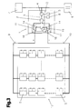
- FIG. 4 is a detailed schematic design of a photovoltaic unit with the theft recognition according to the invention in monitoring mode during a theft of a solar module.
- FIG. 1 illustrates the design of an inverter 1 , more particularly an HF inverter.
- inverter 1 more particularly an HF inverter.
- the inverter 1 includes at least one input DC-DC converter 2 , an intermediate circuit 3 and an output DC-AC converter 4 .
- the input DC-DC converter 2 is connected to an energy source 13 and/or an energy generator, which is preferably composed of one or more solar modules 5 that are connected in parallel and/or in series (see FIGS. 2-4 ).
- the inverter 1 and the solar modules 5 are referred to as photovoltaic unit and/or PV unit as well.
- the output of the inverter 1 and/or the output DC-AC converter 4 can be connected to a supply network 6 , such as a public or private AC voltage network or a multiple phase network, and/or at least one electric consumer 7 , which constitutes a load.
- a consumer 7 may be, for example, a motor, refrigerator, radio equipment etc.
- the consumer 7 may also constitute a home power supply system.
- the individual components of the inverter 1 such as the input DC-DC converter 2 etc., can be connected to a control device 8 by a data bus 12 .
- such an inverter 1 serves as a grid-connected inverter 1 , the energy management of which is optimised for feeding the supply network 6 with as much energy as possible.
- the consumers 7 are fed energy by the supply network 6 .
- a plurality of inverters 1 that are connected in parallel may be used as well. Thereby, more energy for operating the consumers 7 can be provided.
- the control device 8 and/or the controller of the inverter 1 is constituted, for example, by a micro processor, micro controller or computer.
- the control device 8 can be used for an appropriate control of the individual components of the inverter 1 , such as the input DC-DC converter 2 or the output DC-AC converter 4 , especially the circuit elements arranged therein.
- the individual control procedures for this are stored in the control device 8 by corresponding software programmes and/or data or characteristics.
- the energy source 13 is connected to the inverter 1 by two connector lines 9 , 10 and provides a suitable DC voltage.
- these two connector lines 9 , 10 are used to send an electric signal through the energy source 13 and/or the solar modules 5 .
- the energy source 13 and/or the solar modules 5 which are connected to the inverter 1 , form an electric circuit, the signal sent by the inverter 1 will be received again.
- an analysis of the signal sent by the inverter 1 can reveal whether the energy source 13 and/or a solar module 5 has been removed or stolen.
- Such a theft recognition is carried out only when the solar modules 5 do not provide a sufficiently high DC voltage for the inverter 1 to correspondingly convert to an AC voltage that the network can use. In this case, the inverter 1 does not feed AC to the supply network 6 any more. Thus, the inverter 1 starts or activates the theft recognition at night and/or at dusk.
- FIGS. 2 to 4 The method for the recognition of the theft of a solar module 5 according to the invention, involving the inverter 1 according to the invention, is illustrated in the following FIGS. 2 to 4 .
- a switchover device 11 according to the invention is provided in the inverter 1 for theft recognition.
- the connector lines 9 , 10 are connected to the DC-DC converter 2 by the switchover device, as illustrated in FIG. 2 .
- the switchover device 11 disconnects the inverter 1 from the solar modules 5 in order to activate the theft recognition according to the invention, as illustrated in FIG. 3 .
- the connector lines 9 , 10 are disconnected from the input DC-DC converter 2 of the inverter 1 , for example, by two switchover means 16 , 17 .
- the connection between the solar modules 5 and the inverter 1 is interrupted and the input capacitor of the inverter 1 , in particular, is disconnected, so it cannot be destroyed by the electric signal for theft recognition.
- the connector lines 9 , 10 for the energy source 13 and/or the solar modules 5 are connected to a signal unit 19 via connection lines 14 by the switchover device 11 and/or the switchover means 16 , 17 , as illustrated in FIG. 3 .
- this interruption is triggered by a starting signal which is, for example, transmitted from the control device 8 of the inverter 1 to a control unit 18 of the switchover device 11 via the data bus 12 . Then the control unit 18 will cause the activation of the switchover means 16 , 17 .
- switchover device 11 may include only one switchover means, in which case only the voltage loss of one switchover means has to be considered.
- Semiconductors, relays or similar members could, for example, be used as switchover means 16 , 17 .
- both inverters 1 are disconnected from the solar modules 5 by their respective integrated switchover device 11 in order to activate theft recognition.
- the inverters 1 are connected by a data bus 12 , so the disconnection of the inverters 1 occurs basically simultaneously.
- information about at which time which inverter 1 sends the electric signal for theft recognition and/or which of the inverters 1 performs this function is exchanged preferably via the data bus 12 . This guarantees that only one electric signal for theft recognition is sent at all and, thus, is not subject to interference.
- the inverter 1 has been disconnected from the solar modules 5 , so the method for theft recognition according to the invention can be carried out.
- an electric signal which has been generated in the signal unit 19 , is sent to the solar modules 5 via the connection lines 14 and the connector lines 9 , 10 to verify the presence of all solar modules 5 .
- the signal unit 19 may be integrated in or connected to the control unit 18 of the switchover device 11 , and may, for example, be constituted by a signal generator.
- the signal unit 19 can generate different electric signals, which mainly differ from each other in their signal forms and amplitudes. Consequently, the theft recognition, which is dependent on the signal, is not restricted to certain types of solar modules 5 .
- Corresponding data for different types of solar modules 5 may, for example, be stored in a memory of the control unit 18 , so the signal unit 19 can use it to generate a correspondingly suitable electric signal.
- the signal unit 19 has to know the type of the solar modules 5 . This can be detected by a number of procedures.
- the type of the solar modules 5 can be set in the inverter 1 and/or the control device 8 , or in the switchover device 11 and/or the control unit 18 when the PV unit is brought into operation.
- the signal unit 19 generates a corresponding electric signal for carrying out the theft recognition by using the stored data.
- the signal forms described hereinafter are eventually generated for theft recognition by the signal unit 19 , said signal forms being appropriately adjusted to the type of the solar modules 5 .
- the signal form may be formed by a DC voltage signal or an AC voltage signal with different amplitudes.
- a DC voltage with a constant amplitude may be used as a signal form for a certain type of solar modules 5 .
- the DC voltage causes a corresponding current to flow through the solar modules 5 .
- This signal form is suitable for solar modules 5 with integrated diodes, which only allow forward current in accordance with the diodes. By measuring and analysing the current that reaches the switchover device 11 and/or the signal unit 19 , a theft can be recognised.
- An AC voltage signal with a certain frequency (high frequency, in particular) and a constant amplitude may also be used as a signal form.
- the generated signal is transmitted to the solar module 5 via the connection line 14 , the transmission line and the corresponding connector line 9 , 10 , and received again via the other connector line 10 , 9 and the other connection line 14 , which serves as a reception line.
- This signal form is preferably used for solar modules 5 that do not have diodes and thus allow current flow in both directions.
- the switchover device 11 decides which direction is used as current flow for theft recognition on the basis of the received signal form, so a theft is recognised correctly. Consequently, the current can again flow through the solar modules 5 to be measured and/or analysed by the switchover device 11 and/or the signal unit 19 .
- Such an AC voltage signal may also be applied between one of the connector lines 9 , 10 and “ground”. Accordingly, an AC voltage signal with a suitable amplitude, such as 20 volt, is applied to one of the connector lines 9 , 10 , so part of this AC voltage is applied between an earthed mounting of the solar modules 5 and “ground”.
- the mounting and the solar modules 5 constitute a capacitance, so the part of the AC voltage and/or the current resulting from it is referred to as capacitive current.
- This capacitive current can be measured between one of the connector lines 9 , 10 and “groung” of the switchover device 11 , requiring the switchover device 11 to be earthed. Any change in this capacitive current might indicate a theft.
- the form of the signal received is changed by the capacitance, a theft of the solar modules 5 can also be detected in a difference between the received signal and the sent signal.
- the AC voltage signal is applied between the connector lines 9 , 10 .
- the electric signal will divide itself substantially evenly between the strings connected in parallel.
- the switchover device 11 and/or the signal unit 19 receive the total of all strings' currents.
- this signal form and the form of the signal that is normally (i. e. when all solar modules are present) received are being stored and a kind of calibration is carried out.
- the signal forms stored will serve as reference values and/or values for comparisons for at least the following night, so if the form of the received signals should deviate from the reference value, a theft is reliably detected.
- a change and/or deviation of the received signal form from the sent signal form is mainly detected by recognising a change in the current through the solar modules 5 , as its resistance changes because of missing solar modules 5 .
- the change that occurs is substantially sudden, as theft of one or more solar modules 5 from the circuit causes the resistance to undergo a substantially sudden change as well.
- more than one solar module 5 are removed at the same time, as preferably a number of solar modules 5 are connected in series to form what is known as a string. Now, if at least one solar module 5 of a string is removed, this will lead to a change in the resistance of the entire energy source 13 due to removing the resistance of one string.
- an alarm signal which can be transmitted to a data communication unit 15 of the inverter 1 via the data bus 12 , can be generated.
- the data communication unit 15 can produce an alarm message, which is communicated to defined persons and/or institutions by telephone, fax, e-mail or the like, or it can activate a warning light, signal horn or the like in the vicinity of the PV unit and/or a control centre. That way, a theft can be detected early and, as the case may be, prevented.
- the inverter 1 can be switched back to normal mode according to FIG. 2 .
- This switching is again done by the switchover device 11 , which monitors the voltage transferred by the solar modules 5 .
- the switchover means 16 , 17 are being switched over, so the connector lines 9 , 10 are being connected to the input DC-DC converter 2 .
- a corresponding signal is transmitted from the control unit 18 of the switchover device 11 to the control device 8 of the inverter 1 via the data bus 12 , so preferably the relevant hardware and software components can be activated.
- the inverter 1 can thus return to feeding energy to the supply network 6 and/or supplying the consumers 7 with energy.
- the inverter 1 receives electric energy from the supply network 6 or an energy storage.
- the electric signal can be sent in periodical intervals of time such as every second, every ten seconds or the like. Such an energy-saving measure will make it possible to maintain a substantially permanent theft recognition nevertheless.
- the theft recognition according to the invention is not dependent on the type of the inverter 1 .
- an inverter 1 with a 50 Hz transformer may be equipped with the device for recognising the theft of the energy source 13 and/or a solar module 5 .
Landscapes
- Engineering & Computer Science (AREA)
- Physics & Mathematics (AREA)
- Power Engineering (AREA)
- General Physics & Mathematics (AREA)
- Electromagnetism (AREA)
- Condensed Matter Physics & Semiconductors (AREA)
- Life Sciences & Earth Sciences (AREA)
- Sustainable Energy (AREA)
- Computer Hardware Design (AREA)
- Microelectronics & Electronic Packaging (AREA)
- Sustainable Development (AREA)
- Burglar Alarm Systems (AREA)
- Photovoltaic Devices (AREA)
Abstract
Description
Claims (20)
Applications Claiming Priority (4)
| Application Number | Priority Date | Filing Date | Title |
|---|---|---|---|
| ATA1350/2007A AT505731B1 (en) | 2007-08-29 | 2007-08-29 | METHOD FOR THE ALARM DETECTION OF A PHOTOVOLTAIC SYSTEM AND INVERTERS FOR A PHOTOVOLTAIC SYSTEM |
| ATA1350/2007 | 2007-08-29 | ||
| AT1350/2007 | 2007-08-29 | ||
| PCT/AT2008/000301 WO2009026602A1 (en) | 2007-08-29 | 2008-08-26 | Method for theft recognition on a photovoltaic unit and inverter for a photovoltaic unit |
Publications (2)
| Publication Number | Publication Date |
|---|---|
| US20100207764A1 US20100207764A1 (en) | 2010-08-19 |
| US8466789B2 true US8466789B2 (en) | 2013-06-18 |
Family
ID=39970886
Family Applications (1)
| Application Number | Title | Priority Date | Filing Date |
|---|---|---|---|
| US12/733,391 Expired - Fee Related US8466789B2 (en) | 2007-08-29 | 2008-08-26 | Method for theft recognition on a photovoltaic unit and inverter for a photovoltaic unit |
Country Status (6)
| Country | Link |
|---|---|
| US (1) | US8466789B2 (en) |
| EP (1) | EP2183730B1 (en) |
| AT (1) | AT505731B1 (en) |
| DK (1) | DK2183730T3 (en) |
| ES (1) | ES2428383T3 (en) |
| WO (1) | WO2009026602A1 (en) |
Cited By (46)
| Publication number | Priority date | Publication date | Assignee | Title |
|---|---|---|---|---|
| US20120306515A1 (en) * | 2011-06-01 | 2012-12-06 | Enphase Energy, Inc. | Method and apparatus for grid impedance detection |
| US20150115984A1 (en) * | 2009-05-26 | 2015-04-30 | Solaredge Technologies, Ltd. | Theft Detection and Prevention in a Power Generation System |
| US9812984B2 (en) | 2012-01-30 | 2017-11-07 | Solaredge Technologies Ltd. | Maximizing power in a photovoltaic distributed power system |
| US9819178B2 (en) | 2013-03-15 | 2017-11-14 | Solaredge Technologies Ltd. | Bypass mechanism |
| US9831824B2 (en) | 2007-12-05 | 2017-11-28 | SolareEdge Technologies Ltd. | Current sensing on a MOSFET |
| US9853565B2 (en) | 2012-01-30 | 2017-12-26 | Solaredge Technologies Ltd. | Maximized power in a photovoltaic distributed power system |
| US9853490B2 (en) | 2006-12-06 | 2017-12-26 | Solaredge Technologies Ltd. | Distributed power system using direct current power sources |
| US9853538B2 (en) | 2007-12-04 | 2017-12-26 | Solaredge Technologies Ltd. | Distributed power harvesting systems using DC power sources |
| US9866098B2 (en) | 2011-01-12 | 2018-01-09 | Solaredge Technologies Ltd. | Serially connected inverters |
| US9876430B2 (en) | 2008-03-24 | 2018-01-23 | Solaredge Technologies Ltd. | Zero voltage switching |
| US9923516B2 (en) | 2012-01-30 | 2018-03-20 | Solaredge Technologies Ltd. | Photovoltaic panel circuitry |
| US9935458B2 (en) | 2010-12-09 | 2018-04-03 | Solaredge Technologies Ltd. | Disconnection of a string carrying direct current power |
| US9948233B2 (en) | 2006-12-06 | 2018-04-17 | Solaredge Technologies Ltd. | Distributed power harvesting systems using DC power sources |
| US9960731B2 (en) | 2006-12-06 | 2018-05-01 | Solaredge Technologies Ltd. | Pairing of components in a direct current distributed power generation system |
| US9966766B2 (en) | 2006-12-06 | 2018-05-08 | Solaredge Technologies Ltd. | Battery power delivery module |
| US10007288B2 (en) | 2012-03-05 | 2018-06-26 | Solaredge Technologies Ltd. | Direct current link circuit |
| US10097007B2 (en) | 2006-12-06 | 2018-10-09 | Solaredge Technologies Ltd. | Method for distributed power harvesting using DC power sources |
| US10115841B2 (en) | 2012-06-04 | 2018-10-30 | Solaredge Technologies Ltd. | Integrated photovoltaic panel circuitry |
| US10116217B2 (en) | 2007-08-06 | 2018-10-30 | Solaredge Technologies Ltd. | Digital average input current control in power converter |
| US10230310B2 (en) | 2016-04-05 | 2019-03-12 | Solaredge Technologies Ltd | Safety switch for photovoltaic systems |
| US10396662B2 (en) | 2011-09-12 | 2019-08-27 | Solaredge Technologies Ltd | Direct current link circuit |
| US10461687B2 (en) | 2008-12-04 | 2019-10-29 | Solaredge Technologies Ltd. | Testing of a photovoltaic panel |
| US10468878B2 (en) | 2008-05-05 | 2019-11-05 | Solaredge Technologies Ltd. | Direct current power combiner |
| US10637393B2 (en) | 2006-12-06 | 2020-04-28 | Solaredge Technologies Ltd. | Distributed power harvesting systems using DC power sources |
| US10673222B2 (en) | 2010-11-09 | 2020-06-02 | Solaredge Technologies Ltd. | Arc detection and prevention in a power generation system |
| US10673229B2 (en) | 2010-11-09 | 2020-06-02 | Solaredge Technologies Ltd. | Arc detection and prevention in a power generation system |
| US10778025B2 (en) | 2013-03-14 | 2020-09-15 | Solaredge Technologies Ltd. | Method and apparatus for storing and depleting energy |
| US10931228B2 (en) | 2010-11-09 | 2021-02-23 | Solaredge Technologies Ftd. | Arc detection and prevention in a power generation system |
| US10931119B2 (en) | 2012-01-11 | 2021-02-23 | Solaredge Technologies Ltd. | Photovoltaic module |
| US11018623B2 (en) | 2016-04-05 | 2021-05-25 | Solaredge Technologies Ltd. | Safety switch for photovoltaic systems |
| US11031861B2 (en) | 2006-12-06 | 2021-06-08 | Solaredge Technologies Ltd. | System and method for protection during inverter shutdown in distributed power installations |
| US11177663B2 (en) | 2016-04-05 | 2021-11-16 | Solaredge Technologies Ltd. | Chain of power devices |
| US11264947B2 (en) | 2007-12-05 | 2022-03-01 | Solaredge Technologies Ltd. | Testing of a photovoltaic panel |
| US11296650B2 (en) | 2006-12-06 | 2022-04-05 | Solaredge Technologies Ltd. | System and method for protection during inverter shutdown in distributed power installations |
| US11309832B2 (en) | 2006-12-06 | 2022-04-19 | Solaredge Technologies Ltd. | Distributed power harvesting systems using DC power sources |
| US11569660B2 (en) | 2006-12-06 | 2023-01-31 | Solaredge Technologies Ltd. | Distributed power harvesting systems using DC power sources |
| US11569659B2 (en) | 2006-12-06 | 2023-01-31 | Solaredge Technologies Ltd. | Distributed power harvesting systems using DC power sources |
| US11579235B2 (en) | 2006-12-06 | 2023-02-14 | Solaredge Technologies Ltd. | Safety mechanisms, wake up and shutdown methods in distributed power installations |
| US11598652B2 (en) | 2006-12-06 | 2023-03-07 | Solaredge Technologies Ltd. | Monitoring of distributed power harvesting systems using DC power sources |
| US11687112B2 (en) | 2006-12-06 | 2023-06-27 | Solaredge Technologies Ltd. | Distributed power harvesting systems using DC power sources |
| US11728768B2 (en) | 2006-12-06 | 2023-08-15 | Solaredge Technologies Ltd. | Pairing of components in a direct current distributed power generation system |
| US11735910B2 (en) | 2006-12-06 | 2023-08-22 | Solaredge Technologies Ltd. | Distributed power system using direct current power sources |
| US11855231B2 (en) | 2006-12-06 | 2023-12-26 | Solaredge Technologies Ltd. | Distributed power harvesting systems using DC power sources |
| US11881814B2 (en) | 2005-12-05 | 2024-01-23 | Solaredge Technologies Ltd. | Testing of a photovoltaic panel |
| US11888387B2 (en) | 2006-12-06 | 2024-01-30 | Solaredge Technologies Ltd. | Safety mechanisms, wake up and shutdown methods in distributed power installations |
| US11996488B2 (en) | 2010-12-09 | 2024-05-28 | Solaredge Technologies Ltd. | Disconnection of a string carrying direct current power |
Families Citing this family (29)
| Publication number | Priority date | Publication date | Assignee | Title |
|---|---|---|---|---|
| US9291696B2 (en) | 2007-12-05 | 2016-03-22 | Solaredge Technologies Ltd. | Photovoltaic system power tracking method |
| US8289742B2 (en) | 2007-12-05 | 2012-10-16 | Solaredge Ltd. | Parallel connected inverters |
| IT1394581B1 (en) * | 2009-06-23 | 2012-07-05 | Fast Spa | MEASUREMENT EQUIPMENT FOR VOLTAGE AND CURRENT GENERATED BY PHOTOVOLTAIC PANELS |
| EP2454795A4 (en) | 2009-07-14 | 2016-09-21 | Enphase Energy Inc | Method and apparatus for identifying redeployed distributed generator components |
| US8773236B2 (en) * | 2009-12-29 | 2014-07-08 | Tigo Energy, Inc. | Systems and methods for a communication protocol between a local controller and a master controller |
| US8271599B2 (en) | 2010-01-08 | 2012-09-18 | Tigo Energy, Inc. | Systems and methods for an identification protocol between a local controller and a master controller in a photovoltaic power generation system |
| US8907614B2 (en) * | 2010-03-25 | 2014-12-09 | Honda Motor Co., Ltd. | Photovoltaic power generation system |
| WO2011130733A1 (en) | 2010-04-16 | 2011-10-20 | Enphase Energy, Inc. | Method and apparatus for indicating a disconnection within a distributed generator |
| US9007210B2 (en) * | 2010-04-22 | 2015-04-14 | Tigo Energy, Inc. | Enhanced system and method for theft prevention in a solar power array during nonoperative periods |
| CN102918571B (en) * | 2010-05-31 | 2015-04-01 | 太阳能安吉科技有限公司 | Theft detection and prevention in a power generation system |
| CN103026248B (en) * | 2010-06-28 | 2015-09-02 | Sma太阳能技术股份公司 | For monitoring the apparatus and method of photovoltaic apparatus |
| DE102010036816A1 (en) * | 2010-08-03 | 2012-02-09 | Newtos Ag | Method and device for monitoring and controlling a photovoltaic system |
| US10615743B2 (en) | 2010-08-24 | 2020-04-07 | David Crites | Active and passive monitoring system for installed photovoltaic strings, substrings, and modules |
| DE202011110600U1 (en) | 2011-09-14 | 2015-02-05 | Solar Bavaria Bayern Süd GmbH | Device for monitoring critical temperature developments on solar systems with photovoltaic modules |
| GB2495939A (en) * | 2011-10-25 | 2013-05-01 | Lowes Stewart Developments Ltd | Solar panel alarm system |
| ITPD20110401A1 (en) * | 2011-12-20 | 2013-06-21 | Elettrograf S R L | ANTI-THEFT DEVICE FOR ELECTRIC CABLES |
| ITPD20110419A1 (en) * | 2011-12-30 | 2013-07-01 | Convert Italia Spa | METHOD AND DEVICE FOR THE DETECTION OF TAMPERING OR THEFT OF A COMPONENT OF AN ELECTRIC CIRCUIT |
| EP2631952B1 (en) * | 2012-02-24 | 2018-09-19 | VTQ Videotronik GmbH | Method and apparatus for the functional and disassembly detection of solar modules |
| WO2013130563A1 (en) * | 2012-02-27 | 2013-09-06 | Tigo Energy, Inc. | Anti-theft system and method for large solar panel systems |
| US9941813B2 (en) | 2013-03-14 | 2018-04-10 | Solaredge Technologies Ltd. | High frequency multi-level inverter |
| KR101484699B1 (en) | 2013-05-13 | 2015-01-20 | 최범진 | Battery Module Capable of Preventing Theft or Correlation Control for Street Light of Solar Cell in a Single |
| ITRM20130412A1 (en) * | 2013-07-12 | 2015-01-13 | Enersis S R L En E Sistemi | SYSTEM WITH ANTI-THEFT SYSTEM FOR ELECTRIC CABLES. |
| US9318974B2 (en) | 2014-03-26 | 2016-04-19 | Solaredge Technologies Ltd. | Multi-level inverter with flying capacitor topology |
| US9496230B1 (en) * | 2015-04-30 | 2016-11-15 | International Business Machines Corporation | Light sensitive switch for semiconductor package tamper detection |
| CN107153212B (en) | 2016-03-03 | 2023-07-28 | 太阳能安吉科技有限公司 | Method for mapping a power generation facility |
| US10599113B2 (en) | 2016-03-03 | 2020-03-24 | Solaredge Technologies Ltd. | Apparatus and method for determining an order of power devices in power generation systems |
| US11081608B2 (en) | 2016-03-03 | 2021-08-03 | Solaredge Technologies Ltd. | Apparatus and method for determining an order of power devices in power generation systems |
| CN106980063B (en) * | 2017-05-05 | 2020-03-13 | 华为技术有限公司 | Monitoring method of power generation equipment and inverter |
| CN113131863B (en) * | 2019-12-31 | 2023-03-28 | 华为数字能源技术有限公司 | Photovoltaic system, photovoltaic module and anti-theft method thereof |
Citations (13)
| Publication number | Priority date | Publication date | Assignee | Title |
|---|---|---|---|---|
| US4121201A (en) * | 1974-03-22 | 1978-10-17 | Bunker Ramo Corporation | Carrier current appliance theft alarm |
| EP0584540A1 (en) | 1992-07-27 | 1994-03-02 | Transec S.A. | Device for monitoring the connection of an electric apparatus with a power source |
| DE9411783U1 (en) | 1994-07-21 | 1995-02-02 | Helix Solarelektronik Gmbh | Theft protection for photovoltaic solar generators |
| GB2286475A (en) | 1994-02-09 | 1995-08-16 | Winston Paul Rose | Theft alarm system |
| JP2000164906A (en) | 1998-11-26 | 2000-06-16 | Fujitsu Denso Ltd | Theft detection circuit for solar battery and solar battery distribution panel |
| US20020063625A1 (en) | 2000-10-30 | 2002-05-30 | Nobuyoshi Takehara | Power converter apparatus and burglarproof method therefor |
| DE10136147A1 (en) | 2001-07-25 | 2003-02-20 | Hendrik Kolm | Photovoltaic alternating current generator has solar modules, each electrically connected to individual D.C. voltage converter that transforms to intermediate D.C. voltage and decouples module |
| DE10161480A1 (en) | 2001-12-14 | 2003-07-03 | Saint Gobain | Operating photovoltaic solar module, involves triggering alarm signal on detecting resistance for series circuit above threshold or measurement current attenuation to below desired level |
| US20040216777A1 (en) * | 2003-04-30 | 2004-11-04 | Jin-Huang Pan | Solar tracking storage system and method |
| WO2007048421A2 (en) | 2005-10-24 | 2007-05-03 | Conergy Ag | Switch-fuse with control management for solar cells |
| WO2008043814A1 (en) | 2006-10-13 | 2008-04-17 | Elettronica Santerno S.P.A. | Solar inverter and plant for converting solar energy into electrical energy |
| WO2008046370A1 (en) | 2006-10-19 | 2008-04-24 | Fpe Fischer Gmbh | Method and circuit for monitoring a solar panel for theft |
| US7772974B2 (en) * | 2005-02-28 | 2010-08-10 | Cypak Ab | Tamper evident seal system and method |
-
2007
- 2007-08-29 AT ATA1350/2007A patent/AT505731B1/en not_active IP Right Cessation
-
2008
- 2008-08-26 DK DK08782829.9T patent/DK2183730T3/en active
- 2008-08-26 EP EP08782829.9A patent/EP2183730B1/en not_active Not-in-force
- 2008-08-26 US US12/733,391 patent/US8466789B2/en not_active Expired - Fee Related
- 2008-08-26 ES ES08782829T patent/ES2428383T3/en active Active
- 2008-08-26 WO PCT/AT2008/000301 patent/WO2009026602A1/en active Application Filing
Patent Citations (13)
| Publication number | Priority date | Publication date | Assignee | Title |
|---|---|---|---|---|
| US4121201A (en) * | 1974-03-22 | 1978-10-17 | Bunker Ramo Corporation | Carrier current appliance theft alarm |
| EP0584540A1 (en) | 1992-07-27 | 1994-03-02 | Transec S.A. | Device for monitoring the connection of an electric apparatus with a power source |
| GB2286475A (en) | 1994-02-09 | 1995-08-16 | Winston Paul Rose | Theft alarm system |
| DE9411783U1 (en) | 1994-07-21 | 1995-02-02 | Helix Solarelektronik Gmbh | Theft protection for photovoltaic solar generators |
| JP2000164906A (en) | 1998-11-26 | 2000-06-16 | Fujitsu Denso Ltd | Theft detection circuit for solar battery and solar battery distribution panel |
| US20020063625A1 (en) | 2000-10-30 | 2002-05-30 | Nobuyoshi Takehara | Power converter apparatus and burglarproof method therefor |
| DE10136147A1 (en) | 2001-07-25 | 2003-02-20 | Hendrik Kolm | Photovoltaic alternating current generator has solar modules, each electrically connected to individual D.C. voltage converter that transforms to intermediate D.C. voltage and decouples module |
| DE10161480A1 (en) | 2001-12-14 | 2003-07-03 | Saint Gobain | Operating photovoltaic solar module, involves triggering alarm signal on detecting resistance for series circuit above threshold or measurement current attenuation to below desired level |
| US20040216777A1 (en) * | 2003-04-30 | 2004-11-04 | Jin-Huang Pan | Solar tracking storage system and method |
| US7772974B2 (en) * | 2005-02-28 | 2010-08-10 | Cypak Ab | Tamper evident seal system and method |
| WO2007048421A2 (en) | 2005-10-24 | 2007-05-03 | Conergy Ag | Switch-fuse with control management for solar cells |
| WO2008043814A1 (en) | 2006-10-13 | 2008-04-17 | Elettronica Santerno S.P.A. | Solar inverter and plant for converting solar energy into electrical energy |
| WO2008046370A1 (en) | 2006-10-19 | 2008-04-24 | Fpe Fischer Gmbh | Method and circuit for monitoring a solar panel for theft |
Non-Patent Citations (3)
| Title |
|---|
| Austrian Office Action dated May 30, 2008 with English translation of relevant parts. |
| European Search Report dated Sep. 26, 2012 in the corresponding European Patent Application 08782829.9 with an English translation of relevant parts. |
| International Search Report. |
Cited By (93)
| Publication number | Priority date | Publication date | Assignee | Title |
|---|---|---|---|---|
| US11881814B2 (en) | 2005-12-05 | 2024-01-23 | Solaredge Technologies Ltd. | Testing of a photovoltaic panel |
| US11579235B2 (en) | 2006-12-06 | 2023-02-14 | Solaredge Technologies Ltd. | Safety mechanisms, wake up and shutdown methods in distributed power installations |
| US11575261B2 (en) | 2006-12-06 | 2023-02-07 | Solaredge Technologies Ltd. | Distributed power harvesting systems using DC power sources |
| US11961922B2 (en) | 2006-12-06 | 2024-04-16 | Solaredge Technologies Ltd. | Distributed power harvesting systems using DC power sources |
| US11962243B2 (en) | 2006-12-06 | 2024-04-16 | Solaredge Technologies Ltd. | Method for distributed power harvesting using DC power sources |
| US11888387B2 (en) | 2006-12-06 | 2024-01-30 | Solaredge Technologies Ltd. | Safety mechanisms, wake up and shutdown methods in distributed power installations |
| US11855231B2 (en) | 2006-12-06 | 2023-12-26 | Solaredge Technologies Ltd. | Distributed power harvesting systems using DC power sources |
| US9853490B2 (en) | 2006-12-06 | 2017-12-26 | Solaredge Technologies Ltd. | Distributed power system using direct current power sources |
| US11735910B2 (en) | 2006-12-06 | 2023-08-22 | Solaredge Technologies Ltd. | Distributed power system using direct current power sources |
| US11728768B2 (en) | 2006-12-06 | 2023-08-15 | Solaredge Technologies Ltd. | Pairing of components in a direct current distributed power generation system |
| US11687112B2 (en) | 2006-12-06 | 2023-06-27 | Solaredge Technologies Ltd. | Distributed power harvesting systems using DC power sources |
| US11682918B2 (en) | 2006-12-06 | 2023-06-20 | Solaredge Technologies Ltd. | Battery power delivery module |
| US11658482B2 (en) | 2006-12-06 | 2023-05-23 | Solaredge Technologies Ltd. | Distributed power harvesting systems using DC power sources |
| US11598652B2 (en) | 2006-12-06 | 2023-03-07 | Solaredge Technologies Ltd. | Monitoring of distributed power harvesting systems using DC power sources |
| US9948233B2 (en) | 2006-12-06 | 2018-04-17 | Solaredge Technologies Ltd. | Distributed power harvesting systems using DC power sources |
| US9960731B2 (en) | 2006-12-06 | 2018-05-01 | Solaredge Technologies Ltd. | Pairing of components in a direct current distributed power generation system |
| US11594881B2 (en) | 2006-12-06 | 2023-02-28 | Solaredge Technologies Ltd. | Distributed power harvesting systems using DC power sources |
| US11594882B2 (en) | 2006-12-06 | 2023-02-28 | Solaredge Technologies Ltd. | Distributed power harvesting systems using DC power sources |
| US11594880B2 (en) | 2006-12-06 | 2023-02-28 | Solaredge Technologies Ltd. | Distributed power harvesting systems using DC power sources |
| US10097007B2 (en) | 2006-12-06 | 2018-10-09 | Solaredge Technologies Ltd. | Method for distributed power harvesting using DC power sources |
| US11575260B2 (en) | 2006-12-06 | 2023-02-07 | Solaredge Technologies Ltd. | Distributed power harvesting systems using DC power sources |
| US11569659B2 (en) | 2006-12-06 | 2023-01-31 | Solaredge Technologies Ltd. | Distributed power harvesting systems using DC power sources |
| US11063440B2 (en) | 2006-12-06 | 2021-07-13 | Solaredge Technologies Ltd. | Method for distributed power harvesting using DC power sources |
| US11569660B2 (en) | 2006-12-06 | 2023-01-31 | Solaredge Technologies Ltd. | Distributed power harvesting systems using DC power sources |
| US11476799B2 (en) | 2006-12-06 | 2022-10-18 | Solaredge Technologies Ltd. | Distributed power harvesting systems using DC power sources |
| US11309832B2 (en) | 2006-12-06 | 2022-04-19 | Solaredge Technologies Ltd. | Distributed power harvesting systems using DC power sources |
| US10447150B2 (en) | 2006-12-06 | 2019-10-15 | Solaredge Technologies Ltd. | Distributed power harvesting systems using DC power sources |
| US11296650B2 (en) | 2006-12-06 | 2022-04-05 | Solaredge Technologies Ltd. | System and method for protection during inverter shutdown in distributed power installations |
| US11183922B2 (en) | 2006-12-06 | 2021-11-23 | Solaredge Technologies Ltd. | Distributed power harvesting systems using DC power sources |
| US9966766B2 (en) | 2006-12-06 | 2018-05-08 | Solaredge Technologies Ltd. | Battery power delivery module |
| US10230245B2 (en) | 2006-12-06 | 2019-03-12 | Solaredge Technologies Ltd | Battery power delivery module |
| US10637393B2 (en) | 2006-12-06 | 2020-04-28 | Solaredge Technologies Ltd. | Distributed power harvesting systems using DC power sources |
| US11043820B2 (en) | 2006-12-06 | 2021-06-22 | Solaredge Technologies Ltd. | Battery power delivery module |
| US11031861B2 (en) | 2006-12-06 | 2021-06-08 | Solaredge Technologies Ltd. | System and method for protection during inverter shutdown in distributed power installations |
| US10673253B2 (en) | 2006-12-06 | 2020-06-02 | Solaredge Technologies Ltd. | Battery power delivery module |
| US11594968B2 (en) | 2007-08-06 | 2023-02-28 | Solaredge Technologies Ltd. | Digital average input current control in power converter |
| US10516336B2 (en) | 2007-08-06 | 2019-12-24 | Solaredge Technologies Ltd. | Digital average input current control in power converter |
| US10116217B2 (en) | 2007-08-06 | 2018-10-30 | Solaredge Technologies Ltd. | Digital average input current control in power converter |
| US9853538B2 (en) | 2007-12-04 | 2017-12-26 | Solaredge Technologies Ltd. | Distributed power harvesting systems using DC power sources |
| US10644589B2 (en) | 2007-12-05 | 2020-05-05 | Solaredge Technologies Ltd. | Parallel connected inverters |
| US11693080B2 (en) | 2007-12-05 | 2023-07-04 | Solaredge Technologies Ltd. | Parallel connected inverters |
| US11183923B2 (en) | 2007-12-05 | 2021-11-23 | Solaredge Technologies Ltd. | Parallel connected inverters |
| US9831824B2 (en) | 2007-12-05 | 2017-11-28 | SolareEdge Technologies Ltd. | Current sensing on a MOSFET |
| US11183969B2 (en) | 2007-12-05 | 2021-11-23 | Solaredge Technologies Ltd. | Testing of a photovoltaic panel |
| US11894806B2 (en) | 2007-12-05 | 2024-02-06 | Solaredge Technologies Ltd. | Testing of a photovoltaic panel |
| US11264947B2 (en) | 2007-12-05 | 2022-03-01 | Solaredge Technologies Ltd. | Testing of a photovoltaic panel |
| US9979280B2 (en) | 2007-12-05 | 2018-05-22 | Solaredge Technologies Ltd. | Parallel connected inverters |
| US9876430B2 (en) | 2008-03-24 | 2018-01-23 | Solaredge Technologies Ltd. | Zero voltage switching |
| US11424616B2 (en) | 2008-05-05 | 2022-08-23 | Solaredge Technologies Ltd. | Direct current power combiner |
| US10468878B2 (en) | 2008-05-05 | 2019-11-05 | Solaredge Technologies Ltd. | Direct current power combiner |
| US10461687B2 (en) | 2008-12-04 | 2019-10-29 | Solaredge Technologies Ltd. | Testing of a photovoltaic panel |
| US20150115984A1 (en) * | 2009-05-26 | 2015-04-30 | Solaredge Technologies, Ltd. | Theft Detection and Prevention in a Power Generation System |
| US11867729B2 (en) | 2009-05-26 | 2024-01-09 | Solaredge Technologies Ltd. | Theft detection and prevention in a power generation system |
| US9869701B2 (en) * | 2009-05-26 | 2018-01-16 | Solaredge Technologies Ltd. | Theft detection and prevention in a power generation system |
| US10969412B2 (en) | 2009-05-26 | 2021-04-06 | Solaredge Technologies Ltd. | Theft detection and prevention in a power generation system |
| US11489330B2 (en) | 2010-11-09 | 2022-11-01 | Solaredge Technologies Ltd. | Arc detection and prevention in a power generation system |
| US11070051B2 (en) | 2010-11-09 | 2021-07-20 | Solaredge Technologies Ltd. | Arc detection and prevention in a power generation system |
| US10673229B2 (en) | 2010-11-09 | 2020-06-02 | Solaredge Technologies Ltd. | Arc detection and prevention in a power generation system |
| US10673222B2 (en) | 2010-11-09 | 2020-06-02 | Solaredge Technologies Ltd. | Arc detection and prevention in a power generation system |
| US10931228B2 (en) | 2010-11-09 | 2021-02-23 | Solaredge Technologies Ftd. | Arc detection and prevention in a power generation system |
| US11349432B2 (en) | 2010-11-09 | 2022-05-31 | Solaredge Technologies Ltd. | Arc detection and prevention in a power generation system |
| US9935458B2 (en) | 2010-12-09 | 2018-04-03 | Solaredge Technologies Ltd. | Disconnection of a string carrying direct current power |
| US11996488B2 (en) | 2010-12-09 | 2024-05-28 | Solaredge Technologies Ltd. | Disconnection of a string carrying direct current power |
| US11271394B2 (en) | 2010-12-09 | 2022-03-08 | Solaredge Technologies Ltd. | Disconnection of a string carrying direct current power |
| US9866098B2 (en) | 2011-01-12 | 2018-01-09 | Solaredge Technologies Ltd. | Serially connected inverters |
| US11205946B2 (en) | 2011-01-12 | 2021-12-21 | Solaredge Technologies Ltd. | Serially connected inverters |
| US10666125B2 (en) | 2011-01-12 | 2020-05-26 | Solaredge Technologies Ltd. | Serially connected inverters |
| US8896330B2 (en) * | 2011-06-01 | 2014-11-25 | Enphase Energy, Inc. | Method and apparatus for grid impedance detection |
| US20120306515A1 (en) * | 2011-06-01 | 2012-12-06 | Enphase Energy, Inc. | Method and apparatus for grid impedance detection |
| US10396662B2 (en) | 2011-09-12 | 2019-08-27 | Solaredge Technologies Ltd | Direct current link circuit |
| US10931119B2 (en) | 2012-01-11 | 2021-02-23 | Solaredge Technologies Ltd. | Photovoltaic module |
| US11979037B2 (en) | 2012-01-11 | 2024-05-07 | Solaredge Technologies Ltd. | Photovoltaic module |
| US9853565B2 (en) | 2012-01-30 | 2017-12-26 | Solaredge Technologies Ltd. | Maximized power in a photovoltaic distributed power system |
| US11929620B2 (en) | 2012-01-30 | 2024-03-12 | Solaredge Technologies Ltd. | Maximizing power in a photovoltaic distributed power system |
| US10381977B2 (en) | 2012-01-30 | 2019-08-13 | Solaredge Technologies Ltd | Photovoltaic panel circuitry |
| US11620885B2 (en) | 2012-01-30 | 2023-04-04 | Solaredge Technologies Ltd. | Photovoltaic panel circuitry |
| US9923516B2 (en) | 2012-01-30 | 2018-03-20 | Solaredge Technologies Ltd. | Photovoltaic panel circuitry |
| US10992238B2 (en) | 2012-01-30 | 2021-04-27 | Solaredge Technologies Ltd. | Maximizing power in a photovoltaic distributed power system |
| US11183968B2 (en) | 2012-01-30 | 2021-11-23 | Solaredge Technologies Ltd. | Photovoltaic panel circuitry |
| US9812984B2 (en) | 2012-01-30 | 2017-11-07 | Solaredge Technologies Ltd. | Maximizing power in a photovoltaic distributed power system |
| US10608553B2 (en) | 2012-01-30 | 2020-03-31 | Solaredge Technologies Ltd. | Maximizing power in a photovoltaic distributed power system |
| US10007288B2 (en) | 2012-03-05 | 2018-06-26 | Solaredge Technologies Ltd. | Direct current link circuit |
| US11177768B2 (en) | 2012-06-04 | 2021-11-16 | Solaredge Technologies Ltd. | Integrated photovoltaic panel circuitry |
| US10115841B2 (en) | 2012-06-04 | 2018-10-30 | Solaredge Technologies Ltd. | Integrated photovoltaic panel circuitry |
| US10778025B2 (en) | 2013-03-14 | 2020-09-15 | Solaredge Technologies Ltd. | Method and apparatus for storing and depleting energy |
| US10651647B2 (en) | 2013-03-15 | 2020-05-12 | Solaredge Technologies Ltd. | Bypass mechanism |
| US9819178B2 (en) | 2013-03-15 | 2017-11-14 | Solaredge Technologies Ltd. | Bypass mechanism |
| US11424617B2 (en) | 2013-03-15 | 2022-08-23 | Solaredge Technologies Ltd. | Bypass mechanism |
| US11177663B2 (en) | 2016-04-05 | 2021-11-16 | Solaredge Technologies Ltd. | Chain of power devices |
| US11018623B2 (en) | 2016-04-05 | 2021-05-25 | Solaredge Technologies Ltd. | Safety switch for photovoltaic systems |
| US11870250B2 (en) | 2016-04-05 | 2024-01-09 | Solaredge Technologies Ltd. | Chain of power devices |
| US11201476B2 (en) | 2016-04-05 | 2021-12-14 | Solaredge Technologies Ltd. | Photovoltaic power device and wiring |
| US10230310B2 (en) | 2016-04-05 | 2019-03-12 | Solaredge Technologies Ltd | Safety switch for photovoltaic systems |
Also Published As
| Publication number | Publication date |
|---|---|
| EP2183730A1 (en) | 2010-05-12 |
| ES2428383T3 (en) | 2013-11-07 |
| AT505731B1 (en) | 2013-03-15 |
| DK2183730T3 (en) | 2013-11-04 |
| WO2009026602A1 (en) | 2009-03-05 |
| AT505731A1 (en) | 2009-03-15 |
| EP2183730B1 (en) | 2013-07-24 |
| US20100207764A1 (en) | 2010-08-19 |
Similar Documents
| Publication | Publication Date | Title |
|---|---|---|
| US8466789B2 (en) | Method for theft recognition on a photovoltaic unit and inverter for a photovoltaic unit | |
| US8461716B2 (en) | Photovoltaic power generating device, and controlling method | |
| US8749395B2 (en) | Method and apparatus for indicating a disconnection within a distributed generator | |
| US8659858B2 (en) | Ground-fault detecting device, current collecting box using the ground-fault detecting device, and photovoltaic power generating device using the current collecting box | |
| US20120050924A1 (en) | Current collecting box for photovoltaic power generation | |
| CN101523230B (en) | Solar inverter and plant for converting solar energy into electrical energy | |
| KR100918964B1 (en) | Apparatus for trouble detecting of solar cell module by dispersion sensing | |
| US20120049627A1 (en) | Current collecting box for photovoltaic power generation | |
| US20100295680A1 (en) | Anti-Theft Monitoring Device and a Method for Monitoring an Electrical Applicance, Especially a Solar Module | |
| EP2136411B1 (en) | Antitheft and monitoring system for photovoltaic panels | |
| JP2008500797A (en) | Photovoltaic installation having one or more solar inverters | |
| AU2011291132A1 (en) | Method for controlling individual photovoltaic modules in a photovoltaic installation, and control device | |
| KR101509536B1 (en) | Monitoring system for solar light generation | |
| KR101667914B1 (en) | Photovoltaics system having a function of foreknowledge failture intelligently | |
| KR101479285B1 (en) | Apparatus for detecting loose contact of solar power generation system junction box | |
| US10230325B2 (en) | Remote array mapping | |
| JP6611435B2 (en) | Abnormality detection system for photovoltaic power generation facilities | |
| KR20120086558A (en) | Solar power generation system with monitoring and neutral line replacement | |
| KR20170118393A (en) | Monitoring apparatus for solar power generation system using mppt | |
| KR20130005979A (en) | Management system for photovoltaic power generation system | |
| US10892708B2 (en) | Remote array mapping | |
| KR101030925B1 (en) | Solar power generation system with monitoring and neutral line replacement | |
| KR101603893B1 (en) | Connection Board of Photovoltaics System having Sensing Function for PV module | |
| EP2336992A2 (en) | Electronic control system for photovoltaic modules | |
| JP7270942B1 (en) | Anomaly detection system and anomaly detection method |
Legal Events
| Date | Code | Title | Description |
|---|---|---|---|
| AS | Assignment |
Owner name: FRONIUS INTERNATIONAL GMBH, AUSTRIA Free format text: ASSIGNMENT OF ASSIGNORS INTEREST;ASSIGNORS:MUEHLBERGER, THOMAS;PROETSCH, ROLAND;SIGNING DATES FROM 20100211 TO 20100212;REEL/FRAME:024156/0584 |
|
| STCF | Information on status: patent grant |
Free format text: PATENTED CASE |
|
| FPAY | Fee payment |
Year of fee payment: 4 |
|
| FEPP | Fee payment procedure |
Free format text: MAINTENANCE FEE REMINDER MAILED (ORIGINAL EVENT CODE: REM.); ENTITY STATUS OF PATENT OWNER: LARGE ENTITY |
|
| LAPS | Lapse for failure to pay maintenance fees |
Free format text: PATENT EXPIRED FOR FAILURE TO PAY MAINTENANCE FEES (ORIGINAL EVENT CODE: EXP.); ENTITY STATUS OF PATENT OWNER: LARGE ENTITY |
|
| STCH | Information on status: patent discontinuation |
Free format text: PATENT EXPIRED DUE TO NONPAYMENT OF MAINTENANCE FEES UNDER 37 CFR 1.362 |
|
| FP | Lapsed due to failure to pay maintenance fee |
Effective date: 20210618 |