US8207701B2 - Control method of electromotor - Google Patents
Control method of electromotor Download PDFInfo
- Publication number
- US8207701B2 US8207701B2 US12/447,429 US44742909A US8207701B2 US 8207701 B2 US8207701 B2 US 8207701B2 US 44742909 A US44742909 A US 44742909A US 8207701 B2 US8207701 B2 US 8207701B2
- Authority
- US
- United States
- Prior art keywords
- electromotor
- current
- angle
- rotor
- phase
- Prior art date
- Legal status (The legal status is an assumption and is not a legal conclusion. Google has not performed a legal analysis and makes no representation as to the accuracy of the status listed.)
- Active, expires
Links
- 238000000034 method Methods 0.000 title claims abstract description 49
- 238000006243 chemical reaction Methods 0.000 claims abstract description 26
- 230000033228 biological regulation Effects 0.000 claims description 25
- 230000010354 integration Effects 0.000 claims description 22
- 238000012937 correction Methods 0.000 claims description 12
- 238000005070 sampling Methods 0.000 claims description 9
- 230000001133 acceleration Effects 0.000 claims description 4
- 238000004804 winding Methods 0.000 description 13
- 230000003750 conditioning effect Effects 0.000 description 6
- 238000012545 processing Methods 0.000 description 5
- 238000004364 calculation method Methods 0.000 description 4
- 230000005284 excitation Effects 0.000 description 3
- 230000008569 process Effects 0.000 description 3
- 230000001105 regulatory effect Effects 0.000 description 3
- 238000012986 modification Methods 0.000 description 2
- 230000004048 modification Effects 0.000 description 2
- 230000001360 synchronised effect Effects 0.000 description 2
- 230000005540 biological transmission Effects 0.000 description 1
- 239000003990 capacitor Substances 0.000 description 1
- 230000008859 change Effects 0.000 description 1
- 230000001276 controlling effect Effects 0.000 description 1
- 238000005260 corrosion Methods 0.000 description 1
- 230000007797 corrosion Effects 0.000 description 1
- 230000008878 coupling Effects 0.000 description 1
- 238000010168 coupling process Methods 0.000 description 1
- 238000005859 coupling reaction Methods 0.000 description 1
- 230000003111 delayed effect Effects 0.000 description 1
- 238000001514 detection method Methods 0.000 description 1
- 238000010586 diagram Methods 0.000 description 1
- 230000000694 effects Effects 0.000 description 1
- 238000001914 filtration Methods 0.000 description 1
- 230000006698 induction Effects 0.000 description 1
- 230000007935 neutral effect Effects 0.000 description 1
- 230000010355 oscillation Effects 0.000 description 1
- 230000002035 prolonged effect Effects 0.000 description 1
- 230000002441 reversible effect Effects 0.000 description 1
- 230000003068 static effect Effects 0.000 description 1
- 238000012546 transfer Methods 0.000 description 1
- 230000009466 transformation Effects 0.000 description 1
Images


Classifications
-
- H—ELECTRICITY
- H02—GENERATION; CONVERSION OR DISTRIBUTION OF ELECTRIC POWER
- H02P—CONTROL OR REGULATION OF ELECTRIC MOTORS, ELECTRIC GENERATORS OR DYNAMO-ELECTRIC CONVERTERS; CONTROLLING TRANSFORMERS, REACTORS OR CHOKE COILS
- H02P29/00—Arrangements for regulating or controlling electric motors, appropriate for both AC and DC motors
- H02P29/0016—Control of angular speed of one shaft without controlling the prime mover
-
- G—PHYSICS
- G01—MEASURING; TESTING
- G01D—MEASURING NOT SPECIALLY ADAPTED FOR A SPECIFIC VARIABLE; ARRANGEMENTS FOR MEASURING TWO OR MORE VARIABLES NOT COVERED IN A SINGLE OTHER SUBCLASS; TARIFF METERING APPARATUS; MEASURING OR TESTING NOT OTHERWISE PROVIDED FOR
- G01D21/00—Measuring or testing not otherwise provided for
-
- G—PHYSICS
- G01—MEASURING; TESTING
- G01P—MEASURING LINEAR OR ANGULAR SPEED, ACCELERATION, DECELERATION, OR SHOCK; INDICATING PRESENCE, ABSENCE, OR DIRECTION, OF MOVEMENT
- G01P3/00—Measuring linear or angular speed; Measuring differences of linear or angular speeds
- G01P3/42—Devices characterised by the use of electric or magnetic means
- G01P3/44—Devices characterised by the use of electric or magnetic means for measuring angular speed
- G01P3/48—Devices characterised by the use of electric or magnetic means for measuring angular speed by measuring frequency of generated current or voltage
-
- H—ELECTRICITY
- H02—GENERATION; CONVERSION OR DISTRIBUTION OF ELECTRIC POWER
- H02P—CONTROL OR REGULATION OF ELECTRIC MOTORS, ELECTRIC GENERATORS OR DYNAMO-ELECTRIC CONVERTERS; CONTROLLING TRANSFORMERS, REACTORS OR CHOKE COILS
- H02P21/00—Arrangements or methods for the control of electric machines by vector control, e.g. by control of field orientation
- H02P21/22—Current control, e.g. using a current control loop
Definitions
- the present invention relates to a control method of the electromotor, more specifically, to a control method of the electromotor used in the electric vehicles.
- the existing control method of electromotor comprises the steps of: setting a target rotating velocity n ref of the electromotor rotor; detecting an actual rotating velocity n; inputting the difference between the target rotating velocity and the actual rotating velocity n to a velocity loop and performing PI regulation; outputting a required rotating velocity of the electromotor and detecting the rotor position of the electromotor to determine the angle of the rotor position; determining a required alternating axis current id′ based on the required rotating velocity output by PI regulation; determining a required direct axis voltage ud and the required alternating voltage uq based on the direct axis current iq′ calculated from the rotor angular velocity of the electromotor; and performing Clark and Park inverse conversions to the required direct axis voltage ud and the required alternating voltage uq according to the rotating velocity of the electromotor rotor; outputting three-phase voltages ua, ub and uc; calculating a duty ratio between pulse width modulation (PWM) control
- the existing electromotor control method controls the electromotor using velocity: first performing PI regulation to the rotating velocity of the electromotor rotor, then controlling the electromotor torque by regulating the alternating axis current of the electromotor. Accordingly, the responding is relatively slow.
- the present invention has been made in view of the above circumstance and provides an electromotor control method with faster responding.
- an electromotor control method comprises the steps of: setting a target alternating axis current iq* based on a target rotor angular velocity w* of the electromotor and setting a target direct axis current id* based on the torque of the electromotor; simultaneously detecting and collecting current three-phase currents ia, ib and ic of the electromotor and current rotor position angle ⁇ of the electromotor; determining an actual electromotor rotor direct axis current id and an actual alternating axis current iq by performing Park conversion and Clark conversion to the current three-phase currents ia, ib and ic; inputting the difference between the target alternating axis current iq* and the actual alternating axis current iq, and the difference between the target direct axis current id* and the actual direct axis current id to a current loop, and further outputting a required direct current id′ and a required alternating current iq
- the control method of the electromotor provided in the present invention employs current loop feedback control instead of velocity loop feedback control. Comparing to the velocity loop feedback control, the current loop feedback control applies PI regulation immediately to the direct axis current id and the alternating axis current iq of the electromotor. Thus a faster dynamic responding can be achieved.
- FIG. 1 is a view of a velocity loop feedback circuit to implement the electromotor control method in the prior art.
- FIG. 2 is a view of a current loop feedback circuit to implement the electromotor control method in an embodiment of the present invention.
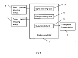
- FIG. 3 is a view showing the component modules of the electromotor control system to implement the electromotor control method in an embodiment of the present invention.
- FIG. 4 is a view showing the structure of a signal receiving module of the electromotor control system to implement the electromotor control method in an embodiment of the present invention.
- FIG. 5 is a view showing the structure of a resolver in the electromotor control system to implement the electromotor control method in an embodiment of the present invention.
- FIG. 6 is a view showing the waveform of an actual magnetic exciting signal of the resolver in the electromotor control system to implement the electromotor control method in an embodiment of the present invention.
- FIG. 7 is a view showing a sine output signal waveform of the resolver in the electromotor control system to implement the electromotor control method in an embodiment of the present invention.
- FIG. 8 is a view showing a cosine output signal waveform of the resolver in the electromotor control system to implement the electromotor control method in an embodiment of the present invention.
- FIG. 9 is a view showing the principle diagram of the electromotor control system to implement the electromotor control method in an embodiment of the present invention.
- the electromotor control method provided in the present invention comprises the steps of: setting a target alternating axis current iq* based on a target rotor angular velocity w* of the electromotor and setting a target direct axis current id* based on the torque of the electromotor; simultaneously detecting and collecting present three-phase currents ia, ib and ic of the electromotor and current rotor position angle ⁇ of the electromotor; determining an actual direct axis current id and an actual alternating axis current iq of the electromotor rotor by performing Park conversion and Clark conversion to the present three-phase currents ia, ib and ic; inputting the difference between the target alternating axis current iq* and the actual alternating axis current iq, and the difference between the target direct axis current id* and the actual direct axis current id to a current loop, and further outputting a required direct current id′ and a required alternating current iq
- FIG. 2 is a view of a current loop feedback circuit of the electromotor to implement the above steps.
- FIG. 3 is a view showing the components of the electromotor control system to implement the electromotor control method in an embodiment of the present invention.
- Said control system comprises: a phase current detecting device 1 , a rotor position detecting device 4 , an electromotor ECU 7 and a three-phase inverse device 6 ; wherein the electromotor ECU 7 comprises a signal receiving unit 71 , a data processing unit 72 and an output control unit 73 ; wherein said signal receiving unit 71 is configured to receive a phase current signal and a rotor position angle signal detected and output by the phase current detecting device 1 and the rotor position detecting device 4 , respectively.
- said signal receiving unit 71 is configured to determine the phase current value and the rotor position angle ⁇ of the electromotor therein; said data processing unit 72 calculates a PWM control waveform based on the rotor position angle ⁇ and the phase current output by the signal receiving unit 71 and outputs said waveform to the output control unit 73 ; said output control unit 73 outputs the received PWM control waveform to the three-phase inverse device 6 ; said three-phase inverse device 6 converts the received direct current to a three-phase alternating current in order to drive the electromotor.
- Said phase current detecting device 1 can be any apparatus capable of detecting three-phase currents, such as an alternating current sensor.
- said electromotor control system further comprises a phase current signal conditioning circuit located between the alternating current sensor and the signal receiving unit 71 ; wherein said conditioning circuit comprises a voltage uplifting circuit and a second-order filter circuit.
- the conditioning circuit is used to convert the phase current signal to an input signal amplitude corresponding to the signal receiving unit 71 in the electromotor ECU 7 .
- the components and the structure of the voltage uplifting circuit and the second-order filter circuit are known to those skilled in the art.
- the phase current signal will have phase shifting when it passes through the signal conditioning circuit.
- Said rotor position detecting device 4 may be any apparatus capable of detecting position angle of the rotor, such as a resolver.
- the resolver has only three coils embedded inside and has no other electric elements. Therefore, it has relatively good resistance to oscillations, temperature, corrosion and interference. It can further be configured to meet the requirements of different operation conditions and high reliability.
- the interior structure of the resolver is shown in FIG. 5 .
- S 1 -S 2 is an input excitation winding.
- S 3 -S 4 is a sine output winding.
- S 5 -S 6 is a cosine output winding.
- the resolver has one sine excitation signal as input and two-phase orthogonal sine signals as output.
- An independent winding on the rotor generates a coupling magnetic field while rotating.
- FIG. 6 is a view of an actual waveform of the excitation winding signal.
- the rotor axis angle can be determined using the amplitude and the polarity of the detected sine and cosine signals.
- the resolver further comprises a resolving unit to sample the analog signal of the rotor position output from the resolver and to convert it to a digital rotor position angle ⁇ of the electromotor. Said resolving unit will be further explained in the receiving unit 71 of the electromotor ECU 7 .
- said control system may further comprise a differential power amplifying unit connected between the input winding of the resolver and the signal receiving unit 71 .
- the differential power amplifying unit is configured to reduce waveform distortion effectively.
- Said control system may further comprise a low pass filter unit connected between the two output windings of the resolver and the receiving unit 71 .
- Said low pass filter unit is configured to resist interference and further restrict the amplitude of the sine and the cosine signals output from the resolver to conform to the requirements of the signal receiving unit 71 of the electromotor ECU 7 .
- said low pass filter unit is a ⁇ form RC filter.
- the receiving unit 71 of said electromotor ECU 7 is configured to receive signals output from the rotor position detecting device 4 and the phase current detecting device 1 , respectively.
- Said signal receiving unit 71 may comprise a signal receiving circuit, an A/D converting circuit and a filtering circuit.
- the structure of said signal receiving unit 71 is known to those skilled in the art.
- said signal receiving unit 71 comprises a resolving unit 711 , which is configured to sample and calculate the analog rotor position angle signal output from the rotor position detecting device 4 , convert it into a digital rotor position angle ⁇ , and further output the converted digital rotor position angle ⁇ to the data processing unit 72 of the electromotor ECU 7 .
- the resolving unit 711 calculates the position of the electromotor rotor based on the sine signal and the cosine signal output from the resolver, defining the electromotor rotor position angle ⁇ to be between 0° and 360° such that the corresponding output electromotor rotor position angle ⁇ of the resolving unit 711 is between 0 and 4095.
- the defined value can be determined by those of skilled in the art based on the specific requirements and the sampling precision.
- said signal receiving unit further comprises a velocity converting unit 712 , which is used to convert the rotor position angle ⁇ of the electromotor to a current rotor angular velocity co and a current rotor acceleration of the electromotor.
- the velocity converting unit 712 is known to those skilled in the art.
- said control method further comprises a step to remove the bad values of the angle.
- said method further comprises an angle compensation step and a slipping treating step.
- said signal receiving unit 71 further comprises an angle bad value removing unit 714 to remove the bad values of the angle, an angle compensation unit 715 to perform angle compensation, and a slipping treating unit to manage slipping status.
- Removing the bad values of the angle comprises the steps of: sampling the rotor angular velocity ⁇ of the electromotor at interval; multiplying the sampling time interval t with the rotor angular velocity ⁇ of the electromotor; adding a rotor position angle ⁇ 2 of the electromotor at a former sampling time interval to obtain a correction angle value ⁇ 1 ′; calculating the difference ⁇ between a current electromotor rotor angle ⁇ 1 and the former electromotor rotor angle ⁇ 2 ; setting the current angle correction value ⁇ 1 ′ to be the current electromotor rotor position angle value ⁇ 1 , if ⁇ is beyond a pre-determined error range.
- the angle compensation step is described in detail herein below.
- the angle compensation step stops outputting the PWM control waveform such that the rotation of the electromotor is terminated; wherein the predetermined time interval T is 1 to 3 minutes and the predetermined value N is 4 to 6 times.
- setting the predetermined time interval T as 3 minutes and the predetermined value N as 4 means that if within 3 minutes, the frequency of ⁇ being outside the predetermined error range is greater than 4, the angle compensation unit 722 will send a signal to the output control unit 73 to stop outputting the PWM control waveform.
- the control method improves the anti-interference performance in angle detection such that the control losing situation of an electromotor due to rotor position error can be avoided; but also the control method enhances the stability and reliability of the electromotor such that the operation termination situation of an electromotor due to occasional interference can be avoided.
- the slipping treating step is described in detail herein below.
- the slipping treating step calculates the current rotary velocity.
- the slipping treating step determines whether the current rotary velocity of the electromotor rotor is greater than a predetermined maximum acceleration value, if true, performing slipping management to eliminate the slipping of an electric vehicle, further, the torque of the electromotor is reduced to eliminate the slipping; wherein the slipping treating scheme is known to those skilled in the field.
- the control method provided in the present invention employs slipping treating step, detecting whether the wheels of the electric vehicle are in slipping status based on the rotor's position rather than based on the comparison between the velocity of the driving wheels and the driven wheels in the prior art. Accordingly, the control method provided in the present invention saves the velocity sensors installed on the driven wheels and achieves faster responding speed and relatively higher accuracy.
- the correction angle 102° ⁇ (the current angular velocity ⁇ of the electromotor rotor/1100).
- 102° refers to a signal phase shifting parameter of the analog circuit detected by the signal generator at the current rotor angular velocity ⁇ of the electromotor of 1100 rad/s, wherein the phase shifting is essentially increased linearly with the increasing of the rotor angular velocity ⁇ of the electromotor. Accordingly, the signal after compensation is restored to a signal which conforms to an actual current of the electromotor.
- the data processing unit 72 of said electromotor ECU 7 is configured to process the data output from the signal receiving unit 71 according to the steps detailed herein below:
- the method of setting the target direct axis current id based on the rotor angular velocity ⁇ of the electromotor and setting the target alternating axis current iq based on the torque of the electromotor is known to those skilled in this field.
- iq iq ⁇ ⁇ max ⁇ T T ⁇ ⁇ max
- the maximum torque of the electromotor Tmax is default for a given electromotor.
- Said method of calculating the target direct current id according to the electromotor rotor angular velocity ⁇ can be any available methods known to those skilled in the art. For example, one calculation method is detailed as below: since the rotor angular velocity ⁇ is linear to the direct current id, the method selects an initial rotor angular velocity ⁇ 1 when the target direct current id is 0, a direct current id 1 when the electromotor rotor angular velocity ⁇ is 0, a constant maximum rotor angular velocity ⁇ max of the electromotor, a direct current id 2 corresponding to the maximum rotor angular velocity ⁇ max and the current rotor angular velocity ⁇ of the electromotor, and further calculates the target direct axis current id, wherein
- id ( id ⁇ ⁇ 2 - id ⁇ ⁇ 1 ) ⁇ ⁇ - ⁇ ⁇ ⁇ 1 ⁇ ⁇ ⁇ max . Further, the calculation can be done in separate sections because the rotor angular velocity ⁇ of the electromotor may be linear to the direct current id in separate sections.
- the torque of the electromotor is calculated based on the depth of an accelerator, the depth of a break and a shifting information; wherein the depth of the accelerator and the depth of the break are detected and transmitted to the electromotor control ECU by a sensor, and the shifting information includes: hand break (HB), foot break (FB), parking position (P), reverse position (R), neutral position (N) and driving position (D).
- the electromotor and the wheels of the electric vehicle are mechanically connected by gears with a transformation ratio of 5.4:1. Speed of an electric vehicle is controlled by the electromotor rotation speed, which is adjusted by pressing the accelerator. Therefore, a continuous variable transmission can be achieved.
- u ⁇ ( t ) Kp ⁇ [ e ⁇ ( t ) + 1 Ti ⁇ ⁇ 0 t ⁇ e ⁇ ( t ) ⁇ d t ]
- Kp is a proportional coefficient
- Ti is an integration coefficient (also works as integration time). Both are determined by practical matching according to vehicle service quality and motor working condition.
- the role of Kp is to accelerate the responding speed and to enhance the regulation accuracy of the system. When Kp increases, the responding speed of the system gets faster, and the regulation accuracy gets higher. However, the system may easily get over-regulated, thus the stability may get worse. If the value of Kp is too small, the regulation accuracy will decrease, the responding speed will be slower and the time required for regulation will be prolonged. Accordingly, the dynamic and static performances of the system will deteriorate.
- the role of Ti is to eliminate the steady-state error. The larger Ti is, the faster the system eliminates the steady-state error. However, if the value of Ti is too large, the integration saturation will arise at the beginning of the responding process; if the value of Ti is too small, the steady-state error is difficult to eliminate. Accordingly, too small value of Ti will affect the regulation accuracy of the system.
- the predetermined rotating speed threshold value and the predetermined high speed PI integration frequency are determined based on the condition of the electromotor. For example, if the predetermined rotating speed threshold value is 300-500 rad/min, the predetermined high speed integration frequency is 2000-10000 Hz and the predetermined low speed PI integration frequency is 500-1000 Hz.
- the predetermined rotating speed threshold value is 300 rad/min
- the predetermined high speed PI integration frequency is 2000 Hz
- the predetermined low speed PI integration speed is 500 Hz, i.e., when the rotating speed of the electromotor is greater than 300 rad/min, setting the integration frequency of the PI regulator to be 2000 Hz, and when the rotating speed of the electromotor is lower than 300 rad/min, setting the integration frequency of the PI regulator to be 500 Hz.
- the rotating speed of the electromotor rotor can be obtained using a conversion of the rotor angular velocity ⁇ of the electromotor, wherein the conversion equation is known to those skilled in the art.
- the rotating speed of the electromotor rotor is the number of the rotated circles in one minute
- the rotor angular velocity ⁇ of the electromotor is the rotated radian in one second.
- the control method provided in the present invention employs the frequency regulation step, which eliminates the over-regulation of the PI integration due to high speed regulation. As a result, it ensures the stable operation of the electromotor at a low speed.
- the output control unit 73 of said electromotor ECU 7 is configured to output the PWM control waveform obtained in the data processing unit 72 to the three-phase inverse device 6 .
- Each unit and subunit of said electromotor ECU 7 can be implemented by employing circuits for separate components, by a single chip computer with integrated processors, or by a special electromotor control processor DSP.
- the role of said three-phase inverse device 6 is to convert direct voltage into three-phase alternating voltage in order to drive the motor, wherein said three-phase inverse device 6 comprises a direct current input end, an alternating output end, multiple IPMs and a driving board; wherein said driving board is configured to receive the PWM control waveform from the output control unit 73 and control the connecting sequence, shut-off time and connecting time of the multiple IPMs based on said PWM control waveform. For example, as shown in FIG. 9 , three-three connecting is employed.
- the three-phase inverse device 6 comprises U phase branch circuits connected in parallel, V phase branch circuits and W phase branch circuits, alternating output ends connected to the outlet terminals of the windings U, V and W of the permanent magnet synchronized electromotor M respectively, a direct current input end connected to battery B, wherein two IPMs serially connected are set in each phase branch circuit.
- Each IPM comprises an IGBT (Insulated Gate Bipolar Transistor) (one of T 1 -T 6 ) and a fly-wheel diode D which is reversely connected to each IGBT and a protection circuit of IGBT in parallel.
- the joint of the two IPMs serially connected in each branch circuit is connected to a respective alternating current input end of each branch circuit.
- the other unconnected ends of the two IPMs in each branch circuit are parallel to each other and connected to the direct current output ends.
- Said driving board is further used to insulate the PWM control waveform, to amplify and to drive the electromotor.
- FIG. 9 is a principle drawing of the electromotor control system of the electromotor control method provided in the present invention.
- the working principle of said three-phase inverse device 6 is described in detail according to FIG. 9 : at a certain point, T 1 , T 6 and T 2 are conducted, the current flows from the up bridge arm T 1 to T 6 and T 2 at the same time; when T 1 , T 6 and T 2 are shut off, as the stator of the electromotor continues to rotate and cut the magnetic lines, the current dramatically changes and the result of L ⁇ di/dt enlarges. Even the rotating speed of the electromotor is very low, a high induction electromotive force can be generated.
- a capacitor is connected in parallel between the two direct current input ends of the three-phase inverse device 6 to smooth the direct voltage.
Abstract
Description
Vs1— s2=Vp×Sin(ωt)
Vs3— s4=Vs×Sin(ωt)×Sin θ (1)
Vs5— s6=Vs×Sin(ωt)×cos θ (2)
Wherein Vs=kVp. k is a transfer ratio.
According to Eq. (1) and Eq. (2), we have
Tan θ=Vs3— s4/Vs5— s6 (3)
Further, the calculation can be done in separate sections because the rotor angular velocity ω of the electromotor may be linear to the direct current id in separate sections.
ud=
uq=−(
Wherein, Ld is a direct axis inductance; Lq is an alternating axis inductance; Ψ is a permanent magnet chain of the rotor; R is an electromotor impedance. These values can be measured and calculated on a given motor, wherein the calculation method is known to those skilled in this field.
Claims (9)
Applications Claiming Priority (1)
| Application Number | Priority Date | Filing Date | Title |
|---|---|---|---|
| PCT/CN2006/002916 WO2008052388A1 (en) | 2006-10-31 | 2006-10-31 | Control method of electromotor |
Publications (2)
| Publication Number | Publication Date |
|---|---|
| US20100000815A1 US20100000815A1 (en) | 2010-01-07 |
| US8207701B2 true US8207701B2 (en) | 2012-06-26 |
Family
ID=39343786
Family Applications (1)
| Application Number | Title | Priority Date | Filing Date |
|---|---|---|---|
| US12/447,429 Active 2028-01-30 US8207701B2 (en) | 2006-10-31 | 2006-10-31 | Control method of electromotor |
Country Status (5)
| Country | Link |
|---|---|
| US (1) | US8207701B2 (en) |
| EP (1) | EP2063339B1 (en) |
| CN (1) | CN101535913B (en) |
| DE (1) | DE602006021238D1 (en) |
| WO (1) | WO2008052388A1 (en) |
Cited By (4)
| Publication number | Priority date | Publication date | Assignee | Title |
|---|---|---|---|---|
| US20140132196A1 (en) * | 2011-06-15 | 2014-05-15 | Renault S.A.S. | Method and device for controlling an electric motor propulsion unit with decoupled controls |
| US20140217946A1 (en) * | 2013-02-01 | 2014-08-07 | Kabushiki Kaisha Yaskawa Denki | Inverter device and motor drive system |
| US20170045870A1 (en) * | 2015-03-13 | 2017-02-16 | Lite-On Electronics (Guangzhou) Limited | Method and system for estimating operation parameters of a servomotor |
| US10215784B1 (en) * | 2017-12-05 | 2019-02-26 | Industrial Technology Research Institute | Measuring apparatus including phase locked loop and measuring method thereof |
Families Citing this family (29)
| Publication number | Priority date | Publication date | Assignee | Title |
|---|---|---|---|---|
| US7600593B2 (en) * | 2007-01-05 | 2009-10-13 | Irobot Corporation | Robotic vehicle with dynamic range actuators |
| CN102082532B (en) * | 2009-11-28 | 2013-09-18 | 比亚迪股份有限公司 | Motor drive control system and control method thereof |
| KR101294566B1 (en) * | 2010-12-01 | 2013-08-07 | 기아자동차주식회사 | An apparatus for adaptively compensating position error of resolver |
| DE102011075238A1 (en) * | 2011-05-04 | 2012-11-08 | Robert Bosch Gmbh | Method and device for monitoring an angular position of a rotor in an electric machine |
| CN102611143B (en) * | 2012-03-14 | 2014-03-19 | 电子科技大学 | Method for controlling grid-connected current of three-phase grid-connected inverter |
| CN102611339B (en) * | 2012-03-14 | 2014-03-19 | 电子科技大学 | Current control method for three-phase rectifying device |
| CN102818581B (en) * | 2012-07-12 | 2015-01-07 | 武汉迈信电气技术有限公司 | Incremental encoder based on rotary transformer |
| CN103701372B (en) | 2012-09-27 | 2017-07-04 | 比亚迪股份有限公司 | A kind of step failing out detecting method of synchronous motor |
| CN102882457B (en) * | 2012-10-10 | 2015-04-22 | 深圳市航盛电子股份有限公司 | Traction motor control device and method |
| CN104518722B (en) * | 2013-10-08 | 2018-01-02 | 广东美的制冷设备有限公司 | The torque compensation control system and its torque compensation control method of synchronous motor |
| CN103944469B (en) * | 2014-05-12 | 2016-07-06 | 南京国电南自美卓控制系统有限公司 | A kind of universal generator exciting power cell power device triggering system and method |
| KR101664567B1 (en) | 2014-10-20 | 2016-10-10 | 현대자동차주식회사 | Apparatus and Method for Compensating Position Information Error of Resolver |
| CN105857475B (en) * | 2015-01-21 | 2019-05-10 | 常州爱尔威智能科技有限公司 | A kind of Two-wheeled Intelligent self-balancing battery-operated motor cycle and its progress control method |
| CN104730339A (en) * | 2015-03-15 | 2015-06-24 | 华南理工大学 | Digital phase lock method in condition of unsymmetrical three-phase voltage |
| CN104808089B (en) * | 2015-05-08 | 2017-12-08 | 贵州电力试验研究院 | Low-frequency oscillation detection method and system based on generator terminal three-phase voltage signal |
| CN106569076B (en) * | 2015-10-13 | 2019-04-02 | 湖南三一电控科技有限公司 | Asynchronous motor three-phase sequence misconnection detection system and method |
| JP6708358B2 (en) * | 2016-08-03 | 2020-06-10 | 株式会社日立ハイテク | Plasma processing apparatus and sample separation method |
| CN107147343A (en) * | 2017-06-02 | 2017-09-08 | 深圳市奇诺动力科技有限公司 | Brushless electric machine Field orientable control drive system and control method |
| CN108388279B (en) * | 2018-02-12 | 2021-09-17 | 浙江中控技术股份有限公司 | Control method and device for high-speed rotating mechanical equipment |
| CN109156156B (en) * | 2018-09-18 | 2023-04-18 | 赣州双木科技有限公司 | Variable-speed adjusting device of tea garden harvesting robot and control method thereof |
| CN111371359A (en) * | 2018-12-24 | 2020-07-03 | 深圳市优必选科技有限公司 | Motor vector control method and device, terminal equipment and readable storage medium |
| CN111181559B (en) * | 2019-10-10 | 2023-05-05 | 中国第一汽车股份有限公司 | Method, device, equipment and storage medium for rotary soft decoding |
| CN110868115B (en) * | 2019-10-28 | 2022-04-29 | 深圳市汇川技术股份有限公司 | Motor suitable for sensorless control |
| CN110757458B (en) * | 2019-11-04 | 2020-08-21 | 成都卡诺普自动化控制技术有限公司 | Method for inhibiting robot joint from crawling at low speed |
| CN112448636B (en) * | 2020-12-04 | 2022-07-29 | 岳阳市爱达兴智能科技有限公司 | Method for controlling acceleration of electric vehicle |
| CN112713821B (en) * | 2020-12-17 | 2023-03-14 | 杭州海康威视数字技术股份有限公司 | Method and system for closed-loop control of brush motor |
| CN112763793B (en) * | 2020-12-25 | 2022-10-28 | 潍柴动力股份有限公司 | Current signal detection method and device, storage medium and motor controller |
| CN112865019A (en) * | 2020-12-31 | 2021-05-28 | 常熟开关制造有限公司(原常熟开关厂) | Motor protection method and device in variable frequency loop |
| CN112977173B (en) * | 2021-04-30 | 2022-05-03 | 重庆长安新能源汽车科技有限公司 | Electric automobile and power battery pulse heating system and heating method thereof |
Citations (14)
| Publication number | Priority date | Publication date | Assignee | Title |
|---|---|---|---|---|
| JPS61240884A (en) | 1985-04-17 | 1986-10-27 | Yaskawa Electric Mfg Co Ltd | Pole position correcting system for permanent magnet type linear pulse motor |
| EP0274582A2 (en) | 1987-01-09 | 1988-07-20 | Kabushiki Kaisha Toshiba | High-accuracy position detection apparatus |
| DE4321286A1 (en) | 1992-07-02 | 1994-01-05 | Vaillant Joh Gmbh & Co | Closed loop digital regulator for electromotor - has two-point feed forward component added in to provide PWM control action |
| JPH07327382A (en) | 1994-05-30 | 1995-12-12 | Fanuc Ltd | Control system for ac motor |
| JPH11337372A (en) | 1998-05-27 | 1999-12-10 | Toyota Motor Corp | Abnormality detecting equipment for ic chip |
| US20020047680A1 (en) | 2000-02-17 | 2002-04-25 | Bernhard Frenzel | Method for current regulation of permanently excited synchronous motors for guided missiles having an electromechanical actuating drive for the rudder |
| US6501998B1 (en) | 1997-05-28 | 2002-12-31 | Siemens Aktiengesellschaft | Method for controlling a time-lagged process with compensation, and a controlling device for carrying out said method |
| JP2003189700A (en) | 2001-12-13 | 2003-07-04 | Mitsubishi Heavy Ind Ltd | Motor controller, driving method for motor, and program for controlling motor |
| US20030212516A1 (en) * | 2001-02-01 | 2003-11-13 | Ulrich James A. | Method and system of harmonic regulation |
| CN1515068A (en) | 2002-02-25 | 2004-07-21 | 大金工业株式会社 | Motor control method and its apparatus |
| US20090244937A1 (en) * | 2008-03-28 | 2009-10-01 | American Superconductor Corporation | Dc bus voltage harmonics reduction |
| US20100057284A1 (en) * | 2006-12-26 | 2010-03-04 | Byd Company Limited | Method and apparatus for controlling motor for skid mode of electric vehicle |
| US20100301787A1 (en) * | 2009-05-28 | 2010-12-02 | Gm Global Technology Operations, Inc. | Methods, systems and apparatus for controlling operation of two alternating current (ac) machines |
| US20110050141A1 (en) * | 2009-08-31 | 2011-03-03 | Gm Global Technology Operations, Inc. | Electric motor stator winding temperature estimation |
-
2006
- 2006-10-31 WO PCT/CN2006/002916 patent/WO2008052388A1/en active Application Filing
- 2006-10-31 US US12/447,429 patent/US8207701B2/en active Active
- 2006-10-31 EP EP06817796A patent/EP2063339B1/en active Active
- 2006-10-31 CN CN2006800562591A patent/CN101535913B/en active Active
- 2006-10-31 DE DE602006021238T patent/DE602006021238D1/en active Active
Patent Citations (14)
| Publication number | Priority date | Publication date | Assignee | Title |
|---|---|---|---|---|
| JPS61240884A (en) | 1985-04-17 | 1986-10-27 | Yaskawa Electric Mfg Co Ltd | Pole position correcting system for permanent magnet type linear pulse motor |
| EP0274582A2 (en) | 1987-01-09 | 1988-07-20 | Kabushiki Kaisha Toshiba | High-accuracy position detection apparatus |
| DE4321286A1 (en) | 1992-07-02 | 1994-01-05 | Vaillant Joh Gmbh & Co | Closed loop digital regulator for electromotor - has two-point feed forward component added in to provide PWM control action |
| JPH07327382A (en) | 1994-05-30 | 1995-12-12 | Fanuc Ltd | Control system for ac motor |
| US6501998B1 (en) | 1997-05-28 | 2002-12-31 | Siemens Aktiengesellschaft | Method for controlling a time-lagged process with compensation, and a controlling device for carrying out said method |
| JPH11337372A (en) | 1998-05-27 | 1999-12-10 | Toyota Motor Corp | Abnormality detecting equipment for ic chip |
| US20020047680A1 (en) | 2000-02-17 | 2002-04-25 | Bernhard Frenzel | Method for current regulation of permanently excited synchronous motors for guided missiles having an electromechanical actuating drive for the rudder |
| US20030212516A1 (en) * | 2001-02-01 | 2003-11-13 | Ulrich James A. | Method and system of harmonic regulation |
| JP2003189700A (en) | 2001-12-13 | 2003-07-04 | Mitsubishi Heavy Ind Ltd | Motor controller, driving method for motor, and program for controlling motor |
| CN1515068A (en) | 2002-02-25 | 2004-07-21 | 大金工业株式会社 | Motor control method and its apparatus |
| US20100057284A1 (en) * | 2006-12-26 | 2010-03-04 | Byd Company Limited | Method and apparatus for controlling motor for skid mode of electric vehicle |
| US20090244937A1 (en) * | 2008-03-28 | 2009-10-01 | American Superconductor Corporation | Dc bus voltage harmonics reduction |
| US20100301787A1 (en) * | 2009-05-28 | 2010-12-02 | Gm Global Technology Operations, Inc. | Methods, systems and apparatus for controlling operation of two alternating current (ac) machines |
| US20110050141A1 (en) * | 2009-08-31 | 2011-03-03 | Gm Global Technology Operations, Inc. | Electric motor stator winding temperature estimation |
Non-Patent Citations (3)
| Title |
|---|
| European Patent Application 06817796.3, Office Action dated Jan. 7, 2010, 6 pgs. |
| International Search Report; PCT/CN2006/002916; Aug. 9, 2007; 3 pages. |
| Wang et al.; Speed-adjustment System of Permanent Magnet Synchronous Generator; Small & Special Machines, No. 9, 2004. |
Cited By (7)
| Publication number | Priority date | Publication date | Assignee | Title |
|---|---|---|---|---|
| US20140132196A1 (en) * | 2011-06-15 | 2014-05-15 | Renault S.A.S. | Method and device for controlling an electric motor propulsion unit with decoupled controls |
| US9608553B2 (en) * | 2011-06-15 | 2017-03-28 | Renault S.A.S. | Method and device for controlling an electric motor propulsion unit with decoupled controls |
| US20140217946A1 (en) * | 2013-02-01 | 2014-08-07 | Kabushiki Kaisha Yaskawa Denki | Inverter device and motor drive system |
| US9252698B2 (en) * | 2013-02-01 | 2016-02-02 | Kabushiki Kaisha Yaskawa Denki | Inverter device and motor drive system |
| US20170045870A1 (en) * | 2015-03-13 | 2017-02-16 | Lite-On Electronics (Guangzhou) Limited | Method and system for estimating operation parameters of a servomotor |
| US9768720B2 (en) * | 2015-03-13 | 2017-09-19 | Lite-On Electronics (Guangzhou) Limited | Method and system for estimating operation parameters of a servomotor |
| US10215784B1 (en) * | 2017-12-05 | 2019-02-26 | Industrial Technology Research Institute | Measuring apparatus including phase locked loop and measuring method thereof |
Also Published As
| Publication number | Publication date |
|---|---|
| EP2063339A4 (en) | 2010-02-03 |
| CN101535913B (en) | 2011-03-02 |
| WO2008052388A1 (en) | 2008-05-08 |
| EP2063339A1 (en) | 2009-05-27 |
| US20100000815A1 (en) | 2010-01-07 |
| CN101535913A (en) | 2009-09-16 |
| EP2063339B1 (en) | 2011-04-06 |
| DE602006021238D1 (en) | 2011-05-19 |
Similar Documents
| Publication | Publication Date | Title |
|---|---|---|
| US8207701B2 (en) | Control method of electromotor | |
| EP2754998B1 (en) | Error frequency component acquisition device, angle of rotation acquisition device, motor control device, and angle of rotation acquisition method | |
| EP1796257B1 (en) | Position detecting device and synchronous motor driving device using the same | |
| EP2709267B1 (en) | Drive system for synchronous motor | |
| EP2888141B1 (en) | System and method for error correction in angular position sensors | |
| US7538700B2 (en) | Angular position detector and rotary electric device drive unit including the same | |
| US6515446B1 (en) | Motor control apparatus and control method | |
| EP2779415A2 (en) | Motor control system to compensate for torque ripple | |
| US20140327379A1 (en) | Position sensorless drive system and method for permanent magnet motors | |
| EP1298783A2 (en) | Switching methodology for ground referenced voltage controlled electric machine | |
| JP2006054995A (en) | Drive control device and method for ac motor | |
| US10439538B2 (en) | Method and system for estimating a rotor position with a notch filter | |
| JPH07245981A (en) | Detector for position of magnetic pole in motor | |
| EP1583217B1 (en) | Motor drive-controlling device and electric power-steering device | |
| CN109039199B (en) | Bus current estimation method and system for EPS controller | |
| JP5170505B2 (en) | Motor control device | |
| US7579804B2 (en) | Method to measure the angular speed of an induction motor | |
| JP3707528B2 (en) | AC motor control method and control apparatus therefor | |
| JP5338110B2 (en) | Motor drive device and control method thereof | |
| US20160156294A1 (en) | Motor driving module | |
| KR100432389B1 (en) | Inverter | |
| CN212183431U (en) | Control circuit and rail vehicle | |
| US11316460B2 (en) | Motor position calibration | |
| JP2003509997A (en) | Torque current comparison for current validity diagnosis in permanent magnet electric machines | |
| US11626821B2 (en) | Sensorless control of a motor by variable frequency signal injection |
Legal Events
| Date | Code | Title | Description |
|---|---|---|---|
| AS | Assignment |
Owner name: BYD COMPANY LTD.,CHINA Free format text: ASSIGNMENT OF ASSIGNORS INTEREST;ASSIGNORS:TANG, XIAOHUA;ZHOU, XUGUANG;LUO, HONGBIN;AND OTHERS;SIGNING DATES FROM 20090317 TO 20090729;REEL/FRAME:024604/0493 Owner name: BYD COMPANY LTD., CHINA Free format text: ASSIGNMENT OF ASSIGNORS INTEREST;ASSIGNORS:TANG, XIAOHUA;ZHOU, XUGUANG;LUO, HONGBIN;AND OTHERS;SIGNING DATES FROM 20090317 TO 20090729;REEL/FRAME:024604/0493 |
|
| STCF | Information on status: patent grant |
Free format text: PATENTED CASE |
|
| CC | Certificate of correction | ||
| FPAY | Fee payment |
Year of fee payment: 4 |
|
| MAFP | Maintenance fee payment |
Free format text: PAYMENT OF MAINTENANCE FEE, 8TH YEAR, LARGE ENTITY (ORIGINAL EVENT CODE: M1552); ENTITY STATUS OF PATENT OWNER: LARGE ENTITY Year of fee payment: 8 |
|
| MAFP | Maintenance fee payment |
Free format text: PAYMENT OF MAINTENANCE FEE, 12TH YEAR, LARGE ENTITY (ORIGINAL EVENT CODE: M1553); ENTITY STATUS OF PATENT OWNER: LARGE ENTITY Year of fee payment: 12 |