US7972749B2 - Low voltage power tap on high voltage stack - Google Patents
Low voltage power tap on high voltage stack Download PDFInfo
- Publication number
- US7972749B2 US7972749B2 US10/875,464 US87546404A US7972749B2 US 7972749 B2 US7972749 B2 US 7972749B2 US 87546404 A US87546404 A US 87546404A US 7972749 B2 US7972749 B2 US 7972749B2
- Authority
- US
- United States
- Prior art keywords
- tap
- fuel cell
- stack
- negative
- potential
- Prior art date
- Legal status (The legal status is an assumption and is not a legal conclusion. Google has not performed a legal analysis and makes no representation as to the accuracy of the status listed.)
- Expired - Fee Related, expires
Links
Images

Classifications
-
- H—ELECTRICITY
- H01—ELECTRIC ELEMENTS
- H01M—PROCESSES OR MEANS, e.g. BATTERIES, FOR THE DIRECT CONVERSION OF CHEMICAL ENERGY INTO ELECTRICAL ENERGY
- H01M8/00—Fuel cells; Manufacture thereof
- H01M8/04—Auxiliary arrangements, e.g. for control of pressure or for circulation of fluids
- H01M8/04298—Processes for controlling fuel cells or fuel cell systems
- H01M8/04694—Processes for controlling fuel cells or fuel cell systems characterised by variables to be controlled
- H01M8/04858—Electric variables
- H01M8/04865—Voltage
- H01M8/0488—Voltage of fuel cell stacks
-
- B—PERFORMING OPERATIONS; TRANSPORTING
- B60—VEHICLES IN GENERAL
- B60L—PROPULSION OF ELECTRICALLY-PROPELLED VEHICLES; SUPPLYING ELECTRIC POWER FOR AUXILIARY EQUIPMENT OF ELECTRICALLY-PROPELLED VEHICLES; ELECTRODYNAMIC BRAKE SYSTEMS FOR VEHICLES IN GENERAL; MAGNETIC SUSPENSION OR LEVITATION FOR VEHICLES; MONITORING OPERATING VARIABLES OF ELECTRICALLY-PROPELLED VEHICLES; ELECTRIC SAFETY DEVICES FOR ELECTRICALLY-PROPELLED VEHICLES
- B60L50/00—Electric propulsion with power supplied within the vehicle
- B60L50/50—Electric propulsion with power supplied within the vehicle using propulsion power supplied by batteries or fuel cells
- B60L50/70—Electric propulsion with power supplied within the vehicle using propulsion power supplied by batteries or fuel cells using power supplied by fuel cells
- B60L50/72—Constructional details of fuel cells specially adapted for electric vehicles
-
- H—ELECTRICITY
- H01—ELECTRIC ELEMENTS
- H01M—PROCESSES OR MEANS, e.g. BATTERIES, FOR THE DIRECT CONVERSION OF CHEMICAL ENERGY INTO ELECTRICAL ENERGY
- H01M8/00—Fuel cells; Manufacture thereof
- H01M8/24—Grouping of fuel cells, e.g. stacking of fuel cells
- H01M8/241—Grouping of fuel cells, e.g. stacking of fuel cells with solid or matrix-supported electrolytes
-
- H—ELECTRICITY
- H01—ELECTRIC ELEMENTS
- H01M—PROCESSES OR MEANS, e.g. BATTERIES, FOR THE DIRECT CONVERSION OF CHEMICAL ENERGY INTO ELECTRICAL ENERGY
- H01M2250/00—Fuel cells for particular applications; Specific features of fuel cell system
- H01M2250/20—Fuel cells in motive systems, e.g. vehicle, ship, plane
-
- Y—GENERAL TAGGING OF NEW TECHNOLOGICAL DEVELOPMENTS; GENERAL TAGGING OF CROSS-SECTIONAL TECHNOLOGIES SPANNING OVER SEVERAL SECTIONS OF THE IPC; TECHNICAL SUBJECTS COVERED BY FORMER USPC CROSS-REFERENCE ART COLLECTIONS [XRACs] AND DIGESTS
- Y02—TECHNOLOGIES OR APPLICATIONS FOR MITIGATION OR ADAPTATION AGAINST CLIMATE CHANGE
- Y02E—REDUCTION OF GREENHOUSE GAS [GHG] EMISSIONS, RELATED TO ENERGY GENERATION, TRANSMISSION OR DISTRIBUTION
- Y02E60/00—Enabling technologies; Technologies with a potential or indirect contribution to GHG emissions mitigation
- Y02E60/30—Hydrogen technology
- Y02E60/50—Fuel cells
-
- Y—GENERAL TAGGING OF NEW TECHNOLOGICAL DEVELOPMENTS; GENERAL TAGGING OF CROSS-SECTIONAL TECHNOLOGIES SPANNING OVER SEVERAL SECTIONS OF THE IPC; TECHNICAL SUBJECTS COVERED BY FORMER USPC CROSS-REFERENCE ART COLLECTIONS [XRACs] AND DIGESTS
- Y02—TECHNOLOGIES OR APPLICATIONS FOR MITIGATION OR ADAPTATION AGAINST CLIMATE CHANGE
- Y02T—CLIMATE CHANGE MITIGATION TECHNOLOGIES RELATED TO TRANSPORTATION
- Y02T90/00—Enabling technologies or technologies with a potential or indirect contribution to GHG emissions mitigation
- Y02T90/40—Application of hydrogen technology to transportation, e.g. using fuel cells
Definitions
- This invention relates generally to a fuel cell stack employing a low voltage tap and, more particularly, to a fuel cell stack having one or more low voltage power taps for providing low voltage DC power for low voltage devices in a fuel cell system or AC power to other devices in the system.
- Hydrogen is a very attractive fuel because it is clean and can be used to efficiently produce electricity in a fuel cell.
- the automotive industry expends significant resources in the development of hydrogen fuel cells as a source of power for vehicles. Such vehicles would be more efficient and generate fewer emissions than today's vehicles employing internal combustion engines.
- a hydrogen fuel cell is an electrochemical device that includes an anode and a cathode with an electrolyte therebetween.
- the anode receives hydrogen gas and the cathode receives oxygen or air.
- the hydrogen gas is disassociated in the anode to generate free hydrogen protons and electrons.
- the hydrogen protons pass through the electrolyte to the cathode.
- the hydrogen protons react with the oxygen and the electrons in the cathode to generate water.
- the electrons from the anode cannot pass through the electrolyte, and thus are directed through a load to perform work before being sent to the cathode. The work acts to operate the vehicle.
- PEMFC Proton exchange membrane fuel cells
- the PEMFC generally includes a solid polymer electrolyte proton conducting membrane, such as a perfluorosulfonic acid membrane.
- the anode and cathode typically include finely divided catalytic particles, usually platinum (Pt), supported on carbon particles and mixed with an ionomer.
- Pt platinum
- the combination of the anode, cathode and membrane define a membrane electrode assembly (MEA).
- MEAs are relatively expensive to manufacture and require certain conditions for effective operation. These conditions include proper water management and humidification, and control of catalyst poisoning constituents, such as carbon monoxide (CO).
- CO carbon monoxide
- a typical fuel cell stack for an automobile may have two hundred stacked fuel cells.
- the fuel cell stack receives a cathode input gas as a flow of air, typically forced through the stack by a compressor. Not all of the oxygen in the air is consumed by the stack and some of the air is output as a cathode exhaust gas that may include water as a stack by-product.
- the fuel cell stack also receives an anode hydrogen input gas that flows into the anode side of the stack.
- the fuel cell stack includes a series of bipolar plates positioned between the several membranes in the stack.
- the stack would include about two hundred bipolar plates.
- the bipolar plates include an anode side and a cathode side for adjacent fuel cells in the stack.
- the bipolar plates are made of a conductive material, such as stainless steel, so that they conduct the electricity generated by the fuel cells out of the stack.
- the bipolar plates also include flow channels through which a cooling fluid and the anode and cathode gases for the electrochemical reaction flow, as is well understood in the art.
- Vehicles and other systems typically require 12 volt DC nominal power to provide power to various vehicle accessories, such as headlights, switches, etc.
- the 12 volt DC power is provided by a DC/DC converter that down-converts the high voltage from the fuel cell stack.
- the high voltage of the overall DC power from the fuel cell stack is down-converted by the DC/DC converter to the desired voltage level for the various low voltage devices.
- the DC/DC converter adds cost, mass, volume, losses and additional assembly costs to the fuel cell system.
- the DC/DC converter must include electrical isolation to prevent the chassis from coming in contact with the high voltage. This converter isolation also increases the cost, mass and losses associated with the system. It would be desirable to eliminate the DC/DC converter from the fuel cell system for these reasons.
- a fuel cell system includes a fuel cell stack providing high voltage DC output power, such as for operating a vehicle.
- the fuel cell stack includes a stack of fuel cells each being separated by a bipolar plate.
- a tap is electrically coupled to the end plate at the positive end of the stack to provide a positive voltage output terminal of the fuel cell stack, and a tap is electrically coupled to the end plate at the negative or ground end of the stack to provide a negative output terminal of the fuel cell stack.
- the total output voltage of the stack is provided across the positive and negative terminal taps.
- the fuel cell stack further includes one or more intermediate low voltage taps electrically coupled to one or more of the bipolar plates so that a low voltage potential is provided across the negative terminal tap and the intermediate taps to provide low voltage DC power for operating ancillary vehicle components.
- several intermediate taps are electrically coupled to various bipolar plates so that several DC voltage potentials are provided.
- a center intermediate tap is designated a reference potential tap, and the intermediate taps having a higher voltage potential than the reference potential are positive taps and the intermediate taps having a lower voltage potential than the reference voltage are negative taps.
- the several voltage potentials can be switched to provide an AC signal to drive AC components, such as three phase motors.
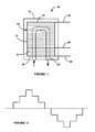
- FIG. 1 is a plan view of a fuel cell stack including an intermediate voltage potential tap, according to an embodiment of the present invention
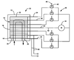
- FIG. 2 is a plan view of a fuel cell stack including a plurality of intermediate voltage potential taps and a switching network to provide an AC voltage potential, where one of the taps is designated a reference potential tap, according to another embodiment of the present invention.
- FIG. 3 is an AC signal generated by the switching network shown in FIG. 2 .
- FIG. 1 is a plan view of a fuel cell system 10 including an outer housing 12 .
- a fuel cell stack 14 is positioned within the housing 12 , and includes a plurality of stacked fuel cells 16 separated by bipolar plates 18 .
- the bipolar plates 18 include various flow channels for cooling fluids, anode gases and cathode gases to provide the necessary fuel and cooling to the fuel cells 16 .
- a coolant loop 20 flows through the fuel cells 16 to provide the coolant to the stack 14 .
- Each bipolar plate 18 includes an anode side and a cathode side for the anode and cathode of adjacent fuel cells.
- a positive terminal tap 24 is electrically coupled to an end plate 22 at the positive end of the fuel cell stack 14 and a negative terminal tap 26 is electrically coupled to an end plate 30 at the negative or ground end of the fuel cell stack 14 .
- operation of the fuel cell stack 14 causes the fuel cells 16 to generate electrical DC power in series so that a high voltage output potential is provided across the taps 24 and 26 to provide power to drive the vehicle.
- the number of fuel cells 16 in the stack 14 determines the total output power.
- a DC/DC converter is typically used in the art to down-convert the electric potential across the taps 24 and 26 to the desired level for low voltage devices on the vehicle.
- the DC/DC power converter can be eliminated from the fuel cell system by providing an intermediate terminal tap 28 electrically coupled to a specific bipolar plate 18 between the end plates 22 and 30 of the stack 14 .
- the output power of each fuel cell 16 is known. Therefore, by carefully choosing which bipolar plate 18 the tap 28 is coupled to, the voltage potential between the taps 26 and 28 can be accurately determined.
- the appropriate bipolar plate 18 is selected for the intermediate tap 28 , and all of the 12 volt DC devices get their power from the stack of fuel cells 16 between the taps 26 and 28 .
- the intermediate tap 28 can be electrically coupled to a different bipolar plate 18 to provide a different DC voltage level, such as to drive a 42 volt motor, etc.
- multiple intermediate taps can be provided at several locations in the stack 14 to provide as many DC output potentials as desired.
- the tap 28 can be electrically coupled to the desired bipolar plate 18 by any suitable technique.
- the bipolar plates 18 typically have a metal tab that can be drilled, and electrical wires can be coupled to the holes in the tab.
- a metal plate with a tap can be provided between fuel cells for the desired voltage. This plate can be used to provide uniform current distribution.
- FIG. 2 is a plan view of a fuel cell system 32 that is similar to the fuel cell system 10 , where like components are identified by the same reference numeral.
- the fuel cell system 32 several intermediate taps 36 are electrically coupled to several of the bipolar plates 18 at specific and desired locations.
- a center intermediate tap 34 is designated a reference potential tap, and provides a reference potential relative to the other taps 36 in the system 32 . Therefore, all of the intermediate taps 36 that have a voltage potential lower than the reference voltage potential are negative potential taps and all of the intermediate taps 36 that have a higher voltage potential than the reference voltage are positive potential taps.
- the system 32 includes a switching network 40 including a series of FET switches 42 .
- FET switches are used by way of a non-limiting example in that any suitable switch can be used.
- a separate FET switch 42 is electrically coupled to each of the taps 36 , as shown.
- a controller (not shown) provides a signal to the gate terminal 46 of each FET switch 42 to turn it on at the appropriate time so that the time-sequenced signal provides the AC signal.
- the AC signal can be used to drive certain AC components on the vehicle, such as a three-phase motor 44 .
- the low voltage signal for the 12V components can still be taken from the negative tap 26 and one of the intermediate taps 36 on lines 50 .
Landscapes
- Engineering & Computer Science (AREA)
- Sustainable Energy (AREA)
- Life Sciences & Earth Sciences (AREA)
- Sustainable Development (AREA)
- Chemical Kinetics & Catalysis (AREA)
- Chemical & Material Sciences (AREA)
- Manufacturing & Machinery (AREA)
- Electrochemistry (AREA)
- General Chemical & Material Sciences (AREA)
- Power Engineering (AREA)
- Transportation (AREA)
- Mechanical Engineering (AREA)
- Fuel Cell (AREA)
- Electric Propulsion And Braking For Vehicles (AREA)
Abstract
Description
Claims (13)
Priority Applications (2)
| Application Number | Priority Date | Filing Date | Title |
|---|---|---|---|
| US10/875,464 US7972749B2 (en) | 2004-06-24 | 2004-06-24 | Low voltage power tap on high voltage stack |
| DE102005028889.8A DE102005028889B4 (en) | 2004-06-24 | 2005-06-22 | A method of providing a low voltage potential from a fuel cell stack |
Applications Claiming Priority (1)
| Application Number | Priority Date | Filing Date | Title |
|---|---|---|---|
| US10/875,464 US7972749B2 (en) | 2004-06-24 | 2004-06-24 | Low voltage power tap on high voltage stack |
Publications (2)
| Publication Number | Publication Date |
|---|---|
| US20050287411A1 US20050287411A1 (en) | 2005-12-29 |
| US7972749B2 true US7972749B2 (en) | 2011-07-05 |
Family
ID=35501954
Family Applications (1)
| Application Number | Title | Priority Date | Filing Date |
|---|---|---|---|
| US10/875,464 Expired - Fee Related US7972749B2 (en) | 2004-06-24 | 2004-06-24 | Low voltage power tap on high voltage stack |
Country Status (2)
| Country | Link |
|---|---|
| US (1) | US7972749B2 (en) |
| DE (1) | DE102005028889B4 (en) |
Families Citing this family (3)
| Publication number | Priority date | Publication date | Assignee | Title |
|---|---|---|---|---|
| DE102009046305A1 (en) * | 2009-11-03 | 2011-05-05 | Robert Bosch Gmbh | Low-voltage power supply |
| US10320015B1 (en) * | 2014-03-07 | 2019-06-11 | The United States Of America As Represented By The Administrator Of National Aeronautics And Space Administration | Fuel Cell Power Management |
| US20160380275A1 (en) * | 2014-12-11 | 2016-12-29 | Hamilton Sundstrand Space Systems International, Inc. | Multi-voltage fuel cell |
Citations (9)
| Publication number | Priority date | Publication date | Assignee | Title |
|---|---|---|---|---|
| US3134696A (en) * | 1959-11-03 | 1964-05-26 | Gen Electric | Fuel battery |
| US4310605A (en) * | 1980-09-22 | 1982-01-12 | Engelhard Minerals & Chemicals Corp. | Fuel cell system |
| US5642275A (en) * | 1995-09-14 | 1997-06-24 | Lockheed Martin Energy System, Inc. | Multilevel cascade voltage source inverter with seperate DC sources |
| WO1999067869A1 (en) * | 1998-06-23 | 1999-12-29 | Xcellsis Gmbh | Circuit system for an integrated fuel cell system |
| US6496393B1 (en) * | 2001-11-28 | 2002-12-17 | Ballard Power Systems Corporation | Integrated traction inverter module and bi-directional DC/DC converter |
| US20030091884A1 (en) * | 2001-11-13 | 2003-05-15 | Scartozzi John P. | Power tap device, fuel cell stack, and method of dividing a fuel cell stack |
| US20050042492A1 (en) * | 2001-10-03 | 2005-02-24 | Honda Giken Kogyo Kabushiki Kaisha | Fuel cell stack |
| US20050048335A1 (en) * | 2003-08-26 | 2005-03-03 | Fields Robert E. | Apparatus and method for regulating hybrid fuel cell power system output |
| US20060055246A1 (en) | 1999-10-18 | 2006-03-16 | Axel Jansen | Method and arrangement for controlling a switching connection between the electrical outputs of a fuel cell and an isolated electrical network |
-
2004
- 2004-06-24 US US10/875,464 patent/US7972749B2/en not_active Expired - Fee Related
-
2005
- 2005-06-22 DE DE102005028889.8A patent/DE102005028889B4/en not_active Expired - Fee Related
Patent Citations (10)
| Publication number | Priority date | Publication date | Assignee | Title |
|---|---|---|---|---|
| US3134696A (en) * | 1959-11-03 | 1964-05-26 | Gen Electric | Fuel battery |
| US4310605A (en) * | 1980-09-22 | 1982-01-12 | Engelhard Minerals & Chemicals Corp. | Fuel cell system |
| US5642275A (en) * | 1995-09-14 | 1997-06-24 | Lockheed Martin Energy System, Inc. | Multilevel cascade voltage source inverter with seperate DC sources |
| WO1999067869A1 (en) * | 1998-06-23 | 1999-12-29 | Xcellsis Gmbh | Circuit system for an integrated fuel cell system |
| US6677066B1 (en) * | 1998-06-23 | 2004-01-13 | Ballard Power Systems Ag | Circuit system for an integrated fuel cell system |
| US20060055246A1 (en) | 1999-10-18 | 2006-03-16 | Axel Jansen | Method and arrangement for controlling a switching connection between the electrical outputs of a fuel cell and an isolated electrical network |
| US20050042492A1 (en) * | 2001-10-03 | 2005-02-24 | Honda Giken Kogyo Kabushiki Kaisha | Fuel cell stack |
| US20030091884A1 (en) * | 2001-11-13 | 2003-05-15 | Scartozzi John P. | Power tap device, fuel cell stack, and method of dividing a fuel cell stack |
| US6496393B1 (en) * | 2001-11-28 | 2002-12-17 | Ballard Power Systems Corporation | Integrated traction inverter module and bi-directional DC/DC converter |
| US20050048335A1 (en) * | 2003-08-26 | 2005-03-03 | Fields Robert E. | Apparatus and method for regulating hybrid fuel cell power system output |
Also Published As
| Publication number | Publication date |
|---|---|
| US20050287411A1 (en) | 2005-12-29 |
| DE102005028889A1 (en) | 2006-01-12 |
| DE102005028889B4 (en) | 2016-03-24 |
Similar Documents
| Publication | Publication Date | Title |
|---|---|---|
| CN100539273C (en) | The coolant flow field design that fuel cell stack is used | |
| US7597976B2 (en) | Floating base load hybrid strategy for a hybrid fuel cell vehicle to increase the durability of the fuel cell system | |
| KR101866072B1 (en) | Apparatus for diagnosing state of fuel cell stack and method thereof | |
| US7862943B2 (en) | Method and apparatus for starting a fuel cell engine in a vehicle equipped with an ultracapacitor | |
| US20060068237A1 (en) | Integrated current sensors for a fuel cell stack | |
| US8088530B2 (en) | Method of operating a fuel cell system in standby/regenerative mode | |
| US20060088743A1 (en) | Fuel cell system method and apparatus | |
| CN101488580B (en) | System and method for short circuit of fuel cell stack | |
| US7276305B2 (en) | Method of operating fuel cell | |
| WO2006073545A1 (en) | Reduction of voltage loss caused by voltage cycling by use of a rechargeable electric storage device | |
| US7247398B2 (en) | System stack contingency and efficiency switching | |
| US6696190B2 (en) | Fuel cell system and method | |
| US6926985B2 (en) | Fuel cell stack | |
| US8090487B2 (en) | On/off control method for air blower of fuel cell vehicle | |
| US10790546B2 (en) | Current bypass device for proton exchange membrane fuel cell system | |
| US7063905B2 (en) | Fuel cell H2 exhaust conversion | |
| US7972749B2 (en) | Low voltage power tap on high voltage stack | |
| US8828616B2 (en) | Life extension of PEM fuel cell using startup method | |
| US7524571B2 (en) | Method for controlling nitrogen fraction in a fuel cell | |
| US7955752B2 (en) | Reduction of voltage loss by voltage cycle through the use of specially formed bipolar plates | |
| US20020122963A1 (en) | Fuel cell installation with integrated gas cleaning and method of cleaning a reformer gas | |
| KR101180796B1 (en) | Fuel cell system | |
| CN101651215A (en) | Off-state degradation prevention in a fuel cell without on-state losses using self controlled element | |
| US20110262824A1 (en) | Apparatus for a 12v hybrid fuel cell vehicle | |
| US7563523B2 (en) | Fuel cell start-up method, fuel cell system and vehicle equipped with same |
Legal Events
| Date | Code | Title | Description |
|---|---|---|---|
| AS | Assignment |
Owner name: GENERAL MOTORS CORPORATION, MICHIGAN Free format text: ASSIGNMENT OF ASSIGNORS INTEREST;ASSIGNORS:DEWEY, SCOTT B.;HOCHGRAF, CLARK G.;LOGAN, VICTOR W.;AND OTHERS;REEL/FRAME:015143/0884;SIGNING DATES FROM 20040513 TO 20040611 Owner name: GENERAL MOTORS CORPORATION, MICHIGAN Free format text: ASSIGNMENT OF ASSIGNORS INTEREST;ASSIGNORS:DEWEY, SCOTT B.;HOCHGRAF, CLARK G.;LOGAN, VICTOR W.;AND OTHERS;SIGNING DATES FROM 20040513 TO 20040611;REEL/FRAME:015143/0884 |
|
| AS | Assignment |
Owner name: GM GLOBAL TECHNOLOGY OPERATIONS, INC., MICHIGAN Free format text: ASSIGNMENT OF ASSIGNORS INTEREST;ASSIGNOR:GENERAL MOTORS CORPORATION;REEL/FRAME:022092/0737 Effective date: 20050119 Owner name: GM GLOBAL TECHNOLOGY OPERATIONS, INC.,MICHIGAN Free format text: ASSIGNMENT OF ASSIGNORS INTEREST;ASSIGNOR:GENERAL MOTORS CORPORATION;REEL/FRAME:022092/0737 Effective date: 20050119 |
|
| AS | Assignment |
Owner name: UNITED STATES DEPARTMENT OF THE TREASURY, DISTRICT Free format text: SECURITY AGREEMENT;ASSIGNOR:GM GLOBAL TECHNOLOGY OPERATIONS, INC.;REEL/FRAME:022201/0610 Effective date: 20081231 Owner name: UNITED STATES DEPARTMENT OF THE TREASURY,DISTRICT Free format text: SECURITY AGREEMENT;ASSIGNOR:GM GLOBAL TECHNOLOGY OPERATIONS, INC.;REEL/FRAME:022201/0610 Effective date: 20081231 |
|
| AS | Assignment |
Owner name: CITICORP USA, INC. AS AGENT FOR BANK PRIORITY SECU Free format text: SECURITY AGREEMENT;ASSIGNOR:GM GLOBAL TECHNOLOGY OPERATIONS, INC.;REEL/FRAME:022553/0446 Effective date: 20090409 Owner name: CITICORP USA, INC. AS AGENT FOR HEDGE PRIORITY SEC Free format text: SECURITY AGREEMENT;ASSIGNOR:GM GLOBAL TECHNOLOGY OPERATIONS, INC.;REEL/FRAME:022553/0446 Effective date: 20090409 |
|
| AS | Assignment |
Owner name: GM GLOBAL TECHNOLOGY OPERATIONS, INC., MICHIGAN Free format text: RELEASE BY SECURED PARTY;ASSIGNOR:UNITED STATES DEPARTMENT OF THE TREASURY;REEL/FRAME:023124/0429 Effective date: 20090709 Owner name: GM GLOBAL TECHNOLOGY OPERATIONS, INC.,MICHIGAN Free format text: RELEASE BY SECURED PARTY;ASSIGNOR:UNITED STATES DEPARTMENT OF THE TREASURY;REEL/FRAME:023124/0429 Effective date: 20090709 |
|
| AS | Assignment |
Owner name: GM GLOBAL TECHNOLOGY OPERATIONS, INC., MICHIGAN Free format text: RELEASE BY SECURED PARTY;ASSIGNORS:CITICORP USA, INC. AS AGENT FOR BANK PRIORITY SECURED PARTIES;CITICORP USA, INC. AS AGENT FOR HEDGE PRIORITY SECURED PARTIES;REEL/FRAME:023127/0468 Effective date: 20090814 Owner name: GM GLOBAL TECHNOLOGY OPERATIONS, INC.,MICHIGAN Free format text: RELEASE BY SECURED PARTY;ASSIGNORS:CITICORP USA, INC. AS AGENT FOR BANK PRIORITY SECURED PARTIES;CITICORP USA, INC. AS AGENT FOR HEDGE PRIORITY SECURED PARTIES;REEL/FRAME:023127/0468 Effective date: 20090814 |
|
| AS | Assignment |
Owner name: UNITED STATES DEPARTMENT OF THE TREASURY, DISTRICT Free format text: SECURITY AGREEMENT;ASSIGNOR:GM GLOBAL TECHNOLOGY OPERATIONS, INC.;REEL/FRAME:023156/0052 Effective date: 20090710 Owner name: UNITED STATES DEPARTMENT OF THE TREASURY,DISTRICT Free format text: SECURITY AGREEMENT;ASSIGNOR:GM GLOBAL TECHNOLOGY OPERATIONS, INC.;REEL/FRAME:023156/0052 Effective date: 20090710 |
|
| AS | Assignment |
Owner name: UAW RETIREE MEDICAL BENEFITS TRUST, MICHIGAN Free format text: SECURITY AGREEMENT;ASSIGNOR:GM GLOBAL TECHNOLOGY OPERATIONS, INC.;REEL/FRAME:023162/0001 Effective date: 20090710 Owner name: UAW RETIREE MEDICAL BENEFITS TRUST,MICHIGAN Free format text: SECURITY AGREEMENT;ASSIGNOR:GM GLOBAL TECHNOLOGY OPERATIONS, INC.;REEL/FRAME:023162/0001 Effective date: 20090710 |
|
| FEPP | Fee payment procedure |
Free format text: PAYOR NUMBER ASSIGNED (ORIGINAL EVENT CODE: ASPN); ENTITY STATUS OF PATENT OWNER: LARGE ENTITY |
|
| AS | Assignment |
Owner name: GM GLOBAL TECHNOLOGY OPERATIONS, INC., MICHIGAN Free format text: RELEASE BY SECURED PARTY;ASSIGNOR:UNITED STATES DEPARTMENT OF THE TREASURY;REEL/FRAME:025245/0442 Effective date: 20100420 Owner name: GM GLOBAL TECHNOLOGY OPERATIONS, INC., MICHIGAN Free format text: RELEASE BY SECURED PARTY;ASSIGNOR:UAW RETIREE MEDICAL BENEFITS TRUST;REEL/FRAME:025311/0770 Effective date: 20101026 |
|
| AS | Assignment |
Owner name: WILMINGTON TRUST COMPANY, DELAWARE Free format text: SECURITY AGREEMENT;ASSIGNOR:GM GLOBAL TECHNOLOGY OPERATIONS, INC.;REEL/FRAME:025327/0001 Effective date: 20101027 |
|
| AS | Assignment |
Owner name: GM GLOBAL TECHNOLOGY OPERATIONS LLC, MICHIGAN Free format text: CHANGE OF NAME;ASSIGNOR:GM GLOBAL TECHNOLOGY OPERATIONS, INC.;REEL/FRAME:025780/0936 Effective date: 20101202 |
|
| STCF | Information on status: patent grant |
Free format text: PATENTED CASE |
|
| AS | Assignment |
Owner name: GM GLOBAL TECHNOLOGY OPERATIONS LLC, MICHIGAN Free format text: RELEASE BY SECURED PARTY;ASSIGNOR:WILMINGTON TRUST COMPANY;REEL/FRAME:034371/0676 Effective date: 20141017 |
|
| FPAY | Fee payment |
Year of fee payment: 4 |
|
| MAFP | Maintenance fee payment |
Free format text: PAYMENT OF MAINTENANCE FEE, 8TH YEAR, LARGE ENTITY (ORIGINAL EVENT CODE: M1552); ENTITY STATUS OF PATENT OWNER: LARGE ENTITY Year of fee payment: 8 |
|
| FEPP | Fee payment procedure |
Free format text: MAINTENANCE FEE REMINDER MAILED (ORIGINAL EVENT CODE: REM.); ENTITY STATUS OF PATENT OWNER: LARGE ENTITY |
|
| LAPS | Lapse for failure to pay maintenance fees |
Free format text: PATENT EXPIRED FOR FAILURE TO PAY MAINTENANCE FEES (ORIGINAL EVENT CODE: EXP.); ENTITY STATUS OF PATENT OWNER: LARGE ENTITY |
|
| STCH | Information on status: patent discontinuation |
Free format text: PATENT EXPIRED DUE TO NONPAYMENT OF MAINTENANCE FEES UNDER 37 CFR 1.362 |
|
| FP | Lapsed due to failure to pay maintenance fee |
Effective date: 20230705 |