US7768228B2 - Method and system for converting DC power to AC power - Google Patents
Method and system for converting DC power to AC power Download PDFInfo
- Publication number
- US7768228B2 US7768228B2 US11/853,894 US85389407A US7768228B2 US 7768228 B2 US7768228 B2 US 7768228B2 US 85389407 A US85389407 A US 85389407A US 7768228 B2 US7768228 B2 US 7768228B2
- Authority
- US
- United States
- Prior art keywords
- switches
- carrier signal
- power
- waveform
- pair
- Prior art date
- Legal status (The legal status is an assumption and is not a legal conclusion. Google has not performed a legal analysis and makes no representation as to the accuracy of the status listed.)
- Expired - Fee Related, expires
Links
Images


Classifications
-
- H—ELECTRICITY
- H02—GENERATION; CONVERSION OR DISTRIBUTION OF ELECTRIC POWER
- H02M—APPARATUS FOR CONVERSION BETWEEN AC AND AC, BETWEEN AC AND DC, OR BETWEEN DC AND DC, AND FOR USE WITH MAINS OR SIMILAR POWER SUPPLY SYSTEMS; CONVERSION OF DC OR AC INPUT POWER INTO SURGE OUTPUT POWER; CONTROL OR REGULATION THEREOF
- H02M7/00—Conversion of ac power input into dc power output; Conversion of dc power input into ac power output
- H02M7/42—Conversion of dc power input into ac power output without possibility of reversal
- H02M7/44—Conversion of dc power input into ac power output without possibility of reversal by static converters
- H02M7/48—Conversion of dc power input into ac power output without possibility of reversal by static converters using discharge tubes with control electrode or semiconductor devices with control electrode
- H02M7/53—Conversion of dc power input into ac power output without possibility of reversal by static converters using discharge tubes with control electrode or semiconductor devices with control electrode using devices of a triode or transistor type requiring continuous application of a control signal
- H02M7/537—Conversion of dc power input into ac power output without possibility of reversal by static converters using discharge tubes with control electrode or semiconductor devices with control electrode using devices of a triode or transistor type requiring continuous application of a control signal using semiconductor devices only, e.g. single switched pulse inverters
- H02M7/5387—Conversion of dc power input into ac power output without possibility of reversal by static converters using discharge tubes with control electrode or semiconductor devices with control electrode using devices of a triode or transistor type requiring continuous application of a control signal using semiconductor devices only, e.g. single switched pulse inverters in a bridge configuration
-
- H—ELECTRICITY
- H02—GENERATION; CONVERSION OR DISTRIBUTION OF ELECTRIC POWER
- H02P—CONTROL OR REGULATION OF ELECTRIC MOTORS, ELECTRIC GENERATORS OR DYNAMO-ELECTRIC CONVERTERS; CONTROLLING TRANSFORMERS, REACTORS OR CHOKE COILS
- H02P27/00—Arrangements or methods for the control of AC motors characterised by the kind of supply voltage
- H02P27/04—Arrangements or methods for the control of AC motors characterised by the kind of supply voltage using variable-frequency supply voltage, e.g. inverter or converter supply voltage
- H02P27/06—Arrangements or methods for the control of AC motors characterised by the kind of supply voltage using variable-frequency supply voltage, e.g. inverter or converter supply voltage using dc to ac converters or inverters
- H02P27/08—Arrangements or methods for the control of AC motors characterised by the kind of supply voltage using variable-frequency supply voltage, e.g. inverter or converter supply voltage using dc to ac converters or inverters with pulse width modulation
Definitions
- the present invention generally relates to power inverters, and more particularly relates to methods and systems for converting DC power to AC power.
- AC alternating current
- DC direct current
- devices known as power inverters are used to convert the DC power to AC power, which often utilize several of switches, or transistors, operated at various intervals to convert the DC power to AC power.
- z-source inverters have been developed which have several advantages over conventional power inverters. For example, due to the impedance source (e.g., including one or more inductors) included therein, z-source inverters have the ability to produce an output voltage that is greater than or less than the voltage of the DC power provided.
- conventional methods such as Pulse Width Modulation (PWM), used to control the switches within the inverters cause a ripple current to pass through the inductors with a relatively low frequency.
- PWM Pulse Width Modulation
- very large and expensive inductors must be used in such power inverters, as the required size of the inductors is proportional to the frequency of the ripple current.
- a method for converting direct current (DC) power to alternating current (AC) power is provided.
- a first phase of the AC power is generated based on a first carrier signal.
- a second phase of the AC power is generated based on a second carrier signal.
- a method for operating a multi-phase motor through a power inverter having a pair of switches for each phase of the motor is provided.
- a first carrier signal is generated, and a first modulation signal is generated.
- the first carrier signal and the first modulation signal jointly determine a first waveform.
- a first pair of the switches in the power inverter is operated based on the first waveform.
- a second carrier signal is generated, and a second modulation signal is generated.
- the second carrier signal and the first modulation signal jointly determine a second waveform.
- a second pair of the switches in the power inverter is operated based on the second waveform.
- an automotive drive system in a further embodiment, includes a direct current (DC) power supply, an electric motor, a power inverter, and a processor.
- the DC power supply is coupled to the electric motor.
- the power inverter includes first and second pairs of switches and is coupled to the electric motor and the DC power supply to receive DC power from the DC power supply and provide alternating current (AC) power to the electric motor.
- the processor is in operable communication with the electric motor, the DC power supply, and the power inverter.
- the processor is configured to generate a first carrier signal, operate the first pair of switches in the power inverter based on the first carrier signal, generate a second carrier signal, and operate the second pair of switches in the power inverter based on the second carrier signal.
- FIG. 1 is a schematic view of an exemplary automobile according to one embodiment of the present invention.
- FIG. 2 is a block diagram of an inverter system within the automobile of FIG. 1 ;
- FIG. 3 is a schematic view of a power inverter within the automobile of FIG. 1 ;
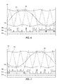
- FIG. 4 is a graphical illustration of first, second, and third sets of carrier and modulation signals, along with shoot-through modulation signals and associated waveforms, generated by the inverter system of FIG. 2 to control the power inverter of FIG. 3 ;
- FIG. 5 is a graphical illustration of the first set of carrier and modulation signals and the associated waveforms of FIG. 4 ;
- FIG. 6 is a graphical illustration of the second set of carrier and modulation signals of FIG. 4 , along with associated waveforms;
- FIG. 7 is a graphical illustration of the third set of carrier and modulation signals of FIG. 4 , along with associated waveforms.
- FIGS. 1-7 are merely illustrative and may not be drawn to scale.
- FIG. 1 to FIG. 7 illustrate a method and system for converting direct current (DC) power to (AC) power.
- a first phase of the AC power is generated based on a first carrier signal.
- a second phase of the AC power is generated based on a second carrier signal.
- the generating of the first phase comprises operating a first set of switches in a power inverter based on the first carrier signal
- the generating of the second phase comprises operating a second set of switches in the power inverter based on the second carrier signal.
- FIG. 1 illustrates a vehicle 10 , or “automobile,” according to one embodiment of the present invention.
- the automobile 10 includes a chassis 12 , a body 14 , four wheels 16 , and an electronic control system (or electronic control unit (ECU)) 18 .
- the body 14 is arranged on the chassis 12 and substantially encloses the other components of the automobile 10 .
- the body 14 and the chassis 12 may jointly form a frame.
- the wheels 16 are each rotationally coupled to the chassis 12 near a respective corner of the body 14 .
- the automobile 10 may be any one of a number of different types of automobiles, such as, for example, a sedan, a wagon, a truck, or a sport utility vehicle (SUV), and may be two-wheel drive (2WD) (i.e., rear-wheel drive or front-wheel drive), four-wheel drive (4WD) or all-wheel drive (AWD).
- 2WD two-wheel drive
- 4WD four-wheel drive
- ATD all-wheel drive
- the vehicle 10 may also incorporate any one of, or combination of, a number of different types of engines (or actuators), such as, for example, a gasoline or diesel fueled combustion engine, a “flex fuel vehicle” (FFV) engine (i.e., using a mixture of gasoline and alcohol), a gaseous compound (e.g., hydrogen and/or natural gas) fueled engine, or a fuel cell, a combustion/electric motor hybrid engine, and an electric motor.
- a gasoline or diesel fueled combustion engine a “flex fuel vehicle” (FFV) engine (i.e., using a mixture of gasoline and alcohol)
- a gaseous compound e.g., hydrogen and/or natural gas
- a fuel cell e.g., hydrogen and/or natural gas
- the automobile 10 is a hybrid vehicle, and further includes an actuator assembly (or powertrain) 20 , a battery 22 , a power inverter (or inverter) 24 , and a radiator 26 .
- the actuator assembly 20 includes an internal combustion engine 28 and an electric motor/generator (or motor) system (or assembly) 30 .
- the electric motor system 30 includes one or more sinusoidally-wound, three-phase alternating current (AC) motor/generators (or motors) (e.g., permanent magnet or induction) such as commonly used in automotive vehicles (e.g., traction drive control systems, and the like).
- AC alternating current
- each of the electric motors includes a stator assembly (including conductive coils), a rotor assembly (including a ferromagnetic core), and a cooling fluid (i.e., coolant).
- the stator assembly and/or the rotor assembly within the electric motors may include multiple (e.g., sixteen) electromagnetic poles, as is commonly understood.
- the combustion engine 28 and the electric motor system 30 are integrated such that both are mechanically coupled to at least some of the wheels 16 through one or more drive shafts 32 .
- the radiator 26 is connected to the frame at an outer portion thereof and although not illustrated in detail, includes multiple cooling channels therethough that contain a cooling fluid (i.e., coolant) such as water and/or ethylene glycol (i.e., “antifreeze”) and is coupled to the engine 28 and the inverter 24 .
- a cooling fluid i.e., coolant
- the inverter 24 receives and shares coolant with the electric motor 30 .
- the radiator 26 may be similarly connected to the inverter 24 and/or the electric motor 30 .
- the electronic control system 18 is in operable communication with the actuator assembly 20 , the battery 22 , and the inverter 24 .
- the electronic control system 18 includes various sensors and automotive control modules, or electronic control units (ECUs), such as an inverter control module and a vehicle controller, and at least one processor and/or a memory which includes instructions stored thereon (or in another computer-readable medium) for carrying out the processes and methods as described below.
- ECUs electronice control units
- a voltage source inverter system (or electric drive system) 34 is shown in accordance with an exemplary embodiment of the present invention.
- the voltage source inverter system 34 includes a controller 36 , the inverter 24 coupled to an output of the controller 36 , the motor 30 coupled to a first output of the inverter 24 , and a modulator 38 having an input coupled to a second output of the inverter 24 and having an output coupled to an input of the controller 36 .
- the controller 36 and the modulator 38 may be integral with the electronic control system 18 shown in FIG. 1 .
- FIG. 3 illustrates the inverter 24 of FIGS. 1 and 2 in greater detail.
- the inverter 24 includes a three-phase circuit coupled to the motor 30 . More specifically, the inverter 24 includes a switch network having a first input coupled to a voltage source V dc (e.g., the battery 22 ) and an output coupled to the motor 30 . Although a single voltage source is shown, a distributed direct current (DC) link with two series sources may be used.
- V dc e.g., the battery 22
- the switch network comprises three pairs (a, b, and c) of series switches with antiparallel diodes (i.e., antiparallel to each switch) corresponding to each of the phases.
- Each of the pairs of series switches comprises a first switch, or transistor, (i.e., a “high” switch) 40 , 42 , and 44 having a first terminal coupled to a positive electrode of the voltage source 22 and a second switch (i.e., a “low” switch) 46 , 48 , and 50 having a second terminal coupled to a negative electrode of the voltage source 22 and having a first terminal coupled to a second terminal of the respective first switch 40 , 42 , and 44 .
- the inverter 24 is a “z-source” inverter, as is commonly understood, and includes an impedance source 52 coupled between the battery 22 and the first, second, and third pairs of switches, which includes an inductive component (or at least one inductor) and a capacitive component (or at least one capacitor).
- the inductive component includes a split inductor having a first inductive portion 54 and a second inductive portion 56 , each of which has first and second sides.
- the first inductive portion 54 is connected between the first switches 40 , 42 , and 44 and the positive electrode of the battery 22 .
- the second inductive portion 56 is connected between the second switches 46 , 48 , and 50 and the negative terminal of the battery 22 .
- the capacitive component includes a first capacitor 58 and a second capacitor 60 connected in an “X” configuration to the first and second inductive portions 54 and 56 . That is, the first capacitor 58 has a first terminal connected to the first side of the first inductive portion 54 and a second terminal connected to the second side of the second inductive portion 56 .
- the second capacitor 60 has a first terminal connected to the second side of the first inductive portion 54 and a second terminal connected to the first side of the second inductive portion 56 .
- the inverter 24 also includes an additional switch 62 , which may be similar to the switches 40 - 50 , and is used to allow a higher voltage to be maintained on inverter side of the DC bus.
- the vehicle 10 is operated by providing power to the wheels 16 with the combustion engine 28 and the electric motor assembly 30 in an alternating manner and/or with the combustion engine 28 and the electric motor assembly 30 simultaneously.
- DC power is provided from the battery 22 to the inverter 24 , which converts the DC power into AC power, before the power is sent to the electric motor 30 .
- the conversion of DC power to AC power is substantially performed by operating (i.e., repeatedly switching) the switches 40 - 50 within the inverter 24 at a “switching frequency,” such as, for example, 12 kilohertz (kHz).
- the controller 36 produces Pulse Width Modulation (PWM) signals for controlling the switching action of the inverter 24 .
- PWM Pulse Width Modulation
- the controller 36 preferably produces continuous PWM (CPWM) signals where each upper and lower switch conducts for a portion of each switching cycle of the inverter 24 .
- the inverter 24 then converts the PWM signals to a modulated voltage waveform for operating the motor 30 .
- FIG. 4 graphically illustrates the PWM signals generated by the controller 36 (and/or the modulator 38 ) for operation of the switches 40 - 50 , in accordance with one embodiment of the present invention.
- the controller 36 (and/or modulator 38 ) generates a first carrier signal 64 , a first modulation signal 66 , a second carrier signal 68 , a second modulation signal 70 , a third carrier signal 72 , and a third modulation signal 74 .
- the controller 36 also generates a high shoot-through modulation signal 76 and a low shoot-through modulation signal 78 .
- each set of a carrier signal and a modulation signal may be combined to generate a “high” waveform 80 and a “low” waveform 82 .
- the waveforms 80 and 82 shown in FIG. 4 correspond to the first carrier signal 64 and the first modulation signal 66 .
- the three separate sets of carrier signals and modulations signals increases the frequency of the ripple current flowing through the inductive component within the inverter 24 , as indicated by the ripple current 84 also represented in FIG. 4 .
- FIGS. 5 , 6 , and 7 graphically illustrate only one set of the carrier and modulation signals in addition to the shoot-through modulation signals 76 and 78 , along with the associated waveforms.
- FIG. 5 shows the first carrier signal 64 and the first modulation signal 66 .
- the high waveform 80 is in a “high” or “on” state when the first modulation signal 66 has an amplitude that is greater than the first carrier signal 64 and/or whenever the first carrier signal 64 passes beyond the shoot-through carrier signals 76 and 78 .
- the high waveform 80 shown in FIG. 5 is used to control the first, or high, switch 40 in the first pair (a) of switches in the inverter 24 .
- the low waveform 82 is in a high or on state when the first modulation signal 66 has an amplitude that is less than the first carrier signal 64 and/or whenever the first carrier signal 64 passes beyond the shoot-through carrier signals 76 and 78 .
- the low waveform 82 shown in FIG. 5 is used to control the second, or low, switch 46 in the first pair (a) of switches in the inverter 24 .
- FIG. 6 shows the second carrier signal 68 and the second modulation signal 70 .
- a high waveform 86 and a low waveform 88 are formed from the second carrier signal 68 and the second modulation signal 70 , along with the shoot-through carrier signals 76 and 78 .
- the high waveform 86 shown in FIG. 6 is used to control the first switch 42 in the second pair (b) of switches in the inverter 24
- the low waveform 88 shown in FIG. 6 is used to control the second switch 48 in the second pair (b) of switches in the inverter 24 .
- FIG. 7 shows the third carrier signal 72 and the third modulation signal 74 .
- a high waveform 90 and a low waveform 92 are formed from the third carrier signal 72 and the third modulation signal 74 , along with the shoot-through carrier signals 76 and 78 .
- the high waveform 90 shown in FIG. 7 is used to control the first switch 44 in the third pair (c) of switches in the inverter 24
- the low waveform 92 shown in FIG. 7 is used to control the second switch 50 in the third pair (c) of switches in the inverter 24 .
- the waveforms 80 , 82 , 86 , 88 , 90 , and 92 determine the output voltages of the different legs of the inverter 24 , and thus the voltages applied across the windings within the motor 30 .
- the operation of the each of the pairs of switches (a, b, and c) generates a respective phase of the AC power sent to the motor 30 .
- the ripple current frequency in the inductive component in the inverter is increased.
- the frequency of the ripple current is tripled (e.g., to 72 kHz) compared to using a single carrier signal for all three phases (24 kHz or twice the carrier frequency of 12 kHz). Therefore, the size of the inductive component within the inverter may be reduced (e.g., to 1 ⁇ 3 of its size when a single carrier signal is used).
- inventions may utilize the method and system described above in implementations other than automobiles, such as watercraft and aircraft.
- the electric motor and the power inverter may have different numbers of phases, such as two or four.
- Other forms of power sources may be used, such as current sources and loads including diode rectifiers, thyristor converters, fuel cells, inductors, capacitors, and/or any combination thereof.
Abstract
Description
Claims (20)
Priority Applications (3)
| Application Number | Priority Date | Filing Date | Title |
|---|---|---|---|
| US11/853,894 US7768228B2 (en) | 2007-09-12 | 2007-09-12 | Method and system for converting DC power to AC power |
| DE102008046301.9A DE102008046301B4 (en) | 2007-09-12 | 2008-09-09 | Method and system for converting DC power to AC power |
| CN2008102159303A CN101388615B (en) | 2007-09-12 | 2008-09-12 | Method and system for converting DC power to AC power |
Applications Claiming Priority (1)
| Application Number | Priority Date | Filing Date | Title |
|---|---|---|---|
| US11/853,894 US7768228B2 (en) | 2007-09-12 | 2007-09-12 | Method and system for converting DC power to AC power |
Publications (2)
| Publication Number | Publication Date |
|---|---|
| US20090066271A1 US20090066271A1 (en) | 2009-03-12 |
| US7768228B2 true US7768228B2 (en) | 2010-08-03 |
Family
ID=40431143
Family Applications (1)
| Application Number | Title | Priority Date | Filing Date |
|---|---|---|---|
| US11/853,894 Expired - Fee Related US7768228B2 (en) | 2007-09-12 | 2007-09-12 | Method and system for converting DC power to AC power |
Country Status (3)
| Country | Link |
|---|---|
| US (1) | US7768228B2 (en) |
| CN (1) | CN101388615B (en) |
| DE (1) | DE102008046301B4 (en) |
Cited By (6)
| Publication number | Priority date | Publication date | Assignee | Title |
|---|---|---|---|---|
| US20100085787A1 (en) * | 2008-10-03 | 2010-04-08 | Ajit Wasant Kane | System and method for powering a hybrid electric vehicle |
| US20120074919A1 (en) * | 2009-06-02 | 2012-03-29 | Toyota Jidosha Kabushiki Kaisha | Power supply system |
| KR101111439B1 (en) | 2010-05-28 | 2012-04-06 | 전남대학교산학협력단 | Control Method for Three-phase Z-Source Inverter |
| KR101192535B1 (en) | 2010-09-30 | 2012-10-17 | 인터실 아메리카스 엘엘씨 | System and method for converting an ac input voltage to a regulated dc output voltage using a z-type converter with rectified switches |
| KR101522414B1 (en) * | 2013-12-31 | 2015-05-21 | 주식회사 효성 | Z-source network apparatus |
| US9428062B2 (en) | 2014-04-23 | 2016-08-30 | GM Global Technology Operations LLC | Duty cycle updates for a power converter |
Families Citing this family (16)
| Publication number | Priority date | Publication date | Assignee | Title |
|---|---|---|---|---|
| BR112012031636A2 (en) * | 2010-06-24 | 2016-11-08 | Mitsubishi Electric Corp | diesel hybrid vehicle system |
| DE102010052808A1 (en) | 2010-11-27 | 2012-05-31 | Daimler Ag | Method for operating vehicle e.g. hybrid vehicle, involves setting switch of one bridge branch of quasi-Z-source inverter such that outputs are shorted together in one time period and not short-circuited in another time period |
| EE05654B1 (en) | 2011-02-28 | 2013-04-15 | Tallinna Tehnikaülikool | Method for Generating Lines with Block-Controlled HV or Multi Phase Impedance, Quasi-Impedance, and Transimpedance |
| US9621073B1 (en) * | 2011-08-31 | 2017-04-11 | The Florida State University Research Foundation, Inc. | 1MHz scalable cascaded Z-source inverter using gallium nitride (GAN) device |
| DE102011086079A1 (en) * | 2011-11-10 | 2013-05-16 | Robert Bosch Gmbh | Method and device for driving an electric machine |
| JP5967702B2 (en) * | 2012-06-01 | 2016-08-10 | 東洋電機製造株式会社 | Power converter |
| JP2014166074A (en) * | 2013-02-26 | 2014-09-08 | Toyota Industries Corp | Drive circuit of magnetless winding field motor |
| KR20150019187A (en) * | 2013-08-13 | 2015-02-25 | 현대모비스 주식회사 | Vehicle Power Supplying Apparatus |
| RU2578042C1 (en) * | 2014-09-19 | 2016-03-20 | Федеральное государственное бюджетное образовательное учреждение высшего профессионального образования "Новосибирский государственный технический университет" | Three phase z-inverter |
| CN104283487A (en) * | 2014-10-28 | 2015-01-14 | 重庆邮电大学 | Novel electric vehicle driving system |
| CN105186909A (en) * | 2015-08-26 | 2015-12-23 | 齐鲁工业大学 | Enhanced Z-source inverter and working method thereof |
| DE102015012343A1 (en) | 2015-09-22 | 2016-04-07 | Daimler Ag | DC voltage conversion device for a motor vehicle and drive train |
| CN106374978A (en) * | 2016-08-29 | 2017-02-01 | 阳光电源股份有限公司 | Power carrier signal coupling circuit and communication system |
| DE102017000396A1 (en) | 2017-01-18 | 2017-07-27 | Daimler Ag | Reduction of voltage losses in a 48V electrical system by means of a voltage converter |
| US10784763B2 (en) | 2017-03-07 | 2020-09-22 | Mediatek Inc. | Dynamic slew rate control |
| TWI678064B (en) * | 2018-03-05 | 2019-11-21 | 聯發科技股份有限公司 | Inverter circuit and method for controlling driver of inverter circuit |
Citations (6)
| Publication number | Priority date | Publication date | Assignee | Title |
|---|---|---|---|---|
| US5103711A (en) * | 1988-03-13 | 1992-04-14 | Casio Computer Co., Ltd. | Musical sound waveform generator having a carrier signal and a modulation signal mixed at a controlled mixing ratio |
| US5142468A (en) * | 1991-05-16 | 1992-08-25 | General Atomics | Power conditioning system for use with two PWM inverters and at least one other load |
| US20030231518A1 (en) * | 2002-06-12 | 2003-12-18 | Peng Fang Z. | Impedance source power converter |
| US20040228150A1 (en) * | 2001-12-20 | 2004-11-18 | Toyota Jidosha Kabushiki Kaisha | Voltage conversion system and method and recording medium |
| US7116012B2 (en) * | 2003-07-30 | 2006-10-03 | General Motors Corporation | Stable power conversion circuits |
| US20070145941A1 (en) * | 2005-12-27 | 2007-06-28 | Matsushita Electric Industrial Co., Ltd. | Motor driving apparatus of washing and drying machine |
Family Cites Families (2)
| Publication number | Priority date | Publication date | Assignee | Title |
|---|---|---|---|---|
| JP4385672B2 (en) * | 2003-08-12 | 2009-12-16 | 株式会社日立製作所 | Power converter using matrix converter |
| US7049778B2 (en) * | 2004-02-09 | 2006-05-23 | Nippon Yusoki Co., Ltd. | Inverter control apparatus and inverter control method |
-
2007
- 2007-09-12 US US11/853,894 patent/US7768228B2/en not_active Expired - Fee Related
-
2008
- 2008-09-09 DE DE102008046301.9A patent/DE102008046301B4/en not_active Expired - Fee Related
- 2008-09-12 CN CN2008102159303A patent/CN101388615B/en not_active Expired - Fee Related
Patent Citations (6)
| Publication number | Priority date | Publication date | Assignee | Title |
|---|---|---|---|---|
| US5103711A (en) * | 1988-03-13 | 1992-04-14 | Casio Computer Co., Ltd. | Musical sound waveform generator having a carrier signal and a modulation signal mixed at a controlled mixing ratio |
| US5142468A (en) * | 1991-05-16 | 1992-08-25 | General Atomics | Power conditioning system for use with two PWM inverters and at least one other load |
| US20040228150A1 (en) * | 2001-12-20 | 2004-11-18 | Toyota Jidosha Kabushiki Kaisha | Voltage conversion system and method and recording medium |
| US20030231518A1 (en) * | 2002-06-12 | 2003-12-18 | Peng Fang Z. | Impedance source power converter |
| US7116012B2 (en) * | 2003-07-30 | 2006-10-03 | General Motors Corporation | Stable power conversion circuits |
| US20070145941A1 (en) * | 2005-12-27 | 2007-06-28 | Matsushita Electric Industrial Co., Ltd. | Motor driving apparatus of washing and drying machine |
Cited By (8)
| Publication number | Priority date | Publication date | Assignee | Title |
|---|---|---|---|---|
| US20100085787A1 (en) * | 2008-10-03 | 2010-04-08 | Ajit Wasant Kane | System and method for powering a hybrid electric vehicle |
| US20120074919A1 (en) * | 2009-06-02 | 2012-03-29 | Toyota Jidosha Kabushiki Kaisha | Power supply system |
| US8773874B2 (en) * | 2009-06-02 | 2014-07-08 | Toyota Jidosha Kabushiki Kaisha | Power supply system and plurality parallel resonant converters having current blocking circuit |
| KR101111439B1 (en) | 2010-05-28 | 2012-04-06 | 전남대학교산학협력단 | Control Method for Three-phase Z-Source Inverter |
| KR101192535B1 (en) | 2010-09-30 | 2012-10-17 | 인터실 아메리카스 엘엘씨 | System and method for converting an ac input voltage to a regulated dc output voltage using a z-type converter with rectified switches |
| KR101522414B1 (en) * | 2013-12-31 | 2015-05-21 | 주식회사 효성 | Z-source network apparatus |
| WO2015102384A1 (en) * | 2013-12-31 | 2015-07-09 | 주식회사 효성 | Z-source circuit apparatus |
| US9428062B2 (en) | 2014-04-23 | 2016-08-30 | GM Global Technology Operations LLC | Duty cycle updates for a power converter |
Also Published As
| Publication number | Publication date |
|---|---|
| DE102008046301B4 (en) | 2014-10-30 |
| US20090066271A1 (en) | 2009-03-12 |
| DE102008046301A1 (en) | 2009-04-30 |
| CN101388615A (en) | 2009-03-18 |
| CN101388615B (en) | 2012-09-05 |
Similar Documents
| Publication | Publication Date | Title |
|---|---|---|
| US7768228B2 (en) | Method and system for converting DC power to AC power | |
| US8115433B2 (en) | Electrical system for pulse-width modulated control of a power inverter using phase-shifted carrier signals and related operating methods | |
| US8054032B2 (en) | Discontinuous pulse width modulation for double-ended inverter system | |
| US7990098B2 (en) | Series-coupled two-motor drive using double-ended inverter system | |
| US7956563B2 (en) | System for using a multi-phase motor with a double-ended inverter system | |
| US7679310B2 (en) | Method and system for controlling pulse width modulation in a power inverter in electric drives | |
| US8002056B2 (en) | Double-ended inverter system with isolated neutral topology | |
| US8476989B2 (en) | Electromagnetic interference filter for automotive electrical systems | |
| US8269434B2 (en) | Electrical system using phase-shifted carrier signals and related operating methods | |
| US8359131B2 (en) | Method and system for operating an electric motor | |
| US7847437B2 (en) | Efficient operating point for double-ended inverter system | |
| US7576500B2 (en) | Method and system for operating a motor to reduce noise in an electric vehicle | |
| US7956569B2 (en) | Double ended inverter system with an impedance source inverter subsystem | |
| US8058830B2 (en) | Charging energy sources with a rectifier using double-ended inverter system | |
| US8319458B2 (en) | Vehicular electrical system and method for controlling an inverter during motor deceleration | |
| US8749090B2 (en) | Dual source automotive propulsion system and method of operation | |
| US8279620B2 (en) | Low inductance power electronics assembly | |
| US8122985B2 (en) | Double-ended inverter drive system for a fuel cell vehicle and related operating method | |
| US8446113B2 (en) | Vehicular electrical system and method for controlling an inverter during motor deceleration | |
| US8624427B2 (en) | Vehicular electrical systems, automotive electrical systems, and automotive propulsion systems | |
| US8354816B2 (en) | Power module layout for automotive power converters | |
| US7924134B2 (en) | Inductor packaging for power converters | |
| US7999503B2 (en) | Control module for dynamic operation of a power inverter using an application specific integrated circuit | |
| US7659684B2 (en) | Method and system for operating a motor to avoid selected pulse ratio values |
Legal Events
| Date | Code | Title | Description |
|---|---|---|---|
| AS | Assignment |
Owner name: GM GLOBAL TECHNOLOGY OPERATIONS, INC, MICHIGAN Free format text: ASSIGNMENT OF ASSIGNORS INTEREST;ASSIGNORS:KAJOUKE, LATEEF A.;WELCHKO, BRIAN A.;REEL/FRAME:019821/0234 Effective date: 20070809 |
|
| AS | Assignment |
Owner name: UNITED STATES DEPARTMENT OF THE TREASURY, DISTRICT Free format text: SECURITY AGREEMENT;ASSIGNOR:GM GLOBAL TECHNOLOGY OPERATIONS, INC.;REEL/FRAME:022195/0334 Effective date: 20081231 Owner name: UNITED STATES DEPARTMENT OF THE TREASURY,DISTRICT Free format text: SECURITY AGREEMENT;ASSIGNOR:GM GLOBAL TECHNOLOGY OPERATIONS, INC.;REEL/FRAME:022195/0334 Effective date: 20081231 |
|
| AS | Assignment |
Owner name: CITICORP USA, INC. AS AGENT FOR BANK PRIORITY SECU Free format text: SECURITY AGREEMENT;ASSIGNOR:GM GLOBAL TECHNOLOGY OPERATIONS, INC.;REEL/FRAME:022554/0479 Effective date: 20090409 Owner name: CITICORP USA, INC. AS AGENT FOR HEDGE PRIORITY SEC Free format text: SECURITY AGREEMENT;ASSIGNOR:GM GLOBAL TECHNOLOGY OPERATIONS, INC.;REEL/FRAME:022554/0479 Effective date: 20090409 |
|
| AS | Assignment |
Owner name: GM GLOBAL TECHNOLOGY OPERATIONS, INC., MICHIGAN Free format text: RELEASE BY SECURED PARTY;ASSIGNOR:UNITED STATES DEPARTMENT OF THE TREASURY;REEL/FRAME:023124/0670 Effective date: 20090709 Owner name: GM GLOBAL TECHNOLOGY OPERATIONS, INC.,MICHIGAN Free format text: RELEASE BY SECURED PARTY;ASSIGNOR:UNITED STATES DEPARTMENT OF THE TREASURY;REEL/FRAME:023124/0670 Effective date: 20090709 |
|
| AS | Assignment |
Owner name: GM GLOBAL TECHNOLOGY OPERATIONS, INC., MICHIGAN Free format text: RELEASE BY SECURED PARTY;ASSIGNORS:CITICORP USA, INC. AS AGENT FOR BANK PRIORITY SECURED PARTIES;CITICORP USA, INC. AS AGENT FOR HEDGE PRIORITY SECURED PARTIES;REEL/FRAME:023155/0880 Effective date: 20090814 Owner name: GM GLOBAL TECHNOLOGY OPERATIONS, INC.,MICHIGAN Free format text: RELEASE BY SECURED PARTY;ASSIGNORS:CITICORP USA, INC. AS AGENT FOR BANK PRIORITY SECURED PARTIES;CITICORP USA, INC. AS AGENT FOR HEDGE PRIORITY SECURED PARTIES;REEL/FRAME:023155/0880 Effective date: 20090814 |
|
| AS | Assignment |
Owner name: UNITED STATES DEPARTMENT OF THE TREASURY, DISTRICT Free format text: SECURITY AGREEMENT;ASSIGNOR:GM GLOBAL TECHNOLOGY OPERATIONS, INC.;REEL/FRAME:023156/0215 Effective date: 20090710 Owner name: UNITED STATES DEPARTMENT OF THE TREASURY,DISTRICT Free format text: SECURITY AGREEMENT;ASSIGNOR:GM GLOBAL TECHNOLOGY OPERATIONS, INC.;REEL/FRAME:023156/0215 Effective date: 20090710 |
|
| AS | Assignment |
Owner name: UAW RETIREE MEDICAL BENEFITS TRUST, MICHIGAN Free format text: SECURITY AGREEMENT;ASSIGNOR:GM GLOBAL TECHNOLOGY OPERATIONS, INC.;REEL/FRAME:023162/0187 Effective date: 20090710 Owner name: UAW RETIREE MEDICAL BENEFITS TRUST,MICHIGAN Free format text: SECURITY AGREEMENT;ASSIGNOR:GM GLOBAL TECHNOLOGY OPERATIONS, INC.;REEL/FRAME:023162/0187 Effective date: 20090710 |
|
| FEPP | Fee payment procedure |
Free format text: PAYOR NUMBER ASSIGNED (ORIGINAL EVENT CODE: ASPN); ENTITY STATUS OF PATENT OWNER: LARGE ENTITY |
|
| STCF | Information on status: patent grant |
Free format text: PATENTED CASE |
|
| AS | Assignment |
Owner name: GM GLOBAL TECHNOLOGY OPERATIONS, INC., MICHIGAN Free format text: RELEASE BY SECURED PARTY;ASSIGNOR:UNITED STATES DEPARTMENT OF THE TREASURY;REEL/FRAME:025245/0780 Effective date: 20100420 |
|
| AS | Assignment |
Owner name: GM GLOBAL TECHNOLOGY OPERATIONS, INC., MICHIGAN Free format text: RELEASE BY SECURED PARTY;ASSIGNOR:UAW RETIREE MEDICAL BENEFITS TRUST;REEL/FRAME:025314/0946 Effective date: 20101026 |
|
| AS | Assignment |
Owner name: WILMINGTON TRUST COMPANY, DELAWARE Free format text: SECURITY AGREEMENT;ASSIGNOR:GM GLOBAL TECHNOLOGY OPERATIONS, INC.;REEL/FRAME:025324/0057 Effective date: 20101027 |
|
| AS | Assignment |
Owner name: GM GLOBAL TECHNOLOGY OPERATIONS LLC, MICHIGAN Free format text: CHANGE OF NAME;ASSIGNOR:GM GLOBAL TECHNOLOGY OPERATIONS, INC.;REEL/FRAME:025781/0035 Effective date: 20101202 |
|
| FPAY | Fee payment |
Year of fee payment: 4 |
|
| AS | Assignment |
Owner name: GM GLOBAL TECHNOLOGY OPERATIONS LLC, MICHIGAN Free format text: RELEASE BY SECURED PARTY;ASSIGNOR:WILMINGTON TRUST COMPANY;REEL/FRAME:034185/0587 Effective date: 20141017 |
|
| MAFP | Maintenance fee payment |
Free format text: PAYMENT OF MAINTENANCE FEE, 8TH YEAR, LARGE ENTITY (ORIGINAL EVENT CODE: M1552) Year of fee payment: 8 |
|
| FEPP | Fee payment procedure |
Free format text: MAINTENANCE FEE REMINDER MAILED (ORIGINAL EVENT CODE: REM.); ENTITY STATUS OF PATENT OWNER: LARGE ENTITY |
|
| LAPS | Lapse for failure to pay maintenance fees |
Free format text: PATENT EXPIRED FOR FAILURE TO PAY MAINTENANCE FEES (ORIGINAL EVENT CODE: EXP.); ENTITY STATUS OF PATENT OWNER: LARGE ENTITY |
|
| STCH | Information on status: patent discontinuation |
Free format text: PATENT EXPIRED DUE TO NONPAYMENT OF MAINTENANCE FEES UNDER 37 CFR 1.362 |
|
| FP | Lapsed due to failure to pay maintenance fee |
Effective date: 20220803 |