US7268325B1 - Method of making flexible sheet heater - Google Patents
Method of making flexible sheet heater Download PDFInfo
- Publication number
- US7268325B1 US7268325B1 US11/584,567 US58456706A US7268325B1 US 7268325 B1 US7268325 B1 US 7268325B1 US 58456706 A US58456706 A US 58456706A US 7268325 B1 US7268325 B1 US 7268325B1
- Authority
- US
- United States
- Prior art keywords
- electrically conductive
- heating element
- conductive fabric
- pet film
- fabric
- Prior art date
- Legal status (The legal status is an assumption and is not a legal conclusion. Google has not performed a legal analysis and makes no representation as to the accuracy of the status listed.)
- Active
Links
Images


Classifications
-
- H—ELECTRICITY
- H05—ELECTRIC TECHNIQUES NOT OTHERWISE PROVIDED FOR
- H05B—ELECTRIC HEATING; ELECTRIC LIGHT SOURCES NOT OTHERWISE PROVIDED FOR; CIRCUIT ARRANGEMENTS FOR ELECTRIC LIGHT SOURCES, IN GENERAL
- H05B3/00—Ohmic-resistance heating
- H05B3/20—Heating elements having extended surface area substantially in a two-dimensional plane, e.g. plate-heater
- H05B3/34—Heating elements having extended surface area substantially in a two-dimensional plane, e.g. plate-heater flexible, e.g. heating nets or webs
- H05B3/36—Heating elements having extended surface area substantially in a two-dimensional plane, e.g. plate-heater flexible, e.g. heating nets or webs heating conductor embedded in insulating material
-
- H—ELECTRICITY
- H01—ELECTRIC ELEMENTS
- H01C—RESISTORS
- H01C17/00—Apparatus or processes specially adapted for manufacturing resistors
- H01C17/06—Apparatus or processes specially adapted for manufacturing resistors adapted for coating resistive material on a base
- H01C17/07—Apparatus or processes specially adapted for manufacturing resistors adapted for coating resistive material on a base by resistor foil bonding, e.g. cladding
-
- H—ELECTRICITY
- H01—ELECTRIC ELEMENTS
- H01C—RESISTORS
- H01C3/00—Non-adjustable metal resistors made of wire or ribbon, e.g. coiled, woven or formed as grids
- H01C3/10—Non-adjustable metal resistors made of wire or ribbon, e.g. coiled, woven or formed as grids the resistive element having zig-zag or sinusoidal configuration
- H01C3/12—Non-adjustable metal resistors made of wire or ribbon, e.g. coiled, woven or formed as grids the resistive element having zig-zag or sinusoidal configuration lying in one plane
-
- H—ELECTRICITY
- H05—ELECTRIC TECHNIQUES NOT OTHERWISE PROVIDED FOR
- H05B—ELECTRIC HEATING; ELECTRIC LIGHT SOURCES NOT OTHERWISE PROVIDED FOR; CIRCUIT ARRANGEMENTS FOR ELECTRIC LIGHT SOURCES, IN GENERAL
- H05B2203/00—Aspects relating to Ohmic resistive heating covered by group H05B3/00
- H05B2203/002—Heaters using a particular layout for the resistive material or resistive elements
- H05B2203/003—Heaters using a particular layout for the resistive material or resistive elements using serpentine layout
-
- H—ELECTRICITY
- H05—ELECTRIC TECHNIQUES NOT OTHERWISE PROVIDED FOR
- H05B—ELECTRIC HEATING; ELECTRIC LIGHT SOURCES NOT OTHERWISE PROVIDED FOR; CIRCUIT ARRANGEMENTS FOR ELECTRIC LIGHT SOURCES, IN GENERAL
- H05B2203/00—Aspects relating to Ohmic resistive heating covered by group H05B3/00
- H05B2203/017—Manufacturing methods or apparatus for heaters
-
- H—ELECTRICITY
- H05—ELECTRIC TECHNIQUES NOT OTHERWISE PROVIDED FOR
- H05B—ELECTRIC HEATING; ELECTRIC LIGHT SOURCES NOT OTHERWISE PROVIDED FOR; CIRCUIT ARRANGEMENTS FOR ELECTRIC LIGHT SOURCES, IN GENERAL
- H05B2203/00—Aspects relating to Ohmic resistive heating covered by group H05B3/00
- H05B2203/036—Heaters specially adapted for garment heating
Definitions
- the present invention relates to a method of making a flexible sheet heater for use in waist pads, waist bandages, and clothes and more particularly, to a method of making a flexible sheet heater by using an electrically conductive fabric.
- Flexible, electrically conductive sheet heaters are intensively used in clothes, kneepads, gloves, shoe pads, ear covers, waist pads, and etc. to keep the user warm.
- a conventional flexible, electrically conductive sheet heater comprising two flexible heat-resistant insulative sheets, a metal loop formed of a thin metal sheet member by chemical etching or stamping and sandwiched in between the two flexible heat-resistant insulative sheets, and two electrical terminals respectively connected to the two distal ends of the metal loop and extending out of the two flexible heat-resistant insulative sheets for enabling an electric current to be transmitted through the metal loop to generate heat.
- the aforesaid two different electrically conductive sheet heaters have light and thin characteristics and can be slightly curved; however, they cannot be folded up. Because the aforesaid two different electrically conductive heater systems are not foldable, their application is limited.
- a flexible, electrically conductive sheet heater which has an electrically conductive fabric, for example a carbon fiber fabric, sandwiched in between two flexible heat-resistant insulative coverings and provided with a power input structure.
- This design of flexible, electrically conductive sheet heaters has light and thin characteristics and is foldable for different applications. Exemplars of these electrically conductive fabric-based heater designs are seen in Taiwan Patent Publication No. 374,539, U.S. Pat. No. 6,172,344, and U.S. Pat. No. 6,483,087.
- the heater comprises an electrically conductive rectangular carbon fiber fabric, two elongated conductive copper strips respectively affixed to two sides of the carbon fiber fabric, two electric wires respectively connected to the copper strips, and two plastic cover films respectively covered on the top and bottom sides of the carbon fiber fabric and the copper strips.
- the conductivity of the copper strips is superior to the carbon fiber fabric, resulting in a high contact resistance between the two copper strips and the carbon fiber fabric.
- the surface of the carbon fiber fabric is not a smooth surface such that the whole surface of each copper strip is not fully kept in contact with the carbon fiber fabric, an excessive high temperature may be produced between the copper strips and the carbon fiber fabric.
- Taiwan Patent Publication No. 374,539 does no provide any measures to eliminate the aforesaid problems.
- U.S. Pat. No. 6,172,344 discloses continuous and batch-based conductive element fabrication methods by sandwiching a carbonized fabric with electrical terminals between layers of plastic insulating material.
- U.S. Pat. No. 6,172,344 does not teach the way of keeping the carbonized fabric between the two layers of plastic insulating material in a smooth manner.
- U.S. Pat. No. 6,483,087 discloses a process of making a heater by: combining a layer of electrically conductive fabric with two metal foil bus bars, securing the bus bars to the conductive fabric, drawing the conductive fabric layer containing bus bars between two layers of thermoplastic film forming a sandwich structure, feeding the sandwich structure through a pinch roller preheated at a predetermined temperature and thickness to cause gelling of the thermoplastic layers, and consolidating the conductive fiber layer to form a single sheet heater. According to this method, it is difficult to cut the layer of electrically conductive fabric into the desired curved shape. When cutting the layer of electrically conductive fabric, the carbonized fiber structure of the layer of electrically conductive fabric tends to be stretched and damaged, and the layer of electrically conductive fabric may be deformed easily when pulled toward the layers of thermoplastic film.
- the present invention has been accomplished under the circumstances in view. It is therefore one object of the present invention to provide a method of making a flexible sheet heater, which enables an electrically conductive fabric to be rapidly and smoothly sandwiched in between two protective sheet members.
- the method of making a flexible sheet heater comprises the steps of: a) preparing an electrically conductive fabric; b) preparing a support member having a PET (polyethylene terephthalate) film and a layer of acrylic glue covered on one side of the PET film; c) joining the electrically conductive fabric and the support member together by adhering the layer of acrylic glue to one side of the electrically conductive fabric through a pressing process; d) cutting the electrically conductive fabric to form a heating element having a predetermined loop pattern by a stamping process; e) applying a conducting glue to each of two distal ends of the heating element and fixedly bonding a respective electrical terminal to the conducting glue at each of the two distal ends of the heating element; f) bonding a first flexible protective sheet member to one side of the heating element opposite to the PET film through a hot press; g) removing the PET film from the heating element; and h) bonding a second flexible protective sheet member to one side of the heating element opposite
- FIG. 1 is a flow chart showing the steps of the method of making a flexible sheet heater according to a preferred embodiment of the present invention.
- FIG. 2 is a sectional view of a part of a support member prepared in step b) of the method of making the flexible sheet heater according to the preferred embodiment of the present invention.
- FIGS. 3A and 3B are schematic drawings showing the performance of step c) of the method of making the flexible sheet heater according to the preferred embodiment of the present invention.
- FIGS. 4A and 4B are schematic drawings showing the performance of step d) of the method of making the flexible sheet heater according to the preferred embodiment of the present invention.
- FIG. 5 illustrates the product obtained after step e) of the method of making the flexible sheet heater according to the preferred embodiment of the present invention.
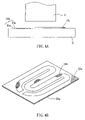
- FIGS. 6A and 6B are schematic drawings showing the performance of step f) of the method of making the flexible sheet heater according to the preferred embodiment of the present invention.
- FIG. 7 illustrates the product obtained after step g) of the method of making the flexible sheet heater according to the preferred embodiment of the present invention.
- FIGS. 8A and 8B are schematic drawings showing the performance of step h) of the method of making the flexible sheet heater according to the preferred embodiment of the present invention.
- the method of making a flexible sheet heater in accordance with a preferred embodiment of the present invention comprises the following steps.
- the electrically conductive fabric is a roll of carbon fiber fabric.
- the support member 20 is a roll of member comprising a polyethylene terephthalate (PET) film 21 and a layer of acrylic glue 22 covered on one side of the PET film 21 .
- PET polyethylene terephthalate
- the electrically conductive fabric 10 and the support member 20 are delivered along a predetermined path through the gap in between two rollers A for enabling the acrylic glue 22 at one side of the PET film 21 of the support member 20 to be bonded to one side of the electrically conductive fabric 10 so that the electrically conductive fabric 10 and the support member 20 are joined together and rolled up, thereby forming a roll of synthetic sheet member 30 , which is then properly cut into a substrate 30 a , as shown in FIG. 3B , subject to a predetermined shape and size for further processing.
- the substrate 30 a is put on the worktable B of a stamping press with the electrically conductive fabric 10 a facing the cutter C of the stamping press, and then the stamping press is operated to stamp the cutter C against the electrically conductive fabric 10 a without touching the PET film 21 a of the support member 20 a of the substrate 30 a so as to cut the electrically conductive fabric 10 a into a heating element 10 b having two distal ends subject to a predetermined loop pattern.
- the PET film 21 a gives a support to the electrically conductive fabric 10 a , so that the interlacing fiber structure of the electrically conductive fabric 10 a does not disperse and the loop pattern of the heating element 10 b is well kept in shape when the electrically conductive fabric 10 a is cut and stretched by the cutter C.
- the first flexible protective sheet member 60 is formed of a waterproof fabric layer 61 and a thermoplastic layer 62 bonded to one side of the heating element 10 b opposite to the PET film 21 a by a hot press, as shown in FIGS. 6A and 6B .
- the waterproof fabric layer 61 can be formed of natural or synthetic fibers or other material such as glass fiber or metal, and the thermoplastic layer 62 can be formed of nylon, polyurethane, polyvinyl chloride or polyester.
- the invention uses the support member 20 a to support the electrically conductive fabric 10 a for processing, the interlacing fiber structure of the electrically conductive fabric 10 a does not disperse and the loop pattern of the heating element 10 b is well kept in shape when the electrically conductive fabric 10 a is cut and stretched by the cutter during the stamping operation. More particularly, the support member 20 a of the invention uses the PET film 21 a and the acrylic glue 22 a as elements thereof, no residual acrylic glue will be left on the heating element 10 b after removing of the PET film 21 a from the heating element 10 b.
- the heating element 10 b can be smoothly adhered to and supported on the first flexible protective sheet member 60 so that the heating element 10 b can further be smoothly sandwiched in between the first flexible protective sheet member 60 and the second flexible protective sheet member 70 .
Landscapes
- Engineering & Computer Science (AREA)
- Microelectronics & Electronic Packaging (AREA)
- Manufacturing & Machinery (AREA)
- Surface Heating Bodies (AREA)
Abstract
A method of making a flexible sheet heater includes the steps of (i) bonding an electrically conductive fabric and an support member formed of a PET film and a layer of acrylic together, ii) stamp-cutting the electrically conductive fabric to form a heating element having a predetermined loop, iii) attaching two electrical terminals to two distal ends of the heating element respectively, iv) bonding a first flexible protective sheet member to one side of the heating element opposite to the PET film, v) removing the PET film from the heating element; and vi) bonding a second flexible protective sheet member to the other side of the heating element opposite to the first flexible protective sheet member so that the heating element is sandwiched between the first and second flexible protective sheet members.
Description
1. Field of the Invention
The present invention relates to a method of making a flexible sheet heater for use in waist pads, waist bandages, and clothes and more particularly, to a method of making a flexible sheet heater by using an electrically conductive fabric.
2. Description of the Related Art
Flexible, electrically conductive sheet heaters are intensively used in clothes, kneepads, gloves, shoe pads, ear covers, waist pads, and etc. to keep the user warm.
A conventional flexible, electrically conductive sheet heater is known comprising two flexible heat-resistant insulative sheets, a metal loop formed of a thin metal sheet member by chemical etching or stamping and sandwiched in between the two flexible heat-resistant insulative sheets, and two electrical terminals respectively connected to the two distal ends of the metal loop and extending out of the two flexible heat-resistant insulative sheets for enabling an electric current to be transmitted through the metal loop to generate heat. There is known another conventional structure of flexible, electrically conductive sheet heater, which comprises a first flexible heat-resistant insulative sheet, a carbon loop printed on the first flexible heat-resistant insulative sheet, a second flexible heat-resistant insulative sheet bonded to the first flexible heat-resistant insulative sheet to have the carbon loop be sandwiched in between the two flexible heat-resistant insulative sheets, and two electrical terminals respectively connected to the two distal ends of the carbon loop and extending out of the two flexible heat-resistant insulative sheets.
The aforesaid two different electrically conductive sheet heaters have light and thin characteristics and can be slightly curved; however, they cannot be folded up. Because the aforesaid two different electrically conductive heater systems are not foldable, their application is limited.
There is also known a flexible, electrically conductive sheet heater, which has an electrically conductive fabric, for example a carbon fiber fabric, sandwiched in between two flexible heat-resistant insulative coverings and provided with a power input structure. This design of flexible, electrically conductive sheet heaters has light and thin characteristics and is foldable for different applications. Exemplars of these electrically conductive fabric-based heater designs are seen in Taiwan Patent Publication No. 374,539, U.S. Pat. No. 6,172,344, and U.S. Pat. No. 6,483,087.
According to Taiwan Patent Publication No. 374,539, the heater comprises an electrically conductive rectangular carbon fiber fabric, two elongated conductive copper strips respectively affixed to two sides of the carbon fiber fabric, two electric wires respectively connected to the copper strips, and two plastic cover films respectively covered on the top and bottom sides of the carbon fiber fabric and the copper strips. According to this design, the conductivity of the copper strips is superior to the carbon fiber fabric, resulting in a high contact resistance between the two copper strips and the carbon fiber fabric. Further, because the surface of the carbon fiber fabric is not a smooth surface such that the whole surface of each copper strip is not fully kept in contact with the carbon fiber fabric, an excessive high temperature may be produced between the copper strips and the carbon fiber fabric. Taiwan Patent Publication No. 374,539 does no provide any measures to eliminate the aforesaid problems.
U.S. Pat. No. 6,172,344 discloses continuous and batch-based conductive element fabrication methods by sandwiching a carbonized fabric with electrical terminals between layers of plastic insulating material. However, U.S. Pat. No. 6,172,344 does not teach the way of keeping the carbonized fabric between the two layers of plastic insulating material in a smooth manner.
U.S. Pat. No. 6,483,087 discloses a process of making a heater by: combining a layer of electrically conductive fabric with two metal foil bus bars, securing the bus bars to the conductive fabric, drawing the conductive fabric layer containing bus bars between two layers of thermoplastic film forming a sandwich structure, feeding the sandwich structure through a pinch roller preheated at a predetermined temperature and thickness to cause gelling of the thermoplastic layers, and consolidating the conductive fiber layer to form a single sheet heater. According to this method, it is difficult to cut the layer of electrically conductive fabric into the desired curved shape. When cutting the layer of electrically conductive fabric, the carbonized fiber structure of the layer of electrically conductive fabric tends to be stretched and damaged, and the layer of electrically conductive fabric may be deformed easily when pulled toward the layers of thermoplastic film.
The present invention has been accomplished under the circumstances in view. It is therefore one object of the present invention to provide a method of making a flexible sheet heater, which enables an electrically conductive fabric to be rapidly and smoothly sandwiched in between two protective sheet members.
To achieve this object of the present invention, the method of making a flexible sheet heater comprises the steps of: a) preparing an electrically conductive fabric; b) preparing a support member having a PET (polyethylene terephthalate) film and a layer of acrylic glue covered on one side of the PET film; c) joining the electrically conductive fabric and the support member together by adhering the layer of acrylic glue to one side of the electrically conductive fabric through a pressing process; d) cutting the electrically conductive fabric to form a heating element having a predetermined loop pattern by a stamping process; e) applying a conducting glue to each of two distal ends of the heating element and fixedly bonding a respective electrical terminal to the conducting glue at each of the two distal ends of the heating element; f) bonding a first flexible protective sheet member to one side of the heating element opposite to the PET film through a hot press; g) removing the PET film from the heating element; and h) bonding a second flexible protective sheet member to one side of the heating element opposite to the first flexible protective sheet member such that the heating element is sandwiched between the first and second flexible protective sheet members.
Referring to FIG. 1 , the method of making a flexible sheet heater in accordance with a preferred embodiment of the present invention comprises the following steps.
a) Prepare an electrically conductive fabric 10. As shown in FIG. 3A , the electrically conductive fabric is a roll of carbon fiber fabric.
b) Prepare a support member 20. As shown in FIGS. 2 and 3A , the support member 20 is a roll of member comprising a polyethylene terephthalate (PET) film 21 and a layer of acrylic glue 22 covered on one side of the PET film 21.
c) Join the electrically conductive fabric 10 and the support member 20 together. As shown in FIG. 3A , the electrically conductive fabric 10 and the support member 20 are delivered along a predetermined path through the gap in between two rollers A for enabling the acrylic glue 22 at one side of the PET film 21 of the support member 20 to be bonded to one side of the electrically conductive fabric 10 so that the electrically conductive fabric 10 and the support member 20 are joined together and rolled up, thereby forming a roll of synthetic sheet member 30, which is then properly cut into a substrate 30 a, as shown in FIG. 3B , subject to a predetermined shape and size for further processing.
d) Stamp the electrically conductive fabric 10 a of the substrate 30 a subject to a predetermined loop pattern, thereby forming a heating element 10 b on the support member 20 a of the substrate 30 a. As shown in FIGS. 4A-4B , the substrate 30 a is put on the worktable B of a stamping press with the electrically conductive fabric 10 a facing the cutter C of the stamping press, and then the stamping press is operated to stamp the cutter C against the electrically conductive fabric 10 a without touching the PET film 21 a of the support member 20 a of the substrate 30 a so as to cut the electrically conductive fabric 10 a into a heating element 10 b having two distal ends subject to a predetermined loop pattern. Because the electrically conductive fabric 10 a is bonded to the PET film 21 a, the PET film 21 a gives a support to the electrically conductive fabric 10 a, so that the interlacing fiber structure of the electrically conductive fabric 10 a does not disperse and the loop pattern of the heating element 10 b is well kept in shape when the electrically conductive fabric 10 a is cut and stretched by the cutter C.
e) Apply a conducting glue 40 to each of the two distal ends of the heating element 10 b and fixedly bond a respective electrical terminal 50 to the conducting glue 40 at each of the two distal ends of the heating element 10 b as shown in FIG. 5 .
f) Bond a first flexible protective sheet member 60 to one side of the heating element 10 b opposite to the PET film 21 a. The first flexible protective sheet member 60 is formed of a waterproof fabric layer 61 and a thermoplastic layer 62 bonded to one side of the heating element 10 b opposite to the PET film 21 a by a hot press, as shown in FIGS. 6A and 6B . The waterproof fabric layer 61 can be formed of natural or synthetic fibers or other material such as glass fiber or metal, and the thermoplastic layer 62 can be formed of nylon, polyurethane, polyvinyl chloride or polyester.
g) Remove the PET film 21 a from the heating element 10 b as shown in FIG. 7 . When the PET film 21 a is removed from the heating element 10 b, the acrylic glue 22 a is separated with the PET film 21 a from the heating element 10 b without leaving any residue at the heating element 10 b due to the acrylic material property.
h) Bond a second flexible protective sheet member 70 to the other side of the heating element 10 b opposite to the first flexible protective sheet member 60. As shown in FIGS. 8A and 8B , the second flexible protective sheet member 70 of same structure as the first flexible protective sheet member 60 is bonded to the other side of the heating element 10 b opposite to the first flexible protective sheet member 60 by a hot press to have the thermoplastic layer 62 of the first flexible protective sheet member 60 and the thermoplastic layer of the second flexible protective sheet member 70 be bonded together, thereby forming the desired flexible sheet heater 1.
Because the invention uses the support member 20 a to support the electrically conductive fabric 10 a for processing, the interlacing fiber structure of the electrically conductive fabric 10 a does not disperse and the loop pattern of the heating element 10 b is well kept in shape when the electrically conductive fabric 10 a is cut and stretched by the cutter during the stamping operation. More particularly, the support member 20 a of the invention uses the PET film 21 a and the acrylic glue 22 a as elements thereof, no residual acrylic glue will be left on the heating element 10 b after removing of the PET film 21 a from the heating element 10 b.
Further, by means of the support of the support member 20 a, the heating element 10 b can be smoothly adhered to and supported on the first flexible protective sheet member 60 so that the heating element 10 b can further be smoothly sandwiched in between the first flexible protective sheet member 60 and the second flexible protective sheet member 70.
Claims (5)
1. A method of making a flexible sheet heater comprising the steps of:
a) preparing an electrically conductive fabric;
b) preparing a support member having a PET film and a layer of acrylic glue covered on one side of said PET film;
c) joining said electrically conductive fabric and said support member together by adhering said layer of acrylic glue to one side of said electrically conductive fabric by pressure;
d) cutting said electrically conductive fabric to form a heating element having a predetermined loop pattern by a stamping process;
e) applying a conducting glue to each of two distal ends of said heating element and fixedly bonding a respective electrical terminal to the conducting glue at each of the two distal ends of said heating element;
f) bonding a first flexible protective sheet member to one side of said heating element opposite to said PET film through a hot press;
g) removing said PET film from said heating element; and
h) bonding a second flexible protective sheet member to one side of said heating element opposite to said first flexible protective sheet member.
2. The method as claimed in claim 1 , wherein said electrically conductive fabric is a carbon fiber fabric.
3. The method as claimed in claim 1 , wherein the electrically conductive fabric prepared in step a) is a roll of carbon fiber fabric; the support member prepared in step b) is a roll of PET film covered with a layer of acrylic glue on one side thereof; said step c) joining said electrically conductive fabric and said support member together is performed in such a manner that said electrically conductive fabric and said support member are delivered along a predetermined path through the gap in between two rollers for enabling the acrylic glue at one side of the PET film of said support member to be bonded to one side of said electrically conductive fabric so that said electrically conductive fabric and said support member are joined together and rolled up, thereby forming a roll of synthetic sheet member, which is then cut into a substrate subject to a predetermined shape and size for further processing in said step d).
4. The method as claimed in claim 1 , wherein said first flexible protective sheet member is formed of a waterproof fabric layer and a thermoplastic layer covered on one side of said waterproof fabric layer for bonding to one side of said heating element opposite to said PET film.
5. The method as claimed in claim 4 , wherein said second flexible protective sheet member is formed of a waterproof fabric layer and a thermoplastic layer covered on one side of said waterproof fabric layer for bonding to one side of said heating element opposite to said first flexible protective sheet member.
Priority Applications (1)
| Application Number | Priority Date | Filing Date | Title |
|---|---|---|---|
| US11/584,567 US7268325B1 (en) | 2006-10-23 | 2006-10-23 | Method of making flexible sheet heater |
Applications Claiming Priority (1)
| Application Number | Priority Date | Filing Date | Title |
|---|---|---|---|
| US11/584,567 US7268325B1 (en) | 2006-10-23 | 2006-10-23 | Method of making flexible sheet heater |
Publications (1)
| Publication Number | Publication Date |
|---|---|
| US7268325B1 true US7268325B1 (en) | 2007-09-11 |
Family
ID=38473233
Family Applications (1)
| Application Number | Title | Priority Date | Filing Date |
|---|---|---|---|
| US11/584,567 Active US7268325B1 (en) | 2006-10-23 | 2006-10-23 | Method of making flexible sheet heater |
Country Status (1)
| Country | Link |
|---|---|
| US (1) | US7268325B1 (en) |
Cited By (11)
| Publication number | Priority date | Publication date | Assignee | Title |
|---|---|---|---|---|
| WO2008138960A1 (en) * | 2007-05-16 | 2008-11-20 | Inergy Automotive Systems Research (Société Anonyme) | Urea tank and base plate with an integrated heating element |
| US20100200485A1 (en) * | 2005-08-16 | 2010-08-12 | Alberto Parra Navarrete | Filter device with a heater |
| US20120228280A1 (en) * | 2009-11-05 | 2012-09-13 | Richard Dod Coates | Heating panel and method therefor |
| US20130068753A1 (en) * | 2011-09-21 | 2013-03-21 | Chung-Yeng Lin | Electrothermal article with a foldable structure |
| US20160163415A1 (en) * | 2014-12-04 | 2016-06-09 | Wicetec Oy | Conductor Joint and Conductor Joint Component |
| US20160183359A1 (en) * | 2014-12-22 | 2016-06-23 | Alt Technologies B.V. | Flexible electrical conductor device |
| WO2020174000A1 (en) * | 2019-02-26 | 2020-09-03 | Iee International Electronics & Engineering S.A. | Flexible and stretchable electric heater based on electrically conductive textile material and method of manufacturing same |
| LU101201B1 (en) * | 2019-04-30 | 2020-10-30 | Iee Sa | Flexible and Stretchable Electric Heater based on Electrically Conductive Textile Material and Method of Manufacturing Same |
| US10841980B2 (en) | 2015-10-19 | 2020-11-17 | Laminaheat Holding Ltd. | Laminar heating elements with customized or non-uniform resistance and/or irregular shapes and processes for manufacture |
| US10925119B2 (en) | 2015-01-12 | 2021-02-16 | Laminaheat Holding Ltd. | Fabric heating element |
| USD911038S1 (en) | 2019-10-11 | 2021-02-23 | Laminaheat Holding Ltd. | Heating element sheet having perforations |
Citations (2)
| Publication number | Priority date | Publication date | Assignee | Title |
|---|---|---|---|---|
| US6172344B1 (en) | 1993-12-24 | 2001-01-09 | Gorix Limited | Electrically conductive materials |
| US6483087B2 (en) | 1999-12-10 | 2002-11-19 | Thermion Systems International | Thermoplastic laminate fabric heater and methods for making same |
-
2006
- 2006-10-23 US US11/584,567 patent/US7268325B1/en active Active
Patent Citations (2)
| Publication number | Priority date | Publication date | Assignee | Title |
|---|---|---|---|---|
| US6172344B1 (en) | 1993-12-24 | 2001-01-09 | Gorix Limited | Electrically conductive materials |
| US6483087B2 (en) | 1999-12-10 | 2002-11-19 | Thermion Systems International | Thermoplastic laminate fabric heater and methods for making same |
Cited By (22)
| Publication number | Priority date | Publication date | Assignee | Title |
|---|---|---|---|---|
| US20100200485A1 (en) * | 2005-08-16 | 2010-08-12 | Alberto Parra Navarrete | Filter device with a heater |
| US8282819B2 (en) * | 2005-08-16 | 2012-10-09 | Robert Bosch Gmbh | Filter device with a heater |
| EP3301272A1 (en) | 2007-05-16 | 2018-04-04 | Plastic Omnium Advanced Innovation and Research | Urea tank and base plate with an integrated heating element |
| US20100220984A1 (en) * | 2007-05-16 | 2010-09-02 | Inergy Automotive Systems Research (Societe Anonym | Urea tank and base plate with an integrated heating element |
| WO2008138960A1 (en) * | 2007-05-16 | 2008-11-20 | Inergy Automotive Systems Research (Société Anonyme) | Urea tank and base plate with an integrated heating element |
| US8625978B2 (en) | 2007-05-16 | 2014-01-07 | Inergy Automotive Systems Research (Societe Anonyme) | Urea tank and base plate with an integrated heating element |
| US9273584B2 (en) | 2007-05-16 | 2016-03-01 | Inergy Automotive Systems Research (Societe Anonyme) | Urea tank and base plate with an integrated heating element |
| US10139130B2 (en) | 2007-05-16 | 2018-11-27 | Plastic Omnium Advanced Innovation And Research | Urea tank and base plate with an integrated heating element |
| US20120228280A1 (en) * | 2009-11-05 | 2012-09-13 | Richard Dod Coates | Heating panel and method therefor |
| US10184670B2 (en) | 2009-11-05 | 2019-01-22 | Winstone Wallboards Limited | Heating panel and method therefor |
| US9482438B2 (en) * | 2009-11-05 | 2016-11-01 | Winstone Wallboard Limited | Heating panel and method therefor |
| US20130068753A1 (en) * | 2011-09-21 | 2013-03-21 | Chung-Yeng Lin | Electrothermal article with a foldable structure |
| US10141085B2 (en) * | 2014-12-04 | 2018-11-27 | Wicetec Oy | Conductor joint and conductor joint component |
| US20160163415A1 (en) * | 2014-12-04 | 2016-06-09 | Wicetec Oy | Conductor Joint and Conductor Joint Component |
| US20160183359A1 (en) * | 2014-12-22 | 2016-06-23 | Alt Technologies B.V. | Flexible electrical conductor device |
| US10602609B2 (en) * | 2014-12-22 | 2020-03-24 | Alt Technologies B.V. | Flexible electrical conductor device |
| US10925119B2 (en) | 2015-01-12 | 2021-02-16 | Laminaheat Holding Ltd. | Fabric heating element |
| US10841980B2 (en) | 2015-10-19 | 2020-11-17 | Laminaheat Holding Ltd. | Laminar heating elements with customized or non-uniform resistance and/or irregular shapes and processes for manufacture |
| WO2020174000A1 (en) * | 2019-02-26 | 2020-09-03 | Iee International Electronics & Engineering S.A. | Flexible and stretchable electric heater based on electrically conductive textile material and method of manufacturing same |
| CN113545167A (en) * | 2019-02-26 | 2021-10-22 | Iee国际电子工程股份公司 | Flexible and stretchable electric heater based on conductive fabric material and manufacturing method thereof |
| LU101201B1 (en) * | 2019-04-30 | 2020-10-30 | Iee Sa | Flexible and Stretchable Electric Heater based on Electrically Conductive Textile Material and Method of Manufacturing Same |
| USD911038S1 (en) | 2019-10-11 | 2021-02-23 | Laminaheat Holding Ltd. | Heating element sheet having perforations |
Similar Documents
| Publication | Publication Date | Title |
|---|---|---|
| US7268325B1 (en) | Method of making flexible sheet heater | |
| US20060278631A1 (en) | Laminate fabric heater and method of making | |
| KR101753271B1 (en) | Flexible heating element and manufacturing method thereof | |
| JPH07149549A (en) | Preparation of laminated safety glass with embedded antenna wire | |
| US20140076877A1 (en) | Heating apparatus, manufacturing method thereof, and heating system for electric blanket/carpet | |
| KR101231918B1 (en) | Method of manufacturing sheet type heating element | |
| CN109699094B (en) | Flexible graphene electrothermal film and manufacturing method thereof | |
| US20110233193A1 (en) | Flexible, flat heating strip using carbon filaments as heating element | |
| CN100521836C (en) | A method for the manufacture of flexible sheet heater with the conductive fabric as the heat radiation source | |
| CN101203075A (en) | Laminating fabric heater and preparation thereof | |
| US20220167464A1 (en) | Film-type heater capable of three-dimensional shape deformation and method for manufacturing the same | |
| WO2007039517A1 (en) | Process for applying a heating circuit to a fabric, fabric equipped with heating circuit and heating blanket comprising said fabric | |
| CN107852817A (en) | The manufacture method of printed circuit board and printed circuit board diaphragm and sheet layered product for methods described | |
| JP3976206B2 (en) | Method for producing electric heating sheet and product thereof | |
| TWI308465B (en) | ||
| TW200523102A (en) | Method for producing flexible laminate | |
| KR101468637B1 (en) | Method of manufacture for flexible carbon heater and carbon heater | |
| US3745649A (en) | Method of manufacturing electric surface heaters | |
| DE102006049210B3 (en) | Flexible strip heater fabrication method for e.g. earmuff, involves fixing protective sheet to surface of heating element opposite to film, retracting film, and fixing another protective sheet to surface of element opposite to former sheet | |
| TW200824903A (en) | Laminate fabric heater and its preparation | |
| JP2002313536A (en) | Plane heater and its manufacturing method | |
| JP3989145B2 (en) | Laminate production method | |
| JPH11144847A (en) | Manufacture of surface heating element | |
| CN115103467A (en) | Electrothermal film and preparation method thereof | |
| JP3444182B2 (en) | Manufacturing method of laminate |
Legal Events
| Date | Code | Title | Description |
|---|---|---|---|
| AS | Assignment |
Owner name: LINKWIN TECHNOLOGY CO., LTD., TAIWAN Free format text: ASSIGNMENT OF ASSIGNORS INTEREST;ASSIGNOR:CHUANG, KUO-CHANG;REEL/FRAME:019387/0040 Effective date: 20061005 |
|
| STCF | Information on status: patent grant |
Free format text: PATENTED CASE |
|
| FPAY | Fee payment |
Year of fee payment: 4 |
|
| FPAY | Fee payment |
Year of fee payment: 8 |
|
| MAFP | Maintenance fee payment |
Free format text: PAYMENT OF MAINTENANCE FEE, 12TH YR, SMALL ENTITY (ORIGINAL EVENT CODE: M2553); ENTITY STATUS OF PATENT OWNER: SMALL ENTITY Year of fee payment: 12 |