US7005606B2 - Laser machine tool with image sensor for registration of workhead guidance system - Google Patents
Laser machine tool with image sensor for registration of workhead guidance system Download PDFInfo
- Publication number
- US7005606B2 US7005606B2 US10/658,162 US65816203A US7005606B2 US 7005606 B2 US7005606 B2 US 7005606B2 US 65816203 A US65816203 A US 65816203A US 7005606 B2 US7005606 B2 US 7005606B2
- Authority
- US
- United States
- Prior art keywords
- workpiece
- machine tool
- laser machine
- image sensor
- workhead
- Prior art date
- Legal status (The legal status is an assumption and is not a legal conclusion. Google has not performed a legal analysis and makes no representation as to the accuracy of the status listed.)
- Expired - Fee Related, expires
Links
Images


Classifications
-
- B—PERFORMING OPERATIONS; TRANSPORTING
- B23—MACHINE TOOLS; METAL-WORKING NOT OTHERWISE PROVIDED FOR
- B23K—SOLDERING OR UNSOLDERING; WELDING; CLADDING OR PLATING BY SOLDERING OR WELDING; CUTTING BY APPLYING HEAT LOCALLY, e.g. FLAME CUTTING; WORKING BY LASER BEAM
- B23K26/00—Working by laser beam, e.g. welding, cutting or boring
- B23K26/02—Positioning or observing the workpiece, e.g. with respect to the point of impact; Aligning, aiming or focusing the laser beam
- B23K26/04—Automatically aligning, aiming or focusing the laser beam, e.g. using the back-scattered light
- B23K26/042—Automatically aligning the laser beam
- B23K26/043—Automatically aligning the laser beam along the beam path, i.e. alignment of laser beam axis relative to laser beam apparatus
Definitions
- the present invention relates generally to machine tools and more particularly relates to laser equipped machine tools for cutting, welding or marking a workpiece.
- the present invention specifically relates to computer controlled laser machine tools for cutting, marking, or welding a workpiece wherein the machine tool work zone is smaller than the workpiece such that the workpiece is indexed through the work zone for processing.
- a computer controlled machine tool has been developed for laser cutting and marking a workpiece wherein the working zone of the machine tool is smaller than the workpiece that can be processed.
- the workpiece is carried on a translatable worktable or pallet that is indexed through a working zone. There is a small overlap within the work zone at the trailing edge of the first working position and at the leading and trailing edge of subsequent working positions. The leading portion of the workpiece is positioned within the working zone and is processed.
- the work support is then indexed to position a subsequent portion of the workpiece in the work zone for processing. This configuration creates interrupted cuts wherein a cut is stopped in one processing zone and must be reestablished in a subsequent processing zone. Registration of the workhead guidance system relative to the workpiece must be maintained along the entire length of the workpiece to accurately produce a part.
- the work support carrying and guidance system is such that the position of the work support is repeatable but its motion is not perfectly straight. Locating pins locate the work support, also called a worktable or a pallet, final position but the locating pins cannot assure that registration of the workhead guidance system relative to the workpiece is maintained.
- the workpiece rests freely on the work support. The workpiece is not clamped in any way. The workpiece can shift slightly on the work support during processing, due to thermal effects, and the workpiece can shift on the work support when the work support is indexed.
- Klingel et al. U.S. Pat. No. 5,132,510 discloses a workpiece position sensing assembly 120 (col 6, lines 6–7) including a depending sensor 122 that extends below the upper surface of the workpiece 38 (col 6, lines 14–17), to measure or sense the position of the workpiece (col 6, lines 17–22), by measuring the position of at least two cutouts (col 8, lines 8–27).
- the apparatus is further described in Kilian et al. U.S. Pat. No. 5,304,773 at col 1, lines 42–52 as a sensor probe and as a mechanical probe. Measuring probes are available in a variety of forms from RENISHAW.
- Kilian et al. U.S. Pat. No. 5,304,773 discloses an optical sensor assembly (col 2 lines 19–27), which measures the position of a workpiece by sensing passage of a light beam over the edge of a reference formation (the edge of a hole or shape cut into the workpiece) (col 2, lines 34–42).
- Col 8, lines 48–53 describes the first step in using the sensor assembly is to cut a square hole for calibration of the guidance system for a workpiece of a new thickness and carefully remove the internal cutout (col 8, lines 59–60).
- Laser workhead nozzle capacitive sensor height controls are available, but are found lacking as a measuring probe or optical sensor.
- the objection with all above described measuring methods is all require a hole in the workpiece.
- the hole must be of sufficient size for the measuring method utilized. For best accuracy two widely separated holes should be measured. There is no assurance the workpiece will have holes within the overlap work zone. Requiring holes be cut within the overlap work zone may increase the amount of scrap. It cannot be assured that the internal cutouts will fall from the holes. The internal cutout must fall free or must be removed before the hole can be measured. Should a workpiece shift while a cutout is being removed registration of the workpiece will be lost.
- the machine tool is provided with an image sensor, a form of a digital camera, to measure the position of targets etched in or affixed to the surface of the workpiece. Registration of the workhead guidance system relative to the workpiece is checked before and after the work support is indexed.
- the laser machine tool etches targets into the surface of a workpiece.
- the targets are measured by the image sensor to determine their position before and after the work support is indexed. If the indexed target positions are shifted, when compared to the pre-index target positions, corrective action is taken to re-register the workhead guidance system to the workpiece.
- the laser machine tool etches registration marks into the surface of a workpiece indicating where targets are to be affixed.
- Adhesive backed or magnetic targets are affixed to the workpiece at indicated positions.
- the affixed targets are measured by an image sensor to determine the position of target pairs before and after the work support is indexed. If the indexed target positions are shifted, as compared to the pre-index target positions, corrective action is taken to re-register the workhead guidance system to the workpiece.
- adhesive backed or magnetic targets are affixed to the workpiece at predetermined positions located by manually measuring from a corner of the workpiece and/or from a previously affixed target.
- the affixed targets are measured by an image sensor to determine the position of the targets before and after the work support is indexed. If the indexed target positions are shifted, compared to the pre-index target positions, corrective action is taken to re-register the workhead guidance system to the workpiece.
- Other objectives of the present invention are to provide a method to automatically calibrate an image sensor mounted on a laser machine tool, to automatically focus an image sensor mounted on a laser machine tool, to automatically check the corrected registration of the workhead guidance system to the workpiece, and to provide an apparatus to keep the image sensor lens clean.
- the present invention is adaptable to a laser machine tool adapted for any one of or any combination of cutting, marking and welding operations.
- FIG. 1 is an illustration of a computer controlled laser machine tool wherein the workpiece is larger than the machine tool work zone.
- FIG. 2 is an illustration of the operator station of machine tool 1 .
- FIG. 3 is an illustration of a personal computer that communicates with the operator station and the computer control of machine tool 1 .
- FIG. 4 is an enlarged view of the working area of the laser machine tool of FIG. 1 .
- FIG. 5A is an enlarged view of a powered locating pin shown in the released position.
- FIG. 5B is the powered locating pin of FIG. 4A but is shown in the locked position.
- FIG. 6 is an end view illustration of the laser machine tool taken along 6 — 6 of FIG. 8 .
- FIG. 7 is an illustration of the laser machine tool of FIG. 1 with the work support moved to a first working position.
- FIG. 8 is an enlarged view of the machine tool work zone of FIG. 7 .
- FIG. 9A is a partial side view illustration of an image sensor mounted on a laser machine tool workhead with the workhead setting the image sensor working distance over an image target.
- FIG. 9B is an illustration of workhead of FIG. 8A moved an offset distance so the image sensor can view the image target.
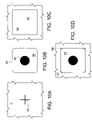
- FIG. 10A is an illustration of a section of a workpiece having an target image etched its surface.
- FIG. 10B is an illustration of a printed target image.
- FIG. 10C is an illustration of a section of a workpiece having a registration mark etched into its surface indicating where a target image is to be attached.
- FIG. 10D is an illustration of the section of workpiece of FIG. 10C with the target image of FIG. 10B attached to the workpiece.
- FIG. 11A is an illustration of the field of view of the image sensor.
- FIG. 11B is an illustration of an etched target image as seen by the image sensor.
- FIG. 11C is an illustration of a printed target image as seen by the image sensor sampled image display.
- FIG. 11D is an illustration of a captured image of a image target captured as a first step for determining X and Y pixel to unit of travel conversion factors.
- FIG. 11E is the an illustration of a captured image of the image target of FIG. 11D after the workhead has been repositioned one millimeter in the X and Y-axis directions as a second step for determining X and Y pixel to unit of travel conversion factors.
- FIG. 12 is an illustration of the laser machine tool of FIG. 1 with the work support moved to a second working position.
- FIG. 13 is an enlarged view of the laser machine tool working zone of FIG. 12 .
- FIG. 14A is an exemplar plot of image targets before and after the work support is indexed.
- FIG. 14B is a plot of the relative position of the image targets of FIG. 14A after having applied a coordinate rotation correction.
- FIG. 14C is a plot of the relative position of the image targets of FIG. 14B after having applied an X and Y coordinate shift correction.
- FIG. 15 is an illustration of a load station for a 10 foot by 60 foot workpiece with a workpiece having image targets affixed and ready for processing.
- FIG. 16 is an illustration of an image sensor mounted in a protective housing and adapted with a shield gas flow to keep the housing lens clean.
- FIG. 17 is an illustration of an image sensor mounted in a protective housing and adapted with a shutter to keep the housing lens clean.
- FIG. 1 is an illustration of a computer controlled laser machine tool 1 wherein a workpiece 2 is larger than a work zone 3 of the machine tool.
- the work zone 3 of exemplar machine tool 1 is nominally ten feet wide by 20 feet six inches long and the workpiece 2 is nominally ten feet wide by forty feet long.
- the work zone 3 is outlined and crossed by phantom lines 3 ′.
- the workpiece 2 is laying on a translatable work support 4 .
- the translatable work support 4 is also called a worktable or a pallet.
- the worktable 4 is residing on a load/unload station 5 and is driven in and out of the machine tool work zone by a friction drive apparatus 6 .
- a pair of wheels 7 and 7 ′ counteracts the driving forces of friction drive 6 such that the worktable 4 remains on its guide way.
- Support rails 8 and 8 ′ support the leading end of worktable 4 when it extends beyond the work zone 3 .
- Operator Station 9 is the man machine interface for the machine tool 1 .
- Electrical cabinet 10 houses a computer numerical control (CNC) 11 , servo drives 12 and other electrical and electronic control components for machine tool 1 .
- the CNC controls the movement and functioning of the machine tool in performing its machining functions. As an element of accomplishing that control, the CNC 11 maintains registration information of the workhead guidance system, as will be discussed further below.
- FIG. 2 is an illustration of the operator station 9 of machine tool 1 .
- the operator station 9 is comprised of a touch display screen 13 for displaying a program and or other information relative to the operation and control of machine tool 1 .
- a touch control screen 14 provides a machine operator various selectable control functions for machine tool 1 .
- a keyboard 15 provides an operator the capability to enter or edit machine control data.
- a plurality of switches 16 provide various laser control functions.
- Operator station 9 communicates with a personal computer 17 FIG. 3 .
- the personal computer (PC) 17 has a processor 18 and memory 19 for manipulating a control program 20 and digital data.
- PC 17 is mounted inside the operator's station 9 .
- the PC 17 has a hard drive 21 for storage of machine control programs and data.
- Optional floppy drive 22 and compact disk drive 23 provide capability to load or unload control programs and data for machine tool 1 .
- An optional modem 24 provides capability for remote factory service 25 of machine tool 1 via phone line 26 .
- An optional network card 27 provides capability for the machine tool 1 to be connected to a factory computer network 28 via cable 29 .
- the PC 17 communicates with the operator station 9 and the computer control 11 controlling machine tool 1 and participates in the control and operation of machine tool 1 .
- FIG. 4 is an enlarged view of the working area of the laser machine tool 1 of FIG. 1 .
- Machine tool 1 has a laser resonator 30 capable of emitting a laser beam 31 via an output coupler 32 to a mirror 33 where it is reflected along path 34 to mirror 35 .
- the laser beam is reflected from mirror 35 along path 36 to mirror 37 where it is directed through a collimator 38 .
- Exiting collimator 38 the beam is directed to mirror 39 and reflected along path 40 into beam path 41 parallel to the X-axis coordinate 42 of machine tool 1 .
- the beam impinges on mirror 43 then is reflected along path 44 parallel to the Y-axis coordinate 45 of machine tool 1 to mirror 46 .
- Mirror 46 is mounted on workhead 47 . Forward of mirror 46 is an image sensor apparatus 48 .
- the beam is reflected from mirror 46 along path 49 parallel to the Z-axis coordinate 50 through a focusing lens (not shown) mounted in a cartridge 51 and exits from nozzle 52 .
- the workhead 46 is adapted with a cutting head 53 .
- the cutting head 53 is driven parallel to the Z-axis 50 by a servomotor 54 that raises and lowers the cutting head 53 and nozzle 52 relative to the workpiece 2 .
- the X-axis 42 , Y-axis 45 and Z-axis 50 are mutually perpendicular.
- the workhead 47 is carried by linear bearings 55 on linear ways 56 and 56 ′ that are mounted to bridge assembly 57 . Best seen in FIG.
- the worktable 4 has a plurality of slats or blades 58 that support the workpiece 2 .
- the upper edge 59 of the slats 58 are cut in a saw-tooth fashion to minimize contact with the workpiece 2 .
- Worktable 4 is carried and guided on one side by a plurality of vee rollers 60 that ride on a inverted vee way 61 supported in part by support 8 .
- Worktable 4 is carried on the opposite side by a plurality of flat rollers 62 that ride on a flat way 63 supported in part by support 8 ′.
- the bridge 57 is carried by linear bearings 64 and 64 ′ riding on linear ways 65 and 65 ′ and is driven along the X-axis by linear servomotors 66 and 66 ′.
- linear servomotors 66 and 66 ′ When the worktable 4 is positioned in the work zone 3 its final position is located and locked in place by powered locators 67 and 67 ′.
- FIG. 5A is an enlarged illustration of the powered locator 67 and is shown in the released position.
- powered locator 67 is comprised of a driving cylinder 68 having a piston 69 and a piston rod 70 .
- Cylinder 68 is attached to a pin guide tube 71 .
- Piston rod 70 is attached to a locating pin 72 and is locked thereto by a nut 73 .
- Worktable 4 a fragment thereof is shown, is adapted with a socket 74 to receive the locating pin 72 .
- the piston 69 is shown in the retracted position such that the location pin 72 is retracted from the socket 74 and resides within the pin guide tube 71 .
- worktables are adapted with a plurality of sockets 74 and 74 ′ such that a pair of sockets is associated with each positioning of the worktable within the work zone 3 .
- FIG. 5B is an illustration of the powered locator 67 of FIG. 5A but is shown in the locked or locating position.
- the piston 69 is shown in the extended or locked position such that while a portion of the locating pin 72 remains within the guide tube 71 the locating pin 72 has entered the socket 74 such as to locate the final position of the worktable 4 and lock it in place.
- FIG. 7 is an illustration of the laser machine tool of FIG. 1 with the worktable 4 moved to a first working position such that the leading portion of the workpiece 2 resides within the work zone 3 .
- FIG. 8 is an enlarged illustration of the machine tool work zone of FIG. 7 .
- the X “0” 75 and Y “0” 76 coordinates are reference positions for the computer control system for positioning the workhead 47 relative to the workpiece 2 .
- Proximate the trailing edge of work zone 3 outlined by leading boundary line 77 and trailing boundary line 78 is an overlap zone 79 .
- the overlap zone 79 is such that its area is within the operating range of workhead nozzle 52 and of image sensor apparatus 48 .
- the overlap zone 79 is also such that when the worktable 4 is indexed to a second working position the leading boundary line 77 of overlap zone 79 will reside proximate the coordinate X “0” 75 of FIG. 8 .
- FIG. 9A is a partial side view illustration of the image sensor apparatus 48 mounted on the workhead 47 .
- the image sensor apparatus 48 in the illustrated embodiment is comprised of an image sensor 80 , enclosed in a housing 81 that is attached to a vertical member 82 of the cutting head 53 via brackets 83 and 84 and fasteners 85 and 86 . Other forms of mounting can also be used.
- the image sensor 80 is adapted with a lens spacer 87 , a focusing lens 88 and a Light Emitting Diode (LED) strobe light comprised of a plurality of LEDs 89 mounted about the focusing lens 88 .
- LED Light Emitting Diode
- the image sensor 80 is also called a vision system, an inspection camera or a SmartImage sensor such as a Model 530MR DVT inspection camera manufactured by DVT Corporation, Norcross, Ga.
- the housing 81 has a lens 90 , a lens retainer 91 and is adapted to accept a fitting 92 for being purged with a clean dry gas such as air or nitrogen.
- the lens 90 is preferably made of glass such that it can be periodically cleaned without scratching it.
- APG Vision, Allison Park, Pa. manufactures housings 81 for the SmartImage sensor 80 .
- FIG. 10A is an illustration of a section of a workpiece 2 that has a target image 93 etched into its surface for use with image sensor apparatus 48 .
- laser machine tools such as laser machine tool 1 can etch lines, numbers, letters or shapes into the surface of a workpiece.
- the laser machine tool 1 etches target images into the surface of the workpiece that are measured by the image sensor 80 before and after the worktable is indexed.
- Laser machine tool 1 can process several types of metal including carbon and construction grade steel, aluminum, brass, and stainless steel.
- the image sensor could not reliably measure the etched target image in certain types of metal, for example, carbon and construction grade steel. There was inadequate contrast between the etched target image and the surface of the metal for the inspection camera to make reliably accurate measurements.
- FIG. 10B is an illustration of a printed target 94 having a black, non-reflective target image 95 on a white background 96 .
- the printed target 94 is adhesive coated on its backside. Alternatively to having an adhesive coated backside it is thought that the printed target 94 can be printed on magnetic material and as such can be used many times.
- the white background 96 can be a gloss, semi-gloss or a non-reflective surface.
- the size, shape and color of the target image 95 is not very important as long as it fits entirely within approximately eighty percent or less of the camera field of view, has a non-reflective surface finish and contrasts well with the background 96 .
- the image sensor 80 has integrated measurement tools or functions that can determine the center of shapes, called blobs.
- a target image is preferably a symmetrical shape. Background 96 size, shape and color is also not important as long as it contrasts well with the target image 95 .
- a workhead nozzle capacitive height control system can accurately sense a workpiece through the printed target 94 .
- FIG. 10C is an illustration of a section of a workpiece 97 having a registration mark or shape 98 etched into its surface indicating where a printed target 94 is to be attached.
- FIG. 10D is an illustration of the section of workpiece 97 of FIG. 10C with the printed target 94 of FIG. 7B attached relative to the registration mark 98 .
- FIG. 11A is an illustration of a Charged Coupled Device (CCD) 99 of the image sensor 80 and its corresponding Field Of View (FOV) size as adapted for the present invention.
- the FOV is the area that can be seen by the image sensor.
- the FOV size is dependent on the CCD size and the working distance 100 , FIG. 9A , the distance from the camera lens to the part to be viewed.
- FIG. 11A represents the heart of the image sensor 80 .
- the CCD 99 is divided into smaller elements called pixels.
- Each pixel 101 shown in enlarged view 102 , measures light intensity and translates it into an electrical voltage.
- the number of pixels that exist horizontally and vertically on a CCD and the FOV size defines the resolution of an image.
- the inspection camera chosen for an initial embodiment has a CCD size of 4.8 mm 103 ⁇ 3.6 mm 104 containing 307,200 pixels, 640 pixels per row 105 and 480 rows 106 .
- each pixel 101 is 7.4 micrometers square.
- the CCD size and the 16 inch working distance chosen for this embodiment produces a FOV measuring approximately 2 inches 107 ⁇ 1.5 inches 108 .
- the image sensor 80 is mounted on exemplar machine tool 1 such that the 2 inch FOV dimension 107 is parallel to the X-axis of laser machine tool 1 and the 1.5 inch FOV dimension 108 is parallel to the Y-axis.
- the center of the CCD is 320 pixels 109 and 240 pixels 110 from the upper left corner of the FOV.
- FIG. 11B is an illustration of an etched target image 111 as seen by the image sensor 80 .
- Imaginary horizontal 112 and vertical 113 dotted lines are shown through the centerline of the FOV 114 for reference.
- the cutting head 53 is adapted with a control apparatus 115 to automatically control the nozzle to workpiece stand off distance 116 .
- the control apparatus 115 provides feedback for the Z-axis servomotor 54 , FIG. 6 , to control the standoff distance 116 , the distance between the bottom of the nozzle 52 and the upper surface 117 of a workpiece 118 .
- the control apparatus 115 is a capacitive sensor apparatus but other types of stand off control apparatuses are suitable.
- the image sensor 80 requires some initial setup before it can be used. Such setup only has to be done one time but can be checked periodically or optionally redone.
- a standoff distance 116 is selected as a standard value for use with the image sensor.
- the nozzle 52 is positioned over a target 119 and the Z-axis is lowered under automatic control until the nozzle 52 reaches the commanded standoff distance 116 .
- the Z-axis position is then frozen such that the capacitive sensor ignores any change in standoff height until unfrozen.
- the workhead 47 is then moved an offset distance 120 such that the image sensor lens 88 is centered over the target 119 , FIG. 9B .
- the lens 88 focusing mechanism 121 is then turned until the target image 122 FIG. 11C is sharp in a sampled image display 123 and the inspection camera exposure time is set to capture a good image.
- the LED strobe lights 89 FIG. 9B are turned on to illuminate the target 119 as depicted by dashed lines 124 .
- a setup calibration program is run to determine X and Y pixels to unit of travel conversion factors, i.e. pixels per millimeter travel.
- An image 125 is captured of a target 126 FIG. 11D .
- Imaginary horizontal 127 and vertical 128 dotted lines have been added to image 125 to reference the center of the FOV.
- Imaginary short solid horizontal 129 and vertical 130 lines have been added to the target image 126 to reference the center of the target.
- the captured target image 126 is slightly left and above the FOV center.
- the image 126 is measured by the inspection camera 80 to determine the location of the target's horizontal dimension X 1 131 and vertical dimension Y 1 132 , in pixels, relative to the FOV center.
- the image sensor's integrated measurement tools can determine the target's position within 0.1 pixel.
- the workhead 47 is repositioned one millimeter in the X-axis 42 and Y-axis 45 coordinates, reference FIG. 4 , and another image 133 FIG. 11E is captured.
- the image 133 is measured by the inspection camera 80 to determine the location of the target 126 ′ horizontal dimension X 2 134 and vertical dimension Y 2 135 , in pixels, relative to the FOV center.
- the absolute value of X 1 -X 2 equals an X-axis pixels per millimeter travel constant.
- the absolute value of Y 1 -Y 2 equals a Y-axis pixels per millimeter travel constant. Pixels per millimeter travel constants are stored in computer memory. Pixels per millimeter of travel constants are divided by 25.4 to determine pixels per inch travel constants.
- workpiece 2 in the first working position is shown having interrupted cuts 136 , 137 , 138 , 139 , 140 , and 141 all terminating within the overlap zone 79 .
- Magnified views 142 and 143 show target images 144 and 145 etched into the surface of workpiece 2 within the overlap zone 79 .
- the target images 144 and 145 are etched into the surface of the workpiece 2 by the laser 30 and the workhead 47 spaced as far apart as practical in the Y coordinate 45 FIG. 4 . Referencing FIG.
- FIG. 9A the nozzle 52 of the workhead 47 is positioned over the image target 144 and the Z-axis is lowered until the nozzle 52 reaches the commanded standoff distance 116 .
- Auxiliary side jet apparatus 146 FIG. 9A is a gaseous blast source typically used for piercing carbon steel. The auxiliary side jet apparatus 146 is cycled to blow any residue from the cutting process off of image target 144 . The Z-axis position is frozen such that the capacitive sensor 115 ignores any change in standoff height.
- the workhead 47 is moved the offset distance 120 such that the image sensor lens 88 is approximately centered over the target 144 , reference FIG. 9B .
- the inspection camera 80 captures an image of the target 144 .
- the commercially available inspection camera has integrated measurement tools which are used to determine the position of target 144 relative to the center of the field of view.
- the position of target 144 is stored in computer memory.
- the Z-axis position is unfrozen and the nozzle 52 of the workhead 47 is positioned over image target 145 .
- the position of image target 145 is measured and stored in computer memory.
- the X and Y distance of image target 145 and rotation angle relative to target 144 are calculated and stored in computer memory.
- the workhead 47 is then moved to a target location for a post index inspection proximate X “0” and the work support 4 is indexed to a second work position.
- FIG. 12 is an illustration of the laser machine tool of FIG. 1 with the worktable 4 moved to a second working position such that the leading portion of the worktable 4 and workpiece 2 is supported by support rails 8 and 8 ′ and the trailing portion of the workpiece 2 and worktable 4 resides within the work zone 3 .
- FIG. 13 is an enlarged illustration of the working zone of the machine tool of FIG. 12 .
- the bridge assembly 57 is shown broken away so that the overlap work zone 79 can be clearly seen.
- the leading overlap work zone boundary line 77 FIG. 13
- the former X “0” position 75 is reset, equal the length of the index, to X 6096 millimeters 75 ′ in the exemplar machine tool shown.
- the image sensor determines the position of image targets 144 and 145 .
- the target position information is stored in computer memory as separate, post work support index positions.
- FIGS. 14A through 14C illustrate the method of checking and maintaining the registration of a workpiece when the work support is indexed to another working position.
- FIG. 14A is an exemplar plot of target images before and after the work support 4 is indexed. Though the present invention functions by software program and mathematical analysis, graphical plots better illustrate the process, and will enable one skilled in the art to program appropriate steps and calculations into a computer of the computer controlled machine tool to accomplish what will now be demonstrated graphically.
- the position of target image 148 is plotted with respect to the position of target image 147 .
- X 1 149 is the X-axis distance between target images.
- Y 1 150 is the Y-axis distance between target images.
- a 1 151 is the rotational angle between target images.
- the targets, being physically positioned on the workpiece, have a given separation and orientation, and imaging of those targets by the steps just described stores the relative position and orientation in computer memory.
- 147 ′ is the position of target image 147 after the work support was indexed.
- 148 ′ is the position of target image 148 after the work support was indexed.
- X 2 152 is the measured X-axis distance between target images 147 ′ and 148 ′ after the work support was indexed.
- Y 2 153 is the measured Y-axis distance between target images 147 ′ and 148 ′ after the work support was indexed.
- a 2 154 is the rotational angle between target images 147 ′ and 148 ′ after the work support was indexed.
- a processor preferably the processor in the imaging system, but also potentially the CNC processor can determine errors introduced by indexing.
- XC 155 is the X distance correction that must be applied to make the position of the post index target image 147 ′ equal to the pre index position 147 .
- YC 156 is the Y distance correction that must be applied to make the position of the post index target image 147 ′ equal to the pre index position 147 .
- Computer controls such as CNC 11 used to control laser machine tools have capability to adjust the reference coordinate system by rotating and/or shifting the coordinate system to simplify programming complex shapes and patterns.
- the present invention utilizes such capabilities to maintain registration of the controlling coordinate system relative to the workpiece though the workpiece position may shift when the work support is indexed.
- the CNC 11 in FIG. 1 is shown with an input derived from the image sensor 48
- the image sensor 48 shown in FIG. 9B is shown with an output to direct position information to the CNC.
- the commercially available image sensor produces error information as described herein, and the error information is utilized in the known coordinate adjustment systems in the CNC for adjusting the coordinate system to accommodate for positional errors introduced in indexing.
- FIG. 14B is a plot of the relative position of the target images of FIG. 14A after having applied a coordinate rotation correction equal to angle A 2 minus angle A 1 .
- Angle A 2 154 is equal to angle A 1 151 and the position of target image plots 147 ′ and 148 ′ are parallel to the position of target image plots 147 and 148 .
- FIG. 14C is a plot of the relative positions of the target images of FIG. 14B after having applied X and Y coordinate shift corrections equal to XC 155 and YC 156 .
- the position of target image 147 ′ plots the same as target image 147
- the position of target image 148 ′ plots the same as target image 148 indicating registration of the co-ordinate system relative to the work head has been restored.
- the position of target images is again determined and checked in the manner previously described and compared with pre-index target image positions and set error limits. If the target image positions are within set error limits the laser machine continues processing the workpiece restarting and finishing the interrupted cuts and performing other operations per part program. If the target image positions are not within set error limits another attempt to correct registration is made following the previously described process. The number of attempts to achieve registration is settable. If registration is not achieved within the set number of attempts an error message is displayed on the operator station and the machine tool stops operation waiting for operator attention.
- FIG. 15 is an illustration of an optional load station 157 for laser machine tool 1 having a capacity for a 10 foot by 60 foot workpiece 158 .
- the 10 foot by 60 foot workpiece 158 must indexed a plurality of times to be processed by laser machine tool 1 .
- a plurality of overlapping work zones 159 and 160 are shown.
- Magnified views 161 and 162 show image targets 163 and 164 are affixed to the surface of workpiece 158 within overlap work zone 159 .
- Magnified views 165 and 166 show image targets 167 and 168 are affixed to the surface of workpiece 158 within overlap work zone 160 .
- the workpiece 158 is ready for processing by computer controlled laser machine tool 1 .
- the targets 163 , 164 , 167 , and 168 are affixed to the workpiece 158 relative to registration marks etched into the surface of the workpiece by laser machine tool 1 . In etching such registration marks before processing the workpiece, it is not necessary to maintain the registration of the co-ordinate system between work support indexes. Target image and Field Of View size is selected such that any error introduced in indexing the work support for etching registration marks falls well within the field of view of the image sensor 48 thus can be compensated for later.
- the targets 163 , 164 , 167 , and 168 are affixed to the workpiece 158 by measuring their position from a leading corner of the workpiece such as 169 .
- FIG. 16 is an illustration of an image sensor 170 mounted in a protective housing 171 and adapted to provide a shield gas flow 172 via nozzle 173 mounted proximate to the lens to keep the housing lens 174 clean.
- FIG. 17 is an illustration of an image sensor 175 mounted in a protective housing 176 and provided with a shutter 177 to keep the housing lens 178 clean.
- the shutter 177 is driven by a rotary solenoid 179 .
- the shutter can be driven by a pneumatic actuator. The shutter is opened just prior to and during operation of the image sensor 175 , otherwise it remains closed over lens 178 protecting it from dust.
Abstract
Description
Claims (39)
Priority Applications (1)
| Application Number | Priority Date | Filing Date | Title |
|---|---|---|---|
| US10/658,162 US7005606B2 (en) | 2003-09-09 | 2003-09-09 | Laser machine tool with image sensor for registration of workhead guidance system |
Applications Claiming Priority (1)
| Application Number | Priority Date | Filing Date | Title |
|---|---|---|---|
| US10/658,162 US7005606B2 (en) | 2003-09-09 | 2003-09-09 | Laser machine tool with image sensor for registration of workhead guidance system |
Publications (2)
| Publication Number | Publication Date |
|---|---|
| US20050051523A1 US20050051523A1 (en) | 2005-03-10 |
| US7005606B2 true US7005606B2 (en) | 2006-02-28 |
Family
ID=34226732
Family Applications (1)
| Application Number | Title | Priority Date | Filing Date |
|---|---|---|---|
| US10/658,162 Expired - Fee Related US7005606B2 (en) | 2003-09-09 | 2003-09-09 | Laser machine tool with image sensor for registration of workhead guidance system |
Country Status (1)
| Country | Link |
|---|---|
| US (1) | US7005606B2 (en) |
Cited By (23)
| Publication number | Priority date | Publication date | Assignee | Title |
|---|---|---|---|---|
| US20090065488A1 (en) * | 2007-08-31 | 2009-03-12 | Zhaoli Hu | Laser machining calibration method |
| US8175742B1 (en) * | 2003-04-08 | 2012-05-08 | Arvin Joseph L | Apparatus and method for machining workpieces |
| CN105127601A (en) * | 2015-08-31 | 2015-12-09 | 宝山钢铁股份有限公司 | Laser cutting method and device for symmetrical parts |
| US9289852B2 (en) | 2011-01-27 | 2016-03-22 | Bystronic Laser Ag | Laser processing machine, laser cutting machine, and method for adjusting a focused laser beam |
| US9296067B2 (en) | 2011-01-27 | 2016-03-29 | Bystronic Laser Ag | Laser processing machine, in particular laser cutting machine, and method for centering a laser beam, in particular a focused laser beam |
| US9498231B2 (en) | 2011-06-27 | 2016-11-22 | Board Of Regents Of The University Of Nebraska | On-board tool tracking system and methods of computer assisted surgery |
| USD786323S1 (en) * | 2014-06-06 | 2017-05-09 | Hybrid Manufacturing Technologies Llc | Replaceable processing head for computer numerical control (CNC) machines |
| CN107438800A (en) * | 2015-02-12 | 2017-12-05 | 格罗弗治公司 | The mobile material in laser processing procedure |
| US9839975B2 (en) | 2013-12-12 | 2017-12-12 | Bystronic Laser Ag | Method for configuring a laser machining machine |
| US9937590B2 (en) * | 2010-07-22 | 2018-04-10 | Bystronic Laser Ag | Laser processing machine |
| US10105149B2 (en) | 2013-03-15 | 2018-10-23 | Board Of Regents Of The University Of Nebraska | On-board tool tracking system and methods of computer assisted surgery |
| US10219811B2 (en) | 2011-06-27 | 2019-03-05 | Board Of Regents Of The University Of Nebraska | On-board tool tracking system and methods of computer assisted surgery |
| US10551824B2 (en) | 2016-11-25 | 2020-02-04 | Glowforge Inc. | Controlled deceleration of moveable components in a computer numerically controlled machine |
| US10802465B2 (en) | 2016-11-25 | 2020-10-13 | Glowforge Inc. | Multi-user computer-numerically-controlled machine |
| US11116574B2 (en) | 2006-06-16 | 2021-09-14 | Board Of Regents Of The University Of Nebraska | Method and apparatus for computer aided surgery |
| US11137738B2 (en) | 2016-11-25 | 2021-10-05 | Glowforge Inc. | Calibration of a computer-numerically-controlled machine |
| US20210323096A1 (en) * | 2018-10-16 | 2021-10-21 | Schuler Pressen Gmbh | Method and device for laser cutting a sheet metal blank from a continuously conveyed sheet metal strip |
| US11249456B2 (en) | 2016-11-25 | 2022-02-15 | Glowforge Inc. | Fabrication with image tracing |
| US11305379B2 (en) | 2016-11-25 | 2022-04-19 | Glowforge Inc. | Preset optical components in a computer numerically controlled machine |
| US11433477B2 (en) | 2016-11-25 | 2022-09-06 | Glowforge Inc. | Housing for computer-numerically-controlled machine |
| US11698622B2 (en) | 2021-03-09 | 2023-07-11 | Glowforge Inc. | Previews for computer numerically controlled fabrication |
| US11740608B2 (en) | 2020-12-24 | 2023-08-29 | Glowforge, Inc | Computer numerically controlled fabrication using projected information |
| US11911117B2 (en) | 2011-06-27 | 2024-02-27 | Board Of Regents Of The University Of Nebraska | On-board tool tracking system and methods of computer assisted surgery |
Families Citing this family (13)
| Publication number | Priority date | Publication date | Assignee | Title |
|---|---|---|---|---|
| JP2006041117A (en) * | 2004-07-26 | 2006-02-09 | Matsushita Electric Ind Co Ltd | Method of manufacturing solid-state imaging device |
| US7709765B2 (en) * | 2005-12-28 | 2010-05-04 | Hypertherm, Inc. | Networking architecture for thermal processing system |
| EP2062674B1 (en) * | 2007-11-20 | 2016-11-02 | TRUMPF Werkzeugmaschinen GmbH + Co. KG | Method for preparing and carrying out a laser welding process |
| US20100098399A1 (en) * | 2008-10-17 | 2010-04-22 | Kurt Breish | High intensity, strobed led micro-strip for microfilm imaging system and methods |
| US8481982B2 (en) * | 2009-08-17 | 2013-07-09 | Scot L Johnson | Energy emitting treatment device |
| CH700111B1 (en) * | 2009-09-25 | 2010-06-30 | Agie Sa | Machine for making three-dimensional workpiece using focused beam of laser light causing local evaporation of particle of matter on workpiece surface, comprises laser machining head, laser source, galvanometer scanner, and optical fiber |
| US10509390B2 (en) * | 2015-02-12 | 2019-12-17 | Glowforge Inc. | Safety and reliability guarantees for laser fabrication |
| WO2018098395A1 (en) | 2016-11-25 | 2018-05-31 | Glowforge Inc. | Improved engraving in a computer numerically controlled machine |
| CN114274260A (en) * | 2017-04-05 | 2022-04-05 | 速特系统技术股份公司 | Cutting machine and machine-readable carrier |
| US10695227B2 (en) * | 2017-06-07 | 2020-06-30 | Kci Licensing, Inc. | Methods for manufacturing and assembling dual material tissue interface for negative-pressure therapy |
| JP2023538823A (en) | 2020-07-31 | 2023-09-12 | アークバイト、インク. | Non-contact drilling system and method |
| CN112296508B (en) * | 2020-11-02 | 2021-09-10 | 吉林大学 | Laser automatic processing platform |
| US11591909B2 (en) | 2021-01-12 | 2023-02-28 | EarthGrid PBC | Tunnel boring system |
Citations (5)
| Publication number | Priority date | Publication date | Assignee | Title |
|---|---|---|---|---|
| US5132510A (en) | 1990-09-04 | 1992-07-21 | Trumpf, Inc. | Laser machine assembly for flow of workpieces therethrough and method of using same |
| US5304773A (en) * | 1992-02-19 | 1994-04-19 | Trumpf Inc. | Laser work station with optical sensor for calibration of guidance system |
| US5751436A (en) * | 1996-12-23 | 1998-05-12 | Rocky Mountain Instrument Company | Method and apparatus for cylindrical coordinate laser engraving |
| US6044308A (en) * | 1997-06-13 | 2000-03-28 | Huissoon; Jan Paul | Method and device for robot tool frame calibration |
| US6204473B1 (en) * | 1999-04-30 | 2001-03-20 | W.A. Whitney Co. | Laser-equipped machine tool cutting head with pressurized counterbalance |
-
2003
- 2003-09-09 US US10/658,162 patent/US7005606B2/en not_active Expired - Fee Related
Patent Citations (5)
| Publication number | Priority date | Publication date | Assignee | Title |
|---|---|---|---|---|
| US5132510A (en) | 1990-09-04 | 1992-07-21 | Trumpf, Inc. | Laser machine assembly for flow of workpieces therethrough and method of using same |
| US5304773A (en) * | 1992-02-19 | 1994-04-19 | Trumpf Inc. | Laser work station with optical sensor for calibration of guidance system |
| US5751436A (en) * | 1996-12-23 | 1998-05-12 | Rocky Mountain Instrument Company | Method and apparatus for cylindrical coordinate laser engraving |
| US6044308A (en) * | 1997-06-13 | 2000-03-28 | Huissoon; Jan Paul | Method and device for robot tool frame calibration |
| US6204473B1 (en) * | 1999-04-30 | 2001-03-20 | W.A. Whitney Co. | Laser-equipped machine tool cutting head with pressurized counterbalance |
Cited By (37)
| Publication number | Priority date | Publication date | Assignee | Title |
|---|---|---|---|---|
| US8175742B1 (en) * | 2003-04-08 | 2012-05-08 | Arvin Joseph L | Apparatus and method for machining workpieces |
| US11116574B2 (en) | 2006-06-16 | 2021-09-14 | Board Of Regents Of The University Of Nebraska | Method and apparatus for computer aided surgery |
| US11857265B2 (en) | 2006-06-16 | 2024-01-02 | Board Of Regents Of The University Of Nebraska | Method and apparatus for computer aided surgery |
| US9302345B2 (en) * | 2007-08-31 | 2016-04-05 | Caterpillar Inc. | Laser machining calibration method |
| US20090065488A1 (en) * | 2007-08-31 | 2009-03-12 | Zhaoli Hu | Laser machining calibration method |
| US20180161938A1 (en) * | 2010-07-22 | 2018-06-14 | Bystronic Laser Ag | Laser processing machine |
| US10086475B2 (en) * | 2010-07-22 | 2018-10-02 | Bystronic Laser Ag | Laser processing machine |
| US9937590B2 (en) * | 2010-07-22 | 2018-04-10 | Bystronic Laser Ag | Laser processing machine |
| US9289852B2 (en) | 2011-01-27 | 2016-03-22 | Bystronic Laser Ag | Laser processing machine, laser cutting machine, and method for adjusting a focused laser beam |
| US9296067B2 (en) | 2011-01-27 | 2016-03-29 | Bystronic Laser Ag | Laser processing machine, in particular laser cutting machine, and method for centering a laser beam, in particular a focused laser beam |
| US9498231B2 (en) | 2011-06-27 | 2016-11-22 | Board Of Regents Of The University Of Nebraska | On-board tool tracking system and methods of computer assisted surgery |
| US10219811B2 (en) | 2011-06-27 | 2019-03-05 | Board Of Regents Of The University Of Nebraska | On-board tool tracking system and methods of computer assisted surgery |
| US11911117B2 (en) | 2011-06-27 | 2024-02-27 | Board Of Regents Of The University Of Nebraska | On-board tool tracking system and methods of computer assisted surgery |
| US10080617B2 (en) | 2011-06-27 | 2018-09-25 | Board Of Regents Of The University Of Nebraska | On-board tool tracking system and methods of computer assisted surgery |
| US10105149B2 (en) | 2013-03-15 | 2018-10-23 | Board Of Regents Of The University Of Nebraska | On-board tool tracking system and methods of computer assisted surgery |
| US9839975B2 (en) | 2013-12-12 | 2017-12-12 | Bystronic Laser Ag | Method for configuring a laser machining machine |
| USD820893S1 (en) * | 2014-06-06 | 2018-06-19 | Hybrid Manufacturing Technologies Llc | Replaceable processing head for computer numerical control (CNC) machines |
| USD837845S1 (en) * | 2014-06-06 | 2019-01-08 | Hybrid Manufacturing Technologies Llc | Replaceable processing head for computer numerical control (CNC) machines |
| USD786323S1 (en) * | 2014-06-06 | 2017-05-09 | Hybrid Manufacturing Technologies Llc | Replaceable processing head for computer numerical control (CNC) machines |
| CN107438800A (en) * | 2015-02-12 | 2017-12-05 | 格罗弗治公司 | The mobile material in laser processing procedure |
| CN105127601B (en) * | 2015-08-31 | 2018-03-09 | 宝山钢铁股份有限公司 | A kind of laser cutting method of symmetrical member |
| CN105127601A (en) * | 2015-08-31 | 2015-12-09 | 宝山钢铁股份有限公司 | Laser cutting method and device for symmetrical parts |
| US11305379B2 (en) | 2016-11-25 | 2022-04-19 | Glowforge Inc. | Preset optical components in a computer numerically controlled machine |
| US11860606B2 (en) | 2016-11-25 | 2024-01-02 | Glowforge, Inc. | Fabrication with image tracing |
| US11249456B2 (en) | 2016-11-25 | 2022-02-15 | Glowforge Inc. | Fabrication with image tracing |
| US11281189B2 (en) | 2016-11-25 | 2022-03-22 | Glowforge Inc. | Controlled deceleration of moveable components in a computer numerically controlled machine |
| US11137738B2 (en) | 2016-11-25 | 2021-10-05 | Glowforge Inc. | Calibration of a computer-numerically-controlled machine |
| US11433477B2 (en) | 2016-11-25 | 2022-09-06 | Glowforge Inc. | Housing for computer-numerically-controlled machine |
| US11460828B2 (en) | 2016-11-25 | 2022-10-04 | Glowforge Inc. | Multi-user computer-numerically-controlled machine |
| US10551824B2 (en) | 2016-11-25 | 2020-02-04 | Glowforge Inc. | Controlled deceleration of moveable components in a computer numerically controlled machine |
| US10802465B2 (en) | 2016-11-25 | 2020-10-13 | Glowforge Inc. | Multi-user computer-numerically-controlled machine |
| US11835936B2 (en) | 2016-11-25 | 2023-12-05 | Glowforge, Inc. | Multi-user computer-numerically-controlled machine |
| US11860601B2 (en) | 2016-11-25 | 2024-01-02 | Glowforge Inc. | Calibration of a computer-numerically-controlled machine |
| US20210323096A1 (en) * | 2018-10-16 | 2021-10-21 | Schuler Pressen Gmbh | Method and device for laser cutting a sheet metal blank from a continuously conveyed sheet metal strip |
| US11911851B2 (en) * | 2018-10-16 | 2024-02-27 | Schuler Pressen Gmbh | Method and device for laser cutting a sheet metal blank from a continuously conveyed sheet metal strip |
| US11740608B2 (en) | 2020-12-24 | 2023-08-29 | Glowforge, Inc | Computer numerically controlled fabrication using projected information |
| US11698622B2 (en) | 2021-03-09 | 2023-07-11 | Glowforge Inc. | Previews for computer numerically controlled fabrication |
Also Published As
| Publication number | Publication date |
|---|---|
| US20050051523A1 (en) | 2005-03-10 |
Similar Documents
| Publication | Publication Date | Title |
|---|---|---|
| US7005606B2 (en) | Laser machine tool with image sensor for registration of workhead guidance system | |
| TWI290363B (en) | Method and system for marking a workpiece such as a semiconductor wafer and laser marker for use therein | |
| US20090145888A1 (en) | Preparing and performing of a laser welding process | |
| JP5679560B2 (en) | Dimension measuring apparatus, dimension measuring method and program for dimension measuring apparatus | |
| JP2006136923A (en) | Laser beam machine and laser beam machining method | |
| EP1707293A1 (en) | Method and device for measuring and adjusting the electrode for taper machining on an electrical discharge machine | |
| JP6663807B2 (en) | Image measuring device | |
| JP3678915B2 (en) | Non-contact 3D measuring device | |
| US6301007B1 (en) | Machine tool locator | |
| US20110085177A1 (en) | Offset amount calibrating method and surface profile measuring machine | |
| GB2536167A (en) | Surface shape measuring device and machine tool provided with same, and surface shape measuring method | |
| CN112839765A (en) | Method for determining characteristic variables of a machining process and machining device | |
| CN114160961A (en) | System and method for calibrating laser processing parameters | |
| KR100925647B1 (en) | Sensing device and its method for compensating tool position processing oil-groove inside of engine cylinder | |
| JP2016040531A (en) | Working tool measuring method and measuring device | |
| JP3215193B2 (en) | Method and apparatus for measuring blade shape of rotary tool | |
| JP4668023B2 (en) | Paste coating apparatus and paste coating method | |
| JP4571256B2 (en) | Shape accuracy measuring device by sequential two-point method and laser displacement meter interval measuring method for shape accuracy measurement by sequential two-point method | |
| JP3162580B2 (en) | Dicing equipment | |
| JP2000074644A (en) | Measuring apparatus of rod type cutting tool and measuring method of drill which uses the measuring apparatus | |
| CN114096369A (en) | Control device, laser processing system with control device, and laser processing method | |
| JP2007305696A (en) | Accuracy measuring method of positioning apparatus | |
| JP3614680B2 (en) | Laser processing method and apparatus | |
| JP5389995B1 (en) | Measuring system and machine tool equipped with the measuring system | |
| JPH0763923B2 (en) | Origin correction method in NC processing device |
Legal Events
| Date | Code | Title | Description |
|---|---|---|---|
| AS | Assignment |
Owner name: W.A. WHITNEY CO., ILLINOIS Free format text: ASSIGNMENT OF ASSIGNORS INTEREST;ASSIGNORS:LEGGE, JOHN C.;BERRY, JIMMY D.;FARRIS, ROBERT J.;REEL/FRAME:014772/0794 Effective date: 20030909 |
|
| AS | Assignment |
Owner name: PNC BANK, NATIONAL ASSOCIATION, PENNSYLVANIA Free format text: AMENDED AND RESTATED PATENT, TRADEMARK AND COPYRIGHT SECURITY AGREEMENT;ASSIGNORS:W.A. WHITNEY CO.;MEGA FABRICATION, INC.;MEGA MANUFACTURING, INC.;AND OTHERS;REEL/FRAME:022659/0235 Effective date: 20090506 |
|
| REMI | Maintenance fee reminder mailed | ||
| LAPS | Lapse for failure to pay maintenance fees | ||
| STCH | Information on status: patent discontinuation |
Free format text: PATENT EXPIRED DUE TO NONPAYMENT OF MAINTENANCE FEES UNDER 37 CFR 1.362 |
|
| FP | Lapsed due to failure to pay maintenance fee |
Effective date: 20100228 |
|
| AS | Assignment |
Owner name: WHITNEY HOLDINGS, INC., KANSAS Free format text: RELEASE BY SECURED PARTY;ASSIGNOR:PNC BANK, NATIONAL ASSOCIATION;REEL/FRAME:062694/0734 Effective date: 20230213 Owner name: MEGA MANUFACTURING, INC., KANSAS Free format text: RELEASE BY SECURED PARTY;ASSIGNOR:PNC BANK, NATIONAL ASSOCIATION;REEL/FRAME:062694/0734 Effective date: 20230213 Owner name: MEGA FABRICATION, INC., KANSAS Free format text: RELEASE BY SECURED PARTY;ASSIGNOR:PNC BANK, NATIONAL ASSOCIATION;REEL/FRAME:062694/0734 Effective date: 20230213 Owner name: W.A. WHITNEY CO., KANSAS Free format text: RELEASE BY SECURED PARTY;ASSIGNOR:PNC BANK, NATIONAL ASSOCIATION;REEL/FRAME:062694/0734 Effective date: 20230213 |