US6466466B1 - Stable artificial neutral point in a three phase network of single phase rectifiers - Google Patents
Stable artificial neutral point in a three phase network of single phase rectifiers Download PDFInfo
- Publication number
- US6466466B1 US6466466B1 US09/674,573 US67457301A US6466466B1 US 6466466 B1 US6466466 B1 US 6466466B1 US 67457301 A US67457301 A US 67457301A US 6466466 B1 US6466466 B1 US 6466466B1
- Authority
- US
- United States
- Prior art keywords
- phase
- neutral point
- rectifiers
- winding
- transformer
- Prior art date
- Legal status (The legal status is an assumption and is not a legal conclusion. Google has not performed a legal analysis and makes no representation as to the accuracy of the status listed.)
- Expired - Lifetime
Links
Images


Classifications
-
- H—ELECTRICITY
- H02—GENERATION; CONVERSION OR DISTRIBUTION OF ELECTRIC POWER
- H02M—APPARATUS FOR CONVERSION BETWEEN AC AND AC, BETWEEN AC AND DC, OR BETWEEN DC AND DC, AND FOR USE WITH MAINS OR SIMILAR POWER SUPPLY SYSTEMS; CONVERSION OF DC OR AC INPUT POWER INTO SURGE OUTPUT POWER; CONTROL OR REGULATION THEREOF
- H02M7/00—Conversion of ac power input into dc power output; Conversion of dc power input into ac power output
- H02M7/02—Conversion of ac power input into dc power output without possibility of reversal
- H02M7/04—Conversion of ac power input into dc power output without possibility of reversal by static converters
- H02M7/12—Conversion of ac power input into dc power output without possibility of reversal by static converters using discharge tubes with control electrode or semiconductor devices with control electrode
- H02M7/21—Conversion of ac power input into dc power output without possibility of reversal by static converters using discharge tubes with control electrode or semiconductor devices with control electrode using devices of a triode or transistor type requiring continuous application of a control signal
- H02M7/217—Conversion of ac power input into dc power output without possibility of reversal by static converters using discharge tubes with control electrode or semiconductor devices with control electrode using devices of a triode or transistor type requiring continuous application of a control signal using semiconductor devices only
-
- H—ELECTRICITY
- H02—GENERATION; CONVERSION OR DISTRIBUTION OF ELECTRIC POWER
- H02J—CIRCUIT ARRANGEMENTS OR SYSTEMS FOR SUPPLYING OR DISTRIBUTING ELECTRIC POWER; SYSTEMS FOR STORING ELECTRIC ENERGY
- H02J3/00—Circuit arrangements for ac mains or ac distribution networks
- H02J3/26—Arrangements for eliminating or reducing asymmetry in polyphase networks
-
- Y—GENERAL TAGGING OF NEW TECHNOLOGICAL DEVELOPMENTS; GENERAL TAGGING OF CROSS-SECTIONAL TECHNOLOGIES SPANNING OVER SEVERAL SECTIONS OF THE IPC; TECHNICAL SUBJECTS COVERED BY FORMER USPC CROSS-REFERENCE ART COLLECTIONS [XRACs] AND DIGESTS
- Y02—TECHNOLOGIES OR APPLICATIONS FOR MITIGATION OR ADAPTATION AGAINST CLIMATE CHANGE
- Y02E—REDUCTION OF GREENHOUSE GAS [GHG] EMISSIONS, RELATED TO ENERGY GENERATION, TRANSMISSION OR DISTRIBUTION
- Y02E40/00—Technologies for an efficient electrical power generation, transmission or distribution
- Y02E40/50—Arrangements for eliminating or reducing asymmetry in polyphase networks
Definitions
- the present invention relates to a multiple-phase rectifying apparatus for use in an electric supply system comprising two or more phases, said apparatus comprising a single phase rectifier having a first and a second primary terminal, for each phase, each rectifier connected by its first primary terminal to the respective phase, the second primary terminals of said rectifiers being interconnected.
- a rectifier for a three phase network may be designed using three single phase rectifiers connected in a star configuration. For example, for a 3 ⁇ 400V network, three 230V rectifiers may be used.
- the neutral point created by the three rectifiers in a star configuration may be unstable. Asymmetric effects between the phases may occur both in the stationary and the transient state. Oscillations may be induced in rectifiers that are normally stable, when supplied from a low impedance network. This is because each rectifier “sees” the mains through two other rectifiers making it a high impedance network.
- a multiple-phase rectifying apparatus as initially defined, characterized in that it comprises means connectable in parallel with said single-phase rectifiers for creating a neutral point in the electric supply system.
- the creation of a neutral point independently of the neutral point of the supply network, especially in cases where the neutral potential is not located in the middle of the phase vector system is enabled.
- the means for creating a neutral point is not connected to the neutral conductor of the electric system.
- the means for creating a neutral point preferably includes magnetic components of such a kind that the vector sum of the phase voltages is zero.
- said means for creating a neutral point is arranged to short-circuit the zero sequence component of the phase voltages without affecting the positive and negative sequence components.
- the means for creating a neutral point comprises one transformer for each phase, the primary winding of each transformer connected to the respective phase in a star configuration, the secondary windings serially connected and the interconnection point of the primary windings forming said neutral point.
- the means for creating a neutral point comprises one winding for each phase, each winding wound on one leg of a common three-legged core, one end of each winding connected to the respective phase and the other end of each winding being interconnected, the interconnection point of the windings forming said neutral point.
- the means for creating a neutral point comprises a first, a second and a third transformer, each transformer comprising a first and a second winding, and each phase being connected to the artificial neutral point through the first winding of one transformer and the second winding of another transformer in the opposite direction from said first winding, in a zigzag coupling.
- This third preferred embodiment has the advantage that since no secondary windings are used, the size of the component may be reduced, or the cross section of the conductor used in the winding may be increased, thereby reducing the impedance of the transformer, without increasing the size of the component.
- the means for creating a neutral point according to the invention may also be used in a supply system in which the neutral point is not found in the centre of the phase diagram of the system, for example a supply system used in Japan.
- the means creates a neutral point to which the zero sequence component of the phase voltages has a low impedance connection while the positive sequence and negative sequence components have high impedance connections.
- Connecting the means for creating a neutral point does not affect positive and negative sequence voltage components, that is, it does not affect the supply system, which constitutes a positive sequence system.
- the invention requires the addition of magnetic components of the order of magnitude of 5% of the power of the rectifier.
- Any kind of single phase rectifier may be used, thus, a stable three-phase rectifier can be achieved at a relatively low cost.
- the rectifier according to the invention can be used both for two and three phases.
- the artificial neutral point achieved in this way does not cause any additional load in the supply system.
- the zero sequence component of the phase voltages is short-circuited.
- the third harmonic component and its multiples are short-circuited.
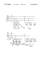
- FIG. 1 shows a prior art three phase rectifier based on single phase rectifiers.
- FIG. 2 shows a three-phase rectifier with means for achieving an artificial neutral point.
- FIG. 3 shows a first embodiment of the invention used with a three-phase system.
- FIG. 4 shows a second embodiment of the invention used with a three-phase system.
- FIG. 5 shows a third embodiment of the invention used with a three-phase system.
- FIG. 6 shows a fourth embodiment of the invention used with a three-phase system.
- FIGS. 7 and 8 show a two-phase rectifier according to two other embodiments of the invention.
- FIGS. 9A-9G are phase diagrams illustrating the inventive idea.
- FIG. 1 shows a prior art three phase rectifier based on single phase rectifiers.
- the first primary terminal of three single phase rectifiers 1 , 3 , 5 are connected to the three phases R, S, T of a three phase network.
- the second primary terminals are interconnected, that is, the rectifiers are connected in a star configuration.
- the neutral conductor N must be connected, as shown in the Figure.
- phase voltage of each phase is indicated schematically by a voltage generator, 7 , 9 , 11 , respectively.
- FIG. 2 shows a three phase rectifier similar to the one shown in FIG. 1 .
- the first primary terminal of three single phase rectifiers 21 , 23 , 25 are connected to the three phases R 1 , S 1 , T 1 of a three phase network.
- the secondary terminal are interconnected to form an artificial neutral point NL 1 .
- the neutral conductor N 1 of the network is not connected.
- the phase voltages are represented by a voltage generator, 27 , 29 , 31 , respectively, for each phase.
- An artificial neutral point creation (ANP) means A 1 is connected in parallel with the rectifiers 21 , 23 , 25 .
- the balancing means Al comprises three impedances 33 , 35 , 37 , one of said impedances 33 , 35 , 37 connected in parallel with each rectifier 21 , 23 , 25 .
- the output terminals of the impedances 33 , 35 , 37 are interconnected to form an artificial neutral point NA 1 .
- FIG. 3 shows a three phase rectifier according to a first preferred embodiment of the invention.
- three single phase rectifiers 101 , 103 , 105 are connected to the three phases R 2 , S 2 , T 2 of a three phase network.
- the neutral conductor N 2 of the three-phase network is not available, or not connected.
- the secondary terminal of the rectifiers 101 , 103 , 105 are interconnected in a point NL 2 .
- Three voltage sources 107 , 109 , 111 represent the voltage on the phases R 2 , S 2 , T 2 , respectively.
- An ANP unit A 2 comprising three small transformers 113 , 115 , 117 provides the artificial neutral point NA 2 , which is connected to the interconnected second primary terminals of the rectifiers 101 , 103 , 105 .
- the primary windings of the transformers 113 , 115 , 117 are interconnected in a star configuration. One end of each primary winding is connected to each of the phases R 2 , S 2 , T 2 , respectively.
- the secondary windings are serially connected in an open delta connection.
- the neutral potential will be positioned in the centre of gravity of a triangle built of the phase voltage vectors, that is, the phase voltage vector sum will be zero. This will be explained in more detail below.
- FIG. 4 shows a three phase rectifier according to a second preferred embodiment of the invention.
- there is a three phase system with three rectifiers 151 , 153 , 155 , a first terminal of one rectifier connected to each phase R 3 , S 3 , T 3 , respectively and second terminals of the three rectifiers 151 , 153 , 155 interconnected in a point NL 3 .
- the neutral conductor N 3 is not connected.
- the phase voltages are represented by a voltage generator, 157 , 159 , 161 , respectively, for each phase. As in FIG.
- an ANP means A 3 is connected, which in this embodiment comprises a first, a second and a third one phase transformers 163 , 165 , 167 , respectively, each having a first and a second winding on a separate core. All windings have the same number of turns.
- each phase R 3 , S 3 , T 3 is connected to the artificial neutral point NA 3 through one winding of one transformer and one winding of another transformer in the opposite direction, in a so called zigzag coupling.
- the windings are in the example shown in FIG. 4, the R phase R 3 is connected through the first winding of the second transformer 165 and the second winding of the first transformer 163 .
- the S phase S 3 is connected through the first winding of the third transformer 167 and the second winding of the second transformer 165 .
- the T phase T 3 is connected through the first winding of the first transformer 163 and the second winding of the third transformer 167 .
- the selection of first and second windings may be made arbitrarily, as long as each phase is connected through two different transformers.
- FIG. 5 shows a three phase rectifier according to a third preferred embodiment of the invention.
- a three phase system with three rectifiers 201 , 203 , 205 , a first terminal of one rectifier connected to each phase R 4 , S 4 , T 4 , respectively and second terminals of the three rectifiers 201 , 203 , 205 interconnected in a point NL 4 .
- the neutral conductor N 4 is not connected.
- the phase voltages are represented by a voltage generator, 207 , 209 , 211 , respectively, for each phase.
- an ANP means A 4 is connected, which in this embodiment comprises a three-phase inductor 213 with a core 215 comprising three legs with a winding on each leg. Each winding is connected to the respective phase R 4 , S 4 , T 4 , and the windings are interconnected to form an artificial neutral point NA 4 .
- the inductor 213 behaves in the same way as three transformers in situations where the sum of the phase voltages is zero. If a zero sequence component occurs in the voltages, the corresponding flux cannot close through the core 215 but must close in the surrounding air. The magnetization impedance of this zero sequence component is so low that the inductor 213 will function as if it were short circuited for this component. In this case the core 215 will cause the same type of effect that was caused by the serially connected secondary windings in the embodiment shown in FIG. 3 .
- FIG. 6 shows a fourth embodiment of the invention applied to a three phase system.
- a three phase system with three rectifiers 251 , 253 , 255 , a first terminal of one rectifier connected to each phase R 5 , S 5 , T 5 , respectively and second terminals of the three rectifiers 251 , 253 , 255 interconnected in a point NL 5 .
- the neutral conductor N 5 is not connected.
- the phase voltages are represented by a voltage generator, 257 , 259 , 261 , respectively, for each phase. As in FIG.
- an ANP means A 5 is connected, which in this embodiment comprises a three-phase transformer 263 with a core 265 comprising three legs 267 , 269 , 271 with a primary and a secondary winding on each of the three legs 267 , 269 , 271 .
- Each primary winding is connected to the respective phase R 5 , S 5 , T 5 .
- the secondary windings are serially connected in a delta configuration.
- the primary windings are interconnected in a star configuration to form an artificial neutral point NA 5 .
- FIG. 7 shows an embodiment similar to the one shown in FIG. 5, applied to a two-phase system, for example with two 200V rectifiers serially connected to form a main voltage of 400V. The apparatus then causes the input voltages of the rectifiers to be equal.
- a first 301 and a second 303 rectifier are connected to phase R 6 and S 6 , respectively and their second primary terminals are interconnected in a point NL 6 .
- the neutral conductor N 6 is not connected.
- the phase voltages are represented by voltage generators 307 , 309 .
- a balancing means A 6 is connected in parallel with the rectifiers 301 , 303 .
- the balancing means comprises a first 311 and a second 313 winding on the same core 315 .
- An artificial neutral point NA 6 is created between the windings, and is connected to the secondary side of the rectifiers 301 , 303 .
- FIG. 8 shows an embodiment similar to the one shown in FIG. 3, applied to a two phase system.
- a rectifier 401 and 403 respectively, is connected to each of the phases R 7 , S 7 .
- the second primary terminals of the rectifiers 401 , 403 are interconnected, to form a neutral point NL 7 .
- the voltages on the two phases R 7 , S 7 are represented by voltage generators 407 , 409 .
- the neutral conductor N 7 is not connected.
- a balancing means A 7 is connected, comprising two transformers 413 , 415 . Each one of the primary windings of the two transformers 413 , 415 is connected to one of the phases, and they are interconnected to form an artificial neutral point NA 7 .
- the secondary windings are serially connected.
- the potential of the neutral point NL of the rectifiers may differ from the potential at the neutral point of the supply network, so that the phase voltages across the rectifiers will constitute an asymmetric vector system.
- the function of the invention in the case of such an asymmetric three phase vector system of phase voltages, UR, US, UT will be analysed using theory for symmetric components.
- the voltage of each phase may be represented by three voltage components: a positive sequence, a negative sequence and a zero sequence component, respectively.
- the positive sequence components having the phase sequence R, S, T, the negative sequence components for which the phase sequence is R, T, S, and the zero sequence components which is equal in size and phase in all three phase, as shown in FIGS. 9 a, b and c.
- phase voltages in a three-phase system constitute a positive sequence vector system
- vector sum can be expressed as:
- UR+, US+ and UT+ being the respective phase voltages in a positive sequence system in which the phase difference between the phases is 120°.
- no voltage is induced in the secondary windings of FIG. 3 .
- No current will flow in the secondary windings of the transformers 113 , 115 , 117 of FIG. 3, and the impedance of the transformers will be very high, corresponding to the magnetization impedance.
- phase voltages are a negative sequence vector system UR ⁇ , US ⁇ , UT ⁇ with a 120° phase difference between the phases, the vector sum is also 0, as shown in FIG. 9 B.
- no voltage is induced in the secondary windings of the transformers 113 , 115 , 117 .
- the impedance of the transformers will be very high, corresponding to the magnetization impedance.
- FIG. 9C shows a zero sequence vector system UR 0 , US 0 , UT 0 , in which the secondary voltages have the same phase and thus add up. In this case, a current will flow in the secondary windings of the transformers, which will be short-circuited.
- Each transformer has a short circuit impedance at its primary side which is generally much lower than the input impedance of the rectifiers.
- phase voltages constitute a combination of positive sequence and negative sequence vector systems, they have different sizes, and the phase angle between them is no longer 120°, but their vector sum is still equal to zero.
- phase voltages constitute combination of the positive sequence, negative sequence and zero sequence vector systems of FIGS. 9A, 9 B and 9 C.
- the three phase voltages are then:
- phase voltages then have different sizes and the phase angle between them is no longer 120°. Their sum is equal to three times the zero sequence component, that is, 3 ⁇ U 0 , as shown in FIG. 9 E.
- Each transformer 113 , 115 , 117 has a short circuit impedance at its primary side which is generally much lower than the input impedance of the rectifiers.
- the neutral point can be given a potential such that the phase voltages UR, US, UT comprise positive sequence, negative sequence and zero sequence components, as shown in FIGS. 9D and 9E.
- FIG. 9F shows a system in which the phase voltages are a combination of a positive sequence component from the supply system and a zero sequence component caused by differences in the rectifiers.
- the phase diagram forms a triangle RST, with the neutral point NL located in the triangle, but not in its centre of gravity.
- FIG. 9G shows the same system after a balancing unit like the one shown in FIG. 3 or FIG. 5 is connected.
- the balancing unit creates an artificial neutral point N′L to which the zero sequence component has a low impedance connection while the positive sequence and negative sequence components have high impedance connections.
- Connecting the balancing unit A 2 , A 3 , A 4 , A 5 does not affect positive and negative sequence components, that is, it does not affect the supply system, which constitutes a positive sequence system. Any zero sequence components are short circuited, except for the short circuit impedance of each transformer. This implies that when a balancing unit A 2 , A 3 , A 4 , A 5 is connected, NL is shifted to N′L as shown in FIG. 9 G. The potential of the neutral point of the rectifiers NL is shifted to N′L so that the sum of the phase voltages becomes zero.
- phase voltages become as equal as the main voltages URS, UST, UTR between the phases R and S, S and T, and T and R, respectively will allow. In a positive sequence system they become equal.
- phase voltages cannot oscillate, as the potential of the neutral point is fixed.
- the third harmonic component and its multiples in the neutral point potential having the same phase in all three phases, are short circuited in the same way as the zero sequence component.
- the artificial neutral point in a three phase system functions in a similar way as the neutral point of the supply system, providing the short circuit impedance of the transformer is sufficiently low that the current does not cause a significant voltage drop.
Landscapes
- Engineering & Computer Science (AREA)
- Power Engineering (AREA)
- Rectifiers (AREA)
- Supply And Distribution Of Alternating Current (AREA)
Abstract
Description
Claims (7)
Applications Claiming Priority (3)
| Application Number | Priority Date | Filing Date | Title |
|---|---|---|---|
| SE9801583A SE513879C2 (en) | 1998-05-06 | 1998-05-06 | Multiphase rectifier device to create a stable zero point in an electrical system |
| SE9801583 | 1998-05-06 | ||
| PCT/SE1999/000744 WO1999057800A1 (en) | 1998-05-06 | 1999-05-04 | Device for creating a neutral point in an electrical system |
Publications (1)
| Publication Number | Publication Date |
|---|---|
| US6466466B1 true US6466466B1 (en) | 2002-10-15 |
Family
ID=20411205
Family Applications (1)
| Application Number | Title | Priority Date | Filing Date |
|---|---|---|---|
| US09/674,573 Expired - Lifetime US6466466B1 (en) | 1998-05-06 | 1999-05-04 | Stable artificial neutral point in a three phase network of single phase rectifiers |
Country Status (12)
| Country | Link |
|---|---|
| US (1) | US6466466B1 (en) |
| EP (1) | EP1078446A1 (en) |
| JP (1) | JP2002514039A (en) |
| CN (1) | CN1308787A (en) |
| AU (1) | AU4304899A (en) |
| BR (1) | BR9910223A (en) |
| CA (1) | CA2331648A1 (en) |
| HU (1) | HUP0101967A2 (en) |
| RU (1) | RU2000130722A (en) |
| SE (1) | SE513879C2 (en) |
| TR (1) | TR200003210T2 (en) |
| WO (1) | WO1999057800A1 (en) |
Cited By (13)
| Publication number | Priority date | Publication date | Assignee | Title |
|---|---|---|---|---|
| DE10317114A1 (en) * | 2003-04-14 | 2004-10-28 | BSH Bosch und Siemens Hausgeräte GmbH | Circuit for providing neutral conductor in three-phase electrical appliance, e.g. cooker, has three inductances connected to phase lines in star shape, providing neutral line at node point |
| US20060197511A1 (en) * | 2003-06-27 | 2006-09-07 | Af Klercker Alakula Mats | Transformer with protection against direct current magnetization caused by zero sequence current |
| US20060250207A1 (en) * | 2005-05-03 | 2006-11-09 | Mte Corporation | Multiple three-phase inductor with a common core |
| US20070217103A1 (en) * | 2004-05-10 | 2007-09-20 | Forskarpatent I Syd Ab | Method and equipment for the protection of power systems against geomagnetically induced currents |
| US20090034305A1 (en) * | 2005-12-26 | 2009-02-05 | Abdallah Mechi | Power Conversion Device and Power Conversion System |
| US20100253295A1 (en) * | 2009-04-01 | 2010-10-07 | Delta Electronics, Inc. | Single-phase and three-phase dual buck-boost/buck power factor correction circuits and controlling method thereof |
| KR101133138B1 (en) | 2007-06-13 | 2012-04-06 | 삼성테크윈 주식회사 | Power converter system |
| US20120262966A1 (en) * | 2010-01-11 | 2012-10-18 | Koninklijke Philips Electronics N.V. | Ac/dc converter circuit |
| US20130207623A1 (en) * | 2010-10-19 | 2013-08-15 | Kwok Tung Wong | Power Supply Device for a Nonlinear, Time-Varying Load |
| EP2940821A1 (en) * | 2014-04-28 | 2015-11-04 | Rockwell Automation Technologies, Inc. | Calculating line-to-neutral voltages without a connection to a system neutral or earth ground |
| EP2975727A1 (en) * | 2014-07-17 | 2016-01-20 | ABB Technology AG | Three-wire UPS system with artificial neutral |
| CN108206642A (en) * | 2016-12-20 | 2018-06-26 | 华为技术有限公司 | The method and apparatus adjusted for 3-phase power converter midpoint potential |
| US11014602B2 (en) * | 2016-03-04 | 2021-05-25 | Nidec Corporation | Power conversion device, motor drive unit, electric power steering device, and relay module |
Families Citing this family (5)
| Publication number | Priority date | Publication date | Assignee | Title |
|---|---|---|---|---|
| JP4699659B2 (en) | 2000-12-25 | 2011-06-15 | 新電元工業株式会社 | Multiphase rectifier |
| US6501192B1 (en) * | 2001-11-16 | 2002-12-31 | Eni Technology, Inc. | Three phase rectifier circuit with virtual neutral |
| CN102611125B (en) * | 2011-01-25 | 2016-09-07 | 华东电力试验研究院有限公司 | Asymmetry parameter three-phase three-winding transformer phantom and computational methods |
| CN102208813A (en) * | 2011-05-10 | 2011-10-05 | 艾默生网络能源有限公司 | Artificial Neutral Point (ANP) power factor correction circuit |
| JP6180825B2 (en) * | 2013-07-02 | 2017-08-16 | 株式会社日立製作所 | Power converter and electrical / mechanical energy conversion system |
Citations (7)
| Publication number | Priority date | Publication date | Assignee | Title |
|---|---|---|---|---|
| US4143414A (en) * | 1978-04-10 | 1979-03-06 | General Motors Corporation | Three phase ac to dc voltage converter with power line harmonic current reduction |
| US4443759A (en) * | 1981-05-07 | 1984-04-17 | Magnaflux Corporation | Magnetizing current supply for magnetic particle inspection with SCR's connected to three-phase secondary windings for rectification and control |
| US4513363A (en) * | 1982-02-22 | 1985-04-23 | Medar, Inc. | Structure for and method of reducing impedance in multiphase direct current power supplies |
| US5311419A (en) * | 1992-08-17 | 1994-05-10 | Sundstrand Corporation | Polyphase AC/DC converter |
| WO1994027357A1 (en) | 1993-05-11 | 1994-11-24 | Swichtec Power Systems Limited | A power converter with star configured modules |
| US5574356A (en) | 1994-07-08 | 1996-11-12 | Northrop Grumman Corporation | Active neutral current compensator |
| US5894414A (en) * | 1997-03-03 | 1999-04-13 | Lucent Technologies Inc. | Three phase rectifier using three single phase converters and a single DC/DC converter |
-
1998
- 1998-05-06 SE SE9801583A patent/SE513879C2/en unknown
-
1999
- 1999-05-04 CA CA002331648A patent/CA2331648A1/en not_active Abandoned
- 1999-05-04 WO PCT/SE1999/000744 patent/WO1999057800A1/en not_active Application Discontinuation
- 1999-05-04 HU HU0101967A patent/HUP0101967A2/en unknown
- 1999-05-04 RU RU2000130722/09A patent/RU2000130722A/en not_active Application Discontinuation
- 1999-05-04 BR BR9910223-4A patent/BR9910223A/en not_active Application Discontinuation
- 1999-05-04 TR TR2000/03210T patent/TR200003210T2/en unknown
- 1999-05-04 JP JP2000547688A patent/JP2002514039A/en active Pending
- 1999-05-04 AU AU43048/99A patent/AU4304899A/en not_active Abandoned
- 1999-05-04 US US09/674,573 patent/US6466466B1/en not_active Expired - Lifetime
- 1999-05-04 EP EP99948573A patent/EP1078446A1/en not_active Withdrawn
- 1999-05-04 CN CN99808272.4A patent/CN1308787A/en active Pending
Patent Citations (8)
| Publication number | Priority date | Publication date | Assignee | Title |
|---|---|---|---|---|
| US4143414A (en) * | 1978-04-10 | 1979-03-06 | General Motors Corporation | Three phase ac to dc voltage converter with power line harmonic current reduction |
| US4443759A (en) * | 1981-05-07 | 1984-04-17 | Magnaflux Corporation | Magnetizing current supply for magnetic particle inspection with SCR's connected to three-phase secondary windings for rectification and control |
| US4513363A (en) * | 1982-02-22 | 1985-04-23 | Medar, Inc. | Structure for and method of reducing impedance in multiphase direct current power supplies |
| US5311419A (en) * | 1992-08-17 | 1994-05-10 | Sundstrand Corporation | Polyphase AC/DC converter |
| WO1994027357A1 (en) | 1993-05-11 | 1994-11-24 | Swichtec Power Systems Limited | A power converter with star configured modules |
| US5757637A (en) * | 1993-05-11 | 1998-05-26 | Switchtec Power Systems Limited | Power converter with star configured modules |
| US5574356A (en) | 1994-07-08 | 1996-11-12 | Northrop Grumman Corporation | Active neutral current compensator |
| US5894414A (en) * | 1997-03-03 | 1999-04-13 | Lucent Technologies Inc. | Three phase rectifier using three single phase converters and a single DC/DC converter |
Cited By (23)
| Publication number | Priority date | Publication date | Assignee | Title |
|---|---|---|---|---|
| DE10317114A1 (en) * | 2003-04-14 | 2004-10-28 | BSH Bosch und Siemens Hausgeräte GmbH | Circuit for providing neutral conductor in three-phase electrical appliance, e.g. cooker, has three inductances connected to phase lines in star shape, providing neutral line at node point |
| US20060197511A1 (en) * | 2003-06-27 | 2006-09-07 | Af Klercker Alakula Mats | Transformer with protection against direct current magnetization caused by zero sequence current |
| US7432699B2 (en) * | 2003-06-27 | 2008-10-07 | Forskarpatent I Syd Ab | Transformer with protection against direct current magnetization caused by zero sequence current |
| US20070217103A1 (en) * | 2004-05-10 | 2007-09-20 | Forskarpatent I Syd Ab | Method and equipment for the protection of power systems against geomagnetically induced currents |
| US7489485B2 (en) | 2004-05-10 | 2009-02-10 | Forskarpatent I Syd Ab | Method and equipment for the protection of power systems against geomagnetically induced currents |
| US20060250207A1 (en) * | 2005-05-03 | 2006-11-09 | Mte Corporation | Multiple three-phase inductor with a common core |
| US7142081B1 (en) | 2005-05-03 | 2006-11-28 | Mte Corporation | Multiple three-phase inductor with a common core |
| US20090034305A1 (en) * | 2005-12-26 | 2009-02-05 | Abdallah Mechi | Power Conversion Device and Power Conversion System |
| KR101133138B1 (en) | 2007-06-13 | 2012-04-06 | 삼성테크윈 주식회사 | Power converter system |
| US8705254B2 (en) * | 2009-04-01 | 2014-04-22 | Delta Electronics, Inc. | Single-phase and three-phase dual buck-boost/buck power factor correction circuits and controlling method thereof |
| US20100253295A1 (en) * | 2009-04-01 | 2010-10-07 | Delta Electronics, Inc. | Single-phase and three-phase dual buck-boost/buck power factor correction circuits and controlling method thereof |
| US20120262966A1 (en) * | 2010-01-11 | 2012-10-18 | Koninklijke Philips Electronics N.V. | Ac/dc converter circuit |
| US9425703B2 (en) * | 2010-01-11 | 2016-08-23 | Koninklijke Philips N.V. | AC/DC converter circuit for common three-phase AC input voltages and method of operating such converter circuit |
| US20130207623A1 (en) * | 2010-10-19 | 2013-08-15 | Kwok Tung Wong | Power Supply Device for a Nonlinear, Time-Varying Load |
| US9285817B2 (en) * | 2010-10-19 | 2016-03-15 | Siemens Aktiengesellschaft | Power supply device for a nonlinear, time-varying load |
| RU2578204C2 (en) * | 2010-10-19 | 2016-03-27 | Сименс Акциенгезелльшафт | Power supply device for non-linear time-varying load |
| EP2940821A1 (en) * | 2014-04-28 | 2015-11-04 | Rockwell Automation Technologies, Inc. | Calculating line-to-neutral voltages without a connection to a system neutral or earth ground |
| CN105044426A (en) * | 2014-04-28 | 2015-11-11 | 洛克威尔自动控制技术股份有限公司 | Calculating line-to-neutral voltages without a connection to a system neutral or earth ground |
| CN105044426B (en) * | 2014-04-28 | 2020-01-31 | 罗克韦尔自动化技术公司 | Calculating line-to-neutral voltage without connecting system neutral or ground |
| EP2975727A1 (en) * | 2014-07-17 | 2016-01-20 | ABB Technology AG | Three-wire UPS system with artificial neutral |
| US11014602B2 (en) * | 2016-03-04 | 2021-05-25 | Nidec Corporation | Power conversion device, motor drive unit, electric power steering device, and relay module |
| CN108206642A (en) * | 2016-12-20 | 2018-06-26 | 华为技术有限公司 | The method and apparatus adjusted for 3-phase power converter midpoint potential |
| CN108206642B (en) * | 2016-12-20 | 2020-02-14 | 华为技术有限公司 | Method and device for adjusting the neutral point potential of a three-phase current transformer |
Also Published As
| Publication number | Publication date |
|---|---|
| EP1078446A1 (en) | 2001-02-28 |
| CA2331648A1 (en) | 1999-11-11 |
| SE513879C2 (en) | 2000-11-20 |
| AU4304899A (en) | 1999-11-23 |
| WO1999057800A1 (en) | 1999-11-11 |
| CN1308787A (en) | 2001-08-15 |
| RU2000130722A (en) | 2002-11-27 |
| JP2002514039A (en) | 2002-05-14 |
| TR200003210T2 (en) | 2001-05-21 |
| BR9910223A (en) | 2001-01-09 |
| SE9801583D0 (en) | 1998-05-06 |
| SE9801583L (en) | 1999-11-07 |
| HUP0101967A2 (en) | 2001-09-28 |
Similar Documents
| Publication | Publication Date | Title |
|---|---|---|
| US6466466B1 (en) | Stable artificial neutral point in a three phase network of single phase rectifiers | |
| US7277302B2 (en) | 12-pulse converter including a filter choke incorporated in the rectifier | |
| US7233506B1 (en) | Low kVA/kW transformers for AC to DC multipulse converters | |
| US5124904A (en) | Optimized 18-pulse type AC/DC, or DC/AC, converter system | |
| US6101113A (en) | Transformers for multipulse AC/DC converters | |
| US7274280B1 (en) | Nine-phase step-up/step-down autotransformer | |
| US7609536B2 (en) | Autotransformer AC/DC converter | |
| US7474188B2 (en) | 40° phase-shifting autotransformer | |
| EP0716496B1 (en) | Three-phase brushless self-excited synchronous generator with no rotor excitation windings | |
| US6249443B1 (en) | Nine-phase transformer | |
| US5781428A (en) | Transformer for 12-pulse series connection of converters | |
| US4493016A (en) | Rectifier transformer | |
| US3671901A (en) | Anti-harmonic transformer | |
| US6982884B1 (en) | Autotransformers to parallel AC to DC converters | |
| EP0472267B1 (en) | Optimized, 18-pulse type AC/DC, or DC/AC, converter system | |
| US9966868B2 (en) | Three-phase to nine-phase autotransformer | |
| EP3975210A1 (en) | Three-phase magnetics assembly with unified core body | |
| EP3934083A1 (en) | Isolated multi-phase dc/dc converter with reduced quantity of blocking capacitors | |
| US11120939B2 (en) | Ten-phase auto transformer rectifier unit | |
| JPH1132437A (en) | Three-phase four-wire low voltage distribution system | |
| KR100534144B1 (en) | a device of decreasing harmonic with keep improve the balance of voltage and current | |
| JPH11266586A (en) | Ac-to-dc power converter | |
| MXPA00010757A (en) | Device for creating a neutral point in an electrical system | |
| US1979699A (en) | Balance coil | |
| KR200338373Y1 (en) | a device of decreasing harmonic with keep improve the balance of voltage and current |
Legal Events
| Date | Code | Title | Description |
|---|---|---|---|
| AS | Assignment |
Owner name: TELEFONAKTIEBOLAGET L. M. ERICSON, SWEDEN Free format text: ASSIGNMENT OF ASSIGNORS INTEREST;ASSIGNORS:KARLSSON, MATS;WOLPERT, TADEUS;REEL/FRAME:011433/0832;SIGNING DATES FROM 20001214 TO 20001218 |
|
| STCF | Information on status: patent grant |
Free format text: PATENTED CASE |
|
| AS | Assignment |
Owner name: EMERSON ENERGY SYSTEMS AB, SWEDEN Free format text: ASSIGNMENT OF ASSIGNORS INTEREST;ASSIGNOR:TELEFONAKTIEBOLAGET LM ERICSSON (PUBL);REEL/FRAME:014215/0180 Effective date: 20001130 |
|
| FPAY | Fee payment |
Year of fee payment: 4 |
|
| AS | Assignment |
Owner name: EMERSON NETWORK POWER, ENERGY SYSTEMS, NORTH AMERI Free format text: ASSIGNMENT OF ASSIGNORS INTEREST;ASSIGNOR:EMERSON NETWORK POWER ENERGY SYSTEMS AB;REEL/FRAME:023401/0383 Effective date: 20080718 Owner name: EMERSON NETWORK POWER ENERGY SYSTEMS AB, SWEDEN Free format text: CHANGE OF NAME;ASSIGNOR:EMERSON ENERGY SYSTEMS AB;REEL/FRAME:023401/0355 Effective date: 20041002 |
|
| FPAY | Fee payment |
Year of fee payment: 8 |
|
| FPAY | Fee payment |
Year of fee payment: 12 |
|
| AS | Assignment |
Owner name: JPMORGAN CHASE BANK, N.A., AS COLLATERAL AGENT, NE Free format text: SECURITY AGREEMENT;ASSIGNORS:ALBER CORP.;ASCO POWER TECHNOLOGIES, L.P.;AVOCENT CORPORATION;AND OTHERS;REEL/FRAME:040783/0148 Effective date: 20161130 Owner name: JPMORGAN CHASE BANK, N.A., AS COLLATERAL AGENT, NEW YORK Free format text: SECURITY AGREEMENT;ASSIGNORS:ALBER CORP.;ASCO POWER TECHNOLOGIES, L.P.;AVOCENT CORPORATION;AND OTHERS;REEL/FRAME:040783/0148 Effective date: 20161130 |
|
| AS | Assignment |
Owner name: JPMORGAN CHASE BANK, N.A., AS COLLATERAL AGENT, NE Free format text: SECURITY AGREEMENT;ASSIGNORS:ALBER CORP.;ASCO POWER TECHNOLOGIES, L.P.;AVOCENT CORPORATION;AND OTHERS;REEL/FRAME:040797/0615 Effective date: 20161130 Owner name: JPMORGAN CHASE BANK, N.A., AS COLLATERAL AGENT, NEW YORK Free format text: SECURITY AGREEMENT;ASSIGNORS:ALBER CORP.;ASCO POWER TECHNOLOGIES, L.P.;AVOCENT CORPORATION;AND OTHERS;REEL/FRAME:040797/0615 Effective date: 20161130 |
|
| AS | Assignment |
Owner name: VERTIV ENERGY SYSTEMS, INC., ILLINOIS Free format text: CHANGE OF NAME;ASSIGNOR:EMERSON NETWORK POWER, ENGERGY SYSTEMS, NORTH AMERICA, INC.;REEL/FRAME:047091/0638 Effective date: 20170403 |
|
| AS | Assignment |
Owner name: VERTIV ENERGY SYSTEMS, INC., ILLINOIS Free format text: CORRECTIVE ASSIGNMENT TO CORRECT THE ASSIGNORS NAME PREVIOUSLY RECORDED AT REEL: 047091 FRAME: 0638. ASSIGNOR(S) HEREBY CONFIRMS THE CHANGE OF NAME;ASSIGNOR:EMERSON NETWORK POWER, ENERGY SYSTEMS, NORTH AMERICA, INC.;REEL/FRAME:047210/0260 Effective date: 20170403 |
|
| AS | Assignment |
Owner name: THE BANK OF NEW YORK MELLON TRUST COMPANY, N.A., T Free format text: SECOND LIEN SECURITY AGREEMENT;ASSIGNORS:VERTIV IT SYSTEMS, INC.;VERTIV CORPORATION;VERTIV NORTH AMERICA, INC.;AND OTHERS;REEL/FRAME:049415/0262 Effective date: 20190513 Owner name: THE BANK OF NEW YORK MELLON TRUST COMPANY, N.A., TEXAS Free format text: SECOND LIEN SECURITY AGREEMENT;ASSIGNORS:VERTIV IT SYSTEMS, INC.;VERTIV CORPORATION;VERTIV NORTH AMERICA, INC.;AND OTHERS;REEL/FRAME:049415/0262 Effective date: 20190513 |
|
| AS | Assignment |
Owner name: VERTIV IT SYSTEMS, INC. (F/K/A AVOCENT REDMOND CORP.), OHIO Free format text: RELEASE BY SECURED PARTY;ASSIGNOR:JPMORGAN CHASE BANK, N.A.;REEL/FRAME:052065/0666 Effective date: 20200302 Owner name: VERTIV CORPORATION (F/K/A EMERSON NETWORK POWER, ENERGY SYSTEMS, NORTH AMERICA, INC.), OHIO Free format text: RELEASE BY SECURED PARTY;ASSIGNOR:JPMORGAN CHASE BANK, N.A.;REEL/FRAME:052065/0666 Effective date: 20200302 Owner name: VERTIV CORPORATION (F/K/A LIEBERT CORPORATION), OHIO Free format text: RELEASE BY SECURED PARTY;ASSIGNOR:JPMORGAN CHASE BANK, N.A.;REEL/FRAME:052065/0666 Effective date: 20200302 Owner name: VERTIV IT SYSTEMS, INC. (F/K/A AVOCENT FREMONT, LLC), OHIO Free format text: RELEASE BY SECURED PARTY;ASSIGNOR:JPMORGAN CHASE BANK, N.A.;REEL/FRAME:052065/0666 Effective date: 20200302 Owner name: VERTIV CORPORATION (F/K/A ALBER CORP.), OHIO Free format text: RELEASE BY SECURED PARTY;ASSIGNOR:JPMORGAN CHASE BANK, N.A.;REEL/FRAME:052065/0666 Effective date: 20200302 Owner name: VERTIV IT SYSTEMS, INC. (F/K/A AVOCENT HUNTSVILLE, LLC), OHIO Free format text: RELEASE BY SECURED PARTY;ASSIGNOR:JPMORGAN CHASE BANK, N.A.;REEL/FRAME:052065/0666 Effective date: 20200302 Owner name: VERTIV IT SYSTEMS, INC. (F/K/A AVOCENT CORPORATION), OHIO Free format text: RELEASE BY SECURED PARTY;ASSIGNOR:JPMORGAN CHASE BANK, N.A.;REEL/FRAME:052065/0666 Effective date: 20200302 Owner name: ELECTRICAL RELIABILITY SERVICES, INC., OHIO Free format text: RELEASE BY SECURED PARTY;ASSIGNOR:JPMORGAN CHASE BANK, N.A.;REEL/FRAME:052065/0666 Effective date: 20200302 Owner name: VERTIV IT SYSTEMS, INC., OHIO Free format text: RELEASE BY SECURED PARTY;ASSIGNOR:THE BANK OF NEW YORK MELLON TRUST COMPANY N.A.;REEL/FRAME:052071/0913 Effective date: 20200302 Owner name: VERTIV CORPORATION, OHIO Free format text: RELEASE BY SECURED PARTY;ASSIGNOR:THE BANK OF NEW YORK MELLON TRUST COMPANY N.A.;REEL/FRAME:052071/0913 Effective date: 20200302 Owner name: ELECTRICAL RELIABILITY SERVICES, INC., OHIO Free format text: RELEASE BY SECURED PARTY;ASSIGNOR:THE BANK OF NEW YORK MELLON TRUST COMPANY N.A.;REEL/FRAME:052071/0913 Effective date: 20200302 |
|
| AS | Assignment |
Owner name: CITIBANK, N.A., NEW YORK Free format text: SECURITY AGREEMENT;ASSIGNORS:ELECTRICAL RELIABILITY SERVICES, INC.;ENERGY LABS, INC.;VERTIV CORPORATION;AND OTHERS;REEL/FRAME:052076/0874 Effective date: 20200302 |