US5757633A - High efficiency multistep sinewave synthesizer - Google Patents
High efficiency multistep sinewave synthesizer Download PDFInfo
- Publication number
- US5757633A US5757633A US08/755,847 US75584796A US5757633A US 5757633 A US5757633 A US 5757633A US 75584796 A US75584796 A US 75584796A US 5757633 A US5757633 A US 5757633A
- Authority
- US
- United States
- Prior art keywords
- output
- output line
- inverter
- voltage
- bridge circuit
- Prior art date
- Legal status (The legal status is an assumption and is not a legal conclusion. Google has not performed a legal analysis and makes no representation as to the accuracy of the status listed.)
- Expired - Lifetime
Links
Images


Classifications
-
- H—ELECTRICITY
- H02—GENERATION; CONVERSION OR DISTRIBUTION OF ELECTRIC POWER
- H02M—APPARATUS FOR CONVERSION BETWEEN AC AND AC, BETWEEN AC AND DC, OR BETWEEN DC AND DC, AND FOR USE WITH MAINS OR SIMILAR POWER SUPPLY SYSTEMS; CONVERSION OF DC OR AC INPUT POWER INTO SURGE OUTPUT POWER; CONTROL OR REGULATION THEREOF
- H02M7/00—Conversion of ac power input into dc power output; Conversion of dc power input into ac power output
- H02M7/42—Conversion of dc power input into ac power output without possibility of reversal
- H02M7/44—Conversion of dc power input into ac power output without possibility of reversal by static converters
- H02M7/48—Conversion of dc power input into ac power output without possibility of reversal by static converters using discharge tubes with control electrode or semiconductor devices with control electrode
- H02M7/483—Converters with outputs that each can have more than two voltages levels
- H02M7/49—Combination of the output voltage waveforms of a plurality of converters
Definitions
- the present invention relates to sinewave synthesizers, and more particularly to a multistep inverter capable of efficiently converting a direct current (dc) signal into an alternating current (ac) signal with low harmonic distortion without the use of large output filters.
- a transistor e.g., a field effect transistor (FET) switches on and off to produce pulses of constant amplitude but of varying widths, i.e., durations.
- the width of each pulse is proportional to the amplitude of the portion of the waveform or signal being approximated.
- the amplitude of the pulses, although constant, must be of sufficient magnitude to approximate the desired signal. Therefore, prior art sinewave synthesizers which used pulse width modulation to approximate an entire sine wave required pulses of relatively large amplitudes in order to approximate the peaks of the sine waves.
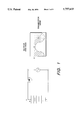
- FIG. 1 shows how a transistor operating in the linear region can produce a pure sine wave from a dc source. As shown in FIG. 1, the transistor drop during the lowest point of the sine wave is equal to the peak-to-peak amplitude of the sine wave.
- Prior art sinewave synthesizers which used discrete voltage steps to piecewise approximate a sine wave did not further employ pulse width modulation of the discrete voltage steps to improve the sine wave as in the present invention. Therefore, prior art sinewave synthesizers exhibited poor harmonic distortion characteristics and required large output filter circuits to improve the output waveform. These large output filters are typically relatively heavy and require a large amount of space. In particular, some applications of sinewave synthesizers, e.g., a power supply for a commercial or military aircraft, require that the size and weight of the sinewave synthesizer be kept as small as possible. If a heavy and large output filter must be used with the sinewave synthesizer in order to filter out the unwanted harmonic components, then such sinewave synthesizer is not well suited for such light weight and small size applications.
- a sinewave synthesizer capable of more efficiently producing a high quality sine wave with low harmonic distortion and low electromagnetic interference (EMI) susceptibility, without the need for large output filters to improve the output waveform.
- EMI electromagnetic interference
- the present invention addresses the above and other needs by providing a multistep inverter that uses multiple inverter bridges connected in series to piecewise approximate a sine wave.
- the inverter bridges are bypassed or switched into service as required for sinewave synthesis. After a step is switched in, it creates its portion of the sine wave.
- Each step is further smoothed using pulse width modulation which leads to a smoother sine wave with the consequent advantages of lower distortion, smaller and lighter filtering circuits, and lower conversion losses during transistor switching.
- the present invention can be characterized as a multi-step inverter for converting dc power to ac power.
- the multistep inverter employs a primary inverter for converting a source of dc power to an intermediate ac power signal; a transformer for coupling the intermediate ac power signal to a plurality of secondary windings, a rectifier coupled to each secondary winding for rectifying the ac signal appearing thereat to produce a rectified secondary power signal, a plurality of secondary inverters, each having first and second output lines, for converting each rectified secondary power signal, in response to a control signal, to one of three output voltages appearing across the first and second output lines: a positive voltage +V, a zero voltage 0V, or a negative voltage -V.
- the plurality of secondary inverters are stacked together in a series circuit relationship so that the first output line of a 1st secondary inverter is connected to one side of a load, the second output line of the 1st secondary inverter is connected to the first output line of a 2d secondary inverter, the second output line of the 2d secondary inverter is connected to the first output line of a 3d secondary inverter, and so on for n different secondary inverters, where n is an integer of at least two, with the second output line of the nth secondary inverter being connected to the other side of the load.
- the multistep inverter further employs a control circuit for generating the control signal applied to each of the plurality of secondary inverters in a way that combines select combinations of the +V, 0V, and -V outputs from the plurality of secondary inverters in series across the load so that the signal applied across the load approximates a sine wave (or other desired wave shape).
- the control circuit generates the control signals applied to each of the plurality of secondary inverters so that the signal applied across the load appears, e.g., as a stair-stepped sine wave, with pulse-width modulation used to smooth each step of the sine wave.
- FIG. 1 shows a transistor operating in the linear region to produce a pure sine wave from a DC source.
- FIG. 2 shows a functional block diagram of a multistep inverter having n multistep inverter bridges connected in series.
- FIG. 3 is a circuit level diagram of one embodiment of the multistep inverter of FIG. 2.
- FIGS. 4A-4C show three possible switch states for an H-bridge circuit of the type used with the invention.
- FIG. 5 show some of the different voltage states possible with five bridges in series.
- FIG. 6 shows a simulated sine wave with twenty discrete voltage steps.
- FIG. 7 shows pulse width modulation smoothing of the voltage steps shown in FIG. 6.
- FIG. 8 is a timing waveform diagram that teaches how the control signal may be used to control a 4-state single phase inverter of the type shown in FIG. 3 in order to produce a sinusoidal-type waveform.
- FIG. 9 shows a 4-stage single phase voltage output with and without filtering used to produce a sine wave.
- FIG. 10 is a circuit level diagram of the preferred embodiment of a three phase, multistep inverter connected in a Wye configuration.
- FIG. 1 was described previously in the background portion of the application.
- FIG. 2 a functional block diagram of one embodiment of a single phase, multistep sinewave synthesizer 10 is shown.
- Primary inverter 12 receives a direct current (dc) input signal from a dc power source (not shown).
- dc direct current
- dc power source may comprise a dc power bus of, e.g., 170 vdc.
- the primary inverter 12 converts the dc input into an intermediate alternating current (ac) signal.
- This intermediate ac signal is transformer coupled to a multistep inverter 14 which consists of a plurality of secondary inverters connected in series. As shown in FIG.
- transformer coupling is accomplished by a primary transformer winding Tp and secondary transformer windings Ts1-Tsn.
- Each of the secondary transformer windings Ts1-Tsn are connected to a respective rectifier circuit 15-1, 15-2, . . . 15-n, each of which converts the transformer coupled ac signal appearing across the secondary winding Ts1-Tsn to a dc signal, within a multistep inverter 14.
- Any suitable transformer may be used to realize the primary winding Tp and each of the secondary windings Ts1-Tsn.
- the transformer may be a planar transformer, as is known in the art.
- Each of the secondary inverters of multistep inverter 14 are connected in series and, in combination, produce an ac signal that appears across a load 20.
- Each of the secondary invertors when considered alone, converts the induced ac signal across its respective secondary winding into one of three DC output voltages: a positive voltage +V, a zero voltage 0v, or a negative voltage -V. Whether the dc output voltage is positive, negative, or zero depends on the control signals received from control circuit 16. It is the combination of these dc voltages when added together in series, that creates the signal that appears across the load 20, as explained more fully below.
- control circuit 16 is electrically isolated from multistep inverter 14 by means of an optiosolator circuit 18.
- a control circuit may be designed to drive either a single 4-stage secondary inverter to produce a single-phase ac signal across a load, or alternatively such control circuit may be designed to drive three separate 4-stage secondary inverters in order to produce a three-phase ac signal across the load.
- the output terminals 17 and 19 of the multistep sinewave synthesizer 10 extend from the 1st and nth secondary inverters of multistep inverter 14.
- the load 20, which is not part of the present invention, is shown connected between the output terminals 17 and 19 of the multistep sinewave synthesizer 10.
- a high frequency filter capacitor C f may be placed across the load.
- the control circuit 16 controls the output voltages of each of the secondary inverters of multistep inverter 14 such that the signal applied across the load 20 approximates a sine wave.
- this sine wave approximation is accomplished by independently controlling the output voltage states of the secondary inverters of multistep inverter 14 such that the sum of the output voltages approximates a sine wave having multiple discrete voltage steps.
- the approximated sine wave is further smoothed to provide a high quality, low distortion sine wave.
- the primary inverter 12 includes input filter circuitry having inductors L1, L2, and L3 and capacitors C1 and C2.
- the primary inverter 12 further includes an inverter bridge, e.g., an insultated gate bipolar transistor (IGBT), for alternating the DC current input at a prescribed frequency, e.g., 100 KHz, to provide an intermediate ac signal to primary transformer winding Tp.
- IGBT bridge is comprised of four switches S1-S4 connected in an H-bridge configuration as shown in FIG. 3.
- each of the switches S1-S4 is a bipolar junction transistor having a reverse biased diode connected across the collector and emitter junctions to protect the transistors against spurious signals and reverse conduction during switching.
- Inductor L4 and capacitor C3 form a resonant circuit which resonates at the prescribed frequency to allow the IGBT's to swtich at zero voltage and reduce harmonic distortion in the ac signal provided to primary transformer winding Lp. As shown in FIG. 3, the ac signal across primary transformer winding Tp is inductively coupled to secondary windings Ts1-Ts4.
- the induced ac signals across secondary windings Ts1-Ts4 are then full-bridge rectified by rectifying circuitry connected to the leads of each of the secondary windings Ts1-Ts4.
- the rectifying circuits each consist of four diodes and a capacitor configured as shown in FIG. 3. Other rectifying circuits could also be used (e.g., using two diodes and a center-tapped secondary transformer) as are known in the art, or equivalents thereof.
- Each of the rectifying circuits rectifies the ac signal induced in the respective secondary winding to produce a dc signal that is applied to the multistep inverter bridges H1-H4 of multistep inverter 14.
- the multistep inverter 14 places multiple, full bridge circuits H1-H4, referred to herein as H-bridges, in a series circuit relationship.
- each H-bridge consists of four field effect transistors (FET's) each having a reverse biased diode connected across the source and drain to protect the transistor from spurious signals and reverse conduction during switching.
- the FET's are connected in an H-bridge configuration as shown in FIG. 3.
- Each H-bridge is independently controlled by a control circuit (not shown) to provide three output voltage states: a positive, negative, or zero voltage state as described below.
- the control circuit synchronously and selectively turns on the FET's of each H-bridge in order to provide the desired output voltage states.
- FIG. 8, described below, shows a timing waveform diagram that teaches the manner in which contral signals may be used to control the H-bridges of the multistep inverter 14 in order to produce a desired output waveform, e.g., a sine wave.
- FIGS. 4A-4C show the three possible switch states for an H-bridge.
- the dark lines with arrows are meant to show the direction of current flow through the circuit, depending on the switch states.
- switches F1 and F4 are turned on and the output voltage, i.e., the voltage appearing across output terminals 32 and 34 of the H-bridge 30 is equal to V.
- the output voltage is zero when switch F4 and diode F3 are turned on. This is because the bridge's dc voltage source is bypassed by the current flow.
- the last state, shown in FIG. 4C allows for a negative output voltage when switches F2 and F3 are turned on.
- the bypass, 0 volt, state of an H-bridge allows several H bridges to be connected in series with the resulting voltage sum being independently controlled by selecting the operating state of the individual H-bridges.
- each transistor operating in the pulse width modulation (PWM) mode need only switch 20% of the voltage for 20% of the time. This reduces the PWM switching losses per transistor by a factor of twenty five. With low switching losses, high PWM frequencies can be used to smooth each step. The combination of low PWM amplitude (20% of normal PWM) and high PWM frequency (up to 200 KHz with this design) produces a high quality sine wave with little filtering. Therefore massive filtering circuits are not required.
- FIG. 8 there is shown a timing waveform diagram that teaches how the control signal may be used to control a 4-state single phase inverter of the type shown in FIG. 3 in order to produce a sinusoidal-type waveform.
- the output voltages of each of the four H-bridge circuits H1, H2, H3 and H4 used in FIG. 3, as well as the sum of such output voltages (H1+H2+H3+H4), are illustrated as a function of time.
- such output voltages may assume one of three values depending upon the state of the respective H-bridge circuit. These three values are: +V, 0, and -V. The manner of achieving these three output voltages was explained previously in connection with FIGS. 4A-4C above.
- FIG. 8 the output voltages of each of the four H-bridge circuits H1, H2, H3 and H4 used in FIG. 3, as well as the sum of such output voltages (H1+H2+H3+H4)
- the period T of the desired output sine wave is divided into sixteen time segments, t1, t2, t3, . . . t16.
- the H-bridge circuits H2, H3, and H4 remain OFF (0 volts), and the H-bridge circuit H1 is turned ON (+V) and OFF (0 volts) in accordance with a desired pulse-width modulation (PWM) scheme for the duration of the time increment t1.
- PWM pulse-width modulation
- the PWM causes H1 to turn ON with increasingly wider positive pulses, i.e., pulses switching from 0 volts to +V volts.
- FIG. 8 Four such positive pulses 52, 53, 54, and 55 are illustrated in FIG. 8, each of increasing width.
- Such sequence of pulses when averaged, or filtered, creates an output voltage waveform 58 (heavy line) that increases in amplitude throughout the time increment t1, as shown in the bottom waveform diagram of FIG. 8 (representing the sum of the H1, H2, H3 and H4 outputs).
- FIG. 8 illustrates the sum of the H1, H2, H3 and H4 outputs.
- the H1-bridge circuit turns ON (+V output) and stays on until time t8.
- the H3- and H4-bridge circuits remain OFF (0 volts).
- the H2-bridge circuit turns ON and OFF in accordance with the desired PWM scheme with increasingly wider positive pulses. This causes the output voltage waveform 58 to continue to increase in amplitude throughout the time increment t2, with the output voltage being the sum of H1(+V), H2(+V/0v), H3(0v) and H4(0v).
- the H2-bridge circuit turns ON (+V output) and stays on until time t7.
- the H4-bridge circuit remains OFF (0v).
- the H3-bridge circuit turns ON and OFF in accordance with the desired PWM scheme with increasingly wider positive pulses. This causes the output voltage waveform 58 to continue to increase in amplitude throughout the time increment t3, with the output voltage being the sum of H1(+V), H2(+V), H3(+V/0v) and H4(0v).
- the H3-bridge circuit turns ON (+V output) and stays on until time t6.
- the H4-bridge circuit turns ON and OFF in accordance with the desired PWM scheme with increasingly wider positive pulses. This causes the output voltage waveform 58 to continue to increase in amplitude throughout the time increment t4, with the output voltage being the sum of H1(+V), H2(+V), H3(+V) and H4(+V/0v).
- the peak of the output voltage waveform 58 has been reached (+4V), and a reverse process begins. That is, during the time increment beginning at t5, the H1-, H2-, and H3-bridge circuits remain ON (+V), and the H4-bridge circuit starts to turn OFF by turning OFF and ON with increasingly narrower pulses in accordance with a desired PWM scheme. This causes the output voltage waveform 58 to start to decrease in amplitude throughout the time increment t5, with the output voltage being the sum of H1(+V), H2(+V), H3(+V) and H4(+V/0v).
- the H1-, and H2-bridge circuits remain ON (+V)
- the H4-bridge circuit remains OFF (0v)
- the H3-bridge circuit starts to turn OFF by turning OFF and ON with increasingly narrower pulses in accordance with the desired PWM scheme.
- This causes the output voltage waveform 58 to continue to decrease in amplitude throughout the time increment t6, with the output voltage being the sum of H1(+V), H2(+V), H3(+V/0v) and H4(0v).
- the H1-bridge circuit remains ON (+V)
- the H3- and H4-bridge circuits remain OFF (0v)
- the H2-bridge circuit starts to turn OFF by turning OFF and ON with increasingly narrower pulses in accordance with the desired PWM scheme.
- This causes the output voltage waveform 58 to continue to decrease in amplitude throughout the time increment t7, with the output voltage being the sum of H1(+V), H2(+V/0v), H3(0v) and H4(0v).
- the H2-, H3-, and H4-bridge circuits remain OFF (0v), and the H1-bridge circuit starts to turn OFF by turning OFF and ON with increasingly narrower pulses in accordance with the desired PWM scheme.
- This causes the output voltage waveform 58 to continue to decrease in amplitude throughout the time increment t8, with the output voltage being the sum of H1(+V/0v), H2(0v), H3(0v) and H4(0v).
- the output voltage 58 has cycled through its positive half cycle.
- a negative half cycle begins. This is realized in the same manner as the positive half cycle described above, except that the individual H-bridge circuits H1, H2, H3, and H4 are tuned ON to their negative states (-V), or pulse-width modulated between their zero state (0v) and their negative state (-V).
- a slightly more complicated timing pattern may be employed to make the duty cycle of the H1-, H2-, H-3 and H-4 bridge circuits equal during each cycle of the output sinusoidal-type waveform.
- the output voltage waveform 58 shown in FIG. 8 is a sinusoidal-type waveform, but it is not necessarily a true sine wave.
- a true sine wave (or at least a good approximation of a true sine wave) is realized as depicted in FIG. 9.
- Shown in FIG. 9 is a 4-stage single phase voltage output with filtering (waveform 70) and without filtering (waveform 72) used to produce a 110 VAC, 400 Hz sine wave. Because four steps are used, i.e., 4 H-bridge circuits, and a peak voltage of roughly 160 volts is assumed, then each step provides approximately a 40 volt step size to the overall output waveform.
- FIG. 9 only one-half of the period of the sine wave (the positive half) is shown in FIG. 9.
- the duration of one-half of a period of a 400 Hz signal is 1.25 milliseconds (msec).
- the half period is divided into eight time increments, labeled tA, tB, tC, tD, tE, tF, tG, and tH.
- the time increments of FIG. 9 are not necessarily of equal duration. That is, in FIG.
- the time increment tA (and tH), during which the H1-bridge circuit is being turned ON and OFF in accordance with a desired PWM scheme and the H2-, H3- and H4-bridge circuits are all OFF is about 0.1 msec in duration.
- the time increment tB (and tG), during which the H1-bridge is ON, the H3- and H4-bridge circuits are OFF, and the H2-bridge circuit is being turned ON and OFF in accordance with the desired PWM scheme is also about 0.10 msec.
- the time increment tC (and tF), during which the H1- and H2-bridge circuits are ON, the H4-bridge circuit is OFF, and the H3-bridge circuit is being turned ON and OFF in accordance with the desired PWM scheme is about 0.13 msec.
- the time increment tD (and tE), during which the H1-, H2- and H3-bridge circuits are ON, and the H4-bridge circuit is being turned ON and OFF in accordance with the desired PWM scheme is on the order of 0.30 msec.
- FIG. 10 a preferred embodiment of the present invention having three 4-step inverters placed in a Wye configuration to provide a three phase AC output is shown.
- Each of the three multistep inverters output an AC waveform as described for a single multistep inverter above.
- Primary inverter 12 receives a dc input signal and converts this signal into an intermediate ac signal to be applied across primary transformer winding Tp.
- the intermediate ac signal is transformer coupled to three multistep inverters 14 1 , 14 2 or 14 3 , each representing a phase of a 3-phase ac output signal.
- Transformer coupling is accomplished via primary transformer winding Tp and secondary transformer windings Ts1-Tsn of each multistep inverter 14.
- the induced ac signal across secondary transformer windings Ts1-Tsn are then rectified by a rectifying circuit to provide a dc signal to H-bridges H1-Hn.
- each of three separate primary inverters may receive a dc input signal and convert this signal into a respective intermediate ac signal which is applied across a respective primary transformer winding.
- Each intermediate ac signal is then transformer coupled to one of three multistep inverters 14 1 , 14 2 or 14 3 , each representing a phase of a 3-phase ac output signal.
- the induced ac signal across secondary transformer windings Ts1-Tsn are then rectified by a rectifying circuit to provide a dc signal to H-bridge circuits H1-Hn of each multistep inverter.
- Each H-bridge circuit 14 1 , 14 2 and 14 3 employs four transistors, typically field effect transistors (FET's), connected in an H-bridge configuration as shown in FIG. 10.
- a control circuit (not shown) controls the switching of these transistors so that each H-bridge circuit produces one of three voltage states: a positive, negative, or zero voltage state, as described above.
- FET's field effect transistors
- a control circuit controls the switching of these transistors so that each H-bridge circuit produces one of three voltage states: a positive, negative, or zero voltage state, as described above.
- a sinewave is approximated.
- the approximated sine wave is further smoothed by pulse width modulating the voltage steps of the approximated sine wave.
- the multistep inverters for producing phase 2 and phase 3 sine waves produce voltage stepped sine waves which are smoothed by pulse width modulation of the voltage steps in order to provide a 3-phase, ac output signal.
- the three phase sinewave synthesizer converts a 270 Vdc input power source into a three phase, 400 Hz, AC output signal.
- Each of the three multistep inverters output an AC waveform with a line to neutral voltage of 115 V rms, and with a phase displacement of 120 degrees relative to each other.
Abstract
Description
Claims (10)
Priority Applications (1)
| Application Number | Priority Date | Filing Date | Title |
|---|---|---|---|
| US08/755,847 US5757633A (en) | 1995-12-04 | 1996-11-26 | High efficiency multistep sinewave synthesizer |
Applications Claiming Priority (2)
| Application Number | Priority Date | Filing Date | Title |
|---|---|---|---|
| US793695P | 1995-12-04 | 1995-12-04 | |
| US08/755,847 US5757633A (en) | 1995-12-04 | 1996-11-26 | High efficiency multistep sinewave synthesizer |
Publications (1)
| Publication Number | Publication Date |
|---|---|
| US5757633A true US5757633A (en) | 1998-05-26 |
Family
ID=26677536
Family Applications (1)
| Application Number | Title | Priority Date | Filing Date |
|---|---|---|---|
| US08/755,847 Expired - Lifetime US5757633A (en) | 1995-12-04 | 1996-11-26 | High efficiency multistep sinewave synthesizer |
Country Status (1)
| Country | Link |
|---|---|
| US (1) | US5757633A (en) |
Cited By (49)
| Publication number | Priority date | Publication date | Assignee | Title |
|---|---|---|---|---|
| US5835367A (en) * | 1998-01-20 | 1998-11-10 | Industrial Technology Research Institute | Distributed plannar-type high voltage transformer |
| US5847947A (en) * | 1998-01-29 | 1998-12-08 | Industrial Technology Research Institute | High voltage transformer |
| US5933339A (en) * | 1998-03-23 | 1999-08-03 | Electric Boat Corporation | Modular static power converter connected in a multi-level, multi-phase, multi-circuit configuration |
| US6043995A (en) * | 1998-09-09 | 2000-03-28 | Centrilift | Method and apparatus for pulse width modulation of a power supply for increased transient stability in subsurface wellbore pumps |
| US6066928A (en) * | 1997-12-15 | 2000-05-23 | Fuji Electric Co., Ltd. | Electric system for electric vehicle |
| US6101109A (en) * | 1998-03-23 | 2000-08-08 | Duba; Greg A. | Static power converter multilevel phase driver containing power semiconductors and additional power semiconductor to attenuate ripple voltage |
| US6246594B1 (en) * | 1999-07-23 | 2001-06-12 | Shindengen Electric Manufacturing Co., Ltd. | Switching power supply having low loss characteristics |
| US6340851B1 (en) | 1998-03-23 | 2002-01-22 | Electric Boat Corporation | Modular transformer arrangement for use with multi-level power converter |
| US6344985B1 (en) | 2000-12-05 | 2002-02-05 | Heart Transverter S.A. | Multiple port bi-directional power converter |
| US6621721B2 (en) * | 2002-01-31 | 2003-09-16 | The Boeing Company | Direct conversion programmable power source controller: three-phase input with programmable single-phase output |
| US6690588B2 (en) * | 2002-01-31 | 2004-02-10 | The Boeing Company | Direct conversion programmable power source controller: three-phase input with programmable single-phase output |
| US6816394B2 (en) * | 2003-03-05 | 2004-11-09 | Natus Technology Corp. | Approximated sinusoidal waveform inverter |
| US20050111245A1 (en) * | 2003-11-25 | 2005-05-26 | Jih-Sheng Lai | Multifunction hybrid intelligent universal transformer |
| US20050111246A1 (en) * | 2003-11-25 | 2005-05-26 | Jih-Sheng Lai | Multilevel converter based intelligent universal transformer |
| US20050127853A1 (en) * | 2003-12-12 | 2005-06-16 | Gui-Jia Su | Multi-level dc bus inverter for providing sinusoidal and pwm electrical machine voltages |
| US20050189986A1 (en) * | 2003-07-19 | 2005-09-01 | Wolf Boll | Atonal converter and inverter |
| US20060113839A1 (en) * | 2004-11-30 | 2006-06-01 | The Boeing Company | Systems and methods for electrical power regulation and distribution in aircraft |
| KR100677893B1 (en) | 2005-05-11 | 2007-02-05 | 대구보건대학산학협력단 | Reversible power converter of multiple level control |
| KR100750341B1 (en) | 2004-05-14 | 2007-08-17 | 경남대학교 산학협력단 | A Multi-Level Converter |
| US20070223258A1 (en) * | 2003-11-25 | 2007-09-27 | Jih-Sheng Lai | Multilevel converters for intelligent high-voltage transformers |
| US20070230226A1 (en) * | 2003-11-25 | 2007-10-04 | Jih-Sheng Lai | Multilevel intelligent universal auto-transformer |
| US20080298104A1 (en) * | 2007-06-04 | 2008-12-04 | Sustainable Energy Technologies | Prediction scheme for step wave power converter and inductive inverter topology |
| US20090107657A1 (en) * | 2007-10-31 | 2009-04-30 | Montminy Jeffrey E | Adjustable cooling system for airplane electronics |
| US20090108549A1 (en) * | 2007-10-31 | 2009-04-30 | Montminy Jeffrey E | Frame and panel system for constructing modules to be installed on an airplane ground support equipment cart |
| US20090107160A1 (en) * | 2007-10-31 | 2009-04-30 | Montminy Jeffrey E | Compact, modularized air conditioning system that can be mounted upon an airplane ground support equipment cart |
| US20090112368A1 (en) * | 2007-10-31 | 2009-04-30 | Mann Iii James W | Maintenance and control system for ground support equipment |
| US20090107159A1 (en) * | 2007-10-31 | 2009-04-30 | Mann Iii James W | Adjustable air conditioning control system for a universal airplane ground support equipment cart |
| US20090108552A1 (en) * | 2007-10-31 | 2009-04-30 | Mann Iii James W | Airplane ground support equipment cart having extractable modules and a generator module that is seperable from power conversion and air conditioning modules |
| US20090121552A1 (en) * | 2007-10-31 | 2009-05-14 | Mann Iii James W | A multi-voltage power supply for a universal airplane ground support equipment cart |
| US20090212640A1 (en) * | 2005-11-22 | 2009-08-27 | Atlas Copco Airpower N.V. | Device for Connection to an Impedance Having a Mainly Inductive Character |
| US20090273952A1 (en) * | 2008-04-30 | 2009-11-05 | Rozman Gregory I | Inverter with high frequency isolation transformer |
| KR100928733B1 (en) * | 2007-12-27 | 2009-11-27 | 주식회사 효성 | Test circuit of large capacity inverter |
| EP2141793A1 (en) * | 2008-06-30 | 2010-01-06 | ABB Research LTD | Converter circuit |
| US20100090789A1 (en) * | 2008-10-14 | 2010-04-15 | Middle Atlantic Products, Inc. | Method, system and transformer for mitigating harmonics |
| US20100245014A1 (en) * | 2009-03-25 | 2010-09-30 | Denis Perrillat-Amede | High-voltage transformer and power supply for an x-ray tube including such a transformer |
| WO2011024137A1 (en) | 2009-08-31 | 2011-03-03 | Koninklijke Philips Electronics N.V. | Multi-level inverter apparatus and inversion method |
| US20110157937A1 (en) * | 2009-11-08 | 2011-06-30 | Wernlund James V | Dc to ac converter |
| US8026639B1 (en) | 2006-07-31 | 2011-09-27 | Sustainable Energy Technologies | Scheme for operation of step wave power converter |
| CN102857136A (en) * | 2012-10-10 | 2013-01-02 | 范家闩 | Converter for converting high-voltage direct current into alternating current |
| FR2980653A1 (en) * | 2011-09-22 | 2013-03-29 | Geo27 Sarl | CURRENT SIGNAL GENERATOR AND METHOD FOR IMPLEMENTING SUCH A GENERATOR |
| US20160336873A1 (en) * | 2014-01-10 | 2016-11-17 | Sumitomo Electric Industries, Ltd. | Power conversion device and three-phase alternating current power supply device |
| US20170040677A1 (en) * | 2015-08-03 | 2017-02-09 | Advanced Automotive Antennas, S.L.U. | Impedance matching circuit |
| US20170093299A1 (en) * | 2015-09-29 | 2017-03-30 | Hitachi, Ltd. | Power Supply Device |
| JP2017175863A (en) * | 2016-03-25 | 2017-09-28 | 東芝三菱電機産業システム株式会社 | Electric power conversion system |
| US9979321B2 (en) | 2016-05-25 | 2018-05-22 | Casco Products Corporation | N-sine wave inverter |
| US20180175761A1 (en) * | 2016-12-15 | 2018-06-21 | General Electric Company | Power conversion systems and associated methods |
| US11290022B2 (en) * | 2020-09-01 | 2022-03-29 | Virginia Tech Intellectual Properties, Inc. | Bidirectional architectures with partial energy processing for DC/DC converters |
| US11509163B2 (en) | 2011-05-08 | 2022-11-22 | Koolbridge Solar, Inc. | Multi-level DC to AC inverter |
| US11901810B2 (en) | 2011-05-08 | 2024-02-13 | Koolbridge Solar, Inc. | Adaptive electrical power distribution panel |
Citations (3)
| Publication number | Priority date | Publication date | Assignee | Title |
|---|---|---|---|---|
| US4117364A (en) * | 1976-05-14 | 1978-09-26 | Massachusetts Institute Of Technology | Voltage waveform synthesizer and a system that includes the same |
| US5121315A (en) * | 1990-07-31 | 1992-06-09 | Kabushiki Kaisha Toshiba | D.C.-A.C. power converter with multiple conversions |
| US5198971A (en) * | 1991-08-15 | 1993-03-30 | Recker Bradley J | Separation control for multiphase plural inverter system |
-
1996
- 1996-11-26 US US08/755,847 patent/US5757633A/en not_active Expired - Lifetime
Patent Citations (3)
| Publication number | Priority date | Publication date | Assignee | Title |
|---|---|---|---|---|
| US4117364A (en) * | 1976-05-14 | 1978-09-26 | Massachusetts Institute Of Technology | Voltage waveform synthesizer and a system that includes the same |
| US5121315A (en) * | 1990-07-31 | 1992-06-09 | Kabushiki Kaisha Toshiba | D.C.-A.C. power converter with multiple conversions |
| US5198971A (en) * | 1991-08-15 | 1993-03-30 | Recker Bradley J | Separation control for multiphase plural inverter system |
Cited By (74)
| Publication number | Priority date | Publication date | Assignee | Title |
|---|---|---|---|---|
| US6066928A (en) * | 1997-12-15 | 2000-05-23 | Fuji Electric Co., Ltd. | Electric system for electric vehicle |
| US5835367A (en) * | 1998-01-20 | 1998-11-10 | Industrial Technology Research Institute | Distributed plannar-type high voltage transformer |
| US5847947A (en) * | 1998-01-29 | 1998-12-08 | Industrial Technology Research Institute | High voltage transformer |
| US6340851B1 (en) | 1998-03-23 | 2002-01-22 | Electric Boat Corporation | Modular transformer arrangement for use with multi-level power converter |
| US5933339A (en) * | 1998-03-23 | 1999-08-03 | Electric Boat Corporation | Modular static power converter connected in a multi-level, multi-phase, multi-circuit configuration |
| US6101109A (en) * | 1998-03-23 | 2000-08-08 | Duba; Greg A. | Static power converter multilevel phase driver containing power semiconductors and additional power semiconductor to attenuate ripple voltage |
| US6043995A (en) * | 1998-09-09 | 2000-03-28 | Centrilift | Method and apparatus for pulse width modulation of a power supply for increased transient stability in subsurface wellbore pumps |
| US6246594B1 (en) * | 1999-07-23 | 2001-06-12 | Shindengen Electric Manufacturing Co., Ltd. | Switching power supply having low loss characteristics |
| US6344985B1 (en) | 2000-12-05 | 2002-02-05 | Heart Transverter S.A. | Multiple port bi-directional power converter |
| US6621721B2 (en) * | 2002-01-31 | 2003-09-16 | The Boeing Company | Direct conversion programmable power source controller: three-phase input with programmable single-phase output |
| US6690588B2 (en) * | 2002-01-31 | 2004-02-10 | The Boeing Company | Direct conversion programmable power source controller: three-phase input with programmable single-phase output |
| US6816394B2 (en) * | 2003-03-05 | 2004-11-09 | Natus Technology Corp. | Approximated sinusoidal waveform inverter |
| US20050189986A1 (en) * | 2003-07-19 | 2005-09-01 | Wolf Boll | Atonal converter and inverter |
| US20050111245A1 (en) * | 2003-11-25 | 2005-05-26 | Jih-Sheng Lai | Multifunction hybrid intelligent universal transformer |
| US20050111246A1 (en) * | 2003-11-25 | 2005-05-26 | Jih-Sheng Lai | Multilevel converter based intelligent universal transformer |
| US6954366B2 (en) * | 2003-11-25 | 2005-10-11 | Electric Power Research Institute | Multifunction hybrid intelligent universal transformer |
| WO2005055403A3 (en) * | 2003-11-25 | 2005-11-24 | Electric Power Res Inst | Multifunction hybrid intelligent universal transformer |
| US20060028848A1 (en) * | 2003-11-25 | 2006-02-09 | Jih-Sheng Lai | Multifunction hybrid intelligent universal transformer |
| US7050311B2 (en) | 2003-11-25 | 2006-05-23 | Electric Power Research Institute, Inc. | Multilevel converter based intelligent universal transformer |
| US20070223258A1 (en) * | 2003-11-25 | 2007-09-27 | Jih-Sheng Lai | Multilevel converters for intelligent high-voltage transformers |
| US20070230226A1 (en) * | 2003-11-25 | 2007-10-04 | Jih-Sheng Lai | Multilevel intelligent universal auto-transformer |
| US20050127853A1 (en) * | 2003-12-12 | 2005-06-16 | Gui-Jia Su | Multi-level dc bus inverter for providing sinusoidal and pwm electrical machine voltages |
| US6969967B2 (en) * | 2003-12-12 | 2005-11-29 | Ut-Battelle Llc | Multi-level dc bus inverter for providing sinusoidal and PWM electrical machine voltages |
| KR100750341B1 (en) | 2004-05-14 | 2007-08-17 | 경남대학교 산학협력단 | A Multi-Level Converter |
| US20060113839A1 (en) * | 2004-11-30 | 2006-06-01 | The Boeing Company | Systems and methods for electrical power regulation and distribution in aircraft |
| US7339809B2 (en) | 2004-11-30 | 2008-03-04 | The Boeing Company | Systems and methods for electrical power regulation and distribution in aircraft |
| KR100677893B1 (en) | 2005-05-11 | 2007-02-05 | 대구보건대학산학협력단 | Reversible power converter of multiple level control |
| US20090212640A1 (en) * | 2005-11-22 | 2009-08-27 | Atlas Copco Airpower N.V. | Device for Connection to an Impedance Having a Mainly Inductive Character |
| US8441150B2 (en) * | 2005-11-22 | 2013-05-14 | Atlas Copco Airpower N.V. | Device for connection to an impedance having a mainly inductive character |
| KR101286839B1 (en) * | 2005-11-22 | 2013-07-23 | 아틀라스 캅코 에어파워, 남로체 벤누트삽 | Device for connection to an impedance having a mainly inductive character |
| US8026639B1 (en) | 2006-07-31 | 2011-09-27 | Sustainable Energy Technologies | Scheme for operation of step wave power converter |
| US8031495B2 (en) * | 2007-06-04 | 2011-10-04 | Sustainable Energy Technologies | Prediction scheme for step wave power converter and inductive inverter topology |
| US20080298104A1 (en) * | 2007-06-04 | 2008-12-04 | Sustainable Energy Technologies | Prediction scheme for step wave power converter and inductive inverter topology |
| US20090112368A1 (en) * | 2007-10-31 | 2009-04-30 | Mann Iii James W | Maintenance and control system for ground support equipment |
| US20090121552A1 (en) * | 2007-10-31 | 2009-05-14 | Mann Iii James W | A multi-voltage power supply for a universal airplane ground support equipment cart |
| US20090108552A1 (en) * | 2007-10-31 | 2009-04-30 | Mann Iii James W | Airplane ground support equipment cart having extractable modules and a generator module that is seperable from power conversion and air conditioning modules |
| US20090107159A1 (en) * | 2007-10-31 | 2009-04-30 | Mann Iii James W | Adjustable air conditioning control system for a universal airplane ground support equipment cart |
| US20090107160A1 (en) * | 2007-10-31 | 2009-04-30 | Montminy Jeffrey E | Compact, modularized air conditioning system that can be mounted upon an airplane ground support equipment cart |
| US20090108549A1 (en) * | 2007-10-31 | 2009-04-30 | Montminy Jeffrey E | Frame and panel system for constructing modules to be installed on an airplane ground support equipment cart |
| US8117864B2 (en) | 2007-10-31 | 2012-02-21 | Illinois Tool Works Inc. | Compact, modularized air conditioning system that can be mounted upon an airplane ground support equipment cart |
| US8055388B2 (en) | 2007-10-31 | 2011-11-08 | Illinois Tool Works Inc. | Maintenance and control system for ground support equipment |
| US8047555B2 (en) | 2007-10-31 | 2011-11-01 | Illinois Tool Works Inc. | Airplane ground support equipment cart having extractable modules and a generator module that is seperable from power conversion and air conditioning modules |
| US8037714B2 (en) | 2007-10-31 | 2011-10-18 | Illinois Tool Works Inc. | Adjustable air conditioning control system for a universal airplane ground support equipment cart |
| US20090107657A1 (en) * | 2007-10-31 | 2009-04-30 | Montminy Jeffrey E | Adjustable cooling system for airplane electronics |
| US8030801B2 (en) * | 2007-10-31 | 2011-10-04 | Illinois Tool Works Inc. | Multi-voltage power supply for a universal airplane ground support equipment cart |
| KR100928733B1 (en) * | 2007-12-27 | 2009-11-27 | 주식회사 효성 | Test circuit of large capacity inverter |
| US20090273952A1 (en) * | 2008-04-30 | 2009-11-05 | Rozman Gregory I | Inverter with high frequency isolation transformer |
| US8305781B2 (en) * | 2008-04-30 | 2012-11-06 | Hamilton Sundstrand Corporation | Inverter with high frequency isolation transformer |
| EP2141793A1 (en) * | 2008-06-30 | 2010-01-06 | ABB Research LTD | Converter circuit |
| US20100090789A1 (en) * | 2008-10-14 | 2010-04-15 | Middle Atlantic Products, Inc. | Method, system and transformer for mitigating harmonics |
| US8098124B2 (en) * | 2009-03-25 | 2012-01-17 | General Electric Company | High-voltage transformer and power supply for an X-ray tube including such a transformer |
| US20100245014A1 (en) * | 2009-03-25 | 2010-09-30 | Denis Perrillat-Amede | High-voltage transformer and power supply for an x-ray tube including such a transformer |
| WO2011024137A1 (en) | 2009-08-31 | 2011-03-03 | Koninklijke Philips Electronics N.V. | Multi-level inverter apparatus and inversion method |
| US20110157937A1 (en) * | 2009-11-08 | 2011-06-30 | Wernlund James V | Dc to ac converter |
| US8345451B2 (en) * | 2009-11-08 | 2013-01-01 | Wernlund James V | DC to AC converter that generates the sine wave from the pulse width modulated signal |
| US11791711B2 (en) | 2011-05-08 | 2023-10-17 | Koolbridge Solar, Inc. | Safety shut-down system for a solar energy installation |
| US20240048045A1 (en) * | 2011-05-08 | 2024-02-08 | Koolbridge Solar, Inc. | Multi-Level, Jittering, DC to AC Inverter with Low Pass Filter |
| US11509163B2 (en) | 2011-05-08 | 2022-11-22 | Koolbridge Solar, Inc. | Multi-level DC to AC inverter |
| US11901810B2 (en) | 2011-05-08 | 2024-02-13 | Koolbridge Solar, Inc. | Adaptive electrical power distribution panel |
| WO2013041708A3 (en) * | 2011-09-22 | 2013-06-06 | Geo27 S.À.R.L | Current signal generator and method of implementing such a generator |
| US9584037B2 (en) | 2011-09-22 | 2017-02-28 | Geo27 S.A.R.L | Current signal generator and method of implementing such a generator |
| AU2012311429B2 (en) * | 2011-09-22 | 2016-09-15 | Geo27 S.Ar.L. | Current signal generator and method of implementing such a generator |
| FR2980653A1 (en) * | 2011-09-22 | 2013-03-29 | Geo27 Sarl | CURRENT SIGNAL GENERATOR AND METHOD FOR IMPLEMENTING SUCH A GENERATOR |
| CN102857136A (en) * | 2012-10-10 | 2013-01-02 | 范家闩 | Converter for converting high-voltage direct current into alternating current |
| US20160336873A1 (en) * | 2014-01-10 | 2016-11-17 | Sumitomo Electric Industries, Ltd. | Power conversion device and three-phase alternating current power supply device |
| US9748865B2 (en) * | 2014-01-10 | 2017-08-29 | Sumitomo Electric Industries, Ltd. | Power conversion device and three-phase alternating current power supply device |
| US20170040677A1 (en) * | 2015-08-03 | 2017-02-09 | Advanced Automotive Antennas, S.L.U. | Impedance matching circuit |
| US10033091B2 (en) * | 2015-08-03 | 2018-07-24 | Advanced Automotive Antennas, S.L.U. | Impedance matching circuit |
| US20170093299A1 (en) * | 2015-09-29 | 2017-03-30 | Hitachi, Ltd. | Power Supply Device |
| JP2017175863A (en) * | 2016-03-25 | 2017-09-28 | 東芝三菱電機産業システム株式会社 | Electric power conversion system |
| US9979321B2 (en) | 2016-05-25 | 2018-05-22 | Casco Products Corporation | N-sine wave inverter |
| US10715065B2 (en) * | 2016-12-15 | 2020-07-14 | General Electric Company | Power conversion systems and associated methods |
| US20180175761A1 (en) * | 2016-12-15 | 2018-06-21 | General Electric Company | Power conversion systems and associated methods |
| US11290022B2 (en) * | 2020-09-01 | 2022-03-29 | Virginia Tech Intellectual Properties, Inc. | Bidirectional architectures with partial energy processing for DC/DC converters |
Similar Documents
| Publication | Publication Date | Title |
|---|---|---|
| US5757633A (en) | High efficiency multistep sinewave synthesizer | |
| US5541827A (en) | Reducing switching losses in a phase-modulated switch-mode amplifier | |
| US5535906A (en) | Multi-phase DC plasma processing system | |
| AU686412B2 (en) | A voltage clamped parallel resonant converter with controllable duty cycle | |
| KR960003407B1 (en) | Ac/dc power converting apparatus | |
| US5483433A (en) | Voltage control circuit for a multiple stage DC power supply, and applications thereof | |
| US5923152A (en) | Power factor correction circuit with soft switched boost converter | |
| CA2543023A1 (en) | Dc voltage balance control for three-level npc power converters with even-order harmonic elimination scheme | |
| JPH05168252A (en) | Constant-frequency resonance type dc/dc converter | |
| KR20160106090A (en) | Power conversion device and three-phase alternating current power supply device | |
| US9979321B2 (en) | N-sine wave inverter | |
| US5886891A (en) | Three-phase boost converter having wye-connected input capacitors and method of operation thereof | |
| KR102352530B1 (en) | Power conversion device and three-phase ac power supply device | |
| JPH0437669B2 (en) | ||
| US5701243A (en) | High-power factor series resonant rectifier circuit | |
| US5132892A (en) | PWM controller used in a multiple inverter | |
| JPH08228484A (en) | Phase control smr converter | |
| US6643156B2 (en) | Transformerless two-phase inverter | |
| Agelidis et al. | An optimum modulation strategy for a novel" notch" commutated 3-/spl Phi/PWM inverter | |
| JP2672919B2 (en) | Power converter | |
| JP3079564B2 (en) | Inverter power circuit | |
| US6944037B2 (en) | Method and voltage converter for converting DC input voltage to AC voltage in a system frequency range | |
| JPH08205535A (en) | Control method for voltage resonance dc to dc converter | |
| Vafakhah et al. | Space-vector PWM for inverters with split-wound coupled inductors | |
| US5652699A (en) | High-voltage and high-power stabilized DC power supply using modified sine wave output 3-phase inverter |
Legal Events
| Date | Code | Title | Description |
|---|---|---|---|
| AS | Assignment |
Owner name: GENERAL ATOMICS, CALIFORNIA Free format text: ASSIGNMENT OF ASSIGNORS INTEREST;ASSIGNOR:BOWLES, EDWARD;REEL/FRAME:008435/0185 Effective date: 19970109 |
|
| STCF | Information on status: patent grant |
Free format text: PATENTED CASE |
|
| FEPP | Fee payment procedure |
Free format text: PAYOR NUMBER ASSIGNED (ORIGINAL EVENT CODE: ASPN); ENTITY STATUS OF PATENT OWNER: LARGE ENTITY |
|
| REMI | Maintenance fee reminder mailed | ||
| FPAY | Fee payment |
Year of fee payment: 4 |
|
| SULP | Surcharge for late payment | ||
| FPAY | Fee payment |
Year of fee payment: 8 |
|
| FPAY | Fee payment |
Year of fee payment: 12 |
|
| AS | Assignment |
Owner name: BANK OF THE WEST, CALIFORNIA Free format text: PATENT SECURITY AGREEMENT;ASSIGNOR:GENERAL ATOMICS;REEL/FRAME:042914/0365 Effective date: 20170620 |