US5644483A - Voltage balanced multilevel voltage source converter system - Google Patents
Voltage balanced multilevel voltage source converter system Download PDFInfo
- Publication number
- US5644483A US5644483A US08/446,366 US44636695A US5644483A US 5644483 A US5644483 A US 5644483A US 44636695 A US44636695 A US 44636695A US 5644483 A US5644483 A US 5644483A
- Authority
- US
- United States
- Prior art keywords
- inverter
- rectifier
- multilevel converter
- voltage
- converter system
- Prior art date
- Legal status (The legal status is an assumption and is not a legal conclusion. Google has not performed a legal analysis and makes no representation as to the accuracy of the status listed.)
- Expired - Fee Related
Links
Images


Classifications
-
- H—ELECTRICITY
- H02—GENERATION; CONVERSION OR DISTRIBUTION OF ELECTRIC POWER
- H02M—APPARATUS FOR CONVERSION BETWEEN AC AND AC, BETWEEN AC AND DC, OR BETWEEN DC AND DC, AND FOR USE WITH MAINS OR SIMILAR POWER SUPPLY SYSTEMS; CONVERSION OF DC OR AC INPUT POWER INTO SURGE OUTPUT POWER; CONTROL OR REGULATION THEREOF
- H02M7/00—Conversion of ac power input into dc power output; Conversion of dc power input into ac power output
- H02M7/42—Conversion of dc power input into ac power output without possibility of reversal
- H02M7/44—Conversion of dc power input into ac power output without possibility of reversal by static converters
- H02M7/48—Conversion of dc power input into ac power output without possibility of reversal by static converters using discharge tubes with control electrode or semiconductor devices with control electrode
- H02M7/483—Converters with outputs that each can have more than two voltages levels
- H02M7/487—Neutral point clamped inverters
Definitions
- the present invention relates to high voltage power system electronics, and more particularly to an apparatus for interconnecting two or more dissimilar high voltage power systems for applications such as adjustable speed motor drives and DC intertie of adjacent power system grids.
- a high voltage power conversion system typically consists of a controlled rectifier which connects to a utility power source and an inverter which connects to an output load.
- Traditional high voltage power conversions including rectification and inversion, use phase-controlled current source converters which have several disadvantages such as requiring custom developed converter transformers, producing high levels of harmonics, drawing large reactive power and incurring high system cost.
- Implementation of an ordinary multilevel converter may eliminate the need for the transformer and thus reduce the system cost.
- the elimination of the transformer produces an undesirable voltage unbalance problem between the capacitors spanning the potential of the entire DC link.
- One proposed solution to this voltage unbalance problem is to replace the capacitors with batteries thereby making the potential at the respective converter levels a constant, however, this is not a practical solution due to limited battery life.
- the frequency and phase angle difference between the systems can cause unnecessary circulating currents between the power systems resulting in significant power losses.
- the power loss commonly attributed to AC power system grid intertie can be as high as 10 percent to 20 percent of the overall available system power. When such losses are applied to a power system having an overall system power level of several hundred megawatts, a 10 percent to 20 percent power loss is unacceptable for practical and economic purposes.
- Due to the high losses associated with AC power system grid intertie, most back-to-back intertie systems use a DC link to avoid frequency and phase difference anomalies.
- Typical DC link back-to-back interties employ current source converters to convert power from AC to DC or vice versa.
- the 12-pulse type current source converters are quite common.
- a typical 12-pulse converter for power system back-to-back intertie and high voltage DC power transmission consists primarily of two six-pulse converters having a 30 degree phase difference between device switchings.
- a phase shift transformer is required between the three-phase power system and the two converters to obtain the 30 degree phase shift.
- the obvious disadvantage of this circuit topology is the prominent harmonic content caused by square wave operation and reactive power components implemented for phase control.
- the AC current comprises approximately twenty percent of the fifth harmonic and fourteen percent of the seventh harmonic.
- the AC current contains approximately nine percent of the eleventh harmonic and eight percent of the thirteenth harmonic.
- the voltage at the DC side of the respective converters also contain significant even numbered order harmonics resulting in high power losses, acoustic noise, communication interference and heat stress of passive components and generators.
- a significant amount of filter circuitry is thusly necessary to attenuate the harmonics and the subsequent effects.
- a modern converter station for power system intertie and high voltage DC transmission normally utilizes two sets of double-tuned AC filters and two sets of double-tuned DC filters to alleviate undesired harmonics.
- These converter stations normally require converter transformers between the AC line service and the 12-pulse converter.
- the converter transformers are specifically designed to have higher leakage inductance and to avoid saturation due to converter generated harmonics. Implementation of the converter transformer greatly increases the system cost as well as lessens system efficiency and reliability.
- a multilevel voltage source converter synthesizes the voltage waveform using DC link capacitors instead of the aforementioned AC transformers.
- a multilevel converter consists of several levels of capacitors on a DC bus.
- the capacitor voltage in a multilevel converter can not be balanced unless the capacitors are replaced by a constant DC voltage source. Due to size and cost constraints batteries are not a practical alternative.
- a new and improved multilevel converter system includes a rectifier, an inverter and a DC link.
- the rectifier is equipped with at least one phase leg and a source input node for each of the phases.
- the rectifier is further equipped with a plurality of rectifier DC output nodes.
- the inverter is equipped with at least one phase leg and a load output node for each of the phases.
- the inverter is further equipped with a plurality of inverter DC input nodes.
- the DC link is equipped with a plurality of rectifier charging means and a plurality of inverter discharging means.
- the plurality of rectifier charging means are connected in series with one of the rectifier charging means disposed between and connected in an operable relationship with each adjacent pair of the rectifier DC output nodes.
- the plurality of inverter discharging means are connected in series with one of the inverter discharging means disposed between and connected in an operable relationship with each adjacent pair of the inverter DC input nodes.
- Each of said rectifier DC output nodes are individually electrically connected to the respective inverter DC input nodes.
- FIG. 1 is a functional block diagram of the claimed invention representing the primary subsystems of the circuit.
- FIG. 2 is a schematic diagram of a three phase, m-level, multilevel converter implementing the DC link.
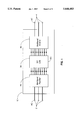
- FIG. 3 is a schematic diagram of a single phase leg of a five level converter having the DC link of the claimed invention.
- FIG. 4 is a schematic diagram showing the circuit elements associated with each of the respective rectifier and inverter switching components.
- FIG. 5 is a graph showing the phase voltage waveform for the inverter side of the single phase leg of the five level converter shown in FIG. 3.
- FIG. 6 is a schematic diagram illustrating a typical three phase back-to-back intertie of two high power AC system grids using the claimed invention.
- FIG. 7 is a graph showing the simulated results of capacitor voltage values for all four voltage levels of the multilevel converter shown in FIG. 6.
- FIG. 8 is a graph showing the synthesized one cycle steady-state multilevel output line-to-line voltage for the multilevel converter shown in FIG. 6.
- FIG. 9 is a graph showing the simulation results of the steady-state line current and the respective source phase voltage under non-unity power factor operation for the multilevel converter shown in FIG. 6.
- FIG. 10 is a graph showing the simulation results of the steady-state line current and the respective source phase voltage under unity power factor operation for the multilevel converter shown in FIG. 6.
- FIG. 11a is a voltage response graph showing the experimental results of the output line voltage produced by a 6-level inverter.
- FIG. 11b is a current response graph showing the experimental results of the output line current produced by a 6-level inverter.
- FIG. 12a is a line voltage graph showing the 6-level converter experimental input voltage waveforms used to obtain the output line voltage and current waveforms shown in FIGS. 11a and 11b.
- FIG. 12b is a line current graph showing the 6-level converter experimental input current waveform used to obtain the output line voltage and current waveforms shown in FIGS. 11 a and 11b.
- FIG. 13 is shows a full bridge embodiment of the present invention enabling back-to-back intertie of a single-phase source and a three-phase load.
- FIG. 1 a functional block diagram showing the preferred embodiment of the apparatus of the present invention.
- the preferred embodiment of the invention utilizes a rectifier 20, an inverter 40 and a DC link 30 to accomplish the objects of the instant invention.
- FIG. 2 generally shows the multilevel converter 10 having the DC link 30 between each corresponding voltage level of the rectifier 20 and inverter 40, respectively.
- the multilevel converter 10 can have an unlimited number of levels. The number of capacitors required for either the rectifier 20 or the inverter 40 is determined by:
- m c is the number of capacitors used with the rectifier and inverter, respectively, and m is the number of converter voltage levels.
- the number of switching devices needed for each phase leg is determined by:
- m s is the number of switching devices needed for each phase leg of the rectifier and inverter, respectively, and m is the number of converter voltage levels.
- each half of each phase of the rectifier 20 and inverter 40 of the multilevel converter 10 respectively consists of m-1 switches, where m is the number of converter voltage levels.
- the capacitor voltage present at the rectifier output nodes 25 and the inverter input nodes 45 will be highly unbalanced if said nodes are not connected with respect to similar voltage levels between the rectifier 20 and the inverter 40.
- the respective DC link capacitors 32 and 34 tend to compensate for one another thereby providing voltage balancing at the DC link 30 in the multilevel converter 10.
- the rectifier 20 as shown in FIG. 3 has eight switches 50, 51, 52, 53, 54, 55, 56 and 57.
- Each switch comprises a gate controlled device 58 and an anti-parallel diode 59 as shown in FIG. 4.
- the gate controlled device 58 and the anti-parallel diode 59 may be either a single module or a set of modules connected in series.
- the gate turn-off devices may be any of the components capable of switching such as a gate turn-off thyristor, an insulated gate bipolar transistor, a power MOSFET, a MOSFET controlled thyristor, a bipolar junction transistor, a static induction transistor, a static induction thyristor or a MOSFET controlled thyristor.
- the AC phase input node 2 connects to the middle node 21 of the rectifier 20.
- the AC phase node 4 connects to the middle node 49 of the inverter 40. Due to the symmetrical connection and configuration of the converter 10, the roles of the rectifier 20 and inverter 40 can be swapped when the direction of power flow is reversed.
- the DC link 30 comprises four capacitors connected in series.
- the rectifier capacitors are represented by 61, 62, 63 and 64 while the inverter capacitors are represented by 71, 72, 73 and 74.
- the connections between the capacitors and the corresponding switches are blocked by diodes 22, 23, 26, 27, 28 and 29 on the rectifier side and by diodes 41, 42, 43, 46, 47 and 48 on the inverter side.
- diode 22 is required to prevent capacitor 61 through switch 50.
- Diode 23 is required to prevent capacitors 62, 63 and 64 through switches 55, 56 and 57.
- a similar configuration of blocking diodes is required on the inverter side of the multilevel converter.
- the inner two switches, 51 and 56 are conductive for a longer period than the outer two switches, 50 and 57, and the inner two capacitors, 62 and 63, are charged more than the outer two capacitors, 61 and 64.
- the inner two switches, 81 and 86 are conductive for a longer period than the outer two switches, 80 and 87, and the inner two capacitors, 72 and 73, are discharged more than the outer two capacitors, 71 and 74.
- the converter AC phase output wave 3 at the inverter output node 4 of the circuit shown in FIG. 3, is shown having five voltage levels: -0.25 V s , -0.5 V s 0.25 V s and 0.5 V s , where V s is the DC link voltage.
- Switches 81, 82, 83 and 84 must be conducting to obtain 0.25 V s at node 4.
- the following table details the relationships between the different levels of output phase voltages with respect to switch states.
- the middle two switches, 81 and 86 which are required for the 0.25 V s and 0.5 V s levels, must be conducting for a longer period than the outer two switches, 80 and 87 which are only required for the 0.5 V s level.
- the middle two capacitors, 72 and 73 will be discharged more than the outer capacitors, 71 and 74.
- the middle two capacitors, 62 and 63 will be charged more than the outer two capacitors, 61 and 64.
- the voltage unbalance occurs at the DC link 30 between the rectifier 20 and the inverter 40 but in opposite directions.
- the three phase source 90 having sinusoidal phase voltages of V sa , V sb , and V sc is tied to the load 95 having phase voltages of V la , V lb and V lc .
- the AC intertie can produce large circulating currents and losses due to unsynchronization.
- the multilevel converter connects a multilevel rectifier 20 to the source 90 and a multilevel inverter to the load 95 with the DC link 30 as previously described.
- System simulation results as shown in FIG. 7 show that all four DC Link capacitor voltages are identical at the steady state.
- FIG. 10 shows that under non-unity power factor operation, steady-state line current 7 leads the phase voltage 6. As shown in FIG. 10, with unity power factor operation, the line current 7 more closely tracks the corresponding phase voltage 6 with less distortion in the line current waveform. This plot demonstrates that the line current 7 and phase voltage 6 are in phase with respect to each other thereby eliminating the need for reactive power compensation. Drawing reactive power is the one of the most significant disadvantages of conventional DC intertie systems. It will be obvious to those of ordinary skill in the relevant art that FIG. 10 also demonstrates that power factor and harmonic distortion can be controlled through proper control system design. By increasing the number of voltage levels, the current harmonics and the size of the harmonic filters can be further reduced.
- FIG. 12a shows the source line-to-line voltage 8 and the converter line-to-line voltage 9 of the aforementioned six-level multilevel converter.
- FIG. 12b shows the corresponding input current waveform 13.
- the multilevel converter may be applied to high voltage AC power systems having different phase quantities.
- the source may be a single-phase power system 120 while the load is a three-phase power system 118.
- the DC link 30 and inverter 40 are configured in the manner previously described herein. It will be obvious to one of ordinary skill in the art that similar configurations of the multilevel converter will allow a variety of dissimilar phase numbered system interties.
- This multilevel converter system may be applied to a variety of high voltage AC power applications.
- One such application is for the back-to-back intertie of high voltage AC power systems having dissimilar phase frequencies or other system dynamics.
- the multilevel converter may also be used for phase shift intertie between two high voltage AC power systems having dissimilar power phase angles. Yet another application would be to provide reactive power compensation between two high voltage AC power systems.
- This multilevel converter may also be applied to adjustable speed motor drive systems.
- Conventional motor drives normally use either current source inverters or voltage source inverters having square wave or pulse-width modulation. Problems typically encountered with conventional motor drives utilizing these rectifier/inverter methods include non-unity power factor at the rectifier input and non-sinusoidal voltage or current at the inverter output. Applying the multilevel converter described herein, utilizing the adjustable speed drive motor as either the source or the load, near sinusoidal voltage and current at the rectifier input and the inverter output may be obtained. Unity power factor may also be obtained.
Abstract
Description
m.sub.c =m-1 Eq. 1
m.sub.s =2(m-1) Eq. 2
              TABLE 1
______________________________________
Conductive States for Inverter Switches 80, 81, 82, 83, 84, 85,
86 and 87 for voltage waveform shown in FIG. 5
       SWITCH STATE
OUTPUT   80    81      82  83    84  85    86  87
______________________________________
0.5V.sub.s
         1     1       1   1     0   0     0   0
0.25V.sub.s
         0     1       1   1     1   0     0   0
0        0     0       1   1     1   1     0   0
-0.25V.sub.s
         0     0       0   1     1   1     1   0
-0.5V.sub.s
         0     0       0   0     1   1     1   1
______________________________________
Claims (10)
Priority Applications (1)
| Application Number | Priority Date | Filing Date | Title |
|---|---|---|---|
| US08/446,366 US5644483A (en) | 1995-05-22 | 1995-05-22 | Voltage balanced multilevel voltage source converter system |
Applications Claiming Priority (1)
| Application Number | Priority Date | Filing Date | Title |
|---|---|---|---|
| US08/446,366 US5644483A (en) | 1995-05-22 | 1995-05-22 | Voltage balanced multilevel voltage source converter system |
Publications (1)
| Publication Number | Publication Date |
|---|---|
| US5644483A true US5644483A (en) | 1997-07-01 |
Family
ID=23772320
Family Applications (1)
| Application Number | Title | Priority Date | Filing Date |
|---|---|---|---|
| US08/446,366 Expired - Fee Related US5644483A (en) | 1995-05-22 | 1995-05-22 | Voltage balanced multilevel voltage source converter system |
Country Status (1)
| Country | Link |
|---|---|
| US (1) | US5644483A (en) |
Cited By (71)
| Publication number | Priority date | Publication date | Assignee | Title |
|---|---|---|---|---|
| US5796598A (en) * | 1996-01-26 | 1998-08-18 | W. Schlafhorst Ag & Co. | Voltage-converting circuit for the power supply of an electrical consumer of high output, particularly a bobbin winding machine |
| EP0895341A2 (en) * | 1997-07-29 | 1999-02-03 | Gec Alsthom Limited | Switching control arrangement |
| WO1999041828A1 (en) * | 1998-02-13 | 1999-08-19 | Wisconsin Alumni Research Foundation | Hybrid topology for multilevel power conversion |
| US6031738A (en) * | 1998-06-16 | 2000-02-29 | Wisconsin Alumni Research Foundation | DC bus voltage balancing and control in multilevel inverters |
| US6075350A (en) * | 1998-04-24 | 2000-06-13 | Lockheed Martin Energy Research Corporation | Power line conditioner using cascade multilevel inverters for voltage regulation, reactive power correction, and harmonic filtering |
| US6118932A (en) * | 1998-03-23 | 2000-09-12 | Electric Boat Corporation | Method and arrangement for a high voltage single-stage variable speed drive |
| US6160722A (en) * | 1999-08-13 | 2000-12-12 | Powerware Corporation | Uninterruptible power supplies with dual-sourcing capability and methods of operation thereof |
| USRE37126E1 (en) * | 1995-09-14 | 2001-04-03 | Lockheed Martin Energy Systems, Inc. | Multilevel cascade voltage source inverter with seperate DC sources |
| US6225773B1 (en) * | 1998-01-02 | 2001-05-01 | Japan Servo Company Ltd. | Stepping motor and having external rotor and electromagnetic-combined-permanent magnet stator |
| US6307760B1 (en) * | 2000-02-25 | 2001-10-23 | Hitachi, Ltd. | Three level inverter apparatus |
| US6337802B1 (en) * | 1999-10-05 | 2002-01-08 | Abb Ab | Device for energizing a voltage-source converter |
| US6340851B1 (en) | 1998-03-23 | 2002-01-22 | Electric Boat Corporation | Modular transformer arrangement for use with multi-level power converter |
| US6459596B1 (en) | 2000-08-18 | 2002-10-01 | The United States Of America As Represented By The Secretary Of The Navy | Method and apparatus for a Reduced parts-counts multilevel rectifier |
| US6483730B2 (en) | 1999-08-13 | 2002-11-19 | Powerware Corporation | Power converters with AC and DC operating modes and methods of operation thereof |
| US20040218318A1 (en) * | 2001-04-11 | 2004-11-04 | Bo Bijlenga | Converter |
| US6819576B2 (en) | 1999-08-13 | 2004-11-16 | Powerware Corporation | Power conversion apparatus and methods using balancer circuits |
| US20040267468A1 (en) * | 2003-06-30 | 2004-12-30 | Baker Hughes Incorporated | Low harmonic diode clamped converter/inverter |
| US20050041443A1 (en) * | 2003-08-21 | 2005-02-24 | Siemens Aktiengesellschaft | Voltage source converter |
| US20050111245A1 (en) * | 2003-11-25 | 2005-05-26 | Jih-Sheng Lai | Multifunction hybrid intelligent universal transformer |
| US20050111246A1 (en) * | 2003-11-25 | 2005-05-26 | Jih-Sheng Lai | Multilevel converter based intelligent universal transformer |
| US20050270000A1 (en) * | 2004-03-31 | 2005-12-08 | Liuchen Chang | Single-stage buck-boost inverter |
| US20060245216A1 (en) * | 2005-04-15 | 2006-11-02 | Rockwell Automation, Inc. | DC voltage balance control for three-level NPC power converters with even-order harmonic elimination scheme |
| US20060274561A1 (en) * | 2003-05-16 | 2006-12-07 | Ballard Power Systems Corporation | Tri-level inverter |
| US20070223258A1 (en) * | 2003-11-25 | 2007-09-27 | Jih-Sheng Lai | Multilevel converters for intelligent high-voltage transformers |
| US20070230226A1 (en) * | 2003-11-25 | 2007-10-04 | Jih-Sheng Lai | Multilevel intelligent universal auto-transformer |
| US20080218320A1 (en) * | 2007-03-05 | 2008-09-11 | Ls Industrial Systems Co., Ltd | Multilevel inverter using cascade configuration and control method thereof |
| US20080259663A1 (en) * | 2007-04-23 | 2008-10-23 | Perkinson Joseph C | Methods and apparatus for three-phase rectifier with lower voltage switches |
| US20080291708A1 (en) * | 2007-05-25 | 2008-11-27 | General Electric Company | Protective circuit and method for multi-level converter |
| US20100156354A1 (en) * | 2007-02-21 | 2010-06-24 | American Power Conversion Corporation | 3-phase high power ups |
| WO2010078999A1 (en) * | 2008-12-18 | 2010-07-15 | Abb Research Ltd | Converter device and method for controlling a converter device |
| CN101834451A (en) * | 2010-05-07 | 2010-09-15 | 中国科学院电工研究所 | High-voltage back-to-back converter |
| CN101834452A (en) * | 2010-05-07 | 2010-09-15 | 中国科学院电工研究所 | Back-to-back converter for high-voltage alternating current drive |
| US20100259955A1 (en) * | 2007-12-11 | 2010-10-14 | Tokyo Institute Of Technology | Soft switching power converter |
| WO2011008514A2 (en) * | 2009-06-30 | 2011-01-20 | Teco-Westinghouse Motor Company | Pluggable power cell for an inverter and providing modular power conversion |
| US20110044010A1 (en) * | 2009-06-30 | 2011-02-24 | Enrique Ledezma | Pluggable power cell for an inverter |
| US20110044077A1 (en) * | 2009-08-20 | 2011-02-24 | Henning Roar Nielsen | 3-phase high-power ups |
| US20110103116A1 (en) * | 2008-06-12 | 2011-05-05 | Abb Technology Ag | Plant for transmitting electric power |
| US20110110136A1 (en) * | 2009-11-06 | 2011-05-12 | Mge Ups | Converter device comprising at least five DC voltage levels and uninterruptible power supply provided with said device |
| US20110215890A1 (en) * | 2009-06-30 | 2011-09-08 | Mehdi Abolhassani | Providing A Transformer For An Inverter |
| US20110273917A1 (en) * | 2010-05-05 | 2011-11-10 | Electric Power Research Institute, Inc. | Intelligent photovoltaic interface and system |
| CN101345423B (en) * | 2008-05-07 | 2011-11-16 | 中国科学院电工研究所 | 5-power level H-bridge cascade connection back-to-back current transformer used for wind power generation system |
| US20110291737A1 (en) * | 2010-05-26 | 2011-12-01 | Hamilton Sundstrand Corporation | Multilevel Unidirectional Rectifier with N-2 Switches Per Phase Leg |
| US8130501B2 (en) | 2009-06-30 | 2012-03-06 | Teco-Westinghouse Motor Company | Pluggable power cell for an inverter |
| US20120112545A1 (en) * | 2010-11-04 | 2012-05-10 | Curtiss-Wright Electro-Mechanical Corporation | M2LC System Coupled to a Rectifier System |
| WO2012087869A2 (en) * | 2010-12-22 | 2012-06-28 | Converteam Technology Ltd. | Mechanical arrangement of a multilevel power converter circuit |
| US8254076B2 (en) | 2009-06-30 | 2012-08-28 | Teco-Westinghouse Motor Company | Providing modular power conversion |
| US20130016537A1 (en) * | 2011-07-14 | 2013-01-17 | Heng Deng | Method for controlling a frequency converter and frequency converter |
| WO2013017353A1 (en) * | 2011-08-04 | 2013-02-07 | Abb Technology Ag | Transformerless multilevel converter |
| US20130063070A1 (en) * | 2011-09-13 | 2013-03-14 | Delta Electronics (Shanghai) Co., Ltd. | Medium voltage variable frequency driving system |
| CN103236797A (en) * | 2013-04-17 | 2013-08-07 | 西安交通大学 | Method for controlling balance of capacitive voltages of five-level diode neutral point clamped converter |
| US20130200619A1 (en) * | 2010-04-29 | 2013-08-08 | Ingeteam Power Technology, S.A. | Electric generator control system and method |
| US20130208519A1 (en) * | 2012-02-09 | 2013-08-15 | Hitachi, Ltd. | Switching Element, Power Converter, Direct Current Transmission System, Current Control Device, Method of Controlling Power Converter, and Method of Controlling Current in Voltage Source Converter |
| WO2014046555A1 (en) * | 2012-09-21 | 2014-03-27 | Auckland Uniservices Limited | Improvements in or relating to modular multi-level converters |
| US20140092661A1 (en) * | 2012-09-28 | 2014-04-03 | General Electric Company | Multilevel converter system |
| US20140241019A1 (en) * | 2013-02-27 | 2014-08-28 | Varentec, Inc. | Multi-level rectifiers |
| EP2706653A4 (en) * | 2012-06-30 | 2015-06-10 | Huawei Tech Co Ltd | Five-level power converter, controlling method and controlling device thereof |
| US20150229234A1 (en) * | 2014-02-11 | 2015-08-13 | Korea Electrotechnology Research Institute | Driving apparatus and method for modular multi-level converter |
| US20160028321A1 (en) * | 2014-07-28 | 2016-01-28 | Hamilton Sundstrand Corporation | Power converters for aircraft starter/generators |
| CN105391322A (en) * | 2014-08-22 | 2016-03-09 | 通用电气公司 | Multilevel converter |
| US20160069327A1 (en) * | 2014-09-05 | 2016-03-10 | Delta Electronics, Inc. | Wind power converter device and converter device |
| US9312705B2 (en) | 2010-12-22 | 2016-04-12 | Ge Energy Power Conversion Technology Limited | Capacitor balancing circuit and control method for an electronic device such as a multilevel power inverter |
| US9318974B2 (en) | 2014-03-26 | 2016-04-19 | Solaredge Technologies Ltd. | Multi-level inverter with flying capacitor topology |
| US9431918B2 (en) | 2012-09-28 | 2016-08-30 | General Electric Company | Grounding scheme for modular embedded multilevel converter |
| US9444320B1 (en) | 2012-04-16 | 2016-09-13 | Performance Controls, Inc. | Power controller having active voltage balancing of a power supply |
| US9843270B2 (en) | 2015-01-13 | 2017-12-12 | Hamilton Sundstrand Corporation | Phase leg arrangements for multilevel active rectifiers |
| US9941813B2 (en) | 2013-03-14 | 2018-04-10 | Solaredge Technologies Ltd. | High frequency multi-level inverter |
| US10439414B2 (en) | 2017-03-23 | 2019-10-08 | Eaton Intelligent Power Limited | Auto adjusting balancer apparatus |
| JP2021027646A (en) * | 2019-08-01 | 2021-02-22 | 東芝三菱電機産業システム株式会社 | Controller and power conversion system |
| US20210376753A1 (en) * | 2020-05-26 | 2021-12-02 | Delta Electronics (Shanghai) Co., Ltd | Conversion device |
| US20210376739A1 (en) * | 2020-05-26 | 2021-12-02 | Delta Electronics (Shanghai) Co., Ltd | Conversion device |
| USRE49768E1 (en) * | 2014-09-05 | 2023-12-26 | Delta Electronics, Inc. | Wind power converter device and converter device |
Citations (3)
| Publication number | Priority date | Publication date | Assignee | Title |
|---|---|---|---|---|
| US4651266A (en) * | 1984-02-16 | 1987-03-17 | Fanuc Ltd | High-frequency noise absorbing circuit |
| US5038267A (en) * | 1990-05-03 | 1991-08-06 | General Electric Company | Soft-switching power converter for operation in discrete pulse modulation and pulse width modulation modes |
| US5172309A (en) * | 1991-08-07 | 1992-12-15 | General Electric Company | Auxiliary quasi-resonant dc link converter |
-
1995
- 1995-05-22 US US08/446,366 patent/US5644483A/en not_active Expired - Fee Related
Patent Citations (3)
| Publication number | Priority date | Publication date | Assignee | Title |
|---|---|---|---|---|
| US4651266A (en) * | 1984-02-16 | 1987-03-17 | Fanuc Ltd | High-frequency noise absorbing circuit |
| US5038267A (en) * | 1990-05-03 | 1991-08-06 | General Electric Company | Soft-switching power converter for operation in discrete pulse modulation and pulse width modulation modes |
| US5172309A (en) * | 1991-08-07 | 1992-12-15 | General Electric Company | Auxiliary quasi-resonant dc link converter |
Non-Patent Citations (2)
| Title |
|---|
| D.A. Woodford, et. al., "Controlling a Back-to-Back DC Link to Operate as a Phase Shift Transformer", CIGRE 1994 Session Papers, Group 14, Paper 14-202, 1994 France. |
| D.A. Woodford, et. al., Controlling a Back to Back DC Link to Operate as a Phase Shift Transformer , CIGRE 1994 Session Papers, Group 14, Paper 14 202, 1994 France. * |
Cited By (139)
| Publication number | Priority date | Publication date | Assignee | Title |
|---|---|---|---|---|
| USRE37126E1 (en) * | 1995-09-14 | 2001-04-03 | Lockheed Martin Energy Systems, Inc. | Multilevel cascade voltage source inverter with seperate DC sources |
| US5796598A (en) * | 1996-01-26 | 1998-08-18 | W. Schlafhorst Ag & Co. | Voltage-converting circuit for the power supply of an electrical consumer of high output, particularly a bobbin winding machine |
| EP0895341A2 (en) * | 1997-07-29 | 1999-02-03 | Gec Alsthom Limited | Switching control arrangement |
| EP0895341A3 (en) * | 1997-07-29 | 2000-11-15 | Gec Alsthom Limited | Switching control arrangement |
| US6225773B1 (en) * | 1998-01-02 | 2001-05-01 | Japan Servo Company Ltd. | Stepping motor and having external rotor and electromagnetic-combined-permanent magnet stator |
| WO1999041828A1 (en) * | 1998-02-13 | 1999-08-19 | Wisconsin Alumni Research Foundation | Hybrid topology for multilevel power conversion |
| US6340851B1 (en) | 1998-03-23 | 2002-01-22 | Electric Boat Corporation | Modular transformer arrangement for use with multi-level power converter |
| US6118932A (en) * | 1998-03-23 | 2000-09-12 | Electric Boat Corporation | Method and arrangement for a high voltage single-stage variable speed drive |
| US6075350A (en) * | 1998-04-24 | 2000-06-13 | Lockheed Martin Energy Research Corporation | Power line conditioner using cascade multilevel inverters for voltage regulation, reactive power correction, and harmonic filtering |
| US6031738A (en) * | 1998-06-16 | 2000-02-29 | Wisconsin Alumni Research Foundation | DC bus voltage balancing and control in multilevel inverters |
| US6483730B2 (en) | 1999-08-13 | 2002-11-19 | Powerware Corporation | Power converters with AC and DC operating modes and methods of operation thereof |
| US6314007B2 (en) | 1999-08-13 | 2001-11-06 | Powerware Corporation | Multi-mode power converters incorporating balancer circuits and methods of operation thereof |
| US6819576B2 (en) | 1999-08-13 | 2004-11-16 | Powerware Corporation | Power conversion apparatus and methods using balancer circuits |
| US6160722A (en) * | 1999-08-13 | 2000-12-12 | Powerware Corporation | Uninterruptible power supplies with dual-sourcing capability and methods of operation thereof |
| US6337802B1 (en) * | 1999-10-05 | 2002-01-08 | Abb Ab | Device for energizing a voltage-source converter |
| US6307760B1 (en) * | 2000-02-25 | 2001-10-23 | Hitachi, Ltd. | Three level inverter apparatus |
| US6459596B1 (en) | 2000-08-18 | 2002-10-01 | The United States Of America As Represented By The Secretary Of The Navy | Method and apparatus for a Reduced parts-counts multilevel rectifier |
| US6898095B2 (en) * | 2001-04-11 | 2005-05-24 | Abb Ab | Bidirectional VSC converter with a resonant circuit |
| US20040218318A1 (en) * | 2001-04-11 | 2004-11-04 | Bo Bijlenga | Converter |
| US7505294B2 (en) * | 2003-05-16 | 2009-03-17 | Continental Automotive Systems Us, Inc. | Tri-level inverter |
| US20060274561A1 (en) * | 2003-05-16 | 2006-12-07 | Ballard Power Systems Corporation | Tri-level inverter |
| US20040267468A1 (en) * | 2003-06-30 | 2004-12-30 | Baker Hughes Incorporated | Low harmonic diode clamped converter/inverter |
| US7040391B2 (en) | 2003-06-30 | 2006-05-09 | Baker Hughes Incorporated | Low harmonic diode clamped converter/inverter |
| EP1494344A1 (en) * | 2003-06-30 | 2005-01-05 | Baker Hughes Incorporated | Multilevel power converting apparatus |
| US7250794B2 (en) * | 2003-08-21 | 2007-07-31 | Siemens Aktiengesellschaft | Voltage source converter |
| US20050041443A1 (en) * | 2003-08-21 | 2005-02-24 | Siemens Aktiengesellschaft | Voltage source converter |
| US7050311B2 (en) | 2003-11-25 | 2006-05-23 | Electric Power Research Institute, Inc. | Multilevel converter based intelligent universal transformer |
| US20060028848A1 (en) * | 2003-11-25 | 2006-02-09 | Jih-Sheng Lai | Multifunction hybrid intelligent universal transformer |
| US20050111245A1 (en) * | 2003-11-25 | 2005-05-26 | Jih-Sheng Lai | Multifunction hybrid intelligent universal transformer |
| US6954366B2 (en) | 2003-11-25 | 2005-10-11 | Electric Power Research Institute | Multifunction hybrid intelligent universal transformer |
| US20070223258A1 (en) * | 2003-11-25 | 2007-09-27 | Jih-Sheng Lai | Multilevel converters for intelligent high-voltage transformers |
| US20070230226A1 (en) * | 2003-11-25 | 2007-10-04 | Jih-Sheng Lai | Multilevel intelligent universal auto-transformer |
| US20050111246A1 (en) * | 2003-11-25 | 2005-05-26 | Jih-Sheng Lai | Multilevel converter based intelligent universal transformer |
| US20050270000A1 (en) * | 2004-03-31 | 2005-12-08 | Liuchen Chang | Single-stage buck-boost inverter |
| US20060245216A1 (en) * | 2005-04-15 | 2006-11-02 | Rockwell Automation, Inc. | DC voltage balance control for three-level NPC power converters with even-order harmonic elimination scheme |
| US7495938B2 (en) * | 2005-04-15 | 2009-02-24 | Rockwell Automation Technologies, Inc. | DC voltage balance control for three-level NPC power converters with even-order harmonic elimination scheme |
| US8344551B2 (en) | 2007-02-21 | 2013-01-01 | American Power Conversion Corporation | 3-phase high-power UPS |
| KR101521137B1 (en) * | 2007-02-21 | 2015-05-20 | 슈나이더 일렉트릭 아이티 코포레이션 | 3-phase high-power ups |
| US8664796B2 (en) | 2007-02-21 | 2014-03-04 | Schneider Electric II Corporation | 3-phase high power ups |
| CN101657946B (en) * | 2007-02-21 | 2013-11-13 | 美国能量变换公司 | 3-phase high power ups |
| US20100156354A1 (en) * | 2007-02-21 | 2010-06-24 | American Power Conversion Corporation | 3-phase high power ups |
| EP2587620A3 (en) * | 2007-02-21 | 2013-07-03 | American Power Conversion Corporation | DC bus balancer circuit |
| EP2587620A2 (en) * | 2007-02-21 | 2013-05-01 | American Power Conversion Corporation | DC bus balancer circuit |
| US8008809B2 (en) | 2007-02-21 | 2011-08-30 | American Power Conversion Corporation | 3-phase high power UPS |
| US8018331B2 (en) * | 2007-03-05 | 2011-09-13 | Ls Industrial Systems Co., Ltd. | Multilevel inverter using cascade configuration and control method thereof |
| US20080218320A1 (en) * | 2007-03-05 | 2008-09-11 | Ls Industrial Systems Co., Ltd | Multilevel inverter using cascade configuration and control method thereof |
| US7751212B2 (en) * | 2007-04-23 | 2010-07-06 | Raytheon Company | Methods and apparatus for three-phase rectifier with lower voltage switches |
| US20080259663A1 (en) * | 2007-04-23 | 2008-10-23 | Perkinson Joseph C | Methods and apparatus for three-phase rectifier with lower voltage switches |
| US20080291708A1 (en) * | 2007-05-25 | 2008-11-27 | General Electric Company | Protective circuit and method for multi-level converter |
| US7573732B2 (en) * | 2007-05-25 | 2009-08-11 | General Electric Company | Protective circuit and method for multi-level converter |
| US20100259955A1 (en) * | 2007-12-11 | 2010-10-14 | Tokyo Institute Of Technology | Soft switching power converter |
| CN101345423B (en) * | 2008-05-07 | 2011-11-16 | 中国科学院电工研究所 | 5-power level H-bridge cascade connection back-to-back current transformer used for wind power generation system |
| US8665617B2 (en) * | 2008-06-12 | 2014-03-04 | Abb Technology Ag | Plant for transmitting electric power |
| US20110103116A1 (en) * | 2008-06-12 | 2011-05-05 | Abb Technology Ag | Plant for transmitting electric power |
| US8564990B2 (en) | 2008-12-18 | 2013-10-22 | Abb Research Ltd | Converter device and method for controlling a converter device |
| WO2010078999A1 (en) * | 2008-12-18 | 2010-07-15 | Abb Research Ltd | Converter device and method for controlling a converter device |
| US8130501B2 (en) | 2009-06-30 | 2012-03-06 | Teco-Westinghouse Motor Company | Pluggable power cell for an inverter |
| US9220179B2 (en) | 2009-06-30 | 2015-12-22 | Teco-Westinghouse Motor Company | Pluggable power cell for an inverter |
| US20110044010A1 (en) * | 2009-06-30 | 2011-02-24 | Enrique Ledezma | Pluggable power cell for an inverter |
| US20110215890A1 (en) * | 2009-06-30 | 2011-09-08 | Mehdi Abolhassani | Providing A Transformer For An Inverter |
| US8575479B2 (en) | 2009-06-30 | 2013-11-05 | TECO—Westinghouse Motor Company | Providing a transformer for an inverter |
| WO2011008514A3 (en) * | 2009-06-30 | 2011-04-07 | Teco-Westinghouse Motor Company | Pluggable power cell for an inverter and providing modular power conversion |
| WO2011008514A2 (en) * | 2009-06-30 | 2011-01-20 | Teco-Westinghouse Motor Company | Pluggable power cell for an inverter and providing modular power conversion |
| US8254076B2 (en) | 2009-06-30 | 2012-08-28 | Teco-Westinghouse Motor Company | Providing modular power conversion |
| US9609777B2 (en) | 2009-06-30 | 2017-03-28 | Teco-Westinghouse Motor Company | Pluggable power cell for an inverter |
| US8711530B2 (en) | 2009-06-30 | 2014-04-29 | Teco-Westinghouse Motor Company | Pluggable power cell for an inverter |
| CN102187561A (en) * | 2009-06-30 | 2011-09-14 | 特科-西屋发动机公司 | Pluggable power cell for an inverter and providing modular power conversion |
| CN102577068A (en) * | 2009-08-20 | 2012-07-11 | 美国能量变换公司 | 3-phase high power UPS |
| US8842452B2 (en) | 2009-08-20 | 2014-09-23 | Schneider Electric It Corporation | 3-phase high power UPS |
| US20110044077A1 (en) * | 2009-08-20 | 2011-02-24 | Henning Roar Nielsen | 3-phase high-power ups |
| US8385091B2 (en) | 2009-08-20 | 2013-02-26 | Electric IT Corporation | 3-phase high-power UPS |
| US20110110136A1 (en) * | 2009-11-06 | 2011-05-12 | Mge Ups | Converter device comprising at least five DC voltage levels and uninterruptible power supply provided with said device |
| US8488336B2 (en) * | 2009-11-06 | 2013-07-16 | Mge Ups | Converter device comprising at least five DC voltage levels and uninterruptible power supply provided with said device |
| US20130200619A1 (en) * | 2010-04-29 | 2013-08-08 | Ingeteam Power Technology, S.A. | Electric generator control system and method |
| US8786119B2 (en) * | 2010-04-29 | 2014-07-22 | Ingeteam Power Technology, S.A. | Electric generator control system and method |
| US20110273917A1 (en) * | 2010-05-05 | 2011-11-10 | Electric Power Research Institute, Inc. | Intelligent photovoltaic interface and system |
| CN101834451A (en) * | 2010-05-07 | 2010-09-15 | 中国科学院电工研究所 | High-voltage back-to-back converter |
| CN101834452A (en) * | 2010-05-07 | 2010-09-15 | 中国科学院电工研究所 | Back-to-back converter for high-voltage alternating current drive |
| US8547717B2 (en) * | 2010-05-26 | 2013-10-01 | Hamilton Sundstrand Corporation | Multilevel unidirectional rectifier with N-2 switches per phase leg |
| US20110291737A1 (en) * | 2010-05-26 | 2011-12-01 | Hamilton Sundstrand Corporation | Multilevel Unidirectional Rectifier with N-2 Switches Per Phase Leg |
| US20120112545A1 (en) * | 2010-11-04 | 2012-05-10 | Curtiss-Wright Electro-Mechanical Corporation | M2LC System Coupled to a Rectifier System |
| US9444361B2 (en) | 2010-12-22 | 2016-09-13 | GE Power Conversion Technology, Ltd. | Mechanical arrangement of a multilevel power converter circuit |
| CN103493351A (en) * | 2010-12-22 | 2014-01-01 | 通用电气能源能量变换技术有限公司 | Mechanical arrangement of a multilevel power converter circuit |
| CN103493351B (en) * | 2010-12-22 | 2017-10-24 | 通用电气能源能量变换技术有限公司 | The mechanical device of many level power converter circuits |
| US9312705B2 (en) | 2010-12-22 | 2016-04-12 | Ge Energy Power Conversion Technology Limited | Capacitor balancing circuit and control method for an electronic device such as a multilevel power inverter |
| EP2656496A4 (en) * | 2010-12-22 | 2018-01-24 | GE Energy Power Conversion Technology Limited | Mechanical arrangement of a multilevel power converter circuit |
| WO2012087869A2 (en) * | 2010-12-22 | 2012-06-28 | Converteam Technology Ltd. | Mechanical arrangement of a multilevel power converter circuit |
| WO2012087869A3 (en) * | 2010-12-22 | 2012-10-11 | Converteam Technology Ltd. | Mechanical arrangement of a multilevel power converter circuit |
| US20130016537A1 (en) * | 2011-07-14 | 2013-01-17 | Heng Deng | Method for controlling a frequency converter and frequency converter |
| WO2013017353A1 (en) * | 2011-08-04 | 2013-02-07 | Abb Technology Ag | Transformerless multilevel converter |
| US8811048B2 (en) * | 2011-09-13 | 2014-08-19 | Delta Electronics (Shanghai) Co., Ltd. | Medium voltage variable frequency driving system |
| CN103001573A (en) * | 2011-09-13 | 2013-03-27 | 台达电子企业管理(上海)有限公司 | Medium-voltage frequency-conversion driving system |
| US20130063070A1 (en) * | 2011-09-13 | 2013-03-14 | Delta Electronics (Shanghai) Co., Ltd. | Medium voltage variable frequency driving system |
| US9219426B2 (en) * | 2012-02-09 | 2015-12-22 | Hitachi, Ltd. | Switching element, power converter, direct current transmission system, current control device, method of controlling power converter, and method of controlling current in voltage source converter |
| US20130208519A1 (en) * | 2012-02-09 | 2013-08-15 | Hitachi, Ltd. | Switching Element, Power Converter, Direct Current Transmission System, Current Control Device, Method of Controlling Power Converter, and Method of Controlling Current in Voltage Source Converter |
| US9444320B1 (en) | 2012-04-16 | 2016-09-13 | Performance Controls, Inc. | Power controller having active voltage balancing of a power supply |
| EP2706653A4 (en) * | 2012-06-30 | 2015-06-10 | Huawei Tech Co Ltd | Five-level power converter, controlling method and controlling device thereof |
| WO2014046555A1 (en) * | 2012-09-21 | 2014-03-27 | Auckland Uniservices Limited | Improvements in or relating to modular multi-level converters |
| US9559611B2 (en) * | 2012-09-28 | 2017-01-31 | General Electric Company | Multilevel power converter system and method |
| US20140092661A1 (en) * | 2012-09-28 | 2014-04-03 | General Electric Company | Multilevel converter system |
| US9431918B2 (en) | 2012-09-28 | 2016-08-30 | General Electric Company | Grounding scheme for modular embedded multilevel converter |
| US9190929B2 (en) * | 2013-02-27 | 2015-11-17 | Varentec, Inc. | Multi-level rectifiers |
| US20140241019A1 (en) * | 2013-02-27 | 2014-08-28 | Varentec, Inc. | Multi-level rectifiers |
| US9941813B2 (en) | 2013-03-14 | 2018-04-10 | Solaredge Technologies Ltd. | High frequency multi-level inverter |
| US11545912B2 (en) | 2013-03-14 | 2023-01-03 | Solaredge Technologies Ltd. | High frequency multi-level inverter |
| US11742777B2 (en) | 2013-03-14 | 2023-08-29 | Solaredge Technologies Ltd. | High frequency multi-level inverter |
| CN103236797A (en) * | 2013-04-17 | 2013-08-07 | 西安交通大学 | Method for controlling balance of capacitive voltages of five-level diode neutral point clamped converter |
| CN103236797B (en) * | 2013-04-17 | 2015-07-01 | 西安交通大学 | Method for controlling balance of capacitive voltages of five-level diode neutral point clamped converter |
| US9350270B2 (en) * | 2014-02-11 | 2016-05-24 | Korea Electrotechnology Research Institute | Driving apparatus and method for modular multi-level converter |
| US20150229234A1 (en) * | 2014-02-11 | 2015-08-13 | Korea Electrotechnology Research Institute | Driving apparatus and method for modular multi-level converter |
| US10886831B2 (en) | 2014-03-26 | 2021-01-05 | Solaredge Technologies Ltd. | Multi-level inverter |
| US10886832B2 (en) | 2014-03-26 | 2021-01-05 | Solaredge Technologies Ltd. | Multi-level inverter |
| US11855552B2 (en) | 2014-03-26 | 2023-12-26 | Solaredge Technologies Ltd. | Multi-level inverter |
| US11632058B2 (en) | 2014-03-26 | 2023-04-18 | Solaredge Technologies Ltd. | Multi-level inverter |
| US11296590B2 (en) | 2014-03-26 | 2022-04-05 | Solaredge Technologies Ltd. | Multi-level inverter |
| US10700588B2 (en) | 2014-03-26 | 2020-06-30 | Solaredge Technologies Ltd. | Multi-level inverter |
| US9318974B2 (en) | 2014-03-26 | 2016-04-19 | Solaredge Technologies Ltd. | Multi-level inverter with flying capacitor topology |
| US10680506B2 (en) | 2014-03-26 | 2020-06-09 | Solaredge Technologies Ltd. | Multi-level inverter |
| US10153685B2 (en) | 2014-03-26 | 2018-12-11 | Solaredge Technologies Ltd. | Power ripple compensation |
| US10404154B2 (en) | 2014-03-26 | 2019-09-03 | Solaredge Technologies Ltd | Multi-level inverter with flying capacitor topology |
| US10680505B2 (en) | 2014-03-26 | 2020-06-09 | Solaredge Technologies Ltd. | Multi-level inverter |
| US9590521B2 (en) * | 2014-07-28 | 2017-03-07 | Hamilton Sundstrand Corporation | Power converters for aircraft starter/generators |
| US20160028321A1 (en) * | 2014-07-28 | 2016-01-28 | Hamilton Sundstrand Corporation | Power converters for aircraft starter/generators |
| US9537421B2 (en) * | 2014-08-22 | 2017-01-03 | General Electric Company | Multilevel converter |
| CN105391322B (en) * | 2014-08-22 | 2019-10-11 | 通用电气公司 | Multilevel converter |
| CN105391322A (en) * | 2014-08-22 | 2016-03-09 | 通用电气公司 | Multilevel converter |
| US9768706B2 (en) * | 2014-09-05 | 2017-09-19 | Delta Electronics, Inc. | Wind power converter device and converter device |
| US20160069327A1 (en) * | 2014-09-05 | 2016-03-10 | Delta Electronics, Inc. | Wind power converter device and converter device |
| US10027239B2 (en) * | 2014-09-05 | 2018-07-17 | Delta Electronics, Inc. | Wind power converter device and converter device |
| US20170366096A1 (en) * | 2014-09-05 | 2017-12-21 | Delta Electronics, Inc. | Wind power converter device and converter device |
| USRE49768E1 (en) * | 2014-09-05 | 2023-12-26 | Delta Electronics, Inc. | Wind power converter device and converter device |
| US9843270B2 (en) | 2015-01-13 | 2017-12-12 | Hamilton Sundstrand Corporation | Phase leg arrangements for multilevel active rectifiers |
| US10944280B2 (en) | 2017-03-23 | 2021-03-09 | Eaton Intelligent Power Limited | Auto adjusting balancer apparatus |
| US10439414B2 (en) | 2017-03-23 | 2019-10-08 | Eaton Intelligent Power Limited | Auto adjusting balancer apparatus |
| JP2021027646A (en) * | 2019-08-01 | 2021-02-22 | 東芝三菱電機産業システム株式会社 | Controller and power conversion system |
| US20210376753A1 (en) * | 2020-05-26 | 2021-12-02 | Delta Electronics (Shanghai) Co., Ltd | Conversion device |
| US11515806B2 (en) * | 2020-05-26 | 2022-11-29 | Delta Electronics (Shanghai) Co., Ltd | Conversion device having reduced common-mode current |
| US11509239B2 (en) * | 2020-05-26 | 2022-11-22 | Delta Electronics (Shanghai) Co., Ltd | Conversion device having reduced size and cost |
| US20210376739A1 (en) * | 2020-05-26 | 2021-12-02 | Delta Electronics (Shanghai) Co., Ltd | Conversion device |
Similar Documents
| Publication | Publication Date | Title |
|---|---|---|
| US5644483A (en) | Voltage balanced multilevel voltage source converter system | |
| Ferreira | The multilevel modular DC converter | |
| Lai et al. | Multilevel converters-a new breed of power converters | |
| Peng et al. | A multilevel voltage-source converter system with balanced DC voltages | |
| US6236580B1 (en) | Modular multi-level adjustable supply with series connected active inputs | |
| Soto et al. | A comparison of high-power converter topologies for the implementation of FACTS controllers | |
| US9484835B2 (en) | Modified voltage source converter structure | |
| Sun et al. | Beyond the MMC: Extended modular multilevel converter topologies and applications | |
| WO2012163841A1 (en) | A voltage source converter for a hvdc transmission system | |
| Mazuela et al. | DC-link voltage balancing strategy based on SVM and reactive power exchange for a 5L-MPC back-to-back converter for medium-voltage drives | |
| Hochgraf et al. | A transformer-less static synchronous compensator employing a multi-level inverter | |
| US20160141962A1 (en) | Converter | |
| Mishra et al. | Comparison of total harmonic distortion of modular multilevel converter and parallel hybrid modular multilevel converter | |
| CN107947599A (en) | Electronic power convertor | |
| Merlin et al. | Alternate arm converter operation of the modular multilevel converter | |
| Liu et al. | Multi-level voltage sourced conversion by voltage reinjection at six times the fundamental frequency | |
| Tayyab et al. | Submodule capacitor voltage balancing of modular multilevel converter | |
| Miet et al. | Transformerless STATCOM based on a five-level modular multilevel converter | |
| AU2009344065A1 (en) | An arrangement for exchanging power | |
| Marinus et al. | A bridgeless controlled rectifier for single split-phase systems | |
| Muneshima et al. | A multilevel AC-AC conversion system and control method using Y-connected H-bridge circuits and bidirectional switches | |
| Morawiec et al. | Power electronic transformer based on cascaded H-bridge converter | |
| Wang et al. | X-type five-level current source inverter | |
| Mondal et al. | Control of M2C direct converter for AC to AC conversion with wide frequency range | |
| Idehen et al. | The series bridge converter: A compact and economic VSC-HVDC converter |
Legal Events
| Date | Code | Title | Description |
|---|---|---|---|
| AS | Assignment |
Owner name: MARTIN MARIETTA ENERGY SYSTEMS, INC., TENNESSEE Free format text: ASSIGNMENT OF ASSIGNORS INTEREST;ASSIGNOR:LAI, JIH-SHENG;REEL/FRAME:007502/0340 Effective date: 19950522 |
|
| AS | Assignment |
Owner name: UNIVERSITY OF TENNESSEE RESEARCH CORPORATION, TENN Free format text: ASSIGNMENT OF ASSIGNORS INTEREST;ASSIGNOR:PENG, FANG ZHENG;REEL/FRAME:007710/0649 Effective date: 19950913 |
|
| FPAY | Fee payment |
Year of fee payment: 4 |
|
| FPAY | Fee payment |
Year of fee payment: 8 |
|
| REMI | Maintenance fee reminder mailed | ||
| LAPS | Lapse for failure to pay maintenance fees | ||
| STCH | Information on status: patent discontinuation |
Free format text: PATENT EXPIRED DUE TO NONPAYMENT OF MAINTENANCE FEES UNDER 37 CFR 1.362 |
|
| FP | Lapsed due to failure to pay maintenance fee |
Effective date: 20090701 |