US4723098A - Electronic ballast circuit for fluorescent lamps - Google Patents

Electronic ballast circuit for fluorescent lamps Download PDF

Info

Publication number
US4723098A
US4723098A US07/033,701 US3370187A US4723098A US 4723098 A US4723098 A US 4723098A US 3370187 A US3370187 A US 3370187A US 4723098 A US4723098 A US 4723098A
Authority
US
United States
Prior art keywords
circuit
frequency
circuit means
inverter
voltage
Prior art date
Legal status (The legal status is an assumption and is not a legal conclusion. Google has not performed a legal analysis and makes no representation as to the accuracy of the status listed.)
Expired - Lifetime
Application number
US07/033,701
Inventor
Calvin E. Grubbs
Current Assignee (The listed assignees may be inaccurate. Google has not performed a legal analysis and makes no representation or warranty as to the accuracy of the list.)
Philips North America LLC
Thomas Industries Inc
Original Assignee
Thomas Industries Inc
Priority date (The priority date is an assumption and is not a legal conclusion. Google has not performed a legal analysis and makes no representation as to the accuracy of the date listed.)
Filing date
Publication date
Priority claimed from US06/194,783 external-priority patent/US4477748A/en
Application filed by Thomas Industries Inc filed Critical Thomas Industries Inc
Priority to US07/033,701 priority Critical patent/US4723098A/en
Application granted granted Critical
Publication of US4723098A publication Critical patent/US4723098A/en
Assigned to NORTH AMERICAN PHILIPS CORPORATION reassignment NORTH AMERICAN PHILIPS CORPORATION ASSIGNMENT OF ASSIGNORS INTEREST. Assignors: THOM,AS INDUSTRIES, INC.
Anticipated expiration legal-status Critical
Expired - Lifetime legal-status Critical Current

Links

Images

Classifications

    • HELECTRICITY
    • H05ELECTRIC TECHNIQUES NOT OTHERWISE PROVIDED FOR
    • H05BELECTRIC HEATING; ELECTRIC LIGHT SOURCES NOT OTHERWISE PROVIDED FOR; CIRCUIT ARRANGEMENTS FOR ELECTRIC LIGHT SOURCES, IN GENERAL
    • H05B41/00Circuit arrangements or apparatus for igniting or operating discharge lamps
    • H05B41/14Circuit arrangements
    • H05B41/26Circuit arrangements in which the lamp is fed by power derived from dc by means of a converter, e.g. by high-voltage dc
    • H05B41/28Circuit arrangements in which the lamp is fed by power derived from dc by means of a converter, e.g. by high-voltage dc using static converters
    • H05B41/295Circuit arrangements in which the lamp is fed by power derived from dc by means of a converter, e.g. by high-voltage dc using static converters with semiconductor devices and specially adapted for lamps with preheating electrodes, e.g. for fluorescent lamps
    • H05B41/298Arrangements for protecting lamps or circuits against abnormal operating conditions
    • H05B41/2981Arrangements for protecting lamps or circuits against abnormal operating conditions for protecting the circuit against abnormal operating conditions
    • HELECTRICITY
    • H02GENERATION; CONVERSION OR DISTRIBUTION OF ELECTRIC POWER
    • H02HEMERGENCY PROTECTIVE CIRCUIT ARRANGEMENTS
    • H02H7/00Emergency protective circuit arrangements specially adapted for specific types of electric machines or apparatus or for sectionalised protection of cable or line systems, and effecting automatic switching in the event of an undesired change from normal working conditions
    • H02H7/10Emergency protective circuit arrangements specially adapted for specific types of electric machines or apparatus or for sectionalised protection of cable or line systems, and effecting automatic switching in the event of an undesired change from normal working conditions for converters; for rectifiers
    • H02H7/12Emergency protective circuit arrangements specially adapted for specific types of electric machines or apparatus or for sectionalised protection of cable or line systems, and effecting automatic switching in the event of an undesired change from normal working conditions for converters; for rectifiers for static converters or rectifiers
    • H02H7/122Emergency protective circuit arrangements specially adapted for specific types of electric machines or apparatus or for sectionalised protection of cable or line systems, and effecting automatic switching in the event of an undesired change from normal working conditions for converters; for rectifiers for static converters or rectifiers for inverters, i.e. dc/ac converters
    • H02H7/1227Emergency protective circuit arrangements specially adapted for specific types of electric machines or apparatus or for sectionalised protection of cable or line systems, and effecting automatic switching in the event of an undesired change from normal working conditions for converters; for rectifiers for static converters or rectifiers for inverters, i.e. dc/ac converters responsive to abnormalities in the output circuit, e.g. short circuit
    • HELECTRICITY
    • H05ELECTRIC TECHNIQUES NOT OTHERWISE PROVIDED FOR
    • H05BELECTRIC HEATING; ELECTRIC LIGHT SOURCES NOT OTHERWISE PROVIDED FOR; CIRCUIT ARRANGEMENTS FOR ELECTRIC LIGHT SOURCES, IN GENERAL
    • H05B41/00Circuit arrangements or apparatus for igniting or operating discharge lamps
    • H05B41/14Circuit arrangements
    • H05B41/36Controlling
    • H05B41/38Controlling the intensity of light
    • H05B41/39Controlling the intensity of light continuously
    • H05B41/392Controlling the intensity of light continuously using semiconductor devices, e.g. thyristor
    • YGENERAL TAGGING OF NEW TECHNOLOGICAL DEVELOPMENTS; GENERAL TAGGING OF CROSS-SECTIONAL TECHNOLOGIES SPANNING OVER SEVERAL SECTIONS OF THE IPC; TECHNICAL SUBJECTS COVERED BY FORMER USPC CROSS-REFERENCE ART COLLECTIONS [XRACs] AND DIGESTS
    • Y10TECHNICAL SUBJECTS COVERED BY FORMER USPC
    • Y10STECHNICAL SUBJECTS COVERED BY FORMER USPC CROSS-REFERENCE ART COLLECTIONS [XRACs] AND DIGESTS
    • Y10S315/00Electric lamp and discharge devices: systems
    • Y10S315/07Starting and control circuits for gas discharge lamp using transistors

Landscapes

  • Engineering & Computer Science (AREA)
  • Power Engineering (AREA)
  • Circuit Arrangements For Discharge Lamps (AREA)

Abstract

An electronic ballast circuit for fluorescent or other gaseous discharge lamps includes a resonant half-bridge inverter circuit. The source voltage to the inverter is a full-wave rectified line voltage together with a DC carry-over voltage for supplying power in the inter-cusp period of the recitified line voltage. A negative feedback circuit is responsive to lamp current to vary the inverter drive frequency and thereby regulate lamp current. The frequency response of the feedback loop is high enough and the gain-versus-frequency response of the inverter is such that lamp current and voltage are regulated to reduce the crest factor of lamp current to compensate for variation in the amplitude of the voltage across the semi-conductor switches.

Description

RELATED APPLICATION
This is a continuation of application Ser. No. 661,397, filed Oct. 16, 1984, now abandoned, which is a continuation-in-part of application of my coowned application entitled "Solid State Ballast", Ser. No. 194,783, filed Oct. 7, 1980, now U.S. Pat. No. 4,477,748, the subject matter of which is incorporated herein in its entirety.
FIELD OF THE INVENTION
The present invention relates to a ballast circuit for fluorescent or other gaseous discharge lamps. More particularly, it relates to an electronic ballast circuit for energizing fluorescent lamps at high frequency from a conventional 60 Hz power source.
BACKGROUND OF THE INVENTION
As used herein, the term "fluorescent" is intended to include other gaseous discharge lamps such as high-intensity discharge lamps. It is known that these lamps operate more efficiently at frequencies higher than 60 Hz. Typically, such frequencies may range from 15 KHz to as high as 100 KHz. In the prior art, there have been many suggestions of electronic ballast circuits capable of high frequency operation, and there have also been commercial attempts to provide such electronic ballasts.
It has recently been recognized that to obtain longer life on fluorescent lamps designed for high frequency operation, the lamp current should be regulated to a degree higher than some may have thought necessary in earlier ballast circuits. There is a problem in obtaining a highly regulated lamp current because, in a ballast intended for residential or commercial use, conventional 60 Hz line voltage is the only practical source of power. Even when full-wave rectified, so that a 60 Hz source in effect becomes a 120 Hz source, there is substantial variation in the amplitude of the source voltage fed to the power transformer which normally energizes the lamp load. If this variation in amplitude is reflected in applied lamp current, it is undesirable because it is believed any such variation will reduce effective lamp life.
A measure or factor sometimes used by lamp manufacturers to limit or define operating specifications of a ballast to ensure longer lamp life is the "crest factor" which is defined as the ration of the peak amplitude of the lamp current to the rms value of lamp current. Some lamp manufacturers require, at least for certain lamps, that the crest factor of a solid state ballast operating at high frequency be less than 1.6. Such crest factors have not been attainable by the circuit as disclosed in my above-identified application Ser. No. 194,783. One of the reasons that desirable values of crest factor are not obtainable by the circuit as disclosed in that application is that the voltage is permitted to go to zero volts between the cusps of the full wave rectified source voltage. (This period between the peaks or cusps of the rectified voltage, when the voltage goes to zero volts, or to carry-over voltage if any auxiliary supply is used, is referred to as the "inter-cusp" period.) Even if an auxiliary source of DC voltage is used to store energy (as in a capacitor, for example), crest factors of less than 1.6 are nevertheless difficult to attain in such a system without auxiliary filters or unduly large values of components, which results in larger sizes of components, and that defeats some of the primary purposes of a solid state ballast--namely, reduction in the size of components and increased operating efficiency.
In some electronic ballasts, the crest factor is improved simply by adding large filters to the full wave rectified source voltage, but, in turn, adding bulky and costly components and reducing the overall efficiency of the ballast.
Thus, a principal object of the present invention is to provide an electronic ballast circuit for fluorescent lamps which regulates lamp current such that the crest factor of lamp current achieves a value of less than 1.6. It is further object of the present invention to do so without adding bulky and expensive filter components for filtering the source voltage.
SUMMARY OF THE INVENTION
The present invention includes a half-bridge inverter circuit designed to resonate at a predetermined high frequency. A negative feedback circuit senses lamp current and varies the excitation frequency of the lamp circuit to regulate lamp current. In particular, the frequency response of the feedback circuit is sufficiently high so that it is capable of responding to amplitude changes in the source voltage. In this manner, the lamp current may be regulated to a high degree, sufficient to reduce the crest factor of lamp current to values less than 1.6, if desired.
In the illustrated embodiment, the lamp current is sensed and a signal is generated representative of lamp current. The feedback loop contains a variable frequency oscillator which generates the gating signal for the semi-conductor switches of the inverter and thereby determines the operating frequency of the inverter. The inverter circuit itself, sometimes referred to herein as te "resonant amplifier" is therefore driven at a predetermined, controlled frequency which preferably is in a range of frequencies slightly above the actual resonant frequency of the inverter. Sensed lamp current controls the inverter frequency such that as lamp current is sensed to increase, the operating frequency is increased, thereby resulting in a reduced gain of the resonant amplifier, and a reduced voltage applied to the lamp circuit. That is, as the inverter driving frequency is increased, the response or "gain" of the inverter decreases. In this manner, lamp current can be regulated to achieve the desirable crest factors indicated above.
Other features and advantages of the present invention will be apparent to persons skilled in the art from the following detailed description of a preferred embodiment accompanied by the drawing.
BRIEF DESCRIPTION OF THE DRAWING
FIG. 1 is a functional block diagram of an electronic ballast circuit using negative feedback to regulate lamp current;
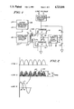
FIG. 2 shows idealized wave forms of signals illustrating the operation of the circuitry of FIG. 1;
FIG. 3 is a circuit schematic diagram, partly in functional block form, of an electronic ballast for gaseous discharge lamps constructed according to the present invention;
FIG. 4 is schematic diagram, partly in functional block form, of the timing and frequency control circuitry of FIG. 3;
FIG. 5 is a plot of gain versus frequency of the inverter circuit of FIG. 3; and
FIG. 6 contains graphs of idealized wave forms illustrating the performance of the operation of the circuitry of FIG. 3.
DETAILED DESCRIPTION OF PREFERRED EMBODIMENTS
Since the subject matter of co-pending application Ser. No. 194,783 has been expressly incorporated herein by reference, and because the preferred embodiment of the invention employs a different circuit configuration and technique in the feedback loop configuration, it is not necessary to repeat all the circuit detail of said application Ser. No. 194,783. However, in order to provide a foundation for a better understanding of the improvements rendered by the preferred embodiment, a brief description will be given of the circuitry of said co-pending application which regulates lamp current. Many other features and functions are disclosed in the referenced copending application, but do not form a part of the instant invention which is independent of those features, and they need not be repeated here.
Turning then to FIG. 1, reference numeral 10 generally designates a thyristor/capacitor bridge circuit including first and second thyristors (silicon control rectifiers) 11, 12 connected in series with a full-wave rectifier circuit 13 which receives standard 60 Hz line power and converts it to a full-wave rectifier circuit 13 which receives standard 60 Hz line power and converts it to a full-wave rectified output signal of 120 Hz, such as is illustrated in idealized form on line 1 of FIG. 2.
The bridge circuit 10 also includes first and second balanced capacitors 16, 17 connected in series to form two legs of the bridge. The diagonal branch of the bridge includes a power transformer generally designed 20, the output of which is coupled to a lamp load circuit comprising gaseous discharge lamps, such as fluorescent lamps, diagrammatically represented by the block 21.
The value of capacitors 16 and 17, and the inductance (including any reflected impedance from the load) of transformer 20 form a resonant circuit when thyristors 11, 12 are conducting.
The thyristors 11, 12 are gated "on" by a signal coupled through a pulse transformer generally designed 23. The transformer 23 includes a primary winding 24 driven by the Timing and Feedback Control Circuit 27, and first and second secondary windings 25, 26 which are connected in circuit respectively with the gate leads of thyristors 11, 12 in such a manner that current flowing through primary winding 24 of transformer 23 in one polarity will cause thyristor 11 to conduct, and current flowing through the primary winding 24 in the opposite polarity will cause thyristor 12 to conduct.
Timing for the Timing and Feedback Control Circuit 27 is derived from a Zero Cross-Over Detector Circuit 28 which receives a signal from a secondary winding in the power transformer 20. That signal is designated X-X, and the Zero Cross-Over Detector Circuit 28 generates a pulse each time the load current reverses polarity.
A signal designated R is generated in the lamp circuit representative of lamp current. The signal R is a level signal (not a sinusoidal signal) having a magnitude representative of a value of lamp current averaged over a number of cycles of the high frequency lamp current.
As explained above, when thyristor 11 conducts, capacitor 16 discharges at least partly, and a current represented by arrows I1 flows through thyristor 11 and the primary of transformer 20 from the positive to the negative terminal, and thence through capacitor 17 to ground. Because the transformer 20 and capacitors 16 and 17 form a resonant circuit, the current I1 will reverse in polarity dependent upon the resonant frequency of the circuit, and thereafter thyristor 12 will be gated to conduction with current flowing in the direction of the arrows I1. Thyristor 11 will be non-conducting at this time.
Thus, a high-frequency current oscillating at a frequency (which may be, for example, in the range of 20 KHz to 50 KHz) is generated in the lamp circuit and coupled to energize the lamp load. The positive half of the symmetrical resulting wave form at the output of the power transformer 20, again in idealized form, is seen on line 2 of FIG. 2. The envelope of the wave form is shown in phantom as a series of cusps and designated 30. It corresponds to the frequency and same general shape as the 120 Hz rectified line voltage of line 1. The lamp current goes to zero as the source voltage goes to zero during the inter-cusp period. A storage capacitor may be used to supply a carry over voltage in the inter-cusp period, in which case the envelope may be as seen at 33 on line 2. In either case, since the lamp current will have a generally similar envelope, the crest factor for lamp current is undesirably high.
To further explain the operation of the current regulating feature of the circuit of FIG. 1, an individual cycle of lamp current is shown, once more in idealized form, on an expanded time scale of line 3 of FIG. 2. It is sinusoidal in form, though, as mentioned above, the peak-to-peak value of that wave will depend upon the magnitude of the rectified source voltage.
Referring then to FIG. 1, the Zero Cross-Over Detector Circuit 28 generates a signal at a time represented in FIG. 2 by reference numeral 34 when current I1 or I2 goes through a zero value. The timing portion of the control circuit 27 thereupon establishes a fixed time delay represented diagrammatically by the arrow tD in line 3. If the lamp current, represented by the value of the signal R is a value which corresponds to a predetermined or reference value of current reflecting a desired lamp current, then the thyristor which is to be fired will be triggered at the end of the time tD. If the value of the signal R is greater than the predetermined reference value, indicating that lamp current is greater than desired, the feedback control circuit 27 delays the timing pulse proportionately so that, for example, the thyristor to be gated will not be gated on until a time t1. This will reduce the energy coupled to the resonant circuit and thus it will reduce the voltage applied to the power transformer 20. If, on the other hand, the magnitude of the signal R is less than the reference signal, it indicates that lamp current is less than the predetermined value, and the triggering of the thyristors will be advanced such as is illustrated at t2 in line 3, causing more energy to be coupled to the power transformer 20 since the thyristors will be energized earlier in the cycle of inverter current.
In this manner, lamp current is regulated as explained in my co-pending application. However, the response time of the feedback control circuit for the system of FIG. 2 is relatively slow--that is, of the order of a few tenths of a second. In other words, the -3 db point of the frequency response characteristic of the feedback circuit is of the order of 2-5 cy/sec. As a result, the amplitude of voltage applied to thelamp circuit and the amplitude of lamp current vary in accordance with the envelope of the voltage wave form seen on line 2. The resulting crest factor for lamp current is, as explained above, undesirable from the standpoint of criteria established by lamp manufacturers for longevity of lamps. Specifically, if the envelope of the signal of line 2 with the intercusp voltage going to zero represents peak lamp current and the arrow designated IRMS designates rms lamp current; and the crest factor has a value nominally in the range of 2.0-3.0.
Turning now to FIG. 3, there is shown a preferred circuit for achieving a regulated lamp current with reduced amplitude modulation of the voltage applied to the lamps and an improved crest factor for a lamp current. To facilitate comparison with the circuitry of FIG. 1, components in the circuit of FIG. 3 which have a similar function to those identified in FIG. 1 will be identified with a corresponding reference numeral preceded by a "1." Thus, an inverter in the form of a halfbridge circuit is generally designated 110. It includes first and second semi-conductor switches 111, 112. The controlled switches illustrated are MOSFET transistors, although other semiconductor switches may also be used. MOSFET transistors were selected because of their higher frequency response, enabling the inverter frequency to be increased and thereby reducing the size of other components. The nominal operating frequency of the inverter of FIG. 3 is in the range of 50-100 KHz, and the nominal resonant frequency is 50 KHz. MOSFET transistors are suited to this application because, as will be appreciated from an understanding of the circuit, they are turned "on" (i.e., to a state of conduction) when no forward current is flowing in the branch in which the MOSFET is located, and they are turned "off" when forward current is flowing. This suits the application to the faster turn on and turn off times of MOSFET transistors compared, for example, to those of bipolar transistors.
Still referring to FIG. 3, the inverter circuit 110 includes capacitors 116 and 117 in the other branches. To energize the inverter circuit 110, 60 Hz line voltage is connected top a rectifier bridge circuit 113, the output of which is fed to the inverter circuit 110, as illustrated.
A power transformer generally designated 120 has a primary winding 120A connected between the common junction of the transistors 111, 112 and the common junction of the capacitors 116, 117--that is, the power transformer 120 is connected in the diagonal branch of the bridge circuit 110. A first secondary winding designated 120B feeds the lamp load circuit 121 which may include fluorescent or other gaseous discharge lamps, such as high intensity discharge lamps, in any number of configurations. A capacitor 122 is connected across the secondary winding 120B and forms the capacitive reactance in combination with the inductive reactance of the transformers 120 to define the resonant frequency of the inverter which in the illustrated embodiment is approximately 50 KHz, as indicated.
The transistors 111, 112 are triggered at mutually exclusive times by a drive transformer 123 having a primary winding 124 which is connected to the output of a logic and frequency controlled circuitry 127. Transformer 123 also has a first secondary winding 125 which is connected to the gate of transistor 111, and a second secondary winding 126 which is connected to the gate of transistor 112 as seen. The details of the logic and frequency control circuitry 127 will be described in connection with FIG. 4, and it is analogous to the logic and feedback control circuitry 27 of FIG. 1 in that it is responsive to a signal representative of lamp current to regulate the value of lamp current. The circuitry 127, however, does so in a different manner. Specifically, the circuitry 127 cooperates with and takes advantage of the frequency response characteristic of the bridge 110 and controls the operating frequency of the bridge in relation to its resonant frequency to achieve an overall desired output or "gain" in achieving current regulation. This can be seen by referring to FIG. 5 in which reference numeral 135 designates a curve showing the relationship between frequency and the gain of the inverter circuit or "resonant amplifier" as it is sometimes called. In this context, the resonance of the amplifier is defined, as indicated above, primarily by the capacitor 122 and the leakage inductance of the power transformer 120.
Referring then to FIG. 5, the resonant frequency of the inverter is designated FR and as can be seen, as the frequency of operation increases above the resonant frequency, the gain of the inverter decreases. Further, it will be observed that the gain decreases monotonically, though not necessarily linearly between the resonant frequency FR and a frequency F1. In a manner to be made clear presently, the frequency control circuitry 127 senses average lamp current and generates an output signal which is coupled to the transformer 123 to gate the transistors 111, 112 in alternate half-cycles. The frequency of that gating or triggering signal is increased as lamp current increases, thereby to decrease the voltage applied to the lamp load circuit at the secondary winding 120B, resulting in lowering the lamp current.
Returning to FIG. 3 once more, a carry-over voltage is supplied for supplying energy between the peaks of the 120 Hz full wave rectified source voltage. The carry-over voltage circuitry includes a diode 136 having its cathode connected to the positive output of the full wave rectifier bridge circuit 113 and its anode connected to a storage capacitor 137. The junction between diode 136 and capacitor 137 is coupled by means of an inductor 138 and a diode 139 to the junction between the transistors 111, 112 which, it will be observed, is also an input terminal to the primary winding 120A of power transformer 120. The half wave rectifier formed by diode 139 and 140 provides a voltage equal to one half peak supply voltage and permits capacitor 137 to be charged from the high frequency output of the inverter circuit rather than from the line supply; thereby minimizing line current distortion and retaining a high input power factor. Briefly, the capacitor 137 is relatively large to provide storage of sufficient energy. It is charged through diode 139 and inductor 138, and it discharges through diode 136 when amplitude of the output voltage of the bridge circuit 113 falls below the level of voltage stored across capacitor 137. A diode 140 may be connected as shown across diode 139 and transistor 112.
Turning now to the signal inputs to the Logic and Frequency Control Circuitry 127, a first input signal is derived from a secondary winding 141 of transformer 120 which may be coupled to a filament circuit for one or more lamps in the load circuit 121. A current transformer generally designated 142 senses the current flowing in the load of the secondary winding 141 and generates a signal ei on line 143 which is representative of lamp load current. Additional lamp filaments may be energized by a secondary winding 144. Another secondary winding 145 generates a signal, eo, which is representative of lamp voltage. The signal eo is also fed to the Logic and Frequency Control Circuitry 127 along line 146 and is used for lamp voltage limiting as discussed further below. Still another secondary filament winding of transformer 120 is designated 155 having an output lead 156 which is coupled with a starting capacitor 157 to the high voltage secondary.
First and second resistors 148, 149 may be connected in series across the transistors 111, 112 to form a voltage divider; and the signal at the junction between the resistors 148, 149 is representative of the amplitude of the source voltage. That signal is fed along a lead 150 to the Logic and Frequency Control Circuitry 127 and may be used to protect against source over-voltage.
A current transformer 151 senses current flowing in the primary of transformer 120 and including a secondary winding 152. The signal on line 153 is designated ip and represents the phase of local current. It is coupled along a line 153 to an input of the Logic and Frequency Control Circuitry 127.
The output leads of the Logic and Frequency Control Circuit are designated 161 and 162; and they are connected directly to the terminals of the primary winding 124 of transformer 123.
Power for the Logic and Frequency Control Circuitry 127 is derived from a conventional bridge rectifier circuit generally designated 163 which is capacitively coupled to the line voltage and which generates an output signal on a line 164 coupled through a conventional voltage regulator circuit 165 to generate logic and control power for the circuitry 127. A zener diode 164A and filter capacitor 164B are also connected as shown, as in conventional.
Turning now to FIG. 4, the Logic and Frequency Control Circuitry 127 is seen in functional block form. The secondary winding 145 of power transformer 120 and lead 146 on which the signal eo appears are repeated. The signal eo is representative of lamp voltage, and it is coupled through a bridge rectifier circuit 170 to a summing junction 171. Similarly, the signal ei representing lamp current generated on line 143 from current transformer 142 is coupled through a bridge rectifier circuit 172 to a summing junction 173.
The other input from summing junction 171 is a signal designated es which is generated by a start circuit enclosed within dashed line 175. The start circuit 175 is actuated by the voltage signal on line 165A when power is turned on and voltage is sensed at the output of the low voltage regulator 165. The start circuit includes a differentiator 175A which feeds the negative input of an operational amplifier 175B, the output of which is inverted by inverter 175C. The start circuit generates an output voltage for a predetermined time as graphically illustrated in FIG. 4, and it then has a gradual fall time, reducing to zero volts. The purpose of the start circuit 175 is to force the operating frequency to a high value during start-up so that the lamp filaments may be heated for a time before voltage is applied to the lamps. The output of summing junction 171 is fed through a filter 176 and a diode 177 to the input terminal of a voltage controlled oscillator 178. The output frequency of the voltage controlled oscillator 178 increases as the input voltage increases.
The other terminal of summing junction 173 is received from the output of a phase detector circuit enclosed within dashed lime 179. One input to the phase detector circuit 179 is received on line 153 from current transformer 151 and is representative of the phase of inverter current, ip. The other input signal to phase detector 179 is the drive signal on line 161 which is coupled to the primary 124 of the drive transformer 123. This signal is representative of the phase of the voltage across the primary since it determines the triggering of the semiconductor switches 111, 112 as indicated above. That signal is coupled to a first Schmitt trigger circuit 180 to square it and a differentiator 181 to an AND gate 182. The signal ip is fed to a second Schmitt trigger circuit 183 to the other input of AND gate 182.
Phase detector circuit 179 has a characteristic as diagrammatically illustrated in FIG. 4. When the drive frequency of the semi-conductor switches is near the resonant frequency FR of the resonant inverter amplifier, the output signal of the phase detector 179 is a positive voltage. As the operating frequency of the inverter increases above the resonant frequency, indicating that the current ip lags the voltage ep, the output voltage is zero. As the operating frequency of the inverter falls near or below the resonant frequency, the phase angle of current becomes leading and the output voltage increases. That output voltage is fed to the summing junction 173. The output of the summing junction 173 is fed through a filter 185 and a diode 186 to the input of the voltage control oscillator 178.
OPERATION
As explained above, the frequency of the voltage control oscillator 178 determines the operating frequency of the inverter. As that frequency increases from the resonant frequency, the gain of the inverter will decrease continuously. During start-up, the start circuit 175 generates the signal es which is coupled through the junction 171, filter 176 and diode 177 to the input of voltage control oscillator 178 to set the operating frequency at a high value. Thus, lamp voltage is low until the filaments are heated. The output signal of the start circuit 175 will then ramp down to zero volts, and under normal conditions, the voltage applied to the lamp circuit will increase as the frequency of the voltage controlled oscillator 78 decreases, thereby decreasing the drive frequency of the semiconductor switches 111, 112.
As the start voltage begins to ramp down, at the end of the predetermined time indicated at T1, the inverter drive frequency will decrease toward resonant and the voltage applied to the lamps will correspondingly increase. As the start voltage ramps down and the inverter frequency decreases, the applied voltage to the lamps will increase, thereby also causing an increase in the signal eo on line 146. The voltage applied to the lamps will continue to increase until the lamps ignite or eo increases sufficiently to limit the decrease in drive frequency.
When the lamps ignite, the signal eo will decrease since the voltage across the lamps will decrease; and the signal ei representative of lamp current coupled to the other summing junction 173 will be the controlling signal, as described above. As mentioned, the drive frequency of the inverter will normally be in the range above resonant frequency. Should the drive frequency decrease toward resonance, the output of the phase detector circuit 179 will be added to the output of the rectifier 172 at summing junction 173, thereby prohibiting operation beneath the resonant frequency.
Assuming normal operation, namely that the operating frequency of the inverter is above resonance, and the output signal of the phase detector circuit 179 will be at zero volts, the output signal of rectifier 172 (which is representative of lamp current) will control. As the lamp current signal increases, the frequency of voltage controlled oscillator will also increase and the gain of the inverter will be reduced. As the signal representative of lamp current decreases, on the other hand, the frequency of the voltage controlled oscillator 178 will decrease, thereby increasing the gain of the inverter circuit. Thus, the lamp current is regulated. If the operating frequency of the inverter becomes too low--that is, if it reduces beneath the resonant frequency of the inverter, then the output signal of the phase detector 179 will increase and thereby limit the lower operating frequency of the voltage controlled oscillator 178. Thus, the phase detector circuit 179 defines a lower limit to the operating frequency range of the inverter.
Should the applied voltage to the lamp circuit increase beyond the normal operating range (as might occur if a lamp burns out or is removed), the signal eo on line 146 increases to drive the frequency of the voltage controlled oscillator 178 to a higher frequency and thereby reduce the gain of the inverter and avoid an over-voltage condition. It will be observed that the function of the diodes 177, 186 is to provide that the higher output signal from either summing junction 171 or summing junction 173 be effective to drive the voltage controlled oscillator 178. That is, the two output signals of the summing junctions are not added. Rather, the signal having the greater magnitude controls the operating or drive frequency.
The characteristic of the voltage-to-frequency converter 178 is such that as the input signal increases, the frequency of the output signal also increases. To illustrate the effect of increasing the frequency of the signal coupled to the drive transformer 123, reference is made to FIG. 5 and the characteristic 135. As the operating frequency increases, the gain will diminish, thereby reducing the amplitude of the voltage at the secondary winding 120B of transformer 120 and consequently reducing lamp current. By designing the circuitry of FIG. 4--namely, the feedback control circuitry or frequency control circuitry as it is sometimes referred, to have a frequency response such that its minus 3 db frequency point is approximately 5 KHz for a resonant frequency of 50 KHz (FR if FIG. 5), a crest factor of 1.6 or less can be achieved. Thus, not only is lamp current regulated, but also rendered relatively insensitive to variations in the source voltage. By way of illustration, referring to FIG. 6, line 1 diagrammatically illustrates the envelope of the voltage applied to the primary winding 120A of power transformer 120, but due to the regulating effecting achieved by varying the drive frequency to the inverter, the output voltage of the transformer 120 is seen as represented in an idealized form on line 2 of FIG. 6.
Whereas in the illustrated embodiment, the operating frequency range was greater than the resonant frequency of the inverter amplifier, persons skilled in the art would be able to modify the system which has been disclosed and operate on other portions of the frequency characteristics, such as before the resonant frequency.
Having thus disclosed in detail preferred embodiments of the invention, persons skilled in the art will be able to modify certain of the circuitry which has been illustrated and to substitute equivalent elements for those disclosed while continuing to practice the principle of the invention; and it is, therefore, intended that all such modifications and substitutions be covered as they are embraced within the spirit and scope of the appended claims.

Claims (19)

I claim:
1. An electronic circuit for energizing a lamp circuit including at least one gaseous discharge lamp from a source of electrical power having a voltage amplitude varying in time, comprising: resonant inverter circuit means receiving power from said source and having a resonant frequency and including first and second controlled switches gated to conduction respectively in alternate cycles of inverter frequency for generating a high frequency electrical signal for supplying power to said lamp circuit; sensing circuit means for generating a control signal representative of lamp current; feedback control circuit means for controlling the gating of said controlled switches in response to said control signal for controlling the operating frequency of said inverter circuit means relative to the resonant frequency thereof to regulate lamp current to a predetermined value; and characterized in that said feedback control circuit has a frequency response characteristic which is defined by a cut-off frequency sufficient to permit said feedback control circuit to respond to said amplitude variations in said source voltage thereby to reduce the amplitude variation in the applied lamp voltage and lamp current.
2. The circuit of claim 1 wherein said source of electrical power includes rectifier circuit means receiving power from a 60 Hz input line for generating electrical power for said inverter circuit; and a source of carry-over voltage storing energy when the output of said rectifier circuit means is sufficient to supply energy to said inverter circuit means and itself supplying energy to said inverter circuit means when the output of the rectifier circuit means is insufficient to supply energy to said inverter circuit means.
3. The circuit of claim 2 characterized in that the range of operating frequencies of said inverter circuit means as determined by said feedback control circuit means is above the resonant frequency of said inverter circuit means and wherein said feedback control circuit means includes variable frequency oscillator circuit means responsive to said control signal for increasing the frequency of the drive signal to gate said controlled switches as lamp current increases from a reference value.
4. The circuit of claim 3 wherein said controlled switches are semi-conductor switches connected in series and energized to conduction in mutually exclusive time periods.
5. The circuit of claim 4 wherein said semiconductor switches are MOSFET transistors.
6. The circuit of claim 1 wherein said feedback control circuit means includes a variable frequency circuit for energizing said controlled switches at a controlled frequency, said variable frequency circuit means being responsive to said control signal for changing the drive frequency of said controlled switches in response to said control signal.
7. The circuit of claim 6 wherein said feedback control circuit means is characterized in that the normal operating frequency of said variable frequency circuit means is greater than said resonant frequency of said inverter circuit means, said feedback control circuit means further including phase detector circuit means responsive to signals representative of the phase of said lamp current and the phase of said applied lamp voltage for generating an output signal when the operating frequency of said variable frequency circuit means approaches said inverter resonant frequency to limit the operating frequency thereof to a frequency no lower than said resonant frequency.
8. The circuit of claim 7 further comprising start circuit means responsive to the intial application of power to said current for generating an output signal to cause said variable frequency circuit means to generate a drive frequency which is high in relation to the normal operating frequency thereby to reduce the gain of said inverter circuit means during an intial start-up period sufficient to enable the filament of said lamp to heat.
9. The circuit of claim 8 further comprising voltage sensing means sensing lamp voltage for increasing the output frequency of said variable frequency circuit means when said lamp voltage exceeds predetermined value to reduce the gain of said inverter circuit means wherein said lamp voltage is higher than a desired value.
10. An electronic ballast circuit for receiving source voltage at a fixed frequency for energizing a lamp circuit comprising at least one gaseous discharge lamp, comprising: resonant inverter circuit means including first and second controlled semi-conductor switches connected in circuit with first and second capacitors to form an inverter bridge circuit; power transformer means connected in the diagonal branch of said inverter bridge circuit and having a secondary winding coupled to said lamp circuit for energizing the same; a capacitor connected in circuit with the secondary of the power transformer, the inductance of said power transformer and the value of said capacitor at least partially determining the resonant frequency of said inverter circuit means; variable frequency circuit means for generating an output signal coupled to said first and second controlled switch means for causing said first and second controlled switch means to conduct respectively in alternate cycles to generate a high frequency signal for energizing said power transformer; and sensing circuit means sensing lamp current for controlling said variable frequency circuit means to change the operating frequency thereof in response to variations in lamp current and thereby to change the gain of said inverter circuit means and to control lamp current.
11. The circuit of claim 10 further comprising power storage circuit means connected in circuit with said source voltage for storing energy from said source when said source voltage is relatively high and for supplying power to said inverter circuit means when said source voltage is relatively low.
12. The circuit of claim 9 wherein said variable frequency circuit means triggers said first and second switches to drive said inverter circuit means at a frequency higher than said resonant frequency whereby the gain of said inverter circuit means is varied as a function of said drive frequency.
13. The circuit of claim 12 wherein said sensing circuit means generates a signal representative of lamp current and causes said variable frequency circuit means to increase in frequency as lamp current increases thereby to decrease the gain of said inverter circuit and reduce lamp current.
14. The circuit of claim 13 wherein said variable frequency circuit means and said sensing circuit means comprise a feedback control circuit means characterized in having a frequency response sufficient to regulate lamp current for the fundamental frequency of said source voltage.
15. The circuit of claim 14 wherein said feedback control circuit means is characterized in having a frequency response defining a cut-off frequency at least ten times greater than the fundamental frequency of said source voltage.
16. The circuit of claim 15 wherein said feedback control circuit further includes limit circuit means for detecting when the operating frequency of said inverter approaches said resonant frequency for limiting the lower range of the operating frequency of said inverter circuit means.
17. The circuit of claim 16 wherein said limit circuit means comprises a phase detector for comparing a first signal representative of the phase of lamp current and a second signal representative of the phase of applied lamp voltage or determining when the operating frequency approaches said resonant frequency of said inverter circuit means.
18. The circuit of claim 17 wherein said feedback control circuit means further comprises a start-up voltage circuit responsive to intial application of power to said circuit for causing said variable frequency circuit means to operate at a high frequency and thereby reduce the gain of said inverter circuit means for a predetermined time upon start-up and sufficient to enable heating of the filaments of said lamp.
19. The circuit of claim 18 further comprising means for sensing voltage applied to said lamps for generating a signal representative thereof, said signal representative of lamp voltage being coupled to said variable frequency circuit for increasing the inverter frequency if the lamp voltage exceeds a predetermined value.
US07/033,701 1980-10-07 1987-04-03 Electronic ballast circuit for fluorescent lamps Expired - Lifetime US4723098A (en)

Priority Applications (1)

Application Number Priority Date Filing Date Title
US07/033,701 US4723098A (en) 1980-10-07 1987-04-03 Electronic ballast circuit for fluorescent lamps

Applications Claiming Priority (3)

Application Number Priority Date Filing Date Title
US06/194,783 US4477748A (en) 1980-10-07 1980-10-07 Solid state ballast
US66139784A 1984-10-16 1984-10-16
US07/033,701 US4723098A (en) 1980-10-07 1987-04-03 Electronic ballast circuit for fluorescent lamps

Related Parent Applications (1)

Application Number Title Priority Date Filing Date
US66139784A Continuation 1980-10-07 1984-10-16

Publications (1)

Publication Number Publication Date
US4723098A true US4723098A (en) 1988-02-02

Family

ID=27364471

Family Applications (1)

Application Number Title Priority Date Filing Date
US07/033,701 Expired - Lifetime US4723098A (en) 1980-10-07 1987-04-03 Electronic ballast circuit for fluorescent lamps

Country Status (1)

Country Link
US (1) US4723098A (en)

Cited By (60)

* Cited by examiner, † Cited by third party
Publication number Priority date Publication date Assignee Title
US4920472A (en) * 1989-05-31 1990-04-24 Deltec Electronics Corporation Crest factor correction circuit
US5010468A (en) * 1984-12-10 1991-04-23 Nilssen Ole K Power-line-operated high frequency power supply
US5013974A (en) * 1987-08-24 1991-05-07 Nilssen Ole K Electronic ballast with improved lamp current crest factor
US5051661A (en) * 1989-01-09 1991-09-24 Lee Sang Woo Protective circuit for fluorescent lamp stabilizer
US5084652A (en) * 1989-08-31 1992-01-28 Toshiba Lighting & Technology Corporation Fluorescent lamp lighting apparatus
US5087861A (en) * 1989-09-01 1992-02-11 Deltove Limited Discharge lamp life and lamp lumen life-extender module, circuitry, and methodology
US5089751A (en) * 1989-05-26 1992-02-18 North American Philips Corporation Fluorescent lamp controllers with dimming control
US5111118A (en) * 1988-07-15 1992-05-05 North American Philips Corporation Fluorescent lamp controllers
US5138233A (en) * 1991-03-07 1992-08-11 Motorola, Inc. Driver circuit for a plurality of gas discharge lamps
US5187411A (en) * 1989-09-01 1993-02-16 Systems And Service International, Inc. Discharge lamp life and lamp lumen life-extender module, circuitry, and methodology
US5235254A (en) * 1990-04-23 1993-08-10 Pi Electronics Pte. Ltd. Fluorescent lamp supply circuit
WO1994004011A1 (en) * 1992-08-01 1994-02-17 Coolite Limited Fluorescent tube driver and lighting system
US5371438A (en) * 1993-01-19 1994-12-06 Bobel; Andrzej A. Energy conversion device having an electronic converter with DC input terminal for delivering a high frequency signal
US5408162A (en) * 1992-03-26 1995-04-18 Linear Technology Corporation Fluorescent lamp power supply and control unit
US5489823A (en) * 1978-03-20 1996-02-06 Nilssen; Ole K. Electronic ballast for gas discharge lamp
US5502635A (en) * 1993-01-19 1996-03-26 Andrzej A. Bobel Parallel resonant integrated inverter ballast for gas discharge lamps
US5517087A (en) * 1995-09-08 1996-05-14 Jetta Computer Co., Ltd. Fluorescent lamp ignition circuit
US5548189A (en) * 1992-03-26 1996-08-20 Linear Technology Corp. Fluorescent-lamp excitation circuit using a piezoelectric acoustic transformer and methods for using same
US5563477A (en) * 1994-04-15 1996-10-08 Knobel Ag Lichttechnische Komponenten Method for operating a ballast for discharge lamps
US5652479A (en) * 1995-01-25 1997-07-29 Micro Linear Corporation Lamp out detection for miniature cold cathode fluorescent lamp system
WO1998009482A1 (en) * 1996-08-30 1998-03-05 Unitrend Power Technologies, Corp. Universal high intensity discharge (hid) electronic starter
US5754012A (en) * 1995-01-25 1998-05-19 Micro Linear Corporation Primary side lamp current sensing for minature cold cathode fluorescent lamp system
US5757140A (en) * 1978-03-20 1998-05-26 Nilssen; Ole K. Electronic ballast with frequency control
US5767630A (en) * 1996-09-18 1998-06-16 Linear Technology Corporation Methods and apparatus for obtaining floating output drive to fluorescent lamps and minimizing installation requirements
US5770926A (en) * 1995-12-28 1998-06-23 Samsung Electronics, Co., Ltd. Feedback control system of an electronic ballast which detects arcing of a lamp
US5818669A (en) * 1996-07-30 1998-10-06 Micro Linear Corporation Zener diode power dissipation limiting circuit
US5825223A (en) * 1996-07-30 1998-10-20 Micro Linear Corporation Technique for controlling the slope of a periodic waveform
US5844378A (en) * 1995-01-25 1998-12-01 Micro Linear Corp High side driver technique for miniature cold cathode fluorescent lamp system
USRE35994E (en) * 1992-07-06 1998-12-15 Icecap, Inc. Variable control, current sensing ballast
US5896015A (en) * 1996-07-30 1999-04-20 Micro Linear Corporation Method and circuit for forming pulses centered about zero crossings of a sinusoid
US5965989A (en) * 1996-07-30 1999-10-12 Micro Linear Corporation Transformer primary side lamp current sense circuit
US6121733A (en) * 1991-06-10 2000-09-19 Nilssen; Ole K. Controlled inverter-type fluorescent lamp ballast
US6127785A (en) * 1992-03-26 2000-10-03 Linear Technology Corporation Fluorescent lamp power supply and control circuit for wide range operation
US6188183B1 (en) 1998-06-13 2001-02-13 Simon Richard Greenwood High intensity discharge lamp ballast
US6232727B1 (en) * 1998-10-07 2001-05-15 Micro Linear Corporation Controlling gas discharge lamp intensity with power regulation and end of life protection
US6282105B1 (en) * 1997-03-27 2001-08-28 Jacques Emile Boudan Power supply system for a group of lamps
US6294867B1 (en) 1999-01-25 2001-09-25 Judd Lynn Flourescent lamp with uniform output
US6344980B1 (en) 1999-01-14 2002-02-05 Fairchild Semiconductor Corporation Universal pulse width modulating power converter
US6384544B1 (en) 1998-06-13 2002-05-07 Hatch Transformers, Inc. High intensity discharge lamp ballast
US6459213B1 (en) * 1978-03-20 2002-10-01 Ole K. Nilssen Ballast for parallel-connected lamps
EP1372362A2 (en) * 2002-06-11 2003-12-17 Patent-Treuhand-Gesellschaft für elektrische Glühlampen mbH Circuit with a current control and a near-capacitive mode detection for operating a discharge lamp
EP1377135A2 (en) * 2002-06-11 2004-01-02 Patent-Treuhand-Gesellschaft für elektrische Glühlampen mbH Circuit with a near-capacitive mode detection for operating a discharge lamp
US20040066153A1 (en) * 2002-10-07 2004-04-08 Nemirow Arthur T. Electronic ballast with DC output flyback converter
US20040155607A1 (en) * 1998-12-11 2004-08-12 Rust Timothy James Method for starting a discharge lamp using high energy initial pulse
US20040178746A1 (en) * 2003-03-11 2004-09-16 Bruce Industries, Inc. Low frequency output electronic ballast
US6836077B2 (en) * 2001-07-05 2004-12-28 General Electric Company Electronic elimination of striations in linear lamps
US20070273304A1 (en) * 2006-05-26 2007-11-29 Simon Richard Greenwood High intensity discharge lamp ballast
US20080012507A1 (en) * 2006-07-07 2008-01-17 Mehmet Nalbant High Current Fast Rise And Fall Time LED Driver
US20080042588A1 (en) * 2004-11-29 2008-02-21 Cho Sing Chan Electronic Ballast With Preheating and Dimming Control
US20090001903A1 (en) * 2007-05-25 2009-01-01 Innocom Technology (Shenzhen) Co., Ltd. Backligth module having detecting circuit and direct current voltage compensation circuit
DE202008008165U1 (en) * 2008-06-18 2009-11-05 Tridonicatco Gmbh & Co. Kg Operating device for gas discharge lamps or other lamps with lamp current measurement
US8084952B1 (en) * 2008-09-22 2011-12-27 Universal Lighting Technologies, Inc Method and system to detect zero current conditions in an electronic ballast by monitoring voltage across a buck inductor
DE19612716B4 (en) * 1995-03-30 2012-01-19 Fairchild Korea Semiconductor Ltd. Feedback control system for an electronic load
US20120170322A1 (en) * 2010-12-30 2012-07-05 Echostar Technologies L.L.C. Apparatus, systems and methods for power supply employing single-stage forward voltage conversion
CN104105289A (en) * 2013-04-15 2014-10-15 阮小青 Direct-current low-voltage power supply injection-locking power synthesis double black light lamp
CN104105314A (en) * 2013-04-15 2014-10-15 张根清 Solar power supply injection phase-locking power synthesis high-pressure sodium lamp
CN104105256A (en) * 2013-04-15 2014-10-15 张根清 Solar power supply injection phase-locking light-emitting diode LED array lamp
US20150028821A1 (en) * 2013-07-23 2015-01-29 Leadtrend Technology Corp. Control circuit for reducing touch current of a power converter and operation method thereof
US20150229221A1 (en) * 2010-12-03 2015-08-13 Sunpower Corporation Regulation of powertrain converter circuit
CN111983524A (en) * 2020-08-26 2020-11-24 西南交通大学 Transformer winding fault assessment method based on oscillatory wave time-frequency transformation

Citations (60)

* Cited by examiner, † Cited by third party
Publication number Priority date Publication date Assignee Title
US2928994A (en) * 1956-10-22 1960-03-15 Widakowich Marius Transistor inverters for feeding fluorescent tubes
US3047789A (en) * 1959-11-25 1962-07-31 Gen Electric Inverter circuit
US3072822A (en) * 1961-05-19 1963-01-08 Julian C Holmes Emission current regulator
US3265930A (en) * 1962-05-03 1966-08-09 Gen Electric Current level switching apparatus for operating electric discharge lamps
US3449629A (en) * 1968-05-16 1969-06-10 Westinghouse Electric Corp Light,heat and temperature control systems
US3541421A (en) * 1968-07-10 1970-11-17 Union Carbide Corp High power factor circuit for reactive loads
US3611021A (en) * 1970-04-06 1971-10-05 North Electric Co Control circuit for providing regulated current to lamp load
US3648106A (en) * 1970-02-24 1972-03-07 Westinghouse Electric Corp Dynamic reactorless high-frequency vapor lamp ballast
US3662216A (en) * 1970-06-18 1972-05-09 Gen Electric Alternating current power modulator with parallel lc circuit controlling the relative phase of voltage and current applied to switching means
US3681654A (en) * 1971-02-18 1972-08-01 Wagner Electric Corp Light-regulating power supply circuit for gaseous discharge lamp
US3684919A (en) * 1970-12-10 1972-08-15 Berkey Colortran Mfg Inc Dimmer circuit
DE2110287A1 (en) * 1971-03-04 1972-09-21 Siemens Ag Method and arrangement for keeping the current and / or the power of an electrical device constant, in particular a gas discharge lamp
US3719858A (en) * 1971-08-02 1973-03-06 Hunt Electronics Co Overload protection system for a light dimmer unit
FR2168892A2 (en) * 1971-07-13 1973-09-07 Radiotechnique Compelec
US3821601A (en) * 1973-06-13 1974-06-28 Westinghouse Electric Corp Regulated dimmer for incandescent lamps
US3879652A (en) * 1973-08-13 1975-04-22 Westinghouse Electric Corp AC solid state power controller with minimized internal power supply requirements
US3885197A (en) * 1974-02-01 1975-05-20 Lear Siegler Inc Light dimmer
US3890562A (en) * 1972-11-13 1975-06-17 Gen Electric Regulated power supply utilizing a halfwave switch
US3890537A (en) * 1974-01-02 1975-06-17 Gen Electric Solid state chopper ballast for gaseous discharge lamps
US3904922A (en) * 1973-11-19 1975-09-09 Xerox Corp Lamp control and lamp switch circuit
US3936726A (en) * 1974-09-03 1976-02-03 General Electric Company Gating control for a static switching arrangement with improved dynamic response
US3969652A (en) * 1974-01-04 1976-07-13 General Electric Company Electronic ballast for gaseous discharge lamps
US3999100A (en) * 1975-05-19 1976-12-21 Morton B. Leskin Lamp power supply using a switching regulator and commutator
US4004188A (en) * 1975-09-26 1977-01-18 General Electric Company Starting circuit for inverter operated gaseous discharge lamps
DE2642272A1 (en) * 1975-10-28 1977-05-05 Gen Electric ELECTRONIC CONTROL ARRANGEMENT FOR GAS DISCHARGE LAMPS
FR2345003A1 (en) * 1977-02-25 1977-10-14 Gte Sylvania Inc Fluorescent lamp auto oscillating circuit - is protected against voltage, current and temp. excursions and has pulse frequency correction adjustment
US4060752A (en) * 1976-03-01 1977-11-29 General Electric Company Discharge lamp auxiliary circuit with dI/dt switching control
US4127798A (en) * 1976-03-30 1978-11-28 Anderson John E Lamp circuit
US4200830A (en) * 1977-08-10 1980-04-29 Esb Incorporated Series resonant battery charger and control therefor
US4210846A (en) * 1978-12-05 1980-07-01 Lutron Electronics Co., Inc. Inverter circuit for energizing and dimming gas discharge lamps
US4220896A (en) * 1978-08-16 1980-09-02 The United States Of America As Represented By The Secretary Of The Interior High frequency lighting inverter with constant power ballast
US4238710A (en) * 1978-12-27 1980-12-09 Datapower, Inc. Symmetry regulated high frequency ballast
US4240009A (en) * 1978-02-27 1980-12-16 Paul Jon D Electronic ballast
DE3025487A1 (en) * 1979-07-06 1981-01-22 Sonelt Corp CONTROL UNIT FOR DISCHARGE LAMPS
US4251752A (en) * 1979-05-07 1981-02-17 Synergetics, Inc. Solid state electronic ballast system for fluorescent lamps
US4253046A (en) * 1978-12-11 1981-02-24 Datapower, Inc. Variable intensity control apparatus for operating a gas discharge lamp
US4259614A (en) * 1979-07-20 1981-03-31 Kohler Thomas P Electronic ballast-inverter for multiple fluorescent lamps
US4277728A (en) * 1978-05-08 1981-07-07 Stevens Luminoptics Power supply for a high intensity discharge or fluorescent lamp
US4287468A (en) * 1978-08-28 1981-09-01 Robert Sherman Dimmer control system
US4291254A (en) * 1979-03-12 1981-09-22 Patent-und-Gesellschaft fur elektrische Gluhlampen m.b.H. Discharge lamp energization circuit, particularly for audio and supersonic frequency operation of high-pressure discharge lamps
EP0048977A2 (en) * 1980-09-26 1982-04-07 Toshiba Electric Equipment Corporation Discharge lamp operating apparatus
US4329627A (en) * 1976-02-02 1982-05-11 Esquire, Inc. High frequency thyristor circuit for energizing a gaseous discharge lamp
US4334183A (en) * 1979-05-31 1982-06-08 Siemens Aktiengesellschaft Electronic sensor on/off switch
US4356433A (en) * 1980-07-07 1982-10-26 The Nuarc Company, Inc. HID Lamp power supply
US4358716A (en) * 1980-04-14 1982-11-09 White Castle System, Inc. Adjustable electrical power control for gas discharge lamps and the like
US4392086A (en) * 1979-09-28 1983-07-05 Toshiba Electric Equipment Corporation Apparatus for operating a gaseous discharge lamp
US4414493A (en) * 1981-10-06 1983-11-08 Thomas Industries Inc. Light dimmer for solid state ballast
US4435749A (en) * 1982-02-26 1984-03-06 Thomas Industries Inc. High frequency inverter fault protection system
US4441054A (en) * 1982-04-12 1984-04-03 Gte Products Corporation Stabilized dimming circuit for lamp ballasts
US4442382A (en) * 1982-07-06 1984-04-10 Chiu Technical Corporation Constant power switching power supply
DE3312575A1 (en) * 1983-01-08 1984-07-12 Trilux-Lenze Gmbh + Co Kg, 5760 Arnsberg Electronic ballast for fluorescent lamps
US4461980A (en) * 1982-08-25 1984-07-24 Nilssen Ole K Protection circuit for series resonant electronic ballasts
US4463286A (en) * 1981-02-04 1984-07-31 North American Philips Lighting Corporation Lightweight electronic ballast for fluorescent lamps
US4464606A (en) * 1981-03-25 1984-08-07 Armstrong World Industries, Inc. Pulse width modulated dimming arrangement for fluorescent lamps
US4471269A (en) * 1981-12-14 1984-09-11 U.S. Philips Corporation Circuit arrangement for operating a high-pressure gas discharge lamp
US4477748A (en) * 1980-10-07 1984-10-16 Thomas Industries, Inc. Solid state ballast
US4498031A (en) * 1983-01-03 1985-02-05 North American Philips Corporation Variable frequency current control device for discharge lamps
US4523131A (en) * 1982-12-10 1985-06-11 Honeywell Inc. Dimmable electronic gas discharge lamp ballast
US4585974A (en) * 1983-01-03 1986-04-29 North American Philips Corporation Varible frequency current control device for discharge lamps
US4682084A (en) * 1985-08-28 1987-07-21 Innovative Controls, Incorporated High intensity discharge lamp self-adjusting ballast system sensitive to the radiant energy or heat of the lamp

Patent Citations (61)

* Cited by examiner, † Cited by third party
Publication number Priority date Publication date Assignee Title
US2928994A (en) * 1956-10-22 1960-03-15 Widakowich Marius Transistor inverters for feeding fluorescent tubes
US3047789A (en) * 1959-11-25 1962-07-31 Gen Electric Inverter circuit
US3072822A (en) * 1961-05-19 1963-01-08 Julian C Holmes Emission current regulator
US3265930A (en) * 1962-05-03 1966-08-09 Gen Electric Current level switching apparatus for operating electric discharge lamps
US3449629A (en) * 1968-05-16 1969-06-10 Westinghouse Electric Corp Light,heat and temperature control systems
US3541421A (en) * 1968-07-10 1970-11-17 Union Carbide Corp High power factor circuit for reactive loads
US3648106A (en) * 1970-02-24 1972-03-07 Westinghouse Electric Corp Dynamic reactorless high-frequency vapor lamp ballast
US3611021A (en) * 1970-04-06 1971-10-05 North Electric Co Control circuit for providing regulated current to lamp load
US3662216A (en) * 1970-06-18 1972-05-09 Gen Electric Alternating current power modulator with parallel lc circuit controlling the relative phase of voltage and current applied to switching means
US3684919A (en) * 1970-12-10 1972-08-15 Berkey Colortran Mfg Inc Dimmer circuit
US3681654A (en) * 1971-02-18 1972-08-01 Wagner Electric Corp Light-regulating power supply circuit for gaseous discharge lamp
DE2110287A1 (en) * 1971-03-04 1972-09-21 Siemens Ag Method and arrangement for keeping the current and / or the power of an electrical device constant, in particular a gas discharge lamp
FR2168892A2 (en) * 1971-07-13 1973-09-07 Radiotechnique Compelec
US3719858A (en) * 1971-08-02 1973-03-06 Hunt Electronics Co Overload protection system for a light dimmer unit
US3890562A (en) * 1972-11-13 1975-06-17 Gen Electric Regulated power supply utilizing a halfwave switch
US3821601A (en) * 1973-06-13 1974-06-28 Westinghouse Electric Corp Regulated dimmer for incandescent lamps
US3879652A (en) * 1973-08-13 1975-04-22 Westinghouse Electric Corp AC solid state power controller with minimized internal power supply requirements
US3904922A (en) * 1973-11-19 1975-09-09 Xerox Corp Lamp control and lamp switch circuit
US3890537A (en) * 1974-01-02 1975-06-17 Gen Electric Solid state chopper ballast for gaseous discharge lamps
US3969652A (en) * 1974-01-04 1976-07-13 General Electric Company Electronic ballast for gaseous discharge lamps
US3885197A (en) * 1974-02-01 1975-05-20 Lear Siegler Inc Light dimmer
US3936726A (en) * 1974-09-03 1976-02-03 General Electric Company Gating control for a static switching arrangement with improved dynamic response
US3999100A (en) * 1975-05-19 1976-12-21 Morton B. Leskin Lamp power supply using a switching regulator and commutator
US4004188A (en) * 1975-09-26 1977-01-18 General Electric Company Starting circuit for inverter operated gaseous discharge lamps
DE2642272A1 (en) * 1975-10-28 1977-05-05 Gen Electric ELECTRONIC CONTROL ARRANGEMENT FOR GAS DISCHARGE LAMPS
US4042856A (en) * 1975-10-28 1977-08-16 General Electric Company Chopper ballast for gaseous discharge lamps with auxiliary capacitor energy storage
US4329627A (en) * 1976-02-02 1982-05-11 Esquire, Inc. High frequency thyristor circuit for energizing a gaseous discharge lamp
US4060752A (en) * 1976-03-01 1977-11-29 General Electric Company Discharge lamp auxiliary circuit with dI/dt switching control
US4127798A (en) * 1976-03-30 1978-11-28 Anderson John E Lamp circuit
FR2345003A1 (en) * 1977-02-25 1977-10-14 Gte Sylvania Inc Fluorescent lamp auto oscillating circuit - is protected against voltage, current and temp. excursions and has pulse frequency correction adjustment
US4200830A (en) * 1977-08-10 1980-04-29 Esb Incorporated Series resonant battery charger and control therefor
US4240009A (en) * 1978-02-27 1980-12-16 Paul Jon D Electronic ballast
US4277728A (en) * 1978-05-08 1981-07-07 Stevens Luminoptics Power supply for a high intensity discharge or fluorescent lamp
US4220896A (en) * 1978-08-16 1980-09-02 The United States Of America As Represented By The Secretary Of The Interior High frequency lighting inverter with constant power ballast
US4287468A (en) * 1978-08-28 1981-09-01 Robert Sherman Dimmer control system
US4210846A (en) * 1978-12-05 1980-07-01 Lutron Electronics Co., Inc. Inverter circuit for energizing and dimming gas discharge lamps
US4253046A (en) * 1978-12-11 1981-02-24 Datapower, Inc. Variable intensity control apparatus for operating a gas discharge lamp
US4238710A (en) * 1978-12-27 1980-12-09 Datapower, Inc. Symmetry regulated high frequency ballast
US4291254A (en) * 1979-03-12 1981-09-22 Patent-und-Gesellschaft fur elektrische Gluhlampen m.b.H. Discharge lamp energization circuit, particularly for audio and supersonic frequency operation of high-pressure discharge lamps
US4251752A (en) * 1979-05-07 1981-02-17 Synergetics, Inc. Solid state electronic ballast system for fluorescent lamps
US4334183A (en) * 1979-05-31 1982-06-08 Siemens Aktiengesellschaft Electronic sensor on/off switch
DE3025487A1 (en) * 1979-07-06 1981-01-22 Sonelt Corp CONTROL UNIT FOR DISCHARGE LAMPS
US4259614A (en) * 1979-07-20 1981-03-31 Kohler Thomas P Electronic ballast-inverter for multiple fluorescent lamps
US4392086A (en) * 1979-09-28 1983-07-05 Toshiba Electric Equipment Corporation Apparatus for operating a gaseous discharge lamp
US4358716A (en) * 1980-04-14 1982-11-09 White Castle System, Inc. Adjustable electrical power control for gas discharge lamps and the like
US4356433A (en) * 1980-07-07 1982-10-26 The Nuarc Company, Inc. HID Lamp power supply
EP0048977A2 (en) * 1980-09-26 1982-04-07 Toshiba Electric Equipment Corporation Discharge lamp operating apparatus
US4477748A (en) * 1980-10-07 1984-10-16 Thomas Industries, Inc. Solid state ballast
US4463286A (en) * 1981-02-04 1984-07-31 North American Philips Lighting Corporation Lightweight electronic ballast for fluorescent lamps
US4464606A (en) * 1981-03-25 1984-08-07 Armstrong World Industries, Inc. Pulse width modulated dimming arrangement for fluorescent lamps
US4414493A (en) * 1981-10-06 1983-11-08 Thomas Industries Inc. Light dimmer for solid state ballast
US4471269A (en) * 1981-12-14 1984-09-11 U.S. Philips Corporation Circuit arrangement for operating a high-pressure gas discharge lamp
US4435749A (en) * 1982-02-26 1984-03-06 Thomas Industries Inc. High frequency inverter fault protection system
US4441054A (en) * 1982-04-12 1984-04-03 Gte Products Corporation Stabilized dimming circuit for lamp ballasts
US4442382A (en) * 1982-07-06 1984-04-10 Chiu Technical Corporation Constant power switching power supply
US4461980A (en) * 1982-08-25 1984-07-24 Nilssen Ole K Protection circuit for series resonant electronic ballasts
US4523131A (en) * 1982-12-10 1985-06-11 Honeywell Inc. Dimmable electronic gas discharge lamp ballast
US4498031A (en) * 1983-01-03 1985-02-05 North American Philips Corporation Variable frequency current control device for discharge lamps
US4585974A (en) * 1983-01-03 1986-04-29 North American Philips Corporation Varible frequency current control device for discharge lamps
DE3312575A1 (en) * 1983-01-08 1984-07-12 Trilux-Lenze Gmbh + Co Kg, 5760 Arnsberg Electronic ballast for fluorescent lamps
US4682084A (en) * 1985-08-28 1987-07-21 Innovative Controls, Incorporated High intensity discharge lamp self-adjusting ballast system sensitive to the radiant energy or heat of the lamp

Non-Patent Citations (8)

* Cited by examiner, † Cited by third party
Title
Schematic 1, Basic Commercial Circuit dated 5/1/81. *
Schematic 2, Revised Circuit dated 12/16/81. *
Schematic 3, Single Lamp Version of Schematic 2 dated 7/7/82. *
Schematic 4, Low Voltage Supply Revision and Two Lamp Version dated 5/7/82. *
Schematic 5, Low Voltage Supply Revision and Four Lamp Version dated 5/7/82. *
Schematic 6, Revised Two Lamp Version of Schematic 2. *
Schematic 7, Circuit Diagram of Semiconductor Chip U1 in Schematics 1 6. *
Schematic 7, Circuit Diagram of Semiconductor Chip U1 in Schematics 1-6.

Cited By (79)

* Cited by examiner, † Cited by third party
Publication number Priority date Publication date Assignee Title
US5757140A (en) * 1978-03-20 1998-05-26 Nilssen; Ole K. Electronic ballast with frequency control
US6459213B1 (en) * 1978-03-20 2002-10-01 Ole K. Nilssen Ballast for parallel-connected lamps
US5489823A (en) * 1978-03-20 1996-02-06 Nilssen; Ole K. Electronic ballast for gas discharge lamp
US5010468A (en) * 1984-12-10 1991-04-23 Nilssen Ole K Power-line-operated high frequency power supply
US5013974A (en) * 1987-08-24 1991-05-07 Nilssen Ole K Electronic ballast with improved lamp current crest factor
US5111118A (en) * 1988-07-15 1992-05-05 North American Philips Corporation Fluorescent lamp controllers
US5051661A (en) * 1989-01-09 1991-09-24 Lee Sang Woo Protective circuit for fluorescent lamp stabilizer
US5089751A (en) * 1989-05-26 1992-02-18 North American Philips Corporation Fluorescent lamp controllers with dimming control
US4920472A (en) * 1989-05-31 1990-04-24 Deltec Electronics Corporation Crest factor correction circuit
US5084652A (en) * 1989-08-31 1992-01-28 Toshiba Lighting & Technology Corporation Fluorescent lamp lighting apparatus
US5187411A (en) * 1989-09-01 1993-02-16 Systems And Service International, Inc. Discharge lamp life and lamp lumen life-extender module, circuitry, and methodology
US5087861A (en) * 1989-09-01 1992-02-11 Deltove Limited Discharge lamp life and lamp lumen life-extender module, circuitry, and methodology
US5235254A (en) * 1990-04-23 1993-08-10 Pi Electronics Pte. Ltd. Fluorescent lamp supply circuit
US5138233A (en) * 1991-03-07 1992-08-11 Motorola, Inc. Driver circuit for a plurality of gas discharge lamps
US6121733A (en) * 1991-06-10 2000-09-19 Nilssen; Ole K. Controlled inverter-type fluorescent lamp ballast
US5408162A (en) * 1992-03-26 1995-04-18 Linear Technology Corporation Fluorescent lamp power supply and control unit
US6127785A (en) * 1992-03-26 2000-10-03 Linear Technology Corporation Fluorescent lamp power supply and control circuit for wide range operation
US5548189A (en) * 1992-03-26 1996-08-20 Linear Technology Corp. Fluorescent-lamp excitation circuit using a piezoelectric acoustic transformer and methods for using same
USRE35994E (en) * 1992-07-06 1998-12-15 Icecap, Inc. Variable control, current sensing ballast
WO1994004011A1 (en) * 1992-08-01 1994-02-17 Coolite Limited Fluorescent tube driver and lighting system
US5371438A (en) * 1993-01-19 1994-12-06 Bobel; Andrzej A. Energy conversion device having an electronic converter with DC input terminal for delivering a high frequency signal
US5502635A (en) * 1993-01-19 1996-03-26 Andrzej A. Bobel Parallel resonant integrated inverter ballast for gas discharge lamps
US5563477A (en) * 1994-04-15 1996-10-08 Knobel Ag Lichttechnische Komponenten Method for operating a ballast for discharge lamps
US5652479A (en) * 1995-01-25 1997-07-29 Micro Linear Corporation Lamp out detection for miniature cold cathode fluorescent lamp system
US5844378A (en) * 1995-01-25 1998-12-01 Micro Linear Corp High side driver technique for miniature cold cathode fluorescent lamp system
US5754012A (en) * 1995-01-25 1998-05-19 Micro Linear Corporation Primary side lamp current sensing for minature cold cathode fluorescent lamp system
DE19612716B4 (en) * 1995-03-30 2012-01-19 Fairchild Korea Semiconductor Ltd. Feedback control system for an electronic load
US5517087A (en) * 1995-09-08 1996-05-14 Jetta Computer Co., Ltd. Fluorescent lamp ignition circuit
US5770926A (en) * 1995-12-28 1998-06-23 Samsung Electronics, Co., Ltd. Feedback control system of an electronic ballast which detects arcing of a lamp
US5818669A (en) * 1996-07-30 1998-10-06 Micro Linear Corporation Zener diode power dissipation limiting circuit
US5825223A (en) * 1996-07-30 1998-10-20 Micro Linear Corporation Technique for controlling the slope of a periodic waveform
US5896015A (en) * 1996-07-30 1999-04-20 Micro Linear Corporation Method and circuit for forming pulses centered about zero crossings of a sinusoid
US5965989A (en) * 1996-07-30 1999-10-12 Micro Linear Corporation Transformer primary side lamp current sense circuit
US5798615A (en) * 1996-08-30 1998-08-25 Unitrend Power Technology, Corp. Universal high intensity discharge electronic starter
AU718639B2 (en) * 1996-08-30 2000-04-20 Unitrend Power Technologies, Corp. Universal high intensity discharge (HID) electronic starter
WO1998009482A1 (en) * 1996-08-30 1998-03-05 Unitrend Power Technologies, Corp. Universal high intensity discharge (hid) electronic starter
US5767630A (en) * 1996-09-18 1998-06-16 Linear Technology Corporation Methods and apparatus for obtaining floating output drive to fluorescent lamps and minimizing installation requirements
US6282105B1 (en) * 1997-03-27 2001-08-28 Jacques Emile Boudan Power supply system for a group of lamps
US6188183B1 (en) 1998-06-13 2001-02-13 Simon Richard Greenwood High intensity discharge lamp ballast
US6384544B1 (en) 1998-06-13 2002-05-07 Hatch Transformers, Inc. High intensity discharge lamp ballast
US6495971B1 (en) 1998-06-13 2002-12-17 Hatch Transformers, Inc. High intensity discharge lamp ballast
US6232727B1 (en) * 1998-10-07 2001-05-15 Micro Linear Corporation Controlling gas discharge lamp intensity with power regulation and end of life protection
US20040155607A1 (en) * 1998-12-11 2004-08-12 Rust Timothy James Method for starting a discharge lamp using high energy initial pulse
US7880397B2 (en) 1998-12-11 2011-02-01 Monolithic Power Systems, Inc. Method for starting a discharge lamp using high energy initial pulse
US7355354B2 (en) 1998-12-11 2008-04-08 Monolithic Power Systems, Inc. Method for starting a discharge lamp using high energy initial pulse
US6900600B2 (en) * 1998-12-11 2005-05-31 Monolithic Power Systems, Inc. Method for starting a discharge lamp using high energy initial pulse
US6344980B1 (en) 1999-01-14 2002-02-05 Fairchild Semiconductor Corporation Universal pulse width modulating power converter
US6469914B1 (en) 1999-01-14 2002-10-22 Fairchild Semiconductor Corporation Universal pulse width modulating power converter
US6294867B1 (en) 1999-01-25 2001-09-25 Judd Lynn Flourescent lamp with uniform output
US6836077B2 (en) * 2001-07-05 2004-12-28 General Electric Company Electronic elimination of striations in linear lamps
EP1377135A3 (en) * 2002-06-11 2006-05-03 Patent-Treuhand-Gesellschaft für elektrische Glühlampen mbH Circuit with a near-capacitive mode detection for operating a discharge lamp
EP1372362A2 (en) * 2002-06-11 2003-12-17 Patent-Treuhand-Gesellschaft für elektrische Glühlampen mbH Circuit with a current control and a near-capacitive mode detection for operating a discharge lamp
EP1377135A2 (en) * 2002-06-11 2004-01-02 Patent-Treuhand-Gesellschaft für elektrische Glühlampen mbH Circuit with a near-capacitive mode detection for operating a discharge lamp
EP1372362A3 (en) * 2002-06-11 2006-04-05 Patent-Treuhand-Gesellschaft für elektrische Glühlampen mbH Circuit with a current control and a near-capacitive mode detection for operating a discharge lamp
US6864642B2 (en) 2002-10-07 2005-03-08 Bruce Industries, Inc. Electronic ballast with DC output flyback converter
US20040066153A1 (en) * 2002-10-07 2004-04-08 Nemirow Arthur T. Electronic ballast with DC output flyback converter
US6879113B2 (en) 2003-03-11 2005-04-12 Bruce Industries, Inc. Low frequency output electronic ballast
US20040178746A1 (en) * 2003-03-11 2004-09-16 Bruce Industries, Inc. Low frequency output electronic ballast
US20080042588A1 (en) * 2004-11-29 2008-02-21 Cho Sing Chan Electronic Ballast With Preheating and Dimming Control
US7728528B2 (en) 2004-11-29 2010-06-01 Century Concept Ltd Electronic ballast with preheating and dimming control
US20070273304A1 (en) * 2006-05-26 2007-11-29 Simon Richard Greenwood High intensity discharge lamp ballast
US7589480B2 (en) 2006-05-26 2009-09-15 Greenwood Soar Ip Ltd. High intensity discharge lamp ballast
US8188682B2 (en) 2006-07-07 2012-05-29 Maxim Integrated Products, Inc. High current fast rise and fall time LED driver
US20080012507A1 (en) * 2006-07-07 2008-01-17 Mehmet Nalbant High Current Fast Rise And Fall Time LED Driver
US7859198B2 (en) 2007-05-25 2010-12-28 Innocom Technology (Shenzhen) Co., Ltd. Backlight module having detecting circuit and direct current voltage compensation circuit
US20090001903A1 (en) * 2007-05-25 2009-01-01 Innocom Technology (Shenzhen) Co., Ltd. Backligth module having detecting circuit and direct current voltage compensation circuit
DE202008008165U1 (en) * 2008-06-18 2009-11-05 Tridonicatco Gmbh & Co. Kg Operating device for gas discharge lamps or other lamps with lamp current measurement
US8084952B1 (en) * 2008-09-22 2011-12-27 Universal Lighting Technologies, Inc Method and system to detect zero current conditions in an electronic ballast by monitoring voltage across a buck inductor
US20150229221A1 (en) * 2010-12-03 2015-08-13 Sunpower Corporation Regulation of powertrain converter circuit
US9496794B2 (en) * 2010-12-03 2016-11-15 Sunpower Corporation Regulation of powertrain converter circuit
US20120170322A1 (en) * 2010-12-30 2012-07-05 Echostar Technologies L.L.C. Apparatus, systems and methods for power supply employing single-stage forward voltage conversion
US9013896B2 (en) * 2010-12-30 2015-04-21 Echostar Technologies L.L.C. Apparatus, systems and methods for power supply employing single-stage forward voltage conversion
CN104105256A (en) * 2013-04-15 2014-10-15 张根清 Solar power supply injection phase-locking light-emitting diode LED array lamp
CN104105314A (en) * 2013-04-15 2014-10-15 张根清 Solar power supply injection phase-locking power synthesis high-pressure sodium lamp
CN104105289A (en) * 2013-04-15 2014-10-15 阮小青 Direct-current low-voltage power supply injection-locking power synthesis double black light lamp
US20150028821A1 (en) * 2013-07-23 2015-01-29 Leadtrend Technology Corp. Control circuit for reducing touch current of a power converter and operation method thereof
US9318950B2 (en) * 2013-07-23 2016-04-19 Leadtrend Technology Corp. Control circuit for reducing touch current of a power converter and operation method thereof
CN111983524A (en) * 2020-08-26 2020-11-24 西南交通大学 Transformer winding fault assessment method based on oscillatory wave time-frequency transformation
CN111983524B (en) * 2020-08-26 2021-06-08 西南交通大学 Transformer winding fault assessment method based on oscillatory wave time-frequency transformation

Similar Documents

Publication Publication Date Title
US4723098A (en) Electronic ballast circuit for fluorescent lamps
EP0178852B1 (en) Electronic ballast circuit for fluorescent lamps
US4952849A (en) Fluorescent lamp controllers
US5111118A (en) Fluorescent lamp controllers
US5220250A (en) Fluorescent lamp lighting arrangement for "smart" buildings
EP0399613B1 (en) Fluorescent lamp controllers with dimming control
US5089751A (en) Fluorescent lamp controllers with dimming control
US4005335A (en) High frequency power source for fluorescent lamps and the like
US5187414A (en) Fluorescent lamp controllers
US4127798A (en) Lamp circuit
EP0541769B2 (en) Circuit for driving a gas discharge lamp load
US6072282A (en) Frequency controlled quick and soft start gas discharge lamp ballast and method therefor
US5612597A (en) Oscillating driver circuit with power factor correction, electronic lamp ballast employing same and driver method
US5446347A (en) Electronic ballast with special DC supply
US5089753A (en) Arrangement for predicting failure in fluorescent lamp systems
EP0059064A1 (en) Lamp driver circuits
US6144169A (en) Triac dimmable electronic ballast with single stage feedback power factor inverter
JPH048917B2 (en)
US5130613A (en) Fluorescent lamp arrangement with an integral motion sensor
US5019959A (en) Ballast circuit
JP3050256B2 (en) Discharge lamp lighting device
JPH11135289A (en) Lighting device for discharge lamp
JP3378117B2 (en) Lighting device
JPH01160367A (en) Inverter
JPH0773985A (en) Discharge lamp lighting device and lighting system

Legal Events

Date Code Title Description
STCF Information on status: patent grant

Free format text: PATENTED CASE

FEPP Fee payment procedure

Free format text: PAYOR NUMBER ASSIGNED (ORIGINAL EVENT CODE: ASPN); ENTITY STATUS OF PATENT OWNER: LARGE ENTITY

REMI Maintenance fee reminder mailed
FPAY Fee payment

Year of fee payment: 4

SULP Surcharge for late payment
FEPP Fee payment procedure

Free format text: PAYER NUMBER DE-ASSIGNED (ORIGINAL EVENT CODE: RMPN); ENTITY STATUS OF PATENT OWNER: LARGE ENTITY

Free format text: PAYOR NUMBER ASSIGNED (ORIGINAL EVENT CODE: ASPN); ENTITY STATUS OF PATENT OWNER: LARGE ENTITY

AS Assignment

Owner name: NORTH AMERICAN PHILIPS CORPORATION, NEW YORK

Free format text: ASSIGNMENT OF ASSIGNORS INTEREST.;ASSIGNOR:THOM,AS INDUSTRIES, INC.;REEL/FRAME:006508/0887

Effective date: 19930126

FPAY Fee payment

Year of fee payment: 8

FPAY Fee payment

Year of fee payment: 12