US2771573A - Remote control follow-up system for positioning a controlled unit by a control unit - Google Patents
Remote control follow-up system for positioning a controlled unit by a control unit Download PDFInfo
- Publication number
- US2771573A US2771573A US293701A US29370152A US2771573A US 2771573 A US2771573 A US 2771573A US 293701 A US293701 A US 293701A US 29370152 A US29370152 A US 29370152A US 2771573 A US2771573 A US 2771573A
- Authority
- US
- United States
- Prior art keywords
- signal
- unit
- control
- follow
- controlled unit
- Prior art date
- Legal status (The legal status is an assumption and is not a legal conclusion. Google has not performed a legal analysis and makes no representation as to the accuracy of the status listed.)
- Expired - Lifetime
Links
- 230000001105 regulatory effect Effects 0.000 description 10
- 230000004044 response Effects 0.000 description 9
- 238000004804 winding Methods 0.000 description 9
- 238000010586 diagram Methods 0.000 description 7
- 230000003321 amplification Effects 0.000 description 6
- 238000003199 nucleic acid amplification method Methods 0.000 description 6
- 239000003990 capacitor Substances 0.000 description 4
- 230000002441 reversible effect Effects 0.000 description 4
- 230000001276 controlling effect Effects 0.000 description 3
- 230000008878 coupling Effects 0.000 description 3
- 238000010168 coupling process Methods 0.000 description 3
- 238000005859 coupling reaction Methods 0.000 description 3
- 230000005540 biological transmission Effects 0.000 description 2
- 230000004048 modification Effects 0.000 description 2
- 238000012986 modification Methods 0.000 description 2
- 230000009471 action Effects 0.000 description 1
- 238000004458 analytical method Methods 0.000 description 1
- 230000000903 blocking effect Effects 0.000 description 1
- 230000003247 decreasing effect Effects 0.000 description 1
- 230000003111 delayed effect Effects 0.000 description 1
- 230000001419 dependent effect Effects 0.000 description 1
- 230000000694 effects Effects 0.000 description 1
- 230000007246 mechanism Effects 0.000 description 1
- 230000007935 neutral effect Effects 0.000 description 1
- 238000009877 rendering Methods 0.000 description 1
- 239000004576 sand Substances 0.000 description 1
- 230000001360 synchronised effect Effects 0.000 description 1
Images
Classifications
-
- G—PHYSICS
- G05—CONTROLLING; REGULATING
- G05D—SYSTEMS FOR CONTROLLING OR REGULATING NON-ELECTRIC VARIABLES
- G05D3/00—Control of position or direction
- G05D3/12—Control of position or direction using feedback
- G05D3/121—Control of position or direction using feedback using synchromachines (selsyns)
-
- B—PERFORMING OPERATIONS; TRANSPORTING
- B41—PRINTING; LINING MACHINES; TYPEWRITERS; STAMPS
- B41B—MACHINES OR ACCESSORIES FOR MAKING, SETTING, OR DISTRIBUTING TYPE; TYPE; PHOTOGRAPHIC OR PHOTOELECTRIC COMPOSING DEVICES
- B41B27/00—Control, indicating, or safety devices or systems for composing machines of various kinds or types
- B41B27/02—Systems for controlling all operations
- B41B27/10—Systems for controlling all operations with direct control of all operations by input of recorded or stored information
- B41B27/12—Systems for controlling all operations with direct control of all operations by input of recorded or stored information on tapes
- B41B27/14—Systems for controlling all operations with direct control of all operations by input of recorded or stored information on tapes on punched tapes
-
- G—PHYSICS
- G05—CONTROLLING; REGULATING
- G05D—SYSTEMS FOR CONTROLLING OR REGULATING NON-ELECTRIC VARIABLES
- G05D3/00—Control of position or direction
- G05D3/12—Control of position or direction using feedback
- G05D3/121—Control of position or direction using feedback using synchromachines (selsyns)
- G05D3/122—Control of position or direction using feedback using synchromachines (selsyns) without modulation
Definitions
- This invention relates to follow-up systems for positioning a controlled unit by operation of a control unit situated at a remote point.
- a now preferred field of application of the invention is the elevationa'l and lateral aiming of a gum by remote control.
- each :of these synchronizing devices or selsyn units comprises a stator and a rotor so that when an A.-C. voltage is supplied to the stator an output voltage is produced in the rotor winding the character of which depends obviously upon the angular position of the rotor relative to the stator, By connecting the stators of the two devices and applying an alternating voltage to the rotor of one device a signal is obtained from the rotor of the other device.
- the form or envelope of this signal depends upon the difference between the position of the controlled unit and the control unit, the position of the latter unit determining the final position desired for the controlled unit.
- the signals obtained from the rotors of the synchronizer devices, which are in effect signal means, are fed through transmission means to drive means operatively coupled with the controlled unit for moving the same into the desired position.
- These transmission means generally include A.-C. amplifying means, phase detecting means, D.-C. amplifying means, and regulating or control means for control of the drive means.
- the positioning of the controlled unit is effected by a signalthe character or envelope of which is determined by the relative rotor position.
- An analysis .of these signals shows that it may contain pure sine signals both of high and low frequency.
- these sine signals particularly those of high frequency, tend to cause disturbances by causing the system to become self-oscillating.
- this is the case when the amplification in the system exceeds a certain value.
- the amplification should not exceed a certain value which value in turn is of course determined by the lay-out of the specific system.
- signals of low frequency disturbances in the nature of self-oscillations do not appear so that the amplification can be selected without regard to the aforementioned safe maximum value.
- Patented Nov. 20, 1 956 It has already been proposed to associate the D.-C. amplifying means with a filter network having a shunt arm including resistance means and capacitance means connected in series.
- a network of this type when suitably laid out, serves to limit the amplification to the aforementioned permissible maximum value when high frequency signals.
- one of the main objects of the present invention is to provide means which assure a prompt and immediate operation of the filter network under all.
- a more specific object of the invention is to combine control means with a follow-up system of the general type, above referred to, which means are so designed that they render the capacitance means of the filter network automatically inoperative when the strength of the output signals is above a predetermined value.
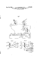
- Fig..1 is a diagrammatic view of a follow-up system according to the invention for controlling the azimuth adjustment of a gun.
- Fig. 2 is a typical circuit diagram of the control means for controlling. the filter network in accordance with the strength of the output signals, and
- Fig. 3' is a modified circuit diagram of the control means of Fig, 2.
- the follow-up system comprises a gun sight 1 ofconventional design.
- Thissight constitutes the control unit of the system and includes, among other components, a control bow mounted for pivoting about a horizontal axis and rotation about a vertical axis, pivoting about the horizontal axis serving to vary the elevational' posi tionof the gun and rotation. about the vertical axis to vary the azimuth or lateral position of the gun.
- a rotation of the control how is transmitted by suitable coupling means diagrammatically shown as a shaft 2, gears 3, 4 and a shaft 5 to a synchronizing device 6.
- This device or selsyn unit is of conventional design and should be visualized as comprising a stator and a rotor each provided with appropriate windings, shaft 5 constituting the rotor shaft so that a rotation of the control bow varies the angular position of the rotor windings relative to the stator windings.
- the controlled unit of thesystem is shown as a gun 14, the platform of which supports a rotary shaft 12' shaft 9 and the gun platform are illustrated in a diagram-' matic manner only.
- the rotor windings of device 6 are connected to an A.-C. source 7 and the stator windings of the two devices are interconnected. However, it would also be possible to feed the A.-C. potential to the rotor winding of device 8.
- the character of the output signals of the devices is determined by the relative position of the rotors of the devices, or in other words by the relative position of control unit 1 and controlled unit 14. It will further be apparent that the two devices function in the nature of an.A.-C. selsyn system and any conventional system of this type can be employed, unit 6 being the pilot unit and unit 8 the follower of the system.
- Shaft 12 is rotated by means of a rotary drive unit 13.
- the design of this. drive unit does not constitute part of the present invention. It sufiices to say that it is reversible and adjustable as to speed.
- the drive unit is symbolized by a block.
- the rotor windings of device 8 are connected to the inputside of A.-C. amplifying means 15 of conventional design the output side of which is connected to conventional phase detecting means 16 which are also connected to the A.-C. source 7 so that'the same A.-C. potential is fed to the detecting means as is fed to the rotor windings of device 6.
- the phase detecting means are followed by a D.-C. amplifying means 17, filter network means 18 and an output stage 19 which may include an electronic valve coupling of conventional design. All the aforementioned means are connected in a cascade circuit.
- the signal generated by a unit 8 and supplied to amplifier 15 is in the nature of a modulated carrier-wave signal.
- the carrier wave has a frequency of about 400 cycles per second and isgenerated by unit 7.
- the modulation signal in the carrier-wave signal is used to control drive unit 13.
- the carrier wave signal is amplified in amplifier 15 and demodulated in detector 16.
- - Detector 16 supplies to amplifier 17 a signal equal to the modulation signal.
- the output stage 19 is connected to ground through a control means 22 and a regulating device 21 shown as a differential relay.
- This relay comprises two coils 20 and 23 of which coil 20'is connected by leads 36 between one terminal of output stage 19, control means 22and ground and coil 23 is connected by leads 37 between the other terminal of output stage 19, control means 22 and ground.
- the differential relay further comprises a movable core bar 25 supporting an armature 26 the position of which relative to coils 20 and 23 is controlled by the flow of current through these coils as will be more fully explained hereinafter.
- the differential relay serves to control the operation of drive unit 13.
- the operative coupling between the relay and the drive unit is diagrammatically shown as an arm 27 pivoted on one end to;
- a pointer 29 movable together with shaft 28 and coacting with a scale 30 serves to indicate the speed and rotational direction of the drive unit.
- the filter network means 18 are shown as comprising 7 series arms including resistance means 31 and32'respecand capacitance means 33 in series connection.
- FIG. 2 shows a circuit diagram of control means 22 and switch means 35 controlled by the control means 22.
- the circuit diagram of this figure-and also of Fig. 3 is kept as simple as possible to illustrate the operation of the control means. In practice, the control means may. be entirely different and much more involved but it is believed that circuits of Figs. 2 and 3 suffice to explain-the invention.
- the switch means 35 are connected in shunt with capacitance means 33 and it is only essential for the invention that the switch means short circuit the capacitance means when the signal strength is above the predetermined value.
- the circuit diagram of Fig. 2 comprises a differential relay similar to the differential relay 21.
- the two coils 38 and 39 of the relay are connected in series with coils are shown as a make and break switch of the type used in the telephone art.
- the movable contact of the switch is shown as a contact spring 41 fastened to armature 40 and connected by a lead 42 to one side of capacitor 33..
- the two contact springs 43 and 44 of the switch are interconnected and connected by a lead 45 to the other side of capacitor 33.
- the differential relay of control means 22 is connected in parallel to coils 20 and 23 of differential relay 21.
- resistance means 46 are connected in circuit withcoils '20 and 23, the midpoint of the resistance means, being grounded.
- Coils 38 and 39 are connected in parallel to each half of resistance means 46.
- the envelope or character of the output signal of the rotorof the device 8 is a function.
- the system is so adjusted, as is well known for the purpose, that the output signal of the rotor of device 8 has a predetermined value when the position of the controlled unit corresponds to the position of the; control unit.
- the system is setfor a zero signal when the positions of the two units are synchronized.
- the phase detector 16 to which is fed the same A.-C. potential as to the rotor of device 6 generates a positive D.-C. signal when the output signal from the rotor of;
- D.-C. signals are then fed to the D.-C. amplifying means 17, the filter network 18 and the output stage i 19.
- Coils 20 and 23 of differential relay 21 are so connected to the D.-C. amplifier 17 that the D.-C. currents flowing through, the coils are equal or zero when the positions of the controlled unit and the control unit are.
- contact spring 41 is in its middle or disengaged position as long as the flow of current through coils 38 and 39 is not sufficient to attract armature 40 into either direction.
- capacitor 33 is included in the filter network.
- contact spring 41 engages either contact spring 43 or contact spring 44 thereby short-circuiting capacitor 33 until armature 49 returns into or near its neutral position.
- the circuit diagram of Fig. 3 operates in basically the same manner so that a further description of this figure does not appear to be essential for the understanding of the invention.
- Fig. 1 shows an exemplification of the invention in connection with the azimuth adjustment of a gun.
- the same problem exists in connection with the elevational adjustment of the gun and that the same follow-up system in combination with control means according to the invention can be employed to avoid delayed positioning of the gun in eleva- U tional direction.
- a follow-up system for positioning a controlled unit by a control unit situated at a remote point comprising electric signal means operatively connected with the control unit and the controlled unit and arranged to generate an error signal variable in strength corresponding to the position of the control unit and the controlled unit relative one to the other, amplifying means including filter network means connected in circuit with the signal means for feeding the said error signal to the input side of the amplifying means, reversible drive means operatively connected with the controlled unit for moving the latter, electric regulating means connected in circuit with the drive means for operational and directional control of the same and with the output side of the amplifying means for control of the regulating means by the signal output of the amplifying means as passed by the filter network means, the said filter network means including components sensitive to the signal strength and impeding the normal operation of the system in response to a signal having a strength above a predetermined value, and electric control means responsive to the signal strength and arranged electrically to inactivate the said components in response to a signal above the said predetermined value.
- a follow-up system for positioning a controlled unit by a control unit situated at a remote point comprising electric signal means operatively connected with the control unit and the controlled unit and arranged to generate an error signal variable in strength corresponding to the position of the control unit and the controlled unit relative one to the other, amplifying means including filter network means connected in circuit with the signal means for feeding the said error signal to the input side of the amplifying means, reversible drive means operatively connected with the controlled unit for moving the latter, electric regulating means connected in circuit with the drive means for operational and directional control of the same and with the output side of the amplify ing means for control of the regulating means by the signal output of the amplifying means, the said filter network means including components sensitive to the signal strength and impeding the normal operation of the system in response to a signal having a strength above a predetermined value, and electromagnetic control means responsive to the signal strength and arranged to short-circuit the said components of the filter network means in response to receiving a signal having a strength above the said
- the said filter network means comprise a shunt arm including capacitance means and resistance means, said capacitance means constituting the said components capable of impeding a normal operation of the network, and wherein the said electromagnetic means comprise switch means connected in shunt with said capacitance means and arranged to short-circuit said capacitance means in response to a signal having a strength above the said predetermined value.
- control switch means comprise switch contacts biased into a disengaged position
- said electromagnetic means include coil means arranged to move said switch contacts into the engaged position for shortcircuiting said capacitance means thereby varying the characteristics of the filter network means and the influence thereof upon the error signal without blocking the passage of the latter.
- a follow-up system for positioning a controlled unit by a control unit situated at a remote point comprising electric signal means operatively connected with the control unit and the controlled unit and arranged to generate an error signal variable in strength as a function of the position of the control unit and the controlled unit relative one to the other, said signal means including selsyn devices operatively connected to the control unit and the controlled unit restively for control thereby, an A.-C. source and phase-detecting means connected in circuit so as to cause the phase-detecting means to generate a positive D.-C. signal when the output signal from the selsyn devices is in phase with the signal from the A.-C. source and a negative D.-C.
- D.-C. amplifying means connected in circuit with said phase-detecting means and including filter network means, reversible drive means operatively connected in circuit with the controlled unit for moving the latter, electric regulating means connected in circuit with the drive means for operational and directional control of the latter corresponding to the sign of said D.-C.
- the said network means including components sensitive to the filter strength and impeding the normal operation of the system in response to a signal of either sign having a strength above a predetermined value, an electric control means responsive to the signal strength connected in circuit with the amplifying means and rendering inactive the said components in response to a signal of either sign above the said predetermined value.
- the said regulating means comprise diiferential relay means including two coil means, one of said coil means being connected for energization by a positive signal and the other for energi zation by a negative D.-C. signal, energization of one of said coil means effecting actuation of the drive means in one direction and energization of the other of said coil means efiecting actuation of the drive means in the opposite direction.
- said electric control means comprise second difierential relay means including two coil means, one of said coil means being connected in circuit with one of the coil means of said first differential relay means and the other in circuit with the second coil means of said first relay means, and switch means for shortcircuiting said components, each of the coil means of the second relay means being arranged to be energized in response to a signal of corresponding sign and above a predetermined strength.
Landscapes
- Physics & Mathematics (AREA)
- General Physics & Mathematics (AREA)
- Engineering & Computer Science (AREA)
- Automation & Control Theory (AREA)
- Control Of Position Or Direction (AREA)
Description
Nov. 20, 1956 Filed June 14, 1952 I; 17 3/ J3 7 f Pl-mss {8 OUTPUT flMPLlF/ER 05754702 AMPLIFIE JrAGE A. H. P. BLOMQVIST ETAL CONTROL FOLLOW-UP SYSTEM FOR POSITIONING REMOTE A CONTROLLED UNIT BY A CONTROL UNIT IN VEN TORS.
HUGO P578115 BLOMQU/ST PER AKE L/NDEGREN BY ML lua ATTORNEY United States Patent O REMOTE CONTROL FOLLOW-UP SYSTEM FOR POSITIONING A CONTROLLED UNIT BY A CONTROL UNIT Ake Hugo Petrus Blomqvist, Johanneshov, and Per Ake Lindegren, Stockholm, Sweden, assignors to Aktie bolaget Bofors, Bofors, Sweden, a Swedish corporation Application June 14, 1952, Serial No. 293,701
Claims priority, application Sweden June 16, 1951 9'Claims. Cl. 318-30) This invention relates to follow-up systems for positioning a controlled unit by operation of a control unit situated at a remote point.
While follow-up systems of this kind have many use.- ful applications, a now preferred field of application of the invention is the elevationa'l and lateral aiming of a gum by remote control.
There are known for this purpose remote control systems, the control unit and controlled unit of which are each connected to a signal generating synchronizing device or selsyn unit. Each :of these synchronizing devices or selsyn units comprises a stator and a rotor so that when an A.-C. voltage is supplied to the stator an output voltage is produced in the rotor winding the character of which depends obviously upon the angular position of the rotor relative to the stator, By connecting the stators of the two devices and applying an alternating voltage to the rotor of one device a signal is obtained from the rotor of the other device. The form or envelope of this signal depends upon the difference between the position of the controlled unit and the control unit, the position of the latter unit determining the final position desired for the controlled unit. The signals obtained from the rotors of the synchronizer devices, which are in effect signal means, are fed through transmission means to drive means operatively coupled with the controlled unit for moving the same into the desired position. These transmission means generally include A.-C. amplifying means, phase detecting means, D.-C. amplifying means, and regulating or control means for control of the drive means.
As will appear from the previous explanations of the conventional remote control devices, the positioning of the controlled unit is effected by a signalthe character or envelope of which is determined by the relative rotor position. An analysis .of these signals shows that it may contain pure sine signals both of high and low frequency. Experience shows that these sine signals, particularly those of high frequency, tend to cause disturbances by causing the system to become self-oscillating. Generally, this is the case when the amplification in the system exceeds a certain value. In other words, to avoid selfoscillation of the system, the amplification should not exceed a certain value which value in turn is of course determined by the lay-out of the specific system. With signals of low frequency disturbances in the nature of self-oscillations do not appear so that the amplification can be selected without regard to the aforementioned safe maximum value.
With remote control systems of the general type, herein referred to, it is desirable to use a relatively high amplification irrespectively Whether or not the signals are of high frequency or of low frequency since a high amplification is necessary or at least advantageous tor a rapid follow-up action of the controlled unit. Obviously, it is desirable to-move the controlled unit, such as a gun, asquickly as possible into its end position.
Patented Nov. 20, 1 956 It has already been proposed to associate the D.-C. amplifying means with a filter network having a shunt arm including resistance means and capacitance means connected in series.
A network of this type, when suitably laid out, serves to limit the amplification to the aforementioned permissible maximum value when high frequency signals.
are generated. However, the difiiculty is that the net- Work operates satisfactorily only when the deviations between a momentary position of a controlled unit such as a firearm, sand the final position as demanded by the control unit, such as a sighting mechanism, arecomparatively small so that the signals received by the controlled unit are comparatively weak.. However, in practice it is not always possible to limit the operation of at which the filter network can operate.
Accordingly, one of the main objects of the present invention is to provide means which assure a prompt and immediate operation of the filter network under all.
conditions, that is independentlyof the degree of deviation between the momentary position and the final position :of the controlled unit.
A more specific object of the invention is to combine control means with a follow-up system of the general type, above referred to, which means are so designed that they render the capacitance means of the filter network automatically inoperative when the strength of the output signals is above a predetermined value.
Other and further objects, features and advantages of the invention will be pointed out hereinafter and set forth in the appended claims forming part of the application.
In the accompanying drawing several now preferred embodiments of the invention are shown by way of illustration and not by way of limitation.
In the drawing:
Fig..1 is a diagrammatic view of a follow-up system according to the invention for controlling the azimuth adjustment of a gun.
Fig. 2 is a typical circuit diagram of the control means for controlling. the filter network in accordance with the strength of the output signals, and
Fig. 3' is a modified circuit diagram of the control means of Fig, 2.
Referring first to Fig. 1 in detail, the follow-up system according to this figure comprises a gun sight 1 ofconventional design. Thissight constitutes the control unit of the system and includes, among other components, a control bow mounted for pivoting about a horizontal axis and rotation about a vertical axis, pivoting about the horizontal axis serving to vary the elevational' posi tionof the gun and rotation. about the vertical axis to vary the azimuth or lateral position of the gun. A rotation of the control how is transmitted by suitable coupling means diagrammatically shown as a shaft 2, gears 3, 4 and a shaft 5 to a synchronizing device 6. This device or selsyn unit is of conventional design and should be visualized as comprising a stator and a rotor each provided with appropriate windings, shaft 5 constituting the rotor shaft so that a rotation of the control bow varies the angular position of the rotor windings relative to the stator windings.
The controlled unit of thesystem is shown as a gun 14, the platform of which supports a rotary shaft 12' shaft 9 and the gun platform are illustrated in a diagram-' matic manner only.
The rotor windings of device 6 are connected to an A.-C. source 7 and the stator windings of the two devices are interconnected. However, it would also be possible to feed the A.-C. potential to the rotor winding of device 8. As will be apparent, the character of the output signals of the devices is determined by the relative position of the rotors of the devices, or in other words by the relative position of control unit 1 and controlled unit 14. It will further be apparent that the two devices function in the nature of an.A.-C. selsyn system and any conventional system of this type can be employed, unit 6 being the pilot unit and unit 8 the follower of the system.
Shaft 12 is rotated by means of a rotary drive unit 13. The design of this. drive unit does not constitute part of the present invention. It sufiices to say that it is reversible and adjustable as to speed. The drive unit is symbolized by a block.
The rotor windings of device 8 are connected to the inputside of A.-C. amplifying means 15 of conventional design the output side of which is connected to conventional phase detecting means 16 which are also connected to the A.-C. source 7 so that'the same A.-C. potential is fed to the detecting means as is fed to the rotor windings of device 6. The phase detecting means are followed by a D.-C. amplifying means 17, filter network means 18 and an output stage 19 which may include an electronic valve coupling of conventional design. All the aforementioned means are connected in a cascade circuit. The signal generated by a unit 8 and supplied to amplifier 15 is in the nature of a modulated carrier-wave signal. The carrier wave has a frequency of about 400 cycles per second and isgenerated by unit 7. The modulation signal in the carrier-wave signal is used to control drive unit 13. The carrier wave signal is amplified in amplifier 15 and demodulated in detector 16.- Detector 16 supplies to amplifier 17 a signal equal to the modulation signal. The output stage 19 is connected to ground through a control means 22 and a regulating device 21 shown as a differential relay. This relay comprises two coils 20 and 23 of which coil 20'is connected by leads 36 between one terminal of output stage 19, control means 22and ground and coil 23 is connected by leads 37 between the other terminal of output stage 19, control means 22 and ground. The differential relay further comprises a movable core bar 25 supporting an armature 26 the position of which relative to coils 20 and 23 is controlled by the flow of current through these coils as will be more fully explained hereinafter. The differential relay serves to control the operation of drive unit 13. The operative coupling between the relay and the drive unitis diagrammatically shown as an arm 27 pivoted on one end to;
The filter network means 18 are shown as comprising 7 series arms including resistance means 31 and32'respecand capacitance means 33 in series connection.
A temporarily inoperative for this purpose when the signal strength is above a certain maximum value.
Referring now to Fig. 2, this figure shows a circuit diagram of control means 22 and switch means 35 controlled by the control means 22. Before describing Fig. 2 more in detail, it should be pointed out that the circuit diagram of this figure-and also of Fig. 3 is kept as simple as possible to illustrate the operation of the control means. In practice, the control means may. be entirely different and much more involved but it is believed that circuits of Figs. 2 and 3 suffice to explain-the invention. As will appear from the figures the switch means 35 are connected in shunt with capacitance means 33 and it is only essential for the invention that the switch means short circuit the capacitance means when the signal strength is above the predetermined value.
The circuit diagram of Fig. 2 comprises a differential relay similar to the differential relay 21. The two coils 38 and 39 of the relay are connected in series with coils are shown as a make and break switch of the type used in the telephone art. The movable contact of the switch is shown as a contact spring 41 fastened to armature 40 and connected by a lead 42 to one side of capacitor 33..
The two contact springs 43 and 44 of the switch are interconnected and connected by a lead 45 to the other side of capacitor 33. According to the circuit diagram of Fig. 3 the differential relay of control means 22 is connected in parallel to coils 20 and 23 of differential relay 21. For thispurpose resistance means 46 are connected in circuit withcoils '20 and 23, the midpoint of the resistance means, being grounded. Coils 38 and 39 are connected in parallel to each half of resistance means 46.
The operation of the follow-up system, as hereinbe-j fore described, is as follows:
As previously stated, the envelope or character of the output signal of the rotorof the device 8 is a function.
of the relative position of the rotors of the two devices or, in other words, a function of the deviation of the position of the controlled unit from the position of the control unit. The system is so adjusted, as is well known for the purpose, that the output signal of the rotor of device 8 has a predetermined value when the position of the controlled unit corresponds to the position of the; control unit. Generally, the system is setfor a zero signal when the positions of the two units are synchronized.
The phase detector 16 to which is fed the same A.-C. potential as to the rotor of device 6 generates a positive D.-C. signal when the output signal from the rotor of;
device 8 is in phase with the signal from the A.-C. source 7, and a negative D.-C. signal is generated by the detector when the signal from the rotor of device 8 is in opposite phase. The D.-C. signals are then fed to the D.-C. amplifying means 17, the filter network 18 and the output stage i 19. Coils 20 and 23 of differential relay 21 are so connected to the D.-C. amplifier 17 that the D.-C. currents flowing through, the coils are equal or zero when the positions of the controlled unit and the control unit are.
equalized, that is, when the gun is in the position demanded by the sight.
, Let it now be assumed that detector 16 generates positive direct current. tively, and a shunt arm including resistance means 34- Then, the flow of current through coil 20 is increased and the flow of current through coil 23 is decreased. As a result, armature 26 is attracted by coil 20 therebyactuating drive unit 13 to operate in 'a direction in which the gun is moved toward a position" in which the output signal of the rotor of device 8 be- The speed with which the drive unit op-= comes ZBI'O.
Furthermore, the strength with;
crates and hence the gun is moved depends upon the strength of the output signal from the rotor of device 8. The stronger this signal is the more the armature 26 will be attracted thereby setting the drive unit for a higher speed.
When the current from the detector 16 is negative, armature 26 is attracted by coil 23 and the gun is moved in the opposite direction again with a speed dependent upon the strength of the signal.
As will be apparent, from an examination of Fig. 2, and the previous description, contact spring 41 is in its middle or disengaged position as long as the flow of current through coils 38 and 39 is not sufficient to attract armature 40 into either direction. As a result, capacitor 33 is included in the filter network. However, as soon as either of the coils 38 and 39 attracts armature 40 contact spring 41 engages either contact spring 43 or contact spring 44 thereby short-circuiting capacitor 33 until armature 49 returns into or near its neutral position. The circuit diagram of Fig. 3 operates in basically the same manner so that a further description of this figure does not appear to be essential for the understanding of the invention.
Fig. 1 shows an exemplification of the invention in connection with the azimuth adjustment of a gun. However, it will be apparent, that the same problem exists in connection with the elevational adjustment of the gun and that the same follow-up system in combination with control means according to the invention can be employed to avoid delayed positioning of the gun in eleva- U tional direction.
While the invention has been described in detail with respect to certain now preferred examples and embodiments of the invention it will be understood by those skilled in the art after understanding the invention, that various changes and modifications may be made without departing from the spirit and scope of the invention, and it is intended, therefore, to cover all such changes and modifications in the appended claims.
What is claimed as new and desired to be secured by Letters Patent is:
We claim:
1. A follow-up system for positioning a controlled unit by a control unit situated at a remote point, the said system comprising electric signal means operatively connected with the control unit and the controlled unit and arranged to generate an error signal variable in strength corresponding to the position of the control unit and the controlled unit relative one to the other, amplifying means including filter network means connected in circuit with the signal means for feeding the said error signal to the input side of the amplifying means, reversible drive means operatively connected with the controlled unit for moving the latter, electric regulating means connected in circuit with the drive means for operational and directional control of the same and with the output side of the amplifying means for control of the regulating means by the signal output of the amplifying means as passed by the filter network means, the said filter network means including components sensitive to the signal strength and impeding the normal operation of the system in response to a signal having a strength above a predetermined value, and electric control means responsive to the signal strength and arranged electrically to inactivate the said components in response to a signal above the said predetermined value.
2. A follow-up system for positioning a controlled unit by a control unit situated at a remote point, the said system comprising electric signal means operatively connected with the control unit and the controlled unit and arranged to generate an error signal variable in strength corresponding to the position of the control unit and the controlled unit relative one to the other, amplifying means including filter network means connected in circuit with the signal means for feeding the said error signal to the input side of the amplifying means, reversible drive means operatively connected with the controlled unit for moving the latter, electric regulating means connected in circuit with the drive means for operational and directional control of the same and with the output side of the amplify ing means for control of the regulating means by the signal output of the amplifying means, the said filter network means including components sensitive to the signal strength and impeding the normal operation of the system in response to a signal having a strength above a predetermined value, and electromagnetic control means responsive to the signal strength and arranged to short-circuit the said components of the filter network means in response to receiving a signal having a strength above the said predetermined value.
3. A follow-up system as defined in claim 1, wherein the electric control means are connected in series with said regulating means.
4. A follow-up system as defined in claim 1, wherein the electric control means are connected in parallel with said regulating means.
5. A follow-up system as defined in claim 2, wherein the said filter network means comprise a shunt arm including capacitance means and resistance means, said capacitance means constituting the said components capable of impeding a normal operation of the network, and wherein the said electromagnetic means comprise switch means connected in shunt with said capacitance means and arranged to short-circuit said capacitance means in response to a signal having a strength above the said predetermined value.
6. A follow-up system according to claim 5, wherein the said control switch means comprise switch contacts biased into a disengaged position, and wherein said electromagnetic means include coil means arranged to move said switch contacts into the engaged position for shortcircuiting said capacitance means thereby varying the characteristics of the filter network means and the influence thereof upon the error signal without blocking the passage of the latter.
7. A follow-up system for positioning a controlled unit by a control unit situated at a remote point, the said system comprising electric signal means operatively connected with the control unit and the controlled unit and arranged to generate an error signal variable in strength as a function of the position of the control unit and the controlled unit relative one to the other, said signal means including selsyn devices operatively connected to the control unit and the controlled unit restively for control thereby, an A.-C. source and phase-detecting means connected in circuit so as to cause the phase-detecting means to generate a positive D.-C. signal when the output signal from the selsyn devices is in phase with the signal from the A.-C. source and a negative D.-C. signal when the said output signal is in opposite phase with the signal from the A.-C. source, D.-C. amplifying means connected in circuit with said phase-detecting means and including filter network means, reversible drive means operatively connected in circuit with the controlled unit for moving the latter, electric regulating means connected in circuit with the drive means for operational and directional control of the latter corresponding to the sign of said D.-C. signal and with the output side of the amplifying means including said filter network means, the said network means including components sensitive to the filter strength and impeding the normal operation of the system in response to a signal of either sign having a strength above a predetermined value, an electric control means responsive to the signal strength connected in circuit with the amplifying means and rendering inactive the said components in response to a signal of either sign above the said predetermined value.
8. A follow-up system according to claim 7, wherein the said regulating means comprise diiferential relay means including two coil means, one of said coil means being connected for energization by a positive signal and the other for energi zation by a negative D.-C. signal, energization of one of said coil means effecting actuation of the drive means in one direction and energization of the other of said coil means efiecting actuation of the drive means in the opposite direction.
9. A follow-up system according to claim 8, wherein the said electric control means comprise second difierential relay means including two coil means, one of said coil means being connected in circuit with one of the coil means of said first differential relay means and the other in circuit with the second coil means of said first relay means, and switch means for shortcircuiting said components, each of the coil means of the second relay means being arranged to be energized in response to a signal of corresponding sign and above a predetermined strength.
References Cited in the file of this patent UNITED STATES PATENTS
Applications Claiming Priority (4)
| Application Number | Priority Date | Filing Date | Title |
|---|---|---|---|
| SE2771573X | 1951-06-16 | ||
| SE1012990X | 1951-06-16 | ||
| SE1062603X | 1951-06-16 | ||
| SE710042X | 1951-06-16 |
Publications (1)
| Publication Number | Publication Date |
|---|---|
| US2771573A true US2771573A (en) | 1956-11-20 |
Family
ID=27484583
Family Applications (1)
| Application Number | Title | Priority Date | Filing Date |
|---|---|---|---|
| US293701A Expired - Lifetime US2771573A (en) | 1951-06-16 | 1952-06-14 | Remote control follow-up system for positioning a controlled unit by a control unit |
Country Status (2)
| Country | Link |
|---|---|
| US (1) | US2771573A (en) |
| NL (1) | NL84792C (en) |
Cited By (2)
| Publication number | Priority date | Publication date | Assignee | Title |
|---|---|---|---|---|
| US2950616A (en) * | 1954-09-13 | 1960-08-30 | Bofors Ab | Apparatus for determining the physical output of a servo-system |
| US3441825A (en) * | 1965-11-29 | 1969-04-29 | Gen Electric | Selected gain control system |
Citations (8)
| Publication number | Priority date | Publication date | Assignee | Title |
|---|---|---|---|---|
| US2421230A (en) * | 1936-05-12 | 1947-05-27 | Arma Corp | Electrohydraulic position control system |
| US2448387A (en) * | 1946-04-23 | 1948-08-31 | Ford Instr Co Inc | Electric motor follow-up system |
| US2528486A (en) * | 1939-07-31 | 1950-11-07 | Vickers Electrical Co Ltd | Electric follow-up control system |
| US2596698A (en) * | 1948-06-10 | 1952-05-13 | Honeywell Regulator Co | Synchronizing arrangement |
| US2668264A (en) * | 1952-04-24 | 1954-02-02 | Leeds & Northrup Co | Measuring system of the balanceable network type |
| US2670456A (en) * | 1950-06-30 | 1954-02-23 | Rca Corp | Switching system for dual-speed electric servo mechanism |
| US2673314A (en) * | 1950-05-03 | 1954-03-23 | Bendix Aviat Corp | Positioning system monitor |
| US2679622A (en) * | 1951-05-19 | 1954-05-25 | Gen Precision Lab Inc | Curve follower |
-
0
- NL NL84792D patent/NL84792C/xx active
-
1952
- 1952-06-14 US US293701A patent/US2771573A/en not_active Expired - Lifetime
Patent Citations (8)
| Publication number | Priority date | Publication date | Assignee | Title |
|---|---|---|---|---|
| US2421230A (en) * | 1936-05-12 | 1947-05-27 | Arma Corp | Electrohydraulic position control system |
| US2528486A (en) * | 1939-07-31 | 1950-11-07 | Vickers Electrical Co Ltd | Electric follow-up control system |
| US2448387A (en) * | 1946-04-23 | 1948-08-31 | Ford Instr Co Inc | Electric motor follow-up system |
| US2596698A (en) * | 1948-06-10 | 1952-05-13 | Honeywell Regulator Co | Synchronizing arrangement |
| US2673314A (en) * | 1950-05-03 | 1954-03-23 | Bendix Aviat Corp | Positioning system monitor |
| US2670456A (en) * | 1950-06-30 | 1954-02-23 | Rca Corp | Switching system for dual-speed electric servo mechanism |
| US2679622A (en) * | 1951-05-19 | 1954-05-25 | Gen Precision Lab Inc | Curve follower |
| US2668264A (en) * | 1952-04-24 | 1954-02-02 | Leeds & Northrup Co | Measuring system of the balanceable network type |
Cited By (2)
| Publication number | Priority date | Publication date | Assignee | Title |
|---|---|---|---|---|
| US2950616A (en) * | 1954-09-13 | 1960-08-30 | Bofors Ab | Apparatus for determining the physical output of a servo-system |
| US3441825A (en) * | 1965-11-29 | 1969-04-29 | Gen Electric | Selected gain control system |
Also Published As
| Publication number | Publication date |
|---|---|
| NL84792C (en) |
Similar Documents
| Publication | Publication Date | Title |
|---|---|---|
| US2654999A (en) | Controlled damping servo mechanism | |
| US2423534A (en) | Control apparatus | |
| US2760131A (en) | Nonlinear gain servo systems | |
| US2561654A (en) | Servo system with fine and coarse adjustment | |
| US2398419A (en) | Radio operated positioning control system | |
| US2771573A (en) | Remote control follow-up system for positioning a controlled unit by a control unit | |
| US2428402A (en) | Noncorrespondence alarm for synchros | |
| US2471637A (en) | Automatic steering control | |
| US2464249A (en) | Electrical follow-up system | |
| US2176102A (en) | Lag compensator for electrical control systems | |
| US2671875A (en) | Quadrature rejection system | |
| US2472167A (en) | Frequency sensitive circuit | |
| US2751535A (en) | Position control system | |
| US2462095A (en) | Rate circuits | |
| US2503046A (en) | Self-tuning filter circuit | |
| US2810874A (en) | Servomotor control system | |
| US2492863A (en) | Modulator circuit | |
| US2407876A (en) | Follow-up control system | |
| US2767361A (en) | Remote control follow-up system for positioning a controlled unit by a control unit | |
| US3639810A (en) | Power system monitoring relay | |
| US2917694A (en) | Stabilized servo system | |
| US2642554A (en) | Automatic steering system | |
| US3051882A (en) | Control transformer synchro remote positioning system | |
| US2544922A (en) | Energizing circuit for servo systems | |
| US2524053A (en) | Direct coupled amplifier for servomotor systems |